US10401633B2 - Optical element arrangements for varying beam parameter product in laser delivery systems - Google Patents
Optical element arrangements for varying beam parameter product in laser delivery systems Download PDFInfo
- Publication number
- US10401633B2 US10401633B2 US15/188,076 US201615188076A US10401633B2 US 10401633 B2 US10401633 B2 US 10401633B2 US 201615188076 A US201615188076 A US 201615188076A US 10401633 B2 US10401633 B2 US 10401633B2
- Authority
- US
- United States
- Prior art keywords
- optical element
- lens
- workpiece
- radiation beam
- focusing
- Prior art date
- Legal status (The legal status is an assumption and is not a legal conclusion. Google has not performed a legal analysis and makes no representation as to the accuracy of the status listed.)
- Active, expires
Links
Images


Classifications
-
- G—PHYSICS
- G02—OPTICS
- G02B—OPTICAL ELEMENTS, SYSTEMS OR APPARATUS
- G02B27/00—Optical systems or apparatus not provided for by any of the groups G02B1/00 - G02B26/00, G02B30/00
- G02B27/09—Beam shaping, e.g. changing the cross-sectional area, not otherwise provided for
- G02B27/0927—Systems for changing the beam intensity distribution, e.g. Gaussian to top-hat
-
- G—PHYSICS
- G02—OPTICS
- G02B—OPTICAL ELEMENTS, SYSTEMS OR APPARATUS
- G02B27/00—Optical systems or apparatus not provided for by any of the groups G02B1/00 - G02B26/00, G02B30/00
- G02B27/10—Beam splitting or combining systems
- G02B27/1086—Beam splitting or combining systems operating by diffraction only
-
- G—PHYSICS
- G02—OPTICS
- G02B—OPTICAL ELEMENTS, SYSTEMS OR APPARATUS
- G02B7/00—Mountings, adjusting means, or light-tight connections, for optical elements
- G02B7/003—Alignment of optical elements
- G02B7/005—Motorised alignment
-
- B—PERFORMING OPERATIONS; TRANSPORTING
- B23—MACHINE TOOLS; METAL-WORKING NOT OTHERWISE PROVIDED FOR
- B23K—SOLDERING OR UNSOLDERING; WELDING; CLADDING OR PLATING BY SOLDERING OR WELDING; CUTTING BY APPLYING HEAT LOCALLY, e.g. FLAME CUTTING; WORKING BY LASER BEAM
- B23K26/00—Working by laser beam, e.g. welding, cutting or boring
- B23K26/02—Positioning or observing the workpiece, e.g. with respect to the point of impact; Aligning, aiming or focusing the laser beam
- B23K26/06—Shaping the laser beam, e.g. by masks or multi-focusing
- B23K26/064—Shaping the laser beam, e.g. by masks or multi-focusing by means of optical elements, e.g. lenses, mirrors or prisms
-
- G—PHYSICS
- G02—OPTICS
- G02B—OPTICAL ELEMENTS, SYSTEMS OR APPARATUS
- G02B19/00—Condensers, e.g. light collectors or similar non-imaging optics
- G02B19/0033—Condensers, e.g. light collectors or similar non-imaging optics characterised by the use
- G02B19/0047—Condensers, e.g. light collectors or similar non-imaging optics characterised by the use for use with a light source
- G02B19/0052—Condensers, e.g. light collectors or similar non-imaging optics characterised by the use for use with a light source the light source comprising a laser diode
- G02B19/0057—Condensers, e.g. light collectors or similar non-imaging optics characterised by the use for use with a light source the light source comprising a laser diode in the form of a laser diode array, e.g. laser diode bar
-
- G—PHYSICS
- G02—OPTICS
- G02B—OPTICAL ELEMENTS, SYSTEMS OR APPARATUS
- G02B27/00—Optical systems or apparatus not provided for by any of the groups G02B1/00 - G02B26/00, G02B30/00
- G02B27/09—Beam shaping, e.g. changing the cross-sectional area, not otherwise provided for
- G02B27/0938—Using specific optical elements
- G02B27/0944—Diffractive optical elements, e.g. gratings, holograms
-
- G—PHYSICS
- G02—OPTICS
- G02B—OPTICAL ELEMENTS, SYSTEMS OR APPARATUS
- G02B27/00—Optical systems or apparatus not provided for by any of the groups G02B1/00 - G02B26/00, G02B30/00
- G02B27/09—Beam shaping, e.g. changing the cross-sectional area, not otherwise provided for
- G02B27/0938—Using specific optical elements
- G02B27/095—Refractive optical elements
- G02B27/0955—Lenses
- G02B27/0961—Lens arrays
-
- G—PHYSICS
- G02—OPTICS
- G02B—OPTICAL ELEMENTS, SYSTEMS OR APPARATUS
- G02B27/00—Optical systems or apparatus not provided for by any of the groups G02B1/00 - G02B26/00, G02B30/00
- G02B27/30—Collimators
Definitions
- the present invention relates to laser systems, specifically laser systems with controllable beam parameter products.
- High-power laser systems are utilized for a host of different applications, such as welding, cutting, drilling, and materials processing.
- Such laser systems typically include a laser emitter, the laser light from which is coupled into an optical fiber (or simply a “fiber”), and an optical system that focuses the laser light from the fiber onto the workpiece to be processed.
- the optical system is typically engineered to produce the highest-quality laser beam, or, equivalently, the beam with the lowest beam parameter product (BPP).
- the BPP is the product of the laser beam's divergence angle (half-angle) and the radius of the beam at its narrowest point (i.e., the beam waist, the minimum spot size).
- the BPP quantifies the quality of the laser beam and how well it can be focused to a small spot, and is typically expressed in units of millimeter-milliradians (mm-mrad). (BPP values disclosed herein are in units of mm-mrad unless otherwise indicated.)
- a Gaussian beam has the lowest possible BPP, given by the wavelength of the laser light divided by pi.
- M 2 The ratio of the BPP of an actual beam to that of an ideal Gaussian beam at the same wavelength is denoted, which is a wavelength-independent measure of beam quality.
- the desired beam spot size, divergence, and beam quality may vary depending on, for example, the type of processing and/or the type of material being processed.
- the output optical system or the optical fiber In order to make such changes to the BPP of the laser system, frequently the output optical system or the optical fiber must be swapped out with other components and/or realigned, a time-consuming and expensive process that may even lead to inadvertent damage of the fragile optical components of the laser system.
- there is a need for alternative techniques for varying the BPP of a laser system that do not involve such adjustments to the laser beam or optical system at the output of the optical fiber.
- Embodiments of the present invention use optical elements capable of laser beam shaping to achieve desired spatial beam profiles that modify beam quality (particularly BPP). More specifically, changing the optical geometry of optical elements by moving or displacing their position transverse or longitudinal to the optical axis of the laser beam may be utilized to produce variable BPP.
- optical elements are located in the beam path with switchable states, producing different beam deflections or diffractions, depending on their position.
- the use of optical elements in accordance with embodiments of the present invention enables variation of BPP regardless the shape, quality, wavelength, bandwidth, and number of beams corresponding to the input laser beam(s).
- the output beam with controllably variable BPP may be utilized to process a workpiece in such applications as welding, cutting, drilling, etc.
- variable BPP is improved laser application performance for different types of processing techniques or different types of materials being processed.
- Several techniques have been investigated for modifying laser BPP.
- Laser beam quality may be improved by mode cleaners which include resonant mode cleaners, non-resonant mode cleaners, and optical fiber.
- mode cleaners which include resonant mode cleaners, non-resonant mode cleaners, and optical fiber.
- Various techniques for varying BPP of laser beams have been described in U.S. patent application Ser. No. 14/632,283, filed on Feb. 26, 2015, the disclosure of which is incorporated in its entirety herein by reference. In comparison with mode cleaner cavities or the use of optical single-mode fibers, non-resonant mode cleaners are relatively easy to align.
- This method may be divided into transverse beam shaping by using spatial filter, refractive optics, and adaptive optics, and longitudinal shaping by using time and frequency domain methods. Differing beam intensity distribution that is induced by optical elements (refractive optics) modifies beam quality and, therefore, BPP.
- translation e.g., motorized translation
- real-time dynamic changes of BPP may be realized.
- Laser beam shaping is the process of redistributing the intensity (irradiance) and phase of the beam.
- the intensity distribution defines the beam profile, such as Gaussian, Bessel, annular, multimode, rectangular, top-hat, elliptical or circular, and different intensity profiles may be critical and necessary for specific laser materials processing techniques.
- apodization and truncation Since this approach is fundamentally energy inefficient, reflective optics, refractive optics, diffractive optics, acousto-optics, and/or liquid crystals are generally employed to shape the laser beam by using field-mapping methods.
- Another approach for beam shaping is beam integration, which involves mixing fractions of the input beam to smooth out the intensity spikes, i.e., beam homogenization by means of integration based on splitting the input beam into beamlets that overlap at the focal plane of a lens.
- the optical element is located in the delivery system that delivers the laser beam to the workpiece and focuses the laser.
- the delivery system may be configured and/or packaged as, for example, a cutting head or a welding head.
- Embodiments of the invention vary the beam quality in order to enable a controllably variable BPP at the work station (and/or at the workpiece disposed thereon).
- the variable BPP module may include one or more optical elements, a motorized translating stage, a collimating lens, and a focusing lens.
- Embodiments of the invention may feature any one or more of multiple types of refractive optics for the optical elements are used to vary BPP.
- Embodiments of the invention vary beam quality by dynamically changing the position of one or more optical elements in the optical path of the laser beam.
- the beam profile is tailored by adjusting the beam pointing position on the optical element.
- the optical elements may have different geometries dependent on a desired beam profile and, therefore, BPP.
- One optical element in accordance with embodiments of the invention has a planar surface and a flat-top (i.e., truncated) cone shaped surface.
- Another optical element in accordance with embodiments of the invention has a planar surface and a flat-top spherical shaped surface.
- Yet another optical element in accordance with embodiments of the invention is a meniscus lens.
- optical elements in accordance with embodiments of the invention include paired positive and negative axicon lenses.
- optical elements include twinned, complementary phase-plate lenses, one of which has a partially convex surface and one of which has a complementarily partially concavely curved surface. The edges of the optical elements may be rounded off in order to suppress diffraction effects.
- beam emitters, emitters, or laser emitters, or lasers include any electromagnetic beam-generating device such as semiconductor elements, which generate an electromagnetic beam, but may or may not be self-resonating. These also include fiber lasers, disk lasers, non-solid state lasers, etc.
- each emitter includes a back reflective surface, at least one optical gain medium, and a front reflective surface. The optical gain medium increases the gain of electromagnetic radiation that is not limited to any particular portion of the electromagnetic spectrum, but that may be visible, infrared, and/or ultraviolet light.
- An emitter may include or consist essentially of multiple beam emitters such as a diode bar configured to emit multiple beams.
- the input beams received in the embodiments herein may be single-wavelength or multi-wavelength beams combined using various techniques known in the art.
- Embodiments of the invention may be utilized with wavelength beam combining (WBC) systems that include a plurality of emitters, such as one or more diode bars, that are combined using a dispersive element to form a multi-wavelength beam.
- WBC wavelength beam combining
- Each emitter in the WBC system individually resonates, and is stabilized through wavelength-specific feedback from a common partially reflecting output coupler that is filtered by the dispersive element along a beam-combining dimension.
- Exemplary WBC systems are detailed in U.S. Pat. No. 6,192,062, filed on Feb. 4, 2000, U.S. Pat. No. 6,208,679, filed on Sep. 8, 1998, U.S. Pat. No. 8,670,180, filed on Aug. 25, 2011, and U.S. Pat. No.
- Multi-wavelength output beams of WBC systems may be utilized as input beams in conjunction with embodiments of the present invention for, e.g., BPP control.
- embodiments of the invention feature a laser delivery system for receiving and altering a spatial power distribution of a radiation beam from a beam source and focusing the radiation with the altered spatial power distribution onto a workpiece.
- the laser system includes or consists essentially of a collimating lens for collimating the radiation beam, a focusing lens for receiving the collimated beam and focusing the beam toward the workpiece, an optical element for receiving the radiation beam and altering the spatial power distribution thereof, a lens manipulation system for changing a position of the optical element within a path of the radiation beam, and a controller for controlling the lens manipulation system to achieve a target altered spatial power distribution on the workpiece.
- the optical element may be disposed between the beam source and the collimating lens (i.e., optically downstream of the beam source and optically upstream of the collimating lens).
- Embodiments of the invention may include one or more of the following in any of a variety of combinations.
- the optical element may include, consist essentially of, or consist of a lens having (i) a first surface having the shape of a truncated cone, and (ii) opposite the first surface, a second surface that is substantially planar.
- the first surface may face the beam source.
- the first surface may face away from the beam source.
- the optical element may include, consist essentially of, or consist of a lens having (i) a first surface having the shape of a truncated sphere, and (ii) opposite the first surface, a second surface that is substantially planar.
- the first surface may face the beam source.
- the first surface may face away from the beam source.
- the optical element may include, consist essentially of, or consist of a meniscus lens.
- the meniscus lens may be a positive meniscus lens.
- the meniscus lens may be a negative meniscus lens.
- the optical element may include, consist essentially of, or consist of fused silica and/or zinc sulfide.
- the lens manipulation system may be configured to position the optical element transversely off-center within the path of the radiation beam.
- the laser delivery system may include a second optical element disposed in the path of the radiation beam.
- the second optical element may be disposed between the focusing lens and the workpiece (i.e., disposed optically downstream of the focusing lens and disposed optically upstream of the workpiece).
- the lens manipulation system may be configured to change a position of the second optical element within the path of the radiation beam.
- the second optical element may include, consist essentially of, or consist of a lens having (i) a first surface having the shape of a truncated cone, and (ii) opposite the first surface, a second surface that is substantially planar.
- the first surface may face the beam source.
- the first surface may face away from the beam source.
- the second optical element may include, consist essentially of, or consist of a lens having (i) a first surface having the shape of a truncated sphere, and (ii) opposite the first surface, a second surface that is substantially planar.
- the first surface may face the beam source.
- the first surface may face away from the beam source.
- the second optical element may include, consist essentially of, or consist of a meniscus lens.
- the meniscus lens may be a positive meniscus lens.
- the meniscus lens may be a negative meniscus lens.
- the second optical element may include, consist essentially of, or consist of fused silica and/or zinc sulfide.
- the beam source may include or consist essentially of a beam emitter emitting a plurality of discrete beams, focusing optics for focusing the plurality of beams onto a dispersive element, a dispersive element for receiving and dispersing the received focused beams, and a partially reflective output coupler positioned to receive the dispersed beams, transmit a portion of the dispersed beams therethrough as the radiation beam, and reflect a second portion of the dispersed beams back toward the dispersive element.
- the radiation beam may be composed of multiple wavelengths of radiation.
- the focusing optics may include or consist essentially of one or more cylindrical lenses, one or more spherical lenses, one or more spherical mirrors, and/or one or more cylindrical mirrors.
- the dispersive element may include or consist essentially of a diffraction grating (e.g., a transmissive diffraction grating or a reflective diffraction grating).
- embodiments of the invention feature a laser delivery system for receiving and altering a spatial power distribution of a radiation beam from a beam source and focusing the radiation with the altered spatial power distribution onto a workpiece.
- the laser delivery system includes or consists essentially of a collimating lens for collimating the radiation beam, a focusing lens for receiving the collimated beam and focusing the beam toward the workpiece, first and second optical elements for receiving the radiation beam and altering the spatial power distribution thereof, a lens manipulation system for changing (i) a position of the first optical element within a path of the radiation beam, (ii) a position of the second optical element within the path of the radiation beam, and/or (iii) a distance between the first and second optical elements, and a controller for controlling the lens manipulation system to achieve a target altered spatial power distribution on the workpiece.
- the first and/or second optical element may be disposed between the beam source and the collimating lens (i.e., disposed optically downstream of the beam source and optically upstream of the collim
- Embodiments of the invention may include one or more of the following in any of a variety of combinations.
- the first optical element may include, consist essentially of, or consist of a double-concave axicon lens.
- the second optical element may include, consist essentially of, or consist of a double-convex axicon lens.
- the first optical element may be disposed optically upstream of the second optical element.
- the first optical element may be disposed optically downstream of the second optical element.
- the lens manipulation system may be configured to change the distance between the first and second optical elements within the range of approximately 0 mm to approximately 50 mm, within the range of approximately 0 mm to approximately 20 mm, within the range of approximately 2 mm to approximately 50 mm, or with the range of approximately 2 mm to approximately 20 mm.
- the first optical element may include, consist essentially of, or consist of a lens having (i) a first surface that is substantially planar, and (ii) opposite the first surface, a second surface having (a) a first portion that is convexly curved and (b) a second portion that is substantially planar.
- the second optical element may include, consist essentially of, or consist of a lens having (i) a first surface that is substantially planar, and (ii) opposite the first surface, a second surface having (a) a first portion that is concavely curved and (b) a second portion that is substantially planar.
- the first optical element may be disposed optically upstream of the second optical element.
- the first optical element may be disposed optically downstream of the second optical element.
- the second surface of the first optical element may face the second surface of the second optical element.
- the first surface of the first optical element may face the first surface of the second optical element.
- the first surface of the first optical element may face the second surface of the second optical element.
- the second surface of the first optical element may face the first surface of the first optical element.
- the lens manipulation system may be configured to position the first optical element and/or the second optical element transversely off-center within the path of the radiation beam.
- the first optical element may include, consist essentially of, or consist of fused silica and/or zinc sulfide.
- the second optical element may include, consist essentially of, or consist of fused silica and/or zinc sulfide.
- the beam source may include or consist essentially of a beam emitter emitting a plurality of discrete beams, focusing optics for focusing the plurality of beams onto a dispersive element, a dispersive element for receiving and dispersing the received focused beams, and a partially reflective output coupler positioned to receive the dispersed beams, transmit a portion of the dispersed beams therethrough as the radiation beam, and reflect a second portion of the dispersed beams back toward the dispersive element.
- the radiation beam may be composed of multiple wavelengths of radiation.
- the focusing optics may include or consist essentially of one or more cylindrical lenses, one or more spherical lenses, one or more spherical mirrors, and/or one or more cylindrical mirrors.
- the dispersive element may include or consist essentially of a diffraction grating (e.g., a transmissive diffraction grating or a reflective diffraction grating).
- embodiments of the invention feature a laser delivery system for receiving and altering a spatial power distribution of a radiation beam from a beam source and focusing the radiation with the altered spatial power distribution onto a workpiece.
- the laser delivery system includes or consists essentially of one or more divergence-increasing optical elements for increasing a divergence of the radiation beam, a focusing lens for receiving the radiation beam and focusing the beam toward the workpiece, at least one optical element for receiving the radiation beam and altering the spatial power distribution thereof, a lens manipulation system for changing a position of the at least one optical element within a path of the radiation beam, and a controller for controlling the lens manipulation system to achieve a target altered spatial power distribution on the workpiece.
- Embodiments of the invention may include one or more of the following in any of a variety of combinations.
- the focusing lens may be disposed optically downstream of the one or more divergence-increasing optical elements.
- the at least one optical element may be disposed optically upstream of the focusing lens.
- the one or more divergence-increasing optical elements may include, consist essentially of, or consist of a triple collimator.
- the triple collimator may include, consist essentially of, or consist of (i) a first plano-concave lens, (ii) a second meniscus lens, and (iii) a third plano-convex lens.
- the first plano-concave lens may be disposed optically upstream of the second meniscus lens.
- the second meniscus lens may be disposed optically upstream of the third plano-convex lens.
- the at least one optical element may be disposed optically downstream of the first plano-concave lens.
- the at least one optical element may be disposed optically upstream of the second meniscus lens and/or the third plano-convex lens.
- the at least one optical element may include, consist essentially of, or consist of a lens having (i) a first surface having the shape of a truncated cone, and (ii) opposite the first surface, a second surface that is substantially planar.
- the at least one optical element may include, consist essentially of, or consist of a lens having (i) a first surface having the shape of a truncated sphere, and (ii) opposite the first surface, a second surface that is substantially planar.
- the at least one optical element may include, consist essentially of, or consist of a meniscus lens (e.g., a positive meniscus lens or a negative meniscus lens).
- the lens manipulation system may be configured to position at least one said optical element transversely off-center within the path of the radiation beam.
- the at least one optical element may include, consist essentially of, or consist of a first optical element and a second optical element.
- the first optical element and the second optical element may be separated by a gap therebetween.
- the lens manipulation system may be configured to change (i) a position of the first optical element within a path of the radiation beam, (ii) a position of the second optical element within the path of the radiation beam, and/or (iii) a distance between the first and second optical elements.
- the first optical element may include, consist essentially of, or consist of a double-concave axicon lens.
- the second optical element may include, consist essentially of, or consist of a double-convex axicon lens.
- the first optical element may be disposed optically upstream of the second optical element.
- the first optical element may be disposed optically downstream of the second optical element.
- the lens manipulation system may be configured to change the distance between the first and second optical elements within the range of approximately 0 mm to approximately 50 mm, within the range of approximately 0 mm to approximately 20 mm, within the range of approximately 2 mm to approximately 50 mm, or with the range of approximately 2 mm to approximately 20 mm.
- the first optical element may include, consist essentially of, or consist of a lens having (i) a first surface that is substantially planar, and (ii) opposite the first surface, a second surface having (a) a first portion that is convexly curved and (b) a second portion that is substantially planar.
- the second optical element may include, consist essentially of, or consist of a lens having (i) a first surface that is substantially planar, and (ii) opposite the first surface, a second surface having (a) a first portion that is concavely curved and (b) a second portion that is substantially planar.
- the first optical element may be disposed optically upstream of the second optical element.
- the first optical element may be disposed optically downstream of the second optical element.
- the second surface of the first optical element may face the second surface of the second optical element.
- the first surface of the first optical element may face the first surface of the second optical element.
- the first surface of the first optical element may face the second surface of the second optical element.
- the second surface of the first optical element may face the first surface of the first optical element.
- the lens manipulation system may be configured to position the first optical element and/or the second optical element transversely off-center within the path of the radiation beam.
- the first optical element may include, consist essentially of, or consist of fused silica and/or zinc sulfide.
- the second optical element may include, consist essentially of, or consist of fused silica and/or zinc sulfide.
- the beam source may include or consist essentially of a beam emitter emitting a plurality of discrete beams, focusing optics for focusing the plurality of beams onto a dispersive element, a dispersive element for receiving and dispersing the received focused beams, and a partially reflective output coupler positioned to receive the dispersed beams, transmit a portion of the dispersed beams therethrough as the radiation beam, and reflect a second portion of the dispersed beams back toward the dispersive element.
- the radiation beam may be composed of multiple wavelengths of radiation.
- the focusing optics may include or consist essentially of one or more cylindrical lenses, one or more spherical lenses, one or more spherical mirrors, and/or one or more cylindrical mirrors.
- the dispersive element may include or consist essentially of a diffraction grating (e.g., a transmissive diffraction grating or a reflective diffraction grating).
- optical distance between two components is the distance between two components that is actually traveled by light beams; the optical distance may be, but is not necessarily, equal to the physical distance between two components due to, e.g., reflections from mirrors or other changes in propagation direction experienced by the light traveling from one of the components to the other.
- FIG. 1 is a schematic diagram of a laser beam delivery system in accordance with various embodiments of the invention.
- FIG. 2 is a schematic diagram of a flat-top cone optical element in accordance with various embodiments of the invention.
- FIG. 3A is a graph of BPP variation as a function of the distance of a fused silica flat-top cone optical element from a beam source in accordance with various embodiments of the invention
- FIG. 3B is a graph of BPP variation as a function of the distance of a zinc sulfide flat-top cone optical element from a beam source in accordance with various embodiments of the invention.
- FIG. 4A is a schematic diagram of a laser delivery system having an off-center optical element in accordance with various embodiments of the invention.
- FIGS. 4B-4D depict beam profiles as a function of off-center distance produced by the laser delivery system of FIG. 4A ;
- FIG. 4E is a graph of irradiance as a function of position for the two-peak beam profile depicted in FIG. 4D ;
- FIG. 5 is a schematic diagram of a flat-top spherical optical element in accordance with various embodiments of the invention.
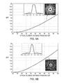
- FIG. 6A is a graph of BPP variation as a function of the distance of a fused silica flat-top spherical optical element from a beam source in accordance with various embodiments of the invention.
- FIG. 6B is a graph of BPP variation as a function of the distance of a zinc sulfide flat-top spherical optical element from a beam source in accordance with various embodiments of the invention.
- FIGS. 7A-7C depict beam profiles as a function of off-center distance produced by a laser delivery system incorporating the optical element of FIG. 5 in accordance with various embodiments of the invention
- FIG. 7D is a graph of irradiance as a function of position for the two-peak beam profile depicted in FIG. 7C ;
- FIG. 8A is a schematic diagram of a portion of a laser delivery system having two axicon-lens optical elements in accordance with various embodiments of the invention.
- FIGS. 8B and 8C depict geometric design parameters of axicon lenses in accordance with various embodiments of the invention.
- FIG. 9 is a graph of the BPP variation as a function of gap distance between positive and negative axicon lenses in accordance with various embodiments of the invention.
- FIG. 10 depicts beam profiles at different gap distances between positive and negative axicon lenses in accordance with various embodiments of the invention.
- FIG. 11 depicts beam profiles at different gap distances between positive and negative axicon lenses that are transversely off-centered in the beam path in accordance with various embodiments of the invention
- FIG. 12A is a schematic diagram of a portion of a laser delivery system having twin phase plate lenses in accordance with various embodiments of the invention.
- FIGS. 12B and 12C depict geometric design parameters of phase plate lenses in accordance with various embodiments of the invention.
- FIG. 12D is a graph of BPP as a function of the inner diameter of twin phase plates in accordance with various embodiments of the invention.
- FIG. 12E is a graph of optimized inner diameter of twin phase plates as a function of separation from an input fiber end cap in accordance with various embodiments of the invention.
- FIG. 12F is a graph of the BPP variation as a function of gap distance between twin phase plate lenses in accordance with various embodiments of the invention.
- FIG. 12G depicts beam profiles at different gap distances between twin phase plate lenses in accordance with various embodiments of the invention.
- FIG. 13A is a schematic diagram of a meniscus lens optical element in accordance with various embodiments of the invention.
- FIG. 13B is a graph of BPP variation as a function of the distance of a fused silica meniscus lens optical element from a beam source in accordance with various embodiments of the invention.
- FIG. 14A is a schematic diagram of a partial laser beam delivery system incorporating a triplet collimator for increased beam divergence in accordance with various embodiments of the invention.
- FIG. 14B is a graph of BPP variation as a function of the distance of a flat-top spherical optical element from a beam source in the laser delivery system of FIG. 14A in accordance with various embodiments of the invention
- FIG. 14C is a graph of BPP variation as a function of the distance of a meniscus lens optical element from a beam source in the laser delivery system of FIG. 14A in accordance with various embodiments of the invention.
- FIG. 14D is a schematic diagram of a partial laser beam delivery system incorporating a triplet collimator for increased beam divergence and twin phase plate optical elements in accordance with various embodiments of the invention.
- FIG. 14E is a graph of the BPP variation as a function of gap distance between the twin phase plate lenses in the laser beam delivery system of FIG. 14D in accordance with various embodiments of the invention.
- FIG. 15 is a schematic diagram of a wavelength beam combining laser system that may be utilized to supply the input beam for laser beam delivery systems in accordance with various embodiments of the invention.
- FIG. 1 depicts a schematic diagram of a laser beam delivery system 100 incorporating beam-manipulating optical elements in accordance with embodiments of the present invention.
- the laser beam delivery system 100 may be disposed within, for example, a laser-based cutting head or welding head.
- the beam delivery system 100 features a beam delivery fiber, terminating in a fiber end cap 105 , that is connected to remaining portions of the laser-generating system (for example, a WBC laser system, not shown in FIG. 1 ), a collimating lens 110 , a focusing lens 115 , and an optical element 120 that is positioned between the end cap 105 and the collimating lens 110 .
- the optical element 120 is disposed close to the fiber end cap 105 to minimize the size of the beam striking the optical element 120 . Refraction of a smaller beam may be performed with optics having smaller geometric dimensions of the optics and may vary the output profile with more sensitivity.
- FIG. 1 also depicts an optional second optical element 125 disposed between the focusing lens 115 and a workpiece 130 .
- the workpiece 130 may include or consist essentially of, for example, one or more parts (e.g., metallic parts) to be welded, drilled, and/or cut by the beam focused by focusing lens 115 .
- the first optical element 120 is disposed between the focusing lens 115 and the workpiece 130 and the second optical element 125 is omitted.
- Optical elements 120 , 125 may each include or consist essentially of, for example, a phase plate.
- first optical element 120 and/or second optical element 125 may be translated within the beam profile via use of a lens manipulation system that may include or consist essentially of, for example, one or more mechanized or motorized translation stages 135 capable of motion along two or three axes.
- the lens manipulation system may be responsive to a controller 140 .
- the controller 140 may be responsive to a desired target radiation power distribution and/or BPP or other measure of beam quality (e.g., input by a user and/or based on one or more properties of a workpiece to be processed such as the distance to the workpiece, the composition of the workpiece, topography of the workpiece, etc.) and configured to position optical element 120 and/or optical element 125 to cause the manipulated beam 145 to strike the workpiece 130 with the target radiation power distribution or beam quality.
- the controller 140 may be programmed to achieve the desired power distribution and/or output BPP and/or beam quality via a particular optical element positioning as detailed herein.
- the controller 140 may be provided as either software, hardware, or some combination thereof.
- the system may be implemented on one or more conventional server-class computers, such as a PC having a CPU board containing one or more processors such as the Pentium or Celeron family of processors manufactured by Intel Corporation of Santa Clara, Calif., the 680x0 and POWER PC family of processors manufactured by Motorola Corporation of Schaumburg, Ill., and/or the ATHLON line of processors manufactured by Advanced Micro Devices, Inc., of Sunnyvale, Calif.
- the processor may also include a main memory unit for storing programs and/or data relating to the methods described herein.
- the memory may include random access memory (RAM), read only memory (ROM), and/or FLASH memory residing on commonly available hardware such as one or more application specific integrated circuits (ASIC), field programmable gate arrays (FPGA), electrically erasable programmable read-only memories (EEPROM), programmable read-only memories (PROM), programmable logic devices (PLD), or read-only memory devices (ROM).
- ASIC application specific integrated circuits
- FPGA field programmable gate arrays
- EEPROM electrically erasable programmable read-only memories
- PROM programmable read-only memories
- PLD programmable logic devices
- ROM read-only memory devices
- the programs may be provided using external RAM and/or ROM such as optical disks, magnetic disks, as well as other commonly used storage devices.
- the programs may be written in any of a number of high level languages such as FORTRAN, PASCAL, JAVA, C, C++, C#, BASIC, various scripting languages, and/or HTML.
- the software may be implemented in an assembly language directed to the microprocessor resident on a target computer; for example, the software may be implemented in Intel 80 ⁇ 86 assembly language if it is configured to run on an IBM PC or PC clone.
- the software may be embodied on an article of manufacture including, but not limited to, a floppy disk, a jump drive, a hard disk, an optical disk, a magnetic tape, a PROM, an EPROM, EEPROM, field-programmable gate array, or CD-ROM.
- FIG. 2 is a schematic diagram of an optical element 200 having the shape of a truncated cone (flat-top cone shape or tapered cylinder shape) in accordance with embodiments of the invention.
- optical element 200 may be utilized as optical element 120 and/or optical element 125 in delivery system 100 .
- the parameters D, d, ⁇ , and H are geometrical design parameters for outside diameter, inside diameter (which may correspond to the beam size of the beam when it strikes the optical element), slope angle which defines the maximum sagitta (or “sag,” h) and the separation of outer ring of the beam from the spot center of the beam, and the thickness of the optical element 200 , respectively.
- Ray tracing of geometric optics may be used to design optical elements in accordance with embodiments of the present invention based on the conservation of energy, the constancy of optical path length and Snell's law.
- the lens design and its surface profiles may, for example, transform the beam profile from a Gaussian into a Bessel laser beam with a desired intensity distribution.
- Table 1 provides exemplary design values for exemplary optical elements 200 including, consisting essentially of, or consisting of two different materials, fused silica and zinc sulfide (e.g., ZnS MultiSpectral, available from II-VI Inc. of Saxonburg, Pa.).
- exemplary optical elements 200 including, consisting essentially of, or consisting of two different materials, fused silica and zinc sulfide (e.g., ZnS MultiSpectral, available from II-VI Inc. of Saxonburg, Pa.).
- FIGS. 3A and 3B are graphs of BPP at different distances from the fiber end cap 105 to the exemplary fused silica ( FIG. 3A ) and zinc sulfide ( FIG. 3B ) optical elements 200 having the design parameters provided in Table 1.
- the initial position of the optical element 200 is assumed to be 25 mm from the end cap 105 .
- the BPP of the beam may be increased from about 4 to about 12 via displacement of the optical element 200 by approximately 30 mm.
- the slope of this change in BPP as a function of displacement may be altered via changes in the numerical aperture of the fiber output at the end cap 105 .
- the beam profiles at a 50 mm distance of the optical element 200 to the fiber end cap 105 are also shown in FIGS. 3A and 3B .
- a tailored beam profile that has two peaks in one axis may be obtained by positioning the optical element 200 (or other optical elements detailed herein) transversely off-center in the beam path (i.e., partially introducing it into the input laser beam) as shown in FIG. 4A .
- the beam profile of the output laser beam may be optimally adapted to a variety of laser applications.
- FIGS. 4B-4D the beam profiles at different off-centered distances (0 mm, 2 mm, and 4 mm) for optical element 200 at a 40 mm distance to the end cap 105 are shown.
- FIG. 4E is a graph of irradiance as a function of position for the beam profile depicted in FIG. 4D , clearly showing the two-peak nature of the beam profile.
- the variation of BPP at different off-centered positions of the optical element 200 is approximately zero, even while the irradiance as a function of position across the beam profile changes.
- Optical elements in accordance with embodiments of the invention may also have a truncated spherical (i.e., flat-top spherical) configuration and may be used to also produce a Bessel beam profile.
- the geometric design for optical elements 500 in accordance with such embodiments is depicted schematically in FIG. 5 .
- Optical element 500 may be utilized as optical element 120 and/or optical element 125 in delivery system 100 .
- the design parameters are the same as those detailed above for the flat-top cone optical element 200 except for the curvature radius R, which also defines the maximum sag (h) and the separation of the resulting annular beam ring from the beam spot center.
- Table 2 provides exemplary design values for exemplary optical elements 500 including, consisting essentially of, or consisting of two different materials, fused silica and zinc sulfide.
- FIGS. 6A and 6B are graphs of BPP at different distances from the fiber end cap 105 to the exemplary fused silica ( FIG. 6A ) and zinc sulfide ( FIG. 6B ) optical elements 500 having the design parameters provided in Table 2.
- the initial position of the optical element 500 is assumed to be 25 mm from the end cap 105 .
- the BPP of the beam may be increased from about 4 to about 12 via displacement of the optical element 500 by approximately 30 mm (e.g., approximately 28 mm-approximately 32 mm).
- the slope of this change in BPP as a function of displacement may be altered via changes in the numerical aperture of the fiber output at the end cap 105 .
- the beam profiles at a 50 mm distance of the optical elements 500 to the fiber end cap 105 are also shown in FIGS. 6A and 6B , as are graphs of their irradiance as a function of position for the 50 mm spacing between optical element 500 and end cap 105 .
- FIGS. 7A-7C the beam profiles at different off-centered distances (0 mm, 2 mm, and 4 mm) for optical element 500 (i.e., as shown for optical element 200 in FIG. 4A ) at a 40 mm distance to the end cap 105 are shown.
- FIG. 7D is a graph of irradiance as a function of position for the beam profile depicted in FIG. 7C , clearly showing the two-peak nature of the intensity of the beam profile.
- the variation of BPP at different off-centered positions of the optical element 500 is approximately zero, even while the irradiance as a function of position across the beam profile changes.
- Embodiments of the invention utilize optical elements to produce annular beam shapes.
- Embodiments of the invention feature one or more optical elements that include, consist essentially of, or consist of axicon lenses.
- axicon lenses are lenses having at least one conical surface, and such lenses may be utilized to image a point source into a line segment along the optical axis.
- the conical surface of revolution is capable of blending light from a point source, which is located on the axis of revolution, by reflection or refraction, or both.
- Embodiments of the invention utilize a combination of a double-positive (i.e., double convex) axicon lens 800 and a double-negative (i.e., double concave) axicon lens 810 between the fiber end cap 105 and the collimating lens 110 as shown in FIG. 8A , and the beam size at the workpiece may be varied utilizing this lensing system.
- lenses 800 , 810 are separated in the beam path by a gap distance 820 .
- ⁇ 1 and ⁇ 2 are the slope variables of the conic surfaces that define the maximum sags (h 1 and h 2 ) and the separation of the annular beam ring from the beam spot center as schematically drawn in FIGS. 8B and 8C .
- the conical surfaces of one or both of lenses 800 , 810 have smooth edges and radii of curvature less than approximately 5 ⁇ m.
- FIG. 9 is a graph depicting control over the BPP of the laser delivery system as a function of the gap distance 820 between the two axicon lenses 800 , 810 .
- an approximate 7 mm variation in the gap distance 820 results in a BPP increase from 4 to 12 , demonstrating the wide range of BPP control enabled by such embodiments of the present invention.
- the beam profiles as a function of gap distance 820 between the lenses 800 , 810 are shown in FIG. 10 , where the gap distances are listed in millimeters.
- adjustment of the gap distance 820 may transform a beam profile having a single peak to one having two, three, or more peaks.
- FIG. 11 depicts similar beam profiles for the case in which the two axicon lenses 800 , 810 are transversely off-center by 4 mm in the beam path and separated by the listed gap distances 820 (gap distances are listed in millimeters).
- Embodiments of the invention feature one or more optical elements that include, consist essentially of, or consist of phase plates having one planar surface and an opposing surface at least a portion of which is convexly or concavely curved.
- FIG. 12A depicts a partial beam delivery system featuring two such plates 1200 , 1210 separated by a gap Z. As shown, plate 1200 is separated from fiber end cap 105 by a distance S.
- the thicknesses of the plates at their outer perimeters are represented by H, and the radii of curvature of the convex/concave portions are represented by R.
- H The thicknesses of the plates at their outer perimeters
- R the radii of curvature of the convex/concave portions.
- the plates 1200 , 1210 have approximately the same H, D, d, and R, although various embodiments of the invention feature twin plates (i.e., one having a partial concave surface and one having a partial convex surface) that differ in one or more of those parameters.
- Table 3 provides exemplary design values for exemplary optical elements 1200 , 1210 including, consisting essentially of, or consisting of two different materials, fused silica and zinc sulfide.
- FIGS. 12D and 12E depict that, in accordance with embodiments of the invention, the inner diameter d of plates 1200 , 1210 may be optimized to maximize the output BPP of the laser delivery system as a function of the distance S from the fiber end cap 105 .
- FIG. 12D is a graph of BPP as a function of inner diameter d for plates 1200 , 1210 having a distance S of 40 mm, a gap distance Z of 10 mm, and a radius of curvature R of 500. As shown, the resulting BPP is maximized at an inner diameter d of approximately 5 mm; this BPP is substantially independent of changes in the gap distance Z and the radius of curvature R.
- FIG. 12D is a graph of BPP as a function of inner diameter d for plates 1200 , 1210 having a distance S of 40 mm, a gap distance Z of 10 mm, and a radius of curvature R of 500.
- the resulting BPP is maximized at an inner diameter d of approximately 5
- 12E is a graph of the optimized inner diameter d (i.e., the inner diameter d that maximizes the output BPP) as a function of the distance S between the end cap 105 and the plate 1200 .
- an optimized inner diameter d may be selected that maximizes BPP of the output beam as a function of the distance S.
- FIG. 12F is a graph of BPP at different gap distances Z between plates 1200 , 1210 having the design parameters provided in Table 3 (with the design parameters of Table 3, both the fused silica and zinc sulfide plates 1200 , 1210 provide the same results).
- the distance S to the end cap 105 is assumed to be 40 mm.
- the BPP of the beam may be increased from about 4 to about 12 via alteration of the gap Z between plates 1200 , 1210 by approximately 9 mm.
- FIG. 12G Various beam profiles of the output beam as a function of the gap Z (in mm) are illustrated in FIG. 12G , as are graphs of their irradiance as a function of position. As shown, as the beam BPP increases, the beam shape proceeds from having a single peak to having a broader, multi-peak irradiance profile.
- Optical elements in accordance with embodiments of the invention may also include, consist essentially of, or consist of meniscus lenses.
- the geometric design for optical elements 1300 in accordance with such embodiments is depicted schematically in FIG. 13A ; as shown, in various embodiments, one surface of optical element 1300 is convexly curved over substantially the entire surface, while the opposing surface is concavely curved over a portion of the surface, defining an inner diameter d.
- Optical element 1300 may be utilized as optical element 120 and/or optical element 125 in delivery system 100 .
- optical element 1300 may have an outer diameter D, inner diameter d, thickness H, maximum sag h 1 of the convexly curved surface, and maximum sag h 2 of the partially concavely curved surface.
- the radius of curvature R which may be approximately the same for both surfaces of optical element 1300 , defines the maximum sags h 1 and h 2 , as well as the separation of the resulting annular beam ring from the beam spot center.
- Table 4 provides exemplary design values for exemplary optical elements 1300 including, consisting essentially of, or consisting of two different materials, fused silica and zinc sulfide.
- FIG. 13B is a graph of BPP at different distances from the fiber end cap 105 to the exemplary fused silica optical element 1300 having the design parameters provided in Table 4.
- the initial position of the optical element 1300 is assumed to be 25 mm from the end cap 105 .
- the BPP of the beam may be increased from about 4 to about 12 via displacement of the optical element 1300 by approximately 24 mm.
- the beam profile at a 46 mm distance of the optical element 1300 to the fiber end cap 105 is also shown in FIG. 13B , as is a graph of the irradiance as a function of position for the 46 mm spacing between optical element 1300 and end cap 105 .
- FIG. 14A depicts portions of a laser delivery system 1400 that incorporates a movable optical element 1405 for BPP variation and a triplet collimator for increasing divergence of the laser beam.
- the triplet collimator increases the divergence of the beam from an angle ⁇ to an angle ⁇ .
- the ratio of ⁇ to ⁇ is between approximately 2 and approximately 1.5, e.g., approximately 1.74. As described in more detail below, this increased divergence enables greater control over BPP with less movement of the optical element 1405 .
- the optical element 1405 includes, consists essentially of, or consists of any one or more of optical element 200 , optical element 500 , optical element 1300 , phase plates 1200 / 1210 , or axicon lenses 800 , 810 .
- FIG. 14A depicts one such embodiment that includes a plano-concave lens 1410 , a meniscus lens 1415 (e.g., a positive meniscus lens), and a plano-convex lens 1420 .
- the optical element 1405 is disposed in the beam path between plano-concave lens 1410 and meniscus lens 1415 .
- the optical element 1405 may be disposed in the beam path between meniscus lens 1415 and plano-convex lens 1420 or even optically downstream of plano-convex lens 1420 .
- FIG. 14B is a graph of BPP at different distances from the fiber end cap 105 to the exemplary fused silica optical element 200 having the design parameters provided in Table 1 when utilized in laser beam delivery system 1400 in conjunction with a triplet collimator for increased beam divergence.
- the initial position of the optical element 200 is assumed to be 25 mm from the end cap 105 .
- the BPP of the beam may be increased from about 4 to about 12 via displacement of the optical element 200 by only approximately 16 mm, or about a factor of 2 less displacement (i.e., greater control) when compared to the beam delivery system lacking the triplet collimator of FIG. 14A (see FIG. 3A ).
- the beam profile at a 21 mm distance of the optical element 200 to the fiber end cap 105 is also shown in FIG. 14B .
- FIG. 14C is a graph of BPP at different distances from the fiber end cap 105 to the exemplary fused silica optical element 1300 having the design parameters provided in Table 4 when utilized in laser beam delivery system 1400 in conjunction with a triplet collimator for increased beam divergence.
- the initial position of the optical element 1300 is assumed to be 25 mm from the end cap 105 .
- the BPP of the beam may be increased from about 4 to about 12 via displacement of the optical element 200 by only approximately 12 mm, or about a factor of 2 less displacement (i.e., greater control) when compared to the beam delivery system lacking the triplet collimator of FIG. 14A (see FIG. 13B ).
- the beam profile at a 17.5 mm distance of the optical element 1300 to the fiber end cap 105 is also shown in FIG. 14C .
- FIG. 14D is a schematic of partial laser beam delivery system 1400 incorporating the twin phase plate optical elements 1200 , 1210 described above separated within the beam path by a gap distance Z.
- FIG. 14E is a graph of BPP for different gap spacings Z of the exemplary fused silica optical elements 1200 , 1210 having the design parameters provided in Table 3 when utilized in laser beam delivery system 1400 in conjunction with a triplet collimator for increased beam divergence. In the plot, the position of the optical element 1200 is assumed to be 25 mm from the end cap 105 .
- the BPP of the beam may be increased from about 4 to about 12 via increasing the gap distance Z between the optical elements 1200 , 1210 by only approximately 3 mm, or about a factor of 3 less displacement (i.e., greater control) when compared to the beam delivery system lacking the triplet collimator of FIG. 14A (see FIG. 12F ).
- the beam profile at a 3 mm gap distance between optical elements 1200 , 1210 is also shown in FIG. 14C .
- FIG. 15 depicts an exemplary WBC laser system 1500 that utilizes one or more lasers 1505 .
- laser 1505 features a diode bar having four beam emitters emitting beams 1510 (see magnified input view 1515 ), but embodiments of the invention may utilize diode bars emitting any number of individual beams or two-dimensional arrays or stacks of diodes or diode bars.
- each beam 1510 is indicated by a line, where the length or longer dimension of the line represents the slow diverging dimension of the beam, and the height or shorter dimension represents the fast diverging dimension.
- a collimation optic 1520 may be used to collimate each beam 1510 along the fast dimension.
- Transform optic(s) 1525 which may include or consist essentially of one or more cylindrical or spherical lenses and/or mirrors, are used to combine each beam 1510 along a WBC direction 1530 .
- the transform optics 1525 then overlap the combined beam onto a dispersive element 1535 (which may include or consist essentially of, e.g., a reflective or transmissive diffraction grating, a dispersive prism, a grism (prism/grating), a transmission grating, or an Echelle grating), and the combined beam is then transmitted as single output profile onto an output coupler 1540 .
- the output coupler 1540 then transmits the combined beams 1545 as shown on the output front view 1550 .
- the output coupler 1540 is typically partially reflective and acts as a common front facet for all the laser elements in this external cavity system 1500 .
- An external cavity is a lasing system where the secondary mirror is displaced at a distance away from the emission aperture or facet of each laser emitter.
- additional optics are placed between the emission aperture or facet and the output coupler or partially reflective surface.
- the output beam 1545 is a thus a multiple-wavelength beam (combining the wavelengths of the individual beams 1510 ), and may be utilized as the input beam in laser beam delivery systems detailed herein and/or may be coupled into an optical fiber.
Landscapes
- Physics & Mathematics (AREA)
- General Physics & Mathematics (AREA)
- Optics & Photonics (AREA)
- Lenses (AREA)
- Laser Beam Processing (AREA)
- Lasers (AREA)
- Semiconductor Lasers (AREA)
Priority Applications (9)
| Application Number | Priority Date | Filing Date | Title |
|---|---|---|---|
| US15/188,076 US10401633B2 (en) | 2015-06-23 | 2016-06-21 | Optical element arrangements for varying beam parameter product in laser delivery systems |
| US15/261,096 US11204506B2 (en) | 2014-03-05 | 2016-09-09 | Polarization-adjusted and shape-adjusted beam operation for materials processing |
| US15/649,841 US11780029B2 (en) | 2014-03-05 | 2017-07-14 | Material processing utilizing a laser having a variable beam shape |
| US16/515,124 US11294191B2 (en) | 2015-06-23 | 2019-07-18 | Optical element arrangements for varying beam parameter product in laser delivery systems |
| US17/525,106 US11852838B2 (en) | 2014-03-05 | 2021-11-12 | Polarization-adjusted and shape-adjusted beam operation for materials processing |
| US17/683,542 US11906752B2 (en) | 2015-06-23 | 2022-03-01 | Optical element arrangements for varying beam parameter product in laser delivery systems |
| US18/239,866 US20230405718A1 (en) | 2014-03-05 | 2023-08-30 | Material processing utilizing a laser having a variable beam shape |
| US18/383,095 US20240053617A1 (en) | 2014-03-05 | 2023-10-24 | Polarization-adjusted and shape-adjusted beam operation for materials processing |
| US18/406,331 US20240142786A1 (en) | 2015-06-23 | 2024-01-08 | Optical element arrangements for varying beam parameter product in laser delivery systems |
Applications Claiming Priority (2)
| Application Number | Priority Date | Filing Date | Title |
|---|---|---|---|
| US201562183210P | 2015-06-23 | 2015-06-23 | |
| US15/188,076 US10401633B2 (en) | 2015-06-23 | 2016-06-21 | Optical element arrangements for varying beam parameter product in laser delivery systems |
Related Parent Applications (2)
| Application Number | Title | Priority Date | Filing Date |
|---|---|---|---|
| US14/639,401 Continuation-In-Part US9889524B2 (en) | 2014-03-05 | 2015-03-05 | Polarization-adjusted beam operation for materials processing |
| US14/639,402 Continuation-In-Part US9700753B1 (en) | 2011-12-09 | 2015-03-05 | Personal force resistance cable exercise device, force resistance assembly, and method of exercising |
Related Child Applications (3)
| Application Number | Title | Priority Date | Filing Date |
|---|---|---|---|
| US14/639,401 Continuation-In-Part US9889524B2 (en) | 2014-03-05 | 2015-03-05 | Polarization-adjusted beam operation for materials processing |
| US15/261,096 Continuation-In-Part US11204506B2 (en) | 2014-03-05 | 2016-09-09 | Polarization-adjusted and shape-adjusted beam operation for materials processing |
| US16/515,124 Continuation US11294191B2 (en) | 2015-06-23 | 2019-07-18 | Optical element arrangements for varying beam parameter product in laser delivery systems |
Publications (2)
| Publication Number | Publication Date |
|---|---|
| US20160377874A1 US20160377874A1 (en) | 2016-12-29 |
| US10401633B2 true US10401633B2 (en) | 2019-09-03 |
Family
ID=57585534
Family Applications (4)
| Application Number | Title | Priority Date | Filing Date |
|---|---|---|---|
| US15/188,076 Active 2037-02-07 US10401633B2 (en) | 2014-03-05 | 2016-06-21 | Optical element arrangements for varying beam parameter product in laser delivery systems |
| US16/515,124 Active 2037-01-20 US11294191B2 (en) | 2015-06-23 | 2019-07-18 | Optical element arrangements for varying beam parameter product in laser delivery systems |
| US17/683,542 Active US11906752B2 (en) | 2015-06-23 | 2022-03-01 | Optical element arrangements for varying beam parameter product in laser delivery systems |
| US18/406,331 Pending US20240142786A1 (en) | 2015-06-23 | 2024-01-08 | Optical element arrangements for varying beam parameter product in laser delivery systems |
Family Applications After (3)
| Application Number | Title | Priority Date | Filing Date |
|---|---|---|---|
| US16/515,124 Active 2037-01-20 US11294191B2 (en) | 2015-06-23 | 2019-07-18 | Optical element arrangements for varying beam parameter product in laser delivery systems |
| US17/683,542 Active US11906752B2 (en) | 2015-06-23 | 2022-03-01 | Optical element arrangements for varying beam parameter product in laser delivery systems |
| US18/406,331 Pending US20240142786A1 (en) | 2015-06-23 | 2024-01-08 | Optical element arrangements for varying beam parameter product in laser delivery systems |
Country Status (5)
| Country | Link |
|---|---|
| US (4) | US10401633B2 (zh) |
| JP (1) | JP6667555B2 (zh) |
| CN (1) | CN107771299B (zh) |
| DE (1) | DE112016002870T5 (zh) |
| WO (1) | WO2016209800A1 (zh) |
Cited By (2)
| Publication number | Priority date | Publication date | Assignee | Title |
|---|---|---|---|---|
| US10985534B2 (en) | 2018-05-22 | 2021-04-20 | Panasonic Intellectual Property Management Co., Ltd. | Power and spectral monitoring in wavelength beam combining laser systems |
| US11294191B2 (en) * | 2015-06-23 | 2022-04-05 | TeraDiode, Inc. | Optical element arrangements for varying beam parameter product in laser delivery systems |
Families Citing this family (20)
| Publication number | Priority date | Publication date | Assignee | Title |
|---|---|---|---|---|
| DE102016115844A1 (de) * | 2016-07-01 | 2018-01-04 | Fraunhofer-Gesellschaft zur Förderung der angewandten Forschung e.V. | Anordnung zur Erzeugung eines Bessel-Strahls |
| DE102017210241B4 (de) * | 2017-06-20 | 2019-10-17 | Fraunhofer-Gesellschaft zur Förderung der angewandten Forschung e.V. | Optische Anordnung zur Umformung des Intensitätsprofils eines optischen Strahls |
| EP3450083B1 (de) | 2017-09-04 | 2021-04-14 | Fraunhofer-Gesellschaft zur Förderung der angewandten Forschung e.V. | Vorrichtung und verfahren zur materialbearbeitung |
| JP6955934B2 (ja) * | 2017-09-07 | 2021-10-27 | 株式会社アマダ | レーザ加工機 |
| JP6674422B2 (ja) * | 2017-09-14 | 2020-04-01 | フタバ産業株式会社 | レーザ溶接装置、及び、部材の製造方法 |
| WO2019058176A1 (en) * | 2017-09-21 | 2019-03-28 | Panasonic Intellectual Property Management Co., Ltd. | LENS ARRANGEMENTS FOR VARYING A DIGITAL OPENING IN LASER DISTRIBUTION SYSTEMS |
| US10107975B1 (en) * | 2017-11-13 | 2018-10-23 | Denselight Semiconductors Pte. Ltd. | Optoelectronic assembly for optical coupling |
| CN108637476B (zh) * | 2018-04-28 | 2022-03-15 | 上海治臻新能源股份有限公司 | 燃料电池双极板的激光焊接电磁吸附夹持装置及加工方法 |
| US10505332B1 (en) * | 2018-06-04 | 2019-12-10 | Ii-Vi Delaware, Inc. | Ex-situ conditioning of laser facets and passivated devices formed using the same |
| JP7133425B2 (ja) * | 2018-10-10 | 2022-09-08 | 株式会社アマダ | レーザ加工機 |
| CN113632329A (zh) | 2019-01-28 | 2021-11-09 | 松下知识产权经营株式会社 | 用于对准波长光束组合谐振器的系统和方法 |
| EP3747588A1 (de) * | 2019-06-07 | 2020-12-09 | Bystronic Laser AG | Bearbeitungsvorrichtung zur laserbearbeitung eines werkstücks und verfahren zur laserbearbeitung eines werkstücks |
| WO2021076462A1 (en) * | 2019-10-16 | 2021-04-22 | Panasonic intellectual property Management co., Ltd | Cold-start acceleration for wavelength-beam-combining laser resonators |
| US11693186B2 (en) * | 2021-04-01 | 2023-07-04 | Taiwan Semiconductor Manufacturing Co., Ltd. | Two-dimensional grating coupler and methods of making same |
| CN113649595B (zh) * | 2021-08-17 | 2023-07-28 | 广西大学 | 用于金属slm打印的环形光斑光学系统及打印方法 |
| CN113828912A (zh) * | 2021-08-29 | 2021-12-24 | 深圳市鼎鑫盛光学科技有限公司 | 一种可以调节焦深和光斑大小的贝塞尔玻璃切割镜头 |
| DE102021124893A1 (de) | 2021-09-27 | 2023-03-30 | André LeGuin | Vorrichtung zum Beaufschlagen eines Werkstücks mit einem Laserstrahl |
| WO2023058504A1 (ja) * | 2021-10-04 | 2023-04-13 | 株式会社アマダ | ビーム整形器 |
| CN118033790A (zh) * | 2022-11-11 | 2024-05-14 | 西安炬光科技股份有限公司 | 一种光学元件、衍射抑制模组及激光应用终端 |
| CN116079229B (zh) * | 2023-03-07 | 2023-07-21 | 长沙麓邦光电科技有限公司 | 一种点环激光加工系统及其加工方法 |
Citations (9)
| Publication number | Priority date | Publication date | Assignee | Title |
|---|---|---|---|---|
| JP2004227670A (ja) | 2003-01-23 | 2004-08-12 | Mitsumi Electric Co Ltd | 光ピックアップ装置 |
| US20050112474A1 (en) * | 2003-11-20 | 2005-05-26 | Micronic Laser Systems Ab | Method involving a mask or a reticle |
| JP2006133605A (ja) | 2004-11-08 | 2006-05-25 | Ricoh Opt Ind Co Ltd | 光走査装置 |
| US20060245084A1 (en) | 2004-09-30 | 2006-11-02 | Reiner Brustle | Focusing a laser beam |
| US20130044371A1 (en) * | 2010-04-22 | 2013-02-21 | Trumpf Werkzeugmaschinen Gmbh + Co. Kg | Beam Shaping Unit For Focusing a Laser Beam |
| US20130200052A1 (en) * | 2010-12-16 | 2013-08-08 | Bystronic Laser Ag | Laser beam machining device and a process of laser machining comprising a single lens for light focussing |
| US20140036358A1 (en) | 2010-03-05 | 2014-02-06 | TeraDiode, Inc. | Scalable Wavelength Beam Combining System and Method |
| US20140097161A1 (en) * | 2012-10-05 | 2014-04-10 | Mitsubishi Heavy Industries, Ltd. | Optical system and laser processing apparatus |
| JP2015087536A (ja) | 2013-10-30 | 2015-05-07 | 京セラドキュメントソリューションズ株式会社 | 光源ユニット及びこれを用いた画像形成装置 |
Family Cites Families (39)
| Publication number | Priority date | Publication date | Assignee | Title |
|---|---|---|---|---|
| US3670260A (en) | 1970-05-15 | 1972-06-13 | American Optical Corp | Controlled optical beam forming device |
| US4844574A (en) * | 1988-07-05 | 1989-07-04 | General Electric Company | Optical fiber output coupler for a power laser |
| JP3531199B2 (ja) * | 1994-02-22 | 2004-05-24 | 三菱電機株式会社 | 光伝送装置 |
| CN1124917C (zh) * | 1997-12-26 | 2003-10-22 | 三菱电机株式会社 | 激光加工装置 |
| CN1553240A (zh) * | 2003-05-29 | 2004-12-08 | 中国科学院光电技术研究所 | 利用反射镜片堆改变准直光束光参数积的方法 |
| US7301138B2 (en) | 2003-12-19 | 2007-11-27 | General Atomics | Method and apparatus for dual polarization imaging |
| CN101726863B (zh) * | 2004-01-16 | 2012-08-29 | 卡尔蔡司Smt有限责任公司 | 偏振调制光学元件 |
| DE102004016835A1 (de) * | 2004-04-01 | 2005-10-20 | Bosch Gmbh Robert | Optische Vorrichtung zum Aufbereiten eines Strahles, insbesondere eines Laserstrahles |
| US7258731B2 (en) * | 2004-07-27 | 2007-08-21 | Ut Battelle, Llc | Composite, nanostructured, super-hydrophobic material |
| JP2008051828A (ja) * | 2004-11-04 | 2008-03-06 | Toyota Motor Corp | 導波型ビームパラメータ積制御光回路及び光集積回路 |
| ITPD20060201A1 (it) * | 2006-05-19 | 2007-11-20 | Think Laser Srl | Sistema ottico per la formattazione e la focalizzazione della radiazione genrata da un insieme di barre di diodi laser |
| CN1975507B (zh) * | 2006-12-14 | 2011-08-31 | 中国科学院光电技术研究所 | 添加导引光的条阵大功率半导体激光器的整形方法 |
| US8334478B2 (en) | 2007-01-15 | 2012-12-18 | Japan Unix Co., Ltd. | Laser type soldering apparatus |
| DE102007024700A1 (de) * | 2007-05-25 | 2008-12-04 | Fraunhofer-Gesellschaft zur Förderung der angewandten Forschung e.V. | Verfahren zur Materialbearbeitung mit Laserstrahlung sowie Vorrichtung zur Durchführung des Verfahrens |
| CN101221288B (zh) * | 2008-01-11 | 2010-11-03 | 嘉兴大合激光设备有限公司 | 半导体激光阵列快慢轴光束参数乘积匀称化装置 |
| CN101303452B (zh) * | 2008-06-25 | 2010-06-23 | 天津大学 | 集束光纤脉冲延迟叠加整形器 |
| JP2010036189A (ja) * | 2008-07-31 | 2010-02-18 | Miyachi Technos Corp | レーザ加工装置 |
| CN101666916B (zh) * | 2008-09-05 | 2011-09-07 | 复旦大学 | 可实现聚焦和跟踪伺服以获得可控亚微米直径激光光斑输出的方法及系统 |
| FR2935916B1 (fr) * | 2008-09-12 | 2011-08-26 | Air Liquide | Procede et installation de coupage laser avec modification du facteur de qualite du faisceau laser |
| JP2011056529A (ja) * | 2009-09-09 | 2011-03-24 | Sumitomo Heavy Ind Ltd | レーザ加工方法 |
| JP5832455B2 (ja) | 2010-03-05 | 2015-12-16 | テラダイオード, インコーポレーテッド | 選択的再配置および回転波長ビーム結合システムならびに方法 |
| CN102004320A (zh) * | 2010-09-30 | 2011-04-06 | 北京工业大学 | 一种大功率半导体激光阵列快慢轴光束质量均匀化装置 |
| JP6002942B2 (ja) * | 2011-05-11 | 2016-10-05 | 株式会社ブイ・テクノロジー | レンズおよびそのレンズを搭載したレーザ加工装置 |
| JP5758237B2 (ja) * | 2011-09-01 | 2015-08-05 | 株式会社豊田中央研究所 | レーザ加工装置及びレーザ加工方法 |
| EP2760620B2 (en) * | 2011-10-01 | 2022-10-19 | IPG Photonics Corporation | Head assembly for a laser processing system |
| EP2788803B1 (en) * | 2011-12-09 | 2020-05-27 | Lumentum Operations LLC | Varying beam parameter product of a laser beam |
| TWI642507B (zh) * | 2011-12-16 | 2018-12-01 | 應用材料股份有限公司 | 用於雷射處理設備的輻射源及多重光束組合器 |
| KR20130102711A (ko) * | 2012-03-08 | 2013-09-23 | 주식회사 엘지화학 | 이차전지용 전극 가공장치 |
| CN102637994B (zh) * | 2012-04-18 | 2013-11-06 | 清华大学 | 激光光束质量的控制装置及方法 |
| CN102645745B (zh) * | 2012-04-18 | 2014-02-19 | 清华大学 | 激光光强分布和波前的控制装置及控制方法 |
| US20140003635A1 (en) * | 2012-07-02 | 2014-01-02 | Qualcomm Incorporated | Audio signal processing device calibration |
| TWI499146B (zh) * | 2012-12-17 | 2015-09-01 | Ind Tech Res Inst | 光束產生裝置 |
| JP2014183152A (ja) * | 2013-03-19 | 2014-09-29 | Sumitomo Heavy Ind Ltd | ビアホール形成方法及びデスミア装置 |
| DE102013008647B4 (de) * | 2013-05-21 | 2019-02-21 | Lt-Ultra Precision Technology Gmbh | Laserbearbeitungsvorrichtung mit zwei adaptiven Spiegeln |
| CN104678557B (zh) * | 2013-11-29 | 2020-04-17 | 特拉迪欧德公司 | 稳定波长光束组合器 |
| DE102014224182A1 (de) * | 2014-11-26 | 2016-06-02 | Robert Bosch Gmbh | Vorrichtung und Verfahren zur Lasermaterialbearbeitung |
| CN104503089B (zh) * | 2014-12-18 | 2016-12-07 | 北京首量科技股份有限公司 | 用于激光加工系统的变倍率扩束镜 |
| CN104678476A (zh) * | 2015-01-21 | 2015-06-03 | 佛山市智海星空科技有限公司 | 一种基于干涉法的衍射光学元件 |
| JP6667555B2 (ja) | 2015-06-23 | 2020-03-18 | テラダイオード, インコーポレーテッド | レーザ送達システムにおけるビームパラメータ積を変動させるための光学要素配置 |
-
2016
- 2016-06-21 JP JP2017566345A patent/JP6667555B2/ja active Active
- 2016-06-21 US US15/188,076 patent/US10401633B2/en active Active
- 2016-06-21 CN CN201680036243.8A patent/CN107771299B/zh active Active
- 2016-06-21 DE DE112016002870.9T patent/DE112016002870T5/de active Pending
- 2016-06-21 WO PCT/US2016/038489 patent/WO2016209800A1/en active Application Filing
-
2019
- 2019-07-18 US US16/515,124 patent/US11294191B2/en active Active
-
2022
- 2022-03-01 US US17/683,542 patent/US11906752B2/en active Active
-
2024
- 2024-01-08 US US18/406,331 patent/US20240142786A1/en active Pending
Patent Citations (9)
| Publication number | Priority date | Publication date | Assignee | Title |
|---|---|---|---|---|
| JP2004227670A (ja) | 2003-01-23 | 2004-08-12 | Mitsumi Electric Co Ltd | 光ピックアップ装置 |
| US20050112474A1 (en) * | 2003-11-20 | 2005-05-26 | Micronic Laser Systems Ab | Method involving a mask or a reticle |
| US20060245084A1 (en) | 2004-09-30 | 2006-11-02 | Reiner Brustle | Focusing a laser beam |
| JP2006133605A (ja) | 2004-11-08 | 2006-05-25 | Ricoh Opt Ind Co Ltd | 光走査装置 |
| US20140036358A1 (en) | 2010-03-05 | 2014-02-06 | TeraDiode, Inc. | Scalable Wavelength Beam Combining System and Method |
| US20130044371A1 (en) * | 2010-04-22 | 2013-02-21 | Trumpf Werkzeugmaschinen Gmbh + Co. Kg | Beam Shaping Unit For Focusing a Laser Beam |
| US20130200052A1 (en) * | 2010-12-16 | 2013-08-08 | Bystronic Laser Ag | Laser beam machining device and a process of laser machining comprising a single lens for light focussing |
| US20140097161A1 (en) * | 2012-10-05 | 2014-04-10 | Mitsubishi Heavy Industries, Ltd. | Optical system and laser processing apparatus |
| JP2015087536A (ja) | 2013-10-30 | 2015-05-07 | 京セラドキュメントソリューションズ株式会社 | 光源ユニット及びこれを用いた画像形成装置 |
Non-Patent Citations (1)
| Title |
|---|
| International Search Report and Written Opinion issued in a corresponding International Application No. PCT/US2016/038489 dated Oct. 18, 2016. |
Cited By (3)
| Publication number | Priority date | Publication date | Assignee | Title |
|---|---|---|---|---|
| US11294191B2 (en) * | 2015-06-23 | 2022-04-05 | TeraDiode, Inc. | Optical element arrangements for varying beam parameter product in laser delivery systems |
| US11906752B2 (en) | 2015-06-23 | 2024-02-20 | Panasonic Connect North America, division of Panasonic Corporation of North America | Optical element arrangements for varying beam parameter product in laser delivery systems |
| US10985534B2 (en) | 2018-05-22 | 2021-04-20 | Panasonic Intellectual Property Management Co., Ltd. | Power and spectral monitoring in wavelength beam combining laser systems |
Also Published As
| Publication number | Publication date |
|---|---|
| WO2016209800A1 (en) | 2016-12-29 |
| US11294191B2 (en) | 2022-04-05 |
| CN107771299A (zh) | 2018-03-06 |
| JP6667555B2 (ja) | 2020-03-18 |
| JP2018529217A (ja) | 2018-10-04 |
| US20240142786A1 (en) | 2024-05-02 |
| CN107771299B (zh) | 2021-11-19 |
| US20160377874A1 (en) | 2016-12-29 |
| DE112016002870T5 (de) | 2018-03-15 |
| US20200012114A1 (en) | 2020-01-09 |
| US20220187611A1 (en) | 2022-06-16 |
| US11906752B2 (en) | 2024-02-20 |
Similar Documents
| Publication | Publication Date | Title |
|---|---|---|
| US11906752B2 (en) | Optical element arrangements for varying beam parameter product in laser delivery systems | |
| US11852838B2 (en) | Polarization-adjusted and shape-adjusted beam operation for materials processing | |
| US11780029B2 (en) | Material processing utilizing a laser having a variable beam shape | |
| US11567265B2 (en) | Optical fiber structures and methods for varying laser beam profile | |
| US11563301B2 (en) | Laser systems utilizing fiber bundles for power delivery and beam switching | |
| JP2020505776A (ja) | ビーム成形のためのセルラコア光ファイバ利用するレーザシステム | |
| US20200147720A1 (en) | Optical fiber structures and methods for beam shaping | |
| US20230291166A1 (en) | Lens arrangements for varying numerical aperture in laser delivery systems | |
| WO2018013901A2 (en) | Material processing utilizing a laser having a variable beam shape | |
| US20230405718A1 (en) | Material processing utilizing a laser having a variable beam shape |
Legal Events
| Date | Code | Title | Description |
|---|---|---|---|
| AS | Assignment |
Owner name: TERADIODE, INC., MASSACHUSETTS Free format text: ASSIGNMENT OF ASSIGNORS INTEREST;ASSIGNORS:ZHOU, WANG-LONG;TAYEBATI, PARVIZ;CHANN, BIEN;AND OTHERS;SIGNING DATES FROM 20161031 TO 20161108;REEL/FRAME:041109/0527 |
|
| AS | Assignment |
Owner name: TERADIODE, INC., MASSACHUSETTS Free format text: ASSIGNMENT OF ASSIGNORS INTEREST;ASSIGNORS:ZHOU, WANG-LONG;TAYEBATI, PARVIZ;CHANN, BIEN;AND OTHERS;SIGNING DATES FROM 20161031 TO 20161108;REEL/FRAME:041022/0397 |
|
| STPP | Information on status: patent application and granting procedure in general |
Free format text: DOCKETED NEW CASE - READY FOR EXAMINATION |
|
| STPP | Information on status: patent application and granting procedure in general |
Free format text: NOTICE OF ALLOWANCE MAILED -- APPLICATION RECEIVED IN OFFICE OF PUBLICATIONS |
|
| STPP | Information on status: patent application and granting procedure in general |
Free format text: AWAITING TC RESP., ISSUE FEE NOT PAID |
|
| STPP | Information on status: patent application and granting procedure in general |
Free format text: NOTICE OF ALLOWANCE MAILED -- APPLICATION RECEIVED IN OFFICE OF PUBLICATIONS |
|
| FEPP | Fee payment procedure |
Free format text: ENTITY STATUS SET TO UNDISCOUNTED (ORIGINAL EVENT CODE: BIG.); ENTITY STATUS OF PATENT OWNER: LARGE ENTITY |
|
| STPP | Information on status: patent application and granting procedure in general |
Free format text: PUBLICATIONS -- ISSUE FEE PAYMENT VERIFIED |
|
| STCF | Information on status: patent grant |
Free format text: PATENTED CASE |
|
| MAFP | Maintenance fee payment |
Free format text: PAYMENT OF MAINTENANCE FEE, 4TH YEAR, LARGE ENTITY (ORIGINAL EVENT CODE: M1551); ENTITY STATUS OF PATENT OWNER: LARGE ENTITY Year of fee payment: 4 |
|
| AS | Assignment |
Owner name: PANASONIC CORPORATION OF NORTH AMERICA, NEW JERSEY Free format text: MERGER;ASSIGNOR:TERADIODE, INC.;REEL/FRAME:063311/0890 Effective date: 20230322 |