US10394364B2 - Touch pressure sensitivity correction method and computer-readable recording medium - Google Patents
Touch pressure sensitivity correction method and computer-readable recording medium Download PDFInfo
- Publication number
- US10394364B2 US10394364B2 US15/745,752 US201615745752A US10394364B2 US 10394364 B2 US10394364 B2 US 10394364B2 US 201615745752 A US201615745752 A US 201615745752A US 10394364 B2 US10394364 B2 US 10394364B2
- Authority
- US
- United States
- Prior art keywords
- touch
- change amount
- data
- reference points
- pressure sensitivity
- Prior art date
- Legal status (The legal status is an assumption and is not a legal conclusion. Google has not performed a legal analysis and makes no representation as to the accuracy of the status listed.)
- Active
Links
Images


Classifications
-
- G—PHYSICS
- G06—COMPUTING; CALCULATING OR COUNTING
- G06F—ELECTRIC DIGITAL DATA PROCESSING
- G06F3/00—Input arrangements for transferring data to be processed into a form capable of being handled by the computer; Output arrangements for transferring data from processing unit to output unit, e.g. interface arrangements
- G06F3/01—Input arrangements or combined input and output arrangements for interaction between user and computer
- G06F3/03—Arrangements for converting the position or the displacement of a member into a coded form
- G06F3/041—Digitisers, e.g. for touch screens or touch pads, characterised by the transducing means
- G06F3/0414—Digitisers, e.g. for touch screens or touch pads, characterised by the transducing means using force sensing means to determine a position
-
- G—PHYSICS
- G06—COMPUTING; CALCULATING OR COUNTING
- G06F—ELECTRIC DIGITAL DATA PROCESSING
- G06F3/00—Input arrangements for transferring data to be processed into a form capable of being handled by the computer; Output arrangements for transferring data from processing unit to output unit, e.g. interface arrangements
- G06F3/01—Input arrangements or combined input and output arrangements for interaction between user and computer
- G06F3/03—Arrangements for converting the position or the displacement of a member into a coded form
- G06F3/041—Digitisers, e.g. for touch screens or touch pads, characterised by the transducing means
- G06F3/044—Digitisers, e.g. for touch screens or touch pads, characterised by the transducing means by capacitive means
- G06F3/0446—Digitisers, e.g. for touch screens or touch pads, characterised by the transducing means by capacitive means using a grid-like structure of electrodes in at least two directions, e.g. using row and column electrodes
Definitions
- the present disclosure relates to a touch pressure sensitivity correction method and a computer-readable recording medium.
- the touch screen has a variety of advantages, e.g., ease of operation, miniaturization of products and simplification of the manufacturing process, the most attention is paid to the touch screen.
- the touch screen may constitute a touch surface of a touch input device including a touch sensor panel which may be a transparent panel including a touch-sensitive surface.
- the touch sensor panel is attached to the front side of the touch screen, and then the touch-sensitive surface may cover the touch screen.
- the touch screen allows a user to operate the computing system by touching the touch screen with his/her finger, etc. Accordingly, the computing system recognizes whether or not the touch has occurred on the touch screen and a touch position on the touch screen and performs arithmetic operations, thereby performing actions according to the user's intention.
- One embodiment is a touch pressure sensitivity correction method.
- the method includes: defining a plurality of reference points on a touch sensor panel; generating a reference data for a capacitance change amount sensed by applying the same pressure to the plurality of reference points; generating an interpolated data corresponding to a capacitance change amount for a random point located between the plurality of reference points; calculating, on the basis of the reference data and interpolated data, for each of the reference points and the random point, a correction factor for correcting a touch pressure sensitivity of a touch input device to a target value; and correcting uniformly the touch pressure sensitivity of the touch input device by applying the calculated correction factor to each corresponding point.
- the interpolated data corresponding to the capacitance change amount for the random point is generated based on the reference data and a spaced distance from the plurality of reference points.
- the correction factor may correspond to a value obtained by dividing the target value by the capacitance change amount recorded in the reference data and in the interpolated data and may be calculated for each of the reference points and the random point.
- the reference point is located at an intersection of n number of horizontal lines parallel to each other and m number of vertical lines parallel to each other on the touch sensor panel, so that n ⁇ m (n and m are natural numbers equal to or greater than 2) number of the reference points may be defined.
- Another embodiment is a touch pressure sensitivity correction method.
- the method includes: defining a plurality of reference points on a touch sensor panel; generating a reference data for a capacitance change amount sensed by applying the same pressure to the plurality of reference points; generating an interpolated data corresponding to a capacitance change amount for a random point located between the plurality of reference points; calculating, on the basis of the reference data and interpolated data, for each of the reference points and the random point, a correction factor for correcting a touch pressure sensitivity of a touch input device to a target value; and correcting uniformly the touch pressure sensitivity of the touch input device by applying the calculated correction factor to each corresponding point.
- a function based on the reference data and coordinates of the plurality of reference points is generated, and a coordinate of the random point is substituted into the function, so that the interpolated data corresponding to the capacitance change amount for the random point is calculated.
- the correction factor may correspond to a value obtained by dividing the target value by the capacitance change amount recorded in the reference data and in the interpolated data and may be calculated for each of the reference points and the random point.
- the reference point is located at an intersection of n number of horizontal lines parallel to each other and m number of vertical lines parallel to each other on the touch sensor panel, so that n ⁇ m (n and m are natural numbers equal to or greater than 2) number of the reference points may be defined.
- the method includes: defining a plurality of reference points on a touch sensor panel; generating a reference data for a capacitance change amount sensed by applying the same pressure to the plurality of reference points; generating an interpolated data corresponding to a capacitance change amount for a random point located between the plurality of reference points; calculating, on the basis of the reference data and interpolated data, for each of the reference points and the random point, a correction factor for correcting a touch pressure sensitivity of a touch input device to a target value; and correcting uniformly the touch pressure sensitivity of the touch input device by applying the calculated correction factor to each corresponding point.
- the generating an interpolated data includes: creating a base profile on the basis of two or more profiles of the capacitance change amount; generating a delta data by calculating, from the base profile, a deviation between the reference data and the capacitance change amount corresponding to coordinates of the plurality of reference points; and calculating the capacitance change amount for the random point on the basis of the delta data.
- the profile may be a data recording the capacitance change amount detected by applying the same pressure to a plurality of coordinates, with respect to a plurality of the touch input devices manufactured in the same process.
- the interpolated may be generated by calculating the capacitance change amount for the random point, on the basis of the delta data and a spaced distance from the plurality of reference points.
- a function based on the delta data and coordinates of the plurality of reference points is generated, and a coordinate of the random point is substituted into the function, so that the interpolated data corresponding to the capacitance change amount for the random point may be calculated.
- a computer-readable recording medium may record a program performing the above-described touch pressure sensitivity correction method.
- FIG. 1 is a schematic view showing a configuration of a touch input device to which a touch pressure sensitivity correction method of an embodiment of the present invention is applied;
- FIG. 2 is a cross sectional view of the touch input device configured to detect a touch position and a touch pressure, to which the touch pressure sensitivity correction method according to the embodiment of the present invention is applied;
- FIG. 3 a is a graph showing a capacitance change amount which is sensed when the same pressure is applied to each position of a touch sensor panel;
- FIG. 3 b is a graph showing a preferable capacitance change amount
- FIG. 4 is a flowchart showing the touch pressure sensitivity correction method according to the embodiment of the present invention.
- FIGS. 5 a and 5 b are views showing an embodiment of a reference point defined in the touch pressure sensitivity correction method according to the embodiment of the present invention.
- FIG. 6 is a view for describing an embodiment where an interpolated data is generated in the touch pressure sensitivity correction method according to the embodiment of the present invention.
- FIG. 7 is a view for describing an embodiment where an interpolated data is generated in the touch pressure sensitivity correction method according to the embodiment of the present invention.
- FIG. 8 is a view for describing an embodiment where a base profile is created in the touch pressure sensitivity correction method according to the embodiment of the present invention.
- FIG. 9 is a view for describing an embodiment where a delta data is generated in the touch pressure sensitivity correction method according to the embodiment of the present invention.
- FIG. 10 is a graph showing effects of a profile-based interpolated data generation in the touch pressure sensitivity correction method according to the embodiment of the present invention.
- FIG. 11 a is a graph showing a capacitance change amount sensed by applying the same pressure to a plurality of position points
- FIG. 11 b is a data showing the capacitance change amount sensed by applying the same pressure to the plurality of position points
- FIG. 12 a is a graph showing a result obtained by applying the touch pressure sensitivity correction method according to the embodiment of the present invention.
- FIG. 12 b is a data showing a result obtained by applying the touch pressure sensitivity correction method according to the embodiment of the present invention.
- FIG. 13 a is a graph showing a result obtained by applying the touch pressure sensitivity correction method according to the embodiment of the present invention.
- FIG. 13 b is a data showing a result obtained by applying the touch pressure sensitivity correction method according to the embodiment of the present invention.
- FIG. 14 is a flowchart showing a first correction step which is applied to the touch pressure sensitivity correction method according to the embodiment of the present invention.
- FIG. 15 a is a graph showing a result obtained by applying the first correction step in the touch pressure sensitivity correction method according to the embodiment of the present invention.
- FIG. 15 b is a data showing a result obtained by applying the first correction step in the touch pressure sensitivity correction method according to the embodiment of the present invention.
- FIG. 16 a is a graph showing a result obtained by applying a practical correction step after the first correction step in the touch pressure sensitivity correction method according to the embodiment of the present invention
- FIG. 16 b is a data showing a result obtained by applying a practical correction step after the first correction step in the touch pressure sensitivity correction method according to the embodiment of the present invention.
- FIG. 17 a is a graph showing a result obtained by applying a practical correction step after the first correction step in the touch pressure sensitivity correction method according to the embodiment of the present invention.
- FIG. 17 b is a data showing a result obtained by applying a practical correction step after the first correction step in the touch pressure sensitivity correction method according to the embodiment of the present invention.
- FIG. 1 is a schematic view showing a configuration of a touch input device to which a touch pressure sensitivity correction method of an embodiment of the present invention is applied.
- a touch sensor panel 100 may include a plurality of drive electrodes TX 1 to TXn and a plurality of receiving electrodes RX 1 to RXm.
- the touch sensor panel 100 may include a drive unit 120 which applies a drive signal to the plurality of drive electrodes TX 1 to TXn for the purpose of the operation of the touch sensor panel 100 , and a sensing unit 110 which detects whether the touch has occurred or not and a touch position by receiving a sensing signal including information on the capacitance change amount changing according to the touch on the touch surface of the touch sensor panel 100 .
- the touch sensor panel 100 may include the plurality of drive electrodes TX 1 to TXn and the plurality of receiving electrodes RX 1 to RXm. While FIG. 1 shows that the plurality of drive electrodes TX 1 to TXn and the plurality of receiving electrodes RX 1 to RXm of the touch sensor panel 100 form an orthogonal array, the present invention is not limited to this.
- the plurality of drive electrodes TX 1 to TXn and the plurality of receiving electrodes RX 1 to RXm has an array of arbitrary dimension, for example, a diagonal array, a concentric array, a 3-dimensional random array, etc., and an array obtained by the application of them.
- “n” and “m” are positive integers and may be the same as each other or may have different values. The magnitudes of the values may be different from each other.
- the plurality of drive electrodes TX 1 to TXn and the plurality of receiving electrodes RX 1 to RXm may be arranged to cross each other.
- the drive electrode TX may include the plurality of drive electrodes TX 1 to TXn extending in a first axial direction.
- the receiving electrode RX may include the plurality of receiving electrodes RX 1 to RXm extending in a second axial direction crossing the first axial direction.
- the plurality of drive electrodes TX 1 to TXn and the plurality of receiving electrodes RX 1 to RXm may be formed in the same layer.
- the plurality of drive electrodes TX 1 to TXn and the plurality of receiving electrodes RX 1 to RXm may be formed on the same side of an insulation layer (not shown).
- the plurality of drive electrodes TX 1 to TXn and the plurality of receiving electrodes RX 1 to RXm may be formed in different layers.
- the plurality of drive electrodes TX 1 to TXn and the plurality of receiving electrodes RX 1 to RXm may be formed on both sides of one insulation layer (not shown) respectively, or the plurality of drive electrodes TX 1 to TXn may be formed on a side of a first insulation layer (not shown) and the plurality of receiving electrodes RX 1 to RXm may be formed on a side of a second insulation layer (not shown) different from the first insulation layer.
- the plurality of drive electrodes TX 1 to TXn and the plurality of receiving electrodes RX 1 to RXm may be made of a transparent conductive material (for example, indium tin oxide (ITO) or antimony tin oxide (ATO) which is made of tin oxide (SnO 2 ), and indium oxide (In 2 O 3 ), etc.), or the like.
- ITO indium tin oxide
- ATO antimony tin oxide
- the drive electrode TX and the receiving electrode RX may be also made of another transparent conductive material or an opaque conductive material.
- the drive electrode TX and the receiving electrode RX may include at least any one of silver ink, copper, and carbon nanotube (CNT).
- the drive electrode TX and the receiving electrode RX may be made of metal mesh or nano silver.
- the drive unit 120 which is one component of the touch input device 1000 to which the touch pressure sensitivity correction method according to the embodiment is applied may apply a drive signal to the drive electrodes TX 1 to TXn.
- one drive signal may be sequentially applied at a time to the first drive electrode TX 1 to the n-th drive electrode TXn.
- the drive signal may be applied again repeatedly. This is only an example.
- the drive signal may be applied to the plurality of drive electrodes at the same time in accordance with the embodiment.
- the sensing unit 110 receives the sensing signal including information on a capacitance (Cm) 101 generated between the receiving electrodes RX 1 to RXm and the drive electrodes TX 1 to TXn to which the drive signal has been applied, thereby detecting whether or not the touch has occurred and the touch position.
- the sensing signal may be a signal coupled by the capacitance (Cm) 101 generated between the receiving electrode RX and the drive electrode TX to which the drive signal has been applied.
- the process of sensing the drive signal applied from the first drive electrode TX 1 to the n-th drive electrode TXn through the receiving electrodes RX 1 to RXm can be referred to as a process of scanning the touch sensor panel 100 .
- the sensing unit 110 may include a receiver (not shown) which is connected to each of the receiving electrodes RX 1 to RXm through a switch.
- the switch becomes the on-state in a time interval during which the signal of the corresponding receiving electrode RX is sensed, thereby allowing the receiver to sense the sensing signal from the receiving electrode RX.
- the receiver may include an amplifier (not shown) and a feedback capacitor coupled between the negative ( ⁇ ) input terminal of the amplifier and the output terminal of the amplifier, i.e., coupled to a feedback path.
- the positive (+) input terminal of the amplifier may be connected to the ground.
- the receiver may further include a reset switch which is connected in parallel with the feedback capacitor. The reset switch may reset the conversion from current to voltage that is performed by the receiver.
- the negative input terminal of the amplifier is connected to the corresponding receiving electrode RX and receives and integrates a current signal including information on the capacitance (CM) 101 , and then converts the integrated current signal into voltage.
- the sensing unit 110 may further include an analog to digital converter (ADC) (not shown) which converts the integrated data by the receiver into digital data. Later, the digital data may be input to a processor (not shown) and processed to obtain information on the touch on the touch sensor panel 100 .
- the sensing unit 110 may include the ADC and processor as well as the receiver.
- a controller 130 may perform a function of controlling the operations of the drive unit 120 and the sensing unit 110 .
- the controller 130 generates and transmits a drive control signal to the drive unit 120 , so that the drive signal can be applied to a predetermined drive electrode TX 1 at a predetermined time.
- the controller 130 generates and transmits the drive control signal to the sensing unit 110 , so that the sensing unit 110 may receive the sensing signal from the predetermined receiving electrode RX at a predetermined time and perform a predetermined function.
- the drive unit 120 and the sensing unit 110 may constitute a touch detection device (not shown) capable of detecting whether or not the touch has occurred on the touch sensor panel 100 of the touch input device 1000 and the touch position.
- the touch input device 1000 to which the touch pressure sensitivity correction method according to the embodiment is applied may further include the controller 130 .
- the touch detection device according to the embodiment may be integrated and implemented on a touch sensing integrated circuit (IC) in a touch input device 1000 including the touch sensor panel 100 .
- IC touch sensing integrated circuit
- the drive electrode TX and the receiving electrode RX included in the touch sensor panel 100 may be connected to the drive unit 120 and the sensing unit 110 included in the touch sensing IC 150 through, for example, a conductive trace and/or a conductive pattern printed on a circuit board, or the like.
- a capacitance (C) with a predetermined value is generated at each crossing of the drive electrode TX and the receiving electrode RX.
- the value of the capacitance may be changed.
- the capacitance may represent a mutual capacitance (Cm).
- the sensing unit 110 senses such electrical characteristics, thereby being able to sense whether the touch has occurred on the touch sensor panel 100 or not and the touch position.
- the sensing unit 110 is able to sense whether the touch has occurred on the surface of the touch sensor panel 100 comprised of a two-dimensional plane consisting of a first axis and a second axis and/or the touch position.
- the drive electrode TX to which the drive signal has been applied is detected, so that the position of the second axial direction of the touch can be detected.
- a capacitance change is detected from the reception signal received through the receiving electrode RX, so that the position of the first axial direction of the touch can be detected.
- the touch sensor panel 100 for detecting whether or not the touch has occurred and the touch position may be implemented by using not only the above-described method but also any touch sensing method like a self-capacitance type method, a surface capacitance type method, a projected capacitance type method, a resistance film method, a surface acoustic wave (SAW) method, an infrared method, an optical imaging method, a dispersive signal technology, and an acoustic pulse recognition method, etc.
- a self-capacitance type method a surface capacitance type method, a projected capacitance type method, a resistance film method, a surface acoustic wave (SAW) method, an infrared method, an optical imaging method, a dispersive signal technology, and an acoustic pulse recognition method, etc.
- SAW surface acoustic wave
- the touch sensor panel 100 for detecting the touch position may be positioned outside or inside a display module 200 .
- the display module 200 of the touch input device 1000 may be a liquid crystal display (LCD).
- the display module 200 may have any one of an In Plane Switching (IPS) type, a Vertical Alignment (VA) type, and a Twisted Nematic (TN) type.
- the display module 200 of the touch input device 1000 may be a display panel included in a plasma display panel (PDP), an organic light emitting diode (OLED), etc. Accordingly, a user may perform the input operation by touching the touch surface while visually identifying an image displayed on the display panel.
- PDP plasma display panel
- OLED organic light emitting diode
- the display module 200 may include a control circuit which receives an input from an application processor (AP) or a central processing unit (CPU) on a main board for the operation of the touch input device 1000 and displays the contents that the user wants on the display panel.
- AP application processor
- CPU central processing unit
- control circuit for the operation of the display panel 200 may include a display panel control IC, a graphic controller IC, and other circuits required to operate the display panel 200 .
- FIG. 2 is a cross sectional view of the touch input device configured to detect the touch position and the touch pressure, to which the touch pressure sensitivity correction method according to the embodiment of the present invention is applied.
- a pressure detection module 400 and the touch sensor panel 100 which detects the touch position may be attached to the front side of the display module 200 . Accordingly, it is possible to protect a display screen of the display module 200 and to increase a touch detection sensitivity of the touch sensor panel 100 .
- the pressure detection module 400 may operate separately from the touch sensor panel 100 which detects the touch position.
- the pressure detection module 400 may detect only the pressure independently of the touch sensor panel 100 which detects the touch position.
- the pressure detection module 400 may be configured to be coupled to the touch sensor panel 100 which detects the touch position and to detect the touch pressure.
- at least one of the drive electrode TX and the receiving electrode RX included in the touch sensor panel 100 which detects the touch position may be used to detect the touch pressure.
- FIG. 2 shows that the pressure detection module 400 is coupled to the touch sensor panel 100 and detects the touch pressure.
- the pressure detection module 400 includes a spacer layer 420 which leaves a space between the touch sensor panel 100 and the display module 200 .
- the pressure detection module 400 may include a reference potential layer spaced from the touch sensor panel 100 by the spacer layer 420 .
- the display module 200 may function as the reference potential layer.
- the reference potential layer may have any potential which causes the change of the capacitance 101 generated between the drive electrode TX and the receiving electrode RX.
- the reference potential layer may be a ground layer having a ground potential.
- the reference potential layer may be the ground layer of the display module 200 .
- the reference potential layer may have a parallel plane with the two-dimensional plane of the touch sensor panel 100 .
- the touch sensor panel 100 is disposed apart from the display module 200 , i.e., the reference potential layer.
- the spacer layer 420 between the touch sensor panel 100 and the display module 200 may be implemented in the form of an air gap.
- a double adhesive tape (DAT) 430 may be used to fix the touch sensor panel 100 and the display module 200 .
- DAT double adhesive tape
- the areas the touch sensor panel 100 and the display module 200 are overlapped with each other.
- the touch sensor panel 100 and the display module 200 are adhered to each other by adhering the edge portions of the touch sensor panel 100 and the display module 200 through use of the DAT 430 .
- the rest portions of the touch sensor panel 100 and the display module 200 may be spaced apart from each other by a predetermined distance “d”.
- the capacitance (Cm) 101 between the drive electrode TX and the receiving electrode RX is changed. That is, when the touch occurs on the touch sensor panel 100 , the mutual capacitance (Cm) 101 may become smaller than a base mutual capacitance. This is because, when the conductive object like a finger approaches close to the touch sensor panel 100 , the object functions as the ground GND, and then a fringing capacitance of the mutual capacitance (Cm) 101 is absorbed in the object.
- the base mutual capacitance is the value of the mutual capacitance between the drive electrode TX and the receiving electrode RX when there is no touch on the touch sensor panel 100 .
- the touch sensor panel 100 When the object touches the top surface, i.e., the touch surface of the touch sensor panel 100 and a pressure is applied to the top surface, the touch sensor panel 100 may be bent. Here, the value of the mutual capacitance (Cm) 101 between the drive electrode TX and the receiving electrode RX may be more reduced. This is because the bend of the touch sensor panel 100 causes the distance between the touch sensor panel 100 and the reference potential layer to be reduced from “d” to “d′”, so that the fringing capacitance of the mutual capacitance (Cm) 101 is absorbed in the reference potential layer as well as in the object. When a nonconductive object touches, the change of the mutual capacitance (Cm) 101 is simply caused by only the change of the distance “d-d′” between the touch sensor panel 100 and the reference potential layer.
- the touch input device 1000 is configured to include the touch sensor panel 100 and the pressure detection module 400 on the display module 200 , so that not only the touch position but also the touch pressure can be simultaneously detected.
- the pressure detection module 400 as well as the touch sensor panel 100 is disposed on the display module 200 , the display properties of the display module is deteriorated. Particularly, when the air gap 420 is included on the display module 200 , the visibility and optical transmittance of the display module may be lowered.
- the air gap is not disposed between the display module 200 and the touch sensor panel 100 for detecting the touch position.
- the touch sensor panel 100 and the display module 200 can be fully laminated by means of an adhesive like an optically clear adhesive (OCA).
- OCA optically clear adhesive
- the configuration of the touch input device 1000 to which the touch pressure sensitivity correction method according to the embodiment of the present invention is applied has been specified in order to describe the principle of detecting the touch position and the touch pressure.
- the touch pressure sensitivity correction method according to the embodiment of the present invention can be applied to any touch input device which is capable of the touch pressure and has a different structure from those shown in FIGS. 1 and 2 .
- the pressure detection is made based on the distance change between the electrodes, furthermore, the capacitance change between the electrodes by the bending due to the application of a predetermined pressure to the touch sensor panel 100 .
- how much the touch sensor panel 100 is bent cannot be the same at all the positions.
- the edge of the touch sensor panel 100 is fixed to the case and is less bent than the central portion of the touch sensor panel 100 even if the same pressure is applied.
- FIG. 3 a is a graph showing a capacitance change amount which is sensed when the same pressure is applied to each position of such a touch sensor panel 100 .
- an x-axis and a y-axis represent a horizontal axis position and a vertical axis position respectively.
- a z-axis represents the sensed capacitance change amount.
- FIG. 3 a when the same pressure is applied, the capacitance change amount varies depending on the position.
- the central portion of the touch sensor panel 100 has a large capacitance change amount.
- the capacitance change amount decreases toward the edge of the touch sensor panel 100 .
- the edge of the touch sensor panel 100 has a lower sensitivity than that of the central portion of the touch sensor panel 100 . This is an unavoidable problem in the manufacturing process and structure of the touch sensor panel 100 .
- the present invention provides the touch pressure sensitivity correction method which allows the capacitance change amount sensed at all the positions of the touch sensor panel 100 to be, as shown in FIG. 3 b , uniform through the touch pressure sensitivity correction.
- FIG. 4 is a flowchart showing the touch pressure sensitivity correction method according to the embodiment of the present invention.
- a plurality of reference points are defined on the touch sensor panel 100 included in the touch input device 1000 (S 110 ). After a predetermined pressure is applied to the defined reference point, a reference data is generated which corresponds to a sensed capacitance change amount (S 120 ).
- the capacitance change amount for a random point present between the defined reference points is calculated by interpolation, and then an interpolated data is generated (S 130 ).
- the generated reference data and interpolated data have information on the capacitance change amount for all the positions of the touch sensor panel 100 . Based on the generated reference data and interpolated data, a correction factor for setting the sensitivity of the touch input device to a target value is calculated (S 140 ).
- the plurality of the reference points are defined on the touch sensor panel 100 included in the touch input device 1000 .
- Imaginary horizontal and vertical lines are set on the touch sensor panel 100 , and then the reference point may be defined as being located at the intersection of the horizontal line and vertical lines.
- At least two horizontal lines and at least two vertical lines should be provided. Therefore, at least four reference points can be defined.
- FIGS. 5 a and 5 b The reference points defined in this way are shown in FIGS. 5 a and 5 b .
- dotted lines correspond to the above-described horizontal line or vertical line.
- Circles marked with alphabets represent the defined reference points.
- FIG. 5 a shows that a total of 15 reference points from “A” to “0” are defined at the intersections of five horizontal lines and three vertical lines.
- FIG. 5 b shows that a total of 12 reference points from “A” to “L” are defined at the intersections of four horizontal lines and three vertical lines.
- a predetermined pressure is applied to the position where the reference data exists.
- the pressure to be applied should have a similar magnitude to that of a human finger.
- the capacitance change amount for the applied pressure is detected. Since the detection of the capacitance change amount has been described above, the description thereof will be omitted.
- the detected capacitance change amount for each reference point is used to generate the reference data. For example, when the 15 reference points are, as shown in FIG. 5 a , defined, the capacitance change amounts for the reference points from “A” to “O” are recorded in the reference data. When the 12 reference points are, as shown in FIG. 5 b , defined, the capacitance change amounts for the reference points from “A” to “L” are recorded in the reference data.
- the reference data includes the capacitance change amount and position of each reference point.
- the interpolated data is calculated based on the capacitance change amount detected at the defined reference point.
- the interpolated data corresponding to the capacitance change amount for a random point is calculated based on a spaced distance from the plurality of the reference points and the reference data generated in step S 120 .
- various embodiments of the interpolated data generation step (S 130 ) according to the embodiment of the present invention will be described.
- the touch pressure sensitivity correction method may generate the interpolated data by linear interpolation.
- Linear interpolation and bilinear interpolation may be used as the linear interpolation.
- the linear interpolation is to linearly determine the capacitance change amount for the random point in accordance with a straight-line distance from the two reference points.
- the bilinear interpolation is to estimate the capacitance change amount of a random point on the sides of the rectangle and within the inside of the rectangle.
- FIG. 6 is a view for describing the linear interpolation, i.e., an embodiment where the interpolated data is generated in the touch pressure sensitivity correction method according to the embodiment of the present invention.
- Q 12 , Q 22 , Q 11 , and Q 21 correspond to four reference points on the vertices of the rectangle among the plurality of the reference points. Random points R 2 , P, and R 1 are displayed.
- the capacitance change amounts of random points R 2 and R 1 may be calculated by the linear interpolation.
- the values of R2 (x, y 1 ) and R1 (x, y 2 ) may be defined by the following equation (1).
- x and y represent coordinate values.
- f (Q x ) represents the value of the capacitance change amount detected at the reference point Q x .
- the value of the random point P (x,y) may be defined by the following equation (2).
- x and y represent the coordinate value for each axis.
- f (Q x ) represents the value of the capacitance change amount detected at the reference point Q x .
- the capacitance change amount for the random point present between the reference points may be calculated by the equation (2), and the capacitance change amounts for a predetermined number of the random points are calculated by the above formula, so that the interpolated data may be generated.
- the interpolated data may be generated by bicubic interpolation.
- FIG. 7 is a view for describing the bicubic interpolation as an embodiment where the interpolated data is generated by the touch pressure sensitivity correction method according to the embodiment of the present invention.
- the graph of FIG. 7 has a cubic function graph and is represented by a general formula shown in the following equation (3).
- a formula for obtaining the capacitance change amount at the random point (x,y) may be generalized as the following equation (7).
- g ( x,y ) f ( f ( P 00 ,P 01 ,P 02 ,P 03 ,P 03,y ), f ( P 10 ,P 11 ,P 12 ,P 13 ,y ), f ( P 20 ,P 21 ,P 22 ,P 23 ,y ), f ( P 30 ,P 31 ,P 32 ,P 33 ,y ), x ) Equation (7)
- the capacitance change amount for the random point present between the reference points may be calculated by the equation (7), and the capacitance change amounts for a predetermined number of the random points are calculated by the above formula, so that the interpolated data may be generated.
- the interpolated data may be generated by profile based estimation.
- two or more profiles of the capacitance change amounts are created.
- the x-axis and y-axis at the bottom surface mean respective axes of the display surface of the touch input device, and the z-axis means the capacitance change amount detected by applying the same pressure to a predetermined number of coordinates.
- the profile created for a plurality of the touch input devices may be used to generate the interpolated data closer to a real data.
- FIG. 8 shows four profiles of the capacitance change amount, that is to say, the profiles obtained from the four touch input devices, a smaller or greater number of profiles than this can be used. As shown in FIG. 8 , based on a plurality of the profiles, the average value is calculated, and thus, a base profile shown on the right side can be created.
- an available profile extraction method includes low level feature extraction method such as curvature detection algorithm, edge detection algorithm, etc., shape matching method such as template matching algorithm, Hough transform algorithm, etc., and flexible shape extraction method such as deformable templates algorithm, Snakes algorithm, etc.
- low level feature extraction method such as curvature detection algorithm, edge detection algorithm, etc.
- shape matching method such as template matching algorithm, Hough transform algorithm, etc.
- flexible shape extraction method such as deformable templates algorithm, Snakes algorithm, etc.
- various profile extraction methods other than this may be used.
- the capacitance change amounts the reference point a, the reference point b, the reference point c, and the reference point d of the reference data is compared with the capacitance change amount of the base profile corresponding to the coordinates of the reference point a, the reference point b, the reference point c, and the reference point d, the deviation value ⁇ a, ⁇ b, ⁇ c, and ⁇ d are calculated.
- the deviation values of x, y, and z can be calculated by using the above-described linear interpolation or bicubic interpolation.
- the delta data can be generated. Then, based on the delta data and the spaced distance from the plurality of the reference points, the capacitance change amount of the random point is calculated, so that the interpolated data may be generated. That is, a function based on the delta data and the coordinates of a plurality of the reference points is calculated, and the coordinate of the random point is substituted into the function, so that the interpolated data is generated.
- FIG. 10 is a graph showing the comparison of the interpolated data generated by each method and the real data.
- points a, b, and c represent the reference point
- points x, y, z, and k are random points.
- the capacitance change amount is calculated by the above-described each method.
- the solid line connecting the points a, b, and c represents the real data.
- the dotted line connecting the random points x, y, z, and k and the reference points a, b, and c is a graph based on the interpolated data generated by the linear interpolation.
- the alternated long and short dash line connecting the random points x, y, z, and k and the reference points a, b, and c is a graph based on the interpolated data generated by the bicubic interpolation.
- the alternate long and tow short dashes line connecting the random points x, y, z, and k and the reference points a, b, and c is a graph based on the interpolated data generated by profile-based interpolation.
- the pattern of the interpolated data generated by the linear interpolation is somewhat different from the pattern of the real data for the random point. However, they show similar directionality in terms of the increase and decrease of the tilt, so that the linear interpolation can be used in the touch pressure sensitivity correction method according to the embodiment of the present invention.
- the reference data and the interpolated data have information on the capacitance change amount corresponding to each position.
- a target value for setting a uniform sensitivity for the entire surface of the touch sensor panel 100 may be predetermined.
- the target value can be set after the reference data and the interpolated data are generated.
- the target value is used together with the reference data and the interpolated data to calculate the correction factor at the reference point and random point.
- the correction factor may be an inverse number of the capacitance change amount recorded in each data. Unlike this, the correction factor may be a value obtained by multiplying the inverse number of the capacitance change amount recorded in each data by the target value.
- the correction factor at the reference point “A” may be 1/962 or may be 3000/962 obtained by multiplying 1/962 by the target value.
- the correction factor at the random point “x” may be 1/1024 or may be 3000/1024 obtained by multiplying 1/1024 by the target value.
- the correction factor calculated for all the points (reference point and random point) present in the touch sensor panel 100 is used to uniformly correct the sensitivity of the touch input device 1000 .
- the capacitance change amount finally sensed come to have a uniform value as a whole.
- FIGS. 9 a , 9 b , 10 a and 10 b show graphs and data which show a result obtained by applying the touch pressure sensitivity correction method according to the embodiment of the present invention.
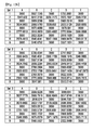
- FIGS. 11 a and 11 b show the sensitivity correction method sensed by applying the same pressure to all of the points as comparison targets.
- FIGS. 11 a and 11 b show the capacitance change amount of the touch input device when the correction is not made.
- FIG. 11 a can be understood as a graph corresponding to FIG. 3 .
- the horizontal axis of FIG. 11 a represents the measurement position.
- the numbers of the horizontal axis are set in the manner of sequentially scanning each row of FIG. 11 b .
- (1,A), (1,B), (1,C), (1,D), and (1,E) of FIG. 11 b correspond to 1, 2, 3, 4, and 5 listed on the horizontal axis of FIG. 11 a respectively.
- (2,A), (2,B), (2,C), (2,D), and (2,E) of FIG. 11 b correspond to 6, 7, 8, 9, and 10 listed on the horizontal axis of FIG. 11 a respectively.
- the position of each cell of FIG. 11 b may correspond to the position of the touch sensor panel 100 .
- FIGS. 12 a and 12 b show the capacitance change amount after the touch pressure sensitivity correction is made according to the embodiment of the present invention. Particularly, as shown in FIG. 5 a , FIGS. 12 a and 12 b show that the 15 reference points are defined and then the correction factor is finally calculated.
- cells of (1,A), (1,C), (1,E), (3,A), (3,C), (3,E), (5,A), (5,C), (5,E), (7,A), (7,C), (7,E), (9,A), (9,C), and (9,E) have all the target value of 3000.
- the cell corresponds to the reference point at which the capacitance change amount has been directly sensed.
- the cell has the target value of 3000 as it is because the correction factor obtained by multiplying the inverse number of the capacitance change amount by the target value is multiplied by the capacitance change amount again.
- FIGS. 13 a and 13 b show the capacitance change amount after the touch pressure sensitivity correction is made according to the embodiment of the present invention. Particularly, as shown in FIG. 5 b , FIGS. 13 a and 13 b show that the 12 reference points are defined and then the correction factor is finally calculated.
- cells of (1,A), (1,C), (1,E), (4,A), (4,C), (4,E), (6,A), (6,C), (6,E), (9,A), (9,C), and (9,E) have all the target value of 3000.
- the cell corresponds to the reference point at which the capacitance change amount has been directly sensed.
- the cell has the target value of 3000 as it is because the correction factor obtained by multiplying the inverse number of the capacitance change amount by the target value is multiplied by the capacitance change amount again.
- FIG. 14 is a flowchart showing the first correction step (a preliminary correction step) which is applied to the touch pressure sensitivity correction method according to the embodiment of the present invention.
- a plurality of position points are defined on the touch sensor panel included in a plurality of the touch input devices (S 210 ). While the sensitivity correction can be made only by one touch input device 1000 in the method of FIG. 4 described above, at least two touch input devices 100 are required to perform the first correction.
- the capacitance change amount is sensed by applying the same pressure (S 220 ).
- the step S 220 is performed on the plurality of the touch input devices, and the capacitance change amount at mutually corresponding is extracted in each touch input device, and then an average value thereof is calculated.
- the average value of the capacitance change amount for all the position points can be calculated and an average value data is generated based on the average value (S 230 ).
- the generated average value data is used to calculate a first correction factor for the first correction (S 240 ).
- the first correction factor may be an inverse number of the average value or may be a value obtained by multiplying the inverse number by the target value.
- the sensitivity of the touch input device is corrected by applying the first calculated correction factor to the plurality of the position points (S 250 ).
- the position point may correspond to the reference point and random point which are defined in the manner of FIG. 4 . That is, when the 15 reference points and 30 random points are defined in the manner of FIG. 4 , the position point may be also disposed in the areas where the 15 reference points and 30 random points are located. Also, when the 12 reference points and 33 random points are defined, the position point may be also disposed in the areas where the 12 reference points and 33 random points are located.
- the same pressure is applied to the plurality of the position points.
- the pressure which is applied to each of the position points should have a similar magnitude to that of a human finger.
- the capacitance change amount for the applied pressure is detected. Since the detection of the capacitance change amount has been described above, the description thereof will be omitted.
- the capacitance change amount for each position point may be detected.
- Three data shown in FIG. 11 b represent the capacitance change amounts detected from the three touch input devices respectively.
- the average value of the capacitance change amounts (capacitance change amounts recorded in the same cell) corresponding to the same position point is calculated and then the average value data is generated.
- the first correction factor for each position point is calculated based on the average value data.
- the first correction factor may be an inverse number of the average value calculated for each position point or may have a value obtained by multiplying the inverse number by the target value.
- the first calculated correction factor is used to primarily correct the sensitivity of the touch input device.
- the correction of the primarily corrected sensitivity of the touch input device is made again by performing again the substantive correction steps (S 110 to S 150 of FIG. 4 ).
- FIGS. 15 a and 15 b are a graph and data showing the sensitivity of the touch input device, to which the first correction has been applied.
- a graph which is much more uniform than the graph before the correction can be obtained. This means that the sensitivity of the touch input device becomes uniform through the first correction.
- FIGS. 16 a and 16 b show the capacitance change amount at each position point (reference point and random point) when the substantive correction steps (S 110 to S 150 of FIG. 4 ) has been performed one more time after the first correction is made. Particularly, FIGS. 16 a and 16 b show that the correction is made when the 15 reference points and the 30 random points are set.
- the touch input device which has performed both of the first correction and the substantive correction has a more uniform pressure touch sensitivity.
- FIGS. 17 a and 17 b show the capacitance change amount at each position point (reference point and random point) when the substantive correction steps (S 110 to S 150 of FIG. 4 ) has been performed one more time after the first correction is made. Particularly, FIGS. 17 a and 17 b show that the correction is made when the 12 reference points and the 33 random points are set.
- the touch input device which has performed both of the first correction and the substantive correction has a more uniform pressure touch sensitivity.
- the present invention may be implemented in the form of a computer-readable recording medium which records a program performing each of the steps included in the above-described touch pressure sensitivity correction method.
- the steps S 110 to S 150 can be performed by the program recorded in the recording medium according to the embodiment of the present invention.
- the program instruction which is recorded in the computer readable recording medium may be specially designed and configured for the present invention or may be well-known and available to those skilled in the field of computer software.
- the computer-readable recording medium may include a hardware device, for example, a magnetic medium such as a hard disk, a floppy disk, and a magnetic tape, an optical recording medium such as CD-ROM, DVD, a magneto-optical medium such as a floptical disk, and ROM, RAM, flash memory, etc., which is especially configured to store and perform program instructions.
- a hardware device for example, a magnetic medium such as a hard disk, a floppy disk, and a magnetic tape, an optical recording medium such as CD-ROM, DVD, a magneto-optical medium such as a floptical disk, and ROM, RAM, flash memory, etc., which is especially configured to store and perform program instructions.
- the program instruction may include not only a machine language code which is formed by a complier but also high-level language code which can be executed by a computer using an interpreter, etc.
- the hardware device may be configured to operate as one or more software modules in order to perform the process according to the present invention, and vice versa.
Landscapes
- Engineering & Computer Science (AREA)
- General Engineering & Computer Science (AREA)
- Theoretical Computer Science (AREA)
- Human Computer Interaction (AREA)
- Physics & Mathematics (AREA)
- General Physics & Mathematics (AREA)
- Position Input By Displaying (AREA)
Applications Claiming Priority (3)
| Application Number | Priority Date | Filing Date | Title |
|---|---|---|---|
| KR1020150104985A KR101762387B1 (ko) | 2015-07-24 | 2015-07-24 | 터치 압력 감도 보정 방법 및 컴퓨터 판독 가능한 기록 매체 |
| KR10-2015-0104985 | 2015-07-24 | ||
| PCT/KR2016/005563 WO2017018650A1 (ko) | 2015-07-24 | 2016-05-26 | 터치 압력 감도 보정 방법 및 컴퓨터 판독 가능한 기록 매체 |
Publications (2)
| Publication Number | Publication Date |
|---|---|
| US20180210599A1 US20180210599A1 (en) | 2018-07-26 |
| US10394364B2 true US10394364B2 (en) | 2019-08-27 |
Family
ID=57880838
Family Applications (1)
| Application Number | Title | Priority Date | Filing Date |
|---|---|---|---|
| US15/745,752 Active US10394364B2 (en) | 2015-07-24 | 2016-05-26 | Touch pressure sensitivity correction method and computer-readable recording medium |
Country Status (6)
| Country | Link |
|---|---|
| US (1) | US10394364B2 (ja) |
| EP (1) | EP3327559A4 (ja) |
| JP (1) | JP6514824B2 (ja) |
| KR (1) | KR101762387B1 (ja) |
| CN (1) | CN106371647B (ja) |
| WO (1) | WO2017018650A1 (ja) |
Families Citing this family (7)
| Publication number | Priority date | Publication date | Assignee | Title |
|---|---|---|---|---|
| CN107131982B (zh) * | 2017-05-12 | 2019-09-13 | 上海天马微电子有限公司 | 触控面板的触控压力检测方法 |
| CN109117014B (zh) * | 2017-06-26 | 2022-05-10 | 敦泰电子有限公司 | 一种电容式压力感应面板的压力校正方法和系统 |
| JP2019021144A (ja) * | 2017-07-19 | 2019-02-07 | 株式会社デンソーテン | 制御装置、制御方法および入力装置 |
| CN110703947B (zh) * | 2019-09-30 | 2022-09-02 | Oppo(重庆)智能科技有限公司 | 触摸屏校正方法及装置、电子设备以及存储介质 |
| CN112764564B (zh) * | 2019-10-21 | 2022-10-21 | Oppo广东移动通信有限公司 | 触控信息的处理方法、装置、存储介质及电子设备 |
| CN111522469B (zh) | 2020-05-06 | 2021-08-20 | 北京集创北方科技股份有限公司 | 触摸电容数据的调整方法及装置、电子设备、存储介质 |
| TWI786718B (zh) * | 2021-07-09 | 2022-12-11 | 義隆電子股份有限公司 | 觸控板及其力感應資訊校正方法 |
Citations (11)
| Publication number | Priority date | Publication date | Assignee | Title |
|---|---|---|---|---|
| US20090066673A1 (en) | 2007-09-07 | 2009-03-12 | Molne Anders L | Integrated force sensitive lens and software |
| KR20110134155A (ko) | 2010-06-08 | 2011-12-14 | 주식회사 켐트로닉스 | 터치 감지 장치에서 터치 감지부의 감도 설정 장치 및 그 방법, 및 이를 구현하기 위한 프로그램이 기록된 기록매체 |
| WO2012050875A1 (en) | 2010-10-12 | 2012-04-19 | Cypress Semiconductor Corporation | Force sensing capacitive hybrid touch sensor |
| JP2012103995A (ja) | 2010-11-12 | 2012-05-31 | Nissan Motor Co Ltd | タッチパネル装置およびタッチパネル装置の検出感度調整方法 |
| US20130082973A1 (en) | 2011-09-30 | 2013-04-04 | Apple Inc. | Display deformation detection |
| JP2013097628A (ja) | 2011-11-01 | 2013-05-20 | Alps Electric Co Ltd | 入力装置及びキャリブレーション方法 |
| KR20130060716A (ko) | 2011-11-30 | 2013-06-10 | 삼성전자주식회사 | 압력 센서를 구비한 터치 입력 장치 및 방법 |
| WO2014073586A1 (ja) | 2012-11-07 | 2014-05-15 | シャープ株式会社 | タッチパネルシステム |
| US20140225874A1 (en) | 2013-02-11 | 2014-08-14 | Texas Instruments Incorporated | Touch panel apparatus and methods |
| US20150049064A1 (en) | 2013-08-19 | 2015-02-19 | Samsung Display Co., Ltd. | Method of calibrating sensitivity of a touch input device and touch input device employing the same |
| CN106201053A (zh) | 2015-05-29 | 2016-12-07 | 高深公司 | 检测触摸压力的触摸输入装置的灵敏度修正方法及计算机可读记录介质 |
Family Cites Families (14)
| Publication number | Priority date | Publication date | Assignee | Title |
|---|---|---|---|---|
| JPH06332607A (ja) * | 1993-05-19 | 1994-12-02 | Mitsubishi Electric Corp | 表示一体型入力装置 |
| US7591165B2 (en) * | 2006-03-29 | 2009-09-22 | Tekscan Incorporated | Control circuit for sensor array and related methods |
| FR2941031B1 (fr) * | 2009-01-14 | 2011-02-11 | Areva Np | Obturateur etanche d'une ouverture d'une tubulure de jonction d'une enceinte et d'une canalisation et procede pour la mise en oeuvre d'un tel obturateur |
| EP2369580B1 (de) * | 2010-03-24 | 2014-04-02 | Goodbuy Corporation S.A. | Wirbel für ein Saiteninstrument |
| JP5625669B2 (ja) * | 2010-09-17 | 2014-11-19 | ソニー株式会社 | センサ装置および情報処理装置 |
| JP2012198607A (ja) * | 2011-03-18 | 2012-10-18 | Sony Corp | 座標補正関数生成装置、入力装置、座標補正関数生成方法、座標補正方法、及びプログラム |
| JP5220886B2 (ja) * | 2011-05-13 | 2013-06-26 | シャープ株式会社 | タッチパネル装置、表示装置、タッチパネル装置のキャリブレーション方法、プログラムおよび記録媒体 |
| JP2013025759A (ja) * | 2011-07-26 | 2013-02-04 | Kyocera Document Solutions Inc | 位置検出装置 |
| JP5861439B2 (ja) * | 2011-12-19 | 2016-02-16 | ミツミ電機株式会社 | 押圧力検出装置 |
| KR20130078116A (ko) * | 2011-12-30 | 2013-07-10 | 엘지디스플레이 주식회사 | 보간법을 이용한 터치 센서 구동 장치 및 방법 |
| US20130222336A1 (en) * | 2012-02-24 | 2013-08-29 | Texas Instruments Incorporated | Compensated Linear Interpolation of Capacitive Sensors of Capacitive Touch Screens |
| JP5865766B2 (ja) * | 2012-04-06 | 2016-02-17 | アルプス電気株式会社 | 入力装置及び押圧点検出方法 |
| JP5506982B1 (ja) * | 2013-05-31 | 2014-05-28 | 富士ソフト株式会社 | タッチ入力装置、タッチ入力補正方法、およびコンピュータプログラム |
| TWI489327B (zh) * | 2013-07-25 | 2015-06-21 | Waltop Int Corp | 電磁感應壓力階度的修正方法 |
-
2015
- 2015-07-24 KR KR1020150104985A patent/KR101762387B1/ko active IP Right Grant
- 2015-12-07 CN CN201510888392.4A patent/CN106371647B/zh active Active
-
2016
- 2016-05-26 US US15/745,752 patent/US10394364B2/en active Active
- 2016-05-26 WO PCT/KR2016/005563 patent/WO2017018650A1/ko active Application Filing
- 2016-05-26 JP JP2018502659A patent/JP6514824B2/ja active Active
- 2016-05-26 EP EP16830683.5A patent/EP3327559A4/en active Pending
Patent Citations (14)
| Publication number | Priority date | Publication date | Assignee | Title |
|---|---|---|---|---|
| US20090066673A1 (en) | 2007-09-07 | 2009-03-12 | Molne Anders L | Integrated force sensitive lens and software |
| KR20110134155A (ko) | 2010-06-08 | 2011-12-14 | 주식회사 켐트로닉스 | 터치 감지 장치에서 터치 감지부의 감도 설정 장치 및 그 방법, 및 이를 구현하기 위한 프로그램이 기록된 기록매체 |
| WO2012050875A1 (en) | 2010-10-12 | 2012-04-19 | Cypress Semiconductor Corporation | Force sensing capacitive hybrid touch sensor |
| JP2012103995A (ja) | 2010-11-12 | 2012-05-31 | Nissan Motor Co Ltd | タッチパネル装置およびタッチパネル装置の検出感度調整方法 |
| KR20140068257A (ko) | 2011-09-30 | 2014-06-05 | 애플 인크. | 디스플레이 변형 검출 |
| US20130082973A1 (en) | 2011-09-30 | 2013-04-04 | Apple Inc. | Display deformation detection |
| JP2013097628A (ja) | 2011-11-01 | 2013-05-20 | Alps Electric Co Ltd | 入力装置及びキャリブレーション方法 |
| KR20130060716A (ko) | 2011-11-30 | 2013-06-10 | 삼성전자주식회사 | 압력 센서를 구비한 터치 입력 장치 및 방법 |
| WO2014073586A1 (ja) | 2012-11-07 | 2014-05-15 | シャープ株式会社 | タッチパネルシステム |
| US20140225874A1 (en) | 2013-02-11 | 2014-08-14 | Texas Instruments Incorporated | Touch panel apparatus and methods |
| US20150049064A1 (en) | 2013-08-19 | 2015-02-19 | Samsung Display Co., Ltd. | Method of calibrating sensitivity of a touch input device and touch input device employing the same |
| KR20150020774A (ko) | 2013-08-19 | 2015-02-27 | 삼성디스플레이 주식회사 | 터치 입력 장치의 감도 보정 방법 및 이를 채용한 터치 입력 장치 |
| CN106201053A (zh) | 2015-05-29 | 2016-12-07 | 高深公司 | 检测触摸压力的触摸输入装置的灵敏度修正方法及计算机可读记录介质 |
| US20180088721A1 (en) | 2015-05-29 | 2018-03-29 | Hideep Inc. | Method for correcting sensitivity of touch input device that detects touch pressure and computer-readable recording medium |
Non-Patent Citations (5)
| Title |
|---|
| Chinese Office Action dated Oct. 8, 2018. |
| European Search Report for Related Application EP 16830683, dated Feb. 4, 2019. |
| International Search Report for corresponding PCT/KR2016/00563, dated Sep. 23, 2016. WO. |
| Japanese Office Action for Related Application No. JP 2018-502659, dated Nov. 27, 2018. |
| Machine Translation of JP 2012103995 (Year: 2019). * |
Also Published As
| Publication number | Publication date |
|---|---|
| KR101762387B1 (ko) | 2017-07-28 |
| CN106371647A (zh) | 2017-02-01 |
| WO2017018650A1 (ko) | 2017-02-02 |
| CN106371647B (zh) | 2019-08-02 |
| JP2018525732A (ja) | 2018-09-06 |
| EP3327559A4 (en) | 2019-03-13 |
| KR20170011764A (ko) | 2017-02-02 |
| EP3327559A1 (en) | 2018-05-30 |
| US20180210599A1 (en) | 2018-07-26 |
| JP6514824B2 (ja) | 2019-05-15 |
Similar Documents
| Publication | Publication Date | Title |
|---|---|---|
| US10394364B2 (en) | Touch pressure sensitivity correction method and computer-readable recording medium | |
| US10234987B2 (en) | Electrode sheet and touch input device | |
| US10331256B2 (en) | Method for correcting sensitivity of touch input device that detects touch pressure and computer-readable recording medium | |
| US10331268B2 (en) | Method for calibrating sensitivity of touch input devices sensing touch pressure, and computer readable recording medium | |
| US20160035290A1 (en) | Smartphone | |
| US20120146935A1 (en) | System and method for determining object information using an estimated rigid motion response | |
| US9465456B2 (en) | Reduce stylus tip wobble when coupled to capacitive sensor | |
| US10627951B2 (en) | Touch-pressure sensitivity correction method and computer-readable recording medium | |
| US20140043252A1 (en) | Touchscreen panel and touchscreen device | |
| KR101780260B1 (ko) | 터치 압력을 감지하는 터치 입력 장치의 감도 보정 방법 및 컴퓨터 판독 가능한 기록 매체 | |
| KR20170088807A (ko) | 터치 압력 감도 보정 방법 및 컴퓨터 판독 가능한 기록 매체 | |
| US10108303B2 (en) | Combining trans-capacitance data with absolute-capacitance data for touch force estimates | |
| US10088942B2 (en) | Per-finger force detection using segmented sensor electrodes | |
| US20190064966A1 (en) | Touch sensor panel | |
| US20190302947A1 (en) | Method for correcting sensitivity of touch input device that detects touch pressure and computer-readable recording medium | |
| US11016623B2 (en) | Touch sensor panel |
Legal Events
| Date | Code | Title | Description |
|---|---|---|---|
| AS | Assignment |
Owner name: HIDEEP INC., KOREA, REPUBLIC OF Free format text: ASSIGNMENT OF ASSIGNORS INTEREST;ASSIGNORS:SEO, BONG JIN;MOON, HO JUN;JIN, MYUNG JUN;AND OTHERS;REEL/FRAME:044652/0449 Effective date: 20171227 |
|
| FEPP | Fee payment procedure |
Free format text: ENTITY STATUS SET TO UNDISCOUNTED (ORIGINAL EVENT CODE: BIG.); ENTITY STATUS OF PATENT OWNER: SMALL ENTITY |
|
| FEPP | Fee payment procedure |
Free format text: ENTITY STATUS SET TO SMALL (ORIGINAL EVENT CODE: SMAL); ENTITY STATUS OF PATENT OWNER: SMALL ENTITY |
|
| STPP | Information on status: patent application and granting procedure in general |
Free format text: NON FINAL ACTION MAILED |
|
| STPP | Information on status: patent application and granting procedure in general |
Free format text: RESPONSE TO NON-FINAL OFFICE ACTION ENTERED AND FORWARDED TO EXAMINER |
|
| STPP | Information on status: patent application and granting procedure in general |
Free format text: NOTICE OF ALLOWANCE MAILED -- APPLICATION RECEIVED IN OFFICE OF PUBLICATIONS |
|
| STPP | Information on status: patent application and granting procedure in general |
Free format text: PUBLICATIONS -- ISSUE FEE PAYMENT VERIFIED |
|
| STCF | Information on status: patent grant |
Free format text: PATENTED CASE |
|
| MAFP | Maintenance fee payment |
Free format text: PAYMENT OF MAINTENANCE FEE, 4TH YR, SMALL ENTITY (ORIGINAL EVENT CODE: M2551); ENTITY STATUS OF PATENT OWNER: SMALL ENTITY Year of fee payment: 4 |