US10383648B2 - Steerable medical device - Google Patents
Steerable medical device Download PDFInfo
- Publication number
- US10383648B2 US10383648B2 US14/765,842 US201414765842A US10383648B2 US 10383648 B2 US10383648 B2 US 10383648B2 US 201414765842 A US201414765842 A US 201414765842A US 10383648 B2 US10383648 B2 US 10383648B2
- Authority
- US
- United States
- Prior art keywords
- medical device
- control wire
- elongated
- device body
- wire guides
- Prior art date
- Legal status (The legal status is an assumption and is not a legal conclusion. Google has not performed a legal analysis and makes no representation as to the accuracy of the status listed.)
- Active, expires
Links
Images


Classifications
-
- A—HUMAN NECESSITIES
- A61—MEDICAL OR VETERINARY SCIENCE; HYGIENE
- A61B—DIAGNOSIS; SURGERY; IDENTIFICATION
- A61B17/00—Surgical instruments, devices or methods, e.g. tourniquets
- A61B17/28—Surgical forceps
- A61B17/29—Forceps for use in minimally invasive surgery
-
- A—HUMAN NECESSITIES
- A61—MEDICAL OR VETERINARY SCIENCE; HYGIENE
- A61B—DIAGNOSIS; SURGERY; IDENTIFICATION
- A61B17/00—Surgical instruments, devices or methods, e.g. tourniquets
- A61B17/00234—Surgical instruments, devices or methods, e.g. tourniquets for minimally invasive surgery
-
- A—HUMAN NECESSITIES
- A61—MEDICAL OR VETERINARY SCIENCE; HYGIENE
- A61B—DIAGNOSIS; SURGERY; IDENTIFICATION
- A61B17/00—Surgical instruments, devices or methods, e.g. tourniquets
- A61B17/32—Surgical cutting instruments
-
- A—HUMAN NECESSITIES
- A61—MEDICAL OR VETERINARY SCIENCE; HYGIENE
- A61B—DIAGNOSIS; SURGERY; IDENTIFICATION
- A61B34/00—Computer-aided surgery; Manipulators or robots specially adapted for use in surgery
- A61B34/70—Manipulators specially adapted for use in surgery
- A61B34/71—Manipulators operated by drive cable mechanisms
-
- A—HUMAN NECESSITIES
- A61—MEDICAL OR VETERINARY SCIENCE; HYGIENE
- A61B—DIAGNOSIS; SURGERY; IDENTIFICATION
- A61B1/00—Instruments for performing medical examinations of the interior of cavities or tubes of the body by visual or photographical inspection, e.g. endoscopes; Illuminating arrangements therefor
- A61B1/005—Flexible endoscopes
- A61B1/0051—Flexible endoscopes with controlled bending of insertion part
- A61B1/0055—Constructional details of insertion parts, e.g. vertebral elements
-
- A—HUMAN NECESSITIES
- A61—MEDICAL OR VETERINARY SCIENCE; HYGIENE
- A61B—DIAGNOSIS; SURGERY; IDENTIFICATION
- A61B1/00—Instruments for performing medical examinations of the interior of cavities or tubes of the body by visual or photographical inspection, e.g. endoscopes; Illuminating arrangements therefor
- A61B1/005—Flexible endoscopes
- A61B1/008—Articulations
-
- A—HUMAN NECESSITIES
- A61—MEDICAL OR VETERINARY SCIENCE; HYGIENE
- A61B—DIAGNOSIS; SURGERY; IDENTIFICATION
- A61B17/00—Surgical instruments, devices or methods, e.g. tourniquets
- A61B17/00234—Surgical instruments, devices or methods, e.g. tourniquets for minimally invasive surgery
- A61B2017/00292—Surgical instruments, devices or methods, e.g. tourniquets for minimally invasive surgery mounted on or guided by flexible, e.g. catheter-like, means
- A61B2017/003—Steerable
- A61B2017/00305—Constructional details of the flexible means
- A61B2017/00314—Separate linked members
-
- A—HUMAN NECESSITIES
- A61—MEDICAL OR VETERINARY SCIENCE; HYGIENE
- A61B—DIAGNOSIS; SURGERY; IDENTIFICATION
- A61B17/00—Surgical instruments, devices or methods, e.g. tourniquets
- A61B17/00234—Surgical instruments, devices or methods, e.g. tourniquets for minimally invasive surgery
- A61B2017/00292—Surgical instruments, devices or methods, e.g. tourniquets for minimally invasive surgery mounted on or guided by flexible, e.g. catheter-like, means
- A61B2017/003—Steerable
- A61B2017/00318—Steering mechanisms
- A61B2017/00323—Cables or rods
-
- A—HUMAN NECESSITIES
- A61—MEDICAL OR VETERINARY SCIENCE; HYGIENE
- A61B—DIAGNOSIS; SURGERY; IDENTIFICATION
- A61B17/00—Surgical instruments, devices or methods, e.g. tourniquets
- A61B17/28—Surgical forceps
- A61B17/29—Forceps for use in minimally invasive surgery
- A61B2017/2901—Details of shaft
- A61B2017/2906—Multiple forceps
-
- A—HUMAN NECESSITIES
- A61—MEDICAL OR VETERINARY SCIENCE; HYGIENE
- A61B—DIAGNOSIS; SURGERY; IDENTIFICATION
- A61B17/00—Surgical instruments, devices or methods, e.g. tourniquets
- A61B17/28—Surgical forceps
- A61B17/29—Forceps for use in minimally invasive surgery
- A61B2017/2926—Details of heads or jaws
- A61B2017/2927—Details of heads or jaws the angular position of the head being adjustable with respect to the shaft
-
- A—HUMAN NECESSITIES
- A61—MEDICAL OR VETERINARY SCIENCE; HYGIENE
- A61B—DIAGNOSIS; SURGERY; IDENTIFICATION
- A61B34/00—Computer-aided surgery; Manipulators or robots specially adapted for use in surgery
- A61B34/30—Surgical robots
- A61B2034/305—Details of wrist mechanisms at distal ends of robotic arms
- A61B2034/306—Wrists with multiple vertebrae
-
- A—HUMAN NECESSITIES
- A61—MEDICAL OR VETERINARY SCIENCE; HYGIENE
- A61M—DEVICES FOR INTRODUCING MEDIA INTO, OR ONTO, THE BODY; DEVICES FOR TRANSDUCING BODY MEDIA OR FOR TAKING MEDIA FROM THE BODY; DEVICES FOR PRODUCING OR ENDING SLEEP OR STUPOR
- A61M25/00—Catheters; Hollow probes
- A61M25/01—Introducing, guiding, advancing, emplacing or holding catheters
- A61M25/0105—Steering means as part of the catheter or advancing means; Markers for positioning
- A61M25/0133—Tip steering devices
- A61M25/0147—Tip steering devices with movable mechanical means, e.g. pull wires
Definitions
- the present invention relates to a steerable medical device and, more particularly, to a medical device which includes radially deployable control wire guides.
- Medical devices such as endoscopes and catheters are widely used in minimally invasive surgery for viewing or treating organs, cavities, passageways, and tissues.
- such devices include an elongated device body which is designed for delivering and positioning a distally-mounted instrument (e.g. scalpel, grasper or camera/camera lens) within a body cavity, vessel or tissue.
- a distally-mounted instrument e.g. scalpel, grasper or camera/camera lens
- the medical device or at least a portion thereof be steerable, or maneuverable inside the body using controls positioned outside the body (at the proximal end of the medical device). Such steering enables an operator to guide the device within the body and accurately position the distally-mounted instrument at an anatomical landmark.
- steerable medical devices In order to control deflection of a steerable portion of the device and thus steer the instrument mounted thereon, steerable medical devices typically employ one or more control wires which run the length of the device and terminate at the distal end of the steerable portion or at the distal tip.
- each control wire is connected to the user operated handle; pulling of the wire bends the device body and deflects the steerable portion with relation the pulled wire.
- steerable devices are known in the art, see for example, U.S. Pat. Nos. 2,498,692; 4,753,223; 6,126,649; 5,873,842; 7,481,793; 6,817,974; 7,682,307 and U.S. Pat. Application Publication No. 20090259141.
- a steerable medical device having a device body narrow enough for delivery through standard delivery ports and yet capable of providing wide angle steering of the deflectable portion within the body while minimizing the pull force required for such steering.
- a medical device comprising: (a) an elongated device body, at least a portion of which being steerable within a body of a subject via at least one control wire; and (b) a plurality of control wire guides disposed along the elongated device body, the wire guides being deployable to deflect the at least one control wire away from a longitudinal axis of the elongated device body.
- At least a portion of the elongated device body is composed of a plurality of segments.
- control wire guides form a part of the segments.
- control wire guides extend radially outward when the plurality of interlinked segments are longitudinally compressed.
- the medical device further comprises a tube for compressing the interlinked segments.
- control wire guides are attached to an external surface of the elongated device body.
- control wire guides are struts capable of pivoting away from a longitudinal axis of the elongated device body.
- the pivoting of the struts is effected by pulling of the at least one control wire.
- the medical device further comprises a tubular sheath for compressing the struts against the elongated device body, wherein removal of the sheath releases the struts to pivot away from a longitudinal axis of the elongated device body.
- the medical device further comprises a plurality of control wires, each being for deflecting the at least a portion of the elongated device body in a specific direction.
- each of the plurality of control wires is deflectable via a specific set of control wire guides of the plurality of control wire guides.
- a number, spacing and/or deflection distance of control wire guides of the specific set of control wire guides varies for each of the plurality of control wires.
- the plurality of segments are interlinked.
- the elongated device body includes a flexible tube positioned through each of the plurality of segments.
- the medical device further comprises a tissue manipulator attached to a distal end of the elongated device body.
- the tissue manipulator is a grasper, a tissue cutter, or a needle.
- medical system comprising: (a) a first medical device having an elongated device body, at least a portion of the elongated device body being characterized by a first cross sectional shape; (b) a second medical device having an elongated device body, at least a portion of the elongated device body being characterized by a second cross sectional shape; wherein the first cross sectional shape and the second cross sectional shape are selected so as to maximize packing of at least one of the first medical device and at least one second medical device within an over tube.
- a portion of the elongated device body of the first medical device and/or the second medical device is steerable within a body of a subject.
- the over tube is used for delivering the first medical device and the second medical device into a body cavity.
- each of the first medical device and the second medical device further comprises a tissue manipulator attached to a distal end of the elongated device body.
- the tissue manipulator of the first medical device is different than a tissue manipulator of the medical device.
- a method of treating a subject (a) delivering the medical device of claim 15 or the medical system of claim 20 into a body of the subject; and (b) using the tissue manipulator to surgically manipulate a target tissue thereby treating the subject.
- the present invention successfully addresses the shortcomings of the presently known configurations by providing a steerable medical device having a deflectable region being configured capable of angling more than 180 degrees with respect to a longitudinal axis of the device.
- FIGS. 1A-B illustrate one embodiment of the device of the present invention in delivery ( FIG. 1A ) and deployed ( FIG. 1B ) states.
- FIGS. 2A-B illustrate another embodiment of the device of the present invention showing a single segment with control wire guides in a delivery state ( FIG. 2A ) and a deployed device ( FIG. 2B ).
- FIGS. 3A-C illustrate another embodiment of the device of the present invention showing a single segment with control wire guides in a delivery state ( FIG. 3A ), a single segment in a deployed state ( FIG. 3B ) and a segment configuration that includes a return spring ( FIG. 3C ).
- FIGS. 4A-C illustrate a tissue grasper device composed of the segments shown in FIGS. 3A-B , shown in a delivery state ( FIG. 4A ), a deployed state ( FIG. 4B ), and a deflected state ( FIG. 4C ).
- FIGS. 5A-B illustrate a device having 2 separately deflectable regions which can be deflected in the same direction ( FIG. 5A ) or in opposite directions (zigzag, FIG. 5B ).
- FIGS. 6A-D illustrate a system which includes several steerable devices configured for packing into a delivery tube.
- FIG. 6A is a cross section showing arrangement of the devices in the delivery tube;
- FIGS. 6B-C illustrate 2 configurations of steerable devices; and
- FIG. 6D illustrates coordinated use of several devices co-delivered through a delivery tube.
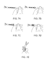
- FIGS. 7A-E illustrate deployment ( FIGS. 7A-D ) and steering ( FIG. 7E ) of a prototype device constructed in accordance with the teachings of the present invention.
- FIGS. 8A-B illustrate one embodiment of the present device showing the internal components of a handle ( FIG. 8A ), and the handle attached to the proximal end of the elongated body of the present device ( FIG. 8B ).
- FIGS. 9A-B illustrate a prototype of one configuration of the present device.
- the present invention is of a medical device and system which can be used in minimally invasive surgery. Specifically, the present invention can be used to provide enhanced steering.
- Steerable medical devices for use in minimally invasive surgery are well known in the art.
- Such devices typically utilize one or more control wires operable from a proximal end of the device positioned outside the body to deflect and thus steer a distal portion of the device positioned within the body.
- the longitudinal axis of the control wire In order to enable the control wire to efficiently deflect the distal portion of the device, the longitudinal axis of the control wire must be offset from the axis of deflection. In general, the greater the offset, the more deflection can be achieved with less pulling force applied to the control wire.
- the offset between the control wire and the deflection axis is in fact limited by the diameter of such port and the configuration of the device.
- the present inventor has devised a unique control wire guide configuration which enables greater separation between the longitudinal axis of the control wire and the deflection axis of the device thus enabling greater deflection while greatly reducing the pulling force required to achieve such deflection.
- a medical device which includes a steerable intrabody portion capable of being steered through a wide range of angles (up to 180 degrees and more) and patterns such as zigzag or varied diameter curves at one or more points along its length.
- the phrase “medical device” refers to any device utilizable in treatment of a subject, preferably a human subject.
- the medical device of the present invention is preferably used in minimally invasive surgery wherein a steerable distal portion thereof positioned within a body of a subject is controlled from a proximal end positioned outside the body (extra corporeally) via a control mechanism which preferably includes control wires.
- the medical device can be used for viewing or for manipulating tissues within any body cavity.
- Examples of medical devices which can benefit from the present invention include an endoscope (e.g. laparoscope or thorascope), a catheter, a needle holder, grasper, Scissors, hook, stapler, retractor and the like.
- the medical device of the present invention includes an elongated device body having a distal portion at least a portion of which is steerable within a body of a subject (also referred to herein as steerable portion), preferably via at least one control wire.
- the steerable portion of the device can be deflected in various directions and configurations, e.g. the entire steerable portion can be deflected (arced) towards one direction using a single control wire, or a first segment of the steerable portion can be deflected in one direction while another can be deflected in an opposite direction (zigzag) using two or more control wires.
- the elongated device body includes a plurality of control wire guides disposed along its length for routing one or more control wires from a proximal end of the elongated device body (which includes user controls, e.g. motorized or manual handle) to an end of a steerable portion thereof.
- a proximal end of the elongated device body which includes user controls, e.g. motorized or manual handle
- each control wire is routed to an end of a respective steerable portion.
- control wire guides are deployable to deflect a control wire carried thereby away from a longitudinal axis of the elongated device body. Deflection of the control wire away from the longitudinal axis of the device (radially outward) increases the offset between the control wire and the deflection axis of the elongated device body and thus provides a wider range of deflection angles while minimizing the pulling force needed to achieve deflection.
- the elongated device body is configured such that deployment of the control wire guides can be effected by a user following insertion of the distal portion of the device into the body.
- This enables delivery of the medical device of the present invention through a standard delivery port (e.g. 5, 8 or 10 mm trocar port).
- Such configurations can be used to enable deflection of the control wire away from the longitudinal axis of the elongated body.
- Such configurations preferably utilize control wire guides that move radially outward while also spacing the wire guides away from each other along the length of the elongated body. As is further described hereinbelow, such spacing increases the angulation capabilities of the elongated body.
- FIGS. 1 a -5 b illustrates several configurations of the present medical device which is referred to herein as device 10 .
- FIGS. 1 a - b illustrate an embodiment of device 10 which employs control wire guides configured as fold-out struts.
- Device 10 of FIGS. 1 a - b includes an elongated device body 12 (also referred to herein as elongated body 12 or body 12 ) which can include a deflectable portion 23 fabricated from a flexible tube or rod, or a series of segments 13 (as shown in FIG. 1 a - b ).
- elongated device body 12 also referred to herein as elongated body 12 or body 12
- deflectable portion 23 fabricated from a flexible tube or rod, or a series of segments 13 (as shown in FIG. 1 a - b ).
- Elongated device body 12 includes a user operable handle (see FIGS. 8 a - b for an example) attached to proximal end thereof and an effector end (e.g. tissue manipulator such as a grasper) attached to a distal end ( 44 in FIGS. 4 a -5 b ).
- the handle functions in controlling and setting an orientation and position of elongated body 12 and in operating the effector end.
- a flexible tube/rod configuration of deflectable portion 23 can be fabricated from a polymer such as structural engineering polymer, polypropylene, polycarbonate and the like using molding or extrusion techniques.
- deflectable portion 23 can also include cutouts along one or more sides of the tube (e.g. such as those shown in U.S. Pat. No. 4,911,148).
- Elongated body 12 can be 20-40 cm in length and 2.5-12 mm in diameter. Elongated body 12 can be hollow or solid depending on the use of device 10 . For example, in cases where device 10 is used to steer an endoscopic camera, elongated body 12 can be hollow in order to enable routing of wires or fiber optic cables from a user operable end (handle) to a camera or lens mounted on a distal end of elongated device body. A hollow elongated body 12 can also be used to route wires for controlling an operation of a tissue manipulator head such as a grasper although it will be appreciated that such wires can also be routed on the external surface of elongated body 12 through dedicated guides.
- a tissue manipulator head such as a grasper
- Elongated body 12 also includes two or more control wire guides 18 which in this embodiment of device 10 are configured as pivoting struts 20 ( 5 shown).
- Struts 20 can be fabricated from a polymer or alloy and can be attached to elongated body 12 using well known approaches.
- struts 20 can be co-formed with elongated device body 12 by, for example, cutting out struts 20 from the sidewall of a tube-shaped elongated body.
- Struts 20 are folded against elongated body 12 (as shown in FIG. 1 a ) during delivery of device 10 through a delivery port and are capable of folding out and back to assume a deployed position (as shown in FIG. 1 b ) in which struts 20 are angled at about 90 degrees with respect to elongated device body 12 .
- Struts can be connected to elongated body 12 via an elastic or pivoting hinge 27 ; a backstop can be provided on elongated body 12 to stop backward movement of strut 20 at about 90 degrees, or alternatively, the hinge can be designed for such purposes.
- Struts 20 can be maintained folded against device body via a delivery over-tube or sheath or via a fastening mechanism. Alternatively, struts 20 can be spring loaded to assume a folded configuration. Struts 20 include holes 22 at a distal end thereof ( 2 shown for each strut 20 ) through which a control wire 24 (a pair of control wires 24 shown for each strut) can be threaded.
- Control wires 24 which can be threaded through one or more rows of struts 20 (one row shown).
- One or more control wires 24 (two shown), threaded from the user handle through a single row of struts 20 (positioned on one side of elongated body 12 in the embodiment of FIGS. 1 a - b ) to an attachment point 21 at an end of the steerable portion, enables single-sided deflection (towards the side of struts 20 ) of a steerable portion of elongated body 12 .
- Two or more control wires 24 threaded through two opposing rows enable bi-directional deflection. Any number of control wires can be used depending on the deflection direction and configuration desired.
- a device 10 having several deflectable portions each separately capable of bi-directional deflection is described hereinbelow with reference to FIGS. 5 a - b.
- Each strut 20 has a length L and a distance D from an adjacent strut 20 ( FIG. 1 b ).
- Length L can be for example in the range of 1-5 mm, whereas distance D can be for example anywhere from 3 to 6 mm.
- Length L determines a leverage provided by strut 20 on a deflection point or region in elongated body 12 (for example, a point in a center of a width of elongated body 12 between segments 13 ), a larger L provides more leverage since the distance between the wire supported by strut 20 and the center of elongated body 12 is larger.
- Distance D determines the maximum angle of deflection of elongated body 12 (from the longitudinal axis) at the region of struts 20 , a larger D enables a larger angle of deflection since contact between the tips of struts 20 will prevent further deflection.
- the force needed to angle the links of a steerable segment of device 10 depends on the elastic properties of the steerable segment, and the distance between control wire 24 and a width center point of the steerable segment. This distance increases from length d to length D when struts 20 are deployed.
- the ratio d/D indicates the reduction in force needed to angle the links of a steerable segment.
- Device 10 can be deployed by pushing it out of the over-tube within the body cavity, or alternatively, in the case where struts 20 are fastened to, or spring-loaded against, elongated body 12 , pulling of control wires 24 can release struts 20 and unfold them.
- Device 10 can further include a wire for actuating a tissue manipulator end such an actuating wire can thread through center hole 15 ( FIG. 2 a ) at each link 13 .
- FIGS. 2 a - b illustrate another embodiment of device 10 .
- device 10 includes an elongated body 12 ( FIG. 2 b ) which is composed of segments 13 attached to a tissue grasper 29 .
- Each segment 13 can be fabricated from an alloy (e.g. stainless steel) or a polymer with a diameter of 2.2 (folded) and 6.6 mm (deployed).
- Segments 13 can be interlinked via linkage elements or fixable or movably mounted on a single long flexible rod or the actuating wire and/or elastic sleeve.
- Segment 13 shown in FIG. 2 a includes a longitudinal opening 15 which can accommodate a flexible rod or tube or the actuating wire and/or elastic sleeve (not shown). Any number of segments 13 can be mounted in a series on the rod or tube. In the configuration shown in FIG. 2 b , four segments 13 are mounted on a rod or tube to form a deflectable region 23 of device 10 .
- Segments 13 include 4 deployable control wire guides 18 having holes 22 for control wires 24 . Wire guides 18 are shown in a delivery (closed) state in FIG. 2 a and in a deployed state in FIG. 2 b.
- Each segment 13 includes two interlocked portions, a proximal portion 17 and a distal portion 19 .
- a spring 25 pushes portions 17 and 19 away from each other and maintains wire guides 18 closed against segment 13 , alternatively, wire guides 18 can be wrapped with an elastic tube that would function as a spring to keep guides 18 in side link 13 .
- Control wires 24 are threaded through holes 22 from the handle of device 10 (not shown) to distal region 21 . When control wires 24 are pulled in the proximal direction, portions 17 and 19 of segments 13 are compressed against spring 25 and wire guides 18 are deployed radially outward thus deflecting outward the portion of control wires 24 spanning the deflectable region.
- proximal portion 17 of each segment 13 includes a four-sided wedge that resides within distal portion 19 and in contact with (and internal to) the internal end of wire guides 18 .
- the wedge slides further into distal portion 19 thus pushing wire guides 18 outward and out of segment 13 .
- guides 18 enable a user to pull each side of deflectable region 23 and thus steer it in any direction. Since the ends of segments 13 are rounded, and wire guides 18 of adjacent segments are distanced from each other, region 23 can be deflected more than 90 degrees in any direction. Such deflection can be used to position a tissue grasper 29 at anatomically constrained spaces, or loop a device around an organ, for example, loop a gastric band around a lower esophageal sphincter or fundus of a stomach.
- FIGS. 3 a - c illustrate yet another configuration of device 10 which includes discrete segment 13 mounted over a flexible core 31 which includes a flexible tube/rod 33 surrounded by a spring like element 35 .
- Each segment 13 includes a proximal portion 17 and a distal portion 19 connected via one or more pivoting linkage arms 37 (Four shown in FIGS. 3 a - c ) which serve as control wire guides 18 .
- Control wires 24 run through holes 22 provided through linkage arms 37 .
- linkage arms 37 When in a delivery state ( FIG. 3 a ) linkage arms 37 are linearized and lie flat against spring-like element 35 , while proximal and distal portions ( 17 and 19 respectively) are spaced apart.
- proximal and distal portions 17 and 19 respectively
- linkage arms 37 pivot at midpoint pivot 41 and endpoint pivots 43 and extend radially outward thereby distracting control wires 24 away from the longitudinal axis of elongated body 12 .
- Distal portion 19 can be pulled against proximal portion 17 by pulling on any one of control wires 24 or by pulling a separate deployment wire or by pushing proximal portion 17 towards distal portion 19 using internal tube 47 (shown in FIGS. 2 b , and 4 a - b ).
- segments 13 preferably include a spring 39 which is compressed when segments 13 are compressed (during deployment of linkage arms 37 ), releasing the deployment force (e.g. releasing a pull wire), spaces apart portions 17 and 19 thus returning linkage arms 37 to their linearized state.
- a spring 39 which is compressed when segments 13 are compressed (during deployment of linkage arms 37 ), releasing the deployment force (e.g. releasing a pull wire), spaces apart portions 17 and 19 thus returning linkage arms 37 to their linearized state.
- FIGS. 4 a - c illustrate a tissue manipulating device 10 which includes a deflectable region 23 composed of three segments 13 (similar to those shown in FIGS. 3 a - c but with 2 wire guides 18 per segment 13 ).
- Device 10 can be configured as an endoscope, catheter or any other configuration deliverable into a body cavity, a vessel, a tissue and the like.
- Device 10 includes a tissue manipulating head 44 —tissue grasper head shown.
- Head 44 includes linkage mechanism 46 , which is actuated via a dedicated wire 48 , which runs within elongated body 12 to the user handle.
- FIG. 4 a illustrates device 10 in a delivery state with linkage arms 37 lying flat against elongate body 12 and portions 17 and 19 spaced apart.
- pulling of control wires 24 or pushing internal tube 47 FIG. 2 b
- compresses segments 13 and deploys wires 24 radially outward FIG. 4 b
- Further pulling of one wire 24 top wire 24 in FIG. 4 b
- Deflection is maximized to contact between guides 18 as indicated by 50 in FIG. 4 c .
- the contact between guides 18 is used to keep the articulated joint in a rigid state both for pulling (against the tensioned control wires 24 ) or for pushing (against the body of levers 18 ).
- FIGS. 5 a - b illustrate a device 10 that employs 8 segments 13 forming 2 separate deflectable regions 23 and 23 ′.
- regions 23 and 23 ′ are separately deflectable via a pair of dedicated control wires 24 .
- a first pair of control wires 24 terminate at attachment points 52 (the distal most segment 13 of region 23 ), while a second pair of control wires 24 terminate at points 54 (the distal most segment 13 of region 23 ′).
- This enables a user to deflect both regions 23 and 23 ′ in the same direction ( FIG. 5 a ) enabling 180 degrees or more of deflection, or in opposite directions (zigzag, FIG. 5 b ).
- the latter enables insertion of the device ‘behind’ or around organs such as an intestine.
- the present invention provides a steerable medical device that can be deployed through standard delivery port and yet provides superior steerability especially in tight anatomical spaces while requiring far less activation force to steer.
- the medical device of the present invention is particularly advantages in procedures which require steering through tight anatomical spaces and/or steering around an organ.
- control wires 24 of device 10 are preferably actuated from the user end of device 10 using a handle or a hand held motorized tool.
- FIG. 8 a illustrates one handle configuration that can be used with the present device.
- FIG. 8 b illustrates the handle attached to the proximal end of elongated body 12 which includes a tissue manipulator 44 attached to its distal end.
- FIG. 8 a - b show handle 100 and related components.
- Handle 100 includes a handle housing 102 that contains shaft housing 104 .
- Shaft housing 104 contains flexible core 118 compensating mechanism 112 wires 120 and wire ends 122 .
- Wire ends 122 are locked into compensating mechanism 112 , through holes located at the circumstance of flexible core 118 .
- Wires 120 extend through struts 20 and are locked to an end strut or the distal end of elongated body 12 or tool tip housing.
- Handle housing 102 and shaft housing 104 forms a ball joint.
- shaft adapter 106 (hingedly locked to handle 102 through locking mechanism 130 ) is advanced in a distal direction to deploy struts 20 (to a deployed state set by the surgeon).
- compensating mechanism 112 moves in order to allow the deployment of the struts, while keeping the tension in wires 120 .
- the surgeon can then articulate the distal joint by exerting a force on handle 102 causing the flexible core 118 to bend which causes the pulling of wires on the longer side of flexible core 118 .
- the pulled wire pulls the distal end of elongated body 12 and angles elongated body 12 .
- central elastic element 114 and flexible core 118 return to their original state. The amount of deflection in flexible core 118 determines the pulling force on the control wire and the radius of angulation.
- the proximal end of push/pull rod 116 is connected to jaws button 108 (mounted on jaws button shaft 140 ) through pin 110 .
- jaws button 108 mounted on jaws button shaft 140
- the distal end ( 48 , FIG. 4 b ) of push/pull rod 116 actuates jaw levers ( 46 , FIG. 4 b ) which actuate jaws 44 .
- a spring 124 can be used to facilitate the forward movement of jaws button 108 .
- Rotating jaws button 108 rotates jaws 44 via pin 110 that transfers the rotation movement to the jaws via push/pull rod 116 .
- Device 10 of the present invention also provides advantages when using a motorized handle to steer elongated body 12 and actuate tissue manipulator 44 . Since the force needed to navigate elongated body 12 is substantially less than that need in prior art devices a smaller lighter motor that can be easily integrated into the handle can be used.
- Such a system which is referred to herein as system 10 is shown in FIGS. 6 a and d ).
- system 100 shown in FIGS. 6 a and 6 d includes one device 10 having 4 rows of guides 18 and hence 4 control wires 24 ( FIG. 6 b ), and four of device 10 which includes 2 rows of guides 18 and hence 2 control wires 24 ( FIG. 6 c ).
- Device 10 having 4 rows of guides 18 can be positioned in the middle of delivery tube 102 , while the four device 10 having 2 rows of guides each, can be positioned there around. This maximizes packing of the devices in delivery tube 102 and enables delivery of several steerable devices having one or more steering capabilities into a body cavity through a standard delivery port.
- Devices 10 of system 100 can be used separately, i.e. each can be manipulated separately, or as is shown in FIG. 6 d , devices 10 can be cooperatively manipulated (via a single system handle or five device-dedicated handles) to enable tissue manipulation not possible with a single device.
- Device 10 can be operated using a manual or motorized handle.
- a manually operated handle is illustrated in FIGS. 8 a - b above.
- FIGS. 7 a - e The configuration illustrated in FIGS. 7 a - e was fabricated using rapid prototype technology ( FIGS. 9 a - b ).
- Shaft and links body diameter was 7 mm when the struts are folded the tool can be inserted through port with inner canal having 7 mm diameter.
- the distance between the wire and center of the steerable segment is 8 mm.
- the steerable segment was easily articulated ( FIG. 9 b ) by pulling the control wires and the tissue grasper end was rotated and actuated using a central wire.
Priority Applications (1)
| Application Number | Priority Date | Filing Date | Title |
|---|---|---|---|
| US14/765,842 US10383648B2 (en) | 2013-02-17 | 2014-02-17 | Steerable medical device |
Applications Claiming Priority (3)
| Application Number | Priority Date | Filing Date | Title |
|---|---|---|---|
| US201361765745P | 2013-02-17 | 2013-02-17 | |
| PCT/IL2014/050224 WO2014125498A2 (fr) | 2013-02-17 | 2014-02-17 | Dispositif médical orientable |
| US14/765,842 US10383648B2 (en) | 2013-02-17 | 2014-02-17 | Steerable medical device |
Related Parent Applications (1)
| Application Number | Title | Priority Date | Filing Date |
|---|---|---|---|
| PCT/IL2014/050224 A-371-Of-International WO2014125498A2 (fr) | 2013-02-17 | 2014-02-17 | Dispositif médical orientable |
Related Child Applications (1)
| Application Number | Title | Priority Date | Filing Date |
|---|---|---|---|
| US16/413,660 Continuation US11324528B2 (en) | 2013-02-17 | 2019-05-16 | Steerable medical device |
Publications (2)
| Publication Number | Publication Date |
|---|---|
| US20150366572A1 US20150366572A1 (en) | 2015-12-24 |
| US10383648B2 true US10383648B2 (en) | 2019-08-20 |
Family
ID=51354637
Family Applications (2)
| Application Number | Title | Priority Date | Filing Date |
|---|---|---|---|
| US14/765,842 Active 2035-01-01 US10383648B2 (en) | 2013-02-17 | 2014-02-17 | Steerable medical device |
| US16/413,660 Active 2035-05-20 US11324528B2 (en) | 2013-02-17 | 2019-05-16 | Steerable medical device |
Family Applications After (1)
| Application Number | Title | Priority Date | Filing Date |
|---|---|---|---|
| US16/413,660 Active 2035-05-20 US11324528B2 (en) | 2013-02-17 | 2019-05-16 | Steerable medical device |
Country Status (16)
| Country | Link |
|---|---|
| US (2) | US10383648B2 (fr) |
| EP (1) | EP2956202B1 (fr) |
| JP (1) | JP6273298B2 (fr) |
| KR (1) | KR20150119931A (fr) |
| CN (1) | CN105073177B (fr) |
| BR (1) | BR112015019218A2 (fr) |
| CA (1) | CA2900314C (fr) |
| CY (1) | CY1120896T1 (fr) |
| DK (1) | DK2956202T3 (fr) |
| ES (1) | ES2689868T3 (fr) |
| HK (1) | HK1215206A1 (fr) |
| HR (1) | HRP20181561T1 (fr) |
| HU (1) | HUE040679T2 (fr) |
| MX (1) | MX363964B (fr) |
| PT (1) | PT2956202T (fr) |
| WO (1) | WO2014125498A2 (fr) |
Cited By (3)
| Publication number | Priority date | Publication date | Assignee | Title |
|---|---|---|---|---|
| USD930830S1 (en) * | 2019-01-25 | 2021-09-14 | Karl Storz Se & Co. Kg | Shaft attachable medical instrument |
| USD961074S1 (en) * | 2019-01-25 | 2022-08-16 | Karl Storz Se & Co. Kg | Shaft attachable medical instrument |
| USD966513S1 (en) * | 2019-01-25 | 2022-10-11 | Karl Storz Se & Co. Kg | Shaft attachable medical instrument |
Families Citing this family (12)
| Publication number | Priority date | Publication date | Assignee | Title |
|---|---|---|---|---|
| CA2900314C (fr) | 2013-02-17 | 2022-03-22 | Human Extensions Ltd. | Dispositif medical orientable |
| AU2015242144B2 (en) * | 2014-03-31 | 2019-05-02 | Human Extensions Ltd. | Steerable medical device |
| WO2016174596A1 (fr) * | 2015-04-27 | 2016-11-03 | Fondazione Istituto Italiano Di Tecnologia | Structure déployable à mémoire de forme comprenant une paire de systèmes robotisés du type continuum |
| JP6150962B1 (ja) * | 2015-07-17 | 2017-06-21 | オリンパス株式会社 | マニピュレータ |
| US10806489B2 (en) * | 2015-07-31 | 2020-10-20 | Purdue Research Foundation | Systems and methods for performing a surgical procedure |
| US10709324B2 (en) * | 2015-07-31 | 2020-07-14 | Purdue Research Foundation | Systems and methods for performing a surgical procedure |
| US11559190B2 (en) | 2017-05-03 | 2023-01-24 | Canon U.S.A., Inc. | Steerable medical device and method |
| AU2019326548B2 (en) * | 2018-08-24 | 2023-11-23 | Auris Health, Inc. | Manually and robotically controllable medical instruments |
| US11642185B2 (en) * | 2019-12-16 | 2023-05-09 | Purdue Research Foundation | Systems and methods for performing a surgical procedure |
| US11234704B2 (en) * | 2020-03-03 | 2022-02-01 | Covidien Lp | Cable-actuated adapter for surgical stapling instrument |
| CN112023226B (zh) * | 2020-11-04 | 2021-03-19 | 上海心玮医疗科技股份有限公司 | 一种可调弯导丝 |
| CN116195394B (zh) * | 2023-04-28 | 2023-07-25 | 吉林天朗新能源科技有限公司 | 一种用于牵引机械设备的广角转向机构和牵引装置 |
Citations (12)
| Publication number | Priority date | Publication date | Assignee | Title |
|---|---|---|---|---|
| US3631737A (en) | 1970-09-18 | 1972-01-04 | Nasa | Remote control manipulator for zero gravity environment |
| WO2003001986A2 (fr) | 2001-06-29 | 2003-01-09 | Intuitive Surgical, Inc. | Instrument chirurgical presentant un mecanisme de type poignet a plusieurs disques, actionne par cables, positionnable de maniere sure |
| WO2006026520A2 (fr) | 2004-08-31 | 2006-03-09 | Surgical Solutions Llc | Dispositif medical a arbre articule |
| US20060142789A1 (en) * | 2004-12-15 | 2006-06-29 | Wilson-Cook Medical Inc. | Method and apparatus for augmentation of a sphincter |
| WO2007038715A1 (fr) | 2005-09-27 | 2007-04-05 | Synecor, Llc | Interventions et dispositifs chirurgicaux transgastriques |
| WO2007127199A1 (fr) | 2006-04-24 | 2007-11-08 | Synecor, Llc | Canule opératoire et système de support pour procédures chirurgicales utilisant un accès par un orifice naturel |
| US20080051802A1 (en) | 2006-08-10 | 2008-02-28 | Novineon Healthcare Technology Partners Gmbh | Medical instrument |
| US20080091170A1 (en) | 2003-09-12 | 2008-04-17 | Vargas Jaime S | Cannula system for free-space navigation and method of use |
| US20110118543A1 (en) | 2009-11-14 | 2011-05-19 | SPI Surgical, Inc. | Surgical device |
| US20110213384A1 (en) * | 2008-10-31 | 2011-09-01 | Chang Wook Jeong | Surgical robot system having tool for minimally invasive surgery |
| US20120197239A1 (en) | 2011-01-31 | 2012-08-02 | Paul Smith | Endoscopic medical device with articulating joints |
| WO2014125498A2 (fr) | 2013-02-17 | 2014-08-21 | Human Extensions Ltd. | Dispositif médical orientable |
-
2014
- 2014-02-17 CA CA2900314A patent/CA2900314C/fr active Active
- 2014-02-17 BR BR112015019218A patent/BR112015019218A2/pt active Search and Examination
- 2014-02-17 CN CN201480008853.8A patent/CN105073177B/zh active Active
- 2014-02-17 ES ES14751646.2T patent/ES2689868T3/es active Active
- 2014-02-17 KR KR1020157025639A patent/KR20150119931A/ko not_active Application Discontinuation
- 2014-02-17 MX MX2015010593A patent/MX363964B/es active IP Right Grant
- 2014-02-17 DK DK14751646.2T patent/DK2956202T3/en active
- 2014-02-17 PT PT14751646T patent/PT2956202T/pt unknown
- 2014-02-17 JP JP2015557569A patent/JP6273298B2/ja active Active
- 2014-02-17 US US14/765,842 patent/US10383648B2/en active Active
- 2014-02-17 EP EP14751646.2A patent/EP2956202B1/fr active Active
- 2014-02-17 WO PCT/IL2014/050224 patent/WO2014125498A2/fr active Application Filing
- 2014-02-17 HU HUE14751646A patent/HUE040679T2/hu unknown
-
2016
- 2016-03-21 HK HK16103263.6A patent/HK1215206A1/zh unknown
-
2018
- 2018-10-02 HR HRP20181561TT patent/HRP20181561T1/hr unknown
- 2018-10-16 CY CY181101056T patent/CY1120896T1/el unknown
-
2019
- 2019-05-16 US US16/413,660 patent/US11324528B2/en active Active
Patent Citations (18)
| Publication number | Priority date | Publication date | Assignee | Title |
|---|---|---|---|---|
| US3631737A (en) | 1970-09-18 | 1972-01-04 | Nasa | Remote control manipulator for zero gravity environment |
| WO2003001986A2 (fr) | 2001-06-29 | 2003-01-09 | Intuitive Surgical, Inc. | Instrument chirurgical presentant un mecanisme de type poignet a plusieurs disques, actionne par cables, positionnable de maniere sure |
| US20030036748A1 (en) | 2001-06-29 | 2003-02-20 | Intuitive Surgical, Inc. | Surgical tool having positively positionable tendon-actuated multi-disk wrist joint |
| JP2005502398A (ja) | 2001-06-29 | 2005-01-27 | イントゥイティブ・サージカル・インコーポレーテッド | ポジティブに位置決め可能な腱駆動マルチ・ディスク手首ジョイントを有する外科器具 |
| US20080091170A1 (en) | 2003-09-12 | 2008-04-17 | Vargas Jaime S | Cannula system for free-space navigation and method of use |
| JP2008511404A (ja) | 2004-08-31 | 2008-04-17 | サージカル ソリューションズ リミテッド ライアビリティ カンパニー | 屈曲シャフトを有する医療器具 |
| WO2006026520A2 (fr) | 2004-08-31 | 2006-03-09 | Surgical Solutions Llc | Dispositif medical a arbre articule |
| US20060074407A1 (en) | 2004-08-31 | 2006-04-06 | Martin Padget | Medical device with articulating shaft |
| US20060142789A1 (en) * | 2004-12-15 | 2006-06-29 | Wilson-Cook Medical Inc. | Method and apparatus for augmentation of a sphincter |
| JP2009509669A (ja) | 2005-09-27 | 2009-03-12 | シネコー・エルエルシー | 胃横断手術デバイス及び処置 |
| WO2007038715A1 (fr) | 2005-09-27 | 2007-04-05 | Synecor, Llc | Interventions et dispositifs chirurgicaux transgastriques |
| WO2007127199A1 (fr) | 2006-04-24 | 2007-11-08 | Synecor, Llc | Canule opératoire et système de support pour procédures chirurgicales utilisant un accès par un orifice naturel |
| US20080051802A1 (en) | 2006-08-10 | 2008-02-28 | Novineon Healthcare Technology Partners Gmbh | Medical instrument |
| US20110213384A1 (en) * | 2008-10-31 | 2011-09-01 | Chang Wook Jeong | Surgical robot system having tool for minimally invasive surgery |
| US20110118543A1 (en) | 2009-11-14 | 2011-05-19 | SPI Surgical, Inc. | Surgical device |
| WO2011060124A2 (fr) | 2009-11-14 | 2011-05-19 | Dosher Jesse A | Dispositif chirurgical |
| US20120197239A1 (en) | 2011-01-31 | 2012-08-02 | Paul Smith | Endoscopic medical device with articulating joints |
| WO2014125498A2 (fr) | 2013-02-17 | 2014-08-21 | Human Extensions Ltd. | Dispositif médical orientable |
Non-Patent Citations (13)
| Title |
|---|
| Communication Pursuant to Article 94(3) EPC dated Aug. 22, 2017 From the European Patent Office Re. Application No. 14751646.2. (5 Pages). |
| Examination Report dated Jul. 25, 2018 From the Instituto Mexicano de la Propiedad Industrial, IMPI, Direccion Divisional de Patentes Re. Application No. MX/a/2015/010593 and Its Translation Into English. (6 Pages). |
| International Preliminary Report on Patentability dated Aug. 27, 2015 From the International Bureau of WIPO Re. Application No. PCT/IL2014/050224. |
| International Search Report and the Written Opinion dated Sep. 8, 2014 From the International Searching Authority Re. Application No. PCT/IL2014/050224. |
| Invitation to Pay Additional Fees dated Jun. 24, 2014 From the International Searching Authority Re. Application No. PCT/IL2014/050224. |
| Notice of Reason for Rejection dated Aug. 29, 2017 From the Japan Patent Office Re. Application No. 2015-557569 and Its Translation Into English. (2 Pages). |
| Notification of Office Action and Search Report dated Jan. 4, 2017 From the State Intellectual Property Office of the People's Republic of China Re. Application No. 201480008853.8 and Its Translation of Office Action Into English. (12 Pages). |
| Notification of Office Action and Search Report dated Nov. 29, 2017 From the State Intellectual Property Office of the People's Republic of China Re. Application No. 201480008853.8. (7 Pages). |
| Notification of Office Action dated Jun. 22, 2017 From the State Intellectual Property Office of the People's Republic of China Re. Application No. 201480008853.8 and Its Summary in English. (4 Pages). |
| Notification of Office Action dated May 2, 2018 From the State Intellectual Property Office of the People's Republic of China Re. Application No. 201480008853.8 and Its Translation Into English. (9 Pages). |
| Supplementary European Search Report and the European Search Opinion dated Sep. 7, 2016 From the European Patent Office Re. Application No. 14751646.2. |
| Translation of Notification of Office Action dated Jun. 22, 2017 From the State Intellectual Property Office of the People's Republic of China Re. Application No. 201480008853.8. (1 Page). |
| Translation of Notification of Office Action dated Nov. 29, 2017 From the State Intellectual Property Office of the People's Republic of China Re. Application No. 201480008853.8. (5 Pages). |
Cited By (3)
| Publication number | Priority date | Publication date | Assignee | Title |
|---|---|---|---|---|
| USD930830S1 (en) * | 2019-01-25 | 2021-09-14 | Karl Storz Se & Co. Kg | Shaft attachable medical instrument |
| USD961074S1 (en) * | 2019-01-25 | 2022-08-16 | Karl Storz Se & Co. Kg | Shaft attachable medical instrument |
| USD966513S1 (en) * | 2019-01-25 | 2022-10-11 | Karl Storz Se & Co. Kg | Shaft attachable medical instrument |
Also Published As
| Publication number | Publication date |
|---|---|
| US20150366572A1 (en) | 2015-12-24 |
| KR20150119931A (ko) | 2015-10-26 |
| HK1215206A1 (zh) | 2016-08-19 |
| MX2015010593A (es) | 2015-11-16 |
| PT2956202T (pt) | 2018-11-14 |
| MX363964B (es) | 2019-04-09 |
| HUE040679T2 (hu) | 2019-03-28 |
| WO2014125498A3 (fr) | 2014-10-30 |
| EP2956202B1 (fr) | 2018-07-25 |
| WO2014125498A2 (fr) | 2014-08-21 |
| EP2956202A2 (fr) | 2015-12-23 |
| BR112015019218A2 (pt) | 2017-08-22 |
| CY1120896T1 (el) | 2019-12-11 |
| JP6273298B2 (ja) | 2018-01-31 |
| JP2016513985A (ja) | 2016-05-19 |
| CN105073177B (zh) | 2018-10-12 |
| US11324528B2 (en) | 2022-05-10 |
| CA2900314A1 (fr) | 2014-08-21 |
| CN105073177A (zh) | 2015-11-18 |
| US20190262018A1 (en) | 2019-08-29 |
| CA2900314C (fr) | 2022-03-22 |
| DK2956202T3 (en) | 2018-11-19 |
| HRP20181561T1 (hr) | 2018-11-30 |
| EP2956202A4 (fr) | 2016-10-05 |
| ES2689868T3 (es) | 2018-11-16 |
Similar Documents
| Publication | Publication Date | Title |
|---|---|---|
| US11324528B2 (en) | Steerable medical device | |
| US11471026B2 (en) | System for a minimally-invasive, operative gastrointestinal treatment | |
| US20200352431A1 (en) | System for a minimally-invasive, operative gastrointestinal treatment background | |
| US20230320710A1 (en) | Steerable medical device | |
| JP4520976B2 (ja) | 管腔内ツール展開システム | |
| US10966701B2 (en) | Tissue retractor for minimally invasive surgery | |
| EP3256053A1 (fr) | Écarteur de tissu pour chirurgie mini-invasive | |
| JP2007513717A (ja) | 胃腸組織の襞を形成および固定するための装置および方法 | |
| JP2006516910A5 (fr) | ||
| US20220280032A1 (en) | Multi-lumen-catheter retractor system for a minimally-invasive, operative gastrointestinal treatment | |
| WO2021118958A1 (fr) | Dispositifs, systèmes et procédés pour chirurgie minimalement invasive à l'intérieur d'une lumière corporelle | |
| EP3457908B1 (fr) | Système pour un traitement gastro-intestinal chirurgical mini-invasif |
Legal Events
| Date | Code | Title | Description |
|---|---|---|---|
| AS | Assignment |
Owner name: HUMAN EXTENSIONS LTD., ISRAEL Free format text: ASSIGNMENT OF ASSIGNORS INTEREST;ASSIGNOR:SHOLEV, MORDEHAI;REEL/FRAME:036548/0481 Effective date: 20140120 |
|
| STPP | Information on status: patent application and granting procedure in general |
Free format text: NOTICE OF ALLOWANCE MAILED -- APPLICATION RECEIVED IN OFFICE OF PUBLICATIONS |
|
| STPP | Information on status: patent application and granting procedure in general |
Free format text: PUBLICATIONS -- ISSUE FEE PAYMENT RECEIVED |
|
| STPP | Information on status: patent application and granting procedure in general |
Free format text: PUBLICATIONS -- ISSUE FEE PAYMENT VERIFIED |
|
| STCF | Information on status: patent grant |
Free format text: PATENTED CASE |
|
| MAFP | Maintenance fee payment |
Free format text: PAYMENT OF MAINTENANCE FEE, 4TH YR, SMALL ENTITY (ORIGINAL EVENT CODE: M2551); ENTITY STATUS OF PATENT OWNER: SMALL ENTITY Year of fee payment: 4 |