US10312759B2 - Motor with elastic element deformable in different directions - Google Patents
Motor with elastic element deformable in different directions Download PDFInfo
- Publication number
- US10312759B2 US10312759B2 US15/374,368 US201615374368A US10312759B2 US 10312759 B2 US10312759 B2 US 10312759B2 US 201615374368 A US201615374368 A US 201615374368A US 10312759 B2 US10312759 B2 US 10312759B2
- Authority
- US
- United States
- Prior art keywords
- rotating shaft
- motor
- body shell
- rotor
- electromagnetic group
- Prior art date
- Legal status (The legal status is an assumption and is not a legal conclusion. Google has not performed a legal analysis and makes no representation as to the accuracy of the status listed.)
- Active, expires
Links
Images


Classifications
-
- H—ELECTRICITY
- H02—GENERATION; CONVERSION OR DISTRIBUTION OF ELECTRIC POWER
- H02K—DYNAMO-ELECTRIC MACHINES
- H02K1/00—Details of the magnetic circuit
- H02K1/06—Details of the magnetic circuit characterised by the shape, form or construction
- H02K1/34—Reciprocating, oscillating or vibrating parts of the magnetic circuit
-
- A—HUMAN NECESSITIES
- A61—MEDICAL OR VETERINARY SCIENCE; HYGIENE
- A61C—DENTISTRY; APPARATUS OR METHODS FOR ORAL OR DENTAL HYGIENE
- A61C17/00—Devices for cleaning, polishing, rinsing or drying teeth, teeth cavities or prostheses; Saliva removers; Dental appliances for receiving spittle
- A61C17/16—Power-driven cleaning or polishing devices
- A61C17/22—Power-driven cleaning or polishing devices with brushes, cushions, cups, or the like
- A61C17/32—Power-driven cleaning or polishing devices with brushes, cushions, cups, or the like reciprocating or oscillating
- A61C17/34—Power-driven cleaning or polishing devices with brushes, cushions, cups, or the like reciprocating or oscillating driven by electric motor
- A61C17/3409—Power-driven cleaning or polishing devices with brushes, cushions, cups, or the like reciprocating or oscillating driven by electric motor characterized by the movement of the brush body
- A61C17/3481—Vibrating brush body, e.g. by using eccentric weights
-
- H—ELECTRICITY
- H02—GENERATION; CONVERSION OR DISTRIBUTION OF ELECTRIC POWER
- H02K—DYNAMO-ELECTRIC MACHINES
- H02K1/00—Details of the magnetic circuit
- H02K1/06—Details of the magnetic circuit characterised by the shape, form or construction
- H02K1/12—Stationary parts of the magnetic circuit
- H02K1/14—Stator cores with salient poles
- H02K1/141—Stator cores with salient poles consisting of C-shaped cores
- H02K1/143—Stator cores with salient poles consisting of C-shaped cores of the horse-shoe type
-
- H—ELECTRICITY
- H02—GENERATION; CONVERSION OR DISTRIBUTION OF ELECTRIC POWER
- H02K—DYNAMO-ELECTRIC MACHINES
- H02K1/00—Details of the magnetic circuit
- H02K1/06—Details of the magnetic circuit characterised by the shape, form or construction
- H02K1/22—Rotating parts of the magnetic circuit
- H02K1/27—Rotor cores with permanent magnets
- H02K1/2706—Inner rotors
- H02K1/272—Inner rotors the magnetisation axis of the magnets being perpendicular to the rotor axis
- H02K1/2726—Inner rotors the magnetisation axis of the magnets being perpendicular to the rotor axis the rotor consisting of a single magnet or two or more axially juxtaposed single magnets
-
- H—ELECTRICITY
- H02—GENERATION; CONVERSION OR DISTRIBUTION OF ELECTRIC POWER
- H02K—DYNAMO-ELECTRIC MACHINES
- H02K33/00—Motors with reciprocating, oscillating or vibrating magnet, armature or coil system
- H02K33/02—Motors with reciprocating, oscillating or vibrating magnet, armature or coil system with armatures moved one way by energisation of a single coil system and returned by mechanical force, e.g. by springs
-
- H—ELECTRICITY
- H02—GENERATION; CONVERSION OR DISTRIBUTION OF ELECTRIC POWER
- H02K—DYNAMO-ELECTRIC MACHINES
- H02K7/00—Arrangements for handling mechanical energy structurally associated with dynamo-electric machines, e.g. structural association with mechanical driving motors or auxiliary dynamo-electric machines
- H02K7/003—Couplings; Details of shafts
Definitions
- the present invention relates to the field of electric motors, and particularly relates to a motor.
- Dental calculi as an important pathogenic factor of periodontal diseases, refers to dental plaque and debris which are mineralized or being mineralized on the dental face, and are composed of 75% of calcium phosphate, 15-25% of water, organic matters, manganese phosphate, mineral acid calcium as well as trace potassium, sodium and iron. It is difficult to clear the dental calculi with a common toothbrush, and the dental calculi are easily and quickly deposited on the surface of teeth again even if being thoroughly scaled in a stomatological hospital.
- the technical problem to be solved by the present invention is to provide a motor of which a rotor can move in multiple directions.
- an embodiment of the present invention provides a motor, including an enclosure, a stator and a rotor, the stator including a first electromagnetic group and a second electromagnetic group, the rotor being inserted between the first electromagnetic group and the second electromagnetic group, wherein the rotor includes a rotating shaft and a magnetic part installed around the outer wall of the rotating shaft, the motor further including:
- an elastic element with a first contact part fixed on a rear cover of the enclosure, and a second contact part connected with the rotating shaft, wherein the elastic element is elastically deformable in at least two different directions.
- the first contact part of the elastic element is installed in a groove of the rear cover.
- the tail end of the rotating shaft is provided with at least one clamping groove, and the second contact part of the elastic element is fixed at the tail end of the rotating shaft via the clamping groove.
- the elastic element is an S-shaped spring.
- the rear cover and the S-shaped spring are injection molded integrally.
- the rotor further includes a rotating shaft injection-molded part, which is used for integrally injection molding of the rotating shaft and the magnetic part installed around the outer wall of the rotating shaft.
- the magnetic part includes a first magnet, a second magnet, a first magnetic conductive plate and a second magnetic conductive plate;
- first magnet and the second magnet are respectively embedded into two opposite sides of the rotating shaft injection-molded part, and the first magnetic conductive plate and the second magnetic conductive plate are respectively fixed on the other two opposite sides of the rotating shaft injection-molded part and respectively in contact with the first magnet and the second magnet.
- the first electromagnetic group and the second electromagnetic group are symmetrically fixed to form a cavity, and the magnetic part of the rotor is inserted into the cavity;
- the first electromagnetic group includes a first magnetized part and a first coil wound on the first magnetized part
- the second electromagnetic group includes a second magnetized part and a second coil wound on the second magnetized part
- the enclosure further includes a first body shell, a second body shell and a front cover;
- the first body shell and the second body shell enclose the magnetic part from outside, the front cover is sleeved on the rotating shaft and connected with the front ends of the first body shell and the second body shell, and the rear cover is connected with the rear ends of the first body shell and the second body shell;
- the first body shell and the second body shell are respectively provided with a first installation groove, a second installation groove and electromagnetic group fixing parts, and through the electromagnetic group fixing parts, the first electromagnetic group is installed in the first installation groove and the second electromagnetic group is installed in the second installation groove.
- the rotating shaft is sleeved with a bearing, and the bearing is installed in a bearing groove of the front cover.
- clearances are formed between the tails of the first body shell and the second body shell and the rotating shaft.
- an elastic body is arranged in front of the clearances.
- the motor of the present invention is provided with an elastic element having elastic deformation in multiple directions, so that the rotating shaft of the motor can move in multiple directions, e.g., rotating left and right and vibrating up and down.
- the motor can be applied to an electric toothbrush, a shaver, a loudspeaker, an electric hammer, a stirrer, a refrigerator, a sewing machine, a packaging and bundling machine, an electromagnetic pump, etc.
- the rotating shaft of the toothbrush has the effects of high-frequency shimmy and high-frequency knocking vibration at the same time, and the dental calculi on the dental surface can be crushed via high-frequency knock, so that a higher cleaning effect is achieved.
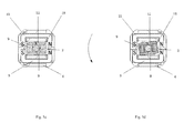
- FIG. 1 a shows a schematic structural diagram of a motor according to an embodiment of the present invention
- FIG. 1 b shows a schematic diagram of deformation directions of an elastic element of the motor according to an embodiment of the present invention
- FIGS. 2 a -2 d show schematic diagrams of the reset principle of an S-shaped spring according to another embodiment of the present invention.
- FIGS. 3 a -3 b show schematic structural diagrams of a rotor of the motor according to another embodiment of the present invention.
- FIGS. 4 a -4 b show schematic structural diagrams of a stator of the motor according to another embodiment of the present invention.
- FIGS. 5 a -5 d show schematic diagrams of the rotating principle of the rotor according to another embodiment of the present invention.
- FIG. 6 shows an exploded view of the motor according to another embodiment of the present invention.
- FIG. 7 shows a section view of the motor according to another embodiment of the present invention.
- FIG. 1 a shows a schematic structural diagram of a motor according to an embodiment of the present invention.
- the motor mainly includes an enclosure 100 , a stator 200 and a rotor 300 .
- the stator 200 includes a first electromagnetic group 210 and a second electromagnetic group 220
- the rotor 300 is inserted between the first electromagnetic group 210 and the second electromagnetic group 220
- the rotor 300 includes a rotating shaft 2 and a magnetic part 310 installed around the outer wall of the rotating shaft 2 .
- the motor further includes an elastic element (not shown in the figure), with a first contact part fixed on a rear cover 11 of the enclosure 100 , and a second contact part connected with the rotating shaft 2 , wherein the elastic element is elastically deformable in at least two different directions.
- the motor is an electromagnetic device for converting or transferring electric energy according to the law of electromagnetic induction, and is widely applied to electric equipment.
- the elastic element is the one with resilience, and can generate a restoring force during deformation thereof to restore its original shape.
- the stator 200 of the motor of this embodiment adopts two electromagnetic groups, and the magnetic part 310 of the rotor 300 is preferably a permanent magnet, so that the rotor 300 is lighter in weight and quick in dynamic response and has a larger output torque in the case of providing an equal ampere-turn current. Meanwhile, by adopting the above structure, the motor is more convenient to install and detach, and later maintenance cost can be reduced.
- the first contact part of the elastic element is installed in a groove of the rear cover 11 .
- the tail end of the rotating shaft 2 is provided with at least one clamping groove, and the second contact part of the elastic element is fixed at the tail end of the rotating shaft 2 via the clamping groove.
- the elastic element is preferably an S-shaped spring 10 , and as shown in FIG. 1 b , the S-shaped spring 10 is elastically deformable in at least two directions.
- the S-shaped spring 10 can be stretched or extruded in the first direction and the second direction.
- the first contact part of the S-shaped spring 10 includes a first end 10 A and a second end 10 B
- the rear cover 11 of the motor is provided with two symmetrical grooves
- the grooves have movable spaces
- the first end 10 A and the second end 10 B are respectively installed in the corresponding grooves.
- the S-shaped spring 10 and the rear cover 11 have an injection molded integrally structure.
- the second contact part of the S-shaped spring 10 is a middle rod 10 C thereof, the tail of the rotating shaft 2 is provided with a long clamping groove, the middle rod 10 C of the S-shaped spring 10 is fixed in the long clamping groove of the rotating shaft 2 , and the rotating shaft 2 and the S-shaped spring 10 are detachable.
- the tail cover 11 and the elastic element of the motor can be replaced, thereby prolonging the service life of the motor and reducing the cost.
- the rotor 300 inserted into the stator 200 rotates under the action of a magnetic thrust, and deviates from the initial axis.
- the rotating shaft 2 of the rotor 300 drives the S-shaped spring 10 to arrive at the position shown in FIG. 2 b .
- the S-shaped spring 10 is elastically deformed in two different directions as shown in FIG. 1 b .
- the rotor 300 can return to the initial position under the action of a restoring force in the two directions of the S-shaped spring 10 .
- the direction of the magnetic thrust can be changed by changing the current direction of the stator 200 , so that the rotor 300 rotates in the direction opposite to that of the previous phase and deviates from the initial axis.
- the rotor 300 drives the S-shaped spring 10 to arrive at the position shown in FIG. 2 d .
- the rotor 300 returns to the initial position again under the action of the restoring force in the two directions of the S-shaped spring 10 .
- the rotor 300 rotates reciprocally with certain amplitude and vibrates in the vertical direction of the rotating shaft 2 .
- the S-shaped spring 10 has the characteristics that the generated noise is low, the restoration is strong and the spring is easy to install. Specifically, two ends of the S-shaped spring 10 are bent in a non-semicircular arc manner, thereby improving the elastic restoration strength of the two ends. With different radians of the semicircular arc, the resulting flexibility and rigidity are different, and the performance is easy to control. Meanwhile, the S-shaped spring 10 is simple in installation process and good in location dimension, has good coaxial characteristic, and can well ensure the concentric position with the rotating shaft 2 .
- the S-shaped spring 10 adopted in this embodiment is merely an example, and an elastic element of other type, which is similar to the S-shaped spring 10 capable of elastic deformation in multiple directions, can also be adopted, e.g., an Z-shaped, M-shaped, X-shaped, U-shaped, I-shaped or N-shaped spring, etc.
- the motor of this embodiment is applicable to an electric toothbrush, a shaver, a loudspeaker, an electric hammer, a stirrer, a refrigerator, a sewing machine, a packaging and bundling machine, an electromagnetic pump, etc.
- the rotating shaft of the toothbrush has the effects of high-frequency shimmy and high-frequency knocking vibration at the same time, and the dental calculi on the dental surface can be crushed via high-frequency knock, so that a higher cleaning effect is achieved.
- FIGS. 3 a -3 b show schematic structural diagrams of the rotor 300 of the motor according to another embodiment of the present invention.
- the components with the same signs in FIGS. 3 a to 3 b , 1 a to 1 b and 2 a to 2 d have the same meanings, and thus are not redundantly described herein.
- the rotor 300 of the motor in this embodiment further includes a rotating shaft injection-molded part 21 , which is used for integrally injection molding of the rotating shaft 2 and the magnetic part 310 installed around the outer wall of the rotating shaft 2 .
- the rotating shaft 2 is preferably an integrated rod. By adopting the integrated rod structure, the stress of the rotating shaft 2 is more uniform, and the rotating shaft 2 is unlikely to break and also produces a smoother movement locus.
- the magnetic part 310 is installed around the outer wall of the rotating shaft 2 via the rotating shaft injection-molded part 21 .
- the magnetic part 310 includes a first magnet 9 , a second magnet 18 , a first magnetic conductive plate 8 and a second magnetic conductive plate 12 .
- the first magnet 9 and the second magnet 18 are respectively embedded into two opposite sides of the rotating shaft injection-molded part 21 .
- the first magnetic conductive plate 8 and the second magnetic conductive plate 12 are respectively fixed on the other two opposite sides of the rotating shaft injection-molded part 21 and respectively in contact with the first magnet 9 and the second magnet 18 .
- the first magnet 9 and the second magnet 18 which are in parallel and with consistent polarity directions, are respectively embedded into the two opposite sides of the rotating shaft injection-molded part 21 .
- the first magnetic conductive plate 8 and the second magnetic conductive plate 12 are respectively in contact with the first magnet 9 and the second magnet 18 and cover the contact faces.
- the rotating shaft 2 , the first magnet 9 , the second magnet 18 , the first magnetic conductive plate 8 and the second magnetic conductive plate 12 are fixed relative to each other into a whole, which can effectively keep the axis consistency of the motor.
- the first magnet 9 and the second magnet 18 are preferably permanent magnets
- the first magnetic conductive plate 8 and the second magnetic conductive plate 12 are preferably plate structures made of a magnetic conductive material
- each magnetic conductive plate is provided with through holes for installation on the rotating shaft injection-molded part 21
- the through holes can be sleeved on protrusions of the rotating shaft injection-molded part 21 .
- the shapes of the through holes and the protrusions are not limited, and can be square as shown in the figure or other shape.
- the two magnetic conductive plates can also be fixed on the rotating shaft injection-molded part 21 in other way such as bonding, riveting or the like, and this embodiment is not limited thereto.
- FIGS. 4 a -4 b show schematic structural diagrams of the stator 200 of the motor according to another embodiment of the present invention.
- the components with the same signs in FIGS. 4 a to 4 b , 1 a to 1 b , 2 a to 2 d and 3 a to 3 b have the same meanings, and thus are not redundantly described herein.
- the stator 200 includes a first electromagnetic group 210 and a second electromagnetic group 220 which are symmetrically fixed to form a cavity, and the magnetic part 310 of the rotor 300 is inserted into the cavity.
- the first electromagnetic group 210 includes a first magnetized part 5 and a first coil 4 wound on the first magnetized part 5
- the second electromagnetic group includes a second magnetized part 15 and a second coil 14 wound on the second magnetized part 15 .
- the first magnetized part 5 and the second magnetized part 15 can be made of a magnetized material such as silicon steel or the like.
- a magnetized material such as silicon steel or the like.
- two silicon steel sheets (the first magnetized part 5 and the second magnetized part 15 ) having U-shaped cross sections and with coils wound thereon respectively are arranged oppositely to form a cavity, and the magnetic part of the rotor 300 is inserted into the cavity.
- a current in the same direction flows through the first coil 4 and the second coil 14 to generate a magnetic field and magnetize the silicon steel sheets, and the direction of the magnetic field can be judged according to the right-hand rule.
- the silicon steel sheets (the first magnetized part 5 and the second magnetized part 15 ) are magnetized by the electromagnetic field to generate an N-S pole distribution as shown in FIG. 5 a , and an S-N pole mutually exclusive magnetic field is generated between the silicon steel sheets and the rotor 300 .
- the silicon steel sheets are magnetized by the electromagnetic field to generate an S-N pole distribution as shown in FIG. 5 c , and an N-S pole mutually exclusive magnetic field between the silicon steel sheets and the rotor 300 .
- the high level and the low level of the power are interchanged according to certain frequency, so that the direction of the magnetic field generated by the stator 200 is opposite, and then the rotating shaft 2 of the motor swings with equal left and right amplitudes under the action of force of the same frequency and different directions, and returns to its normal position under the action of the S-shaped spring 10 .
- the stator of the motor of this embodiment adopts two electromagnetic groups, and the rotor adopts a permanent magnet structure, so that the rotor is lighter in weight and quick in dynamic response and has a larger output torque in the case of providing an equal ampere-turn current. Meanwhile, by adopting the above structure, the motor is more convenient to install and detach, and later maintenance and repair cost can be reduced.
- FIG. 6 shows an exploded view of the motor according to another embodiment of the present invention.
- the components with the same signs in FIGS. 6, 1 a to 1 b , 2 a to 2 d , 3 a to 3 b , 4 a to 4 b and 5 a to 5 d have the same meanings, and thus are not redundantly described herein.
- the enclosure 100 of the motor can further include a first body shell 7 , a second body shell 17 and a front cover 1 .
- the first body shell 7 and the second body shell 17 enclose the magnetic part 310 from outside
- the front cover 1 is sleeved on the rotating shaft 2 and connected with the front ends of the first body shell 7 and the second body shell 17
- the rear cover 11 is connected with the rear ends of the first body shell 7 and the second body shell 17 .
- the first body shell 7 and the second body shell 17 are respectively provided with a first installation groove, a second installation groove and electromagnetic group fixing parts 3 , 6 , 13 and 16 , and through the electromagnetic group fixing parts 3 , 6 , 13 and 16 , the first electromagnetic group 210 is installed in the first installation groove and the second electromagnetic group 220 is installed in the second installation groove.
- the rotating shaft 2 is sleeved with a bearing 19 , and the bearing 19 is installed in a bearing groove of the front cover 1 .
- the bearing 19 is sleeved on the rotating shaft 2 , a bearing groove is formed in the front cover 1 , the bearing 19 is fixed by way of extrusion via the rotating shaft 2 and the front cover 1 in cooperation, and the bearing 19 is mainly used for supporting the rotating shaft 2 of the rotor 300 , reducing the friction coefficient thereof during moving and ensuring the rotating precision thereof.
- clearances are formed between the tail of the first body shell 7 and the rotating shaft 2 and the tail of the second body shell 17 and the rotating shaft 2 .
- an elastic body 20 is arranged in front of the clearances. As shown in FIG. 7 , clearances are formed between the tails of the first body shell 7 and the second body shell 17 and the rotating shaft 2 , so that the obstruction is small when the rotating shaft 2 vibrates in the direction perpendicular to the axis. Meanwhile, an elastic body 20 is arranged at a front end of the clearances, and the elastic body 20 is preferably made of soft rubber and can strengthen the restoration of the swinging motor.
- the working principle of the motor of this embodiment is as follows: as shown in FIG. 7 , the tail of the rotating shaft 2 is fixed to the S-shaped spring 10 , and clearances are formed between the rotating shaft 2 and the tails of the body shells.
- the S-shaped spring 10 and the bearing 19 are used as lever fulcrums, and vibration generated when the rotor 300 swings is utilized, so that the rotor 300 swings left and right and at the same time performs irregular curved vibration using the fulcrum shown in FIG. 7 as an origin.
- the rotor 300 returns to the initial position under the actions of flexible restoring force generated by the S-shaped spring 10 and elastic restoration of the elastic body 20 , and the process is thus repeated cyclically.
- the motor of this embodiment is applicable to an electric toothbrush, a shaver, a loudspeaker, an electric hammer, a stirrer, a refrigerator, a sewing machine, a packaging and bundling machine, an electromagnetic pump, etc.
- the rotating shaft of the toothbrush has the effect of irregular curved vibration while making high-frequency shimmy, and the dental calculi on the dental surface can be crushed via the irregular curved vibration, so that a higher cleaning effect is achieved.
Landscapes
- Engineering & Computer Science (AREA)
- Power Engineering (AREA)
- Health & Medical Sciences (AREA)
- Animal Behavior & Ethology (AREA)
- Epidemiology (AREA)
- Life Sciences & Earth Sciences (AREA)
- Dentistry (AREA)
- General Health & Medical Sciences (AREA)
- Public Health (AREA)
- Veterinary Medicine (AREA)
- Reciprocating, Oscillating Or Vibrating Motors (AREA)
- Brushes (AREA)
- Connection Of Motors, Electrical Generators, Mechanical Devices, And The Like (AREA)
Applications Claiming Priority (3)
| Application Number | Priority Date | Filing Date | Title |
|---|---|---|---|
| CN201610150002.8A CN105827091B (zh) | 2016-03-16 | 2016-03-16 | 一种电机 |
| CN201610150002 | 2016-03-16 | ||
| CN201610150002.8 | 2016-03-16 |
Publications (2)
| Publication Number | Publication Date |
|---|---|
| US20170271935A1 US20170271935A1 (en) | 2017-09-21 |
| US10312759B2 true US10312759B2 (en) | 2019-06-04 |
Family
ID=56523720
Family Applications (1)
| Application Number | Title | Priority Date | Filing Date |
|---|---|---|---|
| US15/374,368 Active 2037-08-17 US10312759B2 (en) | 2016-03-16 | 2016-12-09 | Motor with elastic element deformable in different directions |
Country Status (4)
| Country | Link |
|---|---|
| US (1) | US10312759B2 (zh) |
| JP (1) | JP7010583B2 (zh) |
| CN (1) | CN105827091B (zh) |
| DE (2) | DE202016106669U1 (zh) |
Families Citing this family (8)
| Publication number | Priority date | Publication date | Assignee | Title |
|---|---|---|---|---|
| CN107070308B (zh) * | 2017-05-12 | 2024-04-05 | 温州伏尔特电子科技有限公司 | 一种磁悬浮振动电机 |
| CN108524041B (zh) * | 2018-01-25 | 2023-12-22 | 宁波东特电器有限公司 | 一种往复旋转机构及采用该种机构的电动牙用护理器具 |
| CN108390535A (zh) * | 2018-05-11 | 2018-08-10 | 余姚市科达微电机制造有限公司 | 一种磁阻定位有限制转角声波振动电机 |
| WO2020182410A1 (en) * | 2019-03-08 | 2020-09-17 | Koninklijke Philips N.V. | Flexible spring and motor assembly |
| USD950729S1 (en) | 2019-09-30 | 2022-05-03 | Water Pik, Inc. | Toothbrush drive train |
| US11864965B2 (en) | 2019-09-30 | 2024-01-09 | Water Pik, Inc. | Electric toothbrush |
| CN112220575B (zh) * | 2020-11-11 | 2022-03-18 | 慈溪赛嘉电子有限公司 | 电动牙刷及其驱动机构 |
| CN116094239B (zh) * | 2023-04-07 | 2023-06-20 | 德瑞精工(深圳)有限公司 | 低跳动的细长型电机的加工方法 |
Citations (9)
| Publication number | Priority date | Publication date | Assignee | Title |
|---|---|---|---|---|
| US4220878A (en) * | 1975-10-31 | 1980-09-02 | Mitsubishi Jukogyo Kabushiki Kaisha | Drive-frame support mechanism for force motor |
| US5727273A (en) * | 1997-01-23 | 1998-03-17 | Pai; Chung-Jeng | Electric toothbrush assembly with sterilizing and charging devices |
| US20050235438A1 (en) * | 2002-11-26 | 2005-10-27 | Ryo Motohashi | Power toothbrush |
| US20070040457A1 (en) * | 2003-05-16 | 2007-02-22 | Matsushita Electric Works, Ltd. | Reciprocation type linear driving actuator and power toothbrush using the same |
| US20090243405A1 (en) * | 2006-11-16 | 2009-10-01 | Ming Luo | Electric reciprocating motion device with spring motor |
| US20100253160A1 (en) * | 2009-04-03 | 2010-10-07 | Robert M. Jones | Over-Molded Liquid Cooled Three-Stack Motor |
| US20110214239A1 (en) * | 2008-11-14 | 2011-09-08 | Masaharu Kagami | Actuator and electric toothbrush utilizing same |
| US20130207575A1 (en) * | 2010-09-29 | 2013-08-15 | Koninklijke Philips Electronics N.V. | Resonant actuator using magnetic action for a power toothbrush |
| US20160218576A1 (en) * | 2015-01-27 | 2016-07-28 | Ningbo Seago Electric Co.,Ltd | Motor |
Family Cites Families (7)
| Publication number | Priority date | Publication date | Assignee | Title |
|---|---|---|---|---|
| US7067945B2 (en) * | 2002-05-03 | 2006-06-27 | Koninklijke Philips Electronics N.V. | Apparatus for converting side-to-side driving motion to rotational motion with a spring assembly and system for tuning the spring assembly |
| DE10355446A1 (de) * | 2003-11-27 | 2005-06-30 | Braun Gmbh | Elektromotor für ein elektrisches Kleingerät |
| CN102111032B (zh) * | 2010-04-26 | 2012-12-05 | 王凤梅 | 电动牙刷高频振动电机 |
| CN104143890B (zh) * | 2014-08-22 | 2016-08-17 | 宁波赛嘉电器有限公司 | 一种高频振动电机 |
| CN204349756U (zh) * | 2015-02-03 | 2015-05-20 | 朱忠磊 | 小型高频振动装置 |
| CN204835883U (zh) * | 2015-08-20 | 2015-12-02 | 许万超 | 多应用振动马达 |
| CN205453449U (zh) * | 2016-03-16 | 2016-08-10 | 宁波赛嘉电器有限公司 | 一种电机 |
-
2016
- 2016-03-16 CN CN201610150002.8A patent/CN105827091B/zh active Active
- 2016-11-28 JP JP2016230683A patent/JP7010583B2/ja active Active
- 2016-11-30 DE DE202016106669.7U patent/DE202016106669U1/de active Active
- 2016-11-30 DE DE102016123097.9A patent/DE102016123097A1/de active Pending
- 2016-12-09 US US15/374,368 patent/US10312759B2/en active Active
Patent Citations (9)
| Publication number | Priority date | Publication date | Assignee | Title |
|---|---|---|---|---|
| US4220878A (en) * | 1975-10-31 | 1980-09-02 | Mitsubishi Jukogyo Kabushiki Kaisha | Drive-frame support mechanism for force motor |
| US5727273A (en) * | 1997-01-23 | 1998-03-17 | Pai; Chung-Jeng | Electric toothbrush assembly with sterilizing and charging devices |
| US20050235438A1 (en) * | 2002-11-26 | 2005-10-27 | Ryo Motohashi | Power toothbrush |
| US20070040457A1 (en) * | 2003-05-16 | 2007-02-22 | Matsushita Electric Works, Ltd. | Reciprocation type linear driving actuator and power toothbrush using the same |
| US20090243405A1 (en) * | 2006-11-16 | 2009-10-01 | Ming Luo | Electric reciprocating motion device with spring motor |
| US20110214239A1 (en) * | 2008-11-14 | 2011-09-08 | Masaharu Kagami | Actuator and electric toothbrush utilizing same |
| US20100253160A1 (en) * | 2009-04-03 | 2010-10-07 | Robert M. Jones | Over-Molded Liquid Cooled Three-Stack Motor |
| US20130207575A1 (en) * | 2010-09-29 | 2013-08-15 | Koninklijke Philips Electronics N.V. | Resonant actuator using magnetic action for a power toothbrush |
| US20160218576A1 (en) * | 2015-01-27 | 2016-07-28 | Ningbo Seago Electric Co.,Ltd | Motor |
Also Published As
| Publication number | Publication date |
|---|---|
| JP2017169435A (ja) | 2017-09-21 |
| DE202016106669U1 (de) | 2017-02-15 |
| DE102016123097A1 (de) | 2017-09-21 |
| CN105827091B (zh) | 2018-07-10 |
| JP7010583B2 (ja) | 2022-01-26 |
| CN105827091A (zh) | 2016-08-03 |
| US20170271935A1 (en) | 2017-09-21 |
Similar Documents
| Publication | Publication Date | Title |
|---|---|---|
| US10312759B2 (en) | Motor with elastic element deformable in different directions | |
| JP6630081B2 (ja) | モータ | |
| ATE403966T1 (de) | Elektromotor für ein elektrisches kleingerät | |
| KR20090091152A (ko) | 개인 관리용품용 진동 모터 | |
| KR20100002059A (ko) | 액추에이터 및 이것을 사용한 전동칫솔 | |
| JP3208869U (ja) | モータ | |
| US20200412228A1 (en) | Vibration motor | |
| JP2019512198A (ja) | 揺動モータ及び電動クリッパー | |
| CN113163939B (zh) | 具有优化的双能量模式的皮肤护理装置及相关系统 | |
| CN205212674U (zh) | 电动牙刷用声波马达 | |
| CN204258581U (zh) | 用于个人护理上的振动电机 | |
| CN212969400U (zh) | 一种结构改进型声波马达 | |
| CN107171528B (zh) | 一种高推力密度的永磁直线振动电机 | |
| Cho et al. | The optimal design of fractional-slot SPM to reduce cogging torque and vibration | |
| CN106787591B (zh) | 一种摆动式振动能量收集装置 | |
| CN209730971U (zh) | 磁悬浮马达 | |
| CN211630057U (zh) | 振动电机及电动牙刷 | |
| CN210019758U (zh) | 一种两个自由度振动的电动牙刷 | |
| WO2022062017A1 (zh) | 线性电机 | |
| CN202160087U (zh) | 一种改进的线性振动马达 | |
| CN206198076U (zh) | 电动牙刷驱动装置 | |
| CN208986808U (zh) | 电动牙刷振动电机 | |
| CN210142928U (zh) | 振动马达及电动牙刷 | |
| CN217388370U (zh) | 一种易加工细长声波马达 | |
| CN218514265U (zh) | 一种动磁式小角度往复转动马达 |
Legal Events
| Date | Code | Title | Description |
|---|---|---|---|
| AS | Assignment |
Owner name: NINGBO SEAGO ELECTRIC CO., LTD., CHINA Free format text: ASSIGNMENT OF ASSIGNORS INTEREST;ASSIGNORS:LUO, NING;CAI, YANZHONG;CAO, LIANGLIANG;AND OTHERS;REEL/FRAME:040879/0375 Effective date: 20161114 |
|
| STPP | Information on status: patent application and granting procedure in general |
Free format text: NOTICE OF ALLOWANCE MAILED -- APPLICATION RECEIVED IN OFFICE OF PUBLICATIONS |
|
| FEPP | Fee payment procedure |
Free format text: ENTITY STATUS SET TO SMALL (ORIGINAL EVENT CODE: SMAL); ENTITY STATUS OF PATENT OWNER: MICROENTITY Free format text: ENTITY STATUS SET TO SMALL (ORIGINAL EVENT CODE: SMAL); ENTITY STATUS OF PATENT OWNER: SMALL ENTITY |
|
| STPP | Information on status: patent application and granting procedure in general |
Free format text: PUBLICATIONS -- ISSUE FEE PAYMENT VERIFIED |
|
| STCF | Information on status: patent grant |
Free format text: PATENTED CASE |
|
| FEPP | Fee payment procedure |
Free format text: ENTITY STATUS SET TO MICRO (ORIGINAL EVENT CODE: MICR); ENTITY STATUS OF PATENT OWNER: MICROENTITY |
|
| MAFP | Maintenance fee payment |
Free format text: PAYMENT OF MAINTENANCE FEE, 4TH YEAR, MICRO ENTITY (ORIGINAL EVENT CODE: M3551); ENTITY STATUS OF PATENT OWNER: MICROENTITY Year of fee payment: 4 |