US10251753B2 - Elbow spacer - Google Patents
Elbow spacer Download PDFInfo
- Publication number
- US10251753B2 US10251753B2 US15/519,991 US201515519991A US10251753B2 US 10251753 B2 US10251753 B2 US 10251753B2 US 201515519991 A US201515519991 A US 201515519991A US 10251753 B2 US10251753 B2 US 10251753B2
- Authority
- US
- United States
- Prior art keywords
- section
- spacer device
- ulnar
- humeral
- proximal end
- Prior art date
- Legal status (The legal status is an assumption and is not a legal conclusion. Google has not performed a legal analysis and makes no representation as to the accuracy of the status listed.)
- Active, expires
Links
Images


Classifications
-
- A—HUMAN NECESSITIES
- A61—MEDICAL OR VETERINARY SCIENCE; HYGIENE
- A61F—FILTERS IMPLANTABLE INTO BLOOD VESSELS; PROSTHESES; DEVICES PROVIDING PATENCY TO, OR PREVENTING COLLAPSING OF, TUBULAR STRUCTURES OF THE BODY, e.g. STENTS; ORTHOPAEDIC, NURSING OR CONTRACEPTIVE DEVICES; FOMENTATION; TREATMENT OR PROTECTION OF EYES OR EARS; BANDAGES, DRESSINGS OR ABSORBENT PADS; FIRST-AID KITS
- A61F2/00—Filters implantable into blood vessels; Prostheses, i.e. artificial substitutes or replacements for parts of the body; Appliances for connecting them with the body; Devices providing patency to, or preventing collapsing of, tubular structures of the body, e.g. stents
- A61F2/02—Prostheses implantable into the body
- A61F2/30—Joints
- A61F2/38—Joints for elbows or knees
- A61F2/3804—Joints for elbows or knees for elbows
-
- A—HUMAN NECESSITIES
- A61—MEDICAL OR VETERINARY SCIENCE; HYGIENE
- A61F—FILTERS IMPLANTABLE INTO BLOOD VESSELS; PROSTHESES; DEVICES PROVIDING PATENCY TO, OR PREVENTING COLLAPSING OF, TUBULAR STRUCTURES OF THE BODY, e.g. STENTS; ORTHOPAEDIC, NURSING OR CONTRACEPTIVE DEVICES; FOMENTATION; TREATMENT OR PROTECTION OF EYES OR EARS; BANDAGES, DRESSINGS OR ABSORBENT PADS; FIRST-AID KITS
- A61F2/00—Filters implantable into blood vessels; Prostheses, i.e. artificial substitutes or replacements for parts of the body; Appliances for connecting them with the body; Devices providing patency to, or preventing collapsing of, tubular structures of the body, e.g. stents
- A61F2/02—Prostheses implantable into the body
- A61F2/30—Joints
- A61F2/46—Special tools or methods for implanting or extracting artificial joints, accessories, bone grafts or substitutes, or particular adaptations therefor
- A61F2/4603—Special tools or methods for implanting or extracting artificial joints, accessories, bone grafts or substitutes, or particular adaptations therefor for insertion or extraction of endoprosthetic joints or of accessories thereof
- A61F2/4605—Special tools or methods for implanting or extracting artificial joints, accessories, bone grafts or substitutes, or particular adaptations therefor for insertion or extraction of endoprosthetic joints or of accessories thereof of elbows
-
- A—HUMAN NECESSITIES
- A61—MEDICAL OR VETERINARY SCIENCE; HYGIENE
- A61F—FILTERS IMPLANTABLE INTO BLOOD VESSELS; PROSTHESES; DEVICES PROVIDING PATENCY TO, OR PREVENTING COLLAPSING OF, TUBULAR STRUCTURES OF THE BODY, e.g. STENTS; ORTHOPAEDIC, NURSING OR CONTRACEPTIVE DEVICES; FOMENTATION; TREATMENT OR PROTECTION OF EYES OR EARS; BANDAGES, DRESSINGS OR ABSORBENT PADS; FIRST-AID KITS
- A61F2/00—Filters implantable into blood vessels; Prostheses, i.e. artificial substitutes or replacements for parts of the body; Appliances for connecting them with the body; Devices providing patency to, or preventing collapsing of, tubular structures of the body, e.g. stents
- A61F2/02—Prostheses implantable into the body
- A61F2/30—Joints
- A61F2002/30001—Additional features of subject-matter classified in A61F2/28, A61F2/30 and subgroups thereof
- A61F2002/30621—Features concerning the anatomical functioning or articulation of the prosthetic joint
- A61F2002/30624—Hinged joint, e.g. with transverse axle restricting the movement
-
- A—HUMAN NECESSITIES
- A61—MEDICAL OR VETERINARY SCIENCE; HYGIENE
- A61F—FILTERS IMPLANTABLE INTO BLOOD VESSELS; PROSTHESES; DEVICES PROVIDING PATENCY TO, OR PREVENTING COLLAPSING OF, TUBULAR STRUCTURES OF THE BODY, e.g. STENTS; ORTHOPAEDIC, NURSING OR CONTRACEPTIVE DEVICES; FOMENTATION; TREATMENT OR PROTECTION OF EYES OR EARS; BANDAGES, DRESSINGS OR ABSORBENT PADS; FIRST-AID KITS
- A61F2/00—Filters implantable into blood vessels; Prostheses, i.e. artificial substitutes or replacements for parts of the body; Appliances for connecting them with the body; Devices providing patency to, or preventing collapsing of, tubular structures of the body, e.g. stents
- A61F2/02—Prostheses implantable into the body
- A61F2/30—Joints
- A61F2002/30001—Additional features of subject-matter classified in A61F2/28, A61F2/30 and subgroups thereof
- A61F2002/30667—Features concerning an interaction with the environment or a particular use of the prosthesis
- A61F2002/30672—Features concerning an interaction with the environment or a particular use of the prosthesis temporary
-
- A—HUMAN NECESSITIES
- A61—MEDICAL OR VETERINARY SCIENCE; HYGIENE
- A61F—FILTERS IMPLANTABLE INTO BLOOD VESSELS; PROSTHESES; DEVICES PROVIDING PATENCY TO, OR PREVENTING COLLAPSING OF, TUBULAR STRUCTURES OF THE BODY, e.g. STENTS; ORTHOPAEDIC, NURSING OR CONTRACEPTIVE DEVICES; FOMENTATION; TREATMENT OR PROTECTION OF EYES OR EARS; BANDAGES, DRESSINGS OR ABSORBENT PADS; FIRST-AID KITS
- A61F2/00—Filters implantable into blood vessels; Prostheses, i.e. artificial substitutes or replacements for parts of the body; Appliances for connecting them with the body; Devices providing patency to, or preventing collapsing of, tubular structures of the body, e.g. stents
- A61F2/02—Prostheses implantable into the body
- A61F2/30—Joints
- A61F2002/30001—Additional features of subject-matter classified in A61F2/28, A61F2/30 and subgroups thereof
- A61F2002/30667—Features concerning an interaction with the environment or a particular use of the prosthesis
- A61F2002/30677—Means for introducing or releasing pharmaceutical products, e.g. antibiotics, into the body
-
- A—HUMAN NECESSITIES
- A61—MEDICAL OR VETERINARY SCIENCE; HYGIENE
- A61F—FILTERS IMPLANTABLE INTO BLOOD VESSELS; PROSTHESES; DEVICES PROVIDING PATENCY TO, OR PREVENTING COLLAPSING OF, TUBULAR STRUCTURES OF THE BODY, e.g. STENTS; ORTHOPAEDIC, NURSING OR CONTRACEPTIVE DEVICES; FOMENTATION; TREATMENT OR PROTECTION OF EYES OR EARS; BANDAGES, DRESSINGS OR ABSORBENT PADS; FIRST-AID KITS
- A61F2/00—Filters implantable into blood vessels; Prostheses, i.e. artificial substitutes or replacements for parts of the body; Appliances for connecting them with the body; Devices providing patency to, or preventing collapsing of, tubular structures of the body, e.g. stents
- A61F2/02—Prostheses implantable into the body
- A61F2/30—Joints
- A61F2/30767—Special external or bone-contacting surface, e.g. coating for improving bone ingrowth
- A61F2002/3092—Special external or bone-contacting surface, e.g. coating for improving bone ingrowth having an open-celled or open-pored structure
-
- A—HUMAN NECESSITIES
- A61—MEDICAL OR VETERINARY SCIENCE; HYGIENE
- A61F—FILTERS IMPLANTABLE INTO BLOOD VESSELS; PROSTHESES; DEVICES PROVIDING PATENCY TO, OR PREVENTING COLLAPSING OF, TUBULAR STRUCTURES OF THE BODY, e.g. STENTS; ORTHOPAEDIC, NURSING OR CONTRACEPTIVE DEVICES; FOMENTATION; TREATMENT OR PROTECTION OF EYES OR EARS; BANDAGES, DRESSINGS OR ABSORBENT PADS; FIRST-AID KITS
- A61F2/00—Filters implantable into blood vessels; Prostheses, i.e. artificial substitutes or replacements for parts of the body; Appliances for connecting them with the body; Devices providing patency to, or preventing collapsing of, tubular structures of the body, e.g. stents
- A61F2/02—Prostheses implantable into the body
- A61F2/30—Joints
- A61F2/38—Joints for elbows or knees
- A61F2/3804—Joints for elbows or knees for elbows
- A61F2002/3813—Joints for elbows or knees for elbows for ulno-humeral joints
-
- A—HUMAN NECESSITIES
- A61—MEDICAL OR VETERINARY SCIENCE; HYGIENE
- A61F—FILTERS IMPLANTABLE INTO BLOOD VESSELS; PROSTHESES; DEVICES PROVIDING PATENCY TO, OR PREVENTING COLLAPSING OF, TUBULAR STRUCTURES OF THE BODY, e.g. STENTS; ORTHOPAEDIC, NURSING OR CONTRACEPTIVE DEVICES; FOMENTATION; TREATMENT OR PROTECTION OF EYES OR EARS; BANDAGES, DRESSINGS OR ABSORBENT PADS; FIRST-AID KITS
- A61F2/00—Filters implantable into blood vessels; Prostheses, i.e. artificial substitutes or replacements for parts of the body; Appliances for connecting them with the body; Devices providing patency to, or preventing collapsing of, tubular structures of the body, e.g. stents
- A61F2/02—Prostheses implantable into the body
- A61F2/30—Joints
- A61F2/38—Joints for elbows or knees
- A61F2/3804—Joints for elbows or knees for elbows
- A61F2002/3822—Humeral components
-
- A—HUMAN NECESSITIES
- A61—MEDICAL OR VETERINARY SCIENCE; HYGIENE
- A61F—FILTERS IMPLANTABLE INTO BLOOD VESSELS; PROSTHESES; DEVICES PROVIDING PATENCY TO, OR PREVENTING COLLAPSING OF, TUBULAR STRUCTURES OF THE BODY, e.g. STENTS; ORTHOPAEDIC, NURSING OR CONTRACEPTIVE DEVICES; FOMENTATION; TREATMENT OR PROTECTION OF EYES OR EARS; BANDAGES, DRESSINGS OR ABSORBENT PADS; FIRST-AID KITS
- A61F2/00—Filters implantable into blood vessels; Prostheses, i.e. artificial substitutes or replacements for parts of the body; Appliances for connecting them with the body; Devices providing patency to, or preventing collapsing of, tubular structures of the body, e.g. stents
- A61F2/02—Prostheses implantable into the body
- A61F2/30—Joints
- A61F2/38—Joints for elbows or knees
- A61F2/3804—Joints for elbows or knees for elbows
- A61F2002/3831—Ulnar components
-
- A—HUMAN NECESSITIES
- A61—MEDICAL OR VETERINARY SCIENCE; HYGIENE
- A61F—FILTERS IMPLANTABLE INTO BLOOD VESSELS; PROSTHESES; DEVICES PROVIDING PATENCY TO, OR PREVENTING COLLAPSING OF, TUBULAR STRUCTURES OF THE BODY, e.g. STENTS; ORTHOPAEDIC, NURSING OR CONTRACEPTIVE DEVICES; FOMENTATION; TREATMENT OR PROTECTION OF EYES OR EARS; BANDAGES, DRESSINGS OR ABSORBENT PADS; FIRST-AID KITS
- A61F2/00—Filters implantable into blood vessels; Prostheses, i.e. artificial substitutes or replacements for parts of the body; Appliances for connecting them with the body; Devices providing patency to, or preventing collapsing of, tubular structures of the body, e.g. stents
- A61F2/02—Prostheses implantable into the body
- A61F2/30—Joints
- A61F2/46—Special tools or methods for implanting or extracting artificial joints, accessories, bone grafts or substitutes, or particular adaptations therefor
- A61F2/4603—Special tools or methods for implanting or extracting artificial joints, accessories, bone grafts or substitutes, or particular adaptations therefor for insertion or extraction of endoprosthetic joints or of accessories thereof
- A61F2002/4615—Special tools or methods for implanting or extracting artificial joints, accessories, bone grafts or substitutes, or particular adaptations therefor for insertion or extraction of endoprosthetic joints or of accessories thereof of spacers
-
- A—HUMAN NECESSITIES
- A61—MEDICAL OR VETERINARY SCIENCE; HYGIENE
- A61F—FILTERS IMPLANTABLE INTO BLOOD VESSELS; PROSTHESES; DEVICES PROVIDING PATENCY TO, OR PREVENTING COLLAPSING OF, TUBULAR STRUCTURES OF THE BODY, e.g. STENTS; ORTHOPAEDIC, NURSING OR CONTRACEPTIVE DEVICES; FOMENTATION; TREATMENT OR PROTECTION OF EYES OR EARS; BANDAGES, DRESSINGS OR ABSORBENT PADS; FIRST-AID KITS
- A61F2310/00—Prostheses classified in A61F2/28 or A61F2/30 - A61F2/44 being constructed from or coated with a particular material
- A61F2310/00005—The prosthesis being constructed from a particular material
- A61F2310/00353—Bone cement, e.g. polymethylmethacrylate or PMMA
Definitions
- the present invention regards a spacer device for the elbow joint, particularly employable in the treatment of infections according to the so-called “two-stage” treatment.
- the elbow joint although it is often considered to be a single articulation, comprises three separate articulations, associated with a single capsule. These are the humeroradial articulation, the humeroulnar articulation, which allows the bending and extending movements of the forearm on the arm, and the proximal radioulnar articulation, which allows the prono-supination of the hand.
- the present invention regards a spacer device that affects the humeroulnar joint.
- the explant of the prosthesis is therefore necessary for treating the infection, and once the infected tissues have healed, it is necessary to implant a new permanent prosthesis.
- Such method for treating the infection is usually defined two-stage treatment, since it provides for a first step for removing the prosthesis and a second step for implanting a new prosthesis, once the infection has been eliminated.
- the treatment of the infection requires the use of a spacer device which, in addition to maintaining the articular portions suitably spaced from each other during treatment, comes into contact or is interfaced with the space left free by the removed prosthesis and gradually releases antibiotic or another active ingredient suitable for treating the specific infection, with consequent treatment of the infection itself.
- One such spacer device also allows a patient to maintain at least a partial mobility of the treated limb.
- spacer devices currently on the market are negatively affected by the drawback that, even if they allow suitably maintaining the articular portions spaced during the treatment stage, they do not allow any mobility of the limb.
- the technical task of the present invention is to improve the state of the art in the field of spacer devices for the elbow joint.
- one object of the present invention is to provide a spacer device for the treatment of infections at the elbow joint which has an alternative configuration with respect to that of the conventional spacer devices.
- Another object of the present invention is to provide a spacer device for the treatment of infections at the elbow joint which allows the articular mobility once this has been implanted in situ.
- Still another object of the present invention is to provide a spacer device for the treatment of infections at the elbow joint which is composed of a reduced number of components.
- a further object of the present invention is to provide a spacer device for the treatment of infections at the elbow joint which can be obtained at competitive costs.
- Not least object of the present invention is to provide a spacer device for the treatment of infections at the elbow joint which is easy to assemble.
- a spacer device is provided for the treatment of infections at the elbow joint according to the present application.
- a method for assembling a spacer device for the treatment of infections at the elbow joint according to the present application.
- FIG. 1 is a side elevation perspective view of a spacer device according to a first embodiment of the present invention
- FIG. 2 shows a rear perspective view of the spacer device of FIG. 1 ;
- FIG. 3 illustrates an exploded view of the device of FIG. 1 ;
- FIG. 4 is a perspective view, in front elevation, of a humeral section of the device of FIG. 1 ;
- FIG. 6 illustrates a front view of the device of FIG. 1 , with an ulnar section arranged according to a second working position;
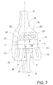
- FIG. 7 shows an enlarged scale and cross section view taken along a front plane of the spacer device according to the first embodiment of the present invention, with the ulnar section arranged according to the second working position;
- FIGS. 8 and 9 respectively illustrate a front view of a spacer device according to a second embodiment of the present invention and a view thereof in longitudinal section taken along a front plane of the device;
- FIG. 10 shows the spacer device according to the first or second embodiment in two work positions, one for bending and one for extending the device itself.
- reference number 1 overall indicates a spacer device according to the present invention for the treatment of infections at the elbow joint, in particular a temporary spacer device to be used during the two-stage treatment of infections, during the time from the explant of a first prosthesis and the implant of a second prosthesis, in order to treat the infection underway at the implant site.
- the spacer device 1 is capable of maintaining the articular space and ensuring the articulation of the elbow up to the implant of the new prosthesis, at the same time treating the infection due to the presence, in the spacer device itself, of suitable drugs or medications, such as one or more antibiotics and by means of the contact of the device with the entire infected area to be treated.
- the spacer device 1 according to the present invention is made of biologically compatible material, additionated and/or additionable with one or more pharmaceutical products, active and/or therapeutic ingredients intended to be released into the tissues of the patient surrounding the device.
- the biologically compatible material of the spacer device 1 according to the present invention is porous, in particular comprises pores that may or may not be interconnected.
- the material for the spacer device 1 according to the present invention can be selected from among the following materials: metals, metallic alloys, organic metals, ceramic, glass, plastic materials.
- the plastic materials may comprise at least one from among: thermoplastic polymers, such as acrylic resins, including all copolymers and acrylic mixtures, polyethylene, polypropylene, etc.
- thermoplastic polymers such as acrylic resins, including all copolymers and acrylic mixtures, polyethylene, polypropylene, etc.
- the biologically compatible material with which the spacer device 1 is obtained comprises a bone cement or polymethyl methacrylate.
- the material of the spacer device according to the present invention can comprise one or more pharmaceutical products, active and/or therapeutic ingredients.
- the pharmaceutical products, active and/or therapeutic ingredients can comprise antibiotics, antiseptics, bacteriostatic agents, bactericides, antimycotics, chemotherapeutic agents, e.g. gentamicin, vancomycin, etcetera, or other active ingredients.
- the material of the spacer device can be added with the drug during production stage, or afterward by the doctor at the time of implant in the patient, e.g. via impregnation. If the spacer device is already provided comprising a pharmaceutical product, an active and/or therapeutic ingredient, it can be subsequently added with further one or more pharmaceutical products, active and/or therapeutic ingredients with the purpose of enlarging the action spectrum or introducing a medication that is highly specific for the identified pathogenic agent. Such further substances may be different from the pharmaceutical products, active and/or therapeutic ingredients already comprised in the spacer device, in order to enlarge the application range thereof.
- the doctor can add vancomycin to oppose the Gram-positive bacteria, or clindamycin for opposing anaerobic bacteria.
- vancomycin to oppose the Gram-positive bacteria, or clindamycin for opposing anaerobic bacteria.
- the solution will be absorbed together with the antibiotic in the mass of the spacer in a few minutes.
- the quantity of absorbed solution can be modified as desired by virtue of the structure of the material.
- Optimal values are comprised between 1 and 60% by weight of absorbed solution. In other words, if the spacer weighs 100 grams, in accordance with its structure, it can absorb from 1 to 60 grams of medicated aqueous solution.
- the spacer device 1 according to a first embodiment of the present invention comprises at least one ulnar section 2 , at least one humeral section 3 delimiting an engagement seat 4 and articulation means 5 , at such engagement seat 4 , intended to achieve the engagement and the articulation between the ulnar section 2 and the humeral section 3 .
- the ulnar section 2 has a stem portion 6 , which is extended along a substantially longitudinal axis x-x between a proximal end 7 and a distal end 8 .
- the humeral section 3 has a stem portion 9 , which extends along a substantially longitudinal axis y-y between a proximal end 10 and a distal end 11 .
- the distal end 11 of the humeral section 3 delimits, as stated above, an engagement seat 4 with the proximal end 7 of the ulnar section 2 .
- the articulation means 5 between the distal end 11 of the humeral section 3 and the proximal end 7 of the ulnar section 2 are, during use, arranged in the engagement seat 4 , along an axis z-z that is orthogonal to said substantially longitudinal axis y-y of the humeral section 3 .
- the humeral section 3 of the spacer device has the stem portion 9 tapered towards its proximal end 10 and has an in use front face 12 , an in use rear face 13 and two right and left in use side faces, right and left, respectively indicated in the figures with the numbers 14 and 15 .
- the distal end 11 of the humeral section 3 is configured to be substantially fork-shaped and comprises two sides 16 , 17 , a right one and a left one during use, each extended from the stem portion 9 at a respective in use side face, 14 or 15 , substantially along the axis y-y.
- the distal end 11 of the humeral section 3 also comprises a front wall 18 for connection between the sides 16 and 17 and connected to the stem 9 at the in use front face 12 .
- Such front wall 18 substantially extends in a cantilevered manner from the in use front face 12 .
- the distal end 11 also comprises a rear wall 18 ′ for connection between the sides 16 and 17 and connected to the stem 9 at the in use rear face 13 roughly coplanar therewith.
- each side 16 or 17 of the distal end 11 of the humeral section 3 has a substantially rounded configuration ( FIGS. 1 and 2 ) with a first substantially rectilinear section 19 or 20 at the connection with the front wall 18 and a second section also substantially rectilinear 19 ′ or 20 ′ at the connection with the in use rear wall 18 ′.
- sides 16 and 17 viewed frontally, have an increasing thickness ( FIGS. 3 to 9 ), moving away from the stem portion 9 .
- the engagement seat 4 also has its own cross section, with respect to the longitudinal axis y-y, increasing moving away from the stem portion 9 .
- the sides 16 and 17 are at a minimum distance 23 near the front wall 18 and at a maximum distance at the most extreme points (with respect to the stem 9 ) of the sides 16 and 17 .
- an optimal distribution is obtained of the forces exerted on the ulnar section 2 and on the humeral section 3 during the use of the spacer device itself, i.e. during the bending-extending movements of the limb in which such spacer device is implanted.
- each side 16 , 17 of the distal end 11 at least one through opening 21 , 22 is obtained, in the example illustrated in the figures only one opening per side.
- the at least one opening on each side 16 or 17 is aligned with at least one other opening in the other side 17 or 16 of the distal end 11 , along a common axis, in the specific case illustrated in the drawings as axis z-z. At such axis, as will be better explained hereinbelow, the articulation means 5 are arranged during use.
- this has its own stem portion 6 tapered towards its distal end 8 and has an in use front face 24 , an in use rear face 25 and two in use side faces, right and left, respectively indicated in the figures with the reference numbers 26 and 27 .
- Each face 26 and 27 at the proximal end 7 of the ulnar section 2 , has a substantially flat and enlarged configuration, with respect to the corresponding distal end 8 of the stem portion. More particularly, at the proximal end 7 , each face 26 and 27 has a substantially round, roughly circular configuration.
- the ulnar section 2 is sized such that the transverse size of its proximal end 7 is smaller than the minimum transverse size (minimum distance 23 ) of the engagement seat 4 of the humeral 5 section 3 , so that it is insertable therein with a certain clearance and, more particularly, it can be moved with a side face 26 or 27 thereof in contact with either side 16 or 17 of the seat itself.
- At the proximal end 7 at least one through opening 28 is obtained, which, during use, is intended to receive the articulation means 5 of 10 the spacer device 1 according to the present invention, as will be better stated hereinbelow.
- Such through opening 28 delimits a gap with substantially hourglass configuration, i.e. with minimum cross section, indicated in FIG. 7 with the letter F, at a longitudinal symmetry plane (not illustrated in the drawings) of 15 the ulnar section 2 passing through the abovementioned axis x-x.
- Such gap has increasing cross section moving away from such longitudinal symmetry plane.
- the articulation means 5 of the spacer device 1 according to the present invention advantageously comprise at least one pin 29 , with cross section corresponding to the minimum gap delimited by the through opening 28 and by 20 the through openings 21 and 22 on the sides 16 and 17 of the distal portion 11 of the humeral section 3 .
- the pin 29 is therefore engageable with the ulnar section 2 , without clearance, only at the minimum cross section of the opening 28 .
- the side wall of the ulnar section 2 delimiting such through opening 28 may or may not touch the pin 29 , 25 in accordance with how the ulnar section 2 is, during use, arranged in the engagement seat 4 .
- the proximal end 7 of the ulnar section 2 inserted in the engagement seat 4 , can slightly move along the axis z-z and complete a slight angular travel around a pivot at the minimum cross section of 30 the opening 28 , indicated with F.
- the proximal end 7 of the ulnar section 2 is engageable in the housing seat 4 of the humeral section 2 with its own longitudinal axis x-x not orthogonal to the axis z-z along which the pin 29 is arranged, between at least two opposed working positions, according to 5 whether the spacer device is intended to be implanted in the right or left upper limb of a patient.
- the proximal end of the ulnar section 2 is situated in the engagement seat 4 adjacent to the side 17 and, therefore, has its own longitudinal axis x-x shifted by ⁇ ° with respect to the axis y-y of the humeral section.
- the spacer device according to the present invention is suitable for being inserted in the upper right limb of a patient.
- the proximal end of the ulnar section 2 is situated in the engagement seat 4 adjacent to the side 16 ( FIGS. 6 and 7 ) 15 and, therefore, has its own longitudinal axis x-x shifted by + ⁇ ° with respect to the axis y-y of the humeral section.
- the spacer device according to the present invention is usable in order to be inserted in the upper left limb of a patient.
- the spacer 20 device is sized such that the proximal portion 7 of the ulnar section 2 , once inserted in the engagement seat 4 of the humeral section 3 , and once the pin 29 is subsequently inserted in the through openings 21 , 22 and 28 of the sides 16 and 17 and of the ulnar section 2 , is rotatable around the pin 29 (as indicated in FIG. 10 ) between a bend position, 25 in which it is situated substantially facing the humeral section 3 and touches the front wall 18 , and an extension position, in which it is situated substantially moved away from the humeral section 3 , aligned therewith.
- the spacer device according to the present invention allows the ulnar section 2 , in the position of maximum extension, to touch the in use rear wall implanted in patients with reduced humeral brachial flexion, the extension of the forearm on the arm and hence of the spacer device is self-limited and in fact the ulnar section 2 never touches the in use rear wall 18 ′ of the humeral section 3 .
- the spacer device comprises means 30 for orienting the ulnar section 2 with respect to the humeral section 3 , housable in the engagement seat 4 .
- Such orientation means 30 are provided for being interposed, in the engagement seat 4 , between the proximal portion 7 of the ulnar section 2 and either side 16 or 17 of the seat 4 .
- the orientation means 30 comprise a bush means, e.g. made of polyethylene, fittable on the articulation means 5 , or any other suitable means capable of maintaining the proximal portion 7 of the ulnar section 2 adjacent to either side 16 or 17 . Included among these are wedge or tilted-wall means.
- the orientation means 30 are advantageously configured as an annular plate 31 and delimit a through opening 32 of size roughly corresponding to that of the gap delimited by the openings 21 and 22 respectively on the sides 16 and 17 of the humeral section 3 .
- Such annular plate 31 can be fit on the pin 29 and has a minimum thickness at its proximal section 33 intended, during use, to be housed in the engagement seat 4 facing the in use front wall 18 of the humeral section 3 .
- the annular plate 31 has a perimeter configuration with rectilinear sections, roughly corresponding to the internal configuration of the seat 4 between the in use front 18 and in use rear 18 ′ walls.
- the thickness of the annular plate instead has its maximum at an opposite or distal section 34 , i.e. during use facing away from the stem 9 of the humeral section.
- the annular plate 31 has its own face directed towards either side 16 or 17 of the humeral section 3 , configured in a manner corresponding to the face of such side directed towards the engagement seat 4 .
- the annular plate 31 has a flange 35 at its opposite or distal section 34 .
- Such flange 35 and the configuration of the annular plate 31 at its proximal section 33 , as well as the configuration of its side faces contribute to ensuring that it remains stopped in position, once it is housed in the seat 4 and fit on the pin 29 .
- the assembly of the spacer device according to the present invention provides for orienting the ulnar section 2 , in the engagement seat 4 , in a manner such that it has its own longitudinal axis x-x shifted by an angle ⁇ °, with respect to the axis y-y of the humeral section 3 .
- the assembly method provides for orienting the ulnar section 2 in a manner such that it has its own longitudinal axis x-x shifted by an angle + ⁇ °, with respect to the axis y-y.
- the orientation means 30 are inserted in the seat, so as to angularly lock the ulnar section 2 by ⁇ 9° with respect to the axis y-y of the humeral section.
- orientation means 30 comprise the annular plate 31 as described above, it will be inserted in the engagement seat 4 in a manner such that its through opening 32 is aligned with the through openings 21 , 22 and 28 along the common axis z-z.
- step of inserting the articulation means 5 in the openings can also occur before the step of orienting the ulnar section 2 towards either one of the sides 16 or 17 of the distal portion 11 of the humeral section, if the orientation means 30 do not require being fit on the pin 29 .
- the spacer device according to the present invention comprises a second embodiment, illustrated in FIGS. 8 and 9 , which differs from the first embodiment since the ulnar section 2 and the orientation means 30 are integrally obtained.
- the orientation means 300 are also configured as an annular plate 301 and delimit a through opening 302 of size roughly corresponding to that of the openings 21 and 22 on the sides 16 and 17 of the humeral section 3 and of the through opening 28 of the ulnar section 2 .
- Such annular plate 301 according to whether the spacer device must be implanted on the right or left limb of a patient, is provided on the face 26 or 27 of the ulnar section itself, so that—depending on the case—the ulnar section is during use adjacent to the side 16 or 17 of the humeral section 3 .
- the orientation means since the orientation means are moved around the pin 29 together with the ulnar section 2 , they have a transverse configuration such to not prevent the rotation of the ulnar section within the engagement seat 4 .
- the orientation means 300 In the specific case illustrated in the figure, the orientation means 300 have a circular crown shaped cross section.
- the gap delimited by the through opening 28 - 302 of the ulnar section has constant cross section.
- the above-described spacer device clearly solves the abovementioned technical problems, since it has a configuration entirely alternative with respect to the spacer devices of conventional type, it comprises a reduced number of components and is also very simple to assemble.
- one such spacer device comprising a stem portion both on the ulnar section 2 and on the humeral section 3 , in turn allows being inserted in respective bone portions of a patient to be treated, thus ensuring the articular mobility and the effective delivery of the antibiotic treatment over a vast area.
- the above-described spacer device 1 is susceptible of numerous modifications and variants within the protective scope of the following claims.
- both the ulnar section 2 and the humeral section 3 comprise a stiffening core, preferably made of metallic material, which contributes to making the spacer device more stress resistant.
- a stiffening core preferably made of metallic material, which contributes to making the spacer device more stress resistant.
- one or more through openings can be made in the stiffening core, which perform the function of reducing the weight thereof while maintaining the core's mechanical characteristics of stress resistance unaltered.
- the stem portion 6 of the ulnar section 2 even if mainly extended along the rectilinear axis x-x, has a medial-distal section not aligned with such axis in order to be better adapted to the anatomy of the patient being treated.
Applications Claiming Priority (4)
| Application Number | Priority Date | Filing Date | Title |
|---|---|---|---|
| ITVR2014A0258 | 2014-10-21 | ||
| ITVR2014A000258 | 2014-10-21 | ||
| ITVR20140258 | 2014-10-21 | ||
| PCT/IB2015/057456 WO2016063155A1 (fr) | 2014-10-21 | 2015-09-29 | Espaceur de coude |
Publications (2)
| Publication Number | Publication Date |
|---|---|
| US20170312086A1 US20170312086A1 (en) | 2017-11-02 |
| US10251753B2 true US10251753B2 (en) | 2019-04-09 |
Family
ID=52101547
Family Applications (1)
| Application Number | Title | Priority Date | Filing Date |
|---|---|---|---|
| US15/519,991 Active 2035-10-07 US10251753B2 (en) | 2014-10-21 | 2015-09-29 | Elbow spacer |
Country Status (7)
| Country | Link |
|---|---|
| US (1) | US10251753B2 (fr) |
| EP (1) | EP3209244B1 (fr) |
| KR (1) | KR102428604B1 (fr) |
| CN (1) | CN107072789B (fr) |
| AU (1) | AU2015334611A1 (fr) |
| ES (1) | ES2748898T3 (fr) |
| WO (1) | WO2016063155A1 (fr) |
Families Citing this family (2)
| Publication number | Priority date | Publication date | Assignee | Title |
|---|---|---|---|---|
| CN110192935A (zh) * | 2019-05-10 | 2019-09-03 | 北京市春立正达医疗器械股份有限公司 | 肘关节假体 |
| IT201900012372A1 (it) | 2019-07-19 | 2021-01-19 | Tecres Spa | Dispositivo spaziatore per il controllo di disturbi o infezioni |
Citations (4)
| Publication number | Priority date | Publication date | Assignee | Title |
|---|---|---|---|---|
| US3708805A (en) | 1969-12-24 | 1973-01-09 | Nat Res Dev | Prosthetic elbow joint |
| US20060052725A1 (en) | 2004-09-03 | 2006-03-09 | Santilli Albert N | Small joint orthopedic implants and their manufacture |
| US20070179609A1 (en) | 2006-01-27 | 2007-08-02 | Medicinelodge, Inc. | Therapeutic agent eluding implant with percutaneous supply |
| US20130345818A1 (en) * | 2012-06-22 | 2013-12-26 | Terry W. Wagner | Elbow prosthesis |
Family Cites Families (18)
| Publication number | Priority date | Publication date | Assignee | Title |
|---|---|---|---|---|
| US2696817A (en) * | 1952-04-30 | 1954-12-14 | Samuel B Prevo | Prosthetic elbow joint |
| US3816854A (en) * | 1973-07-03 | 1974-06-18 | A Schlein | Prosthesis for total arthroplasty of the elbow joint |
| DE4038037B4 (de) * | 1990-11-29 | 2010-06-02 | Waldemar Link Gmbh & Co. Kg | Kniegelenkendoprothese |
| FR2793404B1 (fr) * | 1999-05-14 | 2001-09-14 | Tornier Sa | Prothese de coude |
| WO2002005728A2 (fr) * | 2000-07-18 | 2002-01-24 | Biomet Inc. | Prothese du coude |
| FR2826860B1 (fr) * | 2001-07-09 | 2004-03-05 | Tornier Sa | Ancillaire de pose d'un composant cubital et/ou d'un composant radial de prothese de coude |
| FR2829688B1 (fr) * | 2001-09-14 | 2003-11-21 | Fixano | Prothese totale d'articulation du coude |
| US20040220675A1 (en) * | 2003-04-30 | 2004-11-04 | Lewis Ralph Harrison | Total elbow replacement for dogs |
| CN2659380Y (zh) * | 2003-11-28 | 2004-12-01 | 曲彦隆 | 自锁全肘关节置换假体 |
| US7449028B2 (en) * | 2004-10-29 | 2008-11-11 | Depuy Products, Inc. | Modular total elbow prosthesis, humeral component and associated kit |
| US20060100713A1 (en) * | 2004-10-29 | 2006-05-11 | Ball Robert J | Mobile bearing total elbow prosthesis, ulnar component, and associated kit |
| JP2007075129A (ja) * | 2005-09-09 | 2007-03-29 | Okayama Univ | 人工肘関節 |
| EP2037844B1 (fr) * | 2006-06-28 | 2011-12-28 | Mayo Foundation for Medical Education and Research | Système prothétique de remplacement du coude |
| US8613774B2 (en) * | 2009-11-16 | 2013-12-24 | New York Society For The Ruptured And Crippled Maintaining The Hospital For Special Surgery | Elbow replacement apparatus and methods |
| US8647388B2 (en) * | 2010-08-27 | 2014-02-11 | Bluefish Orthopedics, Llc | Elbow prosthesis and method for use |
| CN201861799U (zh) * | 2010-10-26 | 2011-06-15 | 深圳职业技术学院 | 一种肱骨远端假体 |
| CN101984939A (zh) * | 2010-12-16 | 2011-03-16 | 西安福安创意咨询有限责任公司 | 钽涂层人工肘关节假体的设计方法 |
| CN201879868U (zh) * | 2010-12-16 | 2011-06-29 | 段永宏 | 钽涂层人工肘关节假体 |
-
2015
- 2015-09-29 CN CN201580056415.3A patent/CN107072789B/zh active Active
- 2015-09-29 KR KR1020177012234A patent/KR102428604B1/ko active IP Right Grant
- 2015-09-29 WO PCT/IB2015/057456 patent/WO2016063155A1/fr active Application Filing
- 2015-09-29 AU AU2015334611A patent/AU2015334611A1/en not_active Abandoned
- 2015-09-29 EP EP15797404.9A patent/EP3209244B1/fr active Active
- 2015-09-29 US US15/519,991 patent/US10251753B2/en active Active
- 2015-09-29 ES ES15797404T patent/ES2748898T3/es active Active
Patent Citations (4)
| Publication number | Priority date | Publication date | Assignee | Title |
|---|---|---|---|---|
| US3708805A (en) | 1969-12-24 | 1973-01-09 | Nat Res Dev | Prosthetic elbow joint |
| US20060052725A1 (en) | 2004-09-03 | 2006-03-09 | Santilli Albert N | Small joint orthopedic implants and their manufacture |
| US20070179609A1 (en) | 2006-01-27 | 2007-08-02 | Medicinelodge, Inc. | Therapeutic agent eluding implant with percutaneous supply |
| US20130345818A1 (en) * | 2012-06-22 | 2013-12-26 | Terry W. Wagner | Elbow prosthesis |
Also Published As
| Publication number | Publication date |
|---|---|
| ES2748898T3 (es) | 2020-03-18 |
| CN107072789A (zh) | 2017-08-18 |
| AU2015334611A1 (en) | 2017-05-25 |
| WO2016063155A1 (fr) | 2016-04-28 |
| KR102428604B1 (ko) | 2022-08-02 |
| EP3209244A1 (fr) | 2017-08-30 |
| US20170312086A1 (en) | 2017-11-02 |
| CN107072789B (zh) | 2019-03-08 |
| EP3209244B1 (fr) | 2019-08-21 |
| KR20170072239A (ko) | 2017-06-26 |
Similar Documents
| Publication | Publication Date | Title |
|---|---|---|
| KR101504390B1 (ko) | 관절-보철물 감염 치료용 모듈형 스페이서 | |
| JP7092326B2 (ja) | 全関節置換術感染予防デバイスおよび方法 | |
| CN107072788B (zh) | 用于膝关节的受约束的间隔件装置 | |
| IL139230A0 (en) | Preparations for the application of anti-inflammatory, especially antiseptic agents and/or agents promoting the healing of wounds to the upper respiratory tract and/or the ear | |
| KR102461337B1 (ko) | 무릎 관절을 위한 개선된 조절가능한 모듈형 스페이서 장치 | |
| US10251753B2 (en) | Elbow spacer | |
| US20140094752A1 (en) | Guide Device for Intraocular Injection | |
| Farnsworth et al. | The effect of implanting gentamicin‐impregnated polymethylmethacrylate beads in the tarsocrural joint of the horse | |
| WO2023216509A1 (fr) | Prothèse implantaire | |
| US10299932B2 (en) | Elbow prosthesis | |
| KR102497061B1 (ko) | 어깨 관절의 감염을 치료하기 위한 스페이서 장치 | |
| Akdoğan et al. | Comparison of the Aquacel Ag surgical dressing vs standard dressing in the treatment of the wound site infection and patient comfort in total knee arthroplasty. | |
| RU2725272C1 (ru) | Способ лечения перипротезной инфекции при эндопротезировании коленного сустава | |
| NL2023208B1 (en) | Sleeve element to be placed on a neck of a prosthetic hip or shoulder implant. | |
| BR0104586A (pt) | Método para tratamento de neurodegeneração | |
| NZ703464A (en) | Controlled release formulations comprising uncoated discrete unit(s) and an extended release matrix | |
| Cooper et al. | The use of honey in healing a recalcitrant wound following surgical treatment of hidradenitis suppurativa | |
| SE9901257D0 (sv) | Behandling av smärta efter ledoperation | |
| Shaker et al. | PHARMACOKINETIC OF GOLD NANOPARTICLE-VANCOMYCIN DELIVERY IN OSTEOMYELITIS INDUCED BY MRSA IN RABBITS. | |
| TWM465151U (zh) | 多孔式人工膝關節 | |
| US10143557B1 (en) | Total elbow arthroplasty apparatus and method | |
| AU2002331530A1 (en) | Thyroid therapeutic agents containing partial glycerides and dextrin | |
| Varfolomeev | New spacers for the treatment of peri-implant infection |
Legal Events
| Date | Code | Title | Description |
|---|---|---|---|
| AS | Assignment |
Owner name: TECRES S.P.A., ITALY Free format text: ASSIGNMENT OF ASSIGNORS INTEREST;ASSIGNORS:SOFFIATTI, RENZO;FACCIOLI, GIOVANNI;REEL/FRAME:042355/0534 Effective date: 20170505 |
|
| STCF | Information on status: patent grant |
Free format text: PATENTED CASE |
|
| MAFP | Maintenance fee payment |
Free format text: PAYMENT OF MAINTENANCE FEE, 4TH YR, SMALL ENTITY (ORIGINAL EVENT CODE: M2551); ENTITY STATUS OF PATENT OWNER: SMALL ENTITY Year of fee payment: 4 |