EP3209244B1 - Espaceur de coude - Google Patents
Espaceur de coude Download PDFInfo
- Publication number
- EP3209244B1 EP3209244B1 EP15797404.9A EP15797404A EP3209244B1 EP 3209244 B1 EP3209244 B1 EP 3209244B1 EP 15797404 A EP15797404 A EP 15797404A EP 3209244 B1 EP3209244 B1 EP 3209244B1
- Authority
- EP
- European Patent Office
- Prior art keywords
- section
- spacer device
- ulnar
- humeral
- axis
- Prior art date
- Legal status (The legal status is an assumption and is not a legal conclusion. Google has not performed a legal analysis and makes no representation as to the accuracy of the status listed.)
- Active
Links
- 125000006850 spacer group Chemical group 0.000 title claims description 95
- 208000015181 infectious disease Diseases 0.000 claims description 22
- 210000002310 elbow joint Anatomy 0.000 claims description 14
- 210000003414 extremity Anatomy 0.000 claims description 12
- 239000007943 implant Substances 0.000 claims description 10
- 230000001419 dependent effect Effects 0.000 claims description 6
- 238000000034 method Methods 0.000 claims description 5
- 210000001364 upper extremity Anatomy 0.000 claims description 2
- 239000000463 material Substances 0.000 description 10
- 239000003814 drug Substances 0.000 description 7
- 229940079593 drug Drugs 0.000 description 6
- 239000004615 ingredient Substances 0.000 description 6
- 239000000825 pharmaceutical preparation Substances 0.000 description 6
- 229940127557 pharmaceutical product Drugs 0.000 description 6
- 230000001225 therapeutic effect Effects 0.000 description 6
- 230000003115 biocidal effect Effects 0.000 description 4
- -1 polyethylene Polymers 0.000 description 4
- 210000001519 tissue Anatomy 0.000 description 4
- 230000002829 reductive effect Effects 0.000 description 3
- 239000000243 solution Substances 0.000 description 3
- CEAZRRDELHUEMR-URQXQFDESA-N Gentamicin Chemical compound O1[C@H](C(C)NC)CC[C@@H](N)[C@H]1O[C@H]1[C@H](O)[C@@H](O[C@@H]2[C@@H]([C@@H](NC)[C@@](C)(O)CO2)O)[C@H](N)C[C@@H]1N CEAZRRDELHUEMR-URQXQFDESA-N 0.000 description 2
- 229930182566 Gentamicin Natural products 0.000 description 2
- 239000004698 Polyethylene Substances 0.000 description 2
- 108010059993 Vancomycin Proteins 0.000 description 2
- 239000004480 active ingredient Substances 0.000 description 2
- 239000003242 anti bacterial agent Substances 0.000 description 2
- 229940088710 antibiotic agent Drugs 0.000 description 2
- 238000005452 bending Methods 0.000 description 2
- 210000000245 forearm Anatomy 0.000 description 2
- 229960002518 gentamicin Drugs 0.000 description 2
- 239000002184 metal Substances 0.000 description 2
- 229910052751 metal Inorganic materials 0.000 description 2
- 150000002739 metals Chemical class 0.000 description 2
- 239000004033 plastic Substances 0.000 description 2
- 229920003023 plastic Polymers 0.000 description 2
- 229920000573 polyethylene Polymers 0.000 description 2
- 229960003165 vancomycin Drugs 0.000 description 2
- MYPYJXKWCTUITO-LYRMYLQWSA-N vancomycin Chemical compound O([C@@H]1[C@@H](O)[C@H](O)[C@@H](CO)O[C@H]1OC1=C2C=C3C=C1OC1=CC=C(C=C1Cl)[C@@H](O)[C@H](C(N[C@@H](CC(N)=O)C(=O)N[C@H]3C(=O)N[C@H]1C(=O)N[C@H](C(N[C@@H](C3=CC(O)=CC(O)=C3C=3C(O)=CC=C1C=3)C(O)=O)=O)[C@H](O)C1=CC=C(C(=C1)Cl)O2)=O)NC(=O)[C@@H](CC(C)C)NC)[C@H]1C[C@](C)(N)[C@H](O)[C@H](C)O1 MYPYJXKWCTUITO-LYRMYLQWSA-N 0.000 description 2
- MYPYJXKWCTUITO-UHFFFAOYSA-N vancomycin Natural products O1C(C(=C2)Cl)=CC=C2C(O)C(C(NC(C2=CC(O)=CC(O)=C2C=2C(O)=CC=C3C=2)C(O)=O)=O)NC(=O)C3NC(=O)C2NC(=O)C(CC(N)=O)NC(=O)C(NC(=O)C(CC(C)C)NC)C(O)C(C=C3Cl)=CC=C3OC3=CC2=CC1=C3OC1OC(CO)C(O)C(O)C1OC1CC(C)(N)C(O)C(C)O1 MYPYJXKWCTUITO-UHFFFAOYSA-N 0.000 description 2
- 239000004925 Acrylic resin Substances 0.000 description 1
- 229920000178 Acrylic resin Polymers 0.000 description 1
- 241000192125 Firmicutes Species 0.000 description 1
- 239000004743 Polypropylene Substances 0.000 description 1
- NIXOWILDQLNWCW-UHFFFAOYSA-N acrylic acid group Chemical group C(C=C)(=O)O NIXOWILDQLNWCW-UHFFFAOYSA-N 0.000 description 1
- 238000001720 action spectrum Methods 0.000 description 1
- 238000007792 addition Methods 0.000 description 1
- 210000003484 anatomy Anatomy 0.000 description 1
- 230000000844 anti-bacterial effect Effects 0.000 description 1
- 230000001857 anti-mycotic effect Effects 0.000 description 1
- 230000002421 anti-septic effect Effects 0.000 description 1
- 239000012984 antibiotic solution Substances 0.000 description 1
- 239000002543 antimycotic Substances 0.000 description 1
- 239000002246 antineoplastic agent Substances 0.000 description 1
- 229940064004 antiseptic throat preparations Drugs 0.000 description 1
- 239000007864 aqueous solution Substances 0.000 description 1
- 239000003899 bactericide agent Substances 0.000 description 1
- 239000000022 bacteriostatic agent Substances 0.000 description 1
- 210000000988 bone and bone Anatomy 0.000 description 1
- 239000002639 bone cement Substances 0.000 description 1
- 239000002775 capsule Substances 0.000 description 1
- 239000000919 ceramic Substances 0.000 description 1
- 239000003795 chemical substances by application Substances 0.000 description 1
- 229960002227 clindamycin Drugs 0.000 description 1
- KDLRVYVGXIQJDK-AWPVFWJPSA-N clindamycin Chemical compound CN1C[C@H](CCC)C[C@H]1C(=O)N[C@H]([C@H](C)Cl)[C@@H]1[C@H](O)[C@H](O)[C@@H](O)[C@@H](SC)O1 KDLRVYVGXIQJDK-AWPVFWJPSA-N 0.000 description 1
- 230000002860 competitive effect Effects 0.000 description 1
- 229920001577 copolymer Polymers 0.000 description 1
- 229940127089 cytotoxic agent Drugs 0.000 description 1
- 238000009826 distribution Methods 0.000 description 1
- 239000011521 glass Substances 0.000 description 1
- 238000005470 impregnation Methods 0.000 description 1
- 238000011065 in-situ storage Methods 0.000 description 1
- 230000003902 lesion Effects 0.000 description 1
- 230000000670 limiting effect Effects 0.000 description 1
- 238000004519 manufacturing process Methods 0.000 description 1
- 238000002483 medication Methods 0.000 description 1
- 229910001092 metal group alloy Inorganic materials 0.000 description 1
- 239000007769 metal material Substances 0.000 description 1
- 239000000203 mixture Substances 0.000 description 1
- 238000012986 modification Methods 0.000 description 1
- 230000004048 modification Effects 0.000 description 1
- 230000036961 partial effect Effects 0.000 description 1
- 230000001717 pathogenic effect Effects 0.000 description 1
- 229920003229 poly(methyl methacrylate) Polymers 0.000 description 1
- 239000004926 polymethyl methacrylate Substances 0.000 description 1
- 229920001155 polypropylene Polymers 0.000 description 1
- 239000011148 porous material Substances 0.000 description 1
- 230000001681 protective effect Effects 0.000 description 1
- 239000000126 substance Substances 0.000 description 1
- 229940124597 therapeutic agent Drugs 0.000 description 1
- 229920001169 thermoplastic Polymers 0.000 description 1
- 241001148471 unidentified anaerobic bacterium Species 0.000 description 1
Images


Classifications
-
- A—HUMAN NECESSITIES
- A61—MEDICAL OR VETERINARY SCIENCE; HYGIENE
- A61F—FILTERS IMPLANTABLE INTO BLOOD VESSELS; PROSTHESES; DEVICES PROVIDING PATENCY TO, OR PREVENTING COLLAPSING OF, TUBULAR STRUCTURES OF THE BODY, e.g. STENTS; ORTHOPAEDIC, NURSING OR CONTRACEPTIVE DEVICES; FOMENTATION; TREATMENT OR PROTECTION OF EYES OR EARS; BANDAGES, DRESSINGS OR ABSORBENT PADS; FIRST-AID KITS
- A61F2/00—Filters implantable into blood vessels; Prostheses, i.e. artificial substitutes or replacements for parts of the body; Appliances for connecting them with the body; Devices providing patency to, or preventing collapsing of, tubular structures of the body, e.g. stents
- A61F2/02—Prostheses implantable into the body
- A61F2/30—Joints
- A61F2/38—Joints for elbows or knees
- A61F2/3804—Joints for elbows or knees for elbows
-
- A—HUMAN NECESSITIES
- A61—MEDICAL OR VETERINARY SCIENCE; HYGIENE
- A61F—FILTERS IMPLANTABLE INTO BLOOD VESSELS; PROSTHESES; DEVICES PROVIDING PATENCY TO, OR PREVENTING COLLAPSING OF, TUBULAR STRUCTURES OF THE BODY, e.g. STENTS; ORTHOPAEDIC, NURSING OR CONTRACEPTIVE DEVICES; FOMENTATION; TREATMENT OR PROTECTION OF EYES OR EARS; BANDAGES, DRESSINGS OR ABSORBENT PADS; FIRST-AID KITS
- A61F2/00—Filters implantable into blood vessels; Prostheses, i.e. artificial substitutes or replacements for parts of the body; Appliances for connecting them with the body; Devices providing patency to, or preventing collapsing of, tubular structures of the body, e.g. stents
- A61F2/02—Prostheses implantable into the body
- A61F2/30—Joints
- A61F2/46—Special tools or methods for implanting or extracting artificial joints, accessories, bone grafts or substitutes, or particular adaptations therefor
- A61F2/4603—Special tools or methods for implanting or extracting artificial joints, accessories, bone grafts or substitutes, or particular adaptations therefor for insertion or extraction of endoprosthetic joints or of accessories thereof
- A61F2/4605—Special tools or methods for implanting or extracting artificial joints, accessories, bone grafts or substitutes, or particular adaptations therefor for insertion or extraction of endoprosthetic joints or of accessories thereof of elbows
-
- A—HUMAN NECESSITIES
- A61—MEDICAL OR VETERINARY SCIENCE; HYGIENE
- A61F—FILTERS IMPLANTABLE INTO BLOOD VESSELS; PROSTHESES; DEVICES PROVIDING PATENCY TO, OR PREVENTING COLLAPSING OF, TUBULAR STRUCTURES OF THE BODY, e.g. STENTS; ORTHOPAEDIC, NURSING OR CONTRACEPTIVE DEVICES; FOMENTATION; TREATMENT OR PROTECTION OF EYES OR EARS; BANDAGES, DRESSINGS OR ABSORBENT PADS; FIRST-AID KITS
- A61F2/00—Filters implantable into blood vessels; Prostheses, i.e. artificial substitutes or replacements for parts of the body; Appliances for connecting them with the body; Devices providing patency to, or preventing collapsing of, tubular structures of the body, e.g. stents
- A61F2/02—Prostheses implantable into the body
- A61F2/30—Joints
- A61F2002/30001—Additional features of subject-matter classified in A61F2/28, A61F2/30 and subgroups thereof
- A61F2002/30621—Features concerning the anatomical functioning or articulation of the prosthetic joint
- A61F2002/30624—Hinged joint, e.g. with transverse axle restricting the movement
-
- A—HUMAN NECESSITIES
- A61—MEDICAL OR VETERINARY SCIENCE; HYGIENE
- A61F—FILTERS IMPLANTABLE INTO BLOOD VESSELS; PROSTHESES; DEVICES PROVIDING PATENCY TO, OR PREVENTING COLLAPSING OF, TUBULAR STRUCTURES OF THE BODY, e.g. STENTS; ORTHOPAEDIC, NURSING OR CONTRACEPTIVE DEVICES; FOMENTATION; TREATMENT OR PROTECTION OF EYES OR EARS; BANDAGES, DRESSINGS OR ABSORBENT PADS; FIRST-AID KITS
- A61F2/00—Filters implantable into blood vessels; Prostheses, i.e. artificial substitutes or replacements for parts of the body; Appliances for connecting them with the body; Devices providing patency to, or preventing collapsing of, tubular structures of the body, e.g. stents
- A61F2/02—Prostheses implantable into the body
- A61F2/30—Joints
- A61F2002/30001—Additional features of subject-matter classified in A61F2/28, A61F2/30 and subgroups thereof
- A61F2002/30667—Features concerning an interaction with the environment or a particular use of the prosthesis
- A61F2002/30672—Features concerning an interaction with the environment or a particular use of the prosthesis temporary
-
- A—HUMAN NECESSITIES
- A61—MEDICAL OR VETERINARY SCIENCE; HYGIENE
- A61F—FILTERS IMPLANTABLE INTO BLOOD VESSELS; PROSTHESES; DEVICES PROVIDING PATENCY TO, OR PREVENTING COLLAPSING OF, TUBULAR STRUCTURES OF THE BODY, e.g. STENTS; ORTHOPAEDIC, NURSING OR CONTRACEPTIVE DEVICES; FOMENTATION; TREATMENT OR PROTECTION OF EYES OR EARS; BANDAGES, DRESSINGS OR ABSORBENT PADS; FIRST-AID KITS
- A61F2/00—Filters implantable into blood vessels; Prostheses, i.e. artificial substitutes or replacements for parts of the body; Appliances for connecting them with the body; Devices providing patency to, or preventing collapsing of, tubular structures of the body, e.g. stents
- A61F2/02—Prostheses implantable into the body
- A61F2/30—Joints
- A61F2002/30001—Additional features of subject-matter classified in A61F2/28, A61F2/30 and subgroups thereof
- A61F2002/30667—Features concerning an interaction with the environment or a particular use of the prosthesis
- A61F2002/30677—Means for introducing or releasing pharmaceutical products, e.g. antibiotics, into the body
-
- A—HUMAN NECESSITIES
- A61—MEDICAL OR VETERINARY SCIENCE; HYGIENE
- A61F—FILTERS IMPLANTABLE INTO BLOOD VESSELS; PROSTHESES; DEVICES PROVIDING PATENCY TO, OR PREVENTING COLLAPSING OF, TUBULAR STRUCTURES OF THE BODY, e.g. STENTS; ORTHOPAEDIC, NURSING OR CONTRACEPTIVE DEVICES; FOMENTATION; TREATMENT OR PROTECTION OF EYES OR EARS; BANDAGES, DRESSINGS OR ABSORBENT PADS; FIRST-AID KITS
- A61F2/00—Filters implantable into blood vessels; Prostheses, i.e. artificial substitutes or replacements for parts of the body; Appliances for connecting them with the body; Devices providing patency to, or preventing collapsing of, tubular structures of the body, e.g. stents
- A61F2/02—Prostheses implantable into the body
- A61F2/30—Joints
- A61F2/30767—Special external or bone-contacting surface, e.g. coating for improving bone ingrowth
- A61F2002/3092—Special external or bone-contacting surface, e.g. coating for improving bone ingrowth having an open-celled or open-pored structure
-
- A—HUMAN NECESSITIES
- A61—MEDICAL OR VETERINARY SCIENCE; HYGIENE
- A61F—FILTERS IMPLANTABLE INTO BLOOD VESSELS; PROSTHESES; DEVICES PROVIDING PATENCY TO, OR PREVENTING COLLAPSING OF, TUBULAR STRUCTURES OF THE BODY, e.g. STENTS; ORTHOPAEDIC, NURSING OR CONTRACEPTIVE DEVICES; FOMENTATION; TREATMENT OR PROTECTION OF EYES OR EARS; BANDAGES, DRESSINGS OR ABSORBENT PADS; FIRST-AID KITS
- A61F2/00—Filters implantable into blood vessels; Prostheses, i.e. artificial substitutes or replacements for parts of the body; Appliances for connecting them with the body; Devices providing patency to, or preventing collapsing of, tubular structures of the body, e.g. stents
- A61F2/02—Prostheses implantable into the body
- A61F2/30—Joints
- A61F2/38—Joints for elbows or knees
- A61F2/3804—Joints for elbows or knees for elbows
- A61F2002/3813—Joints for elbows or knees for elbows for ulno-humeral joints
-
- A—HUMAN NECESSITIES
- A61—MEDICAL OR VETERINARY SCIENCE; HYGIENE
- A61F—FILTERS IMPLANTABLE INTO BLOOD VESSELS; PROSTHESES; DEVICES PROVIDING PATENCY TO, OR PREVENTING COLLAPSING OF, TUBULAR STRUCTURES OF THE BODY, e.g. STENTS; ORTHOPAEDIC, NURSING OR CONTRACEPTIVE DEVICES; FOMENTATION; TREATMENT OR PROTECTION OF EYES OR EARS; BANDAGES, DRESSINGS OR ABSORBENT PADS; FIRST-AID KITS
- A61F2/00—Filters implantable into blood vessels; Prostheses, i.e. artificial substitutes or replacements for parts of the body; Appliances for connecting them with the body; Devices providing patency to, or preventing collapsing of, tubular structures of the body, e.g. stents
- A61F2/02—Prostheses implantable into the body
- A61F2/30—Joints
- A61F2/38—Joints for elbows or knees
- A61F2/3804—Joints for elbows or knees for elbows
- A61F2002/3822—Humeral components
-
- A—HUMAN NECESSITIES
- A61—MEDICAL OR VETERINARY SCIENCE; HYGIENE
- A61F—FILTERS IMPLANTABLE INTO BLOOD VESSELS; PROSTHESES; DEVICES PROVIDING PATENCY TO, OR PREVENTING COLLAPSING OF, TUBULAR STRUCTURES OF THE BODY, e.g. STENTS; ORTHOPAEDIC, NURSING OR CONTRACEPTIVE DEVICES; FOMENTATION; TREATMENT OR PROTECTION OF EYES OR EARS; BANDAGES, DRESSINGS OR ABSORBENT PADS; FIRST-AID KITS
- A61F2/00—Filters implantable into blood vessels; Prostheses, i.e. artificial substitutes or replacements for parts of the body; Appliances for connecting them with the body; Devices providing patency to, or preventing collapsing of, tubular structures of the body, e.g. stents
- A61F2/02—Prostheses implantable into the body
- A61F2/30—Joints
- A61F2/38—Joints for elbows or knees
- A61F2/3804—Joints for elbows or knees for elbows
- A61F2002/3831—Ulnar components
-
- A—HUMAN NECESSITIES
- A61—MEDICAL OR VETERINARY SCIENCE; HYGIENE
- A61F—FILTERS IMPLANTABLE INTO BLOOD VESSELS; PROSTHESES; DEVICES PROVIDING PATENCY TO, OR PREVENTING COLLAPSING OF, TUBULAR STRUCTURES OF THE BODY, e.g. STENTS; ORTHOPAEDIC, NURSING OR CONTRACEPTIVE DEVICES; FOMENTATION; TREATMENT OR PROTECTION OF EYES OR EARS; BANDAGES, DRESSINGS OR ABSORBENT PADS; FIRST-AID KITS
- A61F2/00—Filters implantable into blood vessels; Prostheses, i.e. artificial substitutes or replacements for parts of the body; Appliances for connecting them with the body; Devices providing patency to, or preventing collapsing of, tubular structures of the body, e.g. stents
- A61F2/02—Prostheses implantable into the body
- A61F2/30—Joints
- A61F2/46—Special tools or methods for implanting or extracting artificial joints, accessories, bone grafts or substitutes, or particular adaptations therefor
- A61F2/4603—Special tools or methods for implanting or extracting artificial joints, accessories, bone grafts or substitutes, or particular adaptations therefor for insertion or extraction of endoprosthetic joints or of accessories thereof
- A61F2002/4615—Special tools or methods for implanting or extracting artificial joints, accessories, bone grafts or substitutes, or particular adaptations therefor for insertion or extraction of endoprosthetic joints or of accessories thereof of spacers
-
- A—HUMAN NECESSITIES
- A61—MEDICAL OR VETERINARY SCIENCE; HYGIENE
- A61F—FILTERS IMPLANTABLE INTO BLOOD VESSELS; PROSTHESES; DEVICES PROVIDING PATENCY TO, OR PREVENTING COLLAPSING OF, TUBULAR STRUCTURES OF THE BODY, e.g. STENTS; ORTHOPAEDIC, NURSING OR CONTRACEPTIVE DEVICES; FOMENTATION; TREATMENT OR PROTECTION OF EYES OR EARS; BANDAGES, DRESSINGS OR ABSORBENT PADS; FIRST-AID KITS
- A61F2310/00—Prostheses classified in A61F2/28 or A61F2/30 - A61F2/44 being constructed from or coated with a particular material
- A61F2310/00005—The prosthesis being constructed from a particular material
- A61F2310/00353—Bone cement, e.g. polymethylmethacrylate or PMMA
Definitions
- the present invention regards a spacer device for the elbow joint, particularly employable in the treatment of infections according to the so-called "two-stage" treatment.
- the elbow joint although it is often considered to be a single articulation, comprises three separate articulations, associated with a single capsule. These are the humeroradial articulation, the humeroulnar articulation, which allows the bending and extending movements of the forearm on the arm, and the proximal radioulnar articulation, which allows the prono-supination of the hand.
- the present invention regards a spacer device that affects the humeroulnar joint.
- US2007179609A1 discloses a prosthesis with a therapeutic agent delivery system including one or more channels.
- the channels may receive medication from an external pump via a percutaneous catheter and deliver such medication to one or more surfaces of the prosthesis in order to treat proximate tissues.
- US3708805A discloses a prosthesis for an elbow joint comprising a humeral member, an ulnar member and a connecting piece to connect the humeral and ulnar members and allow hinging movement of the one relative to the other.
- the explant of the prosthesis is therefore necessary for treating the infection, and once the infected tissues have healed, it is necessary to implant a new permanent prosthesis.
- Such method for treating the infection is usually defined two-stage treatment, since it provides for a first step for removing the prosthesis and a second step for implanting a new prosthesis, once the infection has been eliminated.
- the treatment of the infection requires the use of a spacer device which, in addition to maintaining the articular portions suitably spaced from each other during treatment, comes into contact or is interfaced with the space left free by the removed prosthesis and gradually releases antibiotic or another active ingredient suitable for treating the specific infection, with consequent treatment of the infection itself.
- One such spacer device also allows a patient to maintain at least a partial mobility of the treated limb.
- the spacer devices currently on the market are negatively affected by the drawback that, even if they allow suitably maintaining the articular portions spaced during the treatment stage, they do not allow any mobility of the limb.
- the technical task of the present invention is to improve the state of the art in the field of spacer devices for the elbow joint.
- one object of the present invention is to provide a spacer device for the treatment of infections at the elbow joint which has an alternative configuration with respect to that of the conventional spacer devices.
- Another object of the present invention is to provide a spacer device for the treatment of infections at the elbow joint which allows the articular mobility once this has been implanted in situ.
- Still another object of the present invention is to provide a spacer device for the treatment of infections at the elbow joint which is composed of a reduced number of components.
- a further object of the present invention is to provide a spacer device for the treatment of infections at the elbow joint which can be obtained at competitive costs.
- Not least object of the present invention is to provide a spacer device for the treatment of infections at the elbow joint which is easy to assemble.
- a temporary spacer device is provided for the treatment of infections at the elbow joint according to claim 1.
- a method for assembling a temporary spacer device for the treatment of infections at the elbow joint according to the enclosed claims 29 and 30.
- reference number 1 overall indicates a temporary spacer device according to the present invention for the treatment of infections at the elbow joint, which is a temporary spacer device to be used in particular during the two-stage treatment of infections, during the time from the explant of a first prosthesis and the implant of a second prosthesis, in order to treat the infection underway at the implant site.
- the spacer device 1 is capable of maintaining the articular space and ensuring the articulation of the elbow up to the implant of the new prosthesis, at the same time treating the infection due to the presence, in the spacer device itself, of suitable drugs or medications, such as one or more antibiotics and by means of the contact of the device with the entire infected area to be treated.
- the spacer device 1 according to the present invention is made of biologically compatible material, additionated and/or additionable with one or more pharmaceutical products, active and/or therapeutic ingredients intended to be released into the tissues of the patient surrounding the device.
- the biologically compatible material of the spacer device 1 according to the present invention is porous, in particular comprises pores that may or may not be interconnected.
- the material for the spacer device 1 according to the present invention can be selected from among the following materials: metals, metallic alloys, organic metals, ceramic, glass, plastic materials.
- the plastic materials may comprise at least one from among: thermoplastic polymers, such as acrylic resins, including all copolymers and acrylic mixtures, polyethylene, polypropylene, etc.
- thermoplastic polymers such as acrylic resins, including all copolymers and acrylic mixtures, polyethylene, polypropylene, etc.
- the biologically compatible material with which the spacer device 1 is obtained comprises a bone cement or polymethyl methacrylate.
- the material of the spacer device according to the present invention can comprise one or more pharmaceutical products, active and/or therapeutic ingredients.
- the pharmaceutical products, active and/or therapeutic ingredients can comprise antibiotics, antiseptics, bacteriostatic agents, bactericides, antimycotics, chemotherapeutic agents, e.g. gentamicin, vancomycin, etcetera, or other active ingredients.
- the material of the spacer device can be added with the drug during production stage, or afterward by the doctor at the time of implant in the patient, e.g. via impregnation. If the spacer device is already provided comprising a pharmaceutical product, an active and/or therapeutic ingredient, it can be subsequently added with further one or more pharmaceutical products, active and/or therapeutic ingredients with the purpose of enlarging the action spectrum or introducing a medication that is highly specific for the identified pathogenic agent. Such further substances may be different from the pharmaceutical products, active and/or therapeutic ingredients already comprised in the spacer device, in order to enlarge the application range thereof.
- the doctor can add vancomycin to oppose the Gram-positive bacteria, or clindamycin for opposing anaerobic bacteria.
- vancomycin to oppose the Gram-positive bacteria, or clindamycin for opposing anaerobic bacteria.
- the solution will be absorbed together with the antibiotic in the mass of the spacer in a few minutes.
- the quantity of absorbed solution can be modified as desired by virtue of the structure of the material.
- Optimal values are comprised between 1 and 60% by weight of absorbed solution. In other words, if the spacer weighs 100 grams, in accordance with its structure, it can absorb from 1 to 60 grams of medicated aqueous solution.
- the spacer device 1 according to a first embodiment of the present invention comprises at least one ulnar section 2, at least one humeral section 3 delimiting an engagement seat 4 and articulation means 5, at such engagement seat 4, intended to achieve the engagement and the articulation between the ulnar section 2 and the humeral section 3.
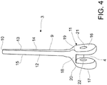
- the ulnar section 2 has a stem portion 6, which is extended along a substantially longitudinal axis x-x between a proximal end 7 and a distal end 8.
- the humeral section 3 has a stem portion 9, which extends along a substantially longitudinal axis y-y between a proximal end 10 and a distal end 11.
- the distal end 11 of the humeral section 3 delimits, as stated above, an engagement seat 4 with the proximal end 7 of the ulnar section 2.
- the articulation means 5 between the distal end 11 of the humeral section 3 and the proximal end 7 of the ulnar section 2, as will be better stated hereinbelow, are, during use, arranged in the engagement seat 4, along an axis z-z that is orthogonal to said substantially longitudinal axis y-y of the humeral section 3.
- the humeral section 3 of the spacer device according to the present invention has the stem portion 9 tapered towards its proximal end 10 and has an in use front face 12, an in use rear face 13 and two right and left in use side faces, right and left, respectively indicated in the figures with the numbers 14 and 15.
- the distal end 11 of the humeral section 3 is configured to be substantially fork-shaped and comprises two sides 16, 17, a right one and a left one during use, each extended from the stem portion 9 at a respective in use side face, 14 or 15, substantially along the axis y-y.
- the distal end 11 of the humeral section 3 also comprises a front wall 18 for connection between the sides 16 and 17 and connected to the stem 9 at the in use front face 12.
- Such front wall 18 substantially extends in a cantilevered manner from the in use front face 12.
- the distal end 11 also comprises a rear wall 18' for connection between the sides 16 and 17 and connected to the stem 9 at the in use rear face 13 roughly coplanar therewith.
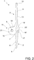
- each side 16 or 17 of the distal end 11 of the humeral section 3, viewed laterally, has a substantially rounded configuration ( figures 1 and 2 ) with a first substantially rectilinear section 19 or 20 at the connection with the front wall 18 and a second section also substantially rectilinear 19' or 20' at the connection with the in use rear wall 18'.
- sides 16 and 17, viewed frontally, have an increasing thickness ( Figures 3 to 9 ), moving away from the stem portion 9.
- the engagement seat 4 also has its own cross section, with respect to the longitudinal axis y-y, increasing moving away from the stem portion 9.
- the sides 16 and 17 are at a minimum distance 23 near the front wall 18 and at a maximum distance at the most extreme points (with respect to the stem 9) of the sides 16 and 17.
- an optimal distribution is obtained of the forces exerted on the ulnar section 2 and on the humeral section 3 during the use of the spacer device itself, i.e. during the bending-extending movements of the limb in which such spacer device is implanted.
- each side 16, 17 of the distal end 11 at least one through opening 21, 22 is obtained, in the example illustrated in the figures only one opening per side.
- the at least one opening on each side 16 or 17 is aligned with at least one other opening in the other side 17 or 16 of the distal end 11, along a common axis, in the specific case illustrated in the drawings as axis z-z. At such axis, as will be better explained hereinbelow, the articulation means 5 are arranged during use.
- this has its own stem portion 6 tapered towards its distal end 8 and has an in use front face 24, an in use rear face 25 and two in use side faces, right and left, respectively indicated in the figures with the reference numbers 26 and 27.
- Each face 26 and 27, at the proximal end 7 of the ulnar section 2, has a substantially flat and enlarged configuration, with respect to the corresponding distal end 8 of the stem portion. More particularly, at the proximal end 7, each face 26 and 27 has a substantially round, roughly circular configuration.
- the ulnar section 2 is sized such that the transverse size of its proximal end 7 is smaller than the minimum transverse size (minimum distance 23) of the engagement seat 4 of the humeral section 3, so that it is insertable therein with a certain clearance and, more particularly, it can be moved with a side face 26 or 27 thereof in contact with either side 16 or 17 of the seat itself.
- Such through opening 28 delimits a gap with substantially hourglass configuration, i.e. with minimum cross section, indicated in figure 7 with the letter F, at a longitudinal symmetry plane (not illustrated in the drawings) of the ulnar section 2 passing through the abovementioned axis x-x.
- Such gap has increasing cross section moving away from such longitudinal symmetry plane.
- the articulation means 5 of the spacer device 1 advantageously comprise at least one pin 29, with cross section corresponding to the minimum gap delimited by the through opening 28 and by the through openings 21 and 22 on the sides 16 and 17 of the distal portion 11 of the humeral section 3.
- the pin 29 is therefore engageable with the ulnar section 2, without clearance, only at the minimum cross section of the opening 28.
- the side wall of the ulnar section 2 delimiting such through opening 28 may or may not touch the pin 29, in accordance with how the ulnar section 2 is, during use, arranged in the engagement seat 4.
- the proximal end 7 of the ulnar section 2, inserted in the engagement seat 4 can slightly move along the axis z-z and complete a slight angular travel around a pivot at the minimum cross section of the opening 28, indicated with F.
- the proximal end 7 of the ulnar section 2 is engageable in the housing seat 4 of the humeral section 2 with its own longitudinal axis x-x not orthogonal to the axis z-z along which the pin 29 is arranged, between at least two opposed working positions, according to whether the spacer device is intended to be implanted in the right or left upper limb of a patient.
- the proximal end of the ulnar section 2 is situated in the engagement seat 4 adjacent to the side 17 and, therefore, has its own longitudinal axis x-x shifted by - ⁇ ° with respect to the axis y-y of the humeral section.
- the spacer device according to the present invention is suitable for being inserted in the upper right limb of a patient.
- the proximal end of the ulnar section 2 is situated in the engagement seat 4 adjacent to the side 16 ( figures 6 and 7 ) and, therefore, has its own longitudinal axis x-x shifted by + ⁇ ° with respect to the axis y-y of the humeral section.
- the spacer device according to the present invention is usable in order to be inserted in the upper left limb of a patient.
- the spacer device Independent of the working position assumed by the ulnar section 2, the spacer device according to the present invention is sized such that the proximal portion 7 of the ulnar section 2, once inserted in the engagement seat 4 of the humeral section 3, and once the pin 29 is subsequently inserted in the through openings 21, 22 and 28 of the sides 16 and 17 and of the ulnar section 2, is rotatable around the pin 29 (as indicated in figure 10 ) between a bend position, in which it is situated substantially facing the humeral section 3 and touches the front wall 18, and an extension position, in which it is situated substantially moved away from the humeral section 3, aligned therewith.
- the spacer device allows the ulnar section 2, in the position of maximum extension, to touch the in use rear wall 18' of the humeral section 3.
- the extension of the forearm on the arm and hence of the spacer device is self-limited and in fact the ulnar section 2 never touches the in use rear wall 18' of the humeral section 3.
- the spacer device comprises means 30 for orienting the ulnar section 2 with respect to the humeral section 3, housable in the engagement seat 4.
- orientation means 30 are provided for being interposed, in the engagement seat 4, between the proximal portion 7 of the ulnar section 2 and either side 16 or 17 of the seat 4.
- the orientation means 30 comprise a bush means, e.g. made of polyethylene, fittable on the articulation means 5, or any other suitable means capable of maintaining the proximal portion 7 of the ulnar section 2 adjacent to either side 16 or 17. Included among these are wedge or tilted-wall means.
- the orientation means 30 are advantageously configured as an annular plate 31 and delimit a through opening 32 of size roughly corresponding to that of the gap delimited by the openings 21 and 22 respectively on the sides 16 and 17 of the humeral section 3.
- Such annular plate 31 can be fit on the pin 29 and has a minimum thickness at its proximal section 33 intended, during use, to be housed in the engagement seat 4 facing the in use front wall 18 of the humeral section 3.
- the annular plate 31 has a perimeter configuration with rectilinear sections, roughly corresponding to the internal configuration of the seat 4 between the in use front 18 and in use rear 18' walls.
- the thickness of the annular plate instead has its maximum at an opposite or distal section 34, i.e. during use facing away from the stem 9 of the humeral section.
- the annular plate 31 has its own face directed towards either side 16 or 17 of the humeral section 3, configured in a manner corresponding to the face of such side directed towards the engagement seat 4.
- the annular plate 31 has a flange 35 at its opposite or distal section 34.
- Such flange 35 and the configuration of the annular plate 31 at its proximal section 33, as well as the configuration of its side faces contribute to ensuring that it remains stopped in position, once it is housed in the seat 4 and fit on the pin 29.
- the assembly of the spacer device according to the present invention provides for orienting the ulnar section 2, in the engagement seat 4, in a manner such that it has its own longitudinal axis x-x shifted by an angle -0°, with respect to the axis y-y of the humeral section 3.
- the assembly method provides for orienting the ulnar section 2 in a manner such that it has its own longitudinal axis x-x shifted by an angle +0°, with respect to the axis y-y.
- the orientation means 30 are inserted in the seat, so as to angularly lock the ulnar section 2 by ⁇ ° with respect to the axis y-y of the humeral section.
- orientation means 30 comprise the annular plate 31 as described above, it will be inserted in the engagement seat 4 in a manner such that its through opening 32 is aligned with the through openings 21, 22 and 28 along the common axis z-z.
- step of inserting the articulation means 5 in the openings can also occur before the step of orienting the ulnar section 2 towards either one of the sides 16 or 17 of the distal portion 11 of the humeral section, if the orientation means 30 do not require being fit on the pin 29.
- the spacer device according to the present invention comprises a second embodiment, illustrated in figures 8 and 9 , which differs from the first embodiment since the ulnar section 2 and the orientation means 30 are integrally obtained.
- the orientation means 300 are also configured as an annular plate 301 and delimit a through opening 302 of size roughly corresponding to that of the openings 21 and 22 on the sides 16 and 17 of the humeral section 3 and of the through opening 28 of the ulnar section 2.
- Such annular plate 301 according to whether the spacer device must be implanted on the right or left limb of a patient, is provided on the face 26 or 27 of the ulnar section itself, so that - depending on the case - the ulnar section is during use adjacent to the side 16 or 17 of the humeral section 3.
- the orientation means since the orientation means are moved around the pin 29 together with the ulnar section 2, they have a transverse configuration such to not prevent the rotation of the ulnar section within the engagement seat 4.
- the orientation means 300 In the specific case illustrated in the figure, the orientation means 300 have a circular crown shaped cross section.
- the gap delimited by the through opening 28-302 of the ulnar section has constant cross section.
- the above-described spacer device clearly solves the abovementioned technical problems, since it has a configuration entirely alternative with respect to the spacer devices of conventional type, it comprises a reduced number of components and is also very simple to assemble.
- one such spacer device comprising a stem portion both on the ulnar section 2 and on the humeral section 3, in turn allows being inserted in respective bone portions of a patient to be treated, thus ensuring the articular mobility and the effective delivery of the antibiotic treatment over a vast area.
- both the ulnar section 2 and the humeral section 3 comprise a stiffening core, preferably made of metallic material, which contributes to making the spacer device more stress resistant.
- a stiffening core preferably made of metallic material, which contributes to making the spacer device more stress resistant.
- one or more through openings can be made in the stiffening core, which perform the function of reducing the weight thereof while maintaining the core's mechanical characteristics of stress resistance unaltered.
- the stem portion 6 of the ulnar section 2 even if mainly extended along the rectilinear axis x-x, has a medial-distal section not aligned with such axis in order to be better adapted to the anatomy of the patient being treated.
Landscapes
- Health & Medical Sciences (AREA)
- Orthopedic Medicine & Surgery (AREA)
- Transplantation (AREA)
- Heart & Thoracic Surgery (AREA)
- Oral & Maxillofacial Surgery (AREA)
- Cardiology (AREA)
- Engineering & Computer Science (AREA)
- Biomedical Technology (AREA)
- Physical Education & Sports Medicine (AREA)
- Vascular Medicine (AREA)
- Life Sciences & Earth Sciences (AREA)
- Animal Behavior & Ethology (AREA)
- General Health & Medical Sciences (AREA)
- Public Health (AREA)
- Veterinary Medicine (AREA)
- Prostheses (AREA)
Claims (30)
- Dispositif d'espacement temporaire pour le traitement des infections de l'articulation du coude, en particulier pendant le traitement en deux phases des infections, pendant le temps qui s'écoule entre l'explant d'une première prothèse et l'implantation d'une deuxième prothèse, afin de traiter l'infection en cours sur le site de l'implant, comprenant :- au moins une section ulnaire (2), comprenant une partie de tige (6) s'étendant le long d'un axe sensiblement longitudinal (x-x) entre une extrémité proximale (7) et une extrémité distale (8) ;- au moins une section humérale (3), comprenant une partie de tige (9) s'étendant le long d'un axe sensiblement longitudinal (y-y) entre une extrémité proximale (10) et une extrémité distale (11) ;- au moins un siège d'engagement (4) entre ladite extrémité distale (11) de ladite au moins une section humérale (3) et ladite extrémité proximale (7) de ladite au moins une section ulnaire (2), ledit au moins un siège d'engagement (4) étant délimité par ladite au moins une section humérale (3) ;- des moyens d'articulation (5) entre ladite extrémité distale (11) de ladite au moins une section humérale (3) et ladite extrémité proximale (7) de ladite au moins une section ulnaire (2), positionnables le long d'un axe (z-z) orthogonal audit axe sensiblement longitudinal (y-y) de ladite au moins une section humérale (3) ;caractérisé en ce que
ladite extrémité proximale (7) de ladite au moins une section ulnaire (2) peut être engagée dans ledit siège d'engagement (4) avec son propre axe longitudinal (x-x) non-orthogonal audit axe (z-z) desdits moyens d'articulation (5), selon au moins deux positions de travail opposées, selon que ledit dispositif d'espacement est conçu pour être implanté dans le membre supérieur droit ou gauche d'un patient. - Dispositif d'espacement selon la revendication 1, dans lequel la taille transversale de ladite extrémité proximale (7) de ladite section ulnaire (2) est plus petite que la section transversale de la taille transversale délimitée par ledit siège d'engagement (4) de ladite au moins une section humérale (3).
- Dispositif d'espacement selon la revendication 1 ou 2, dans lequel ledit siège d'engagement (4) a une taille en section transversale croissante, en s'éloignant de ladite partie de tige (6) le long dudit axe longitudinal (y-y).
- Dispositif d'espacement selon l'une des revendications 1 à 3, dans lequel ladite au moins une section humérale (3) est dotée de ladite partie de tige (9) effilée vers ladite extrémité proximale (10) et comprend une face frontale pendant l'utilisation (12), une face arrière pendant l'utilisation (13), et deux faces latérales gauche et droite pendant l'utilisation (14, 15).
- Dispositif d'espacement selon la revendication 4, dans lequel ladite extrémité distale (11) de ladite au moins une section humérale (3) est configurée pour être sensiblement en forme de fourche et comprend :- deux côtés (16, 17), un droit et un gauche pendant l'utilisation, s'étendant chacun depuis ladite partie de tige (9) de manière correspondante à une face latérale respective pendant l'utilisation (14, 15) sensiblement le long dudit axe (y-y) ;- une paroi frontale pendant l'utilisation (18) pour le raccordement entre lesdits côtés (16, 17) raccordée à ladite tige (9) sur ladite face frontale pendant l'utilisation (12) et s'étendant sensiblement depuis celle-ci en porte-à-faux ; et- une paroi arrière pendant l'utilisation (18') pour le raccordement entre lesdits côtés (16, 17) raccordée à ladite tige (9) sur ladite face arrière pendant l'utilisation (13) et s'étendant sensiblement depuis celle-ci le long dudit axe (y-y) ;lesdits côtés (16, 17) et ladite paroi frontale pendant l'utilisation (18) et ladite paroi arrière pendant l'utilisation (18') délimitant ledit siège d'engagement (4) .
- Dispositif d'espacement selon la revendication 5, dans lequel lesdits côtés (16, 17) ont une forme sensiblement arrondie avec une section sensiblement droite (19, 20) et (19', 20') au niveau respectivement dudit raccordement avec ladite paroi frontale pendant l'utilisation (18) et ladite paroi arrière pendant l'utilisation (18').
- Dispositif d'espacement selon les revendications 5 ou 6, dans lequel au moins une ouverture traversante (21, 22) est formée dans chaque côté (16, 17).
- Dispositif d'espacement selon la revendication 7, dans lequel ladite au moins une ouverture traversante (21, 22) de l'un desdits côtés (16, 17) est alignée avec ladite au moins une ouverture traversante (22, 21) de l'autre desdits côtés (17, 16) le long d'un axe, ledit axe coïncidant avec ledit axe (z-z) pour lesdits moyens d'articulation (5).
- Dispositif d'espacement selon l'une des revendications 5 à 8, dans lequel lesdits côtés (16, 17) ont une épaisseur qui augmente dans une direction s'éloignant de ladite partie de tige (9).
- Dispositif d'espacement selon l'une des revendications 1 à 9, dans lequel lesdits côtés (16, 17) sont à une distance minimale (23) près de ladite paroi frontale pendant l'utilisation (18).
- Dispositif d'espacement selon l'une des revendications 1 à 10, dans lequel ladite au moins une section ulnaire (2) est dotée de ladite partie de tige (6) effilée vers ladite extrémité distale (8) et comprend une face frontale pendant l'utilisation (24), une face arrière pendant l'utilisation (25), et deux faces latérales gauche et droite pendant l'utilisation (26, 27).
- Dispositif d'espacement selon la revendication 11, dans lequel ladite extrémité proximale (7) de ladite au moins une section ulnaire (2), vue de côté, présente une configuration sensiblement plate et élargie par rapport à la partie correspondante près de ladite extrémité distale (8).
- Dispositif d'espacement selon l'une des revendications 7 à 12 dans lequel lesdits moyens d'articulation (5) comprennent au moins une tige (29), dont la section transversale correspond à l'espace délimité par lesdites ouvertures traversantes (21, 22) alignées dans lesdits côtés (16, 17) de ladite extrémité distale (11) de ladite section humérale (3).
- Dispositif d'espacement selon l'une des revendications 1 à 13, dans lequel, entre lesdites faces latérales pendant l'utilisation (26, 27) de ladite extrémité proximale (7) de ladite au moins une section ulnaire (2), au moins une ouverture traversante (28) est formée, définissant un espace sensiblement en forme de sablier, avec une section transversale (F) minimale à un plan de symétrie longitudinal de ladite au moins une section ulnaire (2) comprenant ledit axe (x-x), et augmentant en s'éloignant de celle-ci.
- Dispositif d'espacement selon les revendications 13 et 14, dans lequel ladite section transversale (F) minimale dudit espace délimitée par ladite ouverture traversante (28) correspond sensiblement à la section transversale de ladite tige (29), de telle sorte que ladite tige (29) peut être insérée dans ladite ouverture traversante (28), sans dégagement uniquement à ladite section transversale (F) minimale.
- Dispositif d'espacement selon l'une des revendications 13 à 15, quand elle dépend de la revendication 13, dans lequel ladite extrémité proximale (7) de ladite au moins une section ulnaire (2), insérée dans ledit siège d'engagement (4), peut bouger légèrement le long dudit axe (z-z) et réaliser un léger déplacement angulaire à ladite section transversale (F) minimale de ladite ouverture traversante (28).
- Dispositif d'espacement selon l'une des revendications 1 à 13, dans lequel entre lesdites faces latérales pendant l'utilisation (26, 27), de ladite extrémité proximale (7) de ladite au moins une section ulnaire (2), au moins une ouverture traversante (28) est obtenue délimitant un espace (28) ayant une section transversale constante.
- Dispositif d'espacement selon l'une des revendications 1 à 17, comprenant des moyens d'orientation (30, 300) de ladite au moins une section ulnaire (2) par rapport à ladite au moins une section humérale (3), lesdits moyens d'orientation étant positionnables entre ladite au moins une section ulnaire (2) et ladite au moins une section humérale (3) dans ledit au moins un siège d'engagement (4).
- Dispositif d'espacement selon la revendication 17, quand elle dépend de la revendication 5, dans lequel lesdits moyens d'orientation (30, 300) sont placés, dans ledit siège d'engagement (4), entre ladite extrémité proximale (7) de ladite au moins une section ulnaire (2) et l'un desdits côtés (16, 17) délimitant ledit siège (4).
- Dispositif d'espacement selon l'une des revendications 7 à 19, dans lequel lesdits moyens d'orientation (30, 300) sont configurés comme une plaque annulaire (31, 301) et délimitent une ouverture traversante (32, 302) de dimensions correspondant à peu près à celles desdites ouvertures traversantes (21, 22) desdits côtés (16, 17) de ladite section humérale (3).
- Dispositif d'espacement selon la revendication 20, dans lequel ladite plaque annulaire (31) a une épaisseur minimale à sa propre section proximale (33) destinée, pendant l'utilisation, à être contenue dans ledit siège d'engagement (4) face à ladite paroi frontale pendant l'utilisation (18) de ladite section humérale (3).
- Dispositif d'espacement selon la revendication 21, dans lequel ladite plaque annulaire (31) a, à ladite section proximale (33), une configuration périmétrique avec des sections droites correspondant sensiblement à la configuration interne dudit siège (4) entre lesdites parois frontale pendant l'utilisation (18) et arrière pendant l'utilisation (18').
- Dispositif d'espacement selon l'une des revendications 20 à 22, dans lequel ladite plaque annulaire (31) comporte une bride (35) dans une section distale (34) opposée à ladite section proximale (33).
- Dispositif d'espacement selon la revendication 20, quand elle dépend de la revendication 17, dans lequel lesdits moyens d'orientation (300) font partie intégrante de ladite au moins une section ulnaire (2).
- Dispositif d'espacement selon la revendication 24, dans lequel ladite ouverture traversante (302) est alignée avec ladite ouverture traversante (28) de ladite au moins une section ulnaire (2).
- Dispositif d'espacement selon la revendication 24 ou 25 dans lequel lesdits moyens d'orientation (300) ont une section transversale en forme de couronne sensiblement circulaire.
- Dispositif d'espacement selon l'une des revendications 5 à 26, quand elle dépend de la revendication 5, dans lequel dans une première position de travail, ladite extrémité proximale (7) de ladite au moins une section ulnaire (2) est dans ledit siège d'engagement (4) juxtaposée audit côté (17) et, par conséquent, a son axe longitudinal (x-x) déplacé de -θ° à partir dudit axe (y-y) de ladite section humérale (3) .
- Dispositif d'espacement selon l'une des revendications 5 à 26, quand elle dépend de la revendication 5, dans lequel dans une deuxième position de travail, ladite extrémité proximale (7) de ladite au moins une section ulnaire (2) est dans ledit siège d'engagement (4) juxtaposée audit côté (16) et, par conséquent, a son axe longitudinal (x-x) déplacé de +θ° à partir dudit axe (y-y) de ladite section humérale.
- Procédé d'assemblage d'un dispositif d'espacement temporaire selon l'une des revendications 1 à 23, comprenant les étapes suivantes :- disposition d'au moins une section humérale (3), au moins une section ulnaire (2), au moins des moyens d'articulation (5) entre ladite au moins une section humérale (3) et ladite au moins une section ulnaire (2) ;- insertion de ladite extrémité proximale (7) de ladite au moins une section ulnaire (2) dans ledit siège d'engagement (4) de ladite au moins une section humérale (3), avec les ouvertures traversantes (21, 22, 28) des sections respectives alignées les unes avec les autres ;- si ledit dispositif d'espacement est destiné à être implanté dans le membre supérieur droit d'un patient, disposition de ladite au moins une section ulnaire (2) de telle sorte qu'elle ait son axe longitudinal (x-x) déplacé d'un angle de -θ° par rapport à l'axe (y-y) de ladite au moins une section humérale (3) ;- autrement, si ledit dispositif d'espacement est destiné à être implanté dans le membre supérieur gauche d'un patient, disposition de ladite au moins une section ulnaire (2) de telle sorte qu'elle ait son axe longitudinal (x-x) déplacé d'un angle de +θ° par rapport à l'axe (y-y) ;- insertion desdits moyens d'orientation (30) dans ledit siège d'engagement (4) entre ladite section ulnaire (2) et ledit côté (16, 17) avec l'ouverture traversante (32) respective alignée avec lesdites ouvertures traversantes (21, 22, 28) ; et- insertion desdits moyens d'articulation (5) dans lesdites ouvertures traversantes de ladite au moins une section ulnaire (2) et au moins une section humérale (3) .
- Procédé d'assemblage d'un dispositif d'espacement temporaire selon l'une des revendications 24 à 26, comprenant les étapes suivantes :- disposition d'au moins une section humérale (3), au moins une section ulnaire (2), au moins des moyens d'articulation (5) entre ladite au moins une section humérale (3) et ladite au moins une section ulnaire (2), ladite au moins une section ulnaire (2) faisant partie intégrante desdits moyens d'orientation (300) ;- insertion de ladite extrémité proximale (7) de ladite au moins une section ulnaire (2) dans ledit siège d'engagement (4) de ladite au moins une section humérale (3), avec les ouvertures traversantes (21, 22, 28) des sections respectives alignées les unes avec les autres ;- insertion desdits moyens d'articulation (5) dans lesdites ouvertures traversantes de ladite au moins une section ulnaire (2) et au moins une section humérale (3) .
Applications Claiming Priority (2)
| Application Number | Priority Date | Filing Date | Title |
|---|---|---|---|
| ITVR20140258 | 2014-10-21 | ||
| PCT/IB2015/057456 WO2016063155A1 (fr) | 2014-10-21 | 2015-09-29 | Espaceur de coude |
Publications (2)
| Publication Number | Publication Date |
|---|---|
| EP3209244A1 EP3209244A1 (fr) | 2017-08-30 |
| EP3209244B1 true EP3209244B1 (fr) | 2019-08-21 |
Family
ID=52101547
Family Applications (1)
| Application Number | Title | Priority Date | Filing Date |
|---|---|---|---|
| EP15797404.9A Active EP3209244B1 (fr) | 2014-10-21 | 2015-09-29 | Espaceur de coude |
Country Status (7)
| Country | Link |
|---|---|
| US (1) | US10251753B2 (fr) |
| EP (1) | EP3209244B1 (fr) |
| KR (1) | KR102428604B1 (fr) |
| CN (1) | CN107072789B (fr) |
| AU (1) | AU2015334611A1 (fr) |
| ES (1) | ES2748898T3 (fr) |
| WO (1) | WO2016063155A1 (fr) |
Families Citing this family (2)
| Publication number | Priority date | Publication date | Assignee | Title |
|---|---|---|---|---|
| CN110192935A (zh) * | 2019-05-10 | 2019-09-03 | 北京市春立正达医疗器械股份有限公司 | 肘关节假体 |
| IT201900012372A1 (it) | 2019-07-19 | 2021-01-19 | Tecres Spa | Dispositivo spaziatore per il controllo di disturbi o infezioni |
Family Cites Families (22)
| Publication number | Priority date | Publication date | Assignee | Title |
|---|---|---|---|---|
| US2696817A (en) * | 1952-04-30 | 1954-12-14 | Samuel B Prevo | Prosthetic elbow joint |
| GB1285460A (en) | 1969-12-24 | 1972-08-16 | Nat Res Dev | Improvements relating to replacement elbow joints |
| US3816854A (en) * | 1973-07-03 | 1974-06-18 | A Schlein | Prosthesis for total arthroplasty of the elbow joint |
| DE4038037B4 (de) | 1990-11-29 | 2010-06-02 | Waldemar Link Gmbh & Co. Kg | Kniegelenkendoprothese |
| FR2793404B1 (fr) | 1999-05-14 | 2001-09-14 | Tornier Sa | Prothese de coude |
| WO2002005728A2 (fr) | 2000-07-18 | 2002-01-24 | Biomet Inc. | Prothese du coude |
| FR2826860B1 (fr) * | 2001-07-09 | 2004-03-05 | Tornier Sa | Ancillaire de pose d'un composant cubital et/ou d'un composant radial de prothese de coude |
| FR2829688B1 (fr) | 2001-09-14 | 2003-11-21 | Fixano | Prothese totale d'articulation du coude |
| US20040220675A1 (en) * | 2003-04-30 | 2004-11-04 | Lewis Ralph Harrison | Total elbow replacement for dogs |
| CN2659380Y (zh) * | 2003-11-28 | 2004-12-01 | 曲彦隆 | 自锁全肘关节置换假体 |
| US8353965B2 (en) * | 2004-09-03 | 2013-01-15 | Seitz Jr William H | Small joint orthopedic implants and their manufacture |
| US7449028B2 (en) | 2004-10-29 | 2008-11-11 | Depuy Products, Inc. | Modular total elbow prosthesis, humeral component and associated kit |
| US20060100713A1 (en) | 2004-10-29 | 2006-05-11 | Ball Robert J | Mobile bearing total elbow prosthesis, ulnar component, and associated kit |
| JP2007075129A (ja) * | 2005-09-09 | 2007-03-29 | Okayama Univ | 人工肘関節 |
| US20070179609A1 (en) * | 2006-01-27 | 2007-08-02 | Medicinelodge, Inc. | Therapeutic agent eluding implant with percutaneous supply |
| US7850737B2 (en) | 2006-06-28 | 2010-12-14 | Mayo Foundation For Medical Education And Research | Prosthetic elbow replacement |
| ES2741734T3 (es) | 2009-11-16 | 2020-02-12 | New York Soc Ruptured & Crippled Maintaining Hospital For Special Surgery | Aparato de reemplazo de codo |
| US8647388B2 (en) | 2010-08-27 | 2014-02-11 | Bluefish Orthopedics, Llc | Elbow prosthesis and method for use |
| CN201861799U (zh) * | 2010-10-26 | 2011-06-15 | 深圳职业技术学院 | 一种肱骨远端假体 |
| CN101984939A (zh) * | 2010-12-16 | 2011-03-16 | 西安福安创意咨询有限责任公司 | 钽涂层人工肘关节假体的设计方法 |
| CN201879868U (zh) * | 2010-12-16 | 2011-06-29 | 段永宏 | 钽涂层人工肘关节假体 |
| US8936647B2 (en) * | 2012-06-22 | 2015-01-20 | Zimmer, Inc. | Elbow prosthesis |
-
2015
- 2015-09-29 US US15/519,991 patent/US10251753B2/en active Active
- 2015-09-29 KR KR1020177012234A patent/KR102428604B1/ko active IP Right Grant
- 2015-09-29 ES ES15797404T patent/ES2748898T3/es active Active
- 2015-09-29 WO PCT/IB2015/057456 patent/WO2016063155A1/fr active Application Filing
- 2015-09-29 CN CN201580056415.3A patent/CN107072789B/zh active Active
- 2015-09-29 AU AU2015334611A patent/AU2015334611A1/en not_active Abandoned
- 2015-09-29 EP EP15797404.9A patent/EP3209244B1/fr active Active
Also Published As
| Publication number | Publication date |
|---|---|
| US20170312086A1 (en) | 2017-11-02 |
| US10251753B2 (en) | 2019-04-09 |
| ES2748898T3 (es) | 2020-03-18 |
| WO2016063155A1 (fr) | 2016-04-28 |
| AU2015334611A1 (en) | 2017-05-25 |
| KR20170072239A (ko) | 2017-06-26 |
| CN107072789B (zh) | 2019-03-08 |
| EP3209244A1 (fr) | 2017-08-30 |
| KR102428604B1 (ko) | 2022-08-02 |
| CN107072789A (zh) | 2017-08-18 |
Similar Documents
| Publication | Publication Date | Title |
|---|---|---|
| KR101504390B1 (ko) | 관절-보철물 감염 치료용 모듈형 스페이서 | |
| JP7092326B2 (ja) | 全関節置換術感染予防デバイスおよび方法 | |
| HK1035335A1 (en) | Preparations for the application of anti-inflammatory, especially antiseptic agents and/or agents p romoting the healing of wounds, to the upper respiratory tract and/or the ear | |
| EP3209244B1 (fr) | Espaceur de coude | |
| US20140094752A1 (en) | Guide Device for Intraocular Injection | |
| WO2023216509A1 (fr) | Prothèse implantaire | |
| EP3209245B1 (fr) | Prothèse du coude | |
| KR102497061B1 (ko) | 어깨 관절의 감염을 치료하기 위한 스페이서 장치 | |
| NL2023208B1 (en) | Sleeve element to be placed on a neck of a prosthetic hip or shoulder implant. | |
| d'Ettorre et al. | Surgical debridement with muscle flap transposition and systemic teicoplanin therapy for infected hip arthroplasty | |
| BR0104586A (pt) | Método para tratamento de neurodegeneração | |
| Davey et al. | Teicoplanin--home therapy for prosthetic joint infections. | |
| US20210085467A1 (en) | Selective targeted release | |
| US20170035963A1 (en) | Device for Infusing a Fluid Substance to the Body of a Living Being | |
| EP3388030B1 (fr) | Espaceur en tant que remplacement temporaire de prothèse d'articulation pour délivrer un médicament actif | |
| Brown | Prescribing antibiotics in home health care: problems and prospects | |
| Cooper et al. | The use of honey in healing a recalcitrant wound following surgical treatment of hidradenitis suppurativa | |
| TWM465151U (zh) | 多孔式人工膝關節 | |
| CN111214314A (zh) | 活动型占位器 | |
| James | ddI: FDA approves once-daily dosing. Food and Drug Administration | |
| Zheng et al. | The bacterial inhibitory ability and in vivo drug release pattern of a new drug delivery system: ciprofloxacine/tricalcium phosphate delivery capsule. | |
| 刘泽霖 | Evidence-Based Guidelines for the Treatment of Thrombosis |
Legal Events
| Date | Code | Title | Description |
|---|---|---|---|
| STAA | Information on the status of an ep patent application or granted ep patent |
Free format text: STATUS: THE INTERNATIONAL PUBLICATION HAS BEEN MADE |
|
| PUAI | Public reference made under article 153(3) epc to a published international application that has entered the european phase |
Free format text: ORIGINAL CODE: 0009012 |
|
| STAA | Information on the status of an ep patent application or granted ep patent |
Free format text: STATUS: REQUEST FOR EXAMINATION WAS MADE |
|
| 17P | Request for examination filed |
Effective date: 20170330 |
|
| AK | Designated contracting states |
Kind code of ref document: A1 Designated state(s): AL AT BE BG CH CY CZ DE DK EE ES FI FR GB GR HR HU IE IS IT LI LT LU LV MC MK MT NL NO PL PT RO RS SE SI SK SM TR |
|
| AX | Request for extension of the european patent |
Extension state: BA ME |
|
| DAV | Request for validation of the european patent (deleted) | ||
| DAX | Request for extension of the european patent (deleted) | ||
| GRAP | Despatch of communication of intention to grant a patent |
Free format text: ORIGINAL CODE: EPIDOSNIGR1 |
|
| STAA | Information on the status of an ep patent application or granted ep patent |
Free format text: STATUS: GRANT OF PATENT IS INTENDED |
|
| INTG | Intention to grant announced |
Effective date: 20190123 |
|
| RIN1 | Information on inventor provided before grant (corrected) |
Inventor name: SOFFIATTI, RENZO Inventor name: FACCIOLI, GIOVANNI |
|
| GRAJ | Information related to disapproval of communication of intention to grant by the applicant or resumption of examination proceedings by the epo deleted |
Free format text: ORIGINAL CODE: EPIDOSDIGR1 |
|
| STAA | Information on the status of an ep patent application or granted ep patent |
Free format text: STATUS: REQUEST FOR EXAMINATION WAS MADE |
|
| GRAS | Grant fee paid |
Free format text: ORIGINAL CODE: EPIDOSNIGR3 |
|
| STAA | Information on the status of an ep patent application or granted ep patent |
Free format text: STATUS: GRANT OF PATENT IS INTENDED |
|
| GRAP | Despatch of communication of intention to grant a patent |
Free format text: ORIGINAL CODE: EPIDOSNIGR1 |
|
| INTC | Intention to grant announced (deleted) | ||
| INTG | Intention to grant announced |
Effective date: 20190619 |
|
| GRAA | (expected) grant |
Free format text: ORIGINAL CODE: 0009210 |
|
| STAA | Information on the status of an ep patent application or granted ep patent |
Free format text: STATUS: THE PATENT HAS BEEN GRANTED |
|
| AK | Designated contracting states |
Kind code of ref document: B1 Designated state(s): AL AT BE BG CH CY CZ DE DK EE ES FI FR GB GR HR HU IE IS IT LI LT LU LV MC MK MT NL NO PL PT RO RS SE SI SK SM TR |
|
| REG | Reference to a national code |
Ref country code: GB Ref legal event code: FG4D |
|
| REG | Reference to a national code |
Ref country code: CH Ref legal event code: EP |
|
| REG | Reference to a national code |
Ref country code: DE Ref legal event code: R096 Ref document number: 602015036370 Country of ref document: DE |
|
| REG | Reference to a national code |
Ref country code: AT Ref legal event code: REF Ref document number: 1168838 Country of ref document: AT Kind code of ref document: T Effective date: 20190915 |
|
| REG | Reference to a national code |
Ref country code: IE Ref legal event code: FG4D |
|
| REG | Reference to a national code |
Ref country code: LT Ref legal event code: MG4D |
|
| REG | Reference to a national code |
Ref country code: NL Ref legal event code: MP Effective date: 20190821 |
|
| PG25 | Lapsed in a contracting state [announced via postgrant information from national office to epo] |
Ref country code: PT Free format text: LAPSE BECAUSE OF FAILURE TO SUBMIT A TRANSLATION OF THE DESCRIPTION OR TO PAY THE FEE WITHIN THE PRESCRIBED TIME-LIMIT Effective date: 20191223 Ref country code: LT Free format text: LAPSE BECAUSE OF FAILURE TO SUBMIT A TRANSLATION OF THE DESCRIPTION OR TO PAY THE FEE WITHIN THE PRESCRIBED TIME-LIMIT Effective date: 20190821 Ref country code: NL Free format text: LAPSE BECAUSE OF FAILURE TO SUBMIT A TRANSLATION OF THE DESCRIPTION OR TO PAY THE FEE WITHIN THE PRESCRIBED TIME-LIMIT Effective date: 20190821 Ref country code: HR Free format text: LAPSE BECAUSE OF FAILURE TO SUBMIT A TRANSLATION OF THE DESCRIPTION OR TO PAY THE FEE WITHIN THE PRESCRIBED TIME-LIMIT Effective date: 20190821 Ref country code: SE Free format text: LAPSE BECAUSE OF FAILURE TO SUBMIT A TRANSLATION OF THE DESCRIPTION OR TO PAY THE FEE WITHIN THE PRESCRIBED TIME-LIMIT Effective date: 20190821 Ref country code: BG Free format text: LAPSE BECAUSE OF FAILURE TO SUBMIT A TRANSLATION OF THE DESCRIPTION OR TO PAY THE FEE WITHIN THE PRESCRIBED TIME-LIMIT Effective date: 20191121 Ref country code: FI Free format text: LAPSE BECAUSE OF FAILURE TO SUBMIT A TRANSLATION OF THE DESCRIPTION OR TO PAY THE FEE WITHIN THE PRESCRIBED TIME-LIMIT Effective date: 20190821 Ref country code: NO Free format text: LAPSE BECAUSE OF FAILURE TO SUBMIT A TRANSLATION OF THE DESCRIPTION OR TO PAY THE FEE WITHIN THE PRESCRIBED TIME-LIMIT Effective date: 20191121 |
|
| PG25 | Lapsed in a contracting state [announced via postgrant information from national office to epo] |
Ref country code: IS Free format text: LAPSE BECAUSE OF FAILURE TO SUBMIT A TRANSLATION OF THE DESCRIPTION OR TO PAY THE FEE WITHIN THE PRESCRIBED TIME-LIMIT Effective date: 20191221 Ref country code: RS Free format text: LAPSE BECAUSE OF FAILURE TO SUBMIT A TRANSLATION OF THE DESCRIPTION OR TO PAY THE FEE WITHIN THE PRESCRIBED TIME-LIMIT Effective date: 20190821 Ref country code: GR Free format text: LAPSE BECAUSE OF FAILURE TO SUBMIT A TRANSLATION OF THE DESCRIPTION OR TO PAY THE FEE WITHIN THE PRESCRIBED TIME-LIMIT Effective date: 20191122 Ref country code: LV Free format text: LAPSE BECAUSE OF FAILURE TO SUBMIT A TRANSLATION OF THE DESCRIPTION OR TO PAY THE FEE WITHIN THE PRESCRIBED TIME-LIMIT Effective date: 20190821 Ref country code: AL Free format text: LAPSE BECAUSE OF FAILURE TO SUBMIT A TRANSLATION OF THE DESCRIPTION OR TO PAY THE FEE WITHIN THE PRESCRIBED TIME-LIMIT Effective date: 20190821 |
|
| REG | Reference to a national code |
Ref country code: AT Ref legal event code: MK05 Ref document number: 1168838 Country of ref document: AT Kind code of ref document: T Effective date: 20190821 |
|
| REG | Reference to a national code |
Ref country code: ES Ref legal event code: FG2A Ref document number: 2748898 Country of ref document: ES Kind code of ref document: T3 Effective date: 20200318 |
|
| PG25 | Lapsed in a contracting state [announced via postgrant information from national office to epo] |
Ref country code: TR Free format text: LAPSE BECAUSE OF FAILURE TO SUBMIT A TRANSLATION OF THE DESCRIPTION OR TO PAY THE FEE WITHIN THE PRESCRIBED TIME-LIMIT Effective date: 20190821 |
|
| PG25 | Lapsed in a contracting state [announced via postgrant information from national office to epo] |
Ref country code: RO Free format text: LAPSE BECAUSE OF FAILURE TO SUBMIT A TRANSLATION OF THE DESCRIPTION OR TO PAY THE FEE WITHIN THE PRESCRIBED TIME-LIMIT Effective date: 20190821 Ref country code: EE Free format text: LAPSE BECAUSE OF FAILURE TO SUBMIT A TRANSLATION OF THE DESCRIPTION OR TO PAY THE FEE WITHIN THE PRESCRIBED TIME-LIMIT Effective date: 20190821 Ref country code: AT Free format text: LAPSE BECAUSE OF FAILURE TO SUBMIT A TRANSLATION OF THE DESCRIPTION OR TO PAY THE FEE WITHIN THE PRESCRIBED TIME-LIMIT Effective date: 20190821 Ref country code: DK Free format text: LAPSE BECAUSE OF FAILURE TO SUBMIT A TRANSLATION OF THE DESCRIPTION OR TO PAY THE FEE WITHIN THE PRESCRIBED TIME-LIMIT Effective date: 20190821 Ref country code: PL Free format text: LAPSE BECAUSE OF FAILURE TO SUBMIT A TRANSLATION OF THE DESCRIPTION OR TO PAY THE FEE WITHIN THE PRESCRIBED TIME-LIMIT Effective date: 20190821 |
|
| PG25 | Lapsed in a contracting state [announced via postgrant information from national office to epo] |
Ref country code: SK Free format text: LAPSE BECAUSE OF FAILURE TO SUBMIT A TRANSLATION OF THE DESCRIPTION OR TO PAY THE FEE WITHIN THE PRESCRIBED TIME-LIMIT Effective date: 20190821 Ref country code: MC Free format text: LAPSE BECAUSE OF FAILURE TO SUBMIT A TRANSLATION OF THE DESCRIPTION OR TO PAY THE FEE WITHIN THE PRESCRIBED TIME-LIMIT Effective date: 20190821 Ref country code: IS Free format text: LAPSE BECAUSE OF FAILURE TO SUBMIT A TRANSLATION OF THE DESCRIPTION OR TO PAY THE FEE WITHIN THE PRESCRIBED TIME-LIMIT Effective date: 20200224 Ref country code: SM Free format text: LAPSE BECAUSE OF FAILURE TO SUBMIT A TRANSLATION OF THE DESCRIPTION OR TO PAY THE FEE WITHIN THE PRESCRIBED TIME-LIMIT Effective date: 20190821 Ref country code: CZ Free format text: LAPSE BECAUSE OF FAILURE TO SUBMIT A TRANSLATION OF THE DESCRIPTION OR TO PAY THE FEE WITHIN THE PRESCRIBED TIME-LIMIT Effective date: 20190821 |
|
| REG | Reference to a national code |
Ref country code: CH Ref legal event code: PL |
|
| REG | Reference to a national code |
Ref country code: DE Ref legal event code: R097 Ref document number: 602015036370 Country of ref document: DE |
|
| PLBE | No opposition filed within time limit |
Free format text: ORIGINAL CODE: 0009261 |
|
| STAA | Information on the status of an ep patent application or granted ep patent |
Free format text: STATUS: NO OPPOSITION FILED WITHIN TIME LIMIT |
|
| PG2D | Information on lapse in contracting state deleted |
Ref country code: IS |
|
| PG25 | Lapsed in a contracting state [announced via postgrant information from national office to epo] |
Ref country code: IE Free format text: LAPSE BECAUSE OF NON-PAYMENT OF DUE FEES Effective date: 20190929 Ref country code: LU Free format text: LAPSE BECAUSE OF NON-PAYMENT OF DUE FEES Effective date: 20190929 Ref country code: CH Free format text: LAPSE BECAUSE OF NON-PAYMENT OF DUE FEES Effective date: 20190930 Ref country code: LI Free format text: LAPSE BECAUSE OF NON-PAYMENT OF DUE FEES Effective date: 20190930 |
|
| 26N | No opposition filed |
Effective date: 20200603 |
|
| REG | Reference to a national code |
Ref country code: BE Ref legal event code: MM Effective date: 20190930 |
|
| PG25 | Lapsed in a contracting state [announced via postgrant information from national office to epo] |
Ref country code: BE Free format text: LAPSE BECAUSE OF NON-PAYMENT OF DUE FEES Effective date: 20190930 Ref country code: SI Free format text: LAPSE BECAUSE OF FAILURE TO SUBMIT A TRANSLATION OF THE DESCRIPTION OR TO PAY THE FEE WITHIN THE PRESCRIBED TIME-LIMIT Effective date: 20190821 |
|
| PG25 | Lapsed in a contracting state [announced via postgrant information from national office to epo] |
Ref country code: CY Free format text: LAPSE BECAUSE OF FAILURE TO SUBMIT A TRANSLATION OF THE DESCRIPTION OR TO PAY THE FEE WITHIN THE PRESCRIBED TIME-LIMIT Effective date: 20190821 |
|
| PG25 | Lapsed in a contracting state [announced via postgrant information from national office to epo] |
Ref country code: HU Free format text: LAPSE BECAUSE OF FAILURE TO SUBMIT A TRANSLATION OF THE DESCRIPTION OR TO PAY THE FEE WITHIN THE PRESCRIBED TIME-LIMIT; INVALID AB INITIO Effective date: 20150929 Ref country code: MT Free format text: LAPSE BECAUSE OF FAILURE TO SUBMIT A TRANSLATION OF THE DESCRIPTION OR TO PAY THE FEE WITHIN THE PRESCRIBED TIME-LIMIT Effective date: 20190821 |
|
| PG25 | Lapsed in a contracting state [announced via postgrant information from national office to epo] |
Ref country code: MK Free format text: LAPSE BECAUSE OF FAILURE TO SUBMIT A TRANSLATION OF THE DESCRIPTION OR TO PAY THE FEE WITHIN THE PRESCRIBED TIME-LIMIT Effective date: 20190821 |
|
| P01 | Opt-out of the competence of the unified patent court (upc) registered |
Effective date: 20230509 |
|
| PGFP | Annual fee paid to national office [announced via postgrant information from national office to epo] |
Ref country code: IT Payment date: 20230822 Year of fee payment: 9 Ref country code: GB Payment date: 20230823 Year of fee payment: 9 |
|
| PGFP | Annual fee paid to national office [announced via postgrant information from national office to epo] |
Ref country code: FR Payment date: 20230822 Year of fee payment: 9 Ref country code: DE Payment date: 20230822 Year of fee payment: 9 |
|
| PGFP | Annual fee paid to national office [announced via postgrant information from national office to epo] |
Ref country code: ES Payment date: 20231002 Year of fee payment: 9 |