US10240320B2 - Digging method and assembly for laying a pipeline in the bed of a body of water - Google Patents
Digging method and assembly for laying a pipeline in the bed of a body of water Download PDFInfo
- Publication number
- US10240320B2 US10240320B2 US13/510,880 US201013510880A US10240320B2 US 10240320 B2 US10240320 B2 US 10240320B2 US 201013510880 A US201013510880 A US 201013510880A US 10240320 B2 US10240320 B2 US 10240320B2
- Authority
- US
- United States
- Prior art keywords
- pipeline
- trench
- coordinates
- depth
- bed
- Prior art date
- Legal status (The legal status is an assumption and is not a legal conclusion. Google has not performed a legal analysis and makes no representation as to the accuracy of the status listed.)
- Active, expires
Links
Images


Classifications
-
- E—FIXED CONSTRUCTIONS
- E02—HYDRAULIC ENGINEERING; FOUNDATIONS; SOIL SHIFTING
- E02F—DREDGING; SOIL-SHIFTING
- E02F5/00—Dredgers or soil-shifting machines for special purposes
- E02F5/02—Dredgers or soil-shifting machines for special purposes for digging trenches or ditches
- E02F5/10—Dredgers or soil-shifting machines for special purposes for digging trenches or ditches with arrangements for reinforcing trenches or ditches; with arrangements for making or assembling conduits or for laying conduits or cables
- E02F5/104—Dredgers or soil-shifting machines for special purposes for digging trenches or ditches with arrangements for reinforcing trenches or ditches; with arrangements for making or assembling conduits or for laying conduits or cables for burying conduits or cables in trenches under water
-
- B—PERFORMING OPERATIONS; TRANSPORTING
- B63—SHIPS OR OTHER WATERBORNE VESSELS; RELATED EQUIPMENT
- B63B—SHIPS OR OTHER WATERBORNE VESSELS; EQUIPMENT FOR SHIPPING
- B63B35/00—Vessels or similar floating structures specially adapted for specific purposes and not otherwise provided for
- B63B35/03—Pipe-laying vessels
-
- E—FIXED CONSTRUCTIONS
- E02—HYDRAULIC ENGINEERING; FOUNDATIONS; SOIL SHIFTING
- E02F—DREDGING; SOIL-SHIFTING
- E02F5/00—Dredgers or soil-shifting machines for special purposes
- E02F5/02—Dredgers or soil-shifting machines for special purposes for digging trenches or ditches
- E02F5/14—Component parts for trench excavators, e.g. indicating devices travelling gear chassis, supports, skids
- E02F5/145—Component parts for trench excavators, e.g. indicating devices travelling gear chassis, supports, skids control and indicating devices
Definitions
- the present invention relates to a method of laying a pipeline in the bed of a body of water.
- the method according to the present invention is of the type which comprises advancing a digging assembly along a pipeline laid along a path on the bed of the body of water; and digging a trench along the path in the bed of the body of water by means of the digging assembly, so a portion of the pipeline settles onto the bottom of the trench, substantially as described in the Applicant's Patent Application WO 2005/005736 A2.
- the pipeline portion laid on the bottom of the trench does not always conform with project specifications, and, more specifically, varies in depth independently of variations in the depth of the bed of the body of water. This is a potentially serious problem that may result in severe mechanical stress when the pipeline is subjected to in-service temperature variations caused by weather or the fluid flowing along it.
- a further object of the present invention is to provide a method of laying a pipeline in the bed of a body of water, designed to ensure precise conformance with design parameters.
- a method of laying a pipeline in the bed of a body of water comprising the steps of:
- the data relating to the bathymetric profile of the pipeline portion laid on the bottom of the trench is acquired by the digging assembly itself, so fast, effective action can be taken by the digging assembly operators to correct the bottom of the trench in the event of anomalies or unacceptable deviations in the bathymetric profile with respect to project parameters.
- the data-acquiring step comprises acquiring, by means of the digging assembly, position coordinates and depth coordinates of the pipeline portion laid on the bottom of the trench; the depth coordinates preferably indicating the depth of the top of the pipeline.
- the data-acquiring step comprises interpolating the points identified by the position and depth coordinates into a curve, to define the bathymetric profile of the pipeline portion laid on the bottom of the trench; determining relative extremes of the curve; and calculating the variation in depth and the distance between each two consecutive relative extremes.
- the method comprises acquiring position coordinates and depth coordinates of the bed of the body of water, to determine the bathymetric profile of the bed along the path; and calculating the coverage height of the pipeline portion laid on the bottom of the trench from the difference between the bathymetric profile of the bed along the path, and the bathymetric profile of the pipeline portion laid on the bottom of the trench.
- a digging assembly for laying a pipeline in the bed of a body of water, the digging assembly being advanced along a path defined by a pipeline laid on the bed of a body of water, and comprising at least one digging machine for digging a trench along the path in the bed of the body of water, so a portion of pipeline settles onto the bottom of the trench; and a control device designed to acquire data related to the bathymetric profile of the portion of pipeline laid on the bottom of the trench; to compare the acquired data with a set of permissible values; and to emit an error signal when the acquired data does not fall within the set of permissible values.
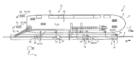
- FIG. 1 shows a plan view of a digging assembly, in accordance with the present invention, burying a pipeline laid on the bed of a body of water;
- FIG. 2 shows a side view of the FIG. 1 digging assembly
- FIG. 3 shows a front view of the FIG. 1 assembly and a trench formed in the bed of the body of water;
- FIG. 4 shows a diagram of typical arching of an in-trench pipeline
- FIG. 5 shows a graph of a boundary curve separating permissible from non-permissible pipeline deformation values
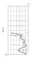
- FIG. 6 shows a graph, in which the Y axis shows the distance of the pipeline from a reference point along the pipeline, and the X axis the depth of the pipeline.
- Number 1 in FIG. 1 indicates as a whole a digging assembly for laying a pipeline 2 in the bed 3 of a body of water 4 , and which, though not exclusively, is particularly suitable for burying a pipeline in shallow water (of less than 10 meters).
- the following description refers specifically to digging assembly 1 operated in post-trenching mode, i.e. in which a trench 5 is dug close to pipeline 2 laid beforehand along a path P on bed 3 of body of water 4 .
- Pipeline 2 extends along path P on bed 3 of body of water 4 , and digging assembly 1 is advanced along path P in a direction D parallel to path P and close to pipeline 2 .
- Digging assembly 1 comprises a support base 6 which, in the example shown, is a powered vessel moved in steps in direction D, parallel to path P; digging devices 7 , 8 , 9 , 10 for forming trench 5 ; at least one backfill device 12 for filling in trench 5 ; a control device 13 ; and at least one grader 14 for modifying the bottom of trench 5 when control device 13 detects any anomalies, attributable to the bottom of trench 5 , in the position of the portion of pipeline 2 laid on the bottom of trench 5 .
- Support base 6 is equipped with a pump assembly PA connected to digging devices 8 , 10 , 11 —which, in the example shown, are dredging devices—and to backfill device 12 to pump the material removed from trench 5 onto support base 6 and to backfill device 12 , which fills in trench 5 once pipeline 2 is laid on the bottom of trench 5 .
- digging devices 8 , 10 , 11 which, in the example shown, are dredging devices—and to backfill device 12 to pump the material removed from trench 5 onto support base 6 and to backfill device 12 , which fills in trench 5 once pipeline 2 is laid on the bottom of trench 5 .
- trench 5 is dug in two consecutive stages by two digging machines 15 , 16 , which comprise respective digging devices 7 , 9 to break up bed 3 of body of water 4 close to—in the example shown, underneath—pipeline 2 ; and respective digging devices 8 , 10 for dredging the material broken up by digging devices 7 , 9 .
- Digging machine 16 operates deeper than and downstream from digging machine 15 in travelling direction D.
- Digging machines 15 , 16 are connected to support base 6 by umbilicals (not shown) by which control signals and operating power are transmitted in known manner.
- the umbilicals allow digging machines 15 , 16 a certain amount of movement with respect to support base 6 , though the positions of digging machines 15 , 16 with respect to support base 6 are more or less constant, and only vary by a few meters along path P.
- Trench 5 is dug beneath pipeline 2 laid on bed 3 of body of water 4 ; and pipeline 2 settles gradually onto the bottom of trench 5 as it is dug.
- pipeline 2 has a portion laid on bed 3 of body of water 4 ; a portion laid on the bottom of trench 5 ; and an unsupported portion inside trench 5 .
- the unsupported portion gradually settles onto the bottom of trench 5 , and support is gradually removed from beneath the portion on bed 3 of body of water 4 .
- the length of the unsupported portion depends on the physical, mechanical, and dimensional characteristics of pipeline 2 , and on the depth of trench 5 . And, on the basis of these parameters, it is possible to determine the point at which pipeline 2 rests on the bottom of trench 5 .
- Digging device 11 comprises a carriage 17 which is movable along pipeline 2 , is located along the unsupported portion of pipeline 2 , and is substantially a dredging device connected to the pump assembly PA on support base 6 .
- Digging device 11 is also connected to support base 6 by an umbilical (not shown), is allowed a limited amount of movement along path P with respect to support base 6 , and is an emergency dredging device, which is operated to remove collapsed sidewall material from the bottom of trench 5 and restore the bottom of trench 5 to design conditions. This is a routine occurrence when working with a loose bed 3 of body of water 4 and a steep-sidewalled trench 5 .
- Control device 13 comprises a control unit 18 on support base 6 ; and sensors 19 , 20 , 21 , 22 , 23 , 24 , 25 connected functionally to control unit 18 , and which are substantially pressure sensors for supplying signals to control unit 18 .
- sensor 19 is fitted to digging machine 15 ; sensor 20 to digging machine 16 ; sensor 21 to carriage 17 of emergency digging device 11 ; sensor 22 to a carriage 26 movable along the portion of pipeline 2 laid on the bottom of trench 5 ; sensors 23 , 24 to respective slides 27 , 28 on bed 3 of body of water 4 ; and sensor 25 to support base 6 .
- Control device 13 comprises a position recognition system 29 —in the example shown, a GPS—for acquiring data related to the position coordinates of digging assembly 1 .
- Position recognition system 29 and control unit 18 are configured to supply a position coordinate X indicating the distance travelled by digging assembly 1 along path P with respect to a reference point on pipeline 2 —normally the trench backfill start point. Given that the component parts of digging assembly 1 are advanced more or less in the same way as and simultaneously with support base 6 , the X coordinate also roughly indicates the position of each of the component parts of digging assembly 1 .
- Sensor 25 on the support base serves to determine atmospheric pressure by which to calibrate the other sensors.
- Sensors 19 , 20 , 21 , 22 , 23 , 34 supply pressure data related to the respective depths of digging machine 15 , digging machine 16 , digging device 11 , carriage 26 , and slides 27 and 28 , to enable control unit 18 to supply respective depth values of digging machine 15 , digging machine 16 , digging device 11 , carriage 26 , and slides 27 , 28 for each X position coordinate.
- control device 13 operates more accurately by acquiring the coordinate of digging machine 15 , the coordinate of digging machine 16 , the coordinate of digging device 11 , the coordinate of carriage 26 , and the coordinates of slides 27 and 28 .
- the above coordinates are relatively easy to acquire by simply adding (or subtracting) a fixed distance of each of the above components to (or from) the X position coordinate value.
- the positions of digging machines 15 and 16 , emergency digging device 11 , carriage 26 and slides 27 and 28 in fact, only vary by a few meters in direction D with respect to support base 6 , so for this purpose may be considered fixed relative positions.
- control device 13 comprises a position recognition system for carriage 26 , and position recognition devices for slides 27 and 28 .
- each digging machine 15 , 16 has its own position recognition device.
- Control device 13 uses the data it acquires to calculate the straightness of pipeline 2 laid on the bottom of trench 5 , or the extent to which arching of pipeline 2 is acceptable; the coverage height of pipeline 2 ; the operating depth of digging machines 15 and 16 ; and the depth of digging machine 11 .
- the above parameters serve to rectify any anomalies detected by control device 13 .
- pipeline 2 When pipeline 2 , or a portion of it, is laid on the bottom of trench 5 , the pipeline assumes a bathymetric profile which depends on the bottom of trench 5 and the mechanical characteristics of pipeline 2 .
- Straightness control ensures pipeline 2 , or rather the portion of it, laid on the bottom of trench 5 has no critical points along its bathymetric profile capable of initiating abnormal deformation which could undermine the structural integrity of pipeline 2 once it is operative.
- pairs of permissible geometric values of pipeline 2 are defined, each pair comprising a permissible variation in depth of pipeline 2 , and a permissible length of deformation along pipeline 2 .
- Arching in this case, in the vertical plane of the pipeline—is considered a critical form of deformation, by possibly causing structural instability of the pipeline.
- An arching model is shown in FIG. 4 .
- pipeline 2 forms an arch, the dimensions of which are defined by two consecutive (in this case, minimum and maximum) relative extremes, and characterized by a variation in depth H, and by a distance L between consecutive relative extremes (from minimum to maximum and/or vice versa). In actual fact, arching extends to a length of roughly twice distance L.
- permissible variations in depth H and distance L are defined according to the physical, mechanical and dimensional characteristics of pipeline 2 , which include the type of material, thickness, and diameter of the pipes used to build pipeline 2 , and the dimensional characteristics of any covering of pipeline 2 .
- FIG. 5 shows an example of pairs of permissible values (zone 1 and zone 2 ).
- the mechanical characteristics of the pipeline and simulation tests show that, below a given distance value L min , the maximum permissible variation in depth is constant and equals a value H max , whereas, above distance value L min the maximum permissible variation in depth increases with distance L.
- Zones 1 and 2 define the permissible values, and zone 3 the non-permissible values.
- the method according to the present invention comprises acquiring data related to the bathymetric profile of the portion of pipeline 2 laid on the bottom of trench 5 at preferably regular intervals.
- This digitized data is processed by control unit 18 and, for easy interpretation, is plotted on a cartesian graph of the type shown in FIG. 6 , in which the Y axis shows position coordinate X 1 and the X axis depth coordinate H 1 .
- Control unit 18 may be equipped with a monitor and printer (not shown) to show the bathymetric profile of the portion of pipeline 2 laid on the bottom of trench 5 .
- the data acquired is the position coordinate X 1 indicating the distance, along path P, between a reference point on pipeline 2 and the acquired point; and depth coordinate H 1 indicating the depth of pipeline 2 at the position coordinate X 1 point.
- Control unit 18 is configured to interpolate the points indicated by position and depth coordinates X 1 and H 1 into a curve, preferably composed of third-order polynomial curves with continuity up to the second derivative at the connecting points of different polynomial curves.
- Control unit 18 is configured to acquire the relative extremes of the curve; calculate the variation in depth H, and distance L between each pair of consecutive relative extremes; and compare the pairs of H and L values with the pairs of permissible values in FIG. 5 .
- Each pair of H and L values indicates the presence of arching of pipeline 2 , and is comparable with the pairs of permissible values.
- Control unit 18 is configured to real-time calculate the H and L data relative to the last relative extreme, and the last acquired position and depth coordinates X 1 and H 1 , which may identify a relative extreme and so indicate a critical condition of pipeline 2 .
- control unit 18 When the acquired H and L data does not fall within the permissible values in FIG. 5 , i.e. within zone 3 in the FIG. 5 graph, control unit 18 emits an error signal E 1 preferably related to the degree of error, i.e. the extent to which the H and L data deviates from the permissible values.
- Error signal E 1 determines an emergency situation, during which digging and backfilling may be suspended, support base 6 stopped in a given position, and the FIG. 1 grader 14 operated to level the bottom of trench 5 .
- Grader 14 is substantially a remotely-operated underwater vehicle connected by umbilicals (not shown) to support base 6 and equipped with dredging tools, which are set up on either side of pipeline 2 to create conditions whereby pipeline 2 sinks further into trench 5 , and so correct the bathymetric profile of pipeline 2 .
- the bottom of trench 5 is preferably levelled before trench 5 is filled in.
- sensor 22 on carriage 26 supplies data relative to depth coordinate H 1 of the top of pipeline 2 ; and sensors 23 and 24 on respective slides 27 and 28 supply data relative to a coordinate H 2 related to the surface depth of bed 3 of body of water 4 .
- sensors 23 , 24 would be enough to measure the depth of bed 3 , but multiple sensors give a more accurate measurement, especially in the event of a highly uneven surface of bed 3 .
- the depth of bed 3 is substantially measured close to path P, so the acquired depth data may be taken as applying to the depth of bed 3 at path P.
- Control unit 18 is configured to calculate the coverage height R of pipeline 2 as the difference between depth coordinate H 1 related to the top of pipeline 2 , and coordinate H 2 related to the depth of bed 3 ; and to compare coverage height R with a threshold value RS defining a set of permissible coverage height R values. When the calculated coverage height R is below threshold value RS, control unit 18 emits an error signal E 2 .
- Depth coordinate H 1 is associated with a position coordinate X 1
- depth coordinate H 2 is associated with a position coordinate X 2 defined by the distance, along path P, between slides 27 , 28 and a reference point on pipeline 2 along path P.
- the subtraction of depth coordinates H 1 and H 2 must be made for respective position coordinate X 1 and X 2 values within a given confidence interval, i.e. relatively close and preferably coincident.
- grader 14 ( FIG. 1 ) intervenes to lower the position of pipeline 2 in trench 5 to such a depth coordinate H 1 that the calculated coverage height R is greater than or equal to threshold value RS; and the sinking of the bottom of trench 5 is monitored to ensure it does not jeopardize the straightness of pipeline 2 .
- Emission of error signal E 2 may also be followed by a signal to digging machines 15 , 16 to correct, if necessary, the digging depth of machines 15 , 16 ( FIG. 1 ).
- control unit 18 acquires the bathymetric profile of bed 3 , and compares it with the bathymetric profile of the portion of pipeline 2 laid on the bottom of trench 5 , to ensure coverage height R falls within permissible values along the whole of path P.
- control device 13 monitors respective depth coordinates H 3 and H 4 of digging machines 15 and 16 to determine conformance with design depths.
- Depth coordinates H 3 and H 4 of digging machines 15 and 16 are related to depth coordinate H 2 of bed 3 of body of water 4 to calculate the depth of trench 5 with respect to the surface of bed 3 and ensure sufficient coverage height R (not shown).
- Depth coordinates H 3 , H 4 are paired with respective position coordinates X 3 , X 4 indicating the distances, along path P, between respective digging machines 15 , 16 and a reference point on pipeline 2 .
- the operating depth of digging machines 15 , 16 must be calculated for pairs of position coordinates X 2 , X 3 and pairs of position coordinates X 2 , X 4 within a confidence interval to obtain significant results.
- Digging assembly 1 provides for monitoring various parameters, and for making any necessary corrections when the monitored parameters fail to conform with design specifications.
- digging assembly 1 provides for laying pipeline 2 in bed 3 of body of water 4 with a sufficient degree of straightness and sufficient coverage height R.
Landscapes
- Engineering & Computer Science (AREA)
- Mining & Mineral Resources (AREA)
- Mechanical Engineering (AREA)
- Civil Engineering (AREA)
- General Engineering & Computer Science (AREA)
- Structural Engineering (AREA)
- Chemical & Material Sciences (AREA)
- Combustion & Propulsion (AREA)
- Ocean & Marine Engineering (AREA)
- Sewage (AREA)
- Supports For Pipes And Cables (AREA)
- Cleaning In General (AREA)
- Rigid Pipes And Flexible Pipes (AREA)
Applications Claiming Priority (4)
| Application Number | Priority Date | Filing Date | Title |
|---|---|---|---|
| IT002044A ITMI20092044A1 (it) | 2009-11-20 | 2009-11-20 | Metodo e gruppo di scavo per disporre una tubazione in un letto di un corpo d'acqua |
| ITMI2009A002044 | 2009-11-20 | ||
| ITMI2009A2044 | 2009-11-20 | ||
| PCT/IB2010/002954 WO2011061605A1 (en) | 2009-11-20 | 2010-11-18 | Digging method and assembly for laying a pipeline in the bed of a body of water |
Publications (2)
| Publication Number | Publication Date |
|---|---|
| US20120288334A1 US20120288334A1 (en) | 2012-11-15 |
| US10240320B2 true US10240320B2 (en) | 2019-03-26 |
Family
ID=42017394
Family Applications (1)
| Application Number | Title | Priority Date | Filing Date |
|---|---|---|---|
| US13/510,880 Active 2033-12-20 US10240320B2 (en) | 2009-11-20 | 2010-11-18 | Digging method and assembly for laying a pipeline in the bed of a body of water |
Country Status (5)
| Country | Link |
|---|---|
| US (1) | US10240320B2 (it) |
| EP (1) | EP2501864B1 (it) |
| EA (1) | EA022638B1 (it) |
| IT (1) | ITMI20092044A1 (it) |
| WO (1) | WO2011061605A1 (it) |
Families Citing this family (6)
| Publication number | Priority date | Publication date | Assignee | Title |
|---|---|---|---|---|
| ITMI20120101A1 (it) * | 2012-01-27 | 2013-07-28 | Saipem Spa | Sistema elettronico, metodo e programma di controllo di una rampa di varo a configurazione variabile di un natante di posa per varare una tubazione su un letto di un corpo d'acqua |
| EP3198176B1 (en) | 2014-09-25 | 2020-04-01 | Saipem S.p.A. | System and method for laying an underwater pipeline on a bed of a body of water |
| ITMI20141880A1 (it) | 2014-11-03 | 2016-05-03 | Saipem Spa | Supporto per tubazione subacquea, sistema e metodo per disporre in opera tale supporto |
| ITUB20152547A1 (it) * | 2015-07-28 | 2017-01-28 | Saipem Spa | Assieme di interramento in una trincea per una condotta continua e metodo di interramento |
| ITUB20153568A1 (it) | 2015-09-11 | 2017-03-11 | Saipem Spa | Metodo e sistema per interrare una tubazione in un letto di un corpo d'acqua |
| US10801644B2 (en) * | 2019-01-28 | 2020-10-13 | Caterpillar Inc. | Pipelaying guidance |
Citations (32)
| Publication number | Priority date | Publication date | Assignee | Title |
|---|---|---|---|---|
| DE249499C (it) | ||||
| US3670514A (en) * | 1970-09-04 | 1972-06-20 | Fluor Corp | Automatic submarine trencher |
| US3877237A (en) * | 1971-08-27 | 1975-04-15 | Norman Offshore Services Inc | Underwater trenching apparatus guidance system |
| GB1492151A (en) | 1975-02-11 | 1977-11-16 | Saipem Spa | Apparatus and method for digging a trench below a submerged pipeline or cable |
| US4087981A (en) * | 1971-08-27 | 1978-05-09 | Norman Offshore Services Inc. | Buoyant self-propelled underwater trenching apparatus |
| US4149326A (en) * | 1975-02-11 | 1979-04-17 | Saipem S.P.A. | Machine for digging a trench beneath a submerged pipeline |
| US4214387A (en) * | 1978-06-01 | 1980-07-29 | Brown & Root, Inc. | Trenching apparatus and method |
| US4229809A (en) * | 1979-01-29 | 1980-10-21 | Sperry Corporation | Acoustic under sea position measurement system |
| US4586850A (en) * | 1983-07-12 | 1986-05-06 | Norman Robert M | Underwater trenching system |
| US4759138A (en) * | 1984-12-19 | 1988-07-26 | Soil Machine Dynamics Limited | Plow steering system |
| US4986697A (en) * | 1984-05-07 | 1991-01-22 | Lyntech Corporation | Marine pipeline trenching plow for simultaneous pipe laying and entrenchment |
| US5689475A (en) * | 1994-05-30 | 1997-11-18 | Port Autonome De Bordeaux | Nautical apparatus to conduct reconnaissance missions of a site, particularly bathymetric surveys |
| US5691903A (en) * | 1995-09-08 | 1997-11-25 | The United States Of America As Represented By The Secretary Of The Navy | Integrated cable navigation and control system |
| US5947051A (en) * | 1997-06-04 | 1999-09-07 | Geiger; Michael B. | Underwater self-propelled surface adhering robotically operated vehicle |
| US6022173A (en) * | 1994-01-13 | 2000-02-08 | Saxon; Saint E. | Underwater trenching system |
| US20010010782A1 (en) * | 1997-04-03 | 2001-08-02 | Giovanni Corbetta | Method and apparatus for connecting underwater conduits |
| US20020071724A1 (en) * | 1997-09-05 | 2002-06-13 | Reece Alan Richard | Submarine plough |
| US6719494B1 (en) * | 2000-10-19 | 2004-04-13 | Coelexip, S.A. | Cable and pipe burial apparatus and method |
| US6771563B1 (en) * | 2000-03-20 | 2004-08-03 | Bernard Francois | Apparatus for deploying a load to an underwater target position with enhanced accuracy and a method to control such apparatus |
| US6821054B2 (en) * | 2002-08-19 | 2004-11-23 | Horizon Vessels, Inc. | Method and system for laying pipe through the use of a plow |
| US6837653B1 (en) * | 1999-09-21 | 2005-01-04 | The Engineering Business Ltd. | Ploughs |
| WO2005005736A2 (en) | 2003-07-04 | 2005-01-20 | Saipem S.P.A. | Trenching apparatus and method |
| US20050232705A1 (en) * | 2002-12-20 | 2005-10-20 | Saipem S.P.A | Process and system for the installation of pipelines in shallow or very shallow water |
| US7117091B2 (en) * | 2003-09-24 | 2006-10-03 | Institut Francais Du Petrole | Method for simulating the deposition of a sedimentary sequence in a basin |
| JP2008208529A (ja) | 2007-02-23 | 2008-09-11 | Ohmoto Gumi Co Ltd | バックホウ浚渫船の施工支援システムによる水中施工方法 |
| US20100128561A1 (en) * | 2006-11-14 | 2010-05-27 | Statoil Asa | Seafloor-following streamer |
| US20100152901A1 (en) * | 2008-12-16 | 2010-06-17 | Hydril Usa Manufacturing Llc | Position Data Based Method, Interface and Device for Blowout Preventer |
| US20100157736A1 (en) * | 2007-06-15 | 2010-06-24 | University Of Limerick | Method and apparatus for determining the topography of a seafloor and a vessel comprising the apparatus |
| US20100182161A1 (en) * | 2007-04-28 | 2010-07-22 | Halliburton Energy Services, Inc. | Wireless telemetry repeater systems and methods |
| US8066450B2 (en) * | 2006-08-10 | 2011-11-29 | Saipem S.P.A. | Device and method for the towing of underwater pipelines |
| US8328466B1 (en) * | 2010-09-13 | 2012-12-11 | The United States Of America As Represented By The Secretary Of The Navy | Buoyancy stabilized underwater plow and methods for use |
| US8360685B1 (en) * | 2010-09-07 | 2013-01-29 | The United States Of America As Represented By The Secretary Of The Navy | Autonomous underwater plow and method of use |
Family Cites Families (5)
| Publication number | Priority date | Publication date | Assignee | Title |
|---|---|---|---|---|
| US3893404A (en) * | 1974-03-25 | 1975-07-08 | Skagit Corp | Pull-ahead winch control system |
| JPS5337550B2 (it) * | 1974-10-02 | 1978-10-09 | ||
| DD249499A1 (de) * | 1986-05-30 | 1987-09-09 | Strassen & Tiefbau Kom | Vorrichtung zum hydrostatischen tiefenmessen |
| US4793183A (en) * | 1987-08-06 | 1988-12-27 | Henkels & Mccoy, Inc. | Automated positioning/drawing system and method of use |
| GB2348448A (en) | 1999-04-01 | 2000-10-04 | Sonsub Int Ltd | Forming an underwater trench using separate rov and trenching apparatus |
-
2009
- 2009-11-20 IT IT002044A patent/ITMI20092044A1/it unknown
-
2010
- 2010-11-18 EA EA201290367A patent/EA022638B1/ru not_active IP Right Cessation
- 2010-11-18 WO PCT/IB2010/002954 patent/WO2011061605A1/en active Application Filing
- 2010-11-18 EP EP10807349.5A patent/EP2501864B1/en active Active
- 2010-11-18 US US13/510,880 patent/US10240320B2/en active Active
Patent Citations (32)
| Publication number | Priority date | Publication date | Assignee | Title |
|---|---|---|---|---|
| DE249499C (it) | ||||
| US3670514A (en) * | 1970-09-04 | 1972-06-20 | Fluor Corp | Automatic submarine trencher |
| US3877237A (en) * | 1971-08-27 | 1975-04-15 | Norman Offshore Services Inc | Underwater trenching apparatus guidance system |
| US4087981A (en) * | 1971-08-27 | 1978-05-09 | Norman Offshore Services Inc. | Buoyant self-propelled underwater trenching apparatus |
| GB1492151A (en) | 1975-02-11 | 1977-11-16 | Saipem Spa | Apparatus and method for digging a trench below a submerged pipeline or cable |
| US4149326A (en) * | 1975-02-11 | 1979-04-17 | Saipem S.P.A. | Machine for digging a trench beneath a submerged pipeline |
| US4214387A (en) * | 1978-06-01 | 1980-07-29 | Brown & Root, Inc. | Trenching apparatus and method |
| US4229809A (en) * | 1979-01-29 | 1980-10-21 | Sperry Corporation | Acoustic under sea position measurement system |
| US4586850A (en) * | 1983-07-12 | 1986-05-06 | Norman Robert M | Underwater trenching system |
| US4986697A (en) * | 1984-05-07 | 1991-01-22 | Lyntech Corporation | Marine pipeline trenching plow for simultaneous pipe laying and entrenchment |
| US4759138A (en) * | 1984-12-19 | 1988-07-26 | Soil Machine Dynamics Limited | Plow steering system |
| US6022173A (en) * | 1994-01-13 | 2000-02-08 | Saxon; Saint E. | Underwater trenching system |
| US5689475A (en) * | 1994-05-30 | 1997-11-18 | Port Autonome De Bordeaux | Nautical apparatus to conduct reconnaissance missions of a site, particularly bathymetric surveys |
| US5691903A (en) * | 1995-09-08 | 1997-11-25 | The United States Of America As Represented By The Secretary Of The Navy | Integrated cable navigation and control system |
| US20010010782A1 (en) * | 1997-04-03 | 2001-08-02 | Giovanni Corbetta | Method and apparatus for connecting underwater conduits |
| US5947051A (en) * | 1997-06-04 | 1999-09-07 | Geiger; Michael B. | Underwater self-propelled surface adhering robotically operated vehicle |
| US20020071724A1 (en) * | 1997-09-05 | 2002-06-13 | Reece Alan Richard | Submarine plough |
| US6837653B1 (en) * | 1999-09-21 | 2005-01-04 | The Engineering Business Ltd. | Ploughs |
| US6771563B1 (en) * | 2000-03-20 | 2004-08-03 | Bernard Francois | Apparatus for deploying a load to an underwater target position with enhanced accuracy and a method to control such apparatus |
| US6719494B1 (en) * | 2000-10-19 | 2004-04-13 | Coelexip, S.A. | Cable and pipe burial apparatus and method |
| US6821054B2 (en) * | 2002-08-19 | 2004-11-23 | Horizon Vessels, Inc. | Method and system for laying pipe through the use of a plow |
| US20050232705A1 (en) * | 2002-12-20 | 2005-10-20 | Saipem S.P.A | Process and system for the installation of pipelines in shallow or very shallow water |
| WO2005005736A2 (en) | 2003-07-04 | 2005-01-20 | Saipem S.P.A. | Trenching apparatus and method |
| US7117091B2 (en) * | 2003-09-24 | 2006-10-03 | Institut Francais Du Petrole | Method for simulating the deposition of a sedimentary sequence in a basin |
| US8066450B2 (en) * | 2006-08-10 | 2011-11-29 | Saipem S.P.A. | Device and method for the towing of underwater pipelines |
| US20100128561A1 (en) * | 2006-11-14 | 2010-05-27 | Statoil Asa | Seafloor-following streamer |
| JP2008208529A (ja) | 2007-02-23 | 2008-09-11 | Ohmoto Gumi Co Ltd | バックホウ浚渫船の施工支援システムによる水中施工方法 |
| US20100182161A1 (en) * | 2007-04-28 | 2010-07-22 | Halliburton Energy Services, Inc. | Wireless telemetry repeater systems and methods |
| US20100157736A1 (en) * | 2007-06-15 | 2010-06-24 | University Of Limerick | Method and apparatus for determining the topography of a seafloor and a vessel comprising the apparatus |
| US20100152901A1 (en) * | 2008-12-16 | 2010-06-17 | Hydril Usa Manufacturing Llc | Position Data Based Method, Interface and Device for Blowout Preventer |
| US8360685B1 (en) * | 2010-09-07 | 2013-01-29 | The United States Of America As Represented By The Secretary Of The Navy | Autonomous underwater plow and method of use |
| US8328466B1 (en) * | 2010-09-13 | 2012-12-11 | The United States Of America As Represented By The Secretary Of The Navy | Buoyancy stabilized underwater plow and methods for use |
Non-Patent Citations (3)
| Title |
|---|
| http://web.archive.org/web/20070102222126/http://www.soest.hawaii.edu/gmt/ Wessel and Smith, Sep. 5, 2006. * |
| International Search Report and Written Opinion for International Appl. No. PCT/IB2010/002954, European Patent Office, The Netherlands, dated Mar. 25, 2011, 11 pages. |
| M. Sinclair, Correcting Deep Spans in Subsea Pipelines, chap. 25 in PIPLINE 5, pp. 163-165 (Nov. 1985). |
Also Published As
| Publication number | Publication date |
|---|---|
| EA022638B1 (ru) | 2016-02-29 |
| WO2011061605A1 (en) | 2011-05-26 |
| US20120288334A1 (en) | 2012-11-15 |
| EP2501864B1 (en) | 2015-01-07 |
| EA201290367A1 (ru) | 2012-11-30 |
| ITMI20092044A1 (it) | 2011-05-21 |
| EP2501864A1 (en) | 2012-09-26 |
Similar Documents
| Publication | Publication Date | Title |
|---|---|---|
| US10240320B2 (en) | Digging method and assembly for laying a pipeline in the bed of a body of water | |
| CA2886827C (en) | System and method for determining deformed pipe geometry | |
| US10626563B2 (en) | Self-propelled construction machine and method for operating a self-propelled construction machine | |
| US10435865B2 (en) | Trenching assembly for laying in a trench a continuous pipeline and trenching method | |
| US9605532B2 (en) | Method and device for determining a drill bit's position in a borehole | |
| US11280174B2 (en) | System and method for determining the shape and position of an underwater riser | |
| CN104696589B (zh) | 深水海底管线终止铺设的方法 | |
| CN105783925A (zh) | 一种用于凿岩台车的车体定位系统及方法 | |
| JP2009221802A (ja) | シールド掘進機の掘削断面土層判定装置および判定方法 | |
| JP6507023B2 (ja) | 内空変位計測方法 | |
| US20040013471A1 (en) | Subsea pipeline touchdown monitoring | |
| JP2019094699A (ja) | 路面切削方法および路面切削機 | |
| KR20190114781A (ko) | 전자기파 분석을 통한 지하구조물과 공동형상 맵핑장치 및 그 맵핑방법 | |
| CN111504244A (zh) | 海底管道在位状态的检测方法及检测系统 | |
| JP2019090269A (ja) | 地中変位測定方法 | |
| JP2014228305A (ja) | 異鋼種連続鋳造における鋳片継目部の検出方法 | |
| JP6326335B2 (ja) | 地山状況予測方法 | |
| US11248460B2 (en) | Detecting a flood front in a formation | |
| JP7154944B2 (ja) | 設置位置計測装置及び設置位置計測方法 | |
| JP7174671B2 (ja) | 掘削底面監視システム | |
| NL1012908C2 (nl) | Werkwijze voor het bepalen van de geometrie van een onder water liggend lichaam. | |
| CN104652397A (zh) | 一种深水基槽回淤监测方法及系统 | |
| Adisty et al. | Detailed Metal Loss Assessment of In-line Inspection (UT) Raw Data for Offshore Pipelines | |
| JP2021060243A (ja) | 監視システム |
Legal Events
| Date | Code | Title | Description |
|---|---|---|---|
| AS | Assignment |
Owner name: SAIPEM S.P.A., ITALY Free format text: ASSIGNMENT OF ASSIGNORS INTEREST;ASSIGNORS:BELLIN, MASSIMO;MASSARI, GIOVANNI;BONEL, PAOLO;REEL/FRAME:028670/0373 Effective date: 20120620 |
|
| STCF | Information on status: patent grant |
Free format text: PATENTED CASE |
|
| MAFP | Maintenance fee payment |
Free format text: PAYMENT OF MAINTENANCE FEE, 4TH YEAR, LARGE ENTITY (ORIGINAL EVENT CODE: M1551); ENTITY STATUS OF PATENT OWNER: LARGE ENTITY Year of fee payment: 4 |