US1023908A - Box. - Google Patents
Box. Download PDFInfo
- Publication number
- US1023908A US1023908A US45473508A US1908454735A US1023908A US 1023908 A US1023908 A US 1023908A US 45473508 A US45473508 A US 45473508A US 1908454735 A US1908454735 A US 1908454735A US 1023908 A US1023908 A US 1023908A
- Authority
- US
- United States
- Prior art keywords
- box
- wall
- walls
- edge
- hinged
- Prior art date
- Legal status (The legal status is an assumption and is not a legal conclusion. Google has not performed a legal analysis and makes no representation as to the accuracy of the status listed.)
- Expired - Lifetime
Links
- 210000002105 tongue Anatomy 0.000 description 5
- 230000015572 biosynthetic process Effects 0.000 description 2
- 238000010276 construction Methods 0.000 description 2
- 241000755266 Kathetostoma giganteum Species 0.000 description 1
Images
Classifications
-
- B—PERFORMING OPERATIONS; TRANSPORTING
- B65—CONVEYING; PACKING; STORING; HANDLING THIN OR FILAMENTARY MATERIAL
- B65D—CONTAINERS FOR STORAGE OR TRANSPORT OF ARTICLES OR MATERIALS, e.g. BAGS, BARRELS, BOTTLES, BOXES, CANS, CARTONS, CRATES, DRUMS, JARS, TANKS, HOPPERS, FORWARDING CONTAINERS; ACCESSORIES, CLOSURES, OR FITTINGS THEREFOR; PACKAGING ELEMENTS; PACKAGES
- B65D9/00—Containers having bodies formed by interconnecting or uniting two or more rigid, or substantially rigid, components made wholly or mainly of wood or substitutes therefor
- B65D9/12—Containers having bodies formed by interconnecting or uniting two or more rigid, or substantially rigid, components made wholly or mainly of wood or substitutes therefor collapsible, e.g. with all parts detachable
- B65D9/14—Containers having bodies formed by interconnecting or uniting two or more rigid, or substantially rigid, components made wholly or mainly of wood or substitutes therefor collapsible, e.g. with all parts detachable with all parts hinged together
Definitions
- This invent-ion relates to boxes and more particularly to that class which are collapsible.
- the invention relates to that class of collapsible boxes in which interlocking flanges are provided alongthe vertical edges of the ends and sides of the box and a spring locking tongue which automatically springs into place to hold the sides and ends against folding.
- interlocking flanges are provided alongthe vertical edges of the ends and sides of the box and a spring locking tongue which automatically springs into place to hold the sides and ends against folding.
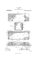
- Figure l is a front elevation of the box.
- Fig. 2 is an end view of the box embodying my invention.
- Fig. 3 is a vertical sectional view through the box showing the spring tongue in locked position.
- Fig. 4f is a vertical sectional view therethrough showing the box in folded position.
- the box embodying my invention comprises a bottom which is indicated by the numeral 10, a front side 11 which is hinged at its lower edge to the forward edge of the bottom, a rear side or wall 12 which is hinged at its lower edge to the rear edge of the bottom, and a top which is hinged at its rear edge to the upper edge of the rear side of the box, the hinge connection between the several walls of the bo-x mentioned being had preferably by means of two flexible straps which are indicated by the numeral 14 and are riveted or otherwise i secured tothe said walls of the box and extended around the same, the straps being provided at their endswhich terminate upon the front wall of the box with buckles 15 and the other ends of the straps being formed with lthe usual openings for the engagement therein of the bills of the buckles, whereby the box may be held closed.
- the box also includes in its struct-ure ends which are indicated by the numeral 16 and which are hinged as at 17 tothe vertical edges of the front side of the box, they being adapted to be folded in to lie against the inner side of the said front wall as will be presently explained.
- a plate 18 Secured upon the inner face of tlie'rear wall of the box at each end thereof is a plate 18 which at its outer vertical edge is bent back upon itself as indicated by the numeral 19, there being a plate 20 secured upon each of the ends of the box at the free vertical edge thereof and formed at its outer vertical edge with a rightangularly bent flange 21 which, when the box is opened and filled, is engaged between the body of the corresponding plate 18 and the back bent edge portion thereof, the four side walls of the box being in this manner held against collapsing.
- spring detents 23 which are secured one adjacent each end of the rear side of t-he box and which have their free ends directed toward the end edges of the said rear wall, they being normally sprung out from the said wall of the box so as to automatically engage at their free ends with the corresponding end walls of the box as is yclearly shown in the horizontal sectional view of the drawings.
- the plates 18 are each centrally formed with a longitudinal slot 29 adapted to receive the free ends of the detents when it is desired'to unlock the box.
- a box comprising in combination, a bottom, front and rear side walls hinged to the bot-tom, a top hinged to the upper edge of one of the side walls, and walls hinged to the rear side wall to swing inwardly, plates se cured to the inner face of the end walls and having outwardly turned flanges extending over the forward edges of said walls and in spaced relation thereto and to the front side wall, plates carried by the inner face of the front side wall having resilient louter ends adapted to engage the flange portions of the first mentioned plates, and spring detente carried by the inner face of the front wall adapted to engage the plates carried by the end walls to look the latter against inward movements, said second mentioned plates being centrally formed with longitudinal slots for receiving the free ends of the detents when the latter are disengaged from the iirst inent-ioned plates.
Landscapes
- Engineering & Computer Science (AREA)
- Life Sciences & Earth Sciences (AREA)
- Wood Science & Technology (AREA)
- Mechanical Engineering (AREA)
- Rigid Containers With Two Or More Constituent Elements (AREA)
Description
A. F. WILGOX.
l APPLICATION FILED SEPT. 25, 1908. 1 ,023,908. Patented Apr. 23, 1 912.
coLuMBlA PLANQGRAPI?" C0..WASHINOTON, D. c.
ARTHUR WILCOX, OF KALISPELL, MONTANA.
BOX.`
Specification of Letters Patent.
Application filed September 25, 1908.
Patented Apr. 23, 1912.
Serial No. 454,735.
To all whom t may concern.'
Be it known that I, ARTHUR F. WILCox, a citizen of the United States, residing at Kalispell, in the county of Flathead, State of Montana, have invented certain new and useful Improvements in Boxes; and I do hereby declare the following to be a full, clear, and exact description of the invention, such as will enable others skilled in the art to which it appertains to make and use the same.
This invent-ion relates to boxes and more particularly to that class which are collapsible.
More specifically speaking, the invention relates to that class of collapsible boxes in which interlocking flanges are provided alongthe vertical edges of the ends and sides of the box and a spring locking tongue which automatically springs into place to hold the sides and ends against folding. I-Ieretofore, it has been customary in such constructions to form in the sides or ends of the box recesses into which the tongues may be sprung when it is desired to fold the box, but I have found that such constructions are undesirable as the formation of such recesses involves considerable loss of time and labor and as a result, I have conceived the'idea of forming an opening in the flange plate which is secured upon that wall of the box upon which the spring tongue is fixed so that the thickness of the tongue may be received in the opening and the formation of the usual recesses obviated.
In the accompanying drawings, Figure l is a front elevation of the box. Fig. 2 is an end view of the box embodying my invention. Fig. 3 is a vertical sectional view through the box showing the spring tongue in locked position. Fig. 4f is a vertical sectional view therethrough showing the box in folded position.
As shown in the drawings, the box embodying my invention comprises a bottom which is indicated by the numeral 10, a front side 11 which is hinged at its lower edge to the forward edge of the bottom,a rear side or wall 12 which is hinged at its lower edge to the rear edge of the bottom, and a top which is hinged at its rear edge to the upper edge of the rear side of the box, the hinge connection between the several walls of the bo-x mentioned being had preferably by means of two flexible straps which are indicated by the numeral 14 and are riveted or otherwise i secured tothe said walls of the box and extended around the same, the straps being provided at their endswhich terminate upon the front wall of the box with buckles 15 and the other ends of the straps being formed with lthe usual openings for the engagement therein of the bills of the buckles, whereby the box may be held closed. The box also includes in its struct-ure ends which are indicated by the numeral 16 and which are hinged as at 17 tothe vertical edges of the front side of the box, they being adapted to be folded in to lie against the inner side of the said front wall as will be presently explained. Secured upon the inner face of tlie'rear wall of the box at each end thereof is a plate 18 which at its outer vertical edge is bent back upon itself as indicated by the numeral 19, there being a plate 20 secured upon each of the ends of the box at the free vertical edge thereof and formed at its outer vertical edge with a rightangularly bent flange 21 which, when the box is opened and filled, is engaged between the body of the corresponding plate 18 and the back bent edge portion thereof, the four side walls of the box being in this manner held against collapsing.
In order to prevent the interlocking flanges above described becoming disengaged one from t-he other, I have provided spring detents 23 which are secured one adjacent each end of the rear side of t-he box and which have their free ends directed toward the end edges of the said rear wall, they being normally sprung out from the said wall of the box so as to automatically engage at their free ends with the corresponding end walls of the box as is yclearly shown in the horizontal sectional view of the drawings. The plates 18 are each centrally formed with a longitudinal slot 29 adapted to receive the free ends of the detents when it is desired'to unlock the box.
In folding t-he box, the ends are folded upon the front wall and the said wall then turned back against the underside of the bottom the said bottom and the end walls being then folded upon the rear wall so that the end walls will be between the said rear wall and the bottom, the top being finally folded back upon the rear wall.
What is claimed is:
A box comprising in combination, a bottom, front and rear side walls hinged to the bot-tom, a top hinged to the upper edge of one of the side walls, and walls hinged to the rear side wall to swing inwardly, plates se cured to the inner face of the end walls and having outwardly turned flanges extending over the forward edges of said walls and in spaced relation thereto and to the front side wall, plates carried by the inner face of the front side wall having resilient louter ends adapted to engage the flange portions of the first mentioned plates, and spring detente carried by the inner face of the front wall adapted to engage the plates carried by the end walls to look the latter against inward movements, said second mentioned plates being centrally formed with longitudinal slots for receiving the free ends of the detents when the latter are disengaged from the iirst inent-ioned plates.
In testimony whereof, I afiiX my signature, in presence of two witnesses.
ARTHUR F. WILCOX. lVitnesses D. A. STOCKING,
ERNEST M. CHILD.
Copies of this patent may be obtained for five cents each, by addressing the Commissioner of Patents Washington, D. C.
Priority Applications (1)
| Application Number | Priority Date | Filing Date | Title |
|---|---|---|---|
| US45473508A US1023908A (en) | 1908-09-25 | 1908-09-25 | Box. |
Applications Claiming Priority (1)
| Application Number | Priority Date | Filing Date | Title |
|---|---|---|---|
| US45473508A US1023908A (en) | 1908-09-25 | 1908-09-25 | Box. |
Publications (1)
| Publication Number | Publication Date |
|---|---|
| US1023908A true US1023908A (en) | 1912-04-23 |
Family
ID=3092204
Family Applications (1)
| Application Number | Title | Priority Date | Filing Date |
|---|---|---|---|
| US45473508A Expired - Lifetime US1023908A (en) | 1908-09-25 | 1908-09-25 | Box. |
Country Status (1)
| Country | Link |
|---|---|
| US (1) | US1023908A (en) |
-
1908
- 1908-09-25 US US45473508A patent/US1023908A/en not_active Expired - Lifetime
Similar Documents
| Publication | Publication Date | Title |
|---|---|---|
| US425188A (en) | riedell | |
| US1302361A (en) | Folding paper box. | |
| US1249097A (en) | Box. | |
| US922334A (en) | One-piece folding suit case or box. | |
| US696243A (en) | Crate or box. | |
| US735906A (en) | Folding box or crate. | |
| US504824A (en) | Folding paper box | |
| US705953A (en) | Knockdown box. | |
| US752880A (en) | Folding box | |
| US722317A (en) | Traveling-case. | |
| US377813A (en) | Knockdown box | |
| US480914A (en) | Folding coop or crate | |
| US680105A (en) | Folding paper box. | |
| US762760A (en) | Folding box. | |
| US1152145A (en) | Folding box or case. | |
| US636302A (en) | Box. | |
| US783805A (en) | Folding box. | |
| US554140A (en) | William d | |
| US371230A (en) | Paper box | |
| US893870A (en) | Collapsible box. | |
| US945797A (en) | Folding or collapsible box, case, and the like. | |
| US519451A (en) | Paper box | |
| US1127902A (en) | Box construction. | |
| US1106946A (en) | Receptacle. | |
| US997116A (en) | Folding box. |