US10216112B2 - Image forming apparatus - Google Patents
Image forming apparatus Download PDFInfo
- Publication number
- US10216112B2 US10216112B2 US15/653,218 US201715653218A US10216112B2 US 10216112 B2 US10216112 B2 US 10216112B2 US 201715653218 A US201715653218 A US 201715653218A US 10216112 B2 US10216112 B2 US 10216112B2
- Authority
- US
- United States
- Prior art keywords
- time
- image forming
- transfer member
- cleaning
- forming apparatus
- Prior art date
- Legal status (The legal status is an assumption and is not a legal conclusion. Google has not performed a legal analysis and makes no representation as to the accuracy of the status listed.)
- Active
Links
- 238000004140 cleaning Methods 0.000 claims abstract description 251
- 238000012546 transfer Methods 0.000 claims abstract description 210
- 238000005259 measurement Methods 0.000 claims description 25
- 238000012840 feeding operation Methods 0.000 claims description 5
- 239000000428 dust Substances 0.000 description 98
- 238000000034 method Methods 0.000 description 55
- 230000007547 defect Effects 0.000 description 38
- 238000011161 development Methods 0.000 description 34
- 230000008569 process Effects 0.000 description 28
- 241000519995 Stachys sylvatica Species 0.000 description 19
- 230000000694 effects Effects 0.000 description 19
- 230000015572 biosynthetic process Effects 0.000 description 16
- 230000002093 peripheral effect Effects 0.000 description 11
- 238000002474 experimental method Methods 0.000 description 10
- 230000000052 comparative effect Effects 0.000 description 8
- 239000007787 solid Substances 0.000 description 8
- 238000010586 diagram Methods 0.000 description 7
- 230000008859 change Effects 0.000 description 6
- 238000003825 pressing Methods 0.000 description 6
- 239000002699 waste material Substances 0.000 description 6
- XEEYBQQBJWHFJM-UHFFFAOYSA-N Iron Chemical compound [Fe] XEEYBQQBJWHFJM-UHFFFAOYSA-N 0.000 description 4
- 238000001514 detection method Methods 0.000 description 4
- 239000000463 material Substances 0.000 description 4
- 229910052751 metal Inorganic materials 0.000 description 4
- 239000002184 metal Substances 0.000 description 4
- 230000008021 deposition Effects 0.000 description 3
- 229910052782 aluminium Inorganic materials 0.000 description 2
- XAGFODPZIPBFFR-UHFFFAOYSA-N aluminium Chemical compound [Al] XAGFODPZIPBFFR-UHFFFAOYSA-N 0.000 description 2
- 230000008901 benefit Effects 0.000 description 2
- 239000003795 chemical substances by application Substances 0.000 description 2
- 229910052742 iron Inorganic materials 0.000 description 2
- 230000010355 oscillation Effects 0.000 description 2
- 230000004044 response Effects 0.000 description 2
- 230000000630 rising effect Effects 0.000 description 2
- 238000012795 verification Methods 0.000 description 2
- 230000002950 deficient Effects 0.000 description 1
- 230000007613 environmental effect Effects 0.000 description 1
- 239000000835 fiber Substances 0.000 description 1
- 238000003384 imaging method Methods 0.000 description 1
- 238000012423 maintenance Methods 0.000 description 1
- 230000007246 mechanism Effects 0.000 description 1
- 238000012986 modification Methods 0.000 description 1
- 230000004048 modification Effects 0.000 description 1
- 229920006395 saturated elastomer Polymers 0.000 description 1
- 238000011144 upstream manufacturing Methods 0.000 description 1
Images


Classifications
-
- G—PHYSICS
- G03—PHOTOGRAPHY; CINEMATOGRAPHY; ANALOGOUS TECHNIQUES USING WAVES OTHER THAN OPTICAL WAVES; ELECTROGRAPHY; HOLOGRAPHY
- G03G—ELECTROGRAPHY; ELECTROPHOTOGRAPHY; MAGNETOGRAPHY
- G03G21/00—Arrangements not provided for by groups G03G13/00 - G03G19/00, e.g. cleaning, elimination of residual charge
- G03G21/0005—Arrangements not provided for by groups G03G13/00 - G03G19/00, e.g. cleaning, elimination of residual charge for removing solid developer or debris from the electrographic recording medium
- G03G21/0064—Arrangements not provided for by groups G03G13/00 - G03G19/00, e.g. cleaning, elimination of residual charge for removing solid developer or debris from the electrographic recording medium using the developing unit, e.g. cleanerless or multi-cycle apparatus
-
- G—PHYSICS
- G03—PHOTOGRAPHY; CINEMATOGRAPHY; ANALOGOUS TECHNIQUES USING WAVES OTHER THAN OPTICAL WAVES; ELECTROGRAPHY; HOLOGRAPHY
- G03G—ELECTROGRAPHY; ELECTROPHOTOGRAPHY; MAGNETOGRAPHY
- G03G15/00—Apparatus for electrographic processes using a charge pattern
- G03G15/02—Apparatus for electrographic processes using a charge pattern for laying down a uniform charge, e.g. for sensitising; Corona discharge devices
- G03G15/0208—Apparatus for electrographic processes using a charge pattern for laying down a uniform charge, e.g. for sensitising; Corona discharge devices by contact, friction or induction, e.g. liquid charging apparatus
- G03G15/0216—Apparatus for electrographic processes using a charge pattern for laying down a uniform charge, e.g. for sensitising; Corona discharge devices by contact, friction or induction, e.g. liquid charging apparatus by bringing a charging member into contact with the member to be charged, e.g. roller, brush chargers
- G03G15/0225—Apparatus for electrographic processes using a charge pattern for laying down a uniform charge, e.g. for sensitising; Corona discharge devices by contact, friction or induction, e.g. liquid charging apparatus by bringing a charging member into contact with the member to be charged, e.g. roller, brush chargers provided with means for cleaning the charging member
-
- G—PHYSICS
- G03—PHOTOGRAPHY; CINEMATOGRAPHY; ANALOGOUS TECHNIQUES USING WAVES OTHER THAN OPTICAL WAVES; ELECTROGRAPHY; HOLOGRAPHY
- G03G—ELECTROGRAPHY; ELECTROPHOTOGRAPHY; MAGNETOGRAPHY
- G03G15/00—Apparatus for electrographic processes using a charge pattern
- G03G15/04—Apparatus for electrographic processes using a charge pattern for exposing, i.e. imagewise exposure by optically projecting the original image on a photoconductive recording material
- G03G15/043—Apparatus for electrographic processes using a charge pattern for exposing, i.e. imagewise exposure by optically projecting the original image on a photoconductive recording material with means for controlling illumination or exposure
-
- G—PHYSICS
- G03—PHOTOGRAPHY; CINEMATOGRAPHY; ANALOGOUS TECHNIQUES USING WAVES OTHER THAN OPTICAL WAVES; ELECTROGRAPHY; HOLOGRAPHY
- G03G—ELECTROGRAPHY; ELECTROPHOTOGRAPHY; MAGNETOGRAPHY
- G03G15/00—Apparatus for electrographic processes using a charge pattern
- G03G15/06—Apparatus for electrographic processes using a charge pattern for developing
- G03G15/08—Apparatus for electrographic processes using a charge pattern for developing using a solid developer, e.g. powder developer
- G03G15/0822—Arrangements for preparing, mixing, supplying or dispensing developer
- G03G15/0865—Arrangements for supplying new developer
- G03G15/0867—Arrangements for supplying new developer cylindrical developer cartridges, e.g. toner bottles for the developer replenishing opening
- G03G15/0868—Toner cartridges fulfilling a continuous function within the electrographic apparatus during the use of the supplied developer material, e.g. toner discharge on demand, storing residual toner, acting as an active closure for the developer replenishing opening
-
- G—PHYSICS
- G03—PHOTOGRAPHY; CINEMATOGRAPHY; ANALOGOUS TECHNIQUES USING WAVES OTHER THAN OPTICAL WAVES; ELECTROGRAPHY; HOLOGRAPHY
- G03G—ELECTROGRAPHY; ELECTROPHOTOGRAPHY; MAGNETOGRAPHY
- G03G15/00—Apparatus for electrographic processes using a charge pattern
- G03G15/01—Apparatus for electrographic processes using a charge pattern for producing multicoloured copies
- G03G15/0142—Structure of complete machines
- G03G15/0178—Structure of complete machines using more than one reusable electrographic recording member, e.g. one for every monocolour image
- G03G15/0189—Structure of complete machines using more than one reusable electrographic recording member, e.g. one for every monocolour image primary transfer to an intermediate transfer belt
-
- G—PHYSICS
- G03—PHOTOGRAPHY; CINEMATOGRAPHY; ANALOGOUS TECHNIQUES USING WAVES OTHER THAN OPTICAL WAVES; ELECTROGRAPHY; HOLOGRAPHY
- G03G—ELECTROGRAPHY; ELECTROPHOTOGRAPHY; MAGNETOGRAPHY
- G03G2215/00—Apparatus for electrophotographic processes
- G03G2215/01—Apparatus for electrophotographic processes for producing multicoloured copies
- G03G2215/0151—Apparatus for electrophotographic processes for producing multicoloured copies characterised by the technical problem
- G03G2215/0158—Colour registration
- G03G2215/0161—Generation of registration marks
Definitions
- the present invention relates to image forming apparatuses including a cleaner-less printer, a cleaner-less copier, and a cleaner-less facsimile.
- an image forming apparatus having a configuration which is a so-called “cleaner-less process (cleaner-less method)” in which residual transfer toner on a photosensitive member is removed from the photosensitive member by “cleaning performed concurrently with development (development concurrent cleaning)” by a developing device and is collected by the developing device to be reused has been developed (Japanese Patent Laid-Open No. 8-137368).
- the development concurrent cleaning is a method for collecting toner which slightly remains on a photosensitive member after transfer at a time of development in a next process onwards in accordance with a potential difference (Vback) between a direct-current voltage to be applied to a developing device and a surface potential of the photosensitive member.
- Vback potential difference
- this method the residual transfer toner is used in the next process onwards after being collected by the developing device, and therefore, waste toner is not generated and simple maintenance is attained. Furthermore, this method has an advantage also in terms of a space since the image forming apparatus is cleaner-less, and therefore, a size of the image forming apparatus may be considerably reduced.
- Dust in the air and dust of fiber of cloths may become deposited on a sheet depending on a state of the sheet before printing. If printing is performed on a sheet having dust attached thereto, the dust may be attached to a photosensitive member. Image formation is further performed in the state in which the dust is attached to the photosensitive member, charging failure or developing failure occurs resulting in a defective image.
- Charging failure occurs due to dust, an image defect which is referred to as “black spots” occurs in a non-image portion on the sheet, and when the developing failure occurs, an image defect which is referred to as “white spots” occurs in an image forming portion on the sheet.
- the black spots are generated such that the charging failure occurs in a dust-attached portion on a surface of the photosensitive material and toner is transferred from the developing apparatus on a non-imaging portion and appears as black dots on the sheet.
- the white spots are white blanks in an image generated when toner is not developed in a dust portion if dust is attached to an image exposure portion on a photosensitive member.
- bias to be applied to a charge roller is increased, for example. If a bias to be applied to the charge roller is increased, the dust is negatively charged with ease, and a surface potential of a photosensitive member is increased so that a potential difference Vback is increased and collection property of the developing apparatus may be enhanced.
- inversion fogging is a phenomenon in which a potential difference between the surface potential of the photosensitive member and a potential of the developing apparatus becomes large, and therefore, toner is transferred from the developing apparatus to a portion of the photosensitive member which is not subjected to the image exposure.
- the toner which is subjected to the inversion fogging mainly has a positive polarity, and therefore, it is difficult that the toner is electrostatically transferred on a sheet. However, a portion of the toner is transferred on a sheet due to friction between the photosensitive member and the sheet, and accordingly, an image defect may occur.
- a bias applied to the charge roller may be changed in a non-image-forming period, such as a period of post-rotation, since the change less affects an image. Therefore, a method for performing a cleaning sequence for increasing a bias applied to the charge roller in the post-rotation when compared with a bias in the image formation and performing the development collection on dust which has not been collected by the development concurrent cleaning has been generally used.
- the cleaning sequence is performed, the dust which remains in the photosensitive member may be collected in the development, and an image defect including black spots or white spots may be suppressed.
- the general cleaning sequence is performed separately from a normal printing operation, and therefore, a period of time until end of the printing is increased.
- a period of time required before output of an image is long, and start of a next print job may delay even when the cleaning sequence is performed after the image output is terminated.
- the image forming apparatus and cartridges rotate for a long period of time since the cleaning sequence is performed, and therefore, a life duration of the apparatus is reduced.
- the present disclosure provides an image forming apparatus capable of performing the cleaning sequence so as to suppress occurrence of an image defect and delay of image output and a life duration of the apparatus.
- an image forming apparatus includes a developing unit which develops a toner image on a surface of a photosensitive member and which collects toner which remains on the surface of the photosensitive member after the developed toner image is transferred to a transfer member.
- the image forming apparatus includes a controller configured to determine whether a cleaning operation of cleaning the surface of the photosensitive member is to be performed after an image forming operation is performed or control a period of time in which the cleaning operation is performed in accordance with a measured downtime of the image forming apparatus which is a period of time after the image forming operation is terminated and before a next image forming operation is started.
- FIG. 1 is a sectional view of a main part of an image forming apparatus according to a first embodiment.
- FIG. 2 is a flowchart of control according to the first embodiment.
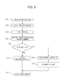
- FIG. 3 is a flowchart of control according to a second embodiment.
- FIG. 4 is a sectional view of a main part of an image forming apparatus according to a third embodiment.
- FIG. 5 is a flowchart of control according to the third embodiment.
- FIG. 6 is a sectional view of a main part of an image forming apparatus according to fourth and sixth embodiments.
- FIG. 7 is a block diagram of main functions of the image forming apparatus according to the fourth and sixth embodiments.
- FIGS. 8A to 80 are timing charts of signals according to the fourth embodiment.
- FIG. 9 is a flowchart of control according to the fourth and sixth embodiments.
- FIG. 10 is a flowchart of control according to the fourth and sixth embodiments.
- FIG. 11 is a sectional view of a main part of an image forming apparatus according to a fifth embodiment.
- FIG. 12 is a block diagram of main functions of the image forming apparatus according to the fifth embodiment.
- FIG. 13 is a flowchart of control according to the fifth embodiment.
- FIG. 14 is a flowchart of control according to the fifth embodiment.
- FIG. 15 is a cleaning time determination table according to the sixth embodiment.
- FIG. 1 is a cross sectional view schematically illustrating a configuration of an image forming apparatus according to the first embodiment.
- the image forming apparatus of this embodiment is a laser printer employing a transfer method utilizing an electrophotographic process.
- a determination as to whether a cleaning sequence is to be performed in accordance with a downtime of the image forming apparatus is made.
- the downtime of the image forming apparatus is a period of time measured by a control unit (a controller) described below, that is, a period of time from when a certain printing operation (an image forming operation) is terminated to when a next printing operation (an image forming operation) is started.
- the image forming apparatus includes a photosensitive member 1 having a drum shape (hereinafter referred to as a “photosensitive drum”) as an image bearing member.
- the photosensitive drum 1 includes a conductive base layer 1 b formed of aluminum, iron, or the like and a photoconductive layer 1 a formed of an organic photoconductive body, for example, disposed on an outer peripheral surface of the conductive base layer 1 b as a base configuration layer and is driven to rotate in a direction indicated by an arrow mark X (a clockwise direction) in a certain circumferential velocity (a certain process speed). Note that the conductive base layer 1 b is grounded.
- the photosensitive drum 1 is uniformly subjected to a charge process so as to have a predetermined polarity and a predetermined potential (Vd) by a first charge apparatus (hereinafter referred to as a “charge roller”) serving as a charger while the photosensitive drum 1 rotates.
- the charge roller 2 of this embodiment is a contact charge roller.
- the charge roller 2 includes a conductive roller 2 c , such as a metallic roller serving as core metal, a conductive layer 2 b formed on an outer peripheral surface of the conductive roller 2 c , and a resistance layer 2 a further formed on an outer peripheral surface of the conductive layer 2 b .
- the charge roller 2 includes the conductive roller 2 c having opposite ends supported by a bearing member (not illustrated) to be rotated, is disposed in parallel to the photosensitive drum 1 , and is pressed toward the photosensitive drum 1 by a pressing unit, such as a spring not illustrated, with a predetermined pressing force so as to be in contact with the photosensitive drum 1 .
- the charge roller 2 is rotated when the conductive roller 2 c is forcibly driven by a driving unit, not illustrated.
- a predetermined bias voltage (a direct current voltage or an oscillation voltage) is applied from a power source 3 through an electric contact to the conductive roller 2 c so that a peripheral surface of the photosensitive drum 1 is uniformly subjected to the charge process in a contact charge method so as to have a predetermined polarity and a predetermined potential.
- an image exposure unit 5 such as a laser scanner slit exposure unit, performs an image exposure process (an exposure L) using target image information on a surface of the photosensitive drum 1 to be subjected to the charge process so that electrostatic latent image of the target image information is formed on the surface of the photosensitive drum 1 .
- an image exposure process an exposure L
- V 1 a potential of the exposed photosensitive drum 1
- the electrostatic latent image is developed using a developing agent (toner) supported by a developing sleeve 6 a of a developing apparatus (a developing unit) 6 as a thin layer so that a visible image (a toner image) is obtained.
- the toner image is supplied from a feeding unit side to a transfer portion N at a predetermined timing and is successively transferred to transfer members conveyed along a conveying path 20 .
- a transfer roller (a transfer unit) 7 includes a conductive roller 7 a , such as a metallic roller serving as a core metal, and a cylindrical conductive layer 7 b formed on an outer peripheral surface of the conductive roller 7 a .
- the transfer roller 7 includes the conductive roller 7 a having opposite ends supported by a bearing member, not illustrated, in a rotatable manner, is arranged in parallel to the photosensitive drum 1 , and is pressed toward the photosensitive drum 1 by a pressing unit, such as a spring not illustrated, so as to contact with the photosensitive drum 1 .
- the transfer roller 7 rotates in accordance with rotation of the photosensitive drum 1 .
- a contact nip portion between the photosensitive drum 1 and the transfer roller 7 corresponds to the transfer portion N.
- a transfer member 9 is supplied from a sheet tray T using a feeding roller 14 , conveyed by conveying rollers 15 a and 15 b , and supplied to the transfer portion N through a pre-transfer guide 11 .
- a power source 4 supplies a predetermined transfer bias voltage to the conductive roller 7 a , a back surface of the transfer member 9 which is in contact with the transfer roller 7 is charged in a contact charge method so as to have a polarity opposite to that of the toner, and accordingly, a toner image on the photosensitive drum 1 is transferred on a surface of the transfer member 9 .
- the transfer member 9 having the toner image transferred thereto when the transfer member 9 passes the transfer portion N is separated from the surface of the photosensitive drum 1 before being supplied to an image fixing unit 12 where the transfer toner image is fixed on the transfer member 9 as a permanently-fixed image.
- a period of time required for starting operation and finishing operation of the image forming apparatus is approximately 10 seconds, and a period of time required for image formation is approximately 10 seconds per one transfer member 9 . Specifically, approximately 20 seconds is required for a print job for a single transfer member 9 , and approximately 30 seconds is required for a print job for two transfer members 9 .
- a controller 13 performs operation control in the image forming process, and in addition, performs time counting, that is, the controller 13 may measure a downtime or the like.
- the controller 13 serving as a control unit measures a downtime of the image forming apparatus.
- an example of a carrying member which has a carrying surface for carrying the transfer members 9 which is exposed out of the image forming apparatus is the sheet tray T. Therefore, when the transfer member 9 is set in the sheet tray T, a portion of the carrying surface for carrying the transfer members 9 (a region d in FIG. 1 ) is exposed out of the image forming apparatus and dust may be deposited on the exposed portion.
- a life duration of the developing apparatus 6 is determined in accordance with a rotation time (a rotation speed) of the developing sleeve 6 a , and a life duration of the developing sleeve 6 a in this embodiment is approximately 40000 seconds.
- a rotation time a rotation speed
- a life duration of the developing sleeve 6 a in this embodiment is approximately 40000 seconds.
- a toner is negatively charged in the developing apparatus 6 .
- the charge roller 2 uniformly performs a charge process on the surface of the photosensitive drum 1 using a negative bias having a polarity the same as that of the toner, and the image exposure unit 5 performs image exposure.
- a positive bias having an opposite polarity is applied to the transfer portion N and a toner image is transferred from the photosensitive drum 1 to a sheet (the transfer member 9 ).
- a voltage of ⁇ 1000 V is applied to the charge roller 2 , a voltage of ⁇ 500 V is applied to the surface of the photosensitive drum 1 , and laser exposure is performed so that the image exposure portion has a voltage of ⁇ 150 V.
- the controller 13 causes the power source, not illustrated, to apply a voltage of ⁇ 350 V to the developing apparatus 6 , and a potential difference (Vback) between the developing sleeve 6 a and the surface of the photosensitive drum 1 is 150 V.
- a cleaning sequence (a cleaning operation) for cleaning the surface of the photosensitive drum 1 performed by the developing apparatus 6 so that dust which is not collected to the development concurrent cleaning is collected is performed.
- the potential difference Vback is increased when compared with the development concurrent cleaning resulting in enhanced performance of development collection so that collection of dust is facilitated.
- a voltage of ⁇ 1200 V is applied to the charge roller and a voltage of ⁇ 700 V is charged to the surface of the photosensitive drum 1 . Furthermore, a voltage of ⁇ 350 V is applied to the developing apparatus. Therefore, the potential difference Vback at the time of the cleaning sequence is 350 V which is larger than that in the development concurrent cleaning.
- dust attached to a certain position of the photosensitive drum 1 is charged every rotation of the photosensitive drum 1 and subjected to the cleaning operation of the development collection. For example, if the dust may not be charged to a degree that the development collection is available in a first charge process, a charge amount is increased so that the development collection becomes available by repeatedly performing the charge process in second and third rotations and so on. Specifically, an effect of the cleaning sequence is changed depending on a period of time in which the cleaning sequence is performed. That is, the longer the period of time is, the higher the cleaning effect is.
- the photosensitive drum 1 has a diameter of 24 mm and is driven to rotate at a speed of 150 mm/sec in the direction denoted by the arrow mark X. Therefore, in the cleaning sequence, the cleaning is performed for approximately two rotations of the photosensitive drum 1 per one second.
- the cleaning sequence in this embodiment is performed for approximately 10.5 seconds. Note that a period of time required for rising and falling of a voltage of the charge roller and the developing apparatus 6 in the cleaning sequence is approximately 0.5 seconds, and the cleaning effect is obtained at maximum for approximately 10 seconds (20 rotations of the photosensitive drum 1 ).
- the cleaning sequence is not performed every after a print job is performed, but the cleaning sequence is preferably performed only when an image defect, such as white spots or black spots, is generated due to dust which has not been collected by the development concurrent cleaning.
- a part of the dust may not be collected by the development collection. Specifically, a determination as to whether the cleaning sequence is to be performed is made depending on an amount of dust attached on the photosensitive drum 1 .
- This embodiment employs a method for estimating an amount of dust deposited on the transfer member 9 with reference to a downtime (a period of time between print jobs) of the image forming apparatus. For example, if a period of time from a time point when a certain printing operation is terminated to a time point when a next print job is started (the downtime) is long in a state in which the transfer member 9 is set on the sheet tray T, dust is deposited on the transfer member 9 (the region d in FIG. 1 ). Here, the amount of dust on the transfer member 9 is increased as the downtime is increased.
- the cleaning sequence is performed when the downtime is equal to or longer than a predetermined period of time (18 hours in this embodiment).
- a user supplies a print start job to a printer (S 11 ).
- Image size information as print information is supplied to the controller 13 of FIG. 1 (S 12 ), the printer starts a print sequence (S 13 ), and the printer performs image formation on the transfer member 9 (S 14 ).
- the controller 13 checks a downtime after termination of a preceding printing operation (S 15 ).
- the printing operation is terminated (S 16 ). In this case, although the printing is terminated, the cleaning sequence is not performed, and then, a waiting state is entered (S 17 ). On the other hand, in a case where the downtime is equal to or longer than 18 hours (longer than the predetermined period of time), the printing operation is terminated (S 18 ). Thereafter, the cleaning sequence is performed (S 19 ). After the cleaning sequence is performed, the printing is terminated and the waiting state is entered (S 17 ).
- an image defect is checked both in a case where the cleaning sequence is not performed in image forming apparatuses having the transfer member 9 on which dust is deposited during the predetermined downtimes and a case where the cleaning sequence of this embodiment is performed in the image forming apparatuses.
- Dust exists solid white: Dust is transferred to the photosensitive drum 1 .
- Dust does not exist solid white: Generated black spots are counted.
- Dust does not exist HT: Generated white spots are counted.
- Dust exists solid white: Dust is transferred to the photosensitive drum 1 .
- Cleaning Operation Development collection is performed on the dust on the photosensitive drum 1 .
- Dust does not exist solid white: Generated black spots are counted.
- Dust does not exist HT: Generated white spots are counted.
- the transfer member 9 (LTR paper, grammage 75 g/m2) is left on the sheet tray T for a predetermined period of time, printing is performed in a state in which dust is deposited on the transfer member 9 (a solid white image), and the dust is transferred to the photosensitive drum 1 . Subsequently, the solid white image is printed using a new transfer member 9 which does not have dust attached thereon and generated black spots are counted. Similarly, an HT image is printed after the left transfer member 9 is printed, and thereafter, generated white spots are counted.
- Table 1 illustrates sums of the numbers of generated black spots and white spots under the various conditions.
- the cleaning sequence is not performed, if a downtime is equal to or larger than 24 hours, an image defect occurs. On the other hand, in the case where the cleaning sequence of this embodiment is performed, an image defect does not occur even when a downtime is 48 hours. Therefore, it is preferable that the cleaning sequence is not performed when the downtime is shorter than 18 hours (shorter than the predetermined period of time) in this embodiment and the cleaning sequence is performed when the downtime is equal to or longer than 18 hours.
- the number of sheets which are printable by development life duration in a case where the cleaning sequence is performed for each print job which is a comparison example
- the number of sheets which are printable by the development life duration in a case where the cleaning sequence is performed when the downtime of this embodiment becomes equal to or longer than 18 hours are compared with each other.
- the cleaning sequence is performed when the downtime of this embodiment is equal to or longer than 18 hours, the cleaning sequence is performed only for a first print job in a day at most. It is assume that the cleaning sequence is performed by all means when a first print job for a day is performed in this embodiment.
- a cleaning operation time of this embodiment is shorter than a cleaning operation time obtained in the case where the cleaning sequence is performed for each print job which is the comparative example. Therefore, the number of sheets which are printable by the time when 40000 seconds which is the life duration (a rotation time) of the developing sleeve 6 a is reached is larger than the comparative example. Specifically, 1974 sheets are printable in the comparative example, whereas 2448 sheets are printable in this embodiment.
- a period of time the cleaning is performed is 10.5 seconds in the cleaning sequence of this embodiment, the present technique is not limited to this and the period of time the cleaning is performed may be changed depending on a use condition of the image forming apparatus.
- a determination as to whether the cleaning sequence is to be performed is made depending on the downtime (the amount of dust) in the first embodiment, a period of time a cleaning sequence (a cleaning operation) is performed is changed in accordance with a downtime in this embodiment.
- the verification is made until the case where the downtime is 48 hours.
- the downtime is 48 hours.
- an amount of dust on a transfer member 9 is further increased, and therefore, occurrence of an image defect may not be suppressed even if the cleaning sequence of the first embodiment is performed.
- dust collection performance is improved by extending a period of time the cleaning sequence is performed, so that occurrence of an image defect is suppressed.
- the period of time the cleaning sequence is performed is longer, a dust collection effect is higher.
- the period of time the cleaning sequence is to be performed is preferably determined in accordance with an amount of dust in terms of a life duration of the apparatus and delay of a next print job.
- a cleaning effect may be enhanced by increasing the period of time the cleaning sequence is performed.
- one of two cleaning sequences that is, the cleaning sequence performed in a first performance time (approximately 10.5 seconds in the first embodiment) and a cleaning sequence performed in a second performance time (approximately 20.5 seconds) is selectively used in accordance with a downtime.
- a period of time required for rising and falling of a voltage of a charge roller 2 and a developing apparatus 6 in the cleaning sequence is approximately 0.5 seconds, and the cleaning effect is obtained at maximum for approximately 10 seconds (for 20 rotations of the photosensitive drum 1 ) in a case where the cleaning sequence is performed for 10.5 seconds.
- a user supplies a print start job to a printer (S 21 ).
- Image size information as print information is supplied to a controller 13 of FIG. 1 (S 22 ), the printer starts a print sequence (S 23 ), and the printer performs image formation on the transfer member 9 (S 24 ).
- the controller 13 checks a downtime after termination of a preceding printing operation (S 25 ).
- the printing operation is terminated (S 26 ). In this case, although the printing is terminated, the cleaning sequence is not performed, and thereafter, a waiting state is entered (S 27 ).
- the printing operation is terminated (S 28 ) and the first cleaning sequence is performed (S 29 ). In the first cleaning sequence, the cleaning sequence of the first performance time is performed. Then the printing is terminated and a waiting state is entered (S 27 ).
- the printing operation is terminated (S 30 ) and the second cleaning sequence is performed (S 31 ). In the second cleaning sequence, the cleaning sequence of the second performance time which is longer than the first performance time is performed. Then the printing is terminated and a waiting state is entered (S 27 ).
- the present technique is not limited to this.
- the predetermined time to be compared with a downtime is to be appropriately set for each apparatus in accordance with an amount of dust deposited on a left recording member or the like.
- a checking method presence and absence of an image defect is checked in a case where the cleaning sequence is not performed on image forming apparatuses having the transfer member 9 on which dust is deposited during the predetermined downtimes, a case where the cleaning sequence of the first performance time (10.5 seconds here) is performed, and a case where the cleaning sequence of the second performance time (20.5 seconds here) is performed.
- the transfer member 9 In a general office, an environment in which temperature is 23° C. and humidity is 50% is set, the transfer member 9 (LTR paper, grammage 75 g/m2) is left on the sheet tray T for a predetermined period of time, printing is performed in a state in which dust is deposited on the transfer member 9 (a solid white image), and the dust is transferred to the photosensitive drum 1 . Subsequently, the solid white image is printed on a new transfer member 9 which does not have dust attached thereon and generated black spots are counted. Similarly, an HT image is printed after the left transfer member 9 is printed, and thereafter, generated white spots are counted.
- Table 3 illustrates sums of generated black spots and white spots under the various conditions.
- the cleaning sequence when a downtime is equal to or longer than 24 hours, an image defect occurs. Furthermore, in the case where the cleaning sequence is performed for 10.5 seconds, when the downtime is equal to or longer than 72 hours, an image defect occurs. On the other hand, in the case where the cleaning sequence is performed for 20.5 seconds, an image defect does not occur even when a downtime is 120 hours. Accordingly, it is preferable that the cleaning sequence is performed for 10.5 seconds (the first performance time) when the downtime is equal to or longer than 18 hours and shorter than 48 hours, whereas the cleaning sequence is performed for 20.5 seconds (the second performance time) when the downtime is equal to or longer than 48 hours and shorter than 120 hours.
- the number of sheets which are printable by a development life duration in a case where the cleaning sequence is performed for each print job which is a comparison example
- the number of sheets which are printable by the development life duration in a case where the cleaning sequence is performed for 10. 5 seconds when the downtime of this embodiment is equal to or longer than 18 hours and shorter than 48 hours and the cleaning sequence is performed for 20.5 seconds when the downtime is equal to or longer than 48 hours and shorter than 120 hours are compared with each other.
- the cleaning sequence is performed for 20.5 seconds. Furthermore, it is expected that a downtime becomes equal to or longer than 18 hours only once at most, that is, in a first print job, in a day on Tuesday, Wednesday, Thursday, and Friday. In this embodiment, the cleaning sequence is performed for 10.5 seconds when the first print job in a day is performed on Tuesday, Wednesday, Thursday, and Friday.
- a cleaning operation time of this embodiment is shorter than a cleaning operation time obtained in the case where the cleaning sequence is performed for each print job which is the comparative example. Therefore, the number of sheets which are printable by the time when 40000 seconds which is life duration (a rotation time) of a developing sleeve 6 a is reached is larger than the comparative example. Specifically, 1584 sheets are printable in the comparative example, whereas 2400 sheets are printable in this embodiment.
- the cleaning sequence is performed at an appropriate timing for an appropriate period of time in accordance with a downtime (an amount of dust) so that an optimum rotation speed of the developing sleeve 6 a is attained.
- a downtime an amount of dust
- a period of time the cleaning is performed is 10.5 seconds or 20.5 seconds in the cleaning sequence of this embodiment
- the present technique is not limited to this and the period of time the cleaning is performed may be changed depending on a use condition of the image forming apparatus. For example, when a downtime is longer than 120 hours which is included in effect verification in this embodiment or when the apparatus is used under an environment in which an amount of dust deposited on the transfer member 9 is large, occurrence of an image defect may be further suppressed by a longer performance time of the cleaning sequence.
- FIG. 4 is a cross sectional view schematically illustrating a configuration of the image forming apparatus according to the third embodiment.
- the image forming apparatus of this embodiment includes a plurality of carrying members which carry transfer members 9 .
- a sheet tray T is illustrated as a first carrying member and a multi-size tray M is illustrated as a second carrying member.
- the transfer members 9 are accommodated in the image forming apparatus when being set on the sheet tray T, and therefore, dust is barely deposited on the transfer members 9 .
- a size of the transfer members 9 which are settable in the sheet tray T is restricted, and transfer members 9 of sizes larger the sheet tray T are not accommodated in the image forming apparatus. Therefore, the multi-size tray M is used for transfer members 9 of a large size.
- the sheet tray T is used for sheets of an A4 size and an LTR size
- the multi-size tray M is used for larger transfer members 9 .
- a feeding roller 16 is used. Thereafter the transfer member 9 is conveyed by conveying rollers 15 a and 15 b , and a subsequent process is the same as that performed when the sheet tray T is used.
- a determination as to whether the sheet tray T or the multi-size tray M is used for sheet feeding is made under control of a controller 13 in accordance with a user's instruction.
- the controller 13 performs operation control in the image forming process, and in addition, performs time counting, and therefore, the controller 13 may measure a feeding time or the like.
- a portion of the transfer member 9 may be exposed out of the image forming apparatus. In this case, dust is deposited on the portion. If printing is performed while dust is attached on the transfer member 9 , the dust may be attached on a photosensitive drum 1 . If image formation is performed in a state in which dust is attached on the photosensitive drum 1 , charging failure or developing failure may occur resulting in an image defect.
- a cleaning sequence is performed when the multi-size tray M having a carrying surface for transfer members which is exposed out of the apparatus is used so that occurrence of an image defect is suppressed.
- the cleaning sequence As a condition for an operation of the cleaning sequence, when an interval of sheet feeding from the multi-size tray M exceeds a predetermined period of time, the cleaning sequence is performed after a next printing operation. Content of the operation of the cleaning sequence is the same as those described in the first and second embodiments. Note that the interval of sheet feeding from the multi-size tray M corresponds to a period of time from when a certain feeding operation is terminated to when a next feeding operation is performed.
- one of the feeding ports to be subjected to the cleaning sequence is selected in accordance with a sheet feeding interval (an amount of dust). In this way, decrease of life duration of the apparatus and delay of a next print job may be suppressed while occurrence of an image defect is suppressed.
- a user supplies a print start job to a printer (S 41 ).
- Image size information as print information is supplied to the controller 13 of FIG. 1 (S 42 ), the printer starts a print sequence (S 43 ), and the printer performs image formation on the transfer member 9 (S 44 ).
- the controller 13 determines one of the sheet tray T and the multi-size tray M which has supplied the transfer member 9 (S 45 ).
- the printing operation is terminated (S 46 ). In this case, although the printing is terminated, the cleaning sequence is not performed, and a waiting state is entered (S 47 ).
- the controller 13 determines whether a feeding time (a feeding interval or a downtime) exceeds a predetermined period of time (S 48 ). When the determination is negative, the printing operation is terminated (S 46 ). In this case, although the printing is terminated, the cleaning sequence is not performed, and a waiting state is entered (S 47 ). On the other hand, when the determination is affirmative, the printing operation is terminated (S 49 ). Thereafter, the cleaning sequence is performed (S 50 ). After the cleaning sequence is performed, the printing is terminated and the waiting state is entered (S 47 ).
- a feeding time a feeding interval or a downtime
- the cleaning sequence is performed where appropriate in accordance with the feeding time (the amount of dust).
- a performance time of the cleaning sequence (the cleaning operation) may be changed in accordance with a feeding time (an interval of sheet feeding) from the multi-size tray M also in this embodiment. Also with this configuration, the same effects as the foregoing embodiments may be obtained.
- FIG. 6 is a cross sectional view schematically illustrating a configuration the image forming apparatus according to the fourth embodiment.
- the image forming apparatus of this embodiment is a laser printer employing a transfer method utilizing an electrophotographic process.
- the image forming apparatus includes a photosensitive member (photosensitive drum) 1 having a drum shape as an image bearing member.
- the photosensitive drum 1 includes a conductive base layer 1 b formed of aluminum, iron, or the like and a photoconductive layer 1 a formed of an organic photoconductive body, for example, disposed on an outer peripheral surface of the conductive base layer 1 b as a base configuration layer and is driven to rotate in a direction indicated by an arrow mark X (a clockwise direction) in a certain circumferential velocity (a process speed). Note that the conductive base layer 1 b is grounded.
- the photosensitive drum 1 is uniformly subjected to a charge process performed by a first charge apparatus (charge roller) 2 serving as a charger so as to have a predetermined polarity and a predetermined potential (Vd) while the photosensitive drum 1 rotates.
- the charge roller 2 of this embodiment is a contact charge roller.
- the charge roller 2 includes a conductive roller 2 c , such as a metallic roller serving as core metal, a conductive layer 2 b formed on an outer peripheral surface of the conductive roller 2 c , and a resistance layer 2 a further formed on an outer peripheral surface of the conductive layer 2 b .
- the charge roller 2 includes the conductive roller 2 c having opposite ends supported by a bearing member (not illustrated) to be rotated, is disposed in parallel to the photosensitive drum 1 , and is pressed toward the photosensitive drum 1 by a pressing unit, such as a spring not illustrated, with a predetermined pressing force so as to be in contact with the photosensitive drum 1 .
- the charge roller 2 is rotated when the conductive roller 2 c is forcibly driven by a driving unit, not illustrated.
- a predetermined bias voltage (a direct current voltage or an oscillation voltage) is applied from a power source 3 through an electric contact to the conductive roller 2 c so that a peripheral surface of the photosensitive member 1 is uniformly subjected to the charge process in a contact charge method so as to have a predetermined polarity and a predetermined potential.
- an image exposure unit 5 such as a laser scanner slit exposure unit, performs an image exposure process (an exposure L) using target image information on a surface of the photosensitive drum 1 to be subjected to the charge process so that an electrostatic latent image of the target image information is formed on the surface of the photosensitive drum 1 .
- an image exposure process an exposure L
- V 1 a potential of the exposed photosensitive member 1
- the electrostatic latent image is developed using a developing agent (toner) supported by a developing sleeve 6 a of a developing apparatus (a developing unit) 6 as a thin layer so that a visible image (a toner image) is obtained.
- the toner image is supplied from a feeding unit side to a transfer portion N at a predetermined timing and is successively transferred to transfer members conveyed along a conveying path 20 .
- a transfer roller (a transfer unit) 7 of this embodiment serving as a contact charge transfer roller includes a conductive roller 7 a , such as a metallic roller serving as a core metal, and a cylindrical conductive layer 7 b formed on an outer peripheral surface of the conductive roller 7 a .
- the transfer roller 7 includes the conductive roller 7 a having opposite ends supported by a bearing member, not illustrated, in a rotatable manner, is arranged in parallel to the photosensitive drum 1 , and is pressed toward the photosensitive drum 1 by a pressing unit, such as a spring not illustrated, so as to contact with the photosensitive drum 1 .
- the transfer roller 7 rotates in accordance with rotation of the photosensitive drum 1 .
- a contact nip portion between the photosensitive member 1 and the transfer roller 7 corresponds to the transfer portion N.
- a transfer member 9 is supplied from a sheet tray T using a feeding roller 14 , conveyed by conveying rollers 15 a and 15 b , and supplied to the transfer portion N through a pre-transfer guide 11 .
- a power source 4 supplies a predetermined transfer bias voltage to the conductive roller 7 a , a back surface of a transfer member which is in contact with the transfer roller 7 is charged in a contact charge method so as to have a polarity opposite to that of the toner, and accordingly, a toner image on the photosensitive drum 1 is transferred on a surface of the transfer member 9 .
- the transfer member 9 having the toner image transferred thereto when the transfer member 9 passes the transfer portion N is separated from the surface of the photosensitive member 1 before being supplied to an image fixing unit 12 , and the transfer toner image is fixed on the transfer member 9 as permanently-fixed image.
- the controller 13 performs operation control in the image forming process described above.
- toner is negatively charged in the developing apparatus 6 .
- the charge roller 2 uniformly performs a charge process on the surface of the photosensitive drum 1 using a negative bias having a polarity the same as that of the toner.
- a positive bias having an opposite polarity is applied to the transfer portion N and a toner image is transferred from the photosensitive drum 1 to a sheet (the transfer member 9 ).
- a voltage of ⁇ 1000 V is applied to the charge roller 2 , a voltage of ⁇ 500 V is applied to the surface of the photosensitive drum 1 , and laser exposure is performed so that the image exposure portion performs has a voltage of ⁇ 150 V. Furthermore, the controller 13 causes the power source, not illustrated, to apply a voltage of ⁇ 350 V on the developing apparatus 6 , and a potential difference (Vback) between the developing sleeve 6 a and the photosensitive drum 1 is 150 V.
- Residual transfer toner is charged by the charge roller 2 to have a negative polarity and collected by the developing apparatus 6 from the photosensitive drum 1 by the potential difference Vback.
- the dust attached on the photosensitive drum 1 is also charged by the charge roller 2 , as with the residual transfer toner, to have a negative polarity and is collected by the developing apparatus 6 .
- the dust may not be collected if a size, a shape, or material of the dust is not sufficient for the negative charging or if a charge amount is small.
- developing failure or charging failure occurs in the portion on the photosensitive drum 1 to which the dust is attached resulting in an image defect.
- a bias to be applied to the charge roller 2 is increased, for example. If a bias to be applied to the charge roller 2 is increased, the dust is negatively charged with ease, and a surface potential of the photosensitive drum 1 is increased so that a potential difference Vback is increased and collection property of the developing apparatus may be improved.
- conversion fogging is a phenomenon in which a polarity of toner which has been negatively charged by the developing apparatus 6 is reversed due to a potential difference between the surface potential of the photosensitive drum 1 and a potential of the developing apparatus 6 , that is, the toner has a positive polarity, and therefore, the toner is transferred from the developing apparatus 6 to a portion of the photosensitive drum 1 which is not subjected to the image exposure.
- the toner which is subjected to the inversion fogging has the positive polarity, and therefore, the toner is not electrostatically transferred on the transfer member 9 . However, a part of the toner is transferred on the transfer member 9 , and accordingly, image defect may occur.
- an image defect which is referred to as “white spots” is generated in an image forming portion on the transfer member 9
- an image defect which is referred to as “black spots” is generated in a non-image portion on the transfer member 9 .
- the white spots are white blanks in an image to be black generated when toner is not developed in a dust portion if dust is attached to an image exposure portion on the photosensitive drum 1 .
- the black spots are generated when the charging failure occurs in a dust attachment portion on a surface of the photosensitive drum 1 , a potential of the portion becomes higher than that of the developing apparatus, and accordingly, toner is transferred from the developing apparatus 6 even in a non-image portion and appears as black spots on the transfer member 9 .
- a cleaning sequence for increasing a bias to be applied to the charge roller 2 in the non-image formation when compared with a bias in the image formation so as to perform development collection on dust which has not been collected by the development concurrent cleaning is performed.
- the cleaning sequence is performed, the development collection may be performed on the dust which remains in the photosensitive drum 1 and an image defect including black spots and white spots may be suppressed.
- a voltage of ⁇ 1200 V is applied to the charge roller 2 , a voltage of ⁇ 700 V is charged to the surface of the photosensitive drum 1 , exposure is performed so that the image exposure portion has a voltage of ⁇ 150 V, and a voltage of ⁇ 350 V is applied to the developing apparatus 6 .
- the potential difference Vback at the time of the cleaning sequence is 350 V which is larger than that in the development concurrent cleaning.
- a performance time for one cleaning sequence is approximately 7 seconds.
- FIG. 7 is a block diagram of main functions of the image forming apparatus according to the fourth embodiment.
- a CPU 201 controls the image forming apparatus.
- the controller 13 of FIG. 1 includes the CPU 201 , a timer 203 for sheet presence elapsed time, and a timer 204 for feeding elapsed time which are illustrated in FIG. 2 .
- a sheet sensor 21 is a detection unit which detects the transfer member 9 on the sheet tray T and outputs a result of a determination as to whether the transfer member 9 is placed on the sheet tray T to the CPU 201 .
- the timer 203 for sheet presence elapsed time is a second time measurement unit which measures a period of time after the sheet sensor 21 detects a sheet, that is, the timer 203 for sheet presence elapsed time measures a period of time in which the sheet sensor 21 detects a sheet.
- the timer 203 for sheet presence elapsed time indicates 0 while the sheet sensor 21 does not detect a sheet whereas the timer 203 for sheet presence elapsed time indicates t 1 when a measurement time representing that a sheet exists is equal to or larger than a predetermined period of time t 1 .
- the predetermined period of time t 1 is experimentally obtained taking an amount of dust deposited on the transfer member 9 on the sheet tray T into consideration, and an image defect is seen not to occur by an amount of deposition of dust within the predetermined period of time t 1 .
- the predetermined period of time t 1 is 18 hours in this embodiment.
- a feeding solenoid 205 is driven by a feeding driving signal supplied from the CPU 201 . When the feeding solenoid 205 is driven, the feeding roller 14 starts an operation of selecting one of the transfer members 9 on the sheet tray T and supplying the transfer member 9 into the image forming apparatus.
- the timer 204 for feeding elapsed time is a first measurement unit which measures a time of the image forming operation and measures a period of time after the CPU 201 outputs the feeding driving signal in this embodiment.
- the timer 204 for feeding elapsed time outputs t 1 .
- a conveying motor 206 is driven by a driving signal supplied from the CPU 201 and serves as a driving source for rotating rollers, such as the conveying rollers 15 a and 15 b illustrated in FIG. 6 .
- a high-voltage power source 207 includes a power source (not illustrated) which outputs a high voltage to be supplied to the power source 3 , the power source 4 , and the developing sleeve 6 a illustrated in FIG. 6 in accordance with a high-voltage driving signal supplied from the CPU 201 .
- FIGS. 8A to 8C are diagrams illustrating the relationships among the feeding solenoid driving signal, the timer 204 for feeding elapsed time, a detection state of the sheet sensor 21 , the timer 203 for sheet presence elapsed time, and permission/prohibition of the cleaning sequence.
- the CPU 201 included in the controller 13 serving as a control unit controls an operation described below in accordance with times measured by the timer 203 for sheet presence elapsed time and the timer 204 for feeding elapsed time.
- FIGS. 8A to 8C certain printing is instructed at a timing A. It is assumed here that the timer 204 for feeding elapsed time indicates a time shorter than the predetermined period of time t 1 . Since the feeding elapsed time is shorter than t 1 , and the cleaning sequence is not permitted.
- a timing B sheet feeding is instructed in response to a printing instruction issued at the timing A.
- the sheet tray T runs out of the transfer member 9 , and therefore, the sheet sensor 21 does not detect the transfer member 9 .
- a transfer member 9 is set on the sheet tray T, and therefore, the sheet sensor 21 detects the transfer member 9 . Note that only the case of FIG. 8A includes a state in which a sheet is not detected, and a sheet is constantly detected in the cases of FIGS. 8B and 8C .
- next printing is instructed.
- sheet feeding is instructed in response to the next printing instruction.
- the cleaning sequence is terminated.
- FIG. 9 is a control flowchart of the CPU 201 performed when printing is instructed.
- a determination for permission of the cleaning sequence is performed (S 401 ).
- a flow of the cleaning permission determination is illustrated in FIG. 10 , and determinations performed by the CPU 201 at the timing E in the various cases of FIGS. 8A to 8C are described.
- the timer 204 for feeding elapsed time is referred to as a “feeding timer”
- the timer 203 for sheet presence elapsed time is referred to as a “sheet presence timer”.
- the timer 204 for feeding elapsed time indicates the predetermined period of time t 1 (S 411 )
- the timer 203 for sheet presence elapsed time indicates a time shorter than the predetermined period of time t 1 (S 412 ), and therefore, the cleaning is prohibited (S 414 ).
- the cleaning operation of cleaning a surface of the photosensitive drum 1 performed by the developing apparatus 6 is prohibited.
- FIG. 8A since a smaller one of the measurement times measured by the timer 204 for feeding elapsed time and the timer 203 for sheet presence elapsed time is shorter than the predetermined period of time t 1 , the cleaning operation of cleaning a surface of the photosensitive drum 1 performed by the developing apparatus 6 is prohibited.
- the cleaning is permitted (S 413 ). Specifically, since a smaller one of the measurement times measured by the timer 204 for feeding elapsed time and the timer 203 for sheet presence elapsed time is equal to or longer than the predetermined period of time t 1 , the cleaning operation is permitted.
- the cleaning is prohibited (S 414 ). Specifically, since a smaller one of the measurement times measured by the timer 204 for feeding elapsed time and the timer 203 for sheet presence elapsed time is shorter than the predetermined period of time t 1 , the cleaning operation is prohibited.
- the CPU 201 instructs feeding of the transfer member 9 and performs image formation (S 402 ). After the image formation is performed on a first transfer member 9 , the CPU 201 determines whether the cleaning is permitted (S 403 ). When the determination is affirmative, the cleaning sequence is performed (S 404 ), and thereafter, the cleaning is prohibited (S 405 ). On the other hand, when the determination is negative in step S 403 , the cleaning sequence is not performed. At this time point, it is determined whether an instruction for next printing has been issued. When the determination is negative, the printing operation is terminated, and otherwise, supply of a next transfer member 9 (a second transfer member 9 onwards) is started (S 406 ).
- the predetermined period of time t 1 is 18 hours in this embodiment taking an amount of dust deposited on the transfer member 9 into consideration, the present invention is not limited to this.
- An appropriate value is to be set to the predetermined period of time t 1 depending on a type of the apparatus taking a configuration of the sheet tray T and an exposure area of the transfer member 9 set on the sheet tray T into consideration.
- the image forming apparatus may perform the cleaning sequence in appropriate frequency, waste of time caused by performance of an unrequired cleaning sequence may be reduced and occurrence of an image defect, in particular, white spots or black spots, may be reduced.
- FIG. 11 is a cross sectional view of a main portion of the image forming apparatus according to the fifth embodiment
- FIG. 12 is a block diagram of main functions of the image forming apparatus according to the fifth embodiment. Note that functions the same as those of the fourth embodiment are denoted by reference numerals the same as those in FIGS. 6 and 7 , and descriptions thereof are omitted.
- the image forming apparatus has a plurality of carrying members which carry transfer members 9 .
- a sheet tray T is illustrated as a first carrying member and a multi-size tray M is illustrated as a second carrying member.
- each of the carrying members includes a timer for feeding elapsed time (a first time measurement unit), a timer for sheet presence elapsed time (a second time measurement unit), and a sheet sensor (a detection unit).
- a multi-size tray M may hold (carry) a small number of transfer members 9 separately from the sheet tray T.
- One of the trays to be used is instructed when a printing instruction is issued.
- a CPU 201 When the multi-size tray M is selected, a CPU 201 outputs a driving signal to a feeding solenoid 605 , and when the sheet tray T is selected, the CPU 201 outputs a driving signal to the feeding solenoid 205 so that the transfer member 9 is supplied from the selected tray using a feeding roller. Then the CPU 201 measures periods of time using the timer for feeding elapsed time (the first time measurement unit) and the timer for sheet presence elapsed time (the second time measurement unit) which correspond to the selected one of the trays.
- a sheet sensor 24 is a detection unit which detects the transfer member 9 on the multi-size tray M and outputs a result of a determination as to whether the transfer member 9 is placed on the multi-size tray M to the CPU 201 .
- a registration sensor 22 is disposed on an upstream side in a conveying direction of the transfer member 9 relative to a photosensitive drum 1 on a conveying path 20 and outputs a result of a determination as to whether the transfer member 9 exists in a position of the registration sensor 22 .
- the timer 602 for sheet presence elapsed time is the second time measurement unit which measures a period of time after the sheet sensor 24 detects a sheet, that is, the timer 602 for sheet presence elapsed time measures a period of time in which the sheet sensor 24 maintains a sheet presence state.
- the timer 602 for sheet presence elapsed time indicates 0 while the sheet sensor 24 does not detect a sheet whereas the timer 602 for sheet presence elapsed time indicates t 3 when a measurement time representing the sheet presence state is equal to or larger than a predetermined period of time t 3 .
- the predetermined period of time t 3 is experimentally obtained taking an amount of dust deposited on the transfer member 9 on the multi-size tray M into consideration, and an image defect is seen not to occur by an amount of deposition of dust within the predetermined period of time t 3 .
- the predetermined period of time t 3 is 18 hours in this embodiment.
- a feeding solenoid 605 is driven by a feeding driving signal supplied from the CPU 201 . When the feeding solenoid 605 is driven, the feeding roller 16 starts an operation of selecting one of the transfer members 9 on the multi-size tray M and supplying the transfer member 9 into the image forming apparatus.
- a timer 603 for feeding elapsed time measures a period of time after the transfer member 9 is supplied and reaches the registration sensor 22 in the printing operation instructed to use the sheet tray T.
- the timer 603 for feeding elapsed time is cleared when the transfer member 9 is supplied and reaches the registration sensor 22 , and when the period of time is equal to or longer than t 2 , the timer 603 for feeding elapsed time indicates t 2 .
- the predetermined period of time t 2 is experimentally obtained taking an amount of dust deposited on the transfer member 9 on the sheet tray T into consideration, and an image defect is seen not to occur by an amount of deposition of dust within the predetermined period of time t 2 .
- the predetermined period of time t 2 is 18 hours in this embodiment.
- a timer 604 for feeding elapsed time (a first time measurement unit) measures a period of time after the transfer member 9 is supplied and reaches the registration sensor 22 in the printing operation instructed to use the multi-size tray M. The timer 604 for feeding elapsed time is cleared when the transfer member 9 is supplied and reaches the registration sensor 22 , and when the period of time is equal to or longer than t 2 , the timer 604 for feeding elapsed time indicates t 2 .
- a double-sided solenoid 606 is driven in accordance with a double-sided solenoid driving signal output from the CPU 201 .
- a discharge roller 18 is reversed, a switching member 17 is guided in a direction indicated by an arrow mark Y of FIG. 11 , and the transfer member 9 on the conveying path 20 is guided in a direction of a double-sided conveying path 25 .
- a discharge roller 18 and a switching member 17 are reverse operation units which performs reverse of two sides of the transfer member 9 .
- the transfer member 9 which has been guided to the double-sided conveying path 25 is conveyed on a rear side and a lower side of an apparatus body along the double-sided conveying path 25 and joins in the conveying path 20 again immediately before the conveying rollers 15 a and 15 b .
- a surface of the transfer member 9 on the photosensitive drum 1 side which passes a transfer portion N in a first time becomes a surface on the transfer roller 7 side when passing the transfer portion N in a second time, and therefore, double-sided printing is available.
- a double-sided conveying roller 19 rotates such that the transfer member 9 on the double-sided conveying path 25 is conveyed in a forward direction of the double-sided conveying path 25 irrespective of a driving state of the double-sided solenoid 606 .
- FIG. 13 is a control flowchart of the CPU 201 performed when printing is instructed.
- the CPU 201 performs a cleaning permission determination first when receiving a printing instruction.
- the permission determination will be described in detail hereinafter with reference to FIG. 14 .
- a feeding operation is performed from a specified one of the plurality of trays (S 702 ).
- the cleaning is permitted, exposure is prohibited while high-voltage power sources maintain output states the same as that in the image formation, and the conveyance of the transfer member 9 is continued while a latent image is not formed on the photosensitive drum 1 (S 704 ).
- the CPU 201 waits for a state in which a trailing edge of the transfer member 9 passes the registration sensor 22 so that the registration sensor 22 does not detect a sheet (S 705 ).
- the cleaning sequence is started. Specifically, when the cleaning is permitted, the transfer member 9 passes the transfer portion N without performing the image forming operation on a first surface.
- Setting values in the cleaning sequence and high voltages in the image formation are the same as those of the fourth embodiment, and a performance time of the cleaning sequence is approximately 7 seconds. After the cleaning sequence is terminated, the high voltage at the time of image formation is set again.
- the conveyance of the transfer member 9 is continued in parallel to the execution of the cleaning sequence, and the double-sided solenoid 606 is driven when a predetermined period of time has passed after a discharge sensor 23 detects the trailing edge of the transfer member 9 so that the transfer member 9 is conveyed to the double-sided conveying path 25 (S 707 , S 708 , and S 709 ). Thereafter, when a leading edge of the transfer member 9 reaches the registration sensor 22 and the registration sensor 22 detects the sheet (S 710 ), the driving of the double-sided solenoid 606 is stopped (S 711 ).
- step S 712 image formation is performed on the first transfer member 9 (S 712 ).
- step S 713 a process from step S 707 to step S 711 is further performed.
- FIG. 14 is a diagram illustrating the cleaning permission determination in detail. Note that, in FIG. 14 , as with the case of FIG. 10 , the timer 204 for feeding elapsed time is referred to as a “feeding timer”, and the timer 203 for sheet presence elapsed time is referred to as a “sheet presence timer”.
- the CPU 201 determines one of the trays corresponding to the printing instruction (S 730 ). When the printing is to be performed using the sheet tray T, values of the timer 603 for feeding elapsed time and the timer 203 for sheet presence elapsed time are checked (S 731 and s 732 ).
- the predetermined periods of time t 2 and t 3 are 18 hours in this embodiment taking an amount of dust deposited on the transfer member 9 into consideration.
- different values may be preferably set.
- an appropriate value is to be set to the predetermined period of time t 1 depending on a type of the apparatus taking configurations of the trays and an exposure area of the transfer member 9 set on the sheet tray T into consideration.
- the value of the timer 603 for feeding elapsed time is cleared when the transfer member 9 reaches the registration sensor 22 .
- the value of the timer 604 for feeding elapsed time is cleared when the transfer member 9 reaches the registration sensor 22 . Therefore, in consecutive printing performed once, substantially two cleaning operations are performed at most, and further cleaning operations are not performed.
- the cleaning sequence since the cleaning sequence may be performed in appropriate frequency, waste of time caused by performance of an unrequired cleaning sequence may be reduced and occurrence of an image defect, in particular, white spots or black spots, may be reduced in the image forming apparatus. Furthermore, according to this embodiment, the image forming apparatus which reduces a risk that dust attached on a front portion of the transfer member 9 in a conveying direction is attached to the photosensitive drum 1 and the dust causes an image defect in a rear portion of the transfer member 9 may be provided.
- FIG. 15 A cross-sectional view of a main portion of the image forming apparatus and a block diagram of main functions of the image forming apparatus according to the sixth embodiment are the same as those of the fourth embodiment, and therefore, FIGS. 6, 7, 9, and 10 are used and detailed descriptions thereof are omitted.
- FIG. 15 s a table for determining a cleaning time (a performance time) when the CPU 201 determines that the cleaning is permitted in step S 413 of FIG. 10 .
- a determination time tj corresponds to a smaller one of values of the timer 203 for sheet presence elapsed time and the timer 204 for feeding elapsed time, and is not smaller than t 1 since the cleaning permission is determined.
- the cleaning time may not be restricted by a time tolerant to the cleaning sequence or not saturated, and a table in which the cleaning time tc is increased in accordance with increase of the determination time may be employed.
- the cleaning time tc indicates a period of time in which settings of high voltages are set to a predetermined voltage during the cleaning sequence.
- the setting values of the high voltages in the cleaning sequence and in the image formation are the same as those of the fourth embodiment.
- t 1 is 18 hours
- t 4 is 72 hours
- t 5 is 7 seconds
- t 7 is 14 seconds
- the values are not limited to these and appropriate values may be set taking a configuration of the sheet tray T and an exposure area of the transfer member 9 which is set on the sheet tray T into consideration.
- the cleaning sequence may be performed in appropriate frequency for a required period of time. Therefore, an image forming apparatus capable of reducing waste of time caused by an unrequired cleaning sequence and an image defect (in particular, generation of white spots and black spots) may be provided.
- An image forming apparatus may be a copier, a facsimile, or the like or may be multifunction peripheral having these functions combined with each other. The same effect may be obtained by employing the present technique in these image forming apparatuses.
- the present invention is not limited to this.
- the same effect may be obtained when the present invention is employed in a configuration in which a sheet is fed from a tray of a sheet feeding device which is detachably attached to the image forming apparatus.
Landscapes
- Physics & Mathematics (AREA)
- General Physics & Mathematics (AREA)
- Engineering & Computer Science (AREA)
- Plasma & Fusion (AREA)
- Control Or Security For Electrophotography (AREA)
- Cleaning In Electrography (AREA)
Applications Claiming Priority (2)
| Application Number | Priority Date | Filing Date | Title |
|---|---|---|---|
| JP2016143918A JP6862117B2 (ja) | 2016-07-22 | 2016-07-22 | 画像形成装置 |
| JP2016-143918 | 2016-07-22 |
Publications (2)
| Publication Number | Publication Date |
|---|---|
| US20180024458A1 US20180024458A1 (en) | 2018-01-25 |
| US10216112B2 true US10216112B2 (en) | 2019-02-26 |
Family
ID=60990053
Family Applications (1)
| Application Number | Title | Priority Date | Filing Date |
|---|---|---|---|
| US15/653,218 Active US10216112B2 (en) | 2016-07-22 | 2017-07-18 | Image forming apparatus |
Country Status (2)
| Country | Link |
|---|---|
| US (1) | US10216112B2 (enExample) |
| JP (1) | JP6862117B2 (enExample) |
Citations (17)
| Publication number | Priority date | Publication date | Assignee | Title |
|---|---|---|---|---|
| US4669864A (en) * | 1985-01-31 | 1987-06-02 | Konishiroku Photo Industry Co., Ltd. | Image forming apparatus |
| US4772253A (en) * | 1986-04-15 | 1988-09-20 | Ricoh Company, Ltd. | Endless belt |
| US5061966A (en) * | 1985-01-31 | 1991-10-29 | Konica Corporation | Method of cleaning an image retainer |
| JPH08137368A (ja) | 1994-11-08 | 1996-05-31 | Canon Inc | 画像形成装置及びプロセスカートリッジ |
| JPH11237825A (ja) | 1998-02-19 | 1999-08-31 | Murata Mach Ltd | 画像形成装置 |
| JP2002207354A (ja) | 2001-01-10 | 2002-07-26 | Canon Inc | 画像形成装置 |
| JP2007219238A (ja) | 2006-02-17 | 2007-08-30 | Fuji Xerox Co Ltd | 画像形成装置及び像担持体のメンテナンス方法 |
| JP2010079300A (ja) | 2008-09-24 | 2010-04-08 | Toshiba Corp | 画像形成装置及び画像形成方法 |
| US20120275837A1 (en) * | 2011-04-28 | 2012-11-01 | Konica Minolta Business Technologies, Inc. | Lubricant coating device and image forming apparatus |
| US20130050388A1 (en) * | 2011-08-26 | 2013-02-28 | Sharp Kabushiki Kaisha | Image forming apparatus |
| US20150009530A1 (en) * | 2013-07-02 | 2015-01-08 | Canon Kabushiki Kaisha | Image forming apparatus that controls jetting of toner, image processing apparatus, control method therefor, and storage medium |
| JP2015060101A (ja) | 2013-09-19 | 2015-03-30 | 株式会社リコー | 画像形成装置 |
| US20160062253A1 (en) * | 2014-08-28 | 2016-03-03 | Kyocera Document Solutions Inc. | Triarylamine derivative, electrophotographic photosensitive memeber, and image forming apparatus |
| US20170068187A1 (en) * | 2015-09-09 | 2017-03-09 | Kyocera Document Solutions Inc. | Toner conveying device and image forming apparatus including this |
| US20170097590A1 (en) * | 2015-10-06 | 2017-04-06 | Canon Kabushiki Kaisha | Image forming apparatus |
| US20170160680A1 (en) * | 2015-12-03 | 2017-06-08 | Konica Minolta, Inc. | Image forming apparatus, image forming system and image forming method |
| US20170300002A1 (en) * | 2014-10-31 | 2017-10-19 | Kyocera Document Solutions Inc. | Image forming apparatus and image forming method |
Family Cites Families (5)
| Publication number | Priority date | Publication date | Assignee | Title |
|---|---|---|---|---|
| JP2002326726A (ja) * | 2001-05-07 | 2002-11-12 | Fuji Xerox Co Ltd | シート供給装置 |
| JP2003162132A (ja) * | 2001-11-27 | 2003-06-06 | Canon Inc | 画像形成装置 |
| JP2006163253A (ja) * | 2004-12-10 | 2006-06-22 | Sharp Corp | 画像形成装置 |
| JP2008152132A (ja) * | 2006-12-19 | 2008-07-03 | Kyocera Mita Corp | 画像形成装置 |
| JP5983500B2 (ja) * | 2013-03-29 | 2016-08-31 | ブラザー工業株式会社 | 画像記録装置 |
-
2016
- 2016-07-22 JP JP2016143918A patent/JP6862117B2/ja active Active
-
2017
- 2017-07-18 US US15/653,218 patent/US10216112B2/en active Active
Patent Citations (18)
| Publication number | Priority date | Publication date | Assignee | Title |
|---|---|---|---|---|
| US4669864A (en) * | 1985-01-31 | 1987-06-02 | Konishiroku Photo Industry Co., Ltd. | Image forming apparatus |
| US5061966A (en) * | 1985-01-31 | 1991-10-29 | Konica Corporation | Method of cleaning an image retainer |
| US4772253A (en) * | 1986-04-15 | 1988-09-20 | Ricoh Company, Ltd. | Endless belt |
| JPH08137368A (ja) | 1994-11-08 | 1996-05-31 | Canon Inc | 画像形成装置及びプロセスカートリッジ |
| JPH11237825A (ja) | 1998-02-19 | 1999-08-31 | Murata Mach Ltd | 画像形成装置 |
| JP2002207354A (ja) | 2001-01-10 | 2002-07-26 | Canon Inc | 画像形成装置 |
| JP2007219238A (ja) | 2006-02-17 | 2007-08-30 | Fuji Xerox Co Ltd | 画像形成装置及び像担持体のメンテナンス方法 |
| JP2010079300A (ja) | 2008-09-24 | 2010-04-08 | Toshiba Corp | 画像形成装置及び画像形成方法 |
| US20120275837A1 (en) * | 2011-04-28 | 2012-11-01 | Konica Minolta Business Technologies, Inc. | Lubricant coating device and image forming apparatus |
| US20130050388A1 (en) * | 2011-08-26 | 2013-02-28 | Sharp Kabushiki Kaisha | Image forming apparatus |
| US20150009530A1 (en) * | 2013-07-02 | 2015-01-08 | Canon Kabushiki Kaisha | Image forming apparatus that controls jetting of toner, image processing apparatus, control method therefor, and storage medium |
| JP2015060101A (ja) | 2013-09-19 | 2015-03-30 | 株式会社リコー | 画像形成装置 |
| US20160062253A1 (en) * | 2014-08-28 | 2016-03-03 | Kyocera Document Solutions Inc. | Triarylamine derivative, electrophotographic photosensitive memeber, and image forming apparatus |
| US20170300002A1 (en) * | 2014-10-31 | 2017-10-19 | Kyocera Document Solutions Inc. | Image forming apparatus and image forming method |
| US20170068187A1 (en) * | 2015-09-09 | 2017-03-09 | Kyocera Document Solutions Inc. | Toner conveying device and image forming apparatus including this |
| US20170097590A1 (en) * | 2015-10-06 | 2017-04-06 | Canon Kabushiki Kaisha | Image forming apparatus |
| US10073383B2 (en) * | 2015-10-06 | 2018-09-11 | Canon Kabushiki Kaisha | Image forming apparatus including cleaning operation |
| US20170160680A1 (en) * | 2015-12-03 | 2017-06-08 | Konica Minolta, Inc. | Image forming apparatus, image forming system and image forming method |
Also Published As
| Publication number | Publication date |
|---|---|
| JP2018013671A (ja) | 2018-01-25 |
| US20180024458A1 (en) | 2018-01-25 |
| JP6862117B2 (ja) | 2021-04-21 |
Similar Documents
| Publication | Publication Date | Title |
|---|---|---|
| US20140010568A1 (en) | Image forming apparatus | |
| JP4892932B2 (ja) | 画像形成装置 | |
| US20190286031A1 (en) | Image forming apparatus | |
| US12164248B2 (en) | Image forming apparatus that selectively changes trailing end voltage | |
| EP2112560A2 (en) | Image forming apparatus | |
| JPH07302008A (ja) | 画像形成装置 | |
| JP2014215529A (ja) | 現像装置及び画像形成装置 | |
| JP4227446B2 (ja) | 画像形成装置 | |
| JPH0915987A (ja) | 画像形成装置 | |
| US10216112B2 (en) | Image forming apparatus | |
| US10656553B2 (en) | Image forming apparatus capable of efficiently reducing the influence of discharge products adhering to the surface of an image bearing member | |
| JP2006259198A (ja) | 画像形成装置 | |
| US9448525B2 (en) | Image forming apparatus having first charging device performing supplementary charging process and second charging device performing main charging process | |
| US7493073B2 (en) | Image forming apparatus | |
| JP2018120219A (ja) | 画像形成装置 | |
| US10261462B2 (en) | Image forming apparatus | |
| JP2008309973A (ja) | 画像形成装置 | |
| JP2002207373A (ja) | 画像形成装置 | |
| US20170060072A1 (en) | Image forming apparatus | |
| JP5056202B2 (ja) | 画像形成装置 | |
| JP5015475B2 (ja) | 画像形成装置およびその画像形成方法 | |
| JP2010117491A (ja) | 画像形成装置 | |
| JP2009151104A (ja) | 画像形成装置 | |
| JP4411905B2 (ja) | 画像形成装置 | |
| JP2002287535A (ja) | 画像形成装置 |
Legal Events
| Date | Code | Title | Description |
|---|---|---|---|
| AS | Assignment |
Owner name: CANON KABUSHIKI KAISHA, JAPAN Free format text: ASSIGNMENT OF ASSIGNORS INTEREST;ASSIGNORS:SASAME, HIROKI;OKAYASU, KOHEI;KOBAYASHI, SHINSUKE;AND OTHERS;SIGNING DATES FROM 20170629 TO 20170703;REEL/FRAME:044168/0849 |
|
| STCF | Information on status: patent grant |
Free format text: PATENTED CASE |
|
| MAFP | Maintenance fee payment |
Free format text: PAYMENT OF MAINTENANCE FEE, 4TH YEAR, LARGE ENTITY (ORIGINAL EVENT CODE: M1551); ENTITY STATUS OF PATENT OWNER: LARGE ENTITY Year of fee payment: 4 |