US10214306B2 - Filling station for filling containers with a liquid - Google Patents
Filling station for filling containers with a liquid Download PDFInfo
- Publication number
- US10214306B2 US10214306B2 US15/310,818 US201515310818A US10214306B2 US 10214306 B2 US10214306 B2 US 10214306B2 US 201515310818 A US201515310818 A US 201515310818A US 10214306 B2 US10214306 B2 US 10214306B2
- Authority
- US
- United States
- Prior art keywords
- reciprocating
- container
- assembly
- filling
- nozzle
- Prior art date
- Legal status (The legal status is an assumption and is not a legal conclusion. Google has not performed a legal analysis and makes no representation as to the accuracy of the status listed.)
- Active
Links
- 239000007788 liquid Substances 0.000 title claims abstract description 35
- 230000000712 assembly Effects 0.000 claims abstract description 16
- 238000000429 assembly Methods 0.000 claims abstract description 16
- 238000000034 method Methods 0.000 claims description 26
- 239000004745 nonwoven fabric Substances 0.000 claims description 26
- 230000009471 action Effects 0.000 claims description 13
- 230000008569 process Effects 0.000 claims description 13
- 230000008878 coupling Effects 0.000 claims description 12
- 238000010168 coupling process Methods 0.000 claims description 12
- 238000005859 coupling reaction Methods 0.000 claims description 12
- 239000000463 material Substances 0.000 claims description 6
- 230000008901 benefit Effects 0.000 description 6
- 230000006835 compression Effects 0.000 description 1
- 238000007906 compression Methods 0.000 description 1
- 230000001419 dependent effect Effects 0.000 description 1
- 230000000694 effects Effects 0.000 description 1
- 230000006870 function Effects 0.000 description 1
- 230000005484 gravity Effects 0.000 description 1
- 230000013011 mating Effects 0.000 description 1
- 230000008092 positive effect Effects 0.000 description 1
- 238000005086 pumping Methods 0.000 description 1
- 230000001360 synchronised effect Effects 0.000 description 1
Images


Classifications
-
- B—PERFORMING OPERATIONS; TRANSPORTING
- B65—CONVEYING; PACKING; STORING; HANDLING THIN OR FILAMENTARY MATERIAL
- B65B—MACHINES, APPARATUS OR DEVICES FOR, OR METHODS OF, PACKAGING ARTICLES OR MATERIALS; UNPACKING
- B65B39/00—Nozzles, funnels or guides for introducing articles or materials into containers or wrappers
- B65B39/12—Nozzles, funnels or guides for introducing articles or materials into containers or wrappers movable towards or away from container or wrapper during filling or depositing
-
- B—PERFORMING OPERATIONS; TRANSPORTING
- B65—CONVEYING; PACKING; STORING; HANDLING THIN OR FILAMENTARY MATERIAL
- B65B—MACHINES, APPARATUS OR DEVICES FOR, OR METHODS OF, PACKAGING ARTICLES OR MATERIALS; UNPACKING
- B65B39/00—Nozzles, funnels or guides for introducing articles or materials into containers or wrappers
- B65B39/14—Nozzles, funnels or guides for introducing articles or materials into containers or wrappers movable with a moving container or wrapper during filling or depositing
- B65B39/145—Nozzles, funnels or guides for introducing articles or materials into containers or wrappers movable with a moving container or wrapper during filling or depositing in an endless path
-
- B—PERFORMING OPERATIONS; TRANSPORTING
- B67—OPENING, CLOSING OR CLEANING BOTTLES, JARS OR SIMILAR CONTAINERS; LIQUID HANDLING
- B67C—CLEANING, FILLING WITH LIQUIDS OR SEMILIQUIDS, OR EMPTYING, OF BOTTLES, JARS, CANS, CASKS, BARRELS, OR SIMILAR CONTAINERS, NOT OTHERWISE PROVIDED FOR; FUNNELS
- B67C3/00—Bottling liquids or semiliquids; Filling jars or cans with liquids or semiliquids using bottling or like apparatus; Filling casks or barrels with liquids or semiliquids
- B67C3/02—Bottling liquids or semiliquids; Filling jars or cans with liquids or semiliquids using bottling or like apparatus
- B67C3/04—Bottling liquids or semiliquids; Filling jars or cans with liquids or semiliquids using bottling or like apparatus without applying pressure
-
- B—PERFORMING OPERATIONS; TRANSPORTING
- B67—OPENING, CLOSING OR CLEANING BOTTLES, JARS OR SIMILAR CONTAINERS; LIQUID HANDLING
- B67C—CLEANING, FILLING WITH LIQUIDS OR SEMILIQUIDS, OR EMPTYING, OF BOTTLES, JARS, CANS, CASKS, BARRELS, OR SIMILAR CONTAINERS, NOT OTHERWISE PROVIDED FOR; FUNNELS
- B67C3/00—Bottling liquids or semiliquids; Filling jars or cans with liquids or semiliquids using bottling or like apparatus; Filling casks or barrels with liquids or semiliquids
- B67C3/02—Bottling liquids or semiliquids; Filling jars or cans with liquids or semiliquids using bottling or like apparatus
- B67C3/22—Details
- B67C3/225—Means for filling simultaneously, e.g. in a rotary filling apparatus or multiple rows of containers
-
- B—PERFORMING OPERATIONS; TRANSPORTING
- B67—OPENING, CLOSING OR CLEANING BOTTLES, JARS OR SIMILAR CONTAINERS; LIQUID HANDLING
- B67C—CLEANING, FILLING WITH LIQUIDS OR SEMILIQUIDS, OR EMPTYING, OF BOTTLES, JARS, CANS, CASKS, BARRELS, OR SIMILAR CONTAINERS, NOT OTHERWISE PROVIDED FOR; FUNNELS
- B67C3/00—Bottling liquids or semiliquids; Filling jars or cans with liquids or semiliquids using bottling or like apparatus; Filling casks or barrels with liquids or semiliquids
- B67C3/02—Bottling liquids or semiliquids; Filling jars or cans with liquids or semiliquids using bottling or like apparatus
- B67C3/22—Details
- B67C3/26—Filling-heads; Means for engaging filling-heads with bottle necks
-
- B—PERFORMING OPERATIONS; TRANSPORTING
- B67—OPENING, CLOSING OR CLEANING BOTTLES, JARS OR SIMILAR CONTAINERS; LIQUID HANDLING
- B67C—CLEANING, FILLING WITH LIQUIDS OR SEMILIQUIDS, OR EMPTYING, OF BOTTLES, JARS, CANS, CASKS, BARRELS, OR SIMILAR CONTAINERS, NOT OTHERWISE PROVIDED FOR; FUNNELS
- B67C3/00—Bottling liquids or semiliquids; Filling jars or cans with liquids or semiliquids using bottling or like apparatus; Filling casks or barrels with liquids or semiliquids
- B67C3/02—Bottling liquids or semiliquids; Filling jars or cans with liquids or semiliquids using bottling or like apparatus
- B67C3/22—Details
- B67C3/28—Flow-control devices, e.g. using valves
Definitions
- the present invention relates to a filling station for filling containers with a liquid.
- the present invention further relates to a method for filling containers with a liquid.
- the method and device are in particular suitable for filling liquid containers of e-cigarettes.
- a nozzle with which the container is filled sometimes needs to be inserted into the container during the filling. If the container is filled with non-wovens or a similar material, the non-wovens may stick to the nozzle and be pulled out from the container once the nozzle is retracted.
- the present invention relates to a filling station for filling containers with a liquid, the filling station comprising:
- the present invention was found to be effective and reliable.
- the reciprocating lid assembly and the reciprocating nozzle assembly first move jointly until the lid member of the reciprocating lid assembly engages the filling opening in the closed lid position, and wherein from this moment onward, the reciprocating lid assembly is stationary relative to the filling opening while the reciprocating nozzle assembly continues to move, thereby inserting the nozzle into the container, and wherein after the filling of the container the reciprocating nozzle assembly is retracted to an engagement position, wherein in the engagement position a stop member of the reciprocating nozzle assembly engages a stop member of the reciprocating lid assembly, and wherein from this point onward the reciprocating lid assembly is retracted by the reciprocating nozzle assembly against the biasing action via the engaging stop members.
- the biasing action is caused by a spring.
- the reciprocating nozzle assembly is driven by a cam in a cam track.
- the reciprocating lid assembly is not driven by a cam directly, but only by the biasing action, in particular of the spring, and by the reciprocating nozzle assembly.
- the reciprocating nozzle assembly and a biasing device jointly operate the second reciprocating movement of the reciprocating lid assembly.
- the reciprocating nozzle assembly in the retracted position holds the reciprocating lid assembly against the biasing action.
- the lid member of the reciprocating lid assembly is initially moved to the closed lid position, and wherein subsequently the nozzle is inserted into the container to the inserted nozzle position, wherein subsequently filling takes place, and wherein subsequently the nozzle is retracted from the container and wherein subsequently the reciprocating lid assembly is moved away from the container, thereby disengaging the lid member from the filing opening.
- valve coupling between the reciprocating lid assembly and the valve comprises a valve cam which reciprocates with the reciprocating lid assembly, wherein the valve cam engages an operating member of the valve.
- the lid member comprises multiple openings and multiple nozzles which move through said openings.
- the nozzle is retracted inside a tube of the reciprocating lid assembly.
- the spring extends around said tube.
- the multiple container holders and associated filling assemblies are mounted on a rotary frame to form a carousel which makes a rotary movement, wherein the multiple container holders are arranged in a circle for rotary movement, and wherein the multiple filling assemblies are also arranged in a circle, and wherein the filling station comprises a nozzle assembly cam track, and wherein each reciprocating nozzle assembly comprises a nozzle assembly cam which runs through the nozzle assembly cam track, and wherein the nozzle assembly cam track comprises a cam track closing section which is configured to allow the spring to move the reciprocating lid assembly to a closed lid position, and wherein the cam track comprises a retracting section configured to retract the lid member from the filling opening of the container.
- the reciprocating nozzle assembly and the reciprocating lid assembly are coaxial.
- the reciprocating lid assembly makes a reciprocating movement relative to the associated reciprocating nozzle assembly.
- the reciprocating nozzle assembly and the reciprocating lid assembly slide relative to one another.
- a substantial part of the reciprocating nozzle is located inside a tube of the reciprocating lid assembly.
- a part of the reciprocating nozzle to which a cam is connected extends to a position above the reciprocating lid assembly.
- the filling station comprises a filling assembly support frame which comprises a number of nozzle assembly guides which guide the associated reciprocating nozzle assembly.
- the nozzle comprises one or more needles which extend through the one or more openings in the lid member.
- the reciprocating lid assembly makes a vertical reciprocating movement, and wherein the reciprocating nozzle assembly also makes a vertical reciprocating movement.
- the present invention further relates to a method of filling containers with a liquid, the method comprising providing the filling station according to the invention, and carrying out either process a) or process b),
- process a) comprising:
- the method provides the same advantage(s) as the filling station according to the invention.
- the container comprises non-wovens or similar material for absorbing the liquid, and wherein the at least one nozzle penetrates into the non-wovens during filling of the container, and wherein the non-wovens have the tendency to stick to the nozzle during the movement of the nozzle out of the container, and wherein the lid member blocks the non-wovens from being pulled out of the container by the retracting nozzle.
- FIG. 1 shows a general isometric view of an embodiment of the invention.
- FIG. 2 shows a side view of the embodiment of FIG. 1 .
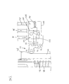
- FIG. 3 shows a sectional side view of a filling assembly in a retracted position.
- FIG. 4 shows a further sectional side view of the filling assembly in an inserted position.
- FIG. 5 shows a further sectional side view of the filling assembly in an extended position.
- FIG. 6 shows a schematic view of a valve in a first position.
- FIG. 7 shows a schematic view of a valve in a second position.
- the filling station 10 for filling containers 11 with a liquid is shown.
- the filling station comprises a number of container holders 12 which define respective container positions 14 .
- Two container holders are indicated but in total twenty holders are provided. A different number is also possible.
- the container holders are semi-cylindrical cavities in a holder frame 16 but other types of holders are possible.
- the container holders are arranged in a circle for rotary movement in the direction of arrow 15 .
- the filling station 10 further comprises a number of filling assemblies 20 .
- Each filling assembly is associated with a container holder 12 .
- the filling assemblies are positioned directly above the associated container holders.
- the filling assemblies 20 are supported by a rotary support frame 18 which rotates about a main axis 19 .
- the container holders 12 and the associated filling assemblies 20 are mounted on a rotary support frame to form a carousel which makes a rotary movement.
- Multiple container holders 12 are arranged in a circle on the holder frame 16 for rotary movement.
- the multiple filling assemblies 20 are also arranged in a circle.
- the rotary support frame 18 comprises a number of nozzle assembly guides 21 .
- the nozzle assembly guides are cavities in the rotary support frame and extend through the rotary support frame from the top 120 to the bottom 121 thereof.
- Each nozzle assembly guide further comprises an outwardly extending cavity part 27 which extends to the outer side 23 of the rotary support frame 18 .
- the filling assemblies 20 rotate in a synchronized manner with the container holders 12 .
- Each filling assembly comprises a reciprocating nozzle assembly 40 and a reciprocating lid assembly 22 .
- the reciprocating nozzle assembly 40 is shown above the rotary support frame 18 .
- the reciprocating nozzle assembly extends through the nozzle assembly guide 21 of the support frame 18 and comprises a cam 80 .
- the cam runs in a cam track 81 which is defined in a cylindrical body 85 which is fixed, i.e. stationary.
- the cam track 81 has an inclined section 83 , also indicated as closing section. When the cam 80 runs through the inclined section 83 , the reciprocating nozzle assembly 40 moves downward.
- the reciprocating nozzle assembly 40 extends inside a tube 38 of the reciprocating lid assembly 22 and comprises a number of nozzles 42 .
- the nozzles 42 have the form of a needle.
- the nozzle assembly 40 comprises a needle support 41 and multiple needles 42 .
- the nozzles are fed with liquid via feed channel 43 inside the nozzle assembly.
- the feed channel 43 inside the nozzle assembly is connected with the outside feed channel 36 coming from the valve via connector 45 .
- the reciprocating nozzle assembly 40 is constructed to make a first reciprocating movement in the direction of arrow 25 relative to the container holder 12 and relative to the reciprocating lid assembly 22 from a retracted nozzle position in which a nozzle 42 is retracted from the container to an inserted nozzle position in which the nozzle 42 is inserted into the container 11 .
- the nozzles 42 are shown in the retracted nozzle position.
- the nozzles are shown in the inserted nozzle position.
- Each filling assembly further comprises a reciprocating lid assembly 22 which comprises a lid member 30 (shown in FIG. 2 ) which is described further below.
- the reciprocating lid assembly is configured to make a reciprocating movement as indicated by arrow 24 relative to the associated container holder 12 in a direction towards a filling opening 26 of the container 11 which is positioned in the container holder and back in a direction away from the filling opening 26 of the container.
- the reciprocating lid assembly 22 also makes a reciprocating movement relative to the associated reciprocating nozzle assembly 40 .
- the reciprocating nozzle assembly and the reciprocating lid assembly are coaxial.
- the reciprocating nozzle assembly and the reciprocating lid assembly are arranged in a sliding manner and have sliding couplings 110 to enable the sliding movement.
- the reciprocating lid assembly 22 is under pre-tension by a pre-tension device in the form of a spring 28 in the direction of the filling opening 26 .
- a pre-tension device in the form of a spring 28 in the direction of the filling opening 26 .
- the spring 28 urges the lid member from a retracted lid position to an extended position. When a container is present, the lid member does not reach the extended position but engages the filling opening 26 of the container 11 at a closed lid position. In the closed lid position the lid member at least partially closes the filling opening during filling.
- lid member is disclosed as “engaging” the opening, the skilled person will understand that this means that the lid member will generally engage the rim of the opening.
- the spring urges the lid member 30 to the extended position in case there is no container present in the container position.
- the closed lid position lies between the retracted lid position and the extended lid position.
- the spring 28 holds the lid member against the filling opening.
- the extended position is located below the closed lid position.
- a feed channel 36 is provided for each filling assembly 20 .
- a valve 34 in the feed channel 36 is coupled to an associated reciprocating lid assembly 22 via a valve coupling 32 .
- the valve coupling 32 switches the valve to a filling position in the closed lid position and switches the valve to a return position in the extended position.
- the feed channel In the filling position the feed channel is open.
- a return channel 37 extends from the valve 34 back to a reservoir. In the return position of the valve, the valve closes the feed channel 36 and opens the return channel 37 to prevent liquid from being ejected onto the empty container position 12 . Instead, the liquid returns via the return channel.
- the lid member 30 comprises multiple openings 44 .
- the nozzles 42 move through these opening 44 to be inserted into the container for filling the container with a liquid.
- the reciprocating nozzle assembly 40 and the reciprocating lid assembly 22 first move jointly, i.e. in a joint movement, toward the filling opening 26 .
- the reciprocating nozzle assembly is moved directly by the cam 80 which moves along the curved cam track section 83 .
- the reciprocating lid assembly is urged by the spring 28 and is allowed to move because a stop member 61 on the reciprocating nozzle assembly is moved toward the filling opening.
- the stop member 61 acts on a mating stop member 60 of the reciprocating lid assembly 22 .
- the reciprocating lid assembly 22 When the stop member 61 of the reciprocating nozzle assembly moves toward the filling opening, the reciprocating lid assembly 22 follows this movement. The stop members 60 , 61 stay engaged during this movement. Once the lid member 30 of the reciprocating lid assembly 22 engages the filling opening 26 , the reciprocating lid assembly 22 stops.
- the stop members 60 , 61 disengage. From this point onward, the reciprocating nozzle assembly continues to be moved by the cam 80 , while the reciprocating lid assembly 22 remains stationary.
- the nozzles 42 are inserted into the container 11 to the inserted nozzle position. To this end, the nozzle assembly 40 is moved further downward by the cam track 81 .
- the container is filled by pumping liquid through a feed channel 36 , through the valve 34 and onwards through the feed channel 36 , through the nozzles 42 and into the container 11 .
- the pump itself does not form part of the present invention.
- the nozzle assembly 40 is retracted. This is brought about by another inclined section of the cam track 81 .
- This inclined section is inclined upward to force an upward movement of the cam. In FIG. 1 this section is on the rear side of the body 85 .
- the nozzle assembly 40 moves upward while the reciprocating lid assembly 22 remains stationary and the lid member 30 remains engaged with the filling opening 26 .
- the nozzles 42 move through the openings in the lid member.
- the lid member 30 prevents the non-wovens from being pulled out of the container by the retracting nozzles 42 .
- the stop member 61 of the nozzle assembly 40 engages the stop member 60 of the reciprocating lid assembly again. From this point onward the reciprocating nozzle assembly 40 and the reciprocating lid assembly 22 make a joint movement away from the filling opening, and the lid member 30 is disengaged from the filling opening. Basically, the reciprocating nozzle assembly 40 pulls the reciprocating lid assembly against the action of the spring 28 away from the filling opening. The retracting movement will typically be upward, although other directions are possible.
- the retracting may take place during the filling. This has the advantage of a further time gain since two steps are carried out simultaneously. Moreover, this has the positive effect that the liquid is distributed over the volume of the non-wovens. Some non-wovens do not absorb liquid very well, and the distribution ensures that the complete or substantially complete volume of the non-woven is filled with liquid.
- FIG. 5 a situation is shown in which there is no container present in the container holder 12 .
- the lid member 30 is not stopped by a filling opening of a container and the reciprocating lid assembly 22 continues to move with the reciprocating nozzle assembly 40 to the extended position which is beyond the closed lid position.
- the lid member eventually engages the container holder 12 itself and stops in that extended lid position.
- the valve coupling 32 between the reciprocating lid assembly 22 and the valve 34 comprises a coupling member 46 in the form of a bar having a valve cam 48 .
- the valve cam is an enlarged portion of the coupling member 46 .
- the valve cam reciprocates with the reciprocating lid assembly.
- the bar is mounted to a lower end of the reciprocating lid assembly 22 via a screw 50 , but any other connection is conceivable.
- the valve cam 48 engages an operating member 52 of the valve, which in this embodiment comprises a pivotable arm 54 having a round abutment surface 55 .
- the pivotable arm 54 engages a button 56 of the valve.
- the cam 48 engages the abutment surface of the operating member 52 .
- the pivotable arm 54 pivots and presses the button 56 which closes the valve of the feed channel 36 .
- the nozzles 42 stay inside the tube 38 . It is noted that the nozzles 42 move downwards to the same position as when a container would be present. However, due to the lower position of the lid member 30 and the tube 38 , the nozzles 4 do not protrude from the lid member.
- the cam 80 with the help of the spring 28 and the stop member 60 , 61 operates the reciprocating movement of the reciprocating nozzle assembly 40 and the reciprocating lid assembly 22 .
- the valve 34 only switches when the lid member 30 is moved to the extended position. This has an advantage that the valve is not operated unnecessarily and thereby does not wear excessively. In this way, the valve can reach a long lifespan.
- the reciprocating lid assembly makes a vertical reciprocating movement
- the reciprocating nozzle assembly also makes a vertical reciprocating movement. In this way, gravity helps during filling.
- Other orientations are of course conceivable.
- the container may comprise non-wovens or similar material for absorbing the liquid, and wherein the at least one nozzle penetrates into the non-wovens during filling of the container, and wherein the non-wovens have the tendency to stick to the nozzle during the movement of the nozzle out of the container, and wherein the lid member blocks the non-wovens from being pulled out of the container by the retracting nozzle.
- the retracting and the filling step may take place simultaneously. This results in a time gain.
- the non-wovens may not absorb the liquid very easily. By retracting and filling at the same time the liquid is distributed over the non-wovens.
- the valve 34 comprises a housing 100 and a movable member 102 inside the housing.
- the movable member is biased to the left in the figure by a compression spring 103 .
- the housing defines an entry passage 104 for the feed channel 36 and an exit passage 106 for the feed channel.
- a return passage 108 is also defined for the return channel.
- FIG. 6 shows the filling position and FIG. 7 shows the return position.
- the movable member 102 comprises the button 56 discussed above.
- the filling station disclosed above provides a suitable variant to known filling stations.
- Filling station ( 10 ) for filling containers ( 11 ) with a liquid comprising:
- valve coupling ( 32 ) between the reciprocating lid assembly ( 40 ) and the valve ( 34 ) comprises a valve cam ( 48 ) which reciprocates with the reciprocating lid assembly, wherein the valve cam engages an operating member ( 52 ) of the valve.
- filling station ( 10 ) according to any of the preceding clauses, wherein the multiple container holders ( 12 ) and associated filling assemblies ( 20 ) are mounted on a rotary frame to form a carousel which makes a rotary movement, wherein the multiple container holders are arranged in a circle for rotary movement, and wherein the multiple filling assemblies are also arranged in a circle, and wherein the filling station comprises a nozzle assembly cam track ( 81 ), and wherein each reciprocating nozzle assembly comprises a nozzle assembly cam ( 80 ) which runs through the nozzle assembly cam track, and wherein the nozzle assembly cam track comprises a cam track closing section ( 83 ) which is configured to allow the spring to move the reciprocating lid assembly to a closed lid position, and wherein the cam track comprises a retracting section configured to retract the lid member from the filling opening of the container.
- Filling station ( 10 ) according to any of the preceding clauses, comprising a filling assembly support frame ( 18 ) which comprises a number of nozzle assembly guides which guide the associated reciprocating nozzle assembly.
- the nozzle comprises one or more needles ( 42 ) which extend through the one or more openings in the lid member ( 30 ).
- Method of filling containers ( 11 ) with a liquid comprising providing the filling station ( 10 ) according to clause 1, and carrying out either process a) or process b),
- process a) comprising:
- process b) comprising:
- the container comprises non-wovens or similar material for absorbing the liquid, and wherein the at least one nozzle penetrates into the non-wovens during filling of the container, and wherein the non-wovens have the tendency to stick to the nozzle during the movement of the nozzle out of the container, and wherein the lid member blocks the non-wovens from being pulled out of the container by the retracting nozzle.
Landscapes
- Engineering & Computer Science (AREA)
- Mechanical Engineering (AREA)
- Basic Packing Technique (AREA)
Applications Claiming Priority (3)
| Application Number | Priority Date | Filing Date | Title |
|---|---|---|---|
| NL2012833 | 2014-05-16 | ||
| NL2012833A NL2012833B1 (en) | 2014-05-16 | 2014-05-16 | Filling station for filling containers with a liquid. |
| PCT/NL2015/050338 WO2015174837A1 (en) | 2014-05-16 | 2015-05-12 | Filling station for filling containers with a liquid |
Publications (2)
| Publication Number | Publication Date |
|---|---|
| US20170217615A1 US20170217615A1 (en) | 2017-08-03 |
| US10214306B2 true US10214306B2 (en) | 2019-02-26 |
Family
ID=51398800
Family Applications (1)
| Application Number | Title | Priority Date | Filing Date |
|---|---|---|---|
| US15/310,818 Active US10214306B2 (en) | 2014-05-16 | 2015-05-12 | Filling station for filling containers with a liquid |
Country Status (6)
| Country | Link |
|---|---|
| US (1) | US10214306B2 (pl) |
| EP (1) | EP3142929B1 (pl) |
| HU (1) | HUE038817T2 (pl) |
| NL (1) | NL2012833B1 (pl) |
| PL (1) | PL3142929T3 (pl) |
| WO (1) | WO2015174837A1 (pl) |
Cited By (3)
| Publication number | Priority date | Publication date | Assignee | Title |
|---|---|---|---|---|
| US20180179042A1 (en) * | 2016-12-27 | 2018-06-28 | Altria Client Services Llc | Apparatus for filling cartridges of e-vapor devices |
| US20180229874A1 (en) * | 2015-08-07 | 2018-08-16 | Indag Gesellschaft für Industriebedarf mbH & Co. Betriebs KG | Method for filling and welding film bags and a filling and welding device therefor |
| US11186396B2 (en) * | 2017-02-15 | 2021-11-30 | G.D Societa' Per Azioni | Method and device for filling a cartridge for an aerosol generating device with a liquid |
Families Citing this family (3)
| Publication number | Priority date | Publication date | Assignee | Title |
|---|---|---|---|---|
| NL2012831B1 (en) * | 2014-05-16 | 2016-03-02 | Sluis Cigar Machinery Bv | Filling device. |
| ITUA20161764A1 (it) * | 2016-03-17 | 2017-09-17 | Tecnicoll Srl | Macchina dosatrice di composizioni fluide o fluidificabili |
| CN109466835B (zh) * | 2018-11-09 | 2023-12-15 | 广州达意隆包装机械股份有限公司 | 一种旋转式灌装机 |
Citations (21)
| Publication number | Priority date | Publication date | Assignee | Title |
|---|---|---|---|---|
| US2839094A (en) * | 1956-10-15 | 1958-06-17 | Horix Mfg Company | Valve for liquid filling apparatus |
| US3037536A (en) * | 1959-03-06 | 1962-06-05 | Karl Kiefer Machine Company | Pressure filling apparatus with vacuum level control |
| US3150697A (en) * | 1961-05-05 | 1964-09-29 | U S Bottlers Machinery Company | Filling tube assembly for automatic filling machines |
| US3176731A (en) | 1961-12-01 | 1965-04-06 | Chemetron Corp | Filling valve for easy mounting and dismounting from a filling machine |
| US3335767A (en) * | 1964-12-08 | 1967-08-15 | M R M Company Inc | Accurate measure rotary filling machine |
| US3354614A (en) * | 1964-10-08 | 1967-11-28 | Lily Tulip Cup Corp | Dispensing, filling and capping of portion containers |
| US3461923A (en) * | 1966-10-31 | 1969-08-19 | Consolidated Packaging Machine | Submergible filling head |
| US3516455A (en) * | 1967-05-01 | 1970-06-23 | Automatic Sprinkler Corp | Container-filling apparatus |
| US3580298A (en) * | 1969-09-12 | 1971-05-25 | Pneumatic Scale Corp | Container filling machine |
| US3605827A (en) * | 1969-08-04 | 1971-09-20 | U S Bottlers Machinery Co | Rotary filling machine |
| US3720242A (en) * | 1970-10-15 | 1973-03-13 | Continental Can Co | Container filling apparatus |
| US3837378A (en) | 1972-04-18 | 1974-09-24 | Takeda Chemical Industries Ltd | Device for the transport and filling of ampoules |
| US3841363A (en) * | 1971-12-30 | 1974-10-15 | Rostgo Int Corp | Container filling machine |
| US3905404A (en) * | 1974-01-07 | 1975-09-16 | James R Cox | Container filling control |
| US4375826A (en) * | 1981-04-06 | 1983-03-08 | Anderson Bros. Mfg. Co. | Container filling machine |
| US4787428A (en) * | 1986-07-21 | 1988-11-29 | Seva | Container filling apparatus with selectively communicated chambers |
| US5417260A (en) * | 1992-10-09 | 1995-05-23 | Perrier; Rene | Metering-out device, a metering-out valve, and apparatus for timed metering out of liquid |
| US7350546B2 (en) * | 2003-11-10 | 2008-04-01 | Adcor Industries, Inc. | Filling valve apparatus having a quick connect/release mechanism |
| US8312901B2 (en) | 2008-06-19 | 2012-11-20 | Krones Ag | Open jet filling system |
| US8505594B2 (en) | 2006-04-15 | 2013-08-13 | Khs Gmbh | Beverage bottling plant having a filling machine with multiple beverage filling elements, a filling machine with multiple beverage filling elements, a filling element and related method |
| US20170217607A1 (en) * | 2014-05-16 | 2017-08-03 | Sluis Cigar Machinery B.V. | Filling device |
-
2014
- 2014-05-16 NL NL2012833A patent/NL2012833B1/en not_active IP Right Cessation
-
2015
- 2015-05-12 US US15/310,818 patent/US10214306B2/en active Active
- 2015-05-12 HU HUE15729257A patent/HUE038817T2/hu unknown
- 2015-05-12 EP EP15729257.4A patent/EP3142929B1/en not_active Not-in-force
- 2015-05-12 PL PL15729257T patent/PL3142929T3/pl unknown
- 2015-05-12 WO PCT/NL2015/050338 patent/WO2015174837A1/en not_active Ceased
Patent Citations (23)
| Publication number | Priority date | Publication date | Assignee | Title |
|---|---|---|---|---|
| US2839094A (en) * | 1956-10-15 | 1958-06-17 | Horix Mfg Company | Valve for liquid filling apparatus |
| US3037536A (en) * | 1959-03-06 | 1962-06-05 | Karl Kiefer Machine Company | Pressure filling apparatus with vacuum level control |
| US3150697A (en) * | 1961-05-05 | 1964-09-29 | U S Bottlers Machinery Company | Filling tube assembly for automatic filling machines |
| US3176731A (en) | 1961-12-01 | 1965-04-06 | Chemetron Corp | Filling valve for easy mounting and dismounting from a filling machine |
| US3354614A (en) * | 1964-10-08 | 1967-11-28 | Lily Tulip Cup Corp | Dispensing, filling and capping of portion containers |
| US3335767A (en) * | 1964-12-08 | 1967-08-15 | M R M Company Inc | Accurate measure rotary filling machine |
| US3461923A (en) * | 1966-10-31 | 1969-08-19 | Consolidated Packaging Machine | Submergible filling head |
| US3516455A (en) * | 1967-05-01 | 1970-06-23 | Automatic Sprinkler Corp | Container-filling apparatus |
| US3605827A (en) * | 1969-08-04 | 1971-09-20 | U S Bottlers Machinery Co | Rotary filling machine |
| US3580298A (en) * | 1969-09-12 | 1971-05-25 | Pneumatic Scale Corp | Container filling machine |
| US3720242A (en) * | 1970-10-15 | 1973-03-13 | Continental Can Co | Container filling apparatus |
| US3841363A (en) * | 1971-12-30 | 1974-10-15 | Rostgo Int Corp | Container filling machine |
| US3837378A (en) | 1972-04-18 | 1974-09-24 | Takeda Chemical Industries Ltd | Device for the transport and filling of ampoules |
| US3905404A (en) * | 1974-01-07 | 1975-09-16 | James R Cox | Container filling control |
| US4375826A (en) * | 1981-04-06 | 1983-03-08 | Anderson Bros. Mfg. Co. | Container filling machine |
| US4787428A (en) * | 1986-07-21 | 1988-11-29 | Seva | Container filling apparatus with selectively communicated chambers |
| US5417260A (en) * | 1992-10-09 | 1995-05-23 | Perrier; Rene | Metering-out device, a metering-out valve, and apparatus for timed metering out of liquid |
| US7350546B2 (en) * | 2003-11-10 | 2008-04-01 | Adcor Industries, Inc. | Filling valve apparatus having a quick connect/release mechanism |
| US7661449B2 (en) * | 2003-11-10 | 2010-02-16 | Adcoriindustries, Inc. | Filling valve apparatus for a beverage filling machine |
| US7921886B2 (en) * | 2003-11-10 | 2011-04-12 | Adcor Industries, Inc. | Filling valve apparatus for a beverage filling machine |
| US8505594B2 (en) | 2006-04-15 | 2013-08-13 | Khs Gmbh | Beverage bottling plant having a filling machine with multiple beverage filling elements, a filling machine with multiple beverage filling elements, a filling element and related method |
| US8312901B2 (en) | 2008-06-19 | 2012-11-20 | Krones Ag | Open jet filling system |
| US20170217607A1 (en) * | 2014-05-16 | 2017-08-03 | Sluis Cigar Machinery B.V. | Filling device |
Non-Patent Citations (2)
| Title |
|---|
| Third Party Observation for Application No. EP 15729257.4, dated Mar. 1, 2018, 4 pages. |
| Third Party Observation for Application No. EP 15729257.4, dated Mar. 13, 2018, 3 pages. |
Cited By (7)
| Publication number | Priority date | Publication date | Assignee | Title |
|---|---|---|---|---|
| US20180229874A1 (en) * | 2015-08-07 | 2018-08-16 | Indag Gesellschaft für Industriebedarf mbH & Co. Betriebs KG | Method for filling and welding film bags and a filling and welding device therefor |
| US20180179042A1 (en) * | 2016-12-27 | 2018-06-28 | Altria Client Services Llc | Apparatus for filling cartridges of e-vapor devices |
| US10562748B2 (en) * | 2016-12-27 | 2020-02-18 | Altria Client Services Llc | Apparatus for filling cartridges of e-vapor devices |
| US11267593B2 (en) | 2016-12-27 | 2022-03-08 | Altria Client Services Llc | Apparatus for filling cartridges of e-vapor devices |
| US11834213B2 (en) | 2016-12-27 | 2023-12-05 | Altria Client Services Llc | Apparatus for filling cartridges of e-vapor devices |
| US12534237B2 (en) | 2016-12-27 | 2026-01-27 | Altria Client Services Llc | Apparatus for filling cartridges of e-vapor devices |
| US11186396B2 (en) * | 2017-02-15 | 2021-11-30 | G.D Societa' Per Azioni | Method and device for filling a cartridge for an aerosol generating device with a liquid |
Also Published As
| Publication number | Publication date |
|---|---|
| US20170217615A1 (en) | 2017-08-03 |
| NL2012833B1 (en) | 2016-03-02 |
| PL3142929T3 (pl) | 2018-09-28 |
| WO2015174837A1 (en) | 2015-11-19 |
| EP3142929A1 (en) | 2017-03-22 |
| HUE038817T2 (hu) | 2018-11-28 |
| EP3142929B1 (en) | 2018-05-02 |
Similar Documents
| Publication | Publication Date | Title |
|---|---|---|
| US10214306B2 (en) | Filling station for filling containers with a liquid | |
| US10377516B2 (en) | Filling device | |
| EP2250950B1 (en) | Machine for the preparation of brewed beverages | |
| EP3237289B1 (en) | Device and method for filling cartridges of e-cigarettes with a liquid | |
| US20120000371A1 (en) | Machine for the preparation of beverages by infusion using cartridges | |
| US10279363B2 (en) | Trigger-type liquid ejector | |
| EP2564967B1 (en) | Automatic wire threader for wire electric discharge machining apparatus | |
| JP6511385B2 (ja) | トリガー式液体噴出器 | |
| JP6726463B2 (ja) | トリガー式液体噴出器 | |
| ES2960302T3 (es) | Conjunto de agarre para cabezal aplicador de tapas para la aplicación de tapas en recipientes o botellas | |
| JP6307608B2 (ja) | 粉末食品を収容するカプセルを用いて飲料を作るための水平ユニット | |
| KR20180082319A (ko) | 자동식 모낭 이식 식모기 | |
| JP6546859B2 (ja) | トリガー式液体噴出器 | |
| US20170251862A1 (en) | A dispensing assembly for machines for preparing liquid products by means of capsules | |
| JP2016203141A (ja) | トリガー式液体噴出器 | |
| JP6307609B2 (ja) | 粉末食品を収容するカプセルを用いて飲料を作るための水平ユニット | |
| JP6476060B2 (ja) | トリガー式液体噴出器 | |
| JP2021120290A (ja) | トリガー式液体噴出器 | |
| CN107105924A (zh) | 用于经由胶囊制备液体产品的机器 | |
| JP2017080724A (ja) | トリガー式液体噴出器 | |
| CN116035293A (zh) | 雾化头装配设备 | |
| EP4424425A1 (en) | Trigger-type liquid sprayer | |
| EP4424424A1 (en) | Trigger-type liquid sprayer | |
| HK1224533B (en) | Horizontal unit for making beverages using capsules containing powdered food substances | |
| HK1224533A1 (en) | Horizontal unit for making beverages using capsules containing powdered food substances |
Legal Events
| Date | Code | Title | Description |
|---|---|---|---|
| AS | Assignment |
Owner name: SLUIS CIGAR MACHINERY B.V., NETHERLANDS Free format text: ASSIGNMENT OF ASSIGNORS INTEREST;ASSIGNORS:SLURINK, OSCAR;BREMAN, LAMBERT WIJNAND;REEL/FRAME:040997/0157 Effective date: 20161220 |
|
| STCF | Information on status: patent grant |
Free format text: PATENTED CASE |
|
| MAFP | Maintenance fee payment |
Free format text: PAYMENT OF MAINTENANCE FEE, 4TH YEAR, LARGE ENTITY (ORIGINAL EVENT CODE: M1551); ENTITY STATUS OF PATENT OWNER: LARGE ENTITY Year of fee payment: 4 |