US10174482B2 - Construction machine - Google Patents
Construction machine Download PDFInfo
- Publication number
- US10174482B2 US10174482B2 US15/399,794 US201715399794A US10174482B2 US 10174482 B2 US10174482 B2 US 10174482B2 US 201715399794 A US201715399794 A US 201715399794A US 10174482 B2 US10174482 B2 US 10174482B2
- Authority
- US
- United States
- Prior art keywords
- engine
- exhaust gas
- counterweight
- treatment device
- opening
- Prior art date
- Legal status (The legal status is an assumption and is not a legal conclusion. Google has not performed a legal analysis and makes no representation as to the accuracy of the status listed.)
- Active
Links
Images


Classifications
-
- E—FIXED CONSTRUCTIONS
- E02—HYDRAULIC ENGINEERING; FOUNDATIONS; SOIL SHIFTING
- E02F—DREDGING; SOIL-SHIFTING
- E02F9/00—Component parts of dredgers or soil-shifting machines, not restricted to one of the kinds covered by groups E02F3/00 - E02F7/00
- E02F9/08—Superstructures; Supports for superstructures
- E02F9/0858—Arrangement of component parts installed on superstructures not otherwise provided for, e.g. electric components, fenders, air-conditioning units
- E02F9/0866—Engine compartment, e.g. heat exchangers, exhaust filters, cooling devices, silencers, mufflers, position of hydraulic pumps in the engine compartment
-
- B—PERFORMING OPERATIONS; TRANSPORTING
- B60—VEHICLES IN GENERAL
- B60K—ARRANGEMENT OR MOUNTING OF PROPULSION UNITS OR OF TRANSMISSIONS IN VEHICLES; ARRANGEMENT OR MOUNTING OF PLURAL DIVERSE PRIME-MOVERS IN VEHICLES; AUXILIARY DRIVES FOR VEHICLES; INSTRUMENTATION OR DASHBOARDS FOR VEHICLES; ARRANGEMENTS IN CONNECTION WITH COOLING, AIR INTAKE, GAS EXHAUST OR FUEL SUPPLY OF PROPULSION UNITS IN VEHICLES
- B60K11/00—Arrangement in connection with cooling of propulsion units
- B60K11/02—Arrangement in connection with cooling of propulsion units with liquid cooling
- B60K11/04—Arrangement or mounting of radiators, radiator shutters, or radiator blinds
-
- B—PERFORMING OPERATIONS; TRANSPORTING
- B60—VEHICLES IN GENERAL
- B60K—ARRANGEMENT OR MOUNTING OF PROPULSION UNITS OR OF TRANSMISSIONS IN VEHICLES; ARRANGEMENT OR MOUNTING OF PLURAL DIVERSE PRIME-MOVERS IN VEHICLES; AUXILIARY DRIVES FOR VEHICLES; INSTRUMENTATION OR DASHBOARDS FOR VEHICLES; ARRANGEMENTS IN CONNECTION WITH COOLING, AIR INTAKE, GAS EXHAUST OR FUEL SUPPLY OF PROPULSION UNITS IN VEHICLES
- B60K11/00—Arrangement in connection with cooling of propulsion units
- B60K11/06—Arrangement in connection with cooling of propulsion units with air cooling
-
- B—PERFORMING OPERATIONS; TRANSPORTING
- B60—VEHICLES IN GENERAL
- B60K—ARRANGEMENT OR MOUNTING OF PROPULSION UNITS OR OF TRANSMISSIONS IN VEHICLES; ARRANGEMENT OR MOUNTING OF PLURAL DIVERSE PRIME-MOVERS IN VEHICLES; AUXILIARY DRIVES FOR VEHICLES; INSTRUMENTATION OR DASHBOARDS FOR VEHICLES; ARRANGEMENTS IN CONNECTION WITH COOLING, AIR INTAKE, GAS EXHAUST OR FUEL SUPPLY OF PROPULSION UNITS IN VEHICLES
- B60K11/00—Arrangement in connection with cooling of propulsion units
- B60K11/08—Air inlets for cooling; Shutters or blinds therefor
-
- B—PERFORMING OPERATIONS; TRANSPORTING
- B60—VEHICLES IN GENERAL
- B60K—ARRANGEMENT OR MOUNTING OF PROPULSION UNITS OR OF TRANSMISSIONS IN VEHICLES; ARRANGEMENT OR MOUNTING OF PLURAL DIVERSE PRIME-MOVERS IN VEHICLES; AUXILIARY DRIVES FOR VEHICLES; INSTRUMENTATION OR DASHBOARDS FOR VEHICLES; ARRANGEMENTS IN CONNECTION WITH COOLING, AIR INTAKE, GAS EXHAUST OR FUEL SUPPLY OF PROPULSION UNITS IN VEHICLES
- B60K13/00—Arrangement in connection with combustion air intake or gas exhaust of propulsion units
- B60K13/02—Arrangement in connection with combustion air intake or gas exhaust of propulsion units concerning intake
-
- B—PERFORMING OPERATIONS; TRANSPORTING
- B60—VEHICLES IN GENERAL
- B60K—ARRANGEMENT OR MOUNTING OF PROPULSION UNITS OR OF TRANSMISSIONS IN VEHICLES; ARRANGEMENT OR MOUNTING OF PLURAL DIVERSE PRIME-MOVERS IN VEHICLES; AUXILIARY DRIVES FOR VEHICLES; INSTRUMENTATION OR DASHBOARDS FOR VEHICLES; ARRANGEMENTS IN CONNECTION WITH COOLING, AIR INTAKE, GAS EXHAUST OR FUEL SUPPLY OF PROPULSION UNITS IN VEHICLES
- B60K13/00—Arrangement in connection with combustion air intake or gas exhaust of propulsion units
- B60K13/04—Arrangement in connection with combustion air intake or gas exhaust of propulsion units concerning exhaust
-
- E—FIXED CONSTRUCTIONS
- E02—HYDRAULIC ENGINEERING; FOUNDATIONS; SOIL SHIFTING
- E02F—DREDGING; SOIL-SHIFTING
- E02F9/00—Component parts of dredgers or soil-shifting machines, not restricted to one of the kinds covered by groups E02F3/00 - E02F7/00
- E02F9/08—Superstructures; Supports for superstructures
- E02F9/0808—Improving mounting or assembling, e.g. frame elements, disposition of all the components on the superstructures
-
- E—FIXED CONSTRUCTIONS
- E02—HYDRAULIC ENGINEERING; FOUNDATIONS; SOIL SHIFTING
- E02F—DREDGING; SOIL-SHIFTING
- E02F9/00—Component parts of dredgers or soil-shifting machines, not restricted to one of the kinds covered by groups E02F3/00 - E02F7/00
- E02F9/08—Superstructures; Supports for superstructures
- E02F9/0858—Arrangement of component parts installed on superstructures not otherwise provided for, e.g. electric components, fenders, air-conditioning units
- E02F9/0891—Lids or bonnets or doors or details thereof
-
- E—FIXED CONSTRUCTIONS
- E02—HYDRAULIC ENGINEERING; FOUNDATIONS; SOIL SHIFTING
- E02F—DREDGING; SOIL-SHIFTING
- E02F9/00—Component parts of dredgers or soil-shifting machines, not restricted to one of the kinds covered by groups E02F3/00 - E02F7/00
- E02F9/18—Counterweights
-
- E—FIXED CONSTRUCTIONS
- E02—HYDRAULIC ENGINEERING; FOUNDATIONS; SOIL SHIFTING
- E02F—DREDGING; SOIL-SHIFTING
- E02F9/00—Component parts of dredgers or soil-shifting machines, not restricted to one of the kinds covered by groups E02F3/00 - E02F7/00
- E02F9/24—Safety devices, e.g. for preventing overload
-
- F—MECHANICAL ENGINEERING; LIGHTING; HEATING; WEAPONS; BLASTING
- F01—MACHINES OR ENGINES IN GENERAL; ENGINE PLANTS IN GENERAL; STEAM ENGINES
- F01N—GAS-FLOW SILENCERS OR EXHAUST APPARATUS FOR MACHINES OR ENGINES IN GENERAL; GAS-FLOW SILENCERS OR EXHAUST APPARATUS FOR INTERNAL COMBUSTION ENGINES
- F01N3/00—Exhaust or silencing apparatus having means for purifying, rendering innocuous, or otherwise treating exhaust
- F01N3/02—Exhaust or silencing apparatus having means for purifying, rendering innocuous, or otherwise treating exhaust for cooling, or for removing solid constituents of, exhaust
-
- F—MECHANICAL ENGINEERING; LIGHTING; HEATING; WEAPONS; BLASTING
- F01—MACHINES OR ENGINES IN GENERAL; ENGINE PLANTS IN GENERAL; STEAM ENGINES
- F01P—COOLING OF MACHINES OR ENGINES IN GENERAL; COOLING OF INTERNAL-COMBUSTION ENGINES
- F01P11/00—Component parts, details, or accessories not provided for in, or of interest apart from, groups F01P1/00 - F01P9/00
- F01P11/10—Guiding or ducting cooling-air, to, or from, liquid-to-air heat exchangers
-
- F—MECHANICAL ENGINEERING; LIGHTING; HEATING; WEAPONS; BLASTING
- F01—MACHINES OR ENGINES IN GENERAL; ENGINE PLANTS IN GENERAL; STEAM ENGINES
- F01P—COOLING OF MACHINES OR ENGINES IN GENERAL; COOLING OF INTERNAL-COMBUSTION ENGINES
- F01P5/00—Pumping cooling-air or liquid coolants
- F01P5/02—Pumping cooling-air; Arrangements of cooling-air pumps, e.g. fans or blowers
- F01P5/06—Guiding or ducting air to, or from, ducted fans
-
- B—PERFORMING OPERATIONS; TRANSPORTING
- B60—VEHICLES IN GENERAL
- B60Y—INDEXING SCHEME RELATING TO ASPECTS CROSS-CUTTING VEHICLE TECHNOLOGY
- B60Y2200/00—Type of vehicle
- B60Y2200/40—Special vehicles
- B60Y2200/41—Construction vehicles, e.g. graders, excavators
- B60Y2200/412—Excavators
-
- E—FIXED CONSTRUCTIONS
- E02—HYDRAULIC ENGINEERING; FOUNDATIONS; SOIL SHIFTING
- E02F—DREDGING; SOIL-SHIFTING
- E02F3/00—Dredgers; Soil-shifting machines
- E02F3/04—Dredgers; Soil-shifting machines mechanically-driven
- E02F3/28—Dredgers; Soil-shifting machines mechanically-driven with digging tools mounted on a dipper- or bucket-arm, i.e. there is either one arm or a pair of arms, e.g. dippers, buckets
- E02F3/30—Dredgers; Soil-shifting machines mechanically-driven with digging tools mounted on a dipper- or bucket-arm, i.e. there is either one arm or a pair of arms, e.g. dippers, buckets with a dipper-arm pivoted on a cantilever beam, i.e. boom
- E02F3/32—Dredgers; Soil-shifting machines mechanically-driven with digging tools mounted on a dipper- or bucket-arm, i.e. there is either one arm or a pair of arms, e.g. dippers, buckets with a dipper-arm pivoted on a cantilever beam, i.e. boom working downwardly and towards the machine, e.g. with backhoes
-
- F—MECHANICAL ENGINEERING; LIGHTING; HEATING; WEAPONS; BLASTING
- F01—MACHINES OR ENGINES IN GENERAL; ENGINE PLANTS IN GENERAL; STEAM ENGINES
- F01N—GAS-FLOW SILENCERS OR EXHAUST APPARATUS FOR MACHINES OR ENGINES IN GENERAL; GAS-FLOW SILENCERS OR EXHAUST APPARATUS FOR INTERNAL COMBUSTION ENGINES
- F01N2260/00—Exhaust treating devices having provisions not otherwise provided for
- F01N2260/02—Exhaust treating devices having provisions not otherwise provided for for cooling the device
-
- F—MECHANICAL ENGINEERING; LIGHTING; HEATING; WEAPONS; BLASTING
- F01—MACHINES OR ENGINES IN GENERAL; ENGINE PLANTS IN GENERAL; STEAM ENGINES
- F01N—GAS-FLOW SILENCERS OR EXHAUST APPARATUS FOR MACHINES OR ENGINES IN GENERAL; GAS-FLOW SILENCERS OR EXHAUST APPARATUS FOR INTERNAL COMBUSTION ENGINES
- F01N2270/00—Mixing air with exhaust gases
- F01N2270/02—Mixing air with exhaust gases for cooling exhaust gases or the apparatus
-
- F—MECHANICAL ENGINEERING; LIGHTING; HEATING; WEAPONS; BLASTING
- F01—MACHINES OR ENGINES IN GENERAL; ENGINE PLANTS IN GENERAL; STEAM ENGINES
- F01P—COOLING OF MACHINES OR ENGINES IN GENERAL; COOLING OF INTERNAL-COMBUSTION ENGINES
- F01P1/00—Air cooling
- F01P2001/005—Cooling engine rooms
Definitions
- the present invention relates to construction machines such as a hydraulic excavator provided with a counterweight and an engine in rear of a vehicle body frame, for example.
- a hydraulic excavator as a representative example of construction machines is configured with an automotive lower traveling structure, an upper revolving structure that is mounted on the lower traveling structure to be capable of revolving thereon and a front device that is mounted on the upper revolving structure to be capable of tilting and lifting thereto.
- the upper revolving structure of the hydraulic excavator comprises a vehicle body frame that is formed as a support structure, a counterweight that is provided to extend in a left-right direction of the vehicle body frame in the rear end to the vehicle body frame for acting as a weight balance to the front device, an engine that is positioned in the front side to the counterweight and is mounted on the vehicle body frame in a horizontal state of extending in the left-right direction, a hydraulic pump that is provided in the engine to be positioned in one side of the left-right direction of the vehicle body frame, an exhaust gas post-treatment device that is connected to an exhaust gas side of the engine to be positioned above the hydraulic pump and performs post-treatment of an exhaust gas discharged from the engine, a firewall that is provided as a partition between an engine room in which the engine and the exhaust gas post-treatment device are arranged and a pump room in which the hydraulic pump is arranged, a cooling fan that is provided in the engine room to be positioned on the other side of the left-right direction of the vehicle body frame and
- the heat exchanger can cool fluid such as engine cooling water and hydraulic oil with the cooling air by the cooling fan.
- Patent Document 1 Japanese Patent Laid-Open No. 2003-20679 A
- the exhaust gas post-treatment device is large-sized with the tightening of the exhaust gas regulations.
- the exhaust gas post-treatment device is wholly complicated along with an increase of sensors to be mounted.
- the large-sized exhaust gas post-treatment device is made higher in heat quantity to cause a wide range of the periphery to be high in temperature. Therefore, the sensors are unfortunately caused to rise in temperature by the heat of the exhaust gas post-treatment device.
- the present invention is made in view of the aforementioned problems in the conventional arts, and an object of the present invention is to provide a construction machine that can cool an exhaust gas post-treatment device with circulation of cooling air within an engine room.
- a construction machine comprises: a vehicle body frame that is formed as a support structure; a counterweight that is provided to extend in a left-right direction of the vehicle body frame in the rear end to the vehicle body frame for acting as a weight balance to a front device; an engine that is positioned in the front side to the counterweight and is mounted on the vehicle body frame in a horizontal state of extending in the left-right direction; a hydraulic pump that is provided in the engine to be positioned in one side of the left-right direction of the vehicle body frame; an exhaust gas post-treatment device that is connected to an exhaust gas side of the engine to be positioned above the hydraulic pump and performs post-treatment of an exhaust gas discharged from the engine; a firewall that is provided as a partition between an engine room in which the engine and the exhaust gas post-treatment device are arranged and a pump room in which the hydraulic pump is arranged; a cooling fan that is provided in the engine room to be positioned on the other side of the left-right direction of
- FIG. 1 is a side view showing a wheel type hydraulic excavator according to an embodiment in the present invention.
- FIG. 2 is a plan view showing a revolving frame, a counterweight, an engine, a heat exchanger, an exhaust gas post-treatment device and the like of an upper revolving structure with an exterior cover and a cab being removed.
- FIG. 3 is a rear view showing a rear part of the upper revolving structure with the counterweight being removed, as viewed from the rear side in FIG. 1 .
- FIG. 4 is a rear view showing the counterweight as viewed from the rear side in FIG. 1 .
- FIG. 5 is a cross sectional view showing flow of cooling air in a heat exchanger upstream room and in an engine room as enlarged in a direction of arrows V-V in FIG. 1 .
- FIG. 6 is a perspective cross sectional view showing the revolving frame, the counterweight, a hydraulic pump, a firewall, an outflow opening, an exhaust opening and the like as viewed in a direction of arrows VI-VI in FIG. 3 .
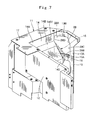
- FIG. 7 is a perspective view showing the firewall in FIG. 6 in a single unit.
- FIG. 8 is a perspective view showing the firewall in the single unit as viewed from a right oblique upper side in FIG. 7 .
- a wheel type hydraulic excavator 1 is provided with an automotive wheel type lower traveling structure 2 having left and right front wheels 2 A and left and right rear wheels 2 B (only the right wheel is shown in both of the front and rear wheels).
- the hydraulic excavator 1 includes the lower traveling structure 2 , an upper revolving structure 3 that is mounted on the lower traveling structure 2 to be capable of revolving thereon and a front device 4 that is provided on the front side in the upper revolving structure 3 to be capable of lifting and tilting thereto.
- a revolving frame 5 is formed as a support structure of the upper revolving structure 3 , and constitutes a vehicle body frame by the present invention.
- the revolving frame 5 is mounted on the lower traveling structure 2 to be capable of revolving thereon, and the front device 4 is mounted on the front side of the revolving frame 5 . As shown in FIG.
- the revolving frame 5 includes a bottom plate 5 A composed of a thick steel plate extending in the front-rear direction and the like, a left vertical plate 5 B and a right vertical plate 5 C that are provided to rise on the bottom plate 5 A and extend in the front-rear direction at a predetermined interval in a left-right direction, a left side frame 5 D and a right side frame 5 E extending in the front-rear direction, which are respectively arranged at an interval on the left side to the left vertical plate 5 B and at an interval on the right side to the right vertical plate 5 C, a plurality of extension beams 5 F respectively that extend in the left direction from the bottom plate 5 A and the left vertical plate 5 B and support the left side frame 5 D at the distal end and extend in the right direction from the bottom plate 5 A and the right vertical plate 5 C and support the right side frame 5 E at the distal end, and an undercover 5 G that is provided to infill a clearance between the respective extension beams 5 F.
- the front device 4 is mounted to the front
- the revolving frame 5 is provided with a left rear beam 5 H and a right rear beam 5 J to be positioned at the end closer to the backside than the left and right extension beams 5 F.
- the left half of the left rear beam 5 H is inclined to the front side to correspond to an inclination of a left weight part 6 B of the counterweight 6 .
- the left part of the left rear beam 5 H to a heat exchanger 19 to be described later is inclined to the front side along a front surface 6 B 1 of the left weight part 6 B.
- the right part of the right rear beam 5 J is inclined to the front side along a front surface 6 C 1 of the right weight part 6 C.
- the counterweight 6 is provided to extend in the left-right direction in a state of being mounted on the rear sides of the left and right vertical plates 5 B, 5 C forming the revolving frame 5 .
- the counterweight 6 acts as a weight balance to the front device 4 .
- the counterweight 6 is formed to be curved in an arc shape in such a manner as to project backward at the central position in the left-right direction.
- the counterweight 6 includes a center weight part 6 A that is positioned in the center of the left-right direction to cover the rear side of an engine 7 and the heat exchanger 19 to be described later, the left weight part 6 B that is positioned in the left side of the left-right direction to cover the rear side of a heat exchanger upstream room 24 to be described later and the right weight part 6 C that is positioned in the right side of the left-right direction to cover the rear side of a hydraulic pump 8 to be described later.
- a rear surface 6 D of the counterweight 6 is formed as an arc surface having substantially constant curvature over the center weight part 6 A, the left weight part 6 B and the right weight part 6 C.
- a front surface 6 A 1 of the center weight part 6 A is formed to extend linearly in the left-right direction.
- the front surface 6 B 1 of the left weight part 6 B is formed as an inclination surface inclined to the left front side to correspond to an inclined state of the left rear beam 5 H of the revolving frame 5 .
- the front surface 6 C 1 of the right weight part 6 C is formed as an inclination surface inclined to the right front side to correspond to an inclined state of the right rear beam 5 J of the revolving frame 5 and a rear surface plate 13 of a firewall 11 to be described later.
- a left lamp device 6 E composed of a brake lamp, a winker lamp and the like is provided on a lower side position of the left weight part 6 B.
- a right lamp device 6 F is provided on a lower side position of the right weight part 6 C.
- an intake opening 27 to be described later is provided on an upper side position of the left weight part 6 B, and an exhaust opening 29 to be described later is provided on an upper side position of the right weight part 6 C.
- the engine 7 is provided on the rear side of the revolving frame 5 to be positioned in the front side to the counterweight 6 .
- the engine 7 is mounted in a horizontal state of extending in the left-right direction.
- the hydraulic pump 8 to be described later is arranged on the right side as one side in the left-right direction to the engine 7 .
- An exhaust pipe 7 A is connected to an exhaust side of the engine 7 , that is, the right side in the present embodiment, and a supercharger 7 B is provided on the midway section of the exhaust pipe 7 A. Further, an exhaust gas post-treatment device 10 to be described later is provided downstream side of the supercharger 7 B of the exhaust pipe 7 A.
- the supercharger 7 B becomes in a high temperature, and therefore, is cooled by cooling air flowing in an engine room 25 to be described later.
- the hydraulic pump 8 is provided on the engine 7 to be positioned on the right side as one side in the left-right direction to the revolving frame 5 and on the lower side of the exhaust gas post-treatment device 10 .
- the hydraulic pump 8 is driven by the engine 7 , thereby pressurizing and delivering hydraulic oil supplied from a hydraulic oil tank 21 to be described later.
- the hydraulic pump 8 is mounted on one end of the engine 7 through a mounting flange 9 (refer to FIG. 6 ). Thereby, as shown in FIG. 3 and FIG. 5 , the hydraulic pump 8 is arranged closer to the right side in the left-right direction than the firewall 11 to be described later, that is, in a pump room 26 to be described later.
- the exhaust gas post-treatment device 10 is positioned on the upper side of the hydraulic pump 8 and is connected to the exhaust side of the engine 7 . Specifically, the exhaust gas post-treatment device 10 is positioned closer to upper side than a partition plate 14 of the firewall 11 to be described later to be mounted on the engine 7 . That is, the exhaust gas post-treatment device 10 is arranged to the engine room 25 side to be described later.
- the exhaust gas post-treatment device 10 for example, oxidizes carbon monoxides (CO), hydrocarbons (HC) and the like contained in the exhaust gas discharged from the engine 7 to be removed, purifies nitrogen oxides (NOx) contained in the exhaust gas, and further reduces noises of the exhaust gas.
- the exhaust gas post-treatment device 10 includes a first treatment section 10 A to which the exhaust pipe 7 A of the engine 7 is connected, a connecting line connected to the outflow side of the first treatment section 10 A, a urea water injection valve (none is shown) that is provided in the connecting line and ejects urea water, and a second treatment section 10 B connected to the outflow side of the connecting line.
- an oxidation catalyst (not shown) is accommodated in the first treatment section 10 A.
- the oxidation catalyst causes an exhaust gas to flow therein at a predetermined temperature, thereby oxidizing carbon monoxides (CO), hydrocarbons (HC) and the like contained in the exhaust gas to be removed.
- the second treatment section 10 B is arranged, for example, side by side with the first treatment section 10 A on the right side.
- a urea selective reduction catalyst, an oxidation catalyst and the like are accommodated in the second treatment section 10 B.
- An exhaust port 10 C is provided in a rear section of the second treatment section 10 B as the downstream side thereof to project in a radial upper side, and a projection end side of the exhaust port 10 C is connected to a tail pipe 23 D 2 of an engine cover 23 D constituting an exterior cover 23 to be described later (refer to FIG. 1 ).
- an exhaust gas in a high-temperature state flows in the exhaust gas post-treatment device 10 to cause various catalysts to react. Therefore, a temperature of the exhaust gas post-treatment device 10 rises in the engine room 25 . Further, many various sensors are mounted on the exhaust gas post-treatment device 10 for enhancing treatment capabilities. Accordingly, it is required to cool the sensors to be prevented from being exposed to high temperatures to be damaged.
- the urea selective reduction catalyst selectively reduces nitrogen oxides (NOx) contained in an exhaust gas discharged from the engine 7 by ammonia generated from the urea solution regularly to be decomposed into nitrogen and water.
- the oxidation catalyst oxidizes the residual ammonia remaining after reduction of the nitrogen oxides by the urea selective reduction catalyst to be decomposed into nitrogen and water.
- the firewall 11 is positioned on the right side to the engine 7 to be arranged between the counterweight 6 and the respective tanks 20 , 21 to be described later.
- the firewall 11 functions as the partition between the engine room 25 to be described later in which the engine 7 and the exhaust gas post-treatment device 10 are arranged and the pump room 26 in which the hydraulic pump 8 is arranged.
- the firewall 11 partially configures a part of the exterior cover 23 to be described later.
- the firewall 11 includes a front surface plate 12 that is positioned in front of the hydraulic pump 8 and is provided to rise to extend in the left-right direction, a rear surface plate 13 that is positioned in rear of the hydraulic pump 8 and is provided to rise to extend in the left-right direction to face the counterweight 6 , and the partition plate 14 that is positioned between the front surface plate 12 and the rear surface plate 13 and is provided to rise to extend in the front-rear direction.
- the front surface plate 12 is formed by the structure of combining a plurality of plate members.
- the front surface plate 12 is configured by combining the plate members adapted to shapes of the fuel tank 20 and the hydraulic oil tank 21 and an arrangement situation of tubular bodies connected to the respective tanks 20 , 21 . It should be noted that the front surface plate 12 may be formed by bending one sheet of plate member.
- the rear surface plate 13 is arranged to face the respective front surfaces 6 A 1 , 6 C 1 in a position close to the right side section of the center weight part 6 A and the right weight part 6 C constituting the counterweight 6 . That is, as shown in FIG. 5 and FIG. 7 , the rear surface plate 13 is formed by a vertical plate portion 13 A extending in the left-right direction to face the front surface 6 A 1 of the center weight part 6 A and an inclined plate portion 13 B inclined forward from a right end edge of the vertical plate portion 13 A to the right side.
- the rear surface plate 13 as thus formed corresponds to a bent shape of the right rear beam 5 J of the revolving frame 5 .
- an outflow opening 28 to be described later is provided on an upper side section of the rear surface plate 13 , specifically in a height position equivalent to the second treatment section 10 B in the exhaust gas post-treatment device 10 .
- the partition plate 14 is formed as a plate body extending in the front-rear direction to be positioned between the hydraulic pump 8 and the exhaust gas post-treatment device 10 .
- the partition plate 14 is formed by an upper vertical surface portion 14 A arranged vertically to be positioned upward, an inclined surface portion 14 B inclined left side (to the engine 7 side) from a lower end edge of the upper vertical surface portion 14 A to the lower side, and a lower vertical surface portion 14 C extending downward from a lower end edge of the inclined surface portion 14 B.
- a rear corner part of an upper end portion 14 B 1 in the inclined surface portion 14 B is arranged in a position close to an upper end portion 28 A of the outflow opening 28 to be described later.
- a lower side section of the lower vertical surface portion 14 C is arranged, for example, across a base end portion of the hydraulic pump 8 in an upper side vicinity of a boundary position between the hydraulic pump 8 and the mounting flange 9 .
- the firewall 11 is provided with a space forming plate 15 that forms an air flow passage part 16 to cause cooling air to flow from the engine room 25 to the outflow opening 28 .
- the space forming plate 15 is provided between the partition plate 14 of the firewall 11 and the rear surface plate 13 .
- the space forming plate 15 is formed such that a section thereof in a position lower than the outflow opening 28 to be described later is made to an upper surface portion 15 A. That is, the space forming plate 15 is formed by extending the lower vertical surface portion 14 C of the partition plate 14 to the rear side (inclined plate portion 13 B). Specifically, the space forming plate 15 ensures a space above the triangle-shaped upper surface portion 15 A to form the air flow passage part 16 (range shown in a lattice pattern of a dashed-dotted line in FIG. 5 and FIG. 7 ) for causing cooling air to flow from the engine room 25 to the outflow opening 28 between the partition plate 14 and the rear surface plate 13 .
- the air flow passage part 16 is formed, for example, as a rear triangular pyramid shape having the upper surface portion 15 A of the space forming plate 15 as a bottom surface and a corner part of the upper end portion 14 B 1 of the inclined surface portion 14 B in the partition plate 14 as a top portion. It should be noted that the air flow passage part 16 may be formed in a shape enabling an outflow area of the outflow opening 28 to be enlarged in such a shape as to overlap in the front-rear direction with the after-mentioned exhaust opening 29 provided in the counterweight 6 , and may be formed in a shape other than the triangular pyramid.
- the air flow passage part 16 enlarges an area of a flow passage communicated from the engine room 25 to the outflow opening 28 by forming a space between the outflow opening 28 and the inclined surface portion 14 B of the partition plate 14 . Thereby, the air flow passage part 16 can enlarge the opening area of the outflow opening 28 . That is, the cooling air flowing from the engine room 25 to the outflow opening 28 goes through the air flow passage part 16 , and thereby can smoothly flow out from the outflow opening 28 having a large outflow area.
- the firewall 11 is provide with a top surface plate 17 positioned on the right side of the upper part.
- the top surface plate 17 is formed to extend horizontally in the front-rear direction to connect upper parts of the front surface plate 12 , the rear surface plate 13 and the partition plate 14 .
- the top surface plate 17 forms a part of an upper surface cover 23 A of the exterior cover 23 to be described later.
- the firewall 11 as thus configured, for example, is bolted to the extension beam 5 F corresponding to the lower part of the front surface plate 12 and the lower part of the rear surface plate 13 is bolted to the right rear beam 5 J, thus being fixed on the revolving frame 5 .
- a cooling fan 18 is provided within the engine room 25 to be positioned in the left side as the other side in the left-right direction of the revolving frame 5 .
- the cooling fan 18 is driven by the engine 7 as a power source to suck in outside air as cooling air.
- the cooling air sucked by the cooling fan 18 is supplied to an oil cooler 19 B, a radiator 19 C, an intercooler 19 D and the like in the heat exchanger 19 to be described later.
- the heat exchanger 19 is provided on the revolving frame 5 to face the cooling fan 18 . As shown in FIG. 5 , the heat exchanger 19 is provided, for example, with the oil cooler 19 B for cooling hydraulic oil, the radiator 19 C for cooling cold water of the engine 7 , and the intercooler 19 D for cooling the air pressurized by the supercharger 7 B within an angular frame-shaped support frame 19 A.
- the fuel tank 20 is mounted on the right side to the revolving frame 5 to be positioned in front of the front surface plate 12 of the firewall 11 .
- the fuel tank 20 reserves fuel to be supplied to the engine 7 , and is formed as a cuboid-shaped reservoir.
- the hydraulic oil tank 21 is mounted on the revolving frame 5 to be positioned on the left side adjacent to the fuel tank 20 .
- the hydraulic oil tank 21 reserves the hydraulic oil to be pressurized and supplied to various actuators, and is formed as a cuboid-shaped reservoir.
- a front wall plate 22 is positioned in front of the engine 7 and is provided to rise on the revolving frame 5 to extend in the left-right direction.
- the front wall plate 22 extends to a position of a left surface cover 23 B of the exterior cover 23 to be described later through a front surface of the support frame 19 A of the heat exchanger 19 from the left end of the front surface plate 12 in the firewall 11 .
- the exterior cover 23 is positioned in front of the counterweight 6 to cover the engine 7 , the hydraulic pump 8 , the exhaust gas post-treatment device 10 and the heat exchanger 19 .
- the exterior cover 23 includes the upper surface cover 23 A that covers an upward side of the engine 7 , the heat exchanger 19 and the like, the left surface cover 23 B that rises down to face the heat exchanger 19 from the left end of the upper surface cover 23 A, and the right surface cover 23 C that rises down from the right end of the upper surface cover 23 A.
- the exterior cover 23 has the engine cover 23 D projecting closer to the upper side than the upper surface cover 23 A.
- the engine cover 23 D covers the exhaust gas post-treatment device 10 , the heat exchanger 19 and the like projecting closer to the upper side than the upper surface cover 23 A.
- the left surface cover 23 B is provided with an air flow port 23 B 1 for sucking in outside air.
- an exhaust port 23 D 1 is provided in the right side position of the engine cover 23 D to discharge cooling air to an exterior from the engine room 25 .
- the engine cover 23 D is provided with a tail pipe 23 D 2 projecting upward, and the tail pipe 23 D 2 is communicated with the exhaust port 10 C of the exhaust gas post-treatment device 10 .
- the heat exchanger upstream room 24 is a space positioned in the most upstream side in a flow direction of cooling air by the cooling fan 18 .
- the heat exchanger upstream room 24 is positioned upstream of the heat exchanger 19 , and is surrounded by the undercover 5 G of the revolving frame 5 , the left weight part 6 B of the counterweight 6 , the heat exchanger 19 , the front wall plate 22 and the exterior cover 23 .
- the engine room 25 is a space for flow of the cooling air having passed through the heat exchanger 19 .
- the engine room 25 is surrounded by the revolving frame 5 , the center weight part 6 A of the counterweight 6 , the firewall 11 , the heat exchanger 19 , the front wall plate 22 and the exterior cover 23 .
- the engine 7 , the exhaust gas post-treatment device 10 and the like are arranged in the engine room 25 .
- the pump room 26 is a space separated from the engine room 25 by the firewall 11 .
- the pump room 26 is surrounded by the revolving frame 5 , the right weight part 6 C of the counterweight 6 , the firewall 11 , and the exterior cover 23 .
- the hydraulic pump 8 is arranged in the pump room 26 .
- An intake opening 27 is provided in an upper side position of the left weight part 6 B constituting the counterweight 6 .
- the intake opening 27 penetrates through the rear surface 6 D from the front surface 6 B 1 of the left weight part 6 B to be communicated with the heat exchanger upstream room 24 .
- the intake opening 27 is a passage for causing more outside air to be sucked into the heat exchanger upstream room 24 .
- the intake opening 27 is provided with dust protective screen 27 A that suppress outside dusts from entering into the heat exchanger upstream room 24 together with air.
- the dust protective screen 27 A is formed by a plate member subjected to hole machining, a mesh material or the like.
- the dust protective screen 27 A can trap foreign objects (paper dusts, leaves, insects and the like) that would enter into the engine room 25 from the intake opening 27 , and can suppress foreign objects from entering into the engine room 25 .
- the outflow opening 28 is provided on the rear surface plate 13 of the firewall 11 .
- the outflow opening 28 causes the cooling air sucked into the engine room 25 to flow out toward the counterweight 6 (exhaust opening 29 ).
- the outflow opening 28 is arranged in the upper side section of the rear surface plate 13 , specifically in a height position equivalent to the second treatment section 10 B in the exhaust gas post-treatment device 10 .
- the outflow opening 28 is formed as a quadrilateral opening having the upper end portion 28 A, a lower end portion 28 B, a left end portion 28 C, and a right end portion 28 D.
- the lower end portion 28 B of the outflow opening 28 is arranged in substantially the same height with the upper surface portion 15 A of the space forming plate 15 provided on the rear surface plate 13 .
- the outflow opening 28 is provided with the air flow passage part 16 at the front side, and thereby can be arranged to be separated from the inclined surface portion 14 B of the partition plate 14 and can largely open without interruption of the inclined surface portion 14 B.
- the hydraulic oil does not enter into the engine room 25 through the outflow opening 28 from the pump room 26 .
- the exhaust opening 29 is provided in the upper side position of the right weight part 6 C constituting the counterweight 6 .
- the exhaust opening 29 is an opening for discharging the cooling air having flowed from the outflow opening 28 to an exterior.
- the exhaust opening 29 opens to a position facing the outflow opening 28 .
- the exhaust gas post-treatment device 10 second treatment section 10 B
- the outflow opening 28 and the exhaust opening 29 are arranged in a position to overlap in the front-rear direction of the revolving frame 5 .
- the cooling air having flowed on the periphery of the exhaust gas post-treatment device 10 is discharged to an exterior through the outflow opening 28 and the exhaust opening 29 .
- the exhaust opening 29 penetrates through the rear surface 6 D from the front surface 6 C 1 of the right weight part 6 C.
- the exhaust opening 29 is formed as a quadrilateral (trapezoidal) opening having an upper end portion 29 A, a lower end portion 29 B, a left end portion 29 C and a right end portion 29 D.
- the exhaust opening 29 is arranged in substantially the same height range with the height range of the outflow opening 28 (dimension in the upper-lower direction between the upper end portion 28 A and the lower end portion 28 B).
- the exhaust opening 29 since the exhaust opening 29 opens horizontally to the rear surface 6 D of the vertical counterweight 6 , the exhaust opening 29 can suppress rain waters and dusts from entering therein as compared to a case of opening upward on the upper surface and the like.
- the exhaust opening 29 is provided with dust protective screen 29 E that suppress outside dusts from entering into the engine room 25 together with air.
- the dust protective screen 29 E as similar to the dust protective screen 27 A of the intake opening 27 , is formed by a plate member subjected to hole machining, a mesh material or the like.
- the dust protective screen 29 E can trap foreign objects (paper dusts, leaves, insects and the like) that would enter into the engine room 25 from the exhaust opening 29 , and can suppress foreign objects from entering into the engine room 25 .
- a cab 30 is mounted on the left front side of the revolving frame 5 .
- the cab 30 is provided for an operator to get in, and accommodates therein an operator's seat on which the operator sits, an operating lever for traveling, an operating lever for working and the like (none is shown).
- the hydraulic excavator 1 according to the present embodiment has the aforementioned configuration. Next, an explanation will be made of an operation of the hydraulic excavator 1 .
- An operator gets in the cab 30 and is seated on an operator's seat. In this state, the operator starts the engine 7 and operates the operating lever for traveling, thereby making it possible to drive the lower traveling structure 2 and cause the hydraulic excavator 1 to travel forward or backward. On the other hand, the operator who is seated on an operator's seat operates the operating lever for working, thus making it possible to tilt and lift the front device 4 to perform an excavating work of earth and sand, and the like.
- a part of the cooling air having passed through the engine 7 , the exhaust gas post-treatment device 10 and the like is discharged to an exterior from the exhaust port 23 D 1 of the engine cover 23 D.
- another part of the cooling air is discharged to an exterior from an opening provided in the undercover 5 G of the revolving frame 5 .
- the firewall 11 cuts in between the engine room 25 and the pump room 26 , even in a case where the hydraulic oil leaks on the periphery of the hydraulic pump 8 , the firewall 11 can prevent the leaked hydraulic oil from spreading out to the engine room 25 side.
- the exhaust gas post-treatment device is large-sized, and sensors mounted on the exhaust gas post-treatment device increase in number for the hydraulic excavator to be complicated as a whole.
- the large-sized exhaust gas post-treatment device is caused to increase in heat quantity to make a wide range of the periphery a high temperature, and besides, temperatures of the sensors are increased by the heat of the exhaust gas post-treatment device.
- the rear surface plate 13 of the firewall 11 is provided with the outflow opening 28 for causing the cooling air sucked in the engine room 25 to flow out toward the counterweight 6 .
- the right weight part 6 C of the counterweight 6 is provided with the exhaust opening 29 in a position facing the outflow opening 28 for discharging the cooling air having flowed out from the outflow opening 28 to an exterior.
- the cooling air having flowed on the periphery of the exhaust gas post-treatment device 10 can be discharged to an exterior through the outflow opening 28 provided in the firewall 11 and the exhaust opening 29 provided in the counterweight 6 .
- the outflow opening 28 and the exhaust opening 29 opens to the vicinity of the exhaust gas post-treatment device 10 , the cooling air which has increased in temperature by cooling the exhaust gas post-treatment device 10 can be smoothly discharged.
- the exhaust ports of the cooling air increase in number by the outflow opening 28 and the exhaust opening 29 , a flow amount of the cooling air used for cooling each component can increase.
- the outflow opening 28 and the exhaust opening 29 are provided to be positioned in back of (on the right side to) the engine 7 . Accordingly, it is possible to cause the cooling air to actively flow in the rear side position toward the outflow opening 28 and the exhaust opening 29 in the engine room 25 . Thereby, the supercharger 7 B which becomes high temperature by the exhaust gas can be intensively cooled by the cooling air flowing close to the rear side of the engine room 25 .
- the outflow opening 28 and the exhaust opening 29 open in the vicinity of the exhaust gas post-treatment device 10 can release the heat of the exhaust gas post-treatment device 10 to an exterior even in a case where the cooling fan 18 stops by an operation stop. This can eliminate stay of heat in the engine room 25 to lower temperatures of the surrounding devices.
- the exhaust opening 29 is provided to open sideways to the rear surface 6 D of the vertical counterweight 6 . Accordingly, as compared to a case where the exhaust opening 29 opens upward on an upper surface or the like, it is possible to suppress rain waters and dusts from entering therein and keep the engine room 25 to be internally clean.
- the exhaust gas post-treatment device 10 , the outflow opening 28 and the exhaust opening 29 are arranged in a position to overlap in the front-rear direction of the revolving frame 5 .
- the cooling air having flowed on the periphery of the exhaust gas post-treatment device 10 can be discharged to an exterior through the outflow opening 28 , the exhaust opening 29 to efficiently cool the exhaust gas post-treatment device 10 with a smooth flow of the cooling air.
- the firewall 11 includes the front surface plate 12 that is positioned in front of the hydraulic pump 8 and is provided to rise to extend in the left-right direction, the rear surface plate 13 that is positioned in rear of the hydraulic pump 8 and is provided to rise to extend in the left-right direction to face the counterweight 6 , and the partition plate 14 that is positioned between the front surface plate 12 and the rear surface plate 13 to extend in the front-rear direction and is provided as the partition between the engine room 25 and the pump room 26 .
- the rear surface plate 13 is provided with the outflow opening 28 .
- the firewall 11 is provided with the space forming plate 15 that is positioned between the partition plate 14 and the rear surface plate 13 and has the upper surface portion 15 A lower than the outflow opening 28 . Thereby, it is possible to form the air flow passage part 16 between the partition plate 14 and the rear surface plate 13 for causing the cooling air to flow from the engine room 25 toward the outflow opening 28 by the space forming plate 15 .
- the air flow passage part 16 can enlarge an opening area of the outflow opening 28 by widening an area of the flow passage communicated with the outflow opening 28 .
- the air flow passage part 16 can cause the cooling air in the engine room 25 to smoothly flow toward the outflow opening 28 , and can increase a flow amount of the cooling air in this point as well.
- the heat exchanger upstream room 24 surrounded by the revolving frame 5 , the counterweight 6 , the heat exchanger 19 and the exterior cover 23 is provided in the position upstream of the heat exchanger 19 in the flow direction of the cooling air by the cooling fan 18 .
- the counterweight 6 is provided with the intake opening 27 in the position communicated with the heat exchanger upstream room 24 for sucking outside air. Accordingly, the intake opening 27 can suck in a great deal of air as the cooling air since the intake opening 27 enlarges the opening for causing the outside air to be sucked into the heat exchanger upstream room 24 .
- the exhaust opening 29 of the counterweight 6 is provided with the dust protective screen 29 E that suppress outside dusts from entering therein.
- the dust protective screen 29 E can trap foreign objects (paper dusts, leaves, insects and the like) that would enter into the engine room 25 from the exhaust opening 29 , and can suppress foreign objects from entering into the engine room 25 .
- the embodiment is explained by taking a case where the counterweight 6 is provided with the intake opening 27 for sucking the outside air, as an example.
- the present invention is not limited thereto, but the intake opening 27 may be eliminated from the counterweight 6 .
- the embodiment is explained by taking the wheel type hydraulic excavator 1 as a construction machine, as an example.
- the present invention is not limited thereto, but may be applied widely to other construction machines such as a crawler type hydraulic excavator and a hydraulic crane.
Applications Claiming Priority (2)
| Application Number | Priority Date | Filing Date | Title |
|---|---|---|---|
| JP2016-050565 | 2016-03-15 | ||
| JP2016050565A JP6509767B2 (ja) | 2016-03-15 | 2016-03-15 | 建設機械 |
Publications (2)
| Publication Number | Publication Date |
|---|---|
| US20170268200A1 US20170268200A1 (en) | 2017-09-21 |
| US10174482B2 true US10174482B2 (en) | 2019-01-08 |
Family
ID=57755204
Family Applications (1)
| Application Number | Title | Priority Date | Filing Date |
|---|---|---|---|
| US15/399,794 Active US10174482B2 (en) | 2016-03-15 | 2017-01-06 | Construction machine |
Country Status (5)
| Country | Link |
|---|---|
| US (1) | US10174482B2 (ko) |
| EP (1) | EP3219856B1 (ko) |
| JP (1) | JP6509767B2 (ko) |
| KR (1) | KR101896579B1 (ko) |
| CN (1) | CN107190801B (ko) |
Families Citing this family (3)
| Publication number | Priority date | Publication date | Assignee | Title |
|---|---|---|---|---|
| US9945099B2 (en) * | 2014-11-21 | 2018-04-17 | Kcm Corporation | Industrial vehicle |
| USD1020926S1 (en) * | 2018-12-12 | 2024-04-02 | Bruder Spielwaren Gmbh + Co. Kg | Toy |
| US20230399975A1 (en) * | 2022-06-13 | 2023-12-14 | Polaris Industries Inc. | Powertrain for a utility vehicle |
Citations (16)
| Publication number | Priority date | Publication date | Assignee | Title |
|---|---|---|---|---|
| US4189020A (en) * | 1976-12-07 | 1980-02-19 | Linde Aktiengesellschaft | Fork-lift truck with internal-combustion engine |
| US5678512A (en) * | 1996-11-29 | 1997-10-21 | Carrier Corporation | Cooling air flow system for a self contained motor generator set |
| JP2003020679A (ja) | 2001-07-06 | 2003-01-24 | Komatsu Ltd | 上部旋回機能を備える作業車両 |
| JP3386652B2 (ja) | 1995-04-04 | 2003-03-17 | 株式会社クボタ | 建設機械のラジエータ装置 |
| US6745860B2 (en) | 2000-01-12 | 2004-06-08 | Komatsu Ltd. | Engine cooling air passage for construction equipment |
| EP1637710A1 (en) | 2003-06-23 | 2006-03-22 | Shin Caterpillar Mitsubishi Ltd. | Construction machine engine hood, construction machine engine room construction, and construction machine cooling device |
| JP2006291537A (ja) | 2005-04-08 | 2006-10-26 | Shin Caterpillar Mitsubishi Ltd | 作業機械の冷却構造 |
| JP2008231694A (ja) | 2007-03-16 | 2008-10-02 | Kubota Corp | バックホー |
| WO2009104592A1 (ja) | 2008-02-22 | 2009-08-27 | 日立建機株式会社 | 建設機械 |
| US20090283346A1 (en) * | 2008-05-16 | 2009-11-19 | Kabushiki Kaisha Toyota Jidoshokki | Hybrid industrial vehicle |
| US8215434B2 (en) * | 2007-06-26 | 2012-07-10 | Hitachi Construction Machinery Co., Ltd. | Construction machine |
| US8540042B2 (en) * | 2010-01-19 | 2013-09-24 | Hitachi Construction Machinery Co., Ltd. | Cooling structure for construction machine |
| US8573646B2 (en) * | 2008-02-07 | 2013-11-05 | Hitachi Construction Machinery Co., Ltd. | Mounting structure for NOx reduction device for construction machine |
| US20130319787A1 (en) * | 2011-02-24 | 2013-12-05 | Hitachi Construction Machinery Co., Ltd. | Construction machine |
| CN104712004A (zh) | 2013-12-17 | 2015-06-17 | 住友建机株式会社 | 施工机械的防尘网安装构造 |
| WO2015115181A1 (ja) * | 2014-01-30 | 2015-08-06 | 日立建機株式会社 | 建設機械 |
Family Cites Families (4)
| Publication number | Priority date | Publication date | Assignee | Title |
|---|---|---|---|---|
| ITTO20020036A1 (it) * | 2002-01-11 | 2003-07-11 | Fiat Hitachi Excavators S P A | Macchina operatrice, in particolare per movimento terra. |
| JP5205536B1 (ja) * | 2012-06-28 | 2013-06-05 | 株式会社小松製作所 | ホイールローダ |
| JP5181076B1 (ja) * | 2012-08-03 | 2013-04-10 | 株式会社小松製作所 | 油圧ショベル |
| EP3091128A1 (en) * | 2015-05-04 | 2016-11-09 | Caterpillar Global Mining LLC | Hydraulic mining shovel with scr unit |
-
2016
- 2016-03-15 JP JP2016050565A patent/JP6509767B2/ja active Active
- 2016-12-30 CN CN201611257197.2A patent/CN107190801B/zh active Active
-
2017
- 2017-01-05 EP EP17150409.5A patent/EP3219856B1/en active Active
- 2017-01-05 KR KR1020170001865A patent/KR101896579B1/ko active IP Right Grant
- 2017-01-06 US US15/399,794 patent/US10174482B2/en active Active
Patent Citations (19)
| Publication number | Priority date | Publication date | Assignee | Title |
|---|---|---|---|---|
| US4189020A (en) * | 1976-12-07 | 1980-02-19 | Linde Aktiengesellschaft | Fork-lift truck with internal-combustion engine |
| JP3386652B2 (ja) | 1995-04-04 | 2003-03-17 | 株式会社クボタ | 建設機械のラジエータ装置 |
| US5678512A (en) * | 1996-11-29 | 1997-10-21 | Carrier Corporation | Cooling air flow system for a self contained motor generator set |
| US6745860B2 (en) | 2000-01-12 | 2004-06-08 | Komatsu Ltd. | Engine cooling air passage for construction equipment |
| JP2003020679A (ja) | 2001-07-06 | 2003-01-24 | Komatsu Ltd | 上部旋回機能を備える作業車両 |
| EP1637710A1 (en) | 2003-06-23 | 2006-03-22 | Shin Caterpillar Mitsubishi Ltd. | Construction machine engine hood, construction machine engine room construction, and construction machine cooling device |
| JP2006291537A (ja) | 2005-04-08 | 2006-10-26 | Shin Caterpillar Mitsubishi Ltd | 作業機械の冷却構造 |
| JP2008231694A (ja) | 2007-03-16 | 2008-10-02 | Kubota Corp | バックホー |
| US8215434B2 (en) * | 2007-06-26 | 2012-07-10 | Hitachi Construction Machinery Co., Ltd. | Construction machine |
| US8573646B2 (en) * | 2008-02-07 | 2013-11-05 | Hitachi Construction Machinery Co., Ltd. | Mounting structure for NOx reduction device for construction machine |
| WO2009104592A1 (ja) | 2008-02-22 | 2009-08-27 | 日立建機株式会社 | 建設機械 |
| US20100219008A1 (en) | 2008-02-22 | 2010-09-02 | Hitachi Construction Machinery Co., Ltd. | Construction machine |
| US8550198B2 (en) * | 2008-02-22 | 2013-10-08 | Hitachi Construction Machinery Co., Ltd. | Construction machine |
| US20090283346A1 (en) * | 2008-05-16 | 2009-11-19 | Kabushiki Kaisha Toyota Jidoshokki | Hybrid industrial vehicle |
| US8540042B2 (en) * | 2010-01-19 | 2013-09-24 | Hitachi Construction Machinery Co., Ltd. | Cooling structure for construction machine |
| US20130319787A1 (en) * | 2011-02-24 | 2013-12-05 | Hitachi Construction Machinery Co., Ltd. | Construction machine |
| EP2679426A1 (en) | 2011-02-24 | 2014-01-01 | Hitachi Construction Machinery Co., Ltd. | Construction machine |
| CN104712004A (zh) | 2013-12-17 | 2015-06-17 | 住友建机株式会社 | 施工机械的防尘网安装构造 |
| WO2015115181A1 (ja) * | 2014-01-30 | 2015-08-06 | 日立建機株式会社 | 建設機械 |
Non-Patent Citations (1)
| Title |
|---|
| Extended Search Report issued in counterpart European Application No. 17150409.5 dated Jul. 14, 2017 (9 pages). |
Also Published As
| Publication number | Publication date |
|---|---|
| EP3219856B1 (en) | 2019-12-04 |
| JP2017166162A (ja) | 2017-09-21 |
| CN107190801B (zh) | 2020-06-12 |
| KR101896579B1 (ko) | 2018-09-07 |
| KR20170107363A (ko) | 2017-09-25 |
| EP3219856A1 (en) | 2017-09-20 |
| US20170268200A1 (en) | 2017-09-21 |
| JP6509767B2 (ja) | 2019-05-08 |
| CN107190801A (zh) | 2017-09-22 |
Similar Documents
| Publication | Publication Date | Title |
|---|---|---|
| US9453327B2 (en) | Construction machine | |
| EP2842783B1 (en) | Work vehicle | |
| JP4705130B2 (ja) | 建設機械 | |
| EP2679426A1 (en) | Construction machine | |
| EP3006250B1 (en) | Construction apparatus | |
| JP2012219624A (ja) | 建設機械 | |
| US9670646B2 (en) | Working vehicle | |
| US10174482B2 (en) | Construction machine | |
| JP5629845B1 (ja) | 作業車両 | |
| US10487476B2 (en) | Construction machine | |
| US9657459B2 (en) | Construction machine | |
| KR101676983B1 (ko) | 유압 셔블 | |
| JP5496149B2 (ja) | 建設機械 | |
| US9556586B2 (en) | Working vehicle | |
| US20160273425A1 (en) | Exhaust device of construction machine | |
| US9186981B2 (en) | Work vehicle | |
| JP5914410B2 (ja) | 建設機械 | |
| JP2016223214A (ja) | 建設機械 | |
| JP6046678B2 (ja) | 作業車両 | |
| JP2019049116A (ja) | 建設機械 | |
| JP2018003539A (ja) | 建設機械 |
Legal Events
| Date | Code | Title | Description |
|---|---|---|---|
| AS | Assignment |
Owner name: HITACHI CONSTRUCTION MACHINERY CO., LTD., JAPAN Free format text: ASSIGNMENT OF ASSIGNORS INTEREST;ASSIGNOR:TODOKORO, YUICHI;REEL/FRAME:040868/0580 Effective date: 20161128 |
|
| STCF | Information on status: patent grant |
Free format text: PATENTED CASE |
|
| MAFP | Maintenance fee payment |
Free format text: PAYMENT OF MAINTENANCE FEE, 4TH YEAR, LARGE ENTITY (ORIGINAL EVENT CODE: M1551); ENTITY STATUS OF PATENT OWNER: LARGE ENTITY Year of fee payment: 4 |