US10173688B2 - Method of determining driving tendency and system of controlling shift using the same - Google Patents
Method of determining driving tendency and system of controlling shift using the same Download PDFInfo
- Publication number
- US10173688B2 US10173688B2 US14/555,321 US201414555321A US10173688B2 US 10173688 B2 US10173688 B2 US 10173688B2 US 201414555321 A US201414555321 A US 201414555321A US 10173688 B2 US10173688 B2 US 10173688B2
- Authority
- US
- United States
- Prior art keywords
- driving tendency
- term driving
- short term
- controller
- predetermined
- Prior art date
- Legal status (The legal status is an assumption and is not a legal conclusion. Google has not performed a legal analysis and makes no representation as to the accuracy of the status listed.)
- Active, expires
Links
Images


Classifications
-
- B—PERFORMING OPERATIONS; TRANSPORTING
- B60—VEHICLES IN GENERAL
- B60W—CONJOINT CONTROL OF VEHICLE SUB-UNITS OF DIFFERENT TYPE OR DIFFERENT FUNCTION; CONTROL SYSTEMS SPECIALLY ADAPTED FOR HYBRID VEHICLES; ROAD VEHICLE DRIVE CONTROL SYSTEMS FOR PURPOSES NOT RELATED TO THE CONTROL OF A PARTICULAR SUB-UNIT
- B60W40/00—Estimation or calculation of non-directly measurable driving parameters for road vehicle drive control systems not related to the control of a particular sub unit, e.g. by using mathematical models
- B60W40/08—Estimation or calculation of non-directly measurable driving parameters for road vehicle drive control systems not related to the control of a particular sub unit, e.g. by using mathematical models related to drivers or passengers
- B60W40/09—Driving style or behaviour
-
- B—PERFORMING OPERATIONS; TRANSPORTING
- B60—VEHICLES IN GENERAL
- B60K—ARRANGEMENT OR MOUNTING OF PROPULSION UNITS OR OF TRANSMISSIONS IN VEHICLES; ARRANGEMENT OR MOUNTING OF PLURAL DIVERSE PRIME-MOVERS IN VEHICLES; AUXILIARY DRIVES FOR VEHICLES; INSTRUMENTATION OR DASHBOARDS FOR VEHICLES; ARRANGEMENTS IN CONNECTION WITH COOLING, AIR INTAKE, GAS EXHAUST OR FUEL SUPPLY OF PROPULSION UNITS IN VEHICLES
- B60K26/00—Arrangements or mounting of propulsion unit control devices in vehicles
- B60K26/02—Arrangements or mounting of propulsion unit control devices in vehicles of initiating means or elements
- B60K26/021—Arrangements or mounting of propulsion unit control devices in vehicles of initiating means or elements with means for providing feel, e.g. by changing pedal force characteristics
-
- B—PERFORMING OPERATIONS; TRANSPORTING
- B60—VEHICLES IN GENERAL
- B60K—ARRANGEMENT OR MOUNTING OF PROPULSION UNITS OR OF TRANSMISSIONS IN VEHICLES; ARRANGEMENT OR MOUNTING OF PLURAL DIVERSE PRIME-MOVERS IN VEHICLES; AUXILIARY DRIVES FOR VEHICLES; INSTRUMENTATION OR DASHBOARDS FOR VEHICLES; ARRANGEMENTS IN CONNECTION WITH COOLING, AIR INTAKE, GAS EXHAUST OR FUEL SUPPLY OF PROPULSION UNITS IN VEHICLES
- B60K28/00—Safety devices for propulsion-unit control, specially adapted for, or arranged in, vehicles, e.g. preventing fuel supply or ignition in the event of potentially dangerous conditions
- B60K28/02—Safety devices for propulsion-unit control, specially adapted for, or arranged in, vehicles, e.g. preventing fuel supply or ignition in the event of potentially dangerous conditions responsive to conditions relating to the driver
-
- B—PERFORMING OPERATIONS; TRANSPORTING
- B60—VEHICLES IN GENERAL
- B60W—CONJOINT CONTROL OF VEHICLE SUB-UNITS OF DIFFERENT TYPE OR DIFFERENT FUNCTION; CONTROL SYSTEMS SPECIALLY ADAPTED FOR HYBRID VEHICLES; ROAD VEHICLE DRIVE CONTROL SYSTEMS FOR PURPOSES NOT RELATED TO THE CONTROL OF A PARTICULAR SUB-UNIT
- B60W10/00—Conjoint control of vehicle sub-units of different type or different function
- B60W10/04—Conjoint control of vehicle sub-units of different type or different function including control of propulsion units
-
- B—PERFORMING OPERATIONS; TRANSPORTING
- B60—VEHICLES IN GENERAL
- B60W—CONJOINT CONTROL OF VEHICLE SUB-UNITS OF DIFFERENT TYPE OR DIFFERENT FUNCTION; CONTROL SYSTEMS SPECIALLY ADAPTED FOR HYBRID VEHICLES; ROAD VEHICLE DRIVE CONTROL SYSTEMS FOR PURPOSES NOT RELATED TO THE CONTROL OF A PARTICULAR SUB-UNIT
- B60W10/00—Conjoint control of vehicle sub-units of different type or different function
- B60W10/10—Conjoint control of vehicle sub-units of different type or different function including control of change-speed gearings
-
- B—PERFORMING OPERATIONS; TRANSPORTING
- B60—VEHICLES IN GENERAL
- B60W—CONJOINT CONTROL OF VEHICLE SUB-UNITS OF DIFFERENT TYPE OR DIFFERENT FUNCTION; CONTROL SYSTEMS SPECIALLY ADAPTED FOR HYBRID VEHICLES; ROAD VEHICLE DRIVE CONTROL SYSTEMS FOR PURPOSES NOT RELATED TO THE CONTROL OF A PARTICULAR SUB-UNIT
- B60W40/00—Estimation or calculation of non-directly measurable driving parameters for road vehicle drive control systems not related to the control of a particular sub unit, e.g. by using mathematical models
- B60W40/02—Estimation or calculation of non-directly measurable driving parameters for road vehicle drive control systems not related to the control of a particular sub unit, e.g. by using mathematical models related to ambient conditions
- B60W40/06—Road conditions
- B60W40/076—Slope angle of the road
-
- B—PERFORMING OPERATIONS; TRANSPORTING
- B60—VEHICLES IN GENERAL
- B60W—CONJOINT CONTROL OF VEHICLE SUB-UNITS OF DIFFERENT TYPE OR DIFFERENT FUNCTION; CONTROL SYSTEMS SPECIALLY ADAPTED FOR HYBRID VEHICLES; ROAD VEHICLE DRIVE CONTROL SYSTEMS FOR PURPOSES NOT RELATED TO THE CONTROL OF A PARTICULAR SUB-UNIT
- B60W40/00—Estimation or calculation of non-directly measurable driving parameters for road vehicle drive control systems not related to the control of a particular sub unit, e.g. by using mathematical models
- B60W40/10—Estimation or calculation of non-directly measurable driving parameters for road vehicle drive control systems not related to the control of a particular sub unit, e.g. by using mathematical models related to vehicle motion
- B60W40/105—Speed
-
- B—PERFORMING OPERATIONS; TRANSPORTING
- B60—VEHICLES IN GENERAL
- B60W—CONJOINT CONTROL OF VEHICLE SUB-UNITS OF DIFFERENT TYPE OR DIFFERENT FUNCTION; CONTROL SYSTEMS SPECIALLY ADAPTED FOR HYBRID VEHICLES; ROAD VEHICLE DRIVE CONTROL SYSTEMS FOR PURPOSES NOT RELATED TO THE CONTROL OF A PARTICULAR SUB-UNIT
- B60W40/00—Estimation or calculation of non-directly measurable driving parameters for road vehicle drive control systems not related to the control of a particular sub unit, e.g. by using mathematical models
- B60W40/10—Estimation or calculation of non-directly measurable driving parameters for road vehicle drive control systems not related to the control of a particular sub unit, e.g. by using mathematical models related to vehicle motion
- B60W40/107—Longitudinal acceleration
-
- B—PERFORMING OPERATIONS; TRANSPORTING
- B60—VEHICLES IN GENERAL
- B60W—CONJOINT CONTROL OF VEHICLE SUB-UNITS OF DIFFERENT TYPE OR DIFFERENT FUNCTION; CONTROL SYSTEMS SPECIALLY ADAPTED FOR HYBRID VEHICLES; ROAD VEHICLE DRIVE CONTROL SYSTEMS FOR PURPOSES NOT RELATED TO THE CONTROL OF A PARTICULAR SUB-UNIT
- B60W50/00—Details of control systems for road vehicle drive control not related to the control of a particular sub-unit, e.g. process diagnostic or vehicle driver interfaces
- B60W50/08—Interaction between the driver and the control system
-
- B—PERFORMING OPERATIONS; TRANSPORTING
- B60—VEHICLES IN GENERAL
- B60W—CONJOINT CONTROL OF VEHICLE SUB-UNITS OF DIFFERENT TYPE OR DIFFERENT FUNCTION; CONTROL SYSTEMS SPECIALLY ADAPTED FOR HYBRID VEHICLES; ROAD VEHICLE DRIVE CONTROL SYSTEMS FOR PURPOSES NOT RELATED TO THE CONTROL OF A PARTICULAR SUB-UNIT
- B60W50/00—Details of control systems for road vehicle drive control not related to the control of a particular sub-unit, e.g. process diagnostic or vehicle driver interfaces
- B60W2050/0001—Details of the control system
- B60W2050/0002—Automatic control, details of type of controller or control system architecture
- B60W2050/0014—Adaptive controllers
-
- B—PERFORMING OPERATIONS; TRANSPORTING
- B60—VEHICLES IN GENERAL
- B60W—CONJOINT CONTROL OF VEHICLE SUB-UNITS OF DIFFERENT TYPE OR DIFFERENT FUNCTION; CONTROL SYSTEMS SPECIALLY ADAPTED FOR HYBRID VEHICLES; ROAD VEHICLE DRIVE CONTROL SYSTEMS FOR PURPOSES NOT RELATED TO THE CONTROL OF A PARTICULAR SUB-UNIT
- B60W2520/00—Input parameters relating to overall vehicle dynamics
- B60W2520/10—Longitudinal speed
- B60W2520/105—Longitudinal acceleration
-
- B—PERFORMING OPERATIONS; TRANSPORTING
- B60—VEHICLES IN GENERAL
- B60W—CONJOINT CONTROL OF VEHICLE SUB-UNITS OF DIFFERENT TYPE OR DIFFERENT FUNCTION; CONTROL SYSTEMS SPECIALLY ADAPTED FOR HYBRID VEHICLES; ROAD VEHICLE DRIVE CONTROL SYSTEMS FOR PURPOSES NOT RELATED TO THE CONTROL OF A PARTICULAR SUB-UNIT
- B60W2540/00—Input parameters relating to occupants
- B60W2540/10—Accelerator pedal position
- B60W2540/103—Accelerator thresholds, e.g. kickdown
-
- B—PERFORMING OPERATIONS; TRANSPORTING
- B60—VEHICLES IN GENERAL
- B60W—CONJOINT CONTROL OF VEHICLE SUB-UNITS OF DIFFERENT TYPE OR DIFFERENT FUNCTION; CONTROL SYSTEMS SPECIALLY ADAPTED FOR HYBRID VEHICLES; ROAD VEHICLE DRIVE CONTROL SYSTEMS FOR PURPOSES NOT RELATED TO THE CONTROL OF A PARTICULAR SUB-UNIT
- B60W2540/00—Input parameters relating to occupants
- B60W2540/10—Accelerator pedal position
- B60W2540/106—Rate of change
-
- B—PERFORMING OPERATIONS; TRANSPORTING
- B60—VEHICLES IN GENERAL
- B60W—CONJOINT CONTROL OF VEHICLE SUB-UNITS OF DIFFERENT TYPE OR DIFFERENT FUNCTION; CONTROL SYSTEMS SPECIALLY ADAPTED FOR HYBRID VEHICLES; ROAD VEHICLE DRIVE CONTROL SYSTEMS FOR PURPOSES NOT RELATED TO THE CONTROL OF A PARTICULAR SUB-UNIT
- B60W2540/00—Input parameters relating to occupants
- B60W2540/30—Driving style
-
- B—PERFORMING OPERATIONS; TRANSPORTING
- B60—VEHICLES IN GENERAL
- B60W—CONJOINT CONTROL OF VEHICLE SUB-UNITS OF DIFFERENT TYPE OR DIFFERENT FUNCTION; CONTROL SYSTEMS SPECIALLY ADAPTED FOR HYBRID VEHICLES; ROAD VEHICLE DRIVE CONTROL SYSTEMS FOR PURPOSES NOT RELATED TO THE CONTROL OF A PARTICULAR SUB-UNIT
- B60W2552/00—Input parameters relating to infrastructure
- B60W2552/15—Road slope
-
- B—PERFORMING OPERATIONS; TRANSPORTING
- B60—VEHICLES IN GENERAL
- B60W—CONJOINT CONTROL OF VEHICLE SUB-UNITS OF DIFFERENT TYPE OR DIFFERENT FUNCTION; CONTROL SYSTEMS SPECIALLY ADAPTED FOR HYBRID VEHICLES; ROAD VEHICLE DRIVE CONTROL SYSTEMS FOR PURPOSES NOT RELATED TO THE CONTROL OF A PARTICULAR SUB-UNIT
- B60W2720/00—Output or target parameters relating to overall vehicle dynamics
- B60W2720/10—Longitudinal speed
Definitions
- the present invention relates a method of determining a driving tendency and a system of controlling shift using the same. More particularly, the present invention relates to a method of determining a driving tendency and a system of controlling shift using the same that reflects a will of a driver on the shift precisely by determining a driving tendency further precisely.
- Driver satisfaction related to driving performance of a vehicle depends on how precisely the vehicle runs in accordance with a tendency of the driver. While tendencies of the drivers vary, however, performance characteristic of the vehicle is set to one performance characteristic in the same vehicle model. Therefore, reaction of the vehicle may not coincide with the tendency of the driver.
- the driver often lodges a complaint against the driving performance of the vehicle. That is, if the driving tendency of the customer driver is grasped and a shift of the vehicle is controlled to coincide with the tendency of the driver, the driver satisfaction related to the driving performance may be maximized.
- the driving tendency of the driver is not constant and changes according to temporary changes of driver's feeling or driving will, road condition and so on. Therefore, the learned driving tendency may differ greatly from an actual driving tendency of the driver at one point. If the shift controlled according to the learned driving tendency, the actual driving will of the driver may not be reflected on the shift and the driver may dissatisfy with the driving performance.
- an accelerator pedal position and a change rate of the accelerator pedal position has been mainly used in the related art.
- Various aspects of the present invention are directed to providing a method of determining a driving tendency and a system of controlling shift using the same having advantages of reflecting a will of a driver on the shift further precisely by precisely determining a short term driving tendency of the driver that is a driving tendency for a short time (e.g., for a current driving or for a predetermined time in the current driving).
- a method of determining a driving tendency may include: determining whether an accelerator pedal position increases from 0 to a predetermined position value; checking a vehicle speed at a time at which the accelerator pedal position reaches the predetermined position value if the accelerator pedal position reaches the predetermined position value; determining whether the vehicle speed increases to a predetermined speed value; checking an elapsed time from a time at which the accelerator pedal position reaches the predetermined position value to a time at which the vehicle speed reaches the predetermined speed value if the vehicle speed reaches the predetermined speed value; and calculating a short term driving tendency index based on the elapsed time.
- the calculating the short term driving tendency based on the elapsed time may include calculating the short term driving tendency based on the elapsed time and a function having the elapsed time as a variable.
- the determining whether the vehicle speed increases to the predetermined speed value may include calculating the predetermined speed value by adding a reference speed increment amount to the vehicle speed at the time at which the accelerator pedal position reaches the predetermined position value, and the reference speed increment amount is determined a value that decreases as the vehicle speed increases.
- the method may further include comparing the elapsed time with a determination limit time, wherein the short term driving tendency index is not calculated if the elapsed time is greater than or equal to the determination limit time.
- the method may further include determining whether a gradient of a road is within a predetermined range, and wherein the short term driving tendency index is not calculated if the gradient of the road is not within the predetermined range.
- the method may further include calculating a long term driving tendency index by averaging the short term driving tendency indexes for a predetermined time.
- a method of determining a driving tendency may include: determining whether an accelerator pedal position increases from 0 to a predetermined position value; checking a vehicle acceleration at a time at which the accelerator pedal position reaches the predetermined position value and counting an elapsed time after the accelerator pedal position reaches the predetermined position value if the accelerator pedal position reaches to the predetermined position value; determining whether the elapsed time reaches a predetermined time; checking the vehicle acceleration at a time at which the elapsed time reaches the predetermined time if the elapsed time reaches the predetermined time; calculating an acceleration increment amount by subtracting the vehicle acceleration at the time at which the accelerator pedal position reaches the predetermined value from the vehicle acceleration at the time at which the elapsed time reaches the predetermined time; and calculating a short term driving tendency based on the acceleration increment amount.
- the calculating the short term driving tendency based on the acceleration increment amount may include: calculating a corrected acceleration increment amount by correcting the acceleration increment amount; and calculating the short term driving tendency based on the corrected acceleration increment amount and a function having the corrected acceleration increment amount as a variable, and the corrected acceleration increment amount is calculated by multiplying a filter coefficient set according to the vehicle speed to the acceleration increment amount.
- the method may further include determining whether a gradient of a road is within a predetermined range, and wherein the short term driving tendency index is not calculated if the gradient of the road is not within the predetermined range.
- the method may further include calculating a long term driving tendency index by averaging the short term driving tendency indexes for a predetermined time.
- a system of controlling shift for a vehicle may include: a data detector detecting data for a shift control; and a controller calculating a shot term driving tendency index and a long term driving tendency index, and controlling an engine or a transmission according to the long term driving tendency index, wherein the controller calculates the short term driving tendency if an accelerator pedal position reaches a predetermined position value while the vehicle is coasting.
- the controller may check an elapsed time from a time at which the accelerator pedal position reaches the predetermined position to a time at which the vehicle speed reaches the predetermined speed value and calculate the short term driving tendency index based on the elapsed time.
- the controller may calculate the predetermined speed value by adding a reference speed increment amount to the vehicle speed at the time at which the accelerator pedal position reaches the predetermined position value, and the reference speed increment amount is determined a value that decreases as the vehicle speed increases.
- the controller may do not calculate the short term driving tendency index if the elapsed time is greater than or equal to a determination limit time.
- the controller may count an elapsed time after the accelerator pedal position reaches the predetermined position value, if the elapsed time reaches a predetermined time, calculate an acceleration increment amount by subtracting a vehicle acceleration at a time at which the accelerator pedal position reaches the predetermined position value from the vehicle acceleration at a time at which the elapsed time reaches the predetermined time, and calculate the short term driving tendency index based on the acceleration increment amount.
- the controller may calculate a corrected acceleration increment amount by multiplying a filter coefficient set according to the vehicle speed to the acceleration increment amount and calculate the short term driving tendency based on the corrected acceleration increment amount.
- the controller may do not calculate the short term driving tendency index if a gradient of a road is not within a predetermined range.
- the short term driving tendency of the driver can be determined precisely according to an exemplary embodiment of the present invention. Therefore, a will of the driver can be reflected on the shift precisely.
- FIG. 1 is a block diagram of a system of controlling shift according to an exemplary embodiment of the present invention.
- FIG. 2 is a flowchart of a method of determining a driving tendency according to an exemplary embodiment of the present invention.
- FIG. 3 is a graph for explaining determination of a driving tendency according to an exemplary embodiment of the present invention.
- FIG. 4 is a graph showing a reference speed increment amount according to an exemplary embodiment of the present invention.
- FIG. 5 is a graph showing a function having an elapsed time as a variable according to an exemplary embodiment of the present invention.
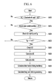
- FIG. 6 is a flowchart of a method of determining a driving tendency according to another exemplary embodiment of the present invention.
- FIG. 7 is a graph for explaining determination of a driving tendency according to another exemplary embodiment of the present invention.
- FIG. 8 is a graph showing a filter coefficient according to another exemplary embodiment of the present invention.
- FIG. 9 is a graph showing a function having an acceleration increment amount as a variable according to another exemplary embodiment of the present invention.
- FIG. 1 is a block diagram of a system of controlling shift according to an exemplary embodiment of the present invention.
- a system of controlling shift includes a data detector 100 , a controller 160 , an engine 170 and a transmission 180 .
- the data detector 100 detects data for determining a driving tendency of a driver, and the data detected by the data detector 100 is transmitted to the controller 160 .
- the data detector 100 may include a navigation device 110 , an accelerator pedal position sensor 115 , a vehicle speed sensor 120 , an acceleration sensor 125 , a timer 130 , a shift-speed sensor 135 , a steering angle sensor 140 , a brake pedal position sensor 145 , a global positioning system (GPS) and a distance sensor 155 .
- GPS global positioning system
- the navigation device 110 is a device whish informs the driver of a route to a destination.
- the navigation device 110 includes an input/output portion inputting or outputting information for guidance of the route, a current position detecting portion detecting information on a current position of the vehicle, a memory in which a map data for calculating the route and a data for guiding the route are stored, and a control portion for searching the route and performing guidance of the route.
- the navigation device 110 can provide information on a road shape such as a gradient of a road or a curvature radius of the road to the controller 160 . Therefore, it is to be understood that the navigation device 110 includes any device which can provide the information on the road shape to the controller 160 in this specification and the claims.
- the accelerator pedal position sensor 115 detects a degree with which the driver pushes an accelerator pedal. That is, the accelerator pedal position sensor 115 detects the data related to driver's acceleration will. If the accelerator pedal is pushed completely an accelerator pedal position is 100%, and if the accelerator pedal is not pushed the accelerator pedal position is 0%.
- the vehicle speed sensor 120 detects a vehicle speed, and is mounted at a wheel of the vehicle. On the contrary, the vehicle speed may be calculated based on a GPS signal received by the GPS 150 .
- a target shift-speed may be calculated by using a shift pattern based on the signal of the accelerator pedal position sensor 115 and the signal of the vehicle speed sensor 120 , and the shift to the target shift-speed is controlled. That is, hydraulic pressure supplied to a plurality of friction elements or released from the plurality of friction elements is controlled in an automatic transmission provided with a plurality of planetary gear sets and the plurality of friction elements. In addition, current applied to a plurality of synchronizer devices and actuators is controlled in a double clutch transmission.
- an engine torque may be calculated based on the signal of the accelerator pedal position sensor 115 and the target shift-speed, and the engine 30 is controlled according to the calculated engine torque.
- the acceleration sensor 125 detects a vehicle acceleration.
- the acceleration sensor 125 may be mounted in addition to the vehicle speed sensor 120 and may directly detects the vehicle acceleration, or the vehicle acceleration may be calculated by differentiating the vehicle speed detected by the vehicle speed sensor 120 .
- the timer 130 detects an elapsed time after a particular time.
- the particular time may be a time at which the accelerator pedal position reaches a predetermined position value while the vehicle is coasting.
- the shift-speed sensor 135 detects a shift-speed that is currently engaged.
- the steering angle sensor 140 detects a steering angle of the vehicle. That is, the steering angle sensor 140 detects a direction to which the vehicle runs.
- the brake pedal position sensor 145 detects whether a brake pedal is pushed or not. That is, the brake pedal position sensor 145 as well as the accelerator pedal position sensor 115 detects the driver's acceleration will.
- the GPS 150 receives a signal transmitted from a GPS satellite and transmits a signal corresponding thereto to the navigation device 110 .
- the distance sensor 155 detects a distance between the vehicle of the driver and a preceding vehicle.
- Various sensors such as an ultrasonic wave sensor and an infrared sensor may be used as the distance sensor 155 .
- the controller 160 determines the driving tendency of the driver based on the data detected by the data detector 100 .
- the controller 160 may be realized by one or more processors activated by a predetermined program, and the predetermined program may be programmed to perform each step of a method of determining driving tendency according to an exemplary embodiment of the present invention.
- the controller 160 includes a short term driving tendency index calculator, a memory and a long term driving tendency index calculator.
- the short term driving tendency index calculator determines the short term driving tendency of the driver for a comparatively short time based on the data detected by the data detector 100 . That is, the short term driving tendency index calculator determines the driving tendency of the driver, for example, during a current driving or for a predetermined time in the current driving. The short term driving tendency of the driver may be determined based on how well one or more assumptions related to the driving tendency of the driver are satisfied, and fuzzy control theory may be used to determine the short term driving tendency of the driver. The short term driving tendency of the driver determined by the short term driving tendency index calculator is calculated as a short term driving tendency index, and the short term driving tendency index is transmitted to and is stored in the memory.
- the memory stores the short term driving tendency index calculated by the short term driving tendency index calculator.
- the long term driving tendency index calculator determines the long term driving tendency of the driver from a plurality of the short term driving tendency indexes stored in the memory.
- the long term driving tendency of the driver determined by the long term driving tendency index calculator is calculated as a long term driving tendency index.
- the controller 160 can determine a condition of a road on which the vehicle runs currently based on the data detected by the data detector 100 .
- the road condition includes a specific road state such as an icy road, a slippery road, a rough road and an unpaved road, a specific road shape such as a curve road and an inclined road, and a congested degree. If the road condition shows the specific road state, the specific road shape or the congested road, it is general that the vehicle runs not according to the driving tendency of the driver but according to the road condition. Therefore, the driving tendency of the driver can be precisely determined by not calculating the short term driving tendency of the driver under the specific road condition.
- the short term driving tendency of the driver may be calculated under the specific road condition.
- a strong filter is applied to the short term driving tendency of the driver calculated under the specific road condition.
- the controller 160 controls the engine 170 or the transmission 180 according to the long term driving tendency index. That is, the controller 160 may change a shift pattern, engaging feeling to the target shift-speed, an engine torque map and/or an engine torque filter according to the long term driving tendency index.
- a driving of the engine 170 is controlled to an optimal driving point according to the control of the controller 160 .
- a shift ratio of the transmission 180 is controlled according to the control of the controller 160 .
- the transmission 180 delivers the engine torque to the driving wheel to drive the vehicle.
- FIG. 2 is a flowchart of a method of determining a driving tendency according to an exemplary embodiment of the present invention
- FIG. 3 is a graph for explaining determination of a driving tendency according to an exemplary embodiment of the present invention
- FIG. 4 is a graph showing a reference speed increment amount according to an exemplary embodiment of the present invention
- FIG. 5 is a graph showing a function having an elapsed time as a variable according to an exemplary embodiment of the present invention.
- the controller 160 determines whether a gradient of a road is within a predetermined rage at step S 210 . In detail, if the gradient of the road is greater than a first predetermined gradient ⁇ A 1 and less than a second predetermined gradient A 2 , the controller 160 may determine that the vehicle runs on a flat road.
- the vehicle runs not according to the driving tendency of the driver but according to the gradient of the road. Therefore, if the gradient of the road is not within the predetermined range, the driving tendency of the driver can be precisely determined by not calculating the short term driving tendency index.
- the controller 160 determines whether the accelerator pedal position APS increases from 0 to a predetermined position value X 1 at step S 215 . That is, the controller 160 determines the short term driving tendency of the driver if the driver pushes the accelerator pedal while the vehicle is coasting.
- the predetermined position value X 1 may be set to a value in which a person of an ordinary skill in the art preferably determines.
- the controller 160 finishes the method of determining the driving tendency according to the exemplary embodiment of the present invention.
- the controller 160 checks a vehicle speed Vs 1 at a time at which the accelerator pedal position APS reaches the predetermined position value X 1 , and then counts an elapsed time Tvs after the accelerator pedal position APS reaches the predetermined position value X 1 at step S 220 .
- the controller 160 determines whether the vehicle speed Vs increases to a predetermined speed value Vs 2 at step S 225 .
- the controller 160 may calculate the predetermined speed value Vs 2 by adding a reference speed increment amount dVs to the vehicle speed Vs 1 .
- the reference speed increment amount dVs may be determined a value that decreases as the vehicle speed Vs increases. That is, the reference speed increment amount dVs may be set to be sensitive to an increase of the vehicle speed Vs when the vehicle runs at a high speed.
- the controller 160 finishes the method of determining the driving tendency according to an exemplary embodiment of the present invention.
- the controller 160 checks the elapsed time Tvs from a time at which the accelerator pedal position APS reaches the predetermined position value X 1 to a time at which the vehicle speed Vs reaches the predetermined speed value Vs 2 at step S 230 .
- the controller 160 compares the elapsed time Tvs with a determination limit time T_limit at step S 235 . That is, the controller 160 determines whether the vehicle speed Vs reaches the predetermined speed value Vs 2 within the determination limit time T_limit.
- the determination limit time T_limit may be set to a value in which a person of an ordinary skill in the art preferably determines.
- the controller 160 finishes the method of determining the driving tendency according to an exemplary embodiment of the present invention. If the elapsed time Tvs is greater than or equal to the determination limit time T_limit, the elapsed time Tvs is not a valid value for determining the short term driving tendency. Therefore, if the elapsed time Tvs is greater than or equal to the determination limit time T_limit, the driving tendency of the driver can be precisely determined by not calculating the short term driving tendency index.
- the controller 160 calculates the short term driving tendency based on the elapsed time Tvs and a function having the elapsed time as a variable (referring to FIG. 5 ) at step S 240 .
- x-axis represents the elapsed time Tvs
- y-axis represents the short term driving tendency index
- the short term driving tendency changes according to the elapsed time Tvs.
- the longer the elapsed time Tvs the more the driver has the mild driving tendency.
- the controller 160 may calculate the long term driving tendency index by averaging the short term driving tendency indexes for a predetermined time at step S 245 .
- FIG. 6 is a flowchart of a method of determining a driving tendency according to another exemplary embodiment of the present invention
- FIG. 7 is a graph for explaining determination of a driving tendency according to another exemplary embodiment of the present invention
- FIG. 8 is a graph showing a filter coefficient according to another exemplary embodiment of the present invention
- FIG. 9 is a graph showing a function having an acceleration increment amount as a variable according to another exemplary embodiment of the present invention.
- the controller 160 determines whether the gradient of the road is within the predetermined range at step S 610 . In detail, if the gradient of the road is greater than the first predetermined gradient ⁇ A 1 % and less than a second predetermined gradient A 2 %, the controller 160 may determine that the vehicle runs on a flat road.
- the driving tendency of the driver can be precisely determined by not calculating the short term driving tendency index.
- the controller 160 determines whether the accelerator pedal position APS increases from 0 to a predetermined position value X 1 at step S 615 . That is, the controller 160 determines the short term driving tendency of the driver if the driver pushes the accelerator pedal while the vehicle is coasting.
- the controller 160 finishes the method of determining the driving tendency according to the exemplary embodiment of the present invention.
- the controller 160 checks a vehicle acceleration G 1 at a time at which the accelerator pedal position APS reaches the predetermined position value X 1 , and then counts an elapsed time Tg after the accelerator pedal position APS reaches the predetermined position value X 1 at step S 620 .
- the controller 160 determines whether the elapsed time Tg reaches a predetermined time T_ref at step S 625 .
- the predetermined time Tg may be set to a value in which a person of an ordinary skill in the art preferably determines.
- the controller 160 checks a vehicle acceleration G 2 at a time at which the elapsed time Tg reaches the predetermined time T_ref at step S 630 .
- the controller 160 calculates an acceleration increment amount dG by subtracting the vehicle acceleration G 1 from the vehicle acceleration G 2 at step S 635 .
- the controller 160 may calculates a corrected acceleration increment amount dGc by correcting the acceleration increment amount dG at step S 640 .
- the filter coefficient k may be determined a value that increases as the vehicle speed Vs increases. That is, the corrected acceleration increment amount dGc may be set to be less sensitive to an increase of the vehicle speed Vs when the vehicle runs at a low speed and be set to be sensitive to the increase of the vehicle speed Vs when the vehicle runs at a high speed.
- the controller 160 calculates the short term driving tendency based on the corrected acceleration increment amount dGc and a function having the corrected acceleration increment amount dGc as a variable (referring FIG. 9 ) at step S 650 .
- x-axis represents the corrected acceleration increment amount dGc
- y-axis represents the short term driving tendency index.
- the short term driving tendency changes according to the corrected acceleration increment amount dGc.
- the closer to 100% the short term driving tendency index is, the more the driver has a sporty driving tendency (often increases speed quickly) in FIG. 5 . That is, the lower the corrected acceleration increment amount dGc, the more the driver has the mild driving tendency.
- the higher the corrected acceleration increment amount the more the driver has the sporty driving tendency.
- the controller 160 may calculate the long term driving tendency index by averaging the short term driving tendency indexes for a predetermined time at step S 655 .
- the short term driving tendency of the driver can be determined precisely according to an exemplary embodiment of the present invention. Therefore, a will of the driver can be reflected on the shift precisely.
Landscapes
- Engineering & Computer Science (AREA)
- Transportation (AREA)
- Mechanical Engineering (AREA)
- Automation & Control Theory (AREA)
- Physics & Mathematics (AREA)
- Mathematical Physics (AREA)
- Chemical & Material Sciences (AREA)
- Combustion & Propulsion (AREA)
- Human Computer Interaction (AREA)
- Control Of Transmission Device (AREA)
- Control Of Driving Devices And Active Controlling Of Vehicle (AREA)
Applications Claiming Priority (2)
| Application Number | Priority Date | Filing Date | Title |
|---|---|---|---|
| KR10-2014-0103465 | 2014-08-11 | ||
| KR1020140103465A KR101575277B1 (ko) | 2014-08-11 | 2014-08-11 | 운전자의 운전 성향 판단 장치 및 방법 |
Publications (2)
| Publication Number | Publication Date |
|---|---|
| US20160039425A1 US20160039425A1 (en) | 2016-02-11 |
| US10173688B2 true US10173688B2 (en) | 2019-01-08 |
Family
ID=54872545
Family Applications (1)
| Application Number | Title | Priority Date | Filing Date |
|---|---|---|---|
| US14/555,321 Active 2036-10-01 US10173688B2 (en) | 2014-08-11 | 2014-11-26 | Method of determining driving tendency and system of controlling shift using the same |
Country Status (4)
| Country | Link |
|---|---|
| US (1) | US10173688B2 (zh) |
| KR (1) | KR101575277B1 (zh) |
| CN (1) | CN105774812B (zh) |
| DE (1) | DE102014117792B4 (zh) |
Families Citing this family (5)
| Publication number | Priority date | Publication date | Assignee | Title |
|---|---|---|---|---|
| KR101601134B1 (ko) * | 2014-09-22 | 2016-03-08 | 현대자동차주식회사 | 운전자의 발진 성향을 판단하는 장치 및 방법 |
| KR101822907B1 (ko) * | 2016-08-16 | 2018-01-30 | 엠텍비젼 주식회사 | 차속 산출 방법 및 장치와, 차속 산출 장치를 구비한 운전자 상태 감시 시스템 |
| KR102602917B1 (ko) | 2016-12-14 | 2023-11-23 | 현대자동차주식회사 | 차량 현가장치 제어방법 |
| CN110171428B (zh) * | 2019-05-27 | 2020-11-03 | 威睿电动汽车技术(宁波)有限公司 | 驾驶状态评估方法、装置、设备及存储介质 |
| KR20220000434A (ko) * | 2020-06-25 | 2022-01-04 | 현대모비스 주식회사 | 군집주행 제어방법 및 시스템 |
Citations (10)
| Publication number | Priority date | Publication date | Assignee | Title |
|---|---|---|---|---|
| US5152192A (en) | 1991-10-15 | 1992-10-06 | General Motors Corporation | Dynamic shift control for an automatic transmission |
| JP3446438B2 (ja) | 1996-01-04 | 2003-09-16 | 日産自動車株式会社 | 自動変速機の変速制御方法 |
| JP2005178534A (ja) | 2003-12-18 | 2005-07-07 | Nissan Motor Co Ltd | 車線逸脱防止装置 |
| JP2007148917A (ja) | 2005-11-29 | 2007-06-14 | Aisin Aw Co Ltd | 運転支援装置 |
| CN101038181A (zh) | 2006-03-15 | 2007-09-19 | 日产自动车株式会社 | 车辆的弯曲倾向检测装置及车辆动作响应控制装置 |
| KR20090014551A (ko) | 2007-08-06 | 2009-02-11 | 현대자동차주식회사 | 차량의 실시간 운전지원시스템 및 그 방법 |
| KR20090070041A (ko) | 2007-12-26 | 2009-07-01 | 주식회사 만도 | 운전자의 운전패턴을 분석하기 위한 방법 및 장치 |
| KR20110129145A (ko) | 2010-05-25 | 2011-12-01 | 현대자동차주식회사 | 안전 운전 시스템 |
| US20120029801A1 (en) | 2010-08-02 | 2012-02-02 | Denso Corporation | Driving characteristics detector and route search device |
| CN103221665A (zh) | 2010-11-26 | 2013-07-24 | 丰田自动车株式会社 | 驾驶支持系统和驾驶支持管理设备 |
Family Cites Families (5)
| Publication number | Priority date | Publication date | Assignee | Title |
|---|---|---|---|---|
| KR20140103465A (ko) | 2013-02-18 | 2014-08-27 | 손승남 | 커피박으로부터 유지류를 추출하는 방법 |
| KR101461878B1 (ko) | 2013-03-18 | 2014-11-14 | 현대자동차 주식회사 | 운전자의 장기 운전 성향을 판단하는 장치 및 방법 |
| KR101518891B1 (ko) | 2013-05-31 | 2015-05-12 | 현대자동차 주식회사 | 차량용 변속 제어 장치 및 방법 |
| KR101542957B1 (ko) | 2013-06-07 | 2015-08-10 | 현대자동차 주식회사 | 단기 운전성향 판정 가변 제어 장치 및 그 방법 |
| KR101500361B1 (ko) | 2013-06-07 | 2015-03-10 | 현대자동차 주식회사 | 단기 운전성향 판정 장치 및 그 방법 |
-
2014
- 2014-08-11 KR KR1020140103465A patent/KR101575277B1/ko active IP Right Grant
- 2014-11-26 US US14/555,321 patent/US10173688B2/en active Active
- 2014-12-03 DE DE102014117792.4A patent/DE102014117792B4/de active Active
- 2014-12-26 CN CN201410831866.7A patent/CN105774812B/zh active Active
Patent Citations (11)
| Publication number | Priority date | Publication date | Assignee | Title |
|---|---|---|---|---|
| US5152192A (en) | 1991-10-15 | 1992-10-06 | General Motors Corporation | Dynamic shift control for an automatic transmission |
| JP3446438B2 (ja) | 1996-01-04 | 2003-09-16 | 日産自動車株式会社 | 自動変速機の変速制御方法 |
| JP2005178534A (ja) | 2003-12-18 | 2005-07-07 | Nissan Motor Co Ltd | 車線逸脱防止装置 |
| JP2007148917A (ja) | 2005-11-29 | 2007-06-14 | Aisin Aw Co Ltd | 運転支援装置 |
| CN101038181A (zh) | 2006-03-15 | 2007-09-19 | 日产自动车株式会社 | 车辆的弯曲倾向检测装置及车辆动作响应控制装置 |
| KR20090014551A (ko) | 2007-08-06 | 2009-02-11 | 현대자동차주식회사 | 차량의 실시간 운전지원시스템 및 그 방법 |
| KR20090070041A (ko) | 2007-12-26 | 2009-07-01 | 주식회사 만도 | 운전자의 운전패턴을 분석하기 위한 방법 및 장치 |
| KR20110129145A (ko) | 2010-05-25 | 2011-12-01 | 현대자동차주식회사 | 안전 운전 시스템 |
| US20120029801A1 (en) | 2010-08-02 | 2012-02-02 | Denso Corporation | Driving characteristics detector and route search device |
| JP2012033107A (ja) | 2010-08-02 | 2012-02-16 | Denso Corp | 運転特性特定装置および経路探索装置 |
| CN103221665A (zh) | 2010-11-26 | 2013-07-24 | 丰田自动车株式会社 | 驾驶支持系统和驾驶支持管理设备 |
Also Published As
| Publication number | Publication date |
|---|---|
| DE102014117792A1 (de) | 2016-02-11 |
| US20160039425A1 (en) | 2016-02-11 |
| CN105774812B (zh) | 2019-06-18 |
| CN105774812A (zh) | 2016-07-20 |
| KR101575277B1 (ko) | 2015-12-07 |
| DE102014117792B4 (de) | 2021-11-04 |
Similar Documents
| Publication | Publication Date | Title |
|---|---|---|
| US9242652B2 (en) | Apparatus and method for determining short-term driving tendency of driver | |
| US9193357B2 (en) | System and method of determining long term driving tendency of driver | |
| US9324029B2 (en) | Method of determining a driving tendency, and controlling shift according to fuzzy rules | |
| US9303759B2 (en) | Method and system of controlling shift for vehicle | |
| US8965644B2 (en) | System and method of controlling shifting for vehicle | |
| US10173688B2 (en) | Method of determining driving tendency and system of controlling shift using the same | |
| US9376120B2 (en) | System and method of controlling starting of vehicle | |
| US9062762B2 (en) | Method for controlling shift of automatic transmission in vehicle | |
| US9145968B2 (en) | Device and method for controlling shift in vehicle | |
| US9387858B2 (en) | System and method of controlling shift for vehicle | |
| US20140358323A1 (en) | Apparatus and method for determining short-term driving tendency of driver | |
| US8914207B1 (en) | System and method of controlling shift for vehicle | |
| US20160272213A1 (en) | Driving force control system for vehicle | |
| US9446754B2 (en) | System and method of controlling starting of vehicle | |
| US10190677B2 (en) | System and method for determining starting tendency of driver | |
| JP6772745B2 (ja) | 省燃費制御装置及び省燃費制御方法 |
Legal Events
| Date | Code | Title | Description |
|---|---|---|---|
| AS | Assignment |
Owner name: HYUNDAI MOTOR COMPANY, KOREA, REPUBLIC OF Free format text: ASSIGNMENT OF ASSIGNORS INTEREST;ASSIGNOR:JEON, BYEONGWOOK;REEL/FRAME:034272/0947 Effective date: 20141125 Owner name: KIA MOTORS CORPORATION, KOREA, REPUBLIC OF Free format text: ASSIGNMENT OF ASSIGNORS INTEREST;ASSIGNOR:JEON, BYEONGWOOK;REEL/FRAME:034272/0947 Effective date: 20141125 |
|
| STCF | Information on status: patent grant |
Free format text: PATENTED CASE |
|
| MAFP | Maintenance fee payment |
Free format text: PAYMENT OF MAINTENANCE FEE, 4TH YEAR, LARGE ENTITY (ORIGINAL EVENT CODE: M1551); ENTITY STATUS OF PATENT OWNER: LARGE ENTITY Year of fee payment: 4 |