US10105820B1 - Superabrasive elements including coatings and methods for removing interstitial materials from superabrasive elements - Google Patents
Superabrasive elements including coatings and methods for removing interstitial materials from superabrasive elements Download PDFInfo
- Publication number
- US10105820B1 US10105820B1 US14/588,777 US201514588777A US10105820B1 US 10105820 B1 US10105820 B1 US 10105820B1 US 201514588777 A US201514588777 A US 201514588777A US 10105820 B1 US10105820 B1 US 10105820B1
- Authority
- US
- United States
- Prior art keywords
- polycrystalline diamond
- vapor deposition
- diamond element
- coating
- chemical vapor
- Prior art date
- Legal status (The legal status is an assumption and is not a legal conclusion. Google has not performed a legal analysis and makes no representation as to the accuracy of the status listed.)
- Active, expires
Links
Images


Classifications
-
- B—PERFORMING OPERATIONS; TRANSPORTING
- B24—GRINDING; POLISHING
- B24D—TOOLS FOR GRINDING, BUFFING OR SHARPENING
- B24D3/00—Physical features of abrasive bodies, or sheets, e.g. abrasive surfaces of special nature; Abrasive bodies or sheets characterised by their constituents
- B24D3/005—Physical features of abrasive bodies, or sheets, e.g. abrasive surfaces of special nature; Abrasive bodies or sheets characterised by their constituents the constituent being used during pre- or after-treatment
-
- B—PERFORMING OPERATIONS; TRANSPORTING
- B24—GRINDING; POLISHING
- B24D—TOOLS FOR GRINDING, BUFFING OR SHARPENING
- B24D18/00—Manufacture of grinding tools or other grinding devices, e.g. wheels, not otherwise provided for
- B24D18/009—Tools not otherwise provided for
-
- C—CHEMISTRY; METALLURGY
- C23—COATING METALLIC MATERIAL; COATING MATERIAL WITH METALLIC MATERIAL; CHEMICAL SURFACE TREATMENT; DIFFUSION TREATMENT OF METALLIC MATERIAL; COATING BY VACUUM EVAPORATION, BY SPUTTERING, BY ION IMPLANTATION OR BY CHEMICAL VAPOUR DEPOSITION, IN GENERAL; INHIBITING CORROSION OF METALLIC MATERIAL OR INCRUSTATION IN GENERAL
- C23C—COATING METALLIC MATERIAL; COATING MATERIAL WITH METALLIC MATERIAL; SURFACE TREATMENT OF METALLIC MATERIAL BY DIFFUSION INTO THE SURFACE, BY CHEMICAL CONVERSION OR SUBSTITUTION; COATING BY VACUUM EVAPORATION, BY SPUTTERING, BY ION IMPLANTATION OR BY CHEMICAL VAPOUR DEPOSITION, IN GENERAL
- C23C14/00—Coating by vacuum evaporation, by sputtering or by ion implantation of the coating forming material
- C23C14/06—Coating by vacuum evaporation, by sputtering or by ion implantation of the coating forming material characterised by the coating material
- C23C14/0641—Nitrides
-
- C—CHEMISTRY; METALLURGY
- C23—COATING METALLIC MATERIAL; COATING MATERIAL WITH METALLIC MATERIAL; CHEMICAL SURFACE TREATMENT; DIFFUSION TREATMENT OF METALLIC MATERIAL; COATING BY VACUUM EVAPORATION, BY SPUTTERING, BY ION IMPLANTATION OR BY CHEMICAL VAPOUR DEPOSITION, IN GENERAL; INHIBITING CORROSION OF METALLIC MATERIAL OR INCRUSTATION IN GENERAL
- C23F—NON-MECHANICAL REMOVAL OF METALLIC MATERIAL FROM SURFACE; INHIBITING CORROSION OF METALLIC MATERIAL OR INCRUSTATION IN GENERAL; MULTI-STEP PROCESSES FOR SURFACE TREATMENT OF METALLIC MATERIAL INVOLVING AT LEAST ONE PROCESS PROVIDED FOR IN CLASS C23 AND AT LEAST ONE PROCESS COVERED BY SUBCLASS C21D OR C22F OR CLASS C25
- C23F1/00—Etching metallic material by chemical means
- C23F1/02—Local etching
-
- C—CHEMISTRY; METALLURGY
- C23—COATING METALLIC MATERIAL; COATING MATERIAL WITH METALLIC MATERIAL; CHEMICAL SURFACE TREATMENT; DIFFUSION TREATMENT OF METALLIC MATERIAL; COATING BY VACUUM EVAPORATION, BY SPUTTERING, BY ION IMPLANTATION OR BY CHEMICAL VAPOUR DEPOSITION, IN GENERAL; INHIBITING CORROSION OF METALLIC MATERIAL OR INCRUSTATION IN GENERAL
- C23F—NON-MECHANICAL REMOVAL OF METALLIC MATERIAL FROM SURFACE; INHIBITING CORROSION OF METALLIC MATERIAL OR INCRUSTATION IN GENERAL; MULTI-STEP PROCESSES FOR SURFACE TREATMENT OF METALLIC MATERIAL INVOLVING AT LEAST ONE PROCESS PROVIDED FOR IN CLASS C23 AND AT LEAST ONE PROCESS COVERED BY SUBCLASS C21D OR C22F OR CLASS C25
- C23F1/00—Etching metallic material by chemical means
- C23F1/10—Etching compositions
- C23F1/14—Aqueous compositions
- C23F1/16—Acidic compositions
- C23F1/28—Acidic compositions for etching iron group metals
-
- E—FIXED CONSTRUCTIONS
- E21—EARTH DRILLING; MINING
- E21B—EARTH DRILLING, e.g. DEEP DRILLING; OBTAINING OIL, GAS, WATER, SOLUBLE OR MELTABLE MATERIALS OR A SLURRY OF MINERALS FROM WELLS
- E21B10/00—Drill bits
- E21B10/46—Drill bits characterised by wear resisting parts, e.g. diamond inserts
Definitions
- PCD polycrystalline diamond
- Other types of superabrasive materials such as ceramics (e.g., cubic boron nitride, silicon carbide, and the like), are also utilized for similar applications.
- a conventional cutting element typically includes a superabrasive layer or table, such as a PCD table.
- the PCD table is formed and bonded to a substrate using an ultra-high pressure, ultra-high temperature (“HPHT”) process.
- HPHT ultra-high pressure, ultra-high temperature
- the cutting element may be brazed, press-fit, or otherwise secured into a preformed pocket, socket, or other receptacle formed in the rotary drill bit.
- the substrate may be brazed or otherwise joined to an attachment member such as a stud or a cylindrical backing.
- a rotary drill bit may include one or more PCD cutting elements affixed to a bit body of the rotary drill bit.
- a conventional bearing element typically includes a superabrasive layer or table, such as a PCD table, bonded to a substrate.
- One or more bearing elements may be mounted to a bearing rotor or stator by press-fitting, brazing, or through other suitable methods of attachment.
- bearing elements mounted to a bearing rotor have superabrasive faces configured to contact corresponding superabrasive faces of bearing elements mounted to an adjacent bearing stator.
- Superabrasive elements having a PCD table are typically fabricated by placing a cemented carbide substrate, such as a cobalt-cemented tungsten carbide substrate, into a container or cartridge with a volume of diamond particles positioned on a surface of the cemented carbide substrate. A number of such cartridges may be loaded into a HPHT press. The substrates and diamond particle volumes may then be processed under HPHT conditions in the presence of a catalyst material that causes the diamond particles to bond to one another to form a diamond table having a matrix of bonded diamond crystals.
- the catalyst material is often a metal-solvent catalyst, such as cobalt, nickel, and/or iron, that facilitates intergrowth and bonding of the diamond crystals.
- a constituent of the cemented-carbide substrate such as cobalt from a cobalt-cemented tungsten carbide substrate, liquefies and sweeps from a region adjacent to the volume of diamond particles into interstitial regions between the diamond particles during the HPHT process.
- the cobalt acts as a catalyst to facilitate the formation of bonded diamond crystals.
- a metal-solvent catalyst may be mixed with diamond particles prior to subjecting the diamond particles and substrate to the HPHT process.
- the metal-solvent catalyst may dissolve carbon from the diamond particles and portions of the diamond particles that graphitize due to the high temperatures used in the HPHT process.
- the solubility of the stable diamond phase in the metal-solvent catalyst may be lower than that of the metastable graphite phase under HPHT conditions.
- the graphite tends to dissolve into the metal-solvent catalyst and the diamond tends to deposit onto existing diamond particles to form diamond-to-diamond bonds. Accordingly, diamond grains may become mutually bonded to form a matrix of polycrystalline diamond, with interstitial regions defined between the bonded diamond grains being occupied by the metal-solvent catalyst.
- the metal-solvent catalyst may also carry tungsten and/or tungsten carbide from the substrate into the PCD layer. Following HPHT sintering, the tungsten and/or tungsten carbide may remain in interstitial regions defined between the bonded diamond grains.
- the presence of the solvent catalyst in the diamond table is believed to reduce the thermal stability of the diamond table at elevated temperatures.
- the difference in thermal expansion coefficient between the diamond grains and the solvent catalyst is believed to lead to chipping or cracking in the PCD table of a cutting element during drilling or cutting operations.
- the chipping or cracking in the PCD table may degrade the mechanical properties of the cutting element or lead to failure of the cutting element.
- diamond grains may undergo a chemical breakdown or back-conversion with the metal-solvent catalyst. Further, portions of diamond grains may transform to carbon monoxide, carbon dioxide, graphite, or combinations thereof, thereby degrading the mechanical properties of the PCD material.
- Chemical leaching is often used to remove metal-solvent catalysts, such as cobalt, from regions of a PCD article that may experience high temperatures, such as regions adjacent to the working surfaces of the PCD article.
- Conventional chemical leaching techniques often involve the use of highly concentrated and corrosive solutions, such as highly acidic solutions, to dissolve and remove metal-solvent catalysts from polycrystalline diamond materials.
- leaching solutions may also dissolve portions of a substrate to which the PCD material is attached.
- highly acidic leaching solutions may dissolve portions of a cobalt-cemented tungsten carbide substrate, causing undesired pitting and/or other corrosion of the substrate surface.
- Such a method may comprise depositing a vaporized material over a selected portion of a polycrystalline diamond element to form a protective coating (e.g., a ceramic coating) over the selected portion.
- the polycrystalline diamond element may comprise a polycrystalline diamond table.
- the method may also comprise: 1) exposing at least a portion of the polycrystalline diamond element to a leaching solution such that the leaching solution contacts an exposed surface region of the polycrystalline diamond table and at least a portion of the protective coating and 2) removing the polycrystalline diamond element from the leaching solution.
- the protective coating may be substantially impermeable to the leaching solution.
- depositing the vaporized material over the selected portion of the polycrystalline diamond element may comprise depositing the vaporized material over the selected portion by at least one of physical vapor deposition, chemical vapor deposition, and hybrid physical-chemical vapor deposition.
- the physical vapor deposition may comprise evaporative physical vapor deposition, electron beam physical vapor deposition, sputter physical vapor deposition, cathodic arc physical vapor deposition, and/or pulsed laser physical vapor deposition.
- the chemical vapor deposition may comprise atmospheric pressure chemical vapor deposition, low-pressure chemical vapor deposition, high-vacuum chemical vapor deposition, aerosol assisted chemical vapor deposition, direct liquid injection chemical vapor deposition, microwave plasma-assisted chemical vapor deposition, plasma-enhanced chemical vapor deposition, atomic layer chemical vapor deposition, metalorganic chemical vapor deposition, rapid thermal chemical vapor deposition, and/or hot wire chemical vapor deposition.
- depositing the vaporized material over the selected portion of the polycrystalline diamond element may comprise depositing the vaporized material over the selected portion by electroless deposition, spraying, and/or flame-spraying.
- Depositing the vaporized material over the selected portion of the polycrystalline diamond element may also comprise rotating the polycrystalline diamond element relative to a vaporized material source.
- the method may comprise drying the protective coating.
- the method may further comprise bonding the protective coating to the selected portion of the polycrystalline diamond element.
- the method may also comprise removing at least a portion of the protective coating from the polycrystalline diamond element.
- the method may additionally comprise surrounding at least a portion of the protective coating with a substantially inert layer
- the protective coating may have a thickness of between approximately 1 and 10 ⁇ m.
- the polycrystalline diamond element may further comprise a substrate bonded to the polycrystalline diamond table.
- the selected portion may comprise at least a portion of a surface of the polycrystalline diamond table and at least a portion of a surface of the substrate.
- the method may comprise forming a ceramic coating over a selected portion of the polycrystalline diamond element.
- the ceramic coating may comprise a nitride material and/or a carbide material (e.g., TiN, CrN, TiAlN, CrC, AlTiN, ZrN, TiCN, etc.).
- FIG. 1 is a perspective view of an exemplary superabrasive element according to at least one embodiment.
- FIG. 2 is a cross-sectional side view of an exemplary superabrasive element that is at least partially surrounded by a coating according to at least one embodiment.
- FIG. 3 is cross-sectional side view of the exemplary superabrasive element illustrated in FIG. 2 .
- FIG. 4 is a perspective view of an exemplary drill bit according to at least one embodiment.
- FIG. 5 is a top view of the exemplary drill bit illustrated in FIG. 4 .
- FIG. 6 is a partial cut-away perspective view of an exemplary thrust bearing apparatus according to at least one embodiment.
- FIG. 7 is a partial cut-away perspective view of an exemplary radial bearing apparatus according to at least one embodiment.
- FIG. 8 is a partial cut-away perspective view of an exemplary subterranean drilling system according to at least one embodiment.
- FIG. 9 is a flow diagram of an exemplary method of processing a superabrasive element according to at least one embodiment.
- FIG. 10 is a flow diagram of an exemplary method of processing a superabrasive element according to further embodiments.
- the instant disclosure is directed to superabrasive articles, such as superabrasive cutting elements and superabrasive bearing elements.
- superabrasive and “superhard” may refer to materials exhibiting a hardness exceeding a hardness of tungsten carbide.
- a superabrasive article may represent an article of manufacture, at least a portion of which may exhibit a hardness exceeding the hardness of tungsten carbide.
- the superabrasive articles disclosed herein may be used in a variety of applications, such as drilling tools (e.g., compacts, cutting elements, gage trimmers, etc.), machining equipment, bearing apparatuses, wire-drawing machinery, and other apparatuses.
- the instant disclosure is also directed to methods of processing superabrasive articles.
- FIG. 1 is a perspective view of an exemplary superabrasive element 10 according to at least one embodiment.
- superabrasive element 10 may comprise a layer or superabrasive table 14 affixed to or formed upon a substrate 12 .
- Superabrasive table 14 may be affixed to substrate 12 at interface 26 .
- Superabrasive element 10 may comprise a rear face 18 and a substrate side surface 16 formed by substrate 12 .
- Superabrasive element 10 may also comprise a superabrasive face 20 , a superabrasive side surface 22 , and a superabrasive edge 24 formed by superabrasive table 14 .
- Superabrasive edge 24 may comprise an angular or rounded edge formed at the intersection of superabrasive side surface 22 and superabrasive face 20 .
- superabrasive edge 24 may comprise a chamfered surface extending between superabrasive side surface 22 and superabrasive face 20 .
- Substrate 12 may comprise any suitable material on which superabrasive table 14 may be formed.
- substrate 12 may comprise a cemented carbide material, such as a cobalt-cemented tungsten carbide material or any other suitable material.
- substrate 12 may include a suitable metal-solvent catalyst material, such as, for example, cobalt, nickel, iron, and/or alloys thereof.
- Substrate 12 may also include any other suitable material including, without limitation, cemented carbides such as titanium carbide, niobium carbide, tantalum carbide, vanadium carbide, chromium carbide, and/or combinations of any of the preceding carbides cemented with iron, nickel, cobalt, and/or alloys thereof.
- Superabrasive table 14 may be formed of any suitable superabrasive and/or superhard material or combination of materials, including, for example PCD. According to some embodiments, superabrasive table 14 may comprise cubic boron nitride, silicon carbide, diamond, and/or mixtures or composites including one or more of the foregoing materials.
- Superabrasive table 14 may be formed using any suitable technique.
- superabrasive table 14 may comprise a PCD layer formed by subjecting a plurality of diamond particles (e.g., diamond particles having an average particle size between approximately 0.5 ⁇ m and approximately 150 ⁇ m) to a HPHT sintering process in the presence of a metal-solvent catalyst, such as cobalt, nickel, iron, and/or any other suitable group VIII element.
- a metal-solvent catalyst such as cobalt, nickel, iron, and/or any other suitable group VIII element.
- adjacent diamond crystals in a mass of diamond particles may become bonded to one another, forming a PCD table comprising bonded diamond crystals.
- diamond crystals in superabrasive table 14 may have an average grain size of approximately 20 ⁇ m or less. Further, during a HPHT sintering process, diamond grains may become bonded to an adjacent substrate 12 at interface 26 .
- superabrasive table 14 may be formed by placing diamond particles adjacent to a substrate 12 comprising cemented tungsten carbide.
- the resulting sintered PCD layer may include various interstitial materials, including, for example, cobalt, tungsten, and/or tungsten carbide.
- tungsten and/or tungsten carbide may be swept into the PCD layer from substrate 12 during HPHT sintering.
- a liquefied metal-solvent catalyst from substrate 12 e.g., cobalt from a cobalt-cemented tungsten carbide substrate
- Tungsten and/or tungsten carbide particles may also be intentionally mixed with diamond particles prior to forming superabrasive table 14 .
- FIG. 2 is a cross-sectional side view of an exemplary superabrasive element 10 that is at least partially surrounded by a coating 28 according to at least one embodiment.
- coating 28 may be disposed on at least a portion of superabrasive element 10 .
- coating 28 may be disposed on substrate 12 such that coating 28 covers substantially all exposed surface portions of substrate 12 .
- coating 28 may cover a portion of superabrasive table 14 .
- Coating 28 may comprise any material suitable for protecting substrate 12 by preventing or inhibiting corrosion of substrate 12 during leaching of superabrasive element 10 , including, without limitation, a ceramic material or other suitable coating material.
- a suitable ceramic material may include, for example, TiN, CrN, TiAlN, CrC, AlTiN, ZrN, and/or TiCN.
- Coating 28 may be coated onto portions of superabrasive element 10 using any suitable coating technique, without limitation.
- coating 28 may be coated onto portions of superabrasive element 10 using a suitable physical vapor deposition (“PVD”) process.
- PVD physical vapor deposition
- a material used to form coating 28 may be vaporized and deposited onto surface portions of superabrasive element 10 .
- suitable PVD processes include, for example, evaporative PVD, electron beam PVD, sputter PVD, cathodic arc PVD, and/or pulsed laser PVD.
- a PVD process may be conducted at relatively low temperatures of about 500° C. or less.
- superabrasive element 10 may be rotated relative to a source generating the vaporized material to obtain a relatively even or complete coating on coated portions of superabrasive element 10 .
- Coating 28 may exhibit a desired thickness.
- coating 28 may be coated onto portions of superabrasive element 10 using a suitable chemical vapor deposition (“CVD”) process.
- CVD chemical vapor deposition
- one or more volatile reagents may be vaporized and heated and portions of superabrasive element 10 may be exposed to the vaporized reagents.
- the vaporized reagents may react and/or decompose on surface portions of superabrasive element 10 , forming a coating on the surface portions.
- CVD processes include, without limitation, atmospheric pressure CVD, low-pressure CVD, high-vacuum CVD, aerosol assisted CVD, direct liquid injection CVD, microwave plasma-assisted CVD, plasma-enhanced CVD, atomic layer CVD, metalorganic CVD, rapid thermal CVD, and/or hot wire CVD.
- a CVD process may be conducted at relatively high temperatures of about 1300° C. or less.
- the CVD process may produce a relatively even coating on coated portions of superabrasive element 10 .
- a hybrid physical-chemical vapor deposition process may also be used to coat portions of superabrasive element 10 .
- at least a portion of superabrasive element 10 may be coated using an electroless deposition technique, in which coating 28 is deposited on a conductive surface portion of superabrasive element 10 .
- coating 28 may be sprayed and/or flame sprayed onto a surface of superabrasive element 10 .
- coating 28 may be dried to form a solid or relatively solid coating.
- coating 28 may be applied to superabrasive element 10 as a liquid composition, and coating 28 may be dried using any suitable drying technique, without limitation.
- coating 28 may be applied to superabrasive element 10 in such a manner that coating 28 comprises a relatively solid coating layer upon or immediately following deposition on superabrasive element 10 .
- coating 28 may be bonded and/or otherwise adhered to at least a portion of substrate 12 and/or superabrasive table 14 .
- coating 28 may be bonded to superabrasive element 10 as coating 28 is applied to at least a portion of superabrasive element 10 .
- coating 28 may be adhered to superabrasive element 10 after coating 28 is applied to at least a portion of superabrasive element 10 .
- coating 28 may be heated, dried, and/or subjected to any other suitable conditions resulting in coating 28 becoming adhered to superabrasive element 10 .
- Coating 28 may be formed to any suitable thickness.
- coating 28 may be formed to a thickness that prevents a leaching solution from coming into contact with portions of superabrasive element 10 , such as substrate 12 , during leaching of superabrasive table 14 . Accordingly, coating 28 may protect substrate 12 from pitting and other corrosion due to exposure to a leaching solution.
- Coating 28 may be formed to a thickness that facilitates suitable adhesion of coating 28 to portions of superabrasive element 10 .
- coating 28 may have a relatively even thickness on coated portions of superabrasive element 10 .
- coating 28 may have a thickness of less than approximately 6 ⁇ m.
- coating 28 may have a thickness of between approximately 1 and 10 ⁇ m. In at least one example, coating 28 may have a thickness of between approximately 2 and 3 ⁇ m.
- Coating 28 may comprise one or more layers of material.
- coating 28 may comprise multiple layers of coating material.
- the multiple layers of coating material may comprise one or more coating materials.
- various layers of material in coating 28 may comprise different materials.
- the multiple layers in coating 28 may be formed at different times.
- a first coating layer may be formed directly on at least a portion of substrate 12 and/or superabrasive table 14 .
- a second coating layer may be formed on the first coating layer.
- the first coating layer and the second coating layer may be formed of relatively the same materials.
- the first coating layer and the second coating layer may be formed of different materials.
- additional coating layers formed of relatively the same and/or different materials as the first coating layer and the second coating layer may also be formed.
- FIG. 3 is cross-sectional side view of the exemplary superabrasive element 10 illustrated in FIG. 2 according to some embodiments.
- superabrasive element 10 may be at least partially surrounded by a protective layer 30 .
- Protective layer 30 may comprise a substantially inert material.
- protective layer 30 may comprise a substantially inert cup, such as, for example, a polytetrafluoroethylene (“PTFE”) cup.
- PTFE polytetrafluoroethylene
- the inert cup may be sized to fit tightly around and cover at least a portion of substrate 12 .
- the inert cup may be configured to fit around substrate 12 that is coated with coating 28 .
- protective layer 30 may also cover at least a portion of superabrasive table 14 .
- Protective layer 30 may prevent or reduce an amount of leaching solution coming into contact with coating 28 and/or substrate 12 during leaching of superabrasive table 14 .
- a superabrasive element 10 that is at least partially coated with coating 28 and/or protective layer 30 may be exposed to a leaching solution used in leaching various materials from superabrasive table 14 .
- a corrosive leaching solution may be used to remove a metal-solvent catalyst from interstitial spaces between diamond grains in superabrasive table 14 .
- the leaching solution may comprise various solvents, acids, and/or other suitable reagents, including, without limitation, water, peroxide, nitric acid, hydrofluoric acid, and/or hydrochloric acid.
- Superabrasive element 10 may be exposed to the leaching solution for any suitable period of time. For example, superabrasive element 10 may be exposed to the leaching solution until various interstitial materials, such as, for example, a metal-solvent catalyst, are removed from superabrasive table 14 to a desired depth.
- a superabrasive element 10 that includes a protective layer 30 and a coating 28 may be exposed to a leaching solution for relatively longer periods of time and/or may be exposed to relatively stronger leaching solutions than conventional superabrasive elements.
- protective layer 30 may be removed from superabrasive element 10 .
- coating 28 may be removed from superabrasive element 10 following leaching.
- Coating 28 may be removed using any suitable material removal technique including, without limitation, CG-grinding, chemical sand blasting, and/or bead blasting.
- a chamfered cutting edge 24 (e.g., chamfered cutting edge 24 in FIG. 1 ) may be formed prior to or following leaching.
- chamfered cutting edge 24 may be formed using the same material removal technique used to remove coating 28 .
- FIGS. 4 and 5 are a perspective view and a top view, respectively, of an exemplary drill bit 42 according to at least one embodiment.
- Drill bit 42 may represent any type or form of earth-boring or drilling tool, including, for example, a rotary drill bit.
- drill bit 42 may comprise a bit body 44 having a longitudinal axis 52 .
- Bit body 44 may define a leading end structure for drilling into a subterranean formation by rotating bit body 44 about longitudinal axis 52 and applying weight to bit body 44 .
- Bit body 44 may include radially and longitudinally extending blades 46 with leading faces 48 and a threaded pin connection 50 for connecting bit body 44 to a drill string.
- At least one cutting element 58 may be coupled to bit body 44 .
- a plurality of cutting elements 58 may be coupled to blades 46 .
- Cutting elements 58 may comprise any suitable superabrasive cutting elements, without limitation.
- cutting elements 58 may be configured according to previously described superabrasive element 10 .
- each cutting element 58 may include a superabrasive table 60 , such as a PCD table, bonded to a substrate 62 .
- Circumferentially adjacent blades 46 may define so-called junk slots 54 therebetween.
- Junk slots 54 may be configured to channel debris, such as rock or formation cuttings, away from cutting elements 58 during drilling.
- Rotary drill bit 42 may also include a plurality of nozzle cavities 56 for communicating drilling fluid from the interior of rotary drill bit 42 to cutting elements 58 .
- FIGS. 6 and 7 depict an example of a rotary drill bit 42 that employs at least one cutting element 58 comprising a superabrasive table 60 fabricated and structured in accordance with the disclosed embodiments, without limitation.
- Rotary drill bit 42 may optionally represent any number of earth-boring tools or drilling tools, including, for example, core bits, roller-cone bits, fixed-cutter bits, eccentric bits, bicenter bits, reamers, reamer wings, or any other downhole tool including superabrasive cutting elements and discs, without limitation.
- superabrasive elements and discs disclosed herein may also be utilized in applications other than cutting technology.
- embodiments of superabrasive elements disclosed herein may also form all or part of heat sinks, wire dies, bearing elements, cutting elements, cutting inserts (e.g., on a roller cone type drill bit), machining inserts, or any other article of manufacture as known in the art.
- superabrasive elements and discs, as disclosed herein may be employed in any suitable article of manufacture that includes a superabrasive element, disc, or layer.
- Other examples of articles of manufacture that may incorporate superabrasive elements as disclosed herein may be found in U.S. Pat. Nos.
- a rotor and a stator may each include at least one superabrasive element according to the embodiments disclosed herein.
- a rotor and a stator may each include at least one superabrasive element according to the embodiments disclosed herein.
- U.S. Pat. Nos. 4,410,054; 4,560,014; 5,364,192; 5,368,398; and 5,480,233 disclose subterranean drilling systems that include bearing apparatuses utilizing superabrasive elements as disclosed herein.
- FIG. 6 is partial cut-away perspective view of an exemplary thrust-bearing apparatus 64 according to at least one embodiment.
- Thrust-bearing apparatus 64 may utilize any of the disclosed superabrasive element embodiments as bearing elements 70 .
- Thrust-bearing apparatus 64 may also include bearing assemblies 66 .
- Each bearing assembly 66 may include a support ring 68 fabricated from a material, such as steel, stainless steel, or any other suitable material, without limitation.
- Each support ring 68 may include a plurality of recesses 69 configured to receive corresponding bearing elements 70 .
- Each bearing element 70 may be mounted to a corresponding support ring 68 within a corresponding recess 69 by brazing, welding, press-fitting, using fasteners, or any another suitable mounting technique, without limitation.
- One or more of bearing elements 70 may be configured in accordance with any of the disclosed superabrasive element embodiments.
- each bearing element 70 may include a substrate 72 and a superabrasive table 74 comprising a PCD material.
- Each superabrasive table 74 may form a bearing surface 76 .
- Bearing surfaces 76 of one bearing assembly 66 may bear against opposing bearing surfaces 76 of a corresponding bearing assembly 66 in thrust-bearing apparatus 64 , as illustrated in FIG. 6 .
- a first bearing assembly 66 of thrust-bearing apparatus 64 may be termed a “rotor.”
- the rotor may be operably coupled to a rotational shaft.
- a second bearing assembly 66 of thrust-bearing apparatus 64 may be held substantially stationary relative to the first bearing assembly 66 and may be termed a “stator.”
- FIG. 7 is a partial cut-away perspective view of a radial bearing apparatus 78 according to another embodiment.
- Radial bearing apparatus 78 may utilize any of the disclosed superabrasive element embodiments as bearing elements 84 and 86 .
- Radial bearing apparatus 78 may include an inner race 80 positioned generally within an outer race 82 .
- Inner race 80 may include a plurality of bearing elements 84 affixed thereto, and outer race 80 may include a plurality of corresponding bearing elements 86 affixed thereto.
- One or more of bearing elements 84 and 86 may be configured in accordance with any of the superabrasive element embodiments disclosed herein.
- Inner race 80 may be positioned generally within outer race 82 .
- inner race 80 and outer race 82 may be configured such that bearing surfaces 85 defined by bearing elements 84 and bearing surfaces 87 defined by bearing elements 86 may at least partially contact one another and move relative to one another as inner race 80 and outer race 82 rotate relative to each other.
- thrust-bearing apparatus 64 and/or radial bearing apparatus 78 may be incorporated into a subterranean drilling system.
- FIG. 8 is a partial cut-away perspective view of an exemplary subterranean drilling system 88 that includes a thrust-bearing apparatus 64 according to at least one embodiment.
- the subterranean drilling system 88 may include a housing 90 enclosing a downhole drilling motor 92 (i.e., a motor, turbine, or any other suitable device capable of rotating an output shaft, without limitation) that is operably connected to an output shaft 94 .
- a downhole drilling motor 92 i.e., a motor, turbine, or any other suitable device capable of rotating an output shaft, without limitation
- the thrust-bearing apparatus 64 shown in FIG. 8 may be operably coupled to downhole drilling motor 92 .
- a rotary drill bit 96 such as a rotary drill bit configured to engage a subterranean formation and drill a borehole, may be connected to output shaft 94 .
- rotary drill bit 96 may be a roller cone bit comprising a plurality of roller cones 98 .
- rotary drill bit 96 may comprise any suitable type of rotary drill bit, such as, for example, a so-called fixed-cutter drill bit.
- pipe sections may be connected to subterranean drilling system 88 to form a drill string capable of progressively drilling the borehole to a greater depth within a subterranean formation.
- a first thrust-bearing assembly 66 in thrust-bearing apparatus 64 may be configured as a rotor that is attached to output shaft 94 and a second thrust-bearing assembly 66 in thrust-bearing apparatus 64 may be configured as a stator.
- the rotor may rotate in conjunction with output shaft 94 and the stator may remain substantially stationary relative to the rotor.
- drilling fluid may be circulated through downhole drilling motor 92 to generate torque and effect rotation of output shaft 94 and rotary drill bit 96 attached thereto so that a borehole may be drilled.
- a portion of the drilling fluid may also be used to lubricate opposing bearing surfaces of bearing elements 70 on thrust-bearing assemblies 66 .
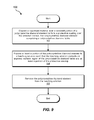
- FIG. 9 illustrates an exemplary method 100 of processing a polycrystalline diamond element according to at least one embodiment.
- a vaporized material may be deposited over a selected portion of a polycrystalline diamond element (e.g., superabrasive element 10 illustrated in FIG. 2 ) to form a protective coating (e.g., coating 28 illustrated in FIG. 2 ) over the selected portion.
- the polycrystalline diamond element may comprise a polycrystalline diamond table (e.g., superabrasive table 14 illustrated in FIG. 2 ).
- the polycrystalline diamond table may be bonded to a suitable substrate (e.g., substrate 12 illustrated in FIG. 2 ), such as, for example, a tungsten carbide substrate.
- the protective coating may also be formed on at least a portion of the polycrystalline diamond table and/or at least a portion of the substrate.
- the polycrystalline diamond element may be rotated relative to a vaporized material source during deposition.
- the vaporized material may be deposited over the selected portion of the polycrystalline diamond table using any suitable coating technique, including, for example, physical vapor deposition and/or chemical vapor deposition.
- the physical vapor deposition may comprise evaporative physical vapor deposition, electron beam physical vapor deposition, sputter physical vapor deposition, cathodic arc physical vapor deposition, and/or pulsed laser physical vapor deposition.
- the chemical vapor deposition may comprise atmospheric pressure chemical vapor deposition, low-pressure chemical vapor deposition, high-vacuum chemical vapor deposition, aerosol assisted chemical vapor deposition, direct liquid injection chemical vapor deposition, microwave plasma-assisted chemical vapor deposition, plasma-enhanced chemical vapor deposition, atomic layer chemical vapor deposition, metalorganic chemical vapor deposition, rapid thermal chemical vapor deposition, and/or hot wire chemical vapor deposition.
- the vaporized material may be deposited over the selected portion of the polycrystalline diamond element by electroless deposition, spraying, and/or flame-spraying.
- the protective coating may include any suitable material or combination of materials, including, for example, a ceramic material such as a nitride and/or a carbide material (e.g., TiN, CrN, TiAlN, CrC, AlTiN, ZrN, TiCN, etc.).
- a ceramic material such as a nitride and/or a carbide material (e.g., TiN, CrN, TiAlN, CrC, AlTiN, ZrN, TiCN, etc.).
- the protective coating may be bonded and/or otherwise adhered to at least a portion of the substrate and/or the polycrystalline diamond table.
- the protective coating may also be dried after it is formed over the selected portion of the polycrystalline diamond element.
- At least a portion of the substrate may also be surrounded with a substantially inert layer (e.g., protective layer 30 illustrated in FIG. 3 ).
- a substantially inert layer e.g., protective layer 30 illustrated in FIG. 3
- an inert PTFE cup may be placed around the polycrystalline diamond element so that the cup surrounds at least a portion of the substrate.
- the substantially inert layer may also surround at least a portion of the coating disposed on the polycrystalline diamond element.
- the inert layer may comprise a preformed layer of material, such as a cup, that is configured to closely surround at least a portion of the substrate, polycrystalline diamond table, and/or coating disposed on the polycrystalline diamond element.
- the inert layer may be formed such that it surrounds and/or frictionally engages an outer portion of the polycrystalline diamond element and/or coating. In some embodiments, the inert layer may be adhered to an outer portion of the polycrystalline diamond element and/or coating using, for example, an adhesive.
- the polycrystalline diamond element may be exposed to a leaching solution such that the leaching solution contacts an exposed surface region of the polycrystalline diamond table and at least a portion of the protective coating.
- the leaching solution may comprise various solvents, acids, and/or other suitable reagents, including, without limitation, water, peroxide, nitric acid, hydrofluoric acid, and/or hydrochloric acid.
- the polycrystalline diamond element may be exposed to the leaching solution in any suitable manner.
- the polycrystalline diamond element may be at least partially submerged in the leaching solution.
- the polycrystalline diamond element may be exposed to the leaching solution until the polycrystalline diamond table is leached to a sufficient depth.
- the coating may inhibit corrosion of the substrate during leaching, thereby preventing pitting of the substrate.
- the polycrystalline diamond element may be removed from the leaching solution.
- the polycrystalline diamond element may be removed from the leaching solution once the polycrystalline diamond table has been leached to a desired depth.
- the protective coating may also be removed from the substrate.
- the coating may be removed using any suitable technique including, without limitation, CG-grinding, chemically sand blasting, and/or bead blasting.
- a chamfered cutting edge may be formed on the polycrystalline diamond table following leaching.
- the chamfered cutting edge may be formed using the same technique used to remove the coating.
- FIG. 10 illustrates an exemplary method 200 of processing a polycrystalline diamond element according to some embodiments.
- a ceramic coating may be formed over a selected portion of a polycrystalline diamond element comprising a polycrystalline diamond table.
- at least a portion of the polycrystalline diamond element may be exposed to a leaching solution such that the leaching solution contacts an exposed surface region of the polycrystalline diamond table and at least a portion of the ceramic coating.
- the polycrystalline diamond element may be removed from the leaching solution.
Abstract
A method of processing a polycrystalline diamond element is disclosed. The method may include depositing a vaporized material over a selected portion of a polycrystalline diamond element to form a protective coating over the selected portion. The polycrystalline diamond element may include a polycrystalline diamond table. The method may also include exposing at least a portion of the polycrystalline diamond element to a leaching solution such that the leaching solution contacts an exposed surface region of the polycrystalline diamond table and at least a portion of the protective coating. The method may also include removing the polycrystalline diamond element from the leaching solution. The protective coating may be substantially impermeable to the leaching solution.
Description
This application is a continuation of U.S. patent application Ser. No. 12/767,717, titled “SUPERABRASIVE ELEMENTS INCLUDING CERAMIC COATINGS AND METHODS OF LEACHING CATALYSTS FROM SUPERABRASIVE ELEMENTS” and filed 26 Apr. 2010, which claims priority to U.S. Provisional Patent Application No. 61/172,976, titled “SUPERABRASIVE ELEMENTS INCLUDING COATINGS AND METHODS FOR REMOVING INTERSTITIAL MATERIALS FROM SUPERABRASIVE ELEMENTS” and filed 27 Apr. 2009, the disclosures of which are hereby incorporated, in their entirety, by these references.
Wear-resistant, superabrasive materials are traditionally utilized for a variety of mechanical applications. For example, polycrystalline diamond (“PCD”) materials are often used in drilling tools (e.g., cutting elements, gage trimmers, etc.), machining equipment, bearing apparatuses, wire-drawing machinery, and in other mechanical systems. Other types of superabrasive materials, such as ceramics (e.g., cubic boron nitride, silicon carbide, and the like), are also utilized for similar applications.
Conventional superabrasive materials have found utility as superabrasive cutting elements in rotary drill bits, such as roller cone drill bits and fixed-cutter drill bits. A conventional cutting element typically includes a superabrasive layer or table, such as a PCD table. The PCD table is formed and bonded to a substrate using an ultra-high pressure, ultra-high temperature (“HPHT”) process. The cutting element may be brazed, press-fit, or otherwise secured into a preformed pocket, socket, or other receptacle formed in the rotary drill bit. In another configuration, the substrate may be brazed or otherwise joined to an attachment member such as a stud or a cylindrical backing. Generally, a rotary drill bit may include one or more PCD cutting elements affixed to a bit body of the rotary drill bit.
Conventional superabrasive materials have also found utility as bearing elements in thrust bearing and radial bearing apparatuses. A conventional bearing element typically includes a superabrasive layer or table, such as a PCD table, bonded to a substrate. One or more bearing elements may be mounted to a bearing rotor or stator by press-fitting, brazing, or through other suitable methods of attachment. Typically, bearing elements mounted to a bearing rotor have superabrasive faces configured to contact corresponding superabrasive faces of bearing elements mounted to an adjacent bearing stator.
Superabrasive elements having a PCD table are typically fabricated by placing a cemented carbide substrate, such as a cobalt-cemented tungsten carbide substrate, into a container or cartridge with a volume of diamond particles positioned on a surface of the cemented carbide substrate. A number of such cartridges may be loaded into a HPHT press. The substrates and diamond particle volumes may then be processed under HPHT conditions in the presence of a catalyst material that causes the diamond particles to bond to one another to form a diamond table having a matrix of bonded diamond crystals. The catalyst material is often a metal-solvent catalyst, such as cobalt, nickel, and/or iron, that facilitates intergrowth and bonding of the diamond crystals.
In one conventional approach, a constituent of the cemented-carbide substrate, such as cobalt from a cobalt-cemented tungsten carbide substrate, liquefies and sweeps from a region adjacent to the volume of diamond particles into interstitial regions between the diamond particles during the HPHT process. In this example, the cobalt acts as a catalyst to facilitate the formation of bonded diamond crystals. Often, a metal-solvent catalyst may be mixed with diamond particles prior to subjecting the diamond particles and substrate to the HPHT process.
The metal-solvent catalyst may dissolve carbon from the diamond particles and portions of the diamond particles that graphitize due to the high temperatures used in the HPHT process. The solubility of the stable diamond phase in the metal-solvent catalyst may be lower than that of the metastable graphite phase under HPHT conditions. As a result of the solubility difference, the graphite tends to dissolve into the metal-solvent catalyst and the diamond tends to deposit onto existing diamond particles to form diamond-to-diamond bonds. Accordingly, diamond grains may become mutually bonded to form a matrix of polycrystalline diamond, with interstitial regions defined between the bonded diamond grains being occupied by the metal-solvent catalyst.
In addition to dissolving carbon and graphite, the metal-solvent catalyst may also carry tungsten and/or tungsten carbide from the substrate into the PCD layer. Following HPHT sintering, the tungsten and/or tungsten carbide may remain in interstitial regions defined between the bonded diamond grains.
The presence of the solvent catalyst in the diamond table is believed to reduce the thermal stability of the diamond table at elevated temperatures. For example, the difference in thermal expansion coefficient between the diamond grains and the solvent catalyst is believed to lead to chipping or cracking in the PCD table of a cutting element during drilling or cutting operations. The chipping or cracking in the PCD table may degrade the mechanical properties of the cutting element or lead to failure of the cutting element. Further, at high temperatures, diamond grains may undergo a chemical breakdown or back-conversion with the metal-solvent catalyst. Further, portions of diamond grains may transform to carbon monoxide, carbon dioxide, graphite, or combinations thereof, thereby degrading the mechanical properties of the PCD material.
Accordingly, it is desirable to remove a metal-solvent catalyst from a PCD material in situations where the PCD material may be exposed to high temperatures. Chemical leaching is often used to remove metal-solvent catalysts, such as cobalt, from regions of a PCD article that may experience high temperatures, such as regions adjacent to the working surfaces of the PCD article. Conventional chemical leaching techniques often involve the use of highly concentrated and corrosive solutions, such as highly acidic solutions, to dissolve and remove metal-solvent catalysts from polycrystalline diamond materials.
However, in addition to dissolving metal-solvent catalysts from a PCD material, leaching solutions may also dissolve portions of a substrate to which the PCD material is attached. For example, highly acidic leaching solutions may dissolve portions of a cobalt-cemented tungsten carbide substrate, causing undesired pitting and/or other corrosion of the substrate surface.
The instant disclosure is directed to methods of processing polycrystalline diamond elements. According to various embodiments, such a method may comprise depositing a vaporized material over a selected portion of a polycrystalline diamond element to form a protective coating (e.g., a ceramic coating) over the selected portion. The polycrystalline diamond element may comprise a polycrystalline diamond table. The method may also comprise: 1) exposing at least a portion of the polycrystalline diamond element to a leaching solution such that the leaching solution contacts an exposed surface region of the polycrystalline diamond table and at least a portion of the protective coating and 2) removing the polycrystalline diamond element from the leaching solution. The protective coating may be substantially impermeable to the leaching solution.
In some examples, depositing the vaporized material over the selected portion of the polycrystalline diamond element may comprise depositing the vaporized material over the selected portion by at least one of physical vapor deposition, chemical vapor deposition, and hybrid physical-chemical vapor deposition. The physical vapor deposition may comprise evaporative physical vapor deposition, electron beam physical vapor deposition, sputter physical vapor deposition, cathodic arc physical vapor deposition, and/or pulsed laser physical vapor deposition. In addition, the chemical vapor deposition may comprise atmospheric pressure chemical vapor deposition, low-pressure chemical vapor deposition, high-vacuum chemical vapor deposition, aerosol assisted chemical vapor deposition, direct liquid injection chemical vapor deposition, microwave plasma-assisted chemical vapor deposition, plasma-enhanced chemical vapor deposition, atomic layer chemical vapor deposition, metalorganic chemical vapor deposition, rapid thermal chemical vapor deposition, and/or hot wire chemical vapor deposition.
In various examples, depositing the vaporized material over the selected portion of the polycrystalline diamond element may comprise depositing the vaporized material over the selected portion by electroless deposition, spraying, and/or flame-spraying. Depositing the vaporized material over the selected portion of the polycrystalline diamond element may also comprise rotating the polycrystalline diamond element relative to a vaporized material source.
In at least one example, the method may comprise drying the protective coating. The method may further comprise bonding the protective coating to the selected portion of the polycrystalline diamond element. The method may also comprise removing at least a portion of the protective coating from the polycrystalline diamond element. The method may additionally comprise surrounding at least a portion of the protective coating with a substantially inert layer
In some examples, the protective coating may have a thickness of between approximately 1 and 10 μm. In one example, the polycrystalline diamond element may further comprise a substrate bonded to the polycrystalline diamond table. In this example, the selected portion may comprise at least a portion of a surface of the polycrystalline diamond table and at least a portion of a surface of the substrate.
In at least one embodiment, the method may comprise forming a ceramic coating over a selected portion of the polycrystalline diamond element. The ceramic coating may comprise a nitride material and/or a carbide material (e.g., TiN, CrN, TiAlN, CrC, AlTiN, ZrN, TiCN, etc.).
Features from any of the described embodiments may be used in combination with one another in accordance with the general principles described herein. These and other embodiments, features, and advantages will be more fully understood upon reading the following detailed description in conjunction with the accompanying drawings and claims.
The accompanying drawings illustrate a number of exemplary embodiments and are a part of the specification. Together with the following description, these drawings demonstrate and explain various principles of the instant disclosure.
Throughout the drawings, identical reference characters and descriptions indicate similar, but not necessarily identical, elements. While the exemplary embodiments described herein are susceptible to various modifications and alternative forms, specific embodiments have been shown by way of example in the drawings and will be described in detail herein. However, the exemplary embodiments described herein are not intended to be limited to the particular forms disclosed. Rather, the instant disclosure covers all modifications, equivalents, and alternatives falling within the scope of the appended claims.
The instant disclosure is directed to superabrasive articles, such as superabrasive cutting elements and superabrasive bearing elements. As used herein, the terms “superabrasive” and “superhard” may refer to materials exhibiting a hardness exceeding a hardness of tungsten carbide. For example, a superabrasive article may represent an article of manufacture, at least a portion of which may exhibit a hardness exceeding the hardness of tungsten carbide. The superabrasive articles disclosed herein may be used in a variety of applications, such as drilling tools (e.g., compacts, cutting elements, gage trimmers, etc.), machining equipment, bearing apparatuses, wire-drawing machinery, and other apparatuses. The instant disclosure is also directed to methods of processing superabrasive articles.
Superabrasive table 14 may be formed of any suitable superabrasive and/or superhard material or combination of materials, including, for example PCD. According to some embodiments, superabrasive table 14 may comprise cubic boron nitride, silicon carbide, diamond, and/or mixtures or composites including one or more of the foregoing materials.
Superabrasive table 14 may be formed using any suitable technique. For example, superabrasive table 14 may comprise a PCD layer formed by subjecting a plurality of diamond particles (e.g., diamond particles having an average particle size between approximately 0.5 μm and approximately 150 μm) to a HPHT sintering process in the presence of a metal-solvent catalyst, such as cobalt, nickel, iron, and/or any other suitable group VIII element. During a HPHT sintering process, adjacent diamond crystals in a mass of diamond particles may become bonded to one another, forming a PCD table comprising bonded diamond crystals. In one example, diamond crystals in superabrasive table 14 may have an average grain size of approximately 20 μm or less. Further, during a HPHT sintering process, diamond grains may become bonded to an adjacent substrate 12 at interface 26.
According to various embodiments, superabrasive table 14 may be formed by placing diamond particles adjacent to a substrate 12 comprising cemented tungsten carbide. The resulting sintered PCD layer may include various interstitial materials, including, for example, cobalt, tungsten, and/or tungsten carbide. For example, tungsten and/or tungsten carbide may be swept into the PCD layer from substrate 12 during HPHT sintering. In some examples, a liquefied metal-solvent catalyst from substrate 12 (e.g., cobalt from a cobalt-cemented tungsten carbide substrate) may dissolve and carry tungsten and/or tungsten carbide from substrate 12 into a diamond mass used to form superabrasive table 14 during HPHT sintering. Tungsten and/or tungsten carbide particles may also be intentionally mixed with diamond particles prior to forming superabrasive table 14.
A PVD process may be conducted at relatively low temperatures of about 500° C. or less. During a PVD process, superabrasive element 10 may be rotated relative to a source generating the vaporized material to obtain a relatively even or complete coating on coated portions of superabrasive element 10. Coating 28 may exhibit a desired thickness.
In some embodiments, coating 28 may be coated onto portions of superabrasive element 10 using a suitable chemical vapor deposition (“CVD”) process. In a CVD process, one or more volatile reagents may be vaporized and heated and portions of superabrasive element 10 may be exposed to the vaporized reagents. The vaporized reagents may react and/or decompose on surface portions of superabrasive element 10, forming a coating on the surface portions. Examples of suitable CVD processes include, without limitation, atmospheric pressure CVD, low-pressure CVD, high-vacuum CVD, aerosol assisted CVD, direct liquid injection CVD, microwave plasma-assisted CVD, plasma-enhanced CVD, atomic layer CVD, metalorganic CVD, rapid thermal CVD, and/or hot wire CVD.
In some examples, a CVD process may be conducted at relatively high temperatures of about 1300° C. or less. The CVD process may produce a relatively even coating on coated portions of superabrasive element 10. A hybrid physical-chemical vapor deposition process may also be used to coat portions of superabrasive element 10. In at least one embodiment, at least a portion of superabrasive element 10 may be coated using an electroless deposition technique, in which coating 28 is deposited on a conductive surface portion of superabrasive element 10. In various embodiments, coating 28 may be sprayed and/or flame sprayed onto a surface of superabrasive element 10.
In some embodiments, after coating 28 is applied to at least a portion of superabrasive element 10, coating 28 may be dried to form a solid or relatively solid coating. For example, coating 28 may be applied to superabrasive element 10 as a liquid composition, and coating 28 may be dried using any suitable drying technique, without limitation. In various examples, coating 28 may be applied to superabrasive element 10 in such a manner that coating 28 comprises a relatively solid coating layer upon or immediately following deposition on superabrasive element 10.
According to at least one embodiment, coating 28 may be bonded and/or otherwise adhered to at least a portion of substrate 12 and/or superabrasive table 14. For example, coating 28 may be bonded to superabrasive element 10 as coating 28 is applied to at least a portion of superabrasive element 10. In various embodiments, coating 28 may be adhered to superabrasive element 10 after coating 28 is applied to at least a portion of superabrasive element 10. For example, coating 28 may be heated, dried, and/or subjected to any other suitable conditions resulting in coating 28 becoming adhered to superabrasive element 10.
The inert cup may be sized to fit tightly around and cover at least a portion of substrate 12. In some embodiments, as illustrated in FIG. 3 , the inert cup may be configured to fit around substrate 12 that is coated with coating 28. In some examples, protective layer 30 may also cover at least a portion of superabrasive table 14. Protective layer 30 may prevent or reduce an amount of leaching solution coming into contact with coating 28 and/or substrate 12 during leaching of superabrasive table 14.
A superabrasive element 10 that is at least partially coated with coating 28 and/or protective layer 30 may be exposed to a leaching solution used in leaching various materials from superabrasive table 14. In at least one example, a corrosive leaching solution may be used to remove a metal-solvent catalyst from interstitial spaces between diamond grains in superabrasive table 14. According to various embodiments, the leaching solution may comprise various solvents, acids, and/or other suitable reagents, including, without limitation, water, peroxide, nitric acid, hydrofluoric acid, and/or hydrochloric acid. Superabrasive element 10 may be exposed to the leaching solution for any suitable period of time. For example, superabrasive element 10 may be exposed to the leaching solution until various interstitial materials, such as, for example, a metal-solvent catalyst, are removed from superabrasive table 14 to a desired depth.
Although small amounts of leaching solution may seep between protective layer 30 and coating 28 during leaching of superabrasive element 10, the rate of corrosion of coating 28 due to the leaching solution may be reduced in comparison with a superabrasive element 10 that does not include protective layer 30. Protective layer 30 may therefore inhibit the leaching solution from chemically corroding coating 28 and/or substrate 12. Accordingly, a superabrasive element 10 that includes a protective layer 30 and a coating 28 may be exposed to a leaching solution for relatively longer periods of time and/or may be exposed to relatively stronger leaching solutions than conventional superabrasive elements.
Following leaching of superabrasive table 14, protective layer 30 may be removed from superabrasive element 10. Further, coating 28 may be removed from superabrasive element 10 following leaching. Coating 28 may be removed using any suitable material removal technique including, without limitation, CG-grinding, chemical sand blasting, and/or bead blasting. According to various embodiments, a chamfered cutting edge 24 (e.g., chamfered cutting edge 24 in FIG. 1 ) may be formed prior to or following leaching. In at least one example, chamfered cutting edge 24 may be formed using the same material removal technique used to remove coating 28.
As illustrated in FIGS. 4 and 5 , drill bit 42 may comprise a bit body 44 having a longitudinal axis 52. Bit body 44 may define a leading end structure for drilling into a subterranean formation by rotating bit body 44 about longitudinal axis 52 and applying weight to bit body 44. Bit body 44 may include radially and longitudinally extending blades 46 with leading faces 48 and a threaded pin connection 50 for connecting bit body 44 to a drill string.
At least one cutting element 58 may be coupled to bit body 44. For example, as shown in FIGS. 4 and 5 , a plurality of cutting elements 58 may be coupled to blades 46. Cutting elements 58 may comprise any suitable superabrasive cutting elements, without limitation. In at least one embodiment, cutting elements 58 may be configured according to previously described superabrasive element 10. For example, each cutting element 58 may include a superabrasive table 60, such as a PCD table, bonded to a substrate 62.
Circumferentially adjacent blades 46 may define so-called junk slots 54 therebetween. Junk slots 54 may be configured to channel debris, such as rock or formation cuttings, away from cutting elements 58 during drilling. Rotary drill bit 42 may also include a plurality of nozzle cavities 56 for communicating drilling fluid from the interior of rotary drill bit 42 to cutting elements 58.
The superabrasive elements and discs disclosed herein may also be utilized in applications other than cutting technology. For example, embodiments of superabrasive elements disclosed herein may also form all or part of heat sinks, wire dies, bearing elements, cutting elements, cutting inserts (e.g., on a roller cone type drill bit), machining inserts, or any other article of manufacture as known in the art. Thus, superabrasive elements and discs, as disclosed herein, may be employed in any suitable article of manufacture that includes a superabrasive element, disc, or layer. Other examples of articles of manufacture that may incorporate superabrasive elements as disclosed herein may be found in U.S. Pat. Nos. 4,811,801; 4,268,276; 4,468,138; 4,738,322; 4,913,247; 5,016,718; 5,092,687; 5,120,327; 5,135,061; 5,154,245; 5,460,233; 5,544,713; and 6,793,681, the disclosure of each of which is incorporated herein, in its entirety, by this reference.
In some embodiments, a rotor and a stator, such as a rotor and a stator used in a thrust bearing apparatus, may each include at least one superabrasive element according to the embodiments disclosed herein. For example, U.S. Pat. Nos. 4,410,054; 4,560,014; 5,364,192; 5,368,398; and 5,480,233, the disclosure of each of which is incorporated herein, in its entirety, by this reference, disclose subterranean drilling systems that include bearing apparatuses utilizing superabrasive elements as disclosed herein.
Each support ring 68 may include a plurality of recesses 69 configured to receive corresponding bearing elements 70. Each bearing element 70 may be mounted to a corresponding support ring 68 within a corresponding recess 69 by brazing, welding, press-fitting, using fasteners, or any another suitable mounting technique, without limitation. One or more of bearing elements 70 may be configured in accordance with any of the disclosed superabrasive element embodiments. For example, each bearing element 70 may include a substrate 72 and a superabrasive table 74 comprising a PCD material. Each superabrasive table 74 may form a bearing surface 76.
Bearing surfaces 76 of one bearing assembly 66 may bear against opposing bearing surfaces 76 of a corresponding bearing assembly 66 in thrust-bearing apparatus 64, as illustrated in FIG. 6 . For example, a first bearing assembly 66 of thrust-bearing apparatus 64 may be termed a “rotor.” The rotor may be operably coupled to a rotational shaft. A second bearing assembly 66 of thrust-bearing apparatus 64 may be held substantially stationary relative to the first bearing assembly 66 and may be termed a “stator.”
The thrust-bearing apparatus 64 shown in FIG. 8 may be operably coupled to downhole drilling motor 92. A rotary drill bit 96, such as a rotary drill bit configured to engage a subterranean formation and drill a borehole, may be connected to output shaft 94. As illustrated in FIG. 8 , rotary drill bit 96 may be a roller cone bit comprising a plurality of roller cones 98. According to some embodiments, rotary drill bit 96 may comprise any suitable type of rotary drill bit, such as, for example, a so-called fixed-cutter drill bit. As a borehole is drilled using rotary bit 96, pipe sections may be connected to subterranean drilling system 88 to form a drill string capable of progressively drilling the borehole to a greater depth within a subterranean formation.
A first thrust-bearing assembly 66 in thrust-bearing apparatus 64 may be configured as a rotor that is attached to output shaft 94 and a second thrust-bearing assembly 66 in thrust-bearing apparatus 64 may be configured as a stator. During a drilling operation using subterranean drilling system 88, the rotor may rotate in conjunction with output shaft 94 and the stator may remain substantially stationary relative to the rotor.
According to various embodiments, drilling fluid may be circulated through downhole drilling motor 92 to generate torque and effect rotation of output shaft 94 and rotary drill bit 96 attached thereto so that a borehole may be drilled. A portion of the drilling fluid may also be used to lubricate opposing bearing surfaces of bearing elements 70 on thrust-bearing assemblies 66.
The vaporized material may be deposited over the selected portion of the polycrystalline diamond table using any suitable coating technique, including, for example, physical vapor deposition and/or chemical vapor deposition. The physical vapor deposition may comprise evaporative physical vapor deposition, electron beam physical vapor deposition, sputter physical vapor deposition, cathodic arc physical vapor deposition, and/or pulsed laser physical vapor deposition.
The chemical vapor deposition may comprise atmospheric pressure chemical vapor deposition, low-pressure chemical vapor deposition, high-vacuum chemical vapor deposition, aerosol assisted chemical vapor deposition, direct liquid injection chemical vapor deposition, microwave plasma-assisted chemical vapor deposition, plasma-enhanced chemical vapor deposition, atomic layer chemical vapor deposition, metalorganic chemical vapor deposition, rapid thermal chemical vapor deposition, and/or hot wire chemical vapor deposition. In some examples, the vaporized material may be deposited over the selected portion of the polycrystalline diamond element by electroless deposition, spraying, and/or flame-spraying.
The protective coating may include any suitable material or combination of materials, including, for example, a ceramic material such as a nitride and/or a carbide material (e.g., TiN, CrN, TiAlN, CrC, AlTiN, ZrN, TiCN, etc.). According to at least one embodiment, the protective coating may be bonded and/or otherwise adhered to at least a portion of the substrate and/or the polycrystalline diamond table. The protective coating may also be dried after it is formed over the selected portion of the polycrystalline diamond element.
At least a portion of the substrate may also be surrounded with a substantially inert layer (e.g., protective layer 30 illustrated in FIG. 3 ). For example, an inert PTFE cup may be placed around the polycrystalline diamond element so that the cup surrounds at least a portion of the substrate. The substantially inert layer may also surround at least a portion of the coating disposed on the polycrystalline diamond element. In at least one embodiment, the inert layer may comprise a preformed layer of material, such as a cup, that is configured to closely surround at least a portion of the substrate, polycrystalline diamond table, and/or coating disposed on the polycrystalline diamond element. In at least one example, the inert layer may be formed such that it surrounds and/or frictionally engages an outer portion of the polycrystalline diamond element and/or coating. In some embodiments, the inert layer may be adhered to an outer portion of the polycrystalline diamond element and/or coating using, for example, an adhesive.
At step 104, at least a portion of the polycrystalline diamond element may be exposed to a leaching solution such that the leaching solution contacts an exposed surface region of the polycrystalline diamond table and at least a portion of the protective coating. According to various embodiments, the leaching solution may comprise various solvents, acids, and/or other suitable reagents, including, without limitation, water, peroxide, nitric acid, hydrofluoric acid, and/or hydrochloric acid. The polycrystalline diamond element may be exposed to the leaching solution in any suitable manner. For example, the polycrystalline diamond element may be at least partially submerged in the leaching solution. The polycrystalline diamond element may be exposed to the leaching solution until the polycrystalline diamond table is leached to a sufficient depth. The coating may inhibit corrosion of the substrate during leaching, thereby preventing pitting of the substrate.
At step 106, the polycrystalline diamond element may be removed from the leaching solution. For example, the polycrystalline diamond element may be removed from the leaching solution once the polycrystalline diamond table has been leached to a desired depth. Once the polycrystalline diamond element has been removed from the leaching solution, the protective coating may also be removed from the substrate. The coating may be removed using any suitable technique including, without limitation, CG-grinding, chemically sand blasting, and/or bead blasting. According to various embodiments, a chamfered cutting edge may be formed on the polycrystalline diamond table following leaching. For example, the chamfered cutting edge may be formed using the same technique used to remove the coating.
The preceding description has been provided to enable others skilled in the art to best utilize various aspects of the exemplary embodiments described herein. This exemplary description is not intended to be exhaustive or to be limited to any precise form disclosed. Many modifications and variations are possible without departing from the spirit and scope of the instant disclosure. It is desired that the embodiments described herein be considered in all respects illustrative and not restrictive and that reference be made to the appended claims and their equivalents for determining the scope of the instant disclosure.
Unless otherwise noted, the terms “a” or “an,” as used in the specification and claims, are to be construed as meaning “at least one of.” In addition, for ease of use, the words “including” and “having,” as used in the specification and claims, are interchangeable with and have the same meaning as the word “comprising.”
Claims (23)
1. A method of processing a polycrystalline diamond element, comprising:
forming a protective coating over a selected portion of a polycrystalline diamond element comprising a polycrystalline diamond table having a polycrystalline diamond face, the polycrystalline diamond element comprising a rear surface and a side surface extending between the polycrystalline diamond face and the rear surface;
bonding the protective coating to the selected portion of the polycrystalline diamond element;
surrounding at least a portion of the protective coating with a protective layer;
exposing a portion of the polycrystalline diamond element extending from an open end of the protective layer to a leaching solution such that the leaching solution contacts an exposed surface region of the polycrystalline diamond table and at least a portion of the protective layer;
removing the polycrystalline diamond element from the leaching solution;
wherein:
the protective coating is substantially impermeable to the leaching solution;
the protective coating covers at least a portion of the side surface of the polycrystalline diamond element and the rear surface of the polycrystalline diamond element.
2. The method of claim 1 , wherein forming the protective coating over the selected portion of the polycrystalline diamond element comprises depositing a vaporized material over the selected portion by at least one of physical vapor deposition, chemical vapor deposition, and hybrid physical-chemical vapor deposition.
3. The method of claim 2 , wherein the physical vapor deposition comprises at least one of evaporative physical vapor deposition, electron beam physical vapor deposition, sputter physical vapor deposition, cathodic arc physical vapor deposition, and pulsed laser physical vapor deposition.
4. The method of claim 2 , wherein the chemical vapor deposition comprises at least one of atmospheric pressure chemical vapor deposition, low-pressure chemical vapor deposition, high-vacuum chemical vapor deposition, aerosol assisted chemical vapor deposition, direct liquid injection chemical vapor deposition, microwave plasma-assisted chemical vapor deposition, plasma-enhanced chemical vapor deposition, atomic layer chemical vapor deposition, metalorganic chemical vapor deposition, rapid thermal chemical vapor deposition, and hot wire chemical vapor deposition.
5. The method of claim 1 , wherein forming the protective coating over the selected portion of the polycrystalline diamond element comprises depositing the vaporized material over the selected portion by at least one of electroless deposition, spraying, and flame-spraying.
6. The method of claim 1 , wherein forming the protective coating over the selected portion of the polycrystalline diamond element comprises rotating the polycrystalline diamond element relative to a vaporized material source.
7. The method of claim 1 , further comprising removing the protective layer and at least a portion of the protective coating from the polycrystalline diamond element.
8. The method of claim 1 , wherein the protective coating has a thickness of between approximately 1 and 10 μm.
9. The method of claim 1 , wherein the protective layer comprises a substantially inert layer.
10. The method of claim 1 , wherein the protective layer abuts at least a portion of the protective coating.
11. The method of claim 1 , wherein surrounding at least the portion of the protective coating with the protective layer comprises placing, after forming the protective coating over the selected portion of the polycrystalline diamond element, the protective layer around at least a portion of the polycrystalline diamond element and at least the portion of the protective coating.
12. The method of claim 1 , wherein:
the polycrystalline diamond element further comprises a substrate bonded to the polycrystalline diamond table;
the selected portion comprises at least a portion of a surface of the polycrystalline diamond table and at least a portion of a surface of the substrate.
13. A method of processing a polycrystalline diamond element, comprising:
forming a ceramic coating over a selected portion of a polycrystalline diamond element comprising a polycrystalline diamond table having a polycrystalline diamond face, the polycrystalline diamond element comprising a rear surface and a side surface extending between the polycrystalline diamond face and the rear surface;
surrounding at least a portion of the ceramic coating with a protective layer;
exposing at least a portion of the polycrystalline diamond element to a leaching solution such that the leaching solution contacts an exposed surface region of the polycrystalline diamond table and at least a portion of the protective layer;
removing the polycrystalline diamond element from the leaching solution;
wherein the ceramic coating covers at least a portion of the side surface of the polycrystalline diamond element and substantially covers the rear surface of the polycrystalline diamond element.
14. The method of claim 13 , wherein the ceramic coating comprises at least one of a nitride material and a carbide material.
15. The method of claim 13 , wherein the ceramic coating comprises at least one of TiN, CrN, TiAlN, CrC, AlTiN, ZrN, and TiCN.
16. The method of claim 13 , wherein forming a ceramic coating over the selected portion of the polycrystalline diamond element comprises depositing a vaporized material over the selected portion of the polycrystalline diamond element.
17. The method of claim 13 , further comprising removing the protective layer and at least a portion of the ceramic coating from the polycrystalline diamond element.
18. The method of claim 13 , wherein the protective layer comprises a substantially inert layer.
19. The method of claim 13 , wherein the protective layer abuts at least a portion of the ceramic coating.
20. The method of claim 13 , wherein the surrounding at least the portion of the ceramic coating with the protective layer comprises placing a polymer cup around at least a portion of the polycrystalline diamond element and at least the portion of the ceramic coating.
21. The method of claim 1 , wherein the portion of the protective coating covering the rear surface of the polycrystalline diamond element is disposed between the rear surface of the polycrystalline diamond element and a portion of the protective layer.
22. The method of claim 1 , wherein surrounding at least the portion of the protective coating with the protective layer comprises enclosing at least the portion of the protective coating within a polymer cup.
23. The method of claim 1 , wherein the protective coating comprises a solid material.
Priority Applications (1)
| Application Number | Priority Date | Filing Date | Title |
|---|---|---|---|
| US14/588,777 US10105820B1 (en) | 2009-04-27 | 2015-01-02 | Superabrasive elements including coatings and methods for removing interstitial materials from superabrasive elements |
Applications Claiming Priority (3)
| Application Number | Priority Date | Filing Date | Title |
|---|---|---|---|
| US17297609P | 2009-04-27 | 2009-04-27 | |
| US12/767,717 US8951317B1 (en) | 2009-04-27 | 2010-04-26 | Superabrasive elements including ceramic coatings and methods of leaching catalysts from superabrasive elements |
| US14/588,777 US10105820B1 (en) | 2009-04-27 | 2015-01-02 | Superabrasive elements including coatings and methods for removing interstitial materials from superabrasive elements |
Related Parent Applications (1)
| Application Number | Title | Priority Date | Filing Date |
|---|---|---|---|
| US12/767,717 Continuation US8951317B1 (en) | 2009-04-27 | 2010-04-26 | Superabrasive elements including ceramic coatings and methods of leaching catalysts from superabrasive elements |
Publications (1)
| Publication Number | Publication Date |
|---|---|
| US10105820B1 true US10105820B1 (en) | 2018-10-23 |
Family
ID=52443571
Family Applications (2)
| Application Number | Title | Priority Date | Filing Date |
|---|---|---|---|
| US12/767,717 Active 2032-04-12 US8951317B1 (en) | 2009-04-27 | 2010-04-26 | Superabrasive elements including ceramic coatings and methods of leaching catalysts from superabrasive elements |
| US14/588,777 Active 2030-05-13 US10105820B1 (en) | 2009-04-27 | 2015-01-02 | Superabrasive elements including coatings and methods for removing interstitial materials from superabrasive elements |
Family Applications Before (1)
| Application Number | Title | Priority Date | Filing Date |
|---|---|---|---|
| US12/767,717 Active 2032-04-12 US8951317B1 (en) | 2009-04-27 | 2010-04-26 | Superabrasive elements including ceramic coatings and methods of leaching catalysts from superabrasive elements |
Country Status (1)
| Country | Link |
|---|---|
| US (2) | US8951317B1 (en) |
Cited By (1)
| Publication number | Priority date | Publication date | Assignee | Title |
|---|---|---|---|---|
| CN111515769A (en) * | 2020-05-18 | 2020-08-11 | 中国科学院上海光学精密机械研究所 | Method for polishing silicon carbide reflector by using small grinding head to assist atmosphere plasma |
Families Citing this family (5)
| Publication number | Priority date | Publication date | Assignee | Title |
|---|---|---|---|---|
| US9393674B2 (en) * | 2013-04-04 | 2016-07-19 | Smith International, Inc. | Cemented carbide composite for a downhole tool |
| US9550276B1 (en) * | 2013-06-18 | 2017-01-24 | Us Synthetic Corporation | Leaching assemblies, systems, and methods for processing superabrasive elements |
| US10723626B1 (en) | 2015-05-31 | 2020-07-28 | Us Synthetic Corporation | Leached superabrasive elements and systems, methods and assemblies for processing superabrasive materials |
| US10704334B2 (en) * | 2017-06-24 | 2020-07-07 | Wenhui Jiang | Polycrystalline diamond compact cutters having protective barrier coatings |
| CN111041448B (en) * | 2020-01-07 | 2022-05-17 | 汇专科技集团股份有限公司 | Method for preparing diamond coating on surface of cobalt-containing hard alloy and tool and die with diamond coating |
Citations (179)
| Publication number | Priority date | Publication date | Assignee | Title |
|---|---|---|---|---|
| US3136615A (en) | 1960-10-03 | 1964-06-09 | Gen Electric | Compact of abrasive crystalline material with boron carbide bonding medium |
| US3141746A (en) | 1960-10-03 | 1964-07-21 | Gen Electric | Diamond compact abrasive |
| US3233988A (en) | 1964-05-19 | 1966-02-08 | Gen Electric | Cubic boron nitride compact and method for its production |
| US3579057A (en) * | 1969-08-18 | 1971-05-18 | Rca Corp | Method of making a semiconductor article and the article produced thereby |
| US3745623A (en) | 1971-12-27 | 1973-07-17 | Gen Electric | Diamond tools for machining |
| GB1349385A (en) | 1970-04-08 | 1974-04-03 | Gen Electric | Diamond tools for machining |
| US4108614A (en) | 1976-04-14 | 1978-08-22 | Robert Dennis Mitchell | Zirconium layer for bonding diamond compact to cemented carbide backing |
| US4151686A (en) | 1978-01-09 | 1979-05-01 | General Electric Company | Silicon carbide and silicon bonded polycrystalline diamond body and method of making it |
| US4224380A (en) | 1978-03-28 | 1980-09-23 | General Electric Company | Temperature resistant abrasive compact and method for making same |
| GB2048927A (en) | 1979-03-19 | 1980-12-17 | De Beers Ind Diamond | Abrasive compacts |
| US4255165A (en) | 1978-12-22 | 1981-03-10 | General Electric Company | Composite compact of interleaved polycrystalline particles and cemented carbide masses |
| US4268276A (en) | 1978-04-24 | 1981-05-19 | General Electric Company | Compact of boron-doped diamond and method for making same |
| US4288248A (en) | 1978-03-28 | 1981-09-08 | General Electric Company | Temperature resistant abrasive compact and method for making same |
| US4303442A (en) | 1978-08-26 | 1981-12-01 | Sumitomo Electric Industries, Ltd. | Diamond sintered body and the method for producing the same |
| US4311490A (en) | 1980-12-22 | 1982-01-19 | General Electric Company | Diamond and cubic boron nitride abrasive compacts using size selective abrasive particle layers |
| US4373593A (en) | 1979-03-16 | 1983-02-15 | Christensen, Inc. | Drill bit |
| US4387287A (en) | 1978-06-29 | 1983-06-07 | Diamond S.A. | Method for a shaping of polycrystalline synthetic diamond |
| US4412980A (en) | 1979-06-11 | 1983-11-01 | Sumitomo Electric Industries, Ltd. | Method for producing a diamond sintered compact |
| JPS5935066A (en) | 1982-08-18 | 1984-02-25 | 住友電気工業株式会社 | Diamond sintered body for tool and manufacture |
| US4481016A (en) | 1978-08-18 | 1984-11-06 | Campbell Nicoll A D | Method of making tool inserts and drill bits |
| US4486286A (en) | 1982-09-28 | 1984-12-04 | Nerken Research Corp. | Method of depositing a carbon film on a substrate and products obtained thereby |
| JPS59219500A (en) | 1983-05-24 | 1984-12-10 | Sumitomo Electric Ind Ltd | Diamond sintered body and treatment thereof |
| US4504519A (en) | 1981-10-21 | 1985-03-12 | Rca Corporation | Diamond-like film and process for producing same |
| US4522633A (en) | 1982-08-05 | 1985-06-11 | Dyer Henry B | Abrasive bodies |
| US4525179A (en) | 1981-07-27 | 1985-06-25 | General Electric Company | Process for making diamond and cubic boron nitride compacts |
| US4534773A (en) | 1983-01-10 | 1985-08-13 | Cornelius Phaal | Abrasive product and method for manufacturing |
| US4556403A (en) | 1983-02-08 | 1985-12-03 | Almond Eric A | Diamond abrasive products |
| US4560014A (en) | 1982-04-05 | 1985-12-24 | Smith International, Inc. | Thrust bearing assembly for a downhole drill motor |
| US4570726A (en) | 1982-10-06 | 1986-02-18 | Megadiamond Industries, Inc. | Curved contact portion on engaging elements for rotary type drag bits |
| US4572722A (en) | 1982-10-21 | 1986-02-25 | Dyer Henry B | Abrasive compacts |
| JPS6167740A (en) | 1984-09-08 | 1986-04-07 | Sumitomo Electric Ind Ltd | Diamond sintered body for tools and its manufacture |
| JPS61125739A (en) | 1984-11-21 | 1986-06-13 | Sumitomo Electric Ind Ltd | Diamond sintered article for tool and manufacture thereof |
| US4604106A (en) | 1984-04-16 | 1986-08-05 | Smith International Inc. | Composite polycrystalline diamond compact |
| US4605343A (en) | 1984-09-20 | 1986-08-12 | General Electric Company | Sintered polycrystalline diamond compact construction with integral heat sink |
| US4606738A (en) | 1981-04-01 | 1986-08-19 | General Electric Company | Randomly-oriented polycrystalline silicon carbide coatings for abrasive grains |
| EP0196777A1 (en) | 1985-03-01 | 1986-10-08 | Reed Tool Company Limited | Improvements in or relating to cutting elements for rotary drill bits |
| US4621031A (en) | 1984-11-16 | 1986-11-04 | Dresser Industries, Inc. | Composite material bonded by an amorphous metal, and preparation thereof |
| US4636253A (en) | 1984-09-08 | 1987-01-13 | Sumitomo Electric Industries, Ltd. | Diamond sintered body for tools and method of manufacturing same |
| US4645977A (en) | 1984-08-31 | 1987-02-24 | Matsushita Electric Industrial Co., Ltd. | Plasma CVD apparatus and method for forming a diamond like carbon film |
| US4662348A (en) | 1985-06-20 | 1987-05-05 | Megadiamond, Inc. | Burnishing diamond |
| US4664705A (en) | 1985-07-30 | 1987-05-12 | Sii Megadiamond, Inc. | Infiltrated thermally stable polycrystalline diamond |
| US4670025A (en) | 1984-08-13 | 1987-06-02 | Pipkin Noel J | Thermally stable diamond compacts |
| US4707384A (en) | 1984-06-27 | 1987-11-17 | Santrade Limited | Method for making a composite body coated with one or more layers of inorganic materials including CVD diamond |
| US4726718A (en) | 1984-03-26 | 1988-02-23 | Eastman Christensen Co. | Multi-component cutting element using triangular, rectangular and higher order polyhedral-shaped polycrystalline diamond disks |
| JPS6355161A (en) | 1987-07-17 | 1988-03-09 | 住友電気工業株式会社 | Manufacture of industrial diamond sintered body |
| US4731296A (en) | 1986-07-03 | 1988-03-15 | Mitsubishi Kinzoku Kabushiki Kaisha | Diamond-coated tungsten carbide-base sintered hard alloy material for insert of a cutting tool |
| JPS6369971A (en) | 1986-09-11 | 1988-03-30 | Toshiba Tungaloy Co Ltd | Production of diamond coated sintered body |
| US4766040A (en) | 1987-06-26 | 1988-08-23 | Sandvik Aktiebolag | Temperature resistant abrasive polycrystalline diamond bodies |
| US4776861A (en) | 1983-08-29 | 1988-10-11 | General Electric Company | Polycrystalline abrasive grit |
| US4784023A (en) | 1985-12-05 | 1988-11-15 | Diamant Boart-Stratabit (Usa) Inc. | Cutting element having composite formed of cemented carbide substrate and diamond layer and method of making same |
| US4792001A (en) | 1986-03-27 | 1988-12-20 | Shell Oil Company | Rotary drill bit |
| US4793828A (en) | 1984-03-30 | 1988-12-27 | Tenon Limited | Abrasive products |
| US4797241A (en) | 1985-05-20 | 1989-01-10 | Sii Megadiamond | Method for producing multiple polycrystalline bodies |
| EP0300699A2 (en) | 1987-07-24 | 1989-01-25 | Smith International, Inc. | Bearings for rock bits |
| US4802539A (en) | 1984-12-21 | 1989-02-07 | Smith International, Inc. | Polycrystalline diamond bearing system for a roller cone rock bit |
| US4807402A (en) | 1988-02-12 | 1989-02-28 | General Electric Company | Diamond and cubic boron nitride |
| US4828582A (en) | 1983-08-29 | 1989-05-09 | General Electric Company | Polycrystalline abrasive grit |
| US4844185A (en) | 1986-11-11 | 1989-07-04 | Reed Tool Company Limited | Rotary drill bits |
| US4854405A (en) | 1988-01-04 | 1989-08-08 | American National Carbide Company | Cutting tools |
| US4861350A (en) | 1985-08-22 | 1989-08-29 | Cornelius Phaal | Tool component |
| EP0329954A2 (en) | 1988-02-22 | 1989-08-30 | General Electric Company | Brazed thermally-stable polycrystalline diamond compact workpieces and their fabrication |
| US4871377A (en) | 1986-07-30 | 1989-10-03 | Frushour Robert H | Composite abrasive compact having high thermal stability and transverse rupture strength |
| US4919220A (en) | 1984-07-19 | 1990-04-24 | Reed Tool Company, Ltd. | Cutting structures for steel bodied rotary drill bits |
| US4940180A (en) | 1988-08-04 | 1990-07-10 | Martell Trevor J | Thermally stable diamond abrasive compact body |
| US4943488A (en) | 1986-10-20 | 1990-07-24 | Norton Company | Low pressure bonding of PCD bodies and method for drill bits and the like |
| US4944772A (en) | 1988-11-30 | 1990-07-31 | General Electric Company | Fabrication of supported polycrystalline abrasive compacts |
| US4976324A (en) | 1989-09-22 | 1990-12-11 | Baker Hughes Incorporated | Drill bit having diamond film cutting surface |
| US5011514A (en) | 1988-07-29 | 1991-04-30 | Norton Company | Cemented and cemented/sintered superabrasive polycrystalline bodies and methods of manufacture thereof |
| US5027912A (en) | 1988-07-06 | 1991-07-02 | Baker Hughes Incorporated | Drill bit having improved cutter configuration |
| US5030276A (en) | 1986-10-20 | 1991-07-09 | Norton Company | Low pressure bonding of PCD bodies and method |
| US5092687A (en) | 1991-06-04 | 1992-03-03 | Anadrill, Inc. | Diamond thrust bearing and method for manufacturing same |
| US5096465A (en) | 1989-12-13 | 1992-03-17 | Norton Company | Diamond metal composite cutter and method for making same |
| US5116568A (en) | 1986-10-20 | 1992-05-26 | Norton Company | Method for low pressure bonding of PCD bodies |
| US5127923A (en) | 1985-01-10 | 1992-07-07 | U.S. Synthetic Corporation | Composite abrasive compact having high thermal stability |
| US5135061A (en) | 1989-08-04 | 1992-08-04 | Newton Jr Thomas A | Cutting elements for rotary drill bits |
| EP0500253A1 (en) | 1991-02-18 | 1992-08-26 | Sumitomo Electric Industries, Limited | Diamond- or diamond-like carbon coated hard materials |
| US5176720A (en) | 1989-09-14 | 1993-01-05 | Martell Trevor J | Composite abrasive compacts |
| US5186725A (en) | 1989-12-11 | 1993-02-16 | Martell Trevor J | Abrasive products |
| US5199832A (en) | 1984-03-26 | 1993-04-06 | Meskin Alexander K | Multi-component cutting element using polycrystalline diamond disks |
| US5205684A (en) | 1984-03-26 | 1993-04-27 | Eastman Christensen Company | Multi-component cutting element using consolidated rod-like polycrystalline diamond |
| US5213248A (en) | 1992-01-10 | 1993-05-25 | Norton Company | Bonding tool and its fabrication |
| US5238074A (en) | 1992-01-06 | 1993-08-24 | Baker Hughes Incorporated | Mosaic diamond drag bit cutter having a nonuniform wear pattern |
| US5264283A (en) | 1990-10-11 | 1993-11-23 | Sandvik Ab | Diamond tools for rock drilling, metal cutting and wear part applications |
| WO1993023204A1 (en) | 1992-05-15 | 1993-11-25 | Tempo Technology Corporation | Diamond compact |
| GB2268768A (en) | 1992-07-16 | 1994-01-19 | Baker Hughes Inc | Drill bit having diamond film cutting elements |
| EP0585631A1 (en) | 1992-08-05 | 1994-03-09 | Takeda Chemical Industries, Ltd. | Platelet-increasing agent |
| EP0595630A1 (en) | 1992-10-28 | 1994-05-04 | Csir | Diamond bearing assembly |
| EP0612868A1 (en) | 1993-02-22 | 1994-08-31 | Sumitomo Electric Industries, Ltd. | Single crystal diamond and process for producing the same |
| EP0617207A2 (en) | 1993-03-26 | 1994-09-28 | De Beers Industrial Diamond Division (Proprietary) Limited | Bearing assembly |
| US5355969A (en) | 1993-03-22 | 1994-10-18 | U.S. Synthetic Corporation | Composite polycrystalline cutting element with improved fracture and delamination resistance |
| US5370195A (en) | 1993-09-20 | 1994-12-06 | Smith International, Inc. | Drill bit inserts enhanced with polycrystalline diamond |
| US5379853A (en) | 1993-09-20 | 1995-01-10 | Smith International, Inc. | Diamond drag bit cutting elements |
| JPH0762468A (en) | 1991-03-18 | 1995-03-07 | Sumitomo Electric Ind Ltd | Production of diamond sintered compact for tool |
| RU2034937C1 (en) | 1991-05-22 | 1995-05-10 | Кабардино-Балкарский государственный университет | Method for electrochemical treatment of products |
| JPH07156003A (en) | 1993-12-07 | 1995-06-20 | Sumitomo Electric Ind Ltd | Polycrystal diamond tool and manufacture thereof |
| US5439492A (en) | 1992-06-11 | 1995-08-08 | General Electric Company | Fine grain diamond workpieces |
| US5464068A (en) | 1992-11-24 | 1995-11-07 | Najafi-Sani; Mohammad | Drill bits |
| US5468268A (en) | 1993-05-27 | 1995-11-21 | Tank; Klaus | Method of making an abrasive compact |
| US5496639A (en) | 1994-05-04 | 1996-03-05 | The United States Of America As Represented By The Administrator Of The National Aeronautics And Space Administration | Poly(arylene ether imidazole) surfacing films for flat and parabolic structures |
| US5505748A (en) | 1993-05-27 | 1996-04-09 | Tank; Klaus | Method of making an abrasive compact |
| US5510193A (en) | 1994-10-13 | 1996-04-23 | General Electric Company | Supported polycrystalline diamond compact having a cubic boron nitride interlayer for improved physical properties |
| US5524719A (en) | 1995-07-26 | 1996-06-11 | Dennis Tool Company | Internally reinforced polycrystalling abrasive insert |
| WO1996034131A1 (en) | 1995-04-24 | 1996-10-31 | Toyo Kohan Co., Ltd. | Articles with diamond coating formed thereon by vapor-phase synthesis |
| US5607024A (en) | 1995-03-07 | 1997-03-04 | Smith International, Inc. | Stability enhanced drill bit and cutting structure having zones of varying wear resistance |
| US5620302A (en) | 1995-08-31 | 1997-04-15 | Fasco Industries, Inc. | Dynamic condensate evacuator for high efficiency gas furnaces |
| US5620382A (en) | 1996-03-18 | 1997-04-15 | Hyun Sam Cho | Diamond golf club head |
| US5645617A (en) | 1995-09-06 | 1997-07-08 | Frushour; Robert H. | Composite polycrystalline diamond compact with improved impact and thermal stability |
| EP0787820A2 (en) | 1996-01-11 | 1997-08-06 | Saint-Gobain/Norton Industrial Ceramics Corporation | Methods of preparing cutting tool substrates for coating with diamond and products resulting therefrom |
| US5667028A (en) | 1995-08-22 | 1997-09-16 | Smith International, Inc. | Multiple diamond layer polycrystalline diamond composite cutters |
| US5718948A (en) | 1990-06-15 | 1998-02-17 | Sandvik Ab | Cemented carbide body for rock drilling mineral cutting and highway engineering |
| US5722499A (en) | 1995-08-22 | 1998-03-03 | Smith International, Inc. | Multiple diamond layer polycrystalline diamond composite cutters |
| US5722497A (en) | 1996-03-21 | 1998-03-03 | Dresser Industries, Inc. | Roller cone gage surface cutting elements with multiple ultra hard cutting surfaces |
| US5759216A (en) | 1994-11-30 | 1998-06-02 | Sumitomo Electric Industries, Ltd. | Diamond sintered body having high strength and high wear-resistance and manufacturing method thereof |
| US5776615A (en) | 1992-11-09 | 1998-07-07 | Northwestern University | Superhard composite materials including compounds of carbon and nitrogen deposited on metal and metal nitride, carbide and carbonitride |
| EP0860515A1 (en) | 1997-02-20 | 1998-08-26 | De Beers Industrial Diamond Division (Proprietary) Limited | Diamond-coated body |
| GB2323398A (en) | 1997-02-14 | 1998-09-23 | Baker Hughes Inc | Superabrasive cutting element |
| US5833021A (en) | 1996-03-12 | 1998-11-10 | Smith International, Inc. | Surface enhanced polycrystalline diamond composite cutters |
| US5875862A (en) | 1995-07-14 | 1999-03-02 | U.S. Synthetic Corporation | Polycrystalline diamond cutter with integral carbide/diamond transition layer |
| US5897942A (en) | 1993-10-29 | 1999-04-27 | Balzers Aktiengesellschaft | Coated body, method for its manufacturing as well as its use |
| JPH11245103A (en) | 1998-03-02 | 1999-09-14 | Sumitomo Electric Ind Ltd | Diamond sintered body tool and manufacture thereof |
| US5954147A (en) | 1997-07-09 | 1999-09-21 | Baker Hughes Incorporated | Earth boring bits with nanocrystalline diamond enhanced elements |
| US5979578A (en) | 1997-06-05 | 1999-11-09 | Smith International, Inc. | Multi-layer, multi-grade multiple cutting surface PDC cutter |
| US6009963A (en) | 1997-01-14 | 2000-01-04 | Baker Hughes Incorporated | Superabrasive cutting element with enhanced stiffness, thermal conductivity and cutting efficiency |
| JP2000087112A (en) | 1998-09-10 | 2000-03-28 | Sumitomo Electric Ind Ltd | Diamond sintered compact tool excellent in resistance to deposition, and its production |
| US6063333A (en) | 1996-10-15 | 2000-05-16 | Penn State Research Foundation | Method and apparatus for fabrication of cobalt alloy composite inserts |
| WO2000028106A1 (en) | 1998-11-10 | 2000-05-18 | Kennametal Inc. | Polycrystalline diamond member and method of making the same |
| US6123612A (en) | 1998-04-15 | 2000-09-26 | 3M Innovative Properties Company | Corrosion resistant abrasive article and method of making |
| US6126741A (en) | 1998-12-07 | 2000-10-03 | General Electric Company | Polycrystalline carbon conversion |
| US6193001B1 (en) | 1998-03-25 | 2001-02-27 | Smith International, Inc. | Method for forming a non-uniform interface adjacent ultra hard material |
| US6234261B1 (en) | 1999-03-18 | 2001-05-22 | Camco International (Uk) Limited | Method of applying a wear-resistant layer to a surface of a downhole component |
| US6248447B1 (en) | 1999-09-03 | 2001-06-19 | Camco International (Uk) Limited | Cutting elements and methods of manufacture thereof |
| US6269894B1 (en) | 1999-08-24 | 2001-08-07 | Camco International (Uk) Limited | Cutting elements for rotary drill bits |
| US6290726B1 (en) | 2000-01-30 | 2001-09-18 | Diamicron, Inc. | Prosthetic hip joint having sintered polycrystalline diamond compact articulation surfaces |
| US6309554B1 (en) * | 1998-06-12 | 2001-10-30 | The University Of Tokyo | Method for producing needle diamond-type structure |
| US6315065B1 (en) | 1999-04-16 | 2001-11-13 | Smith International, Inc. | Drill bit inserts with interruption in gradient of properties |
| US20010046835A1 (en) | 2000-03-10 | 2001-11-29 | Wielonski Roy F. | Protective coatings for CMP conditioning disk |
| US6332503B1 (en) | 1992-01-31 | 2001-12-25 | Baker Hughes Incorporated | Fixed cutter bit with chisel or vertical cutting elements |
| US20020023733A1 (en) * | 1999-12-13 | 2002-02-28 | Hall David R. | High-pressure high-temperature polycrystalline diamond heat spreader |
| EP1190791A2 (en) | 2000-09-20 | 2002-03-27 | Camco International (UK) Limited | Polycrystalline diamond cutters with working surfaces having varied wear resistance while maintaining impact strength |
| US6367568B2 (en) | 1997-09-04 | 2002-04-09 | Smith International, Inc. | Steel tooth cutter element with expanded crest |
| US6410085B1 (en) | 2000-09-20 | 2002-06-25 | Camco International (Uk) Limited | Method of machining of polycrystalline diamond |
| US6528159B1 (en) | 1998-03-02 | 2003-03-04 | Sumitomo Electric Industries, Ltd. | Sintered diamond tool and method for manufacturing the same |
| US6544308B2 (en) | 2000-09-20 | 2003-04-08 | Camco International (Uk) Limited | High volume density polycrystalline diamond with working surfaces depleted of catalyzing material |
| US6550556B2 (en) | 2000-12-07 | 2003-04-22 | Smith International, Inc | Ultra hard material cutter with shaped cutting surface |
| US20040026132A1 (en) | 2002-08-10 | 2004-02-12 | Hall David R. | Pick for disintegrating natural and man-made materials |
| WO2004040095A1 (en) | 2002-10-30 | 2004-05-13 | Element Six (Proprietary) Limited | Tool insert |
| WO2004106004A1 (en) | 2003-05-27 | 2004-12-09 | Element Six (Pty) Ltd | Polycrystalline diamond abrasive elements |
| US6904984B1 (en) | 2003-06-20 | 2005-06-14 | Rock Bit L.P. | Stepped polycrystalline diamond compact insert |
| US20050139397A1 (en) | 2003-12-11 | 2005-06-30 | Achilles Roy D. | Polycrystalline diamond abrasive elements |
| US6935444B2 (en) | 2003-02-24 | 2005-08-30 | Baker Hughes Incorporated | Superabrasive cutting elements with cutting edge geometry having enhanced durability, method of producing same, and drill bits so equipped |
| US20050230156A1 (en) | 2003-12-05 | 2005-10-20 | Smith International, Inc. | Thermally-stable polycrystalline diamond materials and compacts |
| US6962214B2 (en) | 2001-04-02 | 2005-11-08 | Schlumberger Wcp Ltd. | Rotary seal for directional drilling tools |
| US20050263328A1 (en) | 2004-05-06 | 2005-12-01 | Smith International, Inc. | Thermally stable diamond bonded materials and compacts |
| US6991049B2 (en) | 1998-06-24 | 2006-01-31 | Smith International, Inc. | Cutting element |
| GB2418215A (en) | 2004-09-21 | 2006-03-22 | Smith International | Thermally stable polycrystalline diamond constructions |
| US20060060390A1 (en) * | 2004-09-21 | 2006-03-23 | Smith International, Inc. | Thermally stable diamond polycrystalline diamond constructions |
| US20060060391A1 (en) | 2004-09-21 | 2006-03-23 | Smith International, Inc. | Thermally stable diamond polycrystalline diamond constructions |
| US20060086540A1 (en) | 2004-10-23 | 2006-04-27 | Griffin Nigel D | Dual-Edge Working Surfaces for Polycrystalline Diamond Cutting Elements |
| US20060143991A1 (en) | 2004-12-30 | 2006-07-06 | Chien-Min Sung | Chemical mechanical polishing pad dresser |
| GB2422394A (en) | 2005-01-25 | 2006-07-26 | Smith International | Cutting element with a region devoid of catalyst |
| US20060266559A1 (en) * | 2005-05-26 | 2006-11-30 | Smith International, Inc. | Polycrystalline diamond materials having improved abrasion resistance, thermal stability and impact resistance |
| US20070039762A1 (en) | 2004-05-12 | 2007-02-22 | Achilles Roy D | Cutting tool insert |
| US20070163392A1 (en) | 2006-01-13 | 2007-07-19 | Wikus-Sagenfabrik Wilhelm H. Kullmann Gmbh & Co. Kg | Saw blade including teeth having a cutting portion with a wearing protection layer |
| US20070169419A1 (en) * | 2006-01-26 | 2007-07-26 | Ulterra Drilling Technologies, Inc. | Sonochemical leaching of polycrystalline diamond |
| US20070187155A1 (en) | 2006-02-09 | 2007-08-16 | Smith International, Inc. | Thermally stable ultra-hard polycrystalline materials and compacts |
| US20070266639A1 (en) | 2006-05-17 | 2007-11-22 | Chien-Min Sung | Superabrasive tools having improved caustic resistance |
| US7309446B1 (en) * | 2004-02-25 | 2007-12-18 | Metadigm Llc | Methods of manufacturing diamond capsules |
| US7377341B2 (en) | 2005-05-26 | 2008-05-27 | Smith International, Inc. | Thermally stable ultra-hard material compact construction |
| US20080210066A1 (en) * | 2007-03-02 | 2008-09-04 | Russell Donovan Arterburn | Method for chopping unwound items and coated chopper blades |
| US20080230279A1 (en) * | 2007-03-08 | 2008-09-25 | Bitler Jonathan W | Hard compact and method for making the same |
| US20080236900A1 (en) * | 2005-06-09 | 2008-10-02 | Us Synthetic Corporation | Cutting element apparatuses and drill bits so equipped |
| US20080289400A1 (en) | 2007-03-27 | 2008-11-27 | Richmond Chemical Corporation | Petroleum viscosity measurement and communication system and method |
| US20090022952A1 (en) * | 2005-01-27 | 2009-01-22 | Smith International, Inc. | Novel cutting structures |
| US7506698B2 (en) | 2006-01-30 | 2009-03-24 | Smith International, Inc. | Cutting elements and bits incorporating the same |
| US20090090563A1 (en) | 2007-10-04 | 2009-04-09 | Smith International, Inc. | Diamond-bonded constrcutions with improved thermal and mechanical properties |
| US20100012390A1 (en) * | 2008-07-18 | 2010-01-21 | James Shamburger | Method and apparatus for selectively leaching portions of PDC cutters already mounted in drill bits |
| US20100011673A1 (en) | 2008-07-18 | 2010-01-21 | James Shamburger | Method and apparatus for selectively leaching portions of PDC cutters through templates formed in mechanical shields placed over the cutters |
| US7712553B2 (en) * | 2008-07-18 | 2010-05-11 | Omni Ip Ltd | Method and apparatus for selectively leaching portions of PDC cutters used in drill bits |
| US20110283628A1 (en) * | 2010-05-18 | 2011-11-24 | Habib Saridikmen | Polycrystalline diamond |
Family Cites Families (6)
| Publication number | Priority date | Publication date | Assignee | Title |
|---|---|---|---|---|
| JPS5935066Y2 (en) | 1978-02-10 | 1984-09-28 | セイレイ工業株式会社 | Reaping and tying machine with stacker |
| JPS6167740U (en) | 1984-10-11 | 1986-05-09 | ||
| JPS61125739U (en) | 1985-01-25 | 1986-08-07 | ||
| JPS6355161U (en) | 1986-09-29 | 1988-04-13 | ||
| JPS6369971U (en) | 1986-10-23 | 1988-05-11 | ||
| JPH0762468B2 (en) | 1987-07-01 | 1995-07-05 | 株式会社日立製作所 | Electronic ignition control device for internal combustion engine |
-
2010
- 2010-04-26 US US12/767,717 patent/US8951317B1/en active Active
-
2015
- 2015-01-02 US US14/588,777 patent/US10105820B1/en active Active
Patent Citations (213)
| Publication number | Priority date | Publication date | Assignee | Title |
|---|---|---|---|---|
| US3136615A (en) | 1960-10-03 | 1964-06-09 | Gen Electric | Compact of abrasive crystalline material with boron carbide bonding medium |
| US3141746A (en) | 1960-10-03 | 1964-07-21 | Gen Electric | Diamond compact abrasive |
| US3233988A (en) | 1964-05-19 | 1966-02-08 | Gen Electric | Cubic boron nitride compact and method for its production |
| US3579057A (en) * | 1969-08-18 | 1971-05-18 | Rca Corp | Method of making a semiconductor article and the article produced thereby |
| GB1349385A (en) | 1970-04-08 | 1974-04-03 | Gen Electric | Diamond tools for machining |
| US3745623A (en) | 1971-12-27 | 1973-07-17 | Gen Electric | Diamond tools for machining |
| US4108614A (en) | 1976-04-14 | 1978-08-22 | Robert Dennis Mitchell | Zirconium layer for bonding diamond compact to cemented carbide backing |
| US4151686A (en) | 1978-01-09 | 1979-05-01 | General Electric Company | Silicon carbide and silicon bonded polycrystalline diamond body and method of making it |
| US4288248A (en) | 1978-03-28 | 1981-09-08 | General Electric Company | Temperature resistant abrasive compact and method for making same |
| US4224380A (en) | 1978-03-28 | 1980-09-23 | General Electric Company | Temperature resistant abrasive compact and method for making same |
| US4268276A (en) | 1978-04-24 | 1981-05-19 | General Electric Company | Compact of boron-doped diamond and method for making same |
| US4387287A (en) | 1978-06-29 | 1983-06-07 | Diamond S.A. | Method for a shaping of polycrystalline synthetic diamond |
| US4481016A (en) | 1978-08-18 | 1984-11-06 | Campbell Nicoll A D | Method of making tool inserts and drill bits |
| US4303442A (en) | 1978-08-26 | 1981-12-01 | Sumitomo Electric Industries, Ltd. | Diamond sintered body and the method for producing the same |
| US4255165A (en) | 1978-12-22 | 1981-03-10 | General Electric Company | Composite compact of interleaved polycrystalline particles and cemented carbide masses |
| US4373593A (en) | 1979-03-16 | 1983-02-15 | Christensen, Inc. | Drill bit |
| GB2048927A (en) | 1979-03-19 | 1980-12-17 | De Beers Ind Diamond | Abrasive compacts |
| US4412980A (en) | 1979-06-11 | 1983-11-01 | Sumitomo Electric Industries, Ltd. | Method for producing a diamond sintered compact |
| US4311490A (en) | 1980-12-22 | 1982-01-19 | General Electric Company | Diamond and cubic boron nitride abrasive compacts using size selective abrasive particle layers |
| US4606738A (en) | 1981-04-01 | 1986-08-19 | General Electric Company | Randomly-oriented polycrystalline silicon carbide coatings for abrasive grains |
| US4525179A (en) | 1981-07-27 | 1985-06-25 | General Electric Company | Process for making diamond and cubic boron nitride compacts |
| US4504519A (en) | 1981-10-21 | 1985-03-12 | Rca Corporation | Diamond-like film and process for producing same |
| US4560014A (en) | 1982-04-05 | 1985-12-24 | Smith International, Inc. | Thrust bearing assembly for a downhole drill motor |
| US4522633A (en) | 1982-08-05 | 1985-06-11 | Dyer Henry B | Abrasive bodies |
| JPS5935066A (en) | 1982-08-18 | 1984-02-25 | 住友電気工業株式会社 | Diamond sintered body for tool and manufacture |
| US4486286A (en) | 1982-09-28 | 1984-12-04 | Nerken Research Corp. | Method of depositing a carbon film on a substrate and products obtained thereby |
| US4570726A (en) | 1982-10-06 | 1986-02-18 | Megadiamond Industries, Inc. | Curved contact portion on engaging elements for rotary type drag bits |
| US4572722A (en) | 1982-10-21 | 1986-02-25 | Dyer Henry B | Abrasive compacts |
| US4534773A (en) | 1983-01-10 | 1985-08-13 | Cornelius Phaal | Abrasive product and method for manufacturing |
| US4556403A (en) | 1983-02-08 | 1985-12-03 | Almond Eric A | Diamond abrasive products |
| JPS59219500A (en) | 1983-05-24 | 1984-12-10 | Sumitomo Electric Ind Ltd | Diamond sintered body and treatment thereof |
| US4776861A (en) | 1983-08-29 | 1988-10-11 | General Electric Company | Polycrystalline abrasive grit |
| US4828582A (en) | 1983-08-29 | 1989-05-09 | General Electric Company | Polycrystalline abrasive grit |
| US4726718A (en) | 1984-03-26 | 1988-02-23 | Eastman Christensen Co. | Multi-component cutting element using triangular, rectangular and higher order polyhedral-shaped polycrystalline diamond disks |
| US5199832A (en) | 1984-03-26 | 1993-04-06 | Meskin Alexander K | Multi-component cutting element using polycrystalline diamond disks |
| US5205684A (en) | 1984-03-26 | 1993-04-27 | Eastman Christensen Company | Multi-component cutting element using consolidated rod-like polycrystalline diamond |
| US4793828A (en) | 1984-03-30 | 1988-12-27 | Tenon Limited | Abrasive products |
| US4604106A (en) | 1984-04-16 | 1986-08-05 | Smith International Inc. | Composite polycrystalline diamond compact |
| US4707384A (en) | 1984-06-27 | 1987-11-17 | Santrade Limited | Method for making a composite body coated with one or more layers of inorganic materials including CVD diamond |
| US4919220A (en) | 1984-07-19 | 1990-04-24 | Reed Tool Company, Ltd. | Cutting structures for steel bodied rotary drill bits |
| US4670025A (en) | 1984-08-13 | 1987-06-02 | Pipkin Noel J | Thermally stable diamond compacts |
| US4645977A (en) | 1984-08-31 | 1987-02-24 | Matsushita Electric Industrial Co., Ltd. | Plasma CVD apparatus and method for forming a diamond like carbon film |
| JPS6167740A (en) | 1984-09-08 | 1986-04-07 | Sumitomo Electric Ind Ltd | Diamond sintered body for tools and its manufacture |
| US4636253A (en) | 1984-09-08 | 1987-01-13 | Sumitomo Electric Industries, Ltd. | Diamond sintered body for tools and method of manufacturing same |
| US4605343A (en) | 1984-09-20 | 1986-08-12 | General Electric Company | Sintered polycrystalline diamond compact construction with integral heat sink |
| US4621031A (en) | 1984-11-16 | 1986-11-04 | Dresser Industries, Inc. | Composite material bonded by an amorphous metal, and preparation thereof |
| JPS61125739A (en) | 1984-11-21 | 1986-06-13 | Sumitomo Electric Ind Ltd | Diamond sintered article for tool and manufacture thereof |
| US4802539A (en) | 1984-12-21 | 1989-02-07 | Smith International, Inc. | Polycrystalline diamond bearing system for a roller cone rock bit |
| US5127923A (en) | 1985-01-10 | 1992-07-07 | U.S. Synthetic Corporation | Composite abrasive compact having high thermal stability |
| EP0196777A1 (en) | 1985-03-01 | 1986-10-08 | Reed Tool Company Limited | Improvements in or relating to cutting elements for rotary drill bits |
| US4797241A (en) | 1985-05-20 | 1989-01-10 | Sii Megadiamond | Method for producing multiple polycrystalline bodies |
| US4662348A (en) | 1985-06-20 | 1987-05-05 | Megadiamond, Inc. | Burnishing diamond |
| US4664705A (en) | 1985-07-30 | 1987-05-12 | Sii Megadiamond, Inc. | Infiltrated thermally stable polycrystalline diamond |
| US4861350A (en) | 1985-08-22 | 1989-08-29 | Cornelius Phaal | Tool component |
| US4784023A (en) | 1985-12-05 | 1988-11-15 | Diamant Boart-Stratabit (Usa) Inc. | Cutting element having composite formed of cemented carbide substrate and diamond layer and method of making same |
| US4792001A (en) | 1986-03-27 | 1988-12-20 | Shell Oil Company | Rotary drill bit |
| US4731296A (en) | 1986-07-03 | 1988-03-15 | Mitsubishi Kinzoku Kabushiki Kaisha | Diamond-coated tungsten carbide-base sintered hard alloy material for insert of a cutting tool |
| US4871377A (en) | 1986-07-30 | 1989-10-03 | Frushour Robert H | Composite abrasive compact having high thermal stability and transverse rupture strength |
| JPS6369971A (en) | 1986-09-11 | 1988-03-30 | Toshiba Tungaloy Co Ltd | Production of diamond coated sintered body |
| US5116568A (en) | 1986-10-20 | 1992-05-26 | Norton Company | Method for low pressure bonding of PCD bodies |
| US5030276A (en) | 1986-10-20 | 1991-07-09 | Norton Company | Low pressure bonding of PCD bodies and method |
| US4943488A (en) | 1986-10-20 | 1990-07-24 | Norton Company | Low pressure bonding of PCD bodies and method for drill bits and the like |
| US4844185A (en) | 1986-11-11 | 1989-07-04 | Reed Tool Company Limited | Rotary drill bits |
| US4766040A (en) | 1987-06-26 | 1988-08-23 | Sandvik Aktiebolag | Temperature resistant abrasive polycrystalline diamond bodies |
| JPS6355161A (en) | 1987-07-17 | 1988-03-09 | 住友電気工業株式会社 | Manufacture of industrial diamond sintered body |
| EP0300699A2 (en) | 1987-07-24 | 1989-01-25 | Smith International, Inc. | Bearings for rock bits |
| US4854405A (en) | 1988-01-04 | 1989-08-08 | American National Carbide Company | Cutting tools |
| US4807402A (en) | 1988-02-12 | 1989-02-28 | General Electric Company | Diamond and cubic boron nitride |
| EP0329954A2 (en) | 1988-02-22 | 1989-08-30 | General Electric Company | Brazed thermally-stable polycrystalline diamond compact workpieces and their fabrication |
| US4899922A (en) | 1988-02-22 | 1990-02-13 | General Electric Company | Brazed thermally-stable polycrystalline diamond compact workpieces and their fabrication |
| US5027912A (en) | 1988-07-06 | 1991-07-02 | Baker Hughes Incorporated | Drill bit having improved cutter configuration |
| US5011514A (en) | 1988-07-29 | 1991-04-30 | Norton Company | Cemented and cemented/sintered superabrasive polycrystalline bodies and methods of manufacture thereof |
| US4940180A (en) | 1988-08-04 | 1990-07-10 | Martell Trevor J | Thermally stable diamond abrasive compact body |
| US4944772A (en) | 1988-11-30 | 1990-07-31 | General Electric Company | Fabrication of supported polycrystalline abrasive compacts |
| US5135061A (en) | 1989-08-04 | 1992-08-04 | Newton Jr Thomas A | Cutting elements for rotary drill bits |
| US5176720A (en) | 1989-09-14 | 1993-01-05 | Martell Trevor J | Composite abrasive compacts |
| US4976324A (en) | 1989-09-22 | 1990-12-11 | Baker Hughes Incorporated | Drill bit having diamond film cutting surface |
| US5186725A (en) | 1989-12-11 | 1993-02-16 | Martell Trevor J | Abrasive products |
| US5096465A (en) | 1989-12-13 | 1992-03-17 | Norton Company | Diamond metal composite cutter and method for making same |
| US5718948A (en) | 1990-06-15 | 1998-02-17 | Sandvik Ab | Cemented carbide body for rock drilling mineral cutting and highway engineering |
| US5624068A (en) | 1990-10-11 | 1997-04-29 | Sandvik Ab | Diamond tools for rock drilling, metal cutting and wear part applications |
| US5264283A (en) | 1990-10-11 | 1993-11-23 | Sandvik Ab | Diamond tools for rock drilling, metal cutting and wear part applications |
| US5496638A (en) | 1990-10-11 | 1996-03-05 | Sandvik Ab | Diamond tools for rock drilling, metal cutting and wear part applications |
| EP0500253A1 (en) | 1991-02-18 | 1992-08-26 | Sumitomo Electric Industries, Limited | Diamond- or diamond-like carbon coated hard materials |
| JPH0762468A (en) | 1991-03-18 | 1995-03-07 | Sumitomo Electric Ind Ltd | Production of diamond sintered compact for tool |
| RU2034937C1 (en) | 1991-05-22 | 1995-05-10 | Кабардино-Балкарский государственный университет | Method for electrochemical treatment of products |
| US5092687A (en) | 1991-06-04 | 1992-03-03 | Anadrill, Inc. | Diamond thrust bearing and method for manufacturing same |
| US5238074A (en) | 1992-01-06 | 1993-08-24 | Baker Hughes Incorporated | Mosaic diamond drag bit cutter having a nonuniform wear pattern |
| US5213248A (en) | 1992-01-10 | 1993-05-25 | Norton Company | Bonding tool and its fabrication |
| US6332503B1 (en) | 1992-01-31 | 2001-12-25 | Baker Hughes Incorporated | Fixed cutter bit with chisel or vertical cutting elements |
| WO1993023204A1 (en) | 1992-05-15 | 1993-11-25 | Tempo Technology Corporation | Diamond compact |
| US5523121A (en) | 1992-06-11 | 1996-06-04 | General Electric Company | Smooth surface CVD diamond films and method for producing same |
| US5439492A (en) | 1992-06-11 | 1995-08-08 | General Electric Company | Fine grain diamond workpieces |
| US5337844A (en) | 1992-07-16 | 1994-08-16 | Baker Hughes, Incorporated | Drill bit having diamond film cutting elements |
| GB2268768A (en) | 1992-07-16 | 1994-01-19 | Baker Hughes Inc | Drill bit having diamond film cutting elements |
| EP0585631A1 (en) | 1992-08-05 | 1994-03-09 | Takeda Chemical Industries, Ltd. | Platelet-increasing agent |
| EP0595630A1 (en) | 1992-10-28 | 1994-05-04 | Csir | Diamond bearing assembly |
| US5776615A (en) | 1992-11-09 | 1998-07-07 | Northwestern University | Superhard composite materials including compounds of carbon and nitrogen deposited on metal and metal nitride, carbide and carbonitride |
| US5464068A (en) | 1992-11-24 | 1995-11-07 | Najafi-Sani; Mohammad | Drill bits |
| EP0612868A1 (en) | 1993-02-22 | 1994-08-31 | Sumitomo Electric Industries, Ltd. | Single crystal diamond and process for producing the same |
| US5355969A (en) | 1993-03-22 | 1994-10-18 | U.S. Synthetic Corporation | Composite polycrystalline cutting element with improved fracture and delamination resistance |
| EP0617207A2 (en) | 1993-03-26 | 1994-09-28 | De Beers Industrial Diamond Division (Proprietary) Limited | Bearing assembly |
| US5560716A (en) | 1993-03-26 | 1996-10-01 | Tank; Klaus | Bearing assembly |
| US5468268A (en) | 1993-05-27 | 1995-11-21 | Tank; Klaus | Method of making an abrasive compact |
| US5505748A (en) | 1993-05-27 | 1996-04-09 | Tank; Klaus | Method of making an abrasive compact |
| US5370195A (en) | 1993-09-20 | 1994-12-06 | Smith International, Inc. | Drill bit inserts enhanced with polycrystalline diamond |
| US5379853A (en) | 1993-09-20 | 1995-01-10 | Smith International, Inc. | Diamond drag bit cutting elements |
| US5897942A (en) | 1993-10-29 | 1999-04-27 | Balzers Aktiengesellschaft | Coated body, method for its manufacturing as well as its use |
| JPH07156003A (en) | 1993-12-07 | 1995-06-20 | Sumitomo Electric Ind Ltd | Polycrystal diamond tool and manufacture thereof |
| US5496639A (en) | 1994-05-04 | 1996-03-05 | The United States Of America As Represented By The Administrator Of The National Aeronautics And Space Administration | Poly(arylene ether imidazole) surfacing films for flat and parabolic structures |
| US5510193A (en) | 1994-10-13 | 1996-04-23 | General Electric Company | Supported polycrystalline diamond compact having a cubic boron nitride interlayer for improved physical properties |
| US5759216A (en) | 1994-11-30 | 1998-06-02 | Sumitomo Electric Industries, Ltd. | Diamond sintered body having high strength and high wear-resistance and manufacturing method thereof |
| US5607024A (en) | 1995-03-07 | 1997-03-04 | Smith International, Inc. | Stability enhanced drill bit and cutting structure having zones of varying wear resistance |
| WO1996034131A1 (en) | 1995-04-24 | 1996-10-31 | Toyo Kohan Co., Ltd. | Articles with diamond coating formed thereon by vapor-phase synthesis |
| US5875862A (en) | 1995-07-14 | 1999-03-02 | U.S. Synthetic Corporation | Polycrystalline diamond cutter with integral carbide/diamond transition layer |
| US5524719A (en) | 1995-07-26 | 1996-06-11 | Dennis Tool Company | Internally reinforced polycrystalling abrasive insert |
| US5722499A (en) | 1995-08-22 | 1998-03-03 | Smith International, Inc. | Multiple diamond layer polycrystalline diamond composite cutters |
| US5667028A (en) | 1995-08-22 | 1997-09-16 | Smith International, Inc. | Multiple diamond layer polycrystalline diamond composite cutters |
| US5620302A (en) | 1995-08-31 | 1997-04-15 | Fasco Industries, Inc. | Dynamic condensate evacuator for high efficiency gas furnaces |
| US5645617A (en) | 1995-09-06 | 1997-07-08 | Frushour; Robert H. | Composite polycrystalline diamond compact with improved impact and thermal stability |
| EP0787820A2 (en) | 1996-01-11 | 1997-08-06 | Saint-Gobain/Norton Industrial Ceramics Corporation | Methods of preparing cutting tool substrates for coating with diamond and products resulting therefrom |
| US5833021A (en) | 1996-03-12 | 1998-11-10 | Smith International, Inc. | Surface enhanced polycrystalline diamond composite cutters |
| US5620382A (en) | 1996-03-18 | 1997-04-15 | Hyun Sam Cho | Diamond golf club head |
| US5722497A (en) | 1996-03-21 | 1998-03-03 | Dresser Industries, Inc. | Roller cone gage surface cutting elements with multiple ultra hard cutting surfaces |
| US6063333A (en) | 1996-10-15 | 2000-05-16 | Penn State Research Foundation | Method and apparatus for fabrication of cobalt alloy composite inserts |
| US6009963A (en) | 1997-01-14 | 2000-01-04 | Baker Hughes Incorporated | Superabrasive cutting element with enhanced stiffness, thermal conductivity and cutting efficiency |
| GB2323398A (en) | 1997-02-14 | 1998-09-23 | Baker Hughes Inc | Superabrasive cutting element |
| US5881830A (en) * | 1997-02-14 | 1999-03-16 | Baker Hughes Incorporated | Superabrasive drill bit cutting element with buttress-supported planar chamfer |
| EP0860515A1 (en) | 1997-02-20 | 1998-08-26 | De Beers Industrial Diamond Division (Proprietary) Limited | Diamond-coated body |
| US5979578A (en) | 1997-06-05 | 1999-11-09 | Smith International, Inc. | Multi-layer, multi-grade multiple cutting surface PDC cutter |
| US5954147A (en) | 1997-07-09 | 1999-09-21 | Baker Hughes Incorporated | Earth boring bits with nanocrystalline diamond enhanced elements |
| US6367568B2 (en) | 1997-09-04 | 2002-04-09 | Smith International, Inc. | Steel tooth cutter element with expanded crest |
| JPH11245103A (en) | 1998-03-02 | 1999-09-14 | Sumitomo Electric Ind Ltd | Diamond sintered body tool and manufacture thereof |
| US6528159B1 (en) | 1998-03-02 | 2003-03-04 | Sumitomo Electric Industries, Ltd. | Sintered diamond tool and method for manufacturing the same |
| US6193001B1 (en) | 1998-03-25 | 2001-02-27 | Smith International, Inc. | Method for forming a non-uniform interface adjacent ultra hard material |
| US6892836B1 (en) | 1998-03-25 | 2005-05-17 | Smith International, Inc. | Cutting element having a substrate, a transition layer and an ultra hard material layer |
| US6123612A (en) | 1998-04-15 | 2000-09-26 | 3M Innovative Properties Company | Corrosion resistant abrasive article and method of making |
| US6309554B1 (en) * | 1998-06-12 | 2001-10-30 | The University Of Tokyo | Method for producing needle diamond-type structure |
| US6991049B2 (en) | 1998-06-24 | 2006-01-31 | Smith International, Inc. | Cutting element |
| JP2000087112A (en) | 1998-09-10 | 2000-03-28 | Sumitomo Electric Ind Ltd | Diamond sintered compact tool excellent in resistance to deposition, and its production |
| WO2000028106A1 (en) | 1998-11-10 | 2000-05-18 | Kennametal Inc. | Polycrystalline diamond member and method of making the same |
| US6344149B1 (en) | 1998-11-10 | 2002-02-05 | Kennametal Pc Inc. | Polycrystalline diamond member and method of making the same |
| US6126741A (en) | 1998-12-07 | 2000-10-03 | General Electric Company | Polycrystalline carbon conversion |
| US6234261B1 (en) | 1999-03-18 | 2001-05-22 | Camco International (Uk) Limited | Method of applying a wear-resistant layer to a surface of a downhole component |
| US6575350B2 (en) * | 1999-03-18 | 2003-06-10 | Stephen Martin Evans | Method of applying a wear-resistant layer to a surface of a downhole component |
| US6315065B1 (en) | 1999-04-16 | 2001-11-13 | Smith International, Inc. | Drill bit inserts with interruption in gradient of properties |
| US6269894B1 (en) | 1999-08-24 | 2001-08-07 | Camco International (Uk) Limited | Cutting elements for rotary drill bits |
| US6248447B1 (en) | 1999-09-03 | 2001-06-19 | Camco International (Uk) Limited | Cutting elements and methods of manufacture thereof |
| US20020023733A1 (en) * | 1999-12-13 | 2002-02-28 | Hall David R. | High-pressure high-temperature polycrystalline diamond heat spreader |
| US6290726B1 (en) | 2000-01-30 | 2001-09-18 | Diamicron, Inc. | Prosthetic hip joint having sintered polycrystalline diamond compact articulation surfaces |
| US20010046835A1 (en) | 2000-03-10 | 2001-11-29 | Wielonski Roy F. | Protective coatings for CMP conditioning disk |
| US6749033B2 (en) | 2000-09-20 | 2004-06-15 | Reedhyoalog (Uk) Limited | Polycrystalline diamond partially depleted of catalyzing material |
| US20050129950A1 (en) | 2000-09-20 | 2005-06-16 | Griffin Nigel D. | Polycrystalline Diamond Partially Depleted of Catalyzing Material |
| US6544308B2 (en) | 2000-09-20 | 2003-04-08 | Camco International (Uk) Limited | High volume density polycrystalline diamond with working surfaces depleted of catalyzing material |
| US6562462B2 (en) | 2000-09-20 | 2003-05-13 | Camco International (Uk) Limited | High volume density polycrystalline diamond with working surfaces depleted of catalyzing material |
| US6481511B2 (en) | 2000-09-20 | 2002-11-19 | Camco International (U.K.) Limited | Rotary drill bit |
| US6585064B2 (en) | 2000-09-20 | 2003-07-01 | Nigel Dennis Griffin | Polycrystalline diamond partially depleted of catalyzing material |
| US6589640B2 (en) | 2000-09-20 | 2003-07-08 | Nigel Dennis Griffin | Polycrystalline diamond partially depleted of catalyzing material |
| US6592985B2 (en) | 2000-09-20 | 2003-07-15 | Camco International (Uk) Limited | Polycrystalline diamond partially depleted of catalyzing material |
| US6601662B2 (en) | 2000-09-20 | 2003-08-05 | Grant Prideco, L.P. | Polycrystalline diamond cutters with working surfaces having varied wear resistance while maintaining impact strength |
| EP1190791A2 (en) | 2000-09-20 | 2002-03-27 | Camco International (UK) Limited | Polycrystalline diamond cutters with working surfaces having varied wear resistance while maintaining impact strength |
| US20050115744A1 (en) | 2000-09-20 | 2005-06-02 | Griffin Nigel D. | High Volume Density Polycrystalline Diamond With Working Surfaces Depleted Of Catalyzing Material |
| US6739214B2 (en) | 2000-09-20 | 2004-05-25 | Reedhycalog (Uk) Limited | Polycrystalline diamond partially depleted of catalyzing material |
| US6435058B1 (en) | 2000-09-20 | 2002-08-20 | Camco International (Uk) Limited | Rotary drill bit design method |
| US6797326B2 (en) | 2000-09-20 | 2004-09-28 | Reedhycalog Uk Ltd. | Method of making polycrystalline diamond with working surfaces depleted of catalyzing material |
| US6410085B1 (en) | 2000-09-20 | 2002-06-25 | Camco International (Uk) Limited | Method of machining of polycrystalline diamond |
| US6878447B2 (en) | 2000-09-20 | 2005-04-12 | Reedhycalog Uk Ltd | Polycrystalline diamond partially depleted of catalyzing material |
| US6861098B2 (en) | 2000-09-20 | 2005-03-01 | Reedhycalog Uk Ltd | Polycrystalline diamond partially depleted of catalyzing material |
| US6861137B2 (en) | 2000-09-20 | 2005-03-01 | Reedhycalog Uk Ltd | High volume density polycrystalline diamond with working surfaces depleted of catalyzing material |
| US6550556B2 (en) | 2000-12-07 | 2003-04-22 | Smith International, Inc | Ultra hard material cutter with shaped cutting surface |
| US6962214B2 (en) | 2001-04-02 | 2005-11-08 | Schlumberger Wcp Ltd. | Rotary seal for directional drilling tools |
| US20040026132A1 (en) | 2002-08-10 | 2004-02-12 | Hall David R. | Pick for disintegrating natural and man-made materials |
| WO2004040095A1 (en) | 2002-10-30 | 2004-05-13 | Element Six (Proprietary) Limited | Tool insert |
| US6935444B2 (en) | 2003-02-24 | 2005-08-30 | Baker Hughes Incorporated | Superabrasive cutting elements with cutting edge geometry having enhanced durability, method of producing same, and drill bits so equipped |
| WO2004106004A1 (en) | 2003-05-27 | 2004-12-09 | Element Six (Pty) Ltd | Polycrystalline diamond abrasive elements |
| WO2004106003A1 (en) | 2003-05-27 | 2004-12-09 | Element Six (Pty) Ltd | Polycrystalline diamond abrasive elements |
| US20070181348A1 (en) | 2003-05-27 | 2007-08-09 | Brett Lancaster | Polycrystalline diamond abrasive elements |
| US6904984B1 (en) | 2003-06-20 | 2005-06-14 | Rock Bit L.P. | Stepped polycrystalline diamond compact insert |
| US20050230156A1 (en) | 2003-12-05 | 2005-10-20 | Smith International, Inc. | Thermally-stable polycrystalline diamond materials and compacts |
| US20050139397A1 (en) | 2003-12-11 | 2005-06-30 | Achilles Roy D. | Polycrystalline diamond abrasive elements |
| US7309446B1 (en) * | 2004-02-25 | 2007-12-18 | Metadigm Llc | Methods of manufacturing diamond capsules |
| US20050263328A1 (en) | 2004-05-06 | 2005-12-01 | Smith International, Inc. | Thermally stable diamond bonded materials and compacts |
| US20070039762A1 (en) | 2004-05-12 | 2007-02-22 | Achilles Roy D | Cutting tool insert |
| US20060060391A1 (en) | 2004-09-21 | 2006-03-23 | Smith International, Inc. | Thermally stable diamond polycrystalline diamond constructions |
| US20060060390A1 (en) * | 2004-09-21 | 2006-03-23 | Smith International, Inc. | Thermally stable diamond polycrystalline diamond constructions |
| US8147572B2 (en) | 2004-09-21 | 2012-04-03 | Smith International, Inc. | Thermally stable diamond polycrystalline diamond constructions |
| US7754333B2 (en) | 2004-09-21 | 2010-07-13 | Smith International, Inc. | Thermally stable diamond polycrystalline diamond constructions |
| US7608333B2 (en) | 2004-09-21 | 2009-10-27 | Smith International, Inc. | Thermally stable diamond polycrystalline diamond constructions |
| US7517589B2 (en) | 2004-09-21 | 2009-04-14 | Smith International, Inc. | Thermally stable diamond polycrystalline diamond constructions |
| GB2418215A (en) | 2004-09-21 | 2006-03-22 | Smith International | Thermally stable polycrystalline diamond constructions |
| US7568534B2 (en) | 2004-10-23 | 2009-08-04 | Reedhycalog Uk Limited | Dual-edge working surfaces for polycrystalline diamond cutting elements |
| US20060086540A1 (en) | 2004-10-23 | 2006-04-27 | Griffin Nigel D | Dual-Edge Working Surfaces for Polycrystalline Diamond Cutting Elements |
| US20060143991A1 (en) | 2004-12-30 | 2006-07-06 | Chien-Min Sung | Chemical mechanical polishing pad dresser |
| GB2422394A (en) | 2005-01-25 | 2006-07-26 | Smith International | Cutting element with a region devoid of catalyst |
| US20060162969A1 (en) * | 2005-01-25 | 2006-07-27 | Smith International, Inc. | Cutting elements formed from ultra hard materials having an enhanced construction |
| US7350601B2 (en) | 2005-01-25 | 2008-04-01 | Smith International, Inc. | Cutting elements formed from ultra hard materials having an enhanced construction |
| US20090022952A1 (en) * | 2005-01-27 | 2009-01-22 | Smith International, Inc. | Novel cutting structures |
| US7377341B2 (en) | 2005-05-26 | 2008-05-27 | Smith International, Inc. | Thermally stable ultra-hard material compact construction |
| US20060266559A1 (en) * | 2005-05-26 | 2006-11-30 | Smith International, Inc. | Polycrystalline diamond materials having improved abrasion resistance, thermal stability and impact resistance |
| US20080236900A1 (en) * | 2005-06-09 | 2008-10-02 | Us Synthetic Corporation | Cutting element apparatuses and drill bits so equipped |
| US20070163392A1 (en) | 2006-01-13 | 2007-07-19 | Wikus-Sagenfabrik Wilhelm H. Kullmann Gmbh & Co. Kg | Saw blade including teeth having a cutting portion with a wearing protection layer |
| US20070169419A1 (en) * | 2006-01-26 | 2007-07-26 | Ulterra Drilling Technologies, Inc. | Sonochemical leaching of polycrystalline diamond |
| US7506698B2 (en) | 2006-01-30 | 2009-03-24 | Smith International, Inc. | Cutting elements and bits incorporating the same |
| US20070187155A1 (en) | 2006-02-09 | 2007-08-16 | Smith International, Inc. | Thermally stable ultra-hard polycrystalline materials and compacts |
| US20070266639A1 (en) | 2006-05-17 | 2007-11-22 | Chien-Min Sung | Superabrasive tools having improved caustic resistance |
| US20080210066A1 (en) * | 2007-03-02 | 2008-09-04 | Russell Donovan Arterburn | Method for chopping unwound items and coated chopper blades |
| US20080230279A1 (en) * | 2007-03-08 | 2008-09-25 | Bitler Jonathan W | Hard compact and method for making the same |
| US20080289400A1 (en) | 2007-03-27 | 2008-11-27 | Richmond Chemical Corporation | Petroleum viscosity measurement and communication system and method |
| US20090090563A1 (en) | 2007-10-04 | 2009-04-09 | Smith International, Inc. | Diamond-bonded constrcutions with improved thermal and mechanical properties |
| US20100012390A1 (en) * | 2008-07-18 | 2010-01-21 | James Shamburger | Method and apparatus for selectively leaching portions of PDC cutters already mounted in drill bits |
| US20100011673A1 (en) | 2008-07-18 | 2010-01-21 | James Shamburger | Method and apparatus for selectively leaching portions of PDC cutters through templates formed in mechanical shields placed over the cutters |
| US7712553B2 (en) * | 2008-07-18 | 2010-05-11 | Omni Ip Ltd | Method and apparatus for selectively leaching portions of PDC cutters used in drill bits |
| US20110283628A1 (en) * | 2010-05-18 | 2011-11-24 | Habib Saridikmen | Polycrystalline diamond |
Non-Patent Citations (3)
| Title |
|---|
| Hong, S. et al.; Dissolution Behavior of Fine Prticles of Diamond Under High Pressure Sintering Conditions; Jornal of Materials Science Letters 10; pp. 164-166; 1991. |
| Mattox, Donald M. "Vacuum Deposition Processes", Products Finishing Magazine, http://www.pfonline.com/articles/vacuum-deposition-processes (Jun. 1, 1999). |
| Nakamura, T. et al; Study on the Heat Deterioration Mechanism of Sintered Diamond; Program and Abstracts of the 27th High Pressure Conference of Japan; Oct. 13-15, 1986; Sapporo. |
Cited By (1)
| Publication number | Priority date | Publication date | Assignee | Title |
|---|---|---|---|---|
| CN111515769A (en) * | 2020-05-18 | 2020-08-11 | 中国科学院上海光学精密机械研究所 | Method for polishing silicon carbide reflector by using small grinding head to assist atmosphere plasma |
Also Published As
| Publication number | Publication date |
|---|---|
| US8951317B1 (en) | 2015-02-10 |
Similar Documents
| Publication | Publication Date | Title |
|---|---|---|
| US10105820B1 (en) | Superabrasive elements including coatings and methods for removing interstitial materials from superabrasive elements | |
| US11618718B1 (en) | Leached superabrasive elements and leaching systems, methods and assemblies for processing superabrasive elements | |
| US8168115B2 (en) | Methods of fabricating a superabrasive compact including a diamond-silicon carbide composite table | |
| US11420304B2 (en) | Superabrasive elements and methods for processing and manufacturing the same using protective layers | |
| US8741005B1 (en) | Superabrasive articles and methods for removing interstitial materials from superabrasive materials | |
| US8821604B2 (en) | Polycrystalline diamond compact and method of making same | |
| US9434050B2 (en) | Methods of fabricating abrasive elements using SP2-carbon-containing particles | |
| US8753413B1 (en) | Polycrystalline diamond compacts and applications therefor | |
| US11383217B1 (en) | Protective leaching cups, leaching trays, and methods for processing superabrasive elements using protective leaching cups and leaching trays | |
| US20220324714A1 (en) | Leaching assemblies, systems, and methods for processing superabrasive elements | |
| US10041304B2 (en) | Polycrystalline diamond compacts and methods of manufacture | |
| US11192218B1 (en) | Methods of processing a polycrystalline diamond element | |
| US20160263727A1 (en) | Methods of fabricating a polycrystalline diamond compact including gaseous leaching of a polycrystalline diamond body | |
| US9789587B1 (en) | Leaching assemblies, systems, and methods for processing superabrasive elements | |
| US9908215B1 (en) | Systems, methods and assemblies for processing superabrasive materials |
Legal Events
| Date | Code | Title | Description |
|---|---|---|---|
| STCF | Information on status: patent grant |
Free format text: PATENTED CASE |
|
| MAFP | Maintenance fee payment |
Free format text: PAYMENT OF MAINTENANCE FEE, 4TH YEAR, LARGE ENTITY (ORIGINAL EVENT CODE: M1551); ENTITY STATUS OF PATENT OWNER: LARGE ENTITY Year of fee payment: 4 |