US10088762B2 - Inspection apparatus and method - Google Patents
Inspection apparatus and method Download PDFInfo
- Publication number
- US10088762B2 US10088762B2 US15/381,980 US201615381980A US10088762B2 US 10088762 B2 US10088762 B2 US 10088762B2 US 201615381980 A US201615381980 A US 201615381980A US 10088762 B2 US10088762 B2 US 10088762B2
- Authority
- US
- United States
- Prior art keywords
- radiation
- illuminating
- product structure
- dimensional product
- diffraction patterns
- Prior art date
- Legal status (The legal status is an assumption and is not a legal conclusion. Google has not performed a legal analysis and makes no representation as to the accuracy of the status listed.)
- Active, expires
Links
- 238000007689 inspection Methods 0.000 title claims abstract description 59
- 238000000034 method Methods 0.000 title claims description 82
- 230000005855 radiation Effects 0.000 claims abstract description 180
- 239000000758 substrate Substances 0.000 claims abstract description 77
- 230000003287 optical effect Effects 0.000 claims abstract description 50
- 238000004519 manufacturing process Methods 0.000 claims abstract description 14
- 230000001427 coherent effect Effects 0.000 claims abstract description 12
- 238000012545 processing Methods 0.000 claims description 19
- 230000008569 process Effects 0.000 claims description 17
- 238000001228 spectrum Methods 0.000 claims description 14
- 230000001934 delay Effects 0.000 claims description 11
- 238000004590 computer program Methods 0.000 claims description 8
- 238000005286 illumination Methods 0.000 abstract description 20
- 239000000047 product Substances 0.000 description 94
- 238000000059 patterning Methods 0.000 description 36
- 239000010410 layer Substances 0.000 description 25
- 238000005259 measurement Methods 0.000 description 25
- 238000003384 imaging method Methods 0.000 description 22
- 230000000737 periodic effect Effects 0.000 description 13
- 239000004020 conductor Substances 0.000 description 6
- 238000010586 diagram Methods 0.000 description 6
- 238000012014 optical coherence tomography Methods 0.000 description 6
- 238000001459 lithography Methods 0.000 description 5
- 238000004626 scanning electron microscopy Methods 0.000 description 4
- 238000004422 calculation algorithm Methods 0.000 description 3
- 238000004364 calculation method Methods 0.000 description 3
- 238000001914 filtration Methods 0.000 description 3
- 238000007654 immersion Methods 0.000 description 3
- 239000007788 liquid Substances 0.000 description 3
- 238000013507 mapping Methods 0.000 description 3
- 230000035515 penetration Effects 0.000 description 3
- 238000000206 photolithography Methods 0.000 description 3
- 239000011295 pitch Substances 0.000 description 3
- 238000003491 array Methods 0.000 description 2
- 239000006227 byproduct Substances 0.000 description 2
- 238000005520 cutting process Methods 0.000 description 2
- 238000013461 design Methods 0.000 description 2
- 238000009826 distribution Methods 0.000 description 2
- 230000000694 effects Effects 0.000 description 2
- 230000006870 function Effects 0.000 description 2
- 230000003993 interaction Effects 0.000 description 2
- 239000000463 material Substances 0.000 description 2
- 238000012986 modification Methods 0.000 description 2
- 230000004048 modification Effects 0.000 description 2
- 238000012876 topography Methods 0.000 description 2
- XUIMIQQOPSSXEZ-UHFFFAOYSA-N Silicon Chemical compound [Si] XUIMIQQOPSSXEZ-UHFFFAOYSA-N 0.000 description 1
- 230000006978 adaptation Effects 0.000 description 1
- 229910052782 aluminium Inorganic materials 0.000 description 1
- XAGFODPZIPBFFR-UHFFFAOYSA-N aluminium Chemical compound [Al] XAGFODPZIPBFFR-UHFFFAOYSA-N 0.000 description 1
- 229910003481 amorphous carbon Inorganic materials 0.000 description 1
- 238000013459 approach Methods 0.000 description 1
- 230000005540 biological transmission Effects 0.000 description 1
- 239000002131 composite material Substances 0.000 description 1
- 238000013500 data storage Methods 0.000 description 1
- 238000001514 detection method Methods 0.000 description 1
- 238000011161 development Methods 0.000 description 1
- 238000002059 diagnostic imaging Methods 0.000 description 1
- 230000009977 dual effect Effects 0.000 description 1
- 230000005670 electromagnetic radiation Effects 0.000 description 1
- 238000005530 etching Methods 0.000 description 1
- 239000000835 fiber Substances 0.000 description 1
- 239000003574 free electron Substances 0.000 description 1
- 238000005305 interferometry Methods 0.000 description 1
- 230000002045 lasting effect Effects 0.000 description 1
- 239000002346 layers by function Substances 0.000 description 1
- 238000013178 mathematical model Methods 0.000 description 1
- 230000007246 mechanism Effects 0.000 description 1
- 239000012528 membrane Substances 0.000 description 1
- QSHDDOUJBYECFT-UHFFFAOYSA-N mercury Chemical compound [Hg] QSHDDOUJBYECFT-UHFFFAOYSA-N 0.000 description 1
- 229910052753 mercury Inorganic materials 0.000 description 1
- 229910052751 metal Inorganic materials 0.000 description 1
- 239000002184 metal Substances 0.000 description 1
- 230000010287 polarization Effects 0.000 description 1
- 238000004886 process control Methods 0.000 description 1
- 239000004065 semiconductor Substances 0.000 description 1
- 230000035945 sensitivity Effects 0.000 description 1
- 238000007493 shaping process Methods 0.000 description 1
- 229910052710 silicon Inorganic materials 0.000 description 1
- 239000010703 silicon Substances 0.000 description 1
- 239000002210 silicon-based material Substances 0.000 description 1
- 230000003595 spectral effect Effects 0.000 description 1
- 238000004611 spectroscopical analysis Methods 0.000 description 1
- 238000012546 transfer Methods 0.000 description 1
- 238000013519 translation Methods 0.000 description 1
- 238000012795 verification Methods 0.000 description 1
- XLYOFNOQVPJJNP-UHFFFAOYSA-N water Substances O XLYOFNOQVPJJNP-UHFFFAOYSA-N 0.000 description 1
Images


Classifications
-
- G—PHYSICS
- G03—PHOTOGRAPHY; CINEMATOGRAPHY; ANALOGOUS TECHNIQUES USING WAVES OTHER THAN OPTICAL WAVES; ELECTROGRAPHY; HOLOGRAPHY
- G03F—PHOTOMECHANICAL PRODUCTION OF TEXTURED OR PATTERNED SURFACES, e.g. FOR PRINTING, FOR PROCESSING OF SEMICONDUCTOR DEVICES; MATERIALS THEREFOR; ORIGINALS THEREFOR; APPARATUS SPECIALLY ADAPTED THEREFOR
- G03F9/00—Registration or positioning of originals, masks, frames, photographic sheets or textured or patterned surfaces, e.g. automatically
- G03F9/70—Registration or positioning of originals, masks, frames, photographic sheets or textured or patterned surfaces, e.g. automatically for microlithography
- G03F9/7003—Alignment type or strategy, e.g. leveling, global alignment
- G03F9/7042—Alignment for lithographic apparatus using patterning methods other than those involving the exposure to radiation, e.g. by stamping or imprinting
-
- G—PHYSICS
- G01—MEASURING; TESTING
- G01B—MEASURING LENGTH, THICKNESS OR SIMILAR LINEAR DIMENSIONS; MEASURING ANGLES; MEASURING AREAS; MEASURING IRREGULARITIES OF SURFACES OR CONTOURS
- G01B15/00—Measuring arrangements characterised by the use of electromagnetic waves or particle radiation, e.g. by the use of microwaves, X-rays, gamma rays or electrons
-
- G—PHYSICS
- G01—MEASURING; TESTING
- G01N—INVESTIGATING OR ANALYSING MATERIALS BY DETERMINING THEIR CHEMICAL OR PHYSICAL PROPERTIES
- G01N23/00—Investigating or analysing materials by the use of wave or particle radiation, e.g. X-rays or neutrons, not covered by groups G01N3/00 – G01N17/00, G01N21/00 or G01N22/00
- G01N23/20—Investigating or analysing materials by the use of wave or particle radiation, e.g. X-rays or neutrons, not covered by groups G01N3/00 – G01N17/00, G01N21/00 or G01N22/00 by using diffraction of the radiation by the materials, e.g. for investigating crystal structure; by using scattering of the radiation by the materials, e.g. for investigating non-crystalline materials; by using reflection of the radiation by the materials
- G01N23/2055—Analysing diffraction patterns
-
- G—PHYSICS
- G03—PHOTOGRAPHY; CINEMATOGRAPHY; ANALOGOUS TECHNIQUES USING WAVES OTHER THAN OPTICAL WAVES; ELECTROGRAPHY; HOLOGRAPHY
- G03F—PHOTOMECHANICAL PRODUCTION OF TEXTURED OR PATTERNED SURFACES, e.g. FOR PRINTING, FOR PROCESSING OF SEMICONDUCTOR DEVICES; MATERIALS THEREFOR; ORIGINALS THEREFOR; APPARATUS SPECIALLY ADAPTED THEREFOR
- G03F7/00—Photomechanical, e.g. photolithographic, production of textured or patterned surfaces, e.g. printing surfaces; Materials therefor, e.g. comprising photoresists; Apparatus specially adapted therefor
- G03F7/70—Microphotolithographic exposure; Apparatus therefor
- G03F7/70483—Information management; Active and passive control; Testing; Wafer monitoring, e.g. pattern monitoring
- G03F7/70605—Workpiece metrology
- G03F7/70616—Monitoring the printed patterns
- G03F7/70625—Dimensions, e.g. line width, critical dimension [CD], profile, sidewall angle or edge roughness
-
- H—ELECTRICITY
- H05—ELECTRIC TECHNIQUES NOT OTHERWISE PROVIDED FOR
- H05G—X-RAY TECHNIQUE
- H05G2/00—Apparatus or processes specially adapted for producing X-rays, not involving X-ray tubes, e.g. involving generation of a plasma
- H05G2/001—Production of X-ray radiation generated from plasma
- H05G2/008—Production of X-ray radiation generated from plasma involving an energy-carrying beam in the process of plasma generation
Definitions
- the present invention aims to provide an alternative inspection apparatus and method for performing measurements of the type described above.
- FIG. 2 depicts a lithographic cell or cluster in which an inspection apparatus according to the present invention may be used
- the radiation beam B is incident on the patterning device MA, which is held on the patterning device support MT, and is patterned by the patterning device. Having traversed the patterning device (e.g., mask) MA, the radiation beam B passes through the projection system PS, which focuses the beam onto a target portion C of the substrate W.
- the substrate table WTa or WTb can be moved accurately, e.g., so as to position different target portions C in the path of the radiation beam B.
- the first positioner PM and another position sensor (which is not explicitly depicted in FIG. 1 ) can be used to accurately position the patterning device (e.g., mask) MA with respect to the path of the radiation beam B, e.g., after mechanical retrieval from a mask library, or during a scan.
- a second position sensor may be provided to enable the positions of the substrate table to be tracked at both stations, relative to reference frame RF.
- Other arrangements are known and usable instead of the dual-stage arrangement shown.
- other lithographic apparatuses are known in which a substrate table and a measurement table are provided. These are docked together when performing preparatory measurements, and then undocked while the substrate table undergoes exposure.
- the lithographic apparatus LA forms part of a lithographic cell LC, also sometimes referred to a lithocell or cluster, which also includes apparatus to perform pre- and post-exposure processes on a substrate.
- lithographic cell LC also sometimes referred to a lithocell or cluster
- apparatus to perform pre- and post-exposure processes on a substrate include spin coaters SC to deposit resist layers, developers DE to develop exposed resist, chill plates CH and bake plates BK.
- a substrate handler, or robot, RO picks up substrates from input/output ports I/O 1 , I/O 2 , moves them between the different process apparatus and delivers then to the loading bay LB of the lithographic apparatus.
- the pump laser may be for example a fiber-based laser with an optical amplifier, producing pulses of infrared radiation lasting less than 1 ns (1 nanosecond) per pulse, with a pulse repetition rate up to several megahertz, as required. Typical pulse durations may be in the sub-picosecond range.
- the wavelength may be for example in the region of 1 ⁇ m (1 micron).
- the laser pulses are delivered as a first beam of radiation 428 to the HHG gas cell 422 , where a portion of the radiation is converted to higher frequencies.
- the filtered radiation beam 430 includes coherent radiation of the desired EUV wavelength or wavelengths.
- the radiation for the purpose of coherent diffraction imaging should be spatially coherent but it may contain multiple wavelengths.
- the inspection apparatus 600 may comprise further optical components in addition to those described above.
- additional imaging optics including but not limited to Fresnel zone plates or curved/multilayer mirrors, may be used if necessary (for example to improve certain functional aspects of the apparatus).
- the above method may comprise additional method steps.
- the method may additionally comprise a step of reconstructing a three-dimensional image of the product structure based on the data.
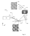
- FIGS. 8 and 9 A further example of an apparatus and method for obtaining data describing a three-dimensional product structure will now be described with reference to FIGS. 8 and 9 .
- This example uses an inspection apparatus substantially identical to that shown in FIG. 6 to perform the method.
- some parts of the optical system 800 are labeled with reference signs similar to those used in FIG. 6 , but with prefix “ 8 ” instead of “ 6 ”.
- prefix “ 8 ” instead of “ 6 ”.
- the inspection apparatus 800 comprises a radiation source 802 , such as an EUV radiation source.
- the radiation source is adapted to emit a only a single wavelength at any time, but to be tunable over a wavelength spectrum. This enables the wavelength of the radiation beam 830 to be varied over time so as to enable measurements to be carried out using different wavelengths.
- FIGS. 10 and 11 Another example of an inspection apparatus and method for obtaining data describing a three.dimensional product structure will now be described with reference to FIGS. 10 and 11 .
- some parts of the optical system 1000 are labeled with reference signs similar to those used in FIG. 6 , but with prefix “ 10 ” instead of “ 6 ”.
- prefix “ 10 ” instead of “ 6 ”.
- the inspection apparatus comprises an optical element, such as an optical filter, 1074 .
- the optical element may in one example be positioned directly in front of the detector 1008 (indicated in FIG. 10 by reference numeral 1074 a ). Alternatively, the optical element may be positioned between the output of the radiation source 1002 and the illumination optical system 1004 (as indicated by reference numeral 1074 b in FIG. 10 ).
- the optical element is configured to only let radiation with a specific wavelength pass and to block all other wavelengths (also referred to as a “band pass” filter).
- the pass wavelength of the optical element 1074 may be varied so as to allow the product structure to be illuminated with radiation having different wavelengths. In other terms, the optical element 1074 achieves the same effect as the tunable radiation source 802 in FIG.
- a fifth step 1105 the captured diffraction patterns 1070 are used to reconstruct data describing the three-dimensional product structure as described with reference to FIGS. 6 and 7 above.
- the inspection apparatus comprises a radiation source 1202 that emits radiation 1224 with a first wavelength spectrum, the wavelength spectrum comprising a plurality of wavelengths.
- the product structure 1298 is illuminated with the first and second time-delayed radiation pulses 1288 that have a first time delay t.
- the first time delay t is comprised in a plurality of time delays.
- Individual time delay values to be used can be determined in any suitable fashion. In one example, the user may predefine the time delay values. In another example, the time delay values may be defined based on prior measurement data or on statistical data. In yet another example, the time delay values may be a series of incrementally increasing time delays.
- first and second scattered radiation pulses 1260 which have been scattered by the product structure, are received at the detector 1208 . From the first and second scattered radiation pulses, a diffraction pattern is then reconstructed.
- a third step 1303 the time delay t between the first and the second radiation pulses is changed to another time delay value comprised in the plurality of time delays.
- an embodiment may include a computer program containing one or more sequences of machine-readable instructions defining methods of reconstructing diffracting patterns and/or data describing three-dimensional product structures, as well as controlling the inspection apparatus 400 to implement the illumination modes and other aspects of those metrology recipes.
- This computer program may be executed for example in a separate computer system employed for the image calculation/control process.
- the calculation steps may be wholly or partly performed within processing unit PU in the apparatus of FIG. 4, 6, 8, 10 or 12 and/or the control unit LACU of FIGS. 1 and 2 .
- a data storage medium e.g., semiconductor memory, magnetic or optical disk having such a computer program stored therein.
- step of capturing comprises using an optical element to progressively capture one diffraction pattern of the plurality of diffraction patterns at each of the wavelengths of the first plurality of wavelengths.
- An inspection apparatus according to clause 10 or 11, wherein the illuminating radiation comprises radiation with a first wavelength spectrum, the first wavelength spectrum comprising a plurality of wavelengths.
- a lithographic apparatus comprising an inspection apparatus according to any of clauses 9-17.
Landscapes
- Physics & Mathematics (AREA)
- General Physics & Mathematics (AREA)
- Chemical & Material Sciences (AREA)
- Optics & Photonics (AREA)
- Life Sciences & Earth Sciences (AREA)
- Crystallography & Structural Chemistry (AREA)
- Biochemistry (AREA)
- General Health & Medical Sciences (AREA)
- Health & Medical Sciences (AREA)
- Immunology (AREA)
- Pathology (AREA)
- Analytical Chemistry (AREA)
- Engineering & Computer Science (AREA)
- Plasma & Fusion (AREA)
- Electromagnetism (AREA)
- Exposure And Positioning Against Photoresist Photosensitive Materials (AREA)
- Investigating Materials By The Use Of Optical Means Adapted For Particular Applications (AREA)
- Length Measuring Devices By Optical Means (AREA)
Applications Claiming Priority (3)
| Application Number | Priority Date | Filing Date | Title |
|---|---|---|---|
| EP15201162.3 | 2015-12-18 | ||
| EP15201162 | 2015-12-18 | ||
| EP15201162 | 2015-12-18 |
Publications (2)
| Publication Number | Publication Date |
|---|---|
| US20170176879A1 US20170176879A1 (en) | 2017-06-22 |
| US10088762B2 true US10088762B2 (en) | 2018-10-02 |
Family
ID=54979468
Family Applications (1)
| Application Number | Title | Priority Date | Filing Date |
|---|---|---|---|
| US15/381,980 Active 2037-01-05 US10088762B2 (en) | 2015-12-18 | 2016-12-16 | Inspection apparatus and method |
Country Status (5)
| Country | Link |
|---|---|
| US (1) | US10088762B2 (he) |
| IL (1) | IL259578B (he) |
| NL (1) | NL2017928A (he) |
| TW (1) | TW201725355A (he) |
| WO (1) | WO2017102406A1 (he) |
Cited By (1)
| Publication number | Priority date | Publication date | Assignee | Title |
|---|---|---|---|---|
| WO2020150634A1 (en) * | 2019-01-17 | 2020-07-23 | KM Labs Inc. | Quantum-limited extended ultraviolet / x-ray coherent diffraction imaging |
Families Citing this family (13)
| Publication number | Priority date | Publication date | Assignee | Title |
|---|---|---|---|---|
| EP3435161A1 (en) * | 2017-07-24 | 2019-01-30 | ASML Netherlands B.V. | Determining an edge roughness parameter of a periodic structure |
| KR102428750B1 (ko) | 2017-10-19 | 2022-08-02 | 사이머 엘엘씨 | 단일의 리소그래피 노광 패스로 복수의 에어리얼 이미지를 형성하는 방법 |
| JP6440152B1 (ja) * | 2018-03-08 | 2018-12-19 | レーザーテック株式会社 | 検査装置及び検査方法 |
| JP7044894B2 (ja) | 2018-03-30 | 2022-03-30 | サイマー リミテッド ライアビリティ カンパニー | パルス光ビームのスペクトル特性選択及びパルスタイミング制御 |
| EP3561496B1 (en) * | 2018-04-24 | 2021-10-06 | Rigaku Corporation | Technique for processing x-ray diffraction data |
| TWI708041B (zh) * | 2018-10-17 | 2020-10-21 | 所羅門股份有限公司 | 檢測與標記瑕疵的方法 |
| CN113196176A (zh) * | 2018-12-21 | 2021-07-30 | Asml荷兰有限公司 | 用于计量的方法和装置 |
| EP3696606A1 (en) * | 2019-02-15 | 2020-08-19 | ASML Netherlands B.V. | A metrology apparatus with radiation source having multiple broadband outputs |
| WO2020180470A1 (en) * | 2019-03-01 | 2020-09-10 | Applied Materials, Inc. | Transparent wafer center finder |
| TWI814909B (zh) * | 2019-09-27 | 2023-09-11 | 聯華電子股份有限公司 | 多層對位標記及其對位方法 |
| CN113295106B (zh) * | 2021-05-26 | 2022-07-15 | 清华大学 | 一种双光梳散斑干涉测量系统及测量方法 |
| WO2023165783A1 (en) * | 2022-03-01 | 2023-09-07 | Asml Netherlands B.V. | Apparatus and methods for filtering measurement radiation |
| EP4250010A1 (en) * | 2022-03-25 | 2023-09-27 | ASML Netherlands B.V. | Apparatus and methods for filtering measurement radiation |
Citations (10)
| Publication number | Priority date | Publication date | Assignee | Title |
|---|---|---|---|---|
| JPH01319727A (ja) | 1988-06-22 | 1989-12-26 | Sony Corp | 光学装置 |
| US6623893B1 (en) | 2001-01-26 | 2003-09-23 | Advanced Micro Devices, Inc. | Pellicle for use in EUV lithography and a method of making such a pellicle |
| US20050286599A1 (en) | 2004-06-29 | 2005-12-29 | Rafac Robert J | Method and apparatus for gas discharge laser output light coherency reduction |
| US20060066855A1 (en) | 2004-08-16 | 2006-03-30 | Asml Netherlands B.V. | Method and apparatus for angular-resolved spectroscopic lithography characterization |
| US20080144671A1 (en) | 2005-11-01 | 2008-06-19 | Cymer, Inc. | Laser system |
| US20080212075A1 (en) | 2007-02-27 | 2008-09-04 | The Texas A&M University System | Short-wavelength coherence tomography |
| US7548575B1 (en) | 2006-05-24 | 2009-06-16 | Lockheed Martin Corporation | Self-seeding and phase-locking of an array of lasers |
| US20110102753A1 (en) | 2008-04-21 | 2011-05-05 | Asml Netherlands B.V. | Apparatus and Method of Measuring a Property of a Substrate |
| US20120044470A1 (en) | 2010-08-18 | 2012-02-23 | Asml Netherlands B.V. | Substrate for Use in Metrology, Metrology Method and Device Manufacturing Method |
| WO2017016903A1 (en) | 2015-07-30 | 2017-02-02 | Asml Netherlands B.V. | Inspection apparatus, inspection method and manufacturing method |
-
2016
- 2016-12-05 WO PCT/EP2016/079770 patent/WO2017102406A1/en active Application Filing
- 2016-12-05 NL NL2017928A patent/NL2017928A/en unknown
- 2016-12-16 TW TW105141921A patent/TW201725355A/zh unknown
- 2016-12-16 US US15/381,980 patent/US10088762B2/en active Active
-
2018
- 2018-05-24 IL IL259578A patent/IL259578B/he unknown
Patent Citations (11)
| Publication number | Priority date | Publication date | Assignee | Title |
|---|---|---|---|---|
| JPH01319727A (ja) | 1988-06-22 | 1989-12-26 | Sony Corp | 光学装置 |
| US6623893B1 (en) | 2001-01-26 | 2003-09-23 | Advanced Micro Devices, Inc. | Pellicle for use in EUV lithography and a method of making such a pellicle |
| US20050286599A1 (en) | 2004-06-29 | 2005-12-29 | Rafac Robert J | Method and apparatus for gas discharge laser output light coherency reduction |
| US20060066855A1 (en) | 2004-08-16 | 2006-03-30 | Asml Netherlands B.V. | Method and apparatus for angular-resolved spectroscopic lithography characterization |
| US7791732B2 (en) * | 2004-08-16 | 2010-09-07 | Asml Netherlands B.V. | Method and apparatus for angular-resolved spectroscopic lithography characterization |
| US20080144671A1 (en) | 2005-11-01 | 2008-06-19 | Cymer, Inc. | Laser system |
| US7548575B1 (en) | 2006-05-24 | 2009-06-16 | Lockheed Martin Corporation | Self-seeding and phase-locking of an array of lasers |
| US20080212075A1 (en) | 2007-02-27 | 2008-09-04 | The Texas A&M University System | Short-wavelength coherence tomography |
| US20110102753A1 (en) | 2008-04-21 | 2011-05-05 | Asml Netherlands B.V. | Apparatus and Method of Measuring a Property of a Substrate |
| US20120044470A1 (en) | 2010-08-18 | 2012-02-23 | Asml Netherlands B.V. | Substrate for Use in Metrology, Metrology Method and Device Manufacturing Method |
| WO2017016903A1 (en) | 2015-07-30 | 2017-02-02 | Asml Netherlands B.V. | Inspection apparatus, inspection method and manufacturing method |
Non-Patent Citations (11)
| Title |
|---|
| Bao et al., "Lensless phase microscopy using phase retrieval with multiple illumination wavelengths," Optical Society of America, Applied Optics, vol. 51, No. 22, Aug. 1, 2012; pp. 5486-5494. |
| Bao et al., "Phase retrieval using multiple illumination wavelengths," Optical Society of America, Optics Letters, vol. 33, No. 4, Feb. 15, 2008; pp. 309-311. |
| Claus et al., "Dual wavelength optical metrology using ptychography," Journal of Optics, vol. 15, No. 3, 2013; pp. 1-7. |
| English-language abstract for Japanese Patent Publication No. H1-319727, published Dec. 26, 1989; 2 pages. |
| Huang et al., "Optical Coherence Tomography," Science, New Series, vol. 254, No. 5035, Nov. 22, 1991; pp. 1178-1181. |
| International Search Report and Written Opinion of the International Searching Authority directed to related International Patent Application No. PCT/EP2016/079770, dated Apr. 25, 2017; 14 pages. |
| Kuhn et al., "Submicrometer tomography of cells by multiple-wavelength digital holographic microscopy in reflection," Optic Letters, vol. 34, No. 5, Mar. 1, 2009; pp. 653-655. |
| Lee et al., "A novel concept for actinic EUV mask review tool using a scanning lensless imaging method at the Swiss Light Source," Extreme Ultraviolet (EUV) Lithography V, SPIE, vol. 9048, No. 904811, 2014; pp. 1-7. |
| Seaberg et al., "Ultrahigh 22 nm resolution coherent diffractive imaging using a desktop 13 nm high harmonic source," Optical Society of America, Optics Express, vol. 19, No. 23, Nov. 7, 2011; pp. 22470-22479. |
| Witte et al., "Lensless diffractive imaging with ultra-broadband table-top sources: from infrared to extreme-ultraviolet wavelengths," Light: Science & Applications 3, e163, 2014; pp. 1-8. |
| Zhang, B., "EUV Microscopy with a Tabletop High Harmonic Generation Source: Generalizing Coherent Diffractive Imaging to Extended Samples in Transmission, Reflection, and Hyperspectral Modalities," University of Science and Technology of China, Department of Physics, 2007; 119 pages. |
Cited By (3)
| Publication number | Priority date | Publication date | Assignee | Title |
|---|---|---|---|---|
| WO2020150634A1 (en) * | 2019-01-17 | 2020-07-23 | KM Labs Inc. | Quantum-limited extended ultraviolet / x-ray coherent diffraction imaging |
| US20220100094A1 (en) * | 2019-01-17 | 2022-03-31 | Kapteyn Murnane Laboratories, Inc. Dba Km Labs Inc. | Quantum-limited Extreme Ultraviolet Coherent Diffraction Imaging |
| US12085520B2 (en) * | 2019-01-17 | 2024-09-10 | Regents Of The Univ Of Colorado | Quantum-limited extreme ultraviolet coherent diffraction imaging |
Also Published As
| Publication number | Publication date |
|---|---|
| IL259578A (he) | 2018-07-31 |
| WO2017102406A1 (en) | 2017-06-22 |
| TW201725355A (zh) | 2017-07-16 |
| NL2017928A (en) | 2017-06-28 |
| US20170176879A1 (en) | 2017-06-22 |
| IL259578B (he) | 2022-04-01 |
Similar Documents
| Publication | Publication Date | Title |
|---|---|---|
| US10088762B2 (en) | Inspection apparatus and method | |
| US9823586B2 (en) | Inspection apparatus, inspection method and manufacturing method | |
| KR102190305B1 (ko) | 메트롤로지 방법, 메트롤로지 장치 및 디바이스 제조 방법 | |
| US10816906B2 (en) | HHG source, inspection apparatus and method for performing a measurement | |
| US20170031246A1 (en) | Inspection Apparatus, Inspection Method and Manufacturing Method | |
| US10649344B2 (en) | Illumination source for an inspection apparatus, inspection apparatus and inspection method | |
| EP3296723A1 (en) | Illumination source for an inspection apparatus, inspection apparatus and inspection method | |
| TW201730546A (zh) | 微影裝置及用於執行量測之方法 | |
| CN110832401B (zh) | 确定周期性结构的边缘粗糙度参数 | |
| US10459347B2 (en) | Inspection method, inspection apparatus and illumination method and apparatus | |
| TWI631321B (zh) | 用於檢測裝置之照明源、檢測裝置及檢測方法 | |
| US20190235394A1 (en) | Method of patterning at least a layer of a semiconductor device |
Legal Events
| Date | Code | Title | Description |
|---|---|---|---|
| AS | Assignment |
Owner name: ASML NETHERLANDS B.V., NETHERLANDS Free format text: ASSIGNMENT OF ASSIGNORS INTEREST;ASSIGNOR:UNIVERSITEIT VAN AMSTERDAM;REEL/FRAME:045352/0178 Effective date: 20170803 |
|
| AS | Assignment |
Owner name: ASML NETHERLANDS B.V., NETHERLANDS Free format text: ASSIGNMENT OF ASSIGNORS INTEREST;ASSIGNORS:STICHTING VU;WITTE, STEFAN MICHIEL;EIKEMA, KJELD SIJBRAND EDUARD;SIGNING DATES FROM 20171129 TO 20171205;REEL/FRAME:045369/0069 Owner name: STICHTING NEDERLANDSE WETENSCHAPPELIJK ONDERZOEK I Free format text: CHANGE OF NAME;ASSIGNOR:STICHTING VOOR FUNDAMENTEEL ONDERZOEK DER MATERIE;REEL/FRAME:045377/0032 Effective date: 20170529 Owner name: ASML NETHERLANDS B.V., NETHERLANDS Free format text: ASSIGNMENT OF ASSIGNORS INTEREST;ASSIGNOR:STICHTING NEDERLANDSE WETENSCHAPPELIJK ONDERZOEK INSTITUTEN;REEL/FRAME:045377/0068 Effective date: 20171130 |
|
| STCF | Information on status: patent grant |
Free format text: PATENTED CASE |
|
| MAFP | Maintenance fee payment |
Free format text: PAYMENT OF MAINTENANCE FEE, 4TH YEAR, LARGE ENTITY (ORIGINAL EVENT CODE: M1551); ENTITY STATUS OF PATENT OWNER: LARGE ENTITY Year of fee payment: 4 |