US10024678B2 - Wearable clip for providing social and environmental awareness - Google Patents
Wearable clip for providing social and environmental awareness Download PDFInfo
- Publication number
- US10024678B2 US10024678B2 US14/489,420 US201414489420A US10024678B2 US 10024678 B2 US10024678 B2 US 10024678B2 US 201414489420 A US201414489420 A US 201414489420A US 10024678 B2 US10024678 B2 US 10024678B2
- Authority
- US
- United States
- Prior art keywords
- clip
- user
- data
- processor
- camera
- Prior art date
- Legal status (The legal status is an assumption and is not a legal conclusion. Google has not performed a legal analysis and makes no representation as to the accuracy of the status listed.)
- Active
Links
Images


Classifications
-
- G—PHYSICS
- G01—MEASURING; TESTING
- G01C—MEASURING DISTANCES, LEVELS OR BEARINGS; SURVEYING; NAVIGATION; GYROSCOPIC INSTRUMENTS; PHOTOGRAMMETRY OR VIDEOGRAMMETRY
- G01C21/00—Navigation; Navigational instruments not provided for in groups G01C1/00 - G01C19/00
- G01C21/26—Navigation; Navigational instruments not provided for in groups G01C1/00 - G01C19/00 specially adapted for navigation in a road network
- G01C21/34—Route searching; Route guidance
- G01C21/36—Input/output arrangements for on-board computers
- G01C21/3605—Destination input or retrieval
- G01C21/3617—Destination input or retrieval using user history, behaviour, conditions or preferences, e.g. predicted or inferred from previous use or current movement
-
- G—PHYSICS
- G01—MEASURING; TESTING
- G01C—MEASURING DISTANCES, LEVELS OR BEARINGS; SURVEYING; NAVIGATION; GYROSCOPIC INSTRUMENTS; PHOTOGRAMMETRY OR VIDEOGRAMMETRY
- G01C21/00—Navigation; Navigational instruments not provided for in groups G01C1/00 - G01C19/00
- G01C21/10—Navigation; Navigational instruments not provided for in groups G01C1/00 - G01C19/00 by using measurements of speed or acceleration
- G01C21/12—Navigation; Navigational instruments not provided for in groups G01C1/00 - G01C19/00 by using measurements of speed or acceleration executed aboard the object being navigated; Dead reckoning
- G01C21/16—Navigation; Navigational instruments not provided for in groups G01C1/00 - G01C19/00 by using measurements of speed or acceleration executed aboard the object being navigated; Dead reckoning by integrating acceleration or speed, i.e. inertial navigation
- G01C21/165—Navigation; Navigational instruments not provided for in groups G01C1/00 - G01C19/00 by using measurements of speed or acceleration executed aboard the object being navigated; Dead reckoning by integrating acceleration or speed, i.e. inertial navigation combined with non-inertial navigation instruments
- G01C21/1656—Navigation; Navigational instruments not provided for in groups G01C1/00 - G01C19/00 by using measurements of speed or acceleration executed aboard the object being navigated; Dead reckoning by integrating acceleration or speed, i.e. inertial navigation combined with non-inertial navigation instruments with passive imaging devices, e.g. cameras
-
- G—PHYSICS
- G01—MEASURING; TESTING
- G01S—RADIO DIRECTION-FINDING; RADIO NAVIGATION; DETERMINING DISTANCE OR VELOCITY BY USE OF RADIO WAVES; LOCATING OR PRESENCE-DETECTING BY USE OF THE REFLECTION OR RERADIATION OF RADIO WAVES; ANALOGOUS ARRANGEMENTS USING OTHER WAVES
- G01S19/00—Satellite radio beacon positioning systems; Determining position, velocity or attitude using signals transmitted by such systems
- G01S19/01—Satellite radio beacon positioning systems transmitting time-stamped messages, e.g. GPS [Global Positioning System], GLONASS [Global Orbiting Navigation Satellite System] or GALILEO
- G01S19/13—Receivers
- G01S19/14—Receivers specially adapted for specific applications
-
- G—PHYSICS
- G01—MEASURING; TESTING
- G01S—RADIO DIRECTION-FINDING; RADIO NAVIGATION; DETERMINING DISTANCE OR VELOCITY BY USE OF RADIO WAVES; LOCATING OR PRESENCE-DETECTING BY USE OF THE REFLECTION OR RERADIATION OF RADIO WAVES; ANALOGOUS ARRANGEMENTS USING OTHER WAVES
- G01S19/00—Satellite radio beacon positioning systems; Determining position, velocity or attitude using signals transmitted by such systems
- G01S19/38—Determining a navigation solution using signals transmitted by a satellite radio beacon positioning system
- G01S19/39—Determining a navigation solution using signals transmitted by a satellite radio beacon positioning system the satellite radio beacon positioning system transmitting time-stamped messages, e.g. GPS [Global Positioning System], GLONASS [Global Orbiting Navigation Satellite System] or GALILEO
- G01S19/42—Determining position
- G01S19/48—Determining position by combining or switching between position solutions derived from the satellite radio beacon positioning system and position solutions derived from a further system
- G01S19/485—Determining position by combining or switching between position solutions derived from the satellite radio beacon positioning system and position solutions derived from a further system whereby the further system is an optical system or imaging system
-
- G—PHYSICS
- G01—MEASURING; TESTING
- G01S—RADIO DIRECTION-FINDING; RADIO NAVIGATION; DETERMINING DISTANCE OR VELOCITY BY USE OF RADIO WAVES; LOCATING OR PRESENCE-DETECTING BY USE OF THE REFLECTION OR RERADIATION OF RADIO WAVES; ANALOGOUS ARRANGEMENTS USING OTHER WAVES
- G01S19/00—Satellite radio beacon positioning systems; Determining position, velocity or attitude using signals transmitted by such systems
- G01S19/38—Determining a navigation solution using signals transmitted by a satellite radio beacon positioning system
- G01S19/39—Determining a navigation solution using signals transmitted by a satellite radio beacon positioning system the satellite radio beacon positioning system transmitting time-stamped messages, e.g. GPS [Global Positioning System], GLONASS [Global Orbiting Navigation Satellite System] or GALILEO
- G01S19/42—Determining position
- G01S19/48—Determining position by combining or switching between position solutions derived from the satellite radio beacon positioning system and position solutions derived from a further system
- G01S19/49—Determining position by combining or switching between position solutions derived from the satellite radio beacon positioning system and position solutions derived from a further system whereby the further system is an inertial position system, e.g. loosely-coupled
-
- G06K9/00476—
-
- G06K9/00664—
-
- G06K9/46—
-
- G—PHYSICS
- G06—COMPUTING; CALCULATING OR COUNTING
- G06V—IMAGE OR VIDEO RECOGNITION OR UNDERSTANDING
- G06V20/00—Scenes; Scene-specific elements
- G06V20/10—Terrestrial scenes
-
- G—PHYSICS
- G08—SIGNALLING
- G08B—SIGNALLING OR CALLING SYSTEMS; ORDER TELEGRAPHS; ALARM SYSTEMS
- G08B13/00—Burglar, theft or intruder alarms
- G08B13/22—Electrical actuation
- G08B13/24—Electrical actuation by interference with electromagnetic field distribution
- G08B13/2402—Electronic Article Surveillance [EAS], i.e. systems using tags for detecting removal of a tagged item from a secure area, e.g. tags for detecting shoplifting
- G08B13/2451—Specific applications combined with EAS
- G08B13/2462—Asset location systems combined with EAS
-
- G—PHYSICS
- G08—SIGNALLING
- G08B—SIGNALLING OR CALLING SYSTEMS; ORDER TELEGRAPHS; ALARM SYSTEMS
- G08B25/00—Alarm systems in which the location of the alarm condition is signalled to a central station, e.g. fire or police telegraphic systems
- G08B25/01—Alarm systems in which the location of the alarm condition is signalled to a central station, e.g. fire or police telegraphic systems characterised by the transmission medium
- G08B25/08—Alarm systems in which the location of the alarm condition is signalled to a central station, e.g. fire or police telegraphic systems characterised by the transmission medium using communication transmission lines
-
- G—PHYSICS
- G08—SIGNALLING
- G08B—SIGNALLING OR CALLING SYSTEMS; ORDER TELEGRAPHS; ALARM SYSTEMS
- G08B6/00—Tactile signalling systems, e.g. personal calling systems
-
- H—ELECTRICITY
- H04—ELECTRIC COMMUNICATION TECHNIQUE
- H04N—PICTORIAL COMMUNICATION, e.g. TELEVISION
- H04N7/00—Television systems
- H04N7/18—Closed-circuit television [CCTV] systems, i.e. systems in which the video signal is not broadcast
-
- H—ELECTRICITY
- H04—ELECTRIC COMMUNICATION TECHNIQUE
- H04W—WIRELESS COMMUNICATION NETWORKS
- H04W4/00—Services specially adapted for wireless communication networks; Facilities therefor
- H04W4/02—Services making use of location information
-
- H—ELECTRICITY
- H04—ELECTRIC COMMUNICATION TECHNIQUE
- H04W—WIRELESS COMMUNICATION NETWORKS
- H04W4/00—Services specially adapted for wireless communication networks; Facilities therefor
- H04W4/02—Services making use of location information
- H04W4/024—Guidance services
-
- G—PHYSICS
- G01—MEASURING; TESTING
- G01C—MEASURING DISTANCES, LEVELS OR BEARINGS; SURVEYING; NAVIGATION; GYROSCOPIC INSTRUMENTS; PHOTOGRAMMETRY OR VIDEOGRAMMETRY
- G01C21/00—Navigation; Navigational instruments not provided for in groups G01C1/00 - G01C19/00
- G01C21/10—Navigation; Navigational instruments not provided for in groups G01C1/00 - G01C19/00 by using measurements of speed or acceleration
- G01C21/12—Navigation; Navigational instruments not provided for in groups G01C1/00 - G01C19/00 by using measurements of speed or acceleration executed aboard the object being navigated; Dead reckoning
- G01C21/16—Navigation; Navigational instruments not provided for in groups G01C1/00 - G01C19/00 by using measurements of speed or acceleration executed aboard the object being navigated; Dead reckoning by integrating acceleration or speed, i.e. inertial navigation
- G01C21/165—Navigation; Navigational instruments not provided for in groups G01C1/00 - G01C19/00 by using measurements of speed or acceleration executed aboard the object being navigated; Dead reckoning by integrating acceleration or speed, i.e. inertial navigation combined with non-inertial navigation instruments
-
- G—PHYSICS
- G01—MEASURING; TESTING
- G01C—MEASURING DISTANCES, LEVELS OR BEARINGS; SURVEYING; NAVIGATION; GYROSCOPIC INSTRUMENTS; PHOTOGRAMMETRY OR VIDEOGRAMMETRY
- G01C21/00—Navigation; Navigational instruments not provided for in groups G01C1/00 - G01C19/00
- G01C21/20—Instruments for performing navigational calculations
- G01C21/206—Instruments for performing navigational calculations specially adapted for indoor navigation
-
- G—PHYSICS
- G01—MEASURING; TESTING
- G01C—MEASURING DISTANCES, LEVELS OR BEARINGS; SURVEYING; NAVIGATION; GYROSCOPIC INSTRUMENTS; PHOTOGRAMMETRY OR VIDEOGRAMMETRY
- G01C21/00—Navigation; Navigational instruments not provided for in groups G01C1/00 - G01C19/00
- G01C21/26—Navigation; Navigational instruments not provided for in groups G01C1/00 - G01C19/00 specially adapted for navigation in a road network
- G01C21/34—Route searching; Route guidance
- G01C21/36—Input/output arrangements for on-board computers
- G01C21/3626—Details of the output of route guidance instructions
- G01C21/3629—Guidance using speech or audio output, e.g. text-to-speech
-
- G—PHYSICS
- G01—MEASURING; TESTING
- G01C—MEASURING DISTANCES, LEVELS OR BEARINGS; SURVEYING; NAVIGATION; GYROSCOPIC INSTRUMENTS; PHOTOGRAMMETRY OR VIDEOGRAMMETRY
- G01C21/00—Navigation; Navigational instruments not provided for in groups G01C1/00 - G01C19/00
- G01C21/26—Navigation; Navigational instruments not provided for in groups G01C1/00 - G01C19/00 specially adapted for navigation in a road network
- G01C21/34—Route searching; Route guidance
- G01C21/36—Input/output arrangements for on-board computers
- G01C21/3626—Details of the output of route guidance instructions
- G01C21/3652—Guidance using non-audiovisual output, e.g. tactile, haptic or electric stimuli
-
- G06K2209/27—
-
- G—PHYSICS
- G06—COMPUTING; CALCULATING OR COUNTING
- G06V—IMAGE OR VIDEO RECOGNITION OR UNDERSTANDING
- G06V2201/00—Indexing scheme relating to image or video recognition or understanding
- G06V2201/10—Recognition assisted with metadata
-
- G—PHYSICS
- G08—SIGNALLING
- G08B—SIGNALLING OR CALLING SYSTEMS; ORDER TELEGRAPHS; ALARM SYSTEMS
- G08B3/00—Audible signalling systems; Audible personal calling systems
- G08B3/10—Audible signalling systems; Audible personal calling systems using electric transmission; using electromagnetic transmission
Definitions
- the present disclosure relates to a wearable device. More specifically, the present disclosure relates to a clip which provides haptic and audio feedback based on various sensors and user input.
- Wearable devices currently exist in the art which have an input, such as a camera, an output, such as a speaker, and a processor.
- these devices are not optimized to assist users having certain physical disabilities. For example, they do not proactively collect data regarding the user and the environment of the user to achieve an understanding of the user and the user's environment. These devices also do not proactively provide helpful information or assistance to the user. In other words, the devices known in the art do not proactively aid the user in navigation, environmental awareness, and social interactions.
- the intelligent clip includes an inertial measurement unit (IMU) sensor coupled to the intelligent clip.
- the IMU is configured to detect inertial measurement data corresponding to a positioning, velocity, or acceleration of the intelligent clip.
- the intelligent clip also includes a global positioning system (GPS) unit coupled to the intelligent clip.
- GPS global positioning system
- the GPS unit is configured to detect location data corresponding to a location of the intelligent clip.
- the intelligent clip also includes at least one camera coupled to the intelligent clip. The at least one camera is configured to detect image data corresponding to a surrounding environment of the intelligent clip.
- the intelligent clip also includes a memory configured to store object data regarding previously determined objects and previously determined user data associated with the user.
- the intelligent clip also includes a first processor connected to the IMU, the GPS unit and the at least one camera.
- the first processor is adapted to recognize an object in the surrounding environment by analyzing the image data based on the stored object data and at least one of the inertial measurement data or the location data.
- the first processor is also adapted to determine a desirable event or action based on the recognized object, the previously determined user data, and a current time or day.
- the first processor is also adapted to determine a destination based on the determined desirable event or action.
- the first processor is also adapted to determine a navigation path for navigating the intelligent clip to the destination based on the determined destination, the image data, and at least one of the inertial measurement data or the location data.
- the first processor is also adapted to determine output data based on the determined navigation path.
- the intelligent clip also includes a speaker that is configured to provide audio information to the user based on at least one of the recognized object, determined desirable event or action, or navigation path.
- the method includes detecting, via a camera, a GPS unit or an IMU, inertial measurement data corresponding to a positioning, velocity, or acceleration of the intelligent clip. Also detected may be location data corresponding to a location of the intelligent clip or image data corresponding to a surrounding environment of the intelligent clip.
- the method also includes storing, in a memory, object data regarding previously determined objects and previously determined user data regarding a user.
- the method also includes recognizing, by a processor, an object in the surrounding environment. The object is recognized by analyzing the image data based on the stored object data and at least one of the inertial measurement data or the location data.
- the method also includes determining, by the processor, a desirable event or action based on the recognized object, the previously determined user data, and a current time or day.
- the processor may also determine a destination based on the determined desirable event or action.
- the processor may also determine a navigation path for navigating the intelligent clip to the destination based on the determined destination, the image data, and at least one of the inertial measurement data or the location data.
- the processor may also determine output data based on the determined navigation path.
- the method also includes providing, via a speaker or a vibration unit, audio or haptic information to the user. The information is provided based on at least one of the recognized object, the determined desirable event or action, or the navigation path.
- the intelligent clip to be worn by a user.
- the intelligent clip includes a front, a back, a first side and a second side.
- the intelligent clip also includes an inertial measurement unit (IMU) sensor coupled to the intelligent clip.
- the IMU sensor is configured to detect inertial measurement data corresponding to a positioning, velocity, or acceleration of the intelligent clip.
- the intelligent clip also includes a global positioning system (GPS) unit coupled to the intelligent clip.
- GPS unit is configured to detect location data corresponding to a location of the intelligent clip.
- the intelligent clip also includes a first camera positioned on the front of the intelligent clip and coupled to the intelligent clip. The first camera is configured to detect a first image data corresponding to a surrounding environment of the intelligent clip.
- the intelligent clip also includes a second camera positioned on either the first side of the intelligent clip or the second side of the intelligent clip and coupled to the intelligent clip.
- the second camera is configured to detect a second image data corresponding to the surrounding environment of the intelligent clip.
- the intelligent clip also includes a memory that is configured to store object data regarding previously determined objects. The memory may also store previously determined user data associated with the user.
- the intelligent clip also includes a processor connected to the IMU, the GPS unit, the first camera and the second camera. The processor is configured to recognize an object in the surrounding environment by analyzing the first image data and the second image data. The object is analyzed based on the stored object data and at least one of the inertial measurement data or the location data.
- the processor is also configured to determine a desirable event or action based on the recognized object, the previously determined user data, and a current time or day.
- the processor is also configured to determine a destination based on the determined desirable event or action.
- the processor is also configured to determine a navigation path for navigating the intelligent clip to the destination. The navigation path is based on the determined destination, the first image data, the second image data, and at least one of the inertial measurement data or the location data.
- the processor is also configured to determine output data based on the determined navigation path.
- the intelligent clip also includes a speaker configured to provide audio information to the user based on at least one of the recognized object, determined desirable event or action, or navigation path.
- FIG. 1A is a block diagram of a clip according to an embodiment of the present invention.
- FIG. 1B illustrates a clip including a stereo camera pair, a button, a speaker and a USB port according to an embodiment of the present invention
- FIG. 1C illustrates the clip of FIG. 1B from a first side according to an embodiment of the present invention
- FIG. 1D illustrates the clip of FIG. 1B from a second side according to an embodiment of the present invention
- FIG. 1E illustrates the clip of FIG. 1B from the back according to an embodiment of the present invention
- FIG. 1F illustrates the clip of FIG. 1B from the top according to an embodiment of the present invention
- FIG. 1G illustrates a clasp for attaching a clip to a person according to an embodiment of the present invention
- FIG. 1H illustrates a lanyard for attaching a clip to a person according to an embodiment of the present invention
- FIG. 1I illustrates a clip including some of the internal components according to an embodiment of the present invention
- FIG. 1J illustrates a clip having two buttons, two cameras and a sensor according to an embodiment of the present invention
- FIG. 1K illustrates two clips attached together by a physical connector and an electrical connector according to an embodiment of the present invention
- FIG. 1L illustrates a clip wirelessly connected to a wireless smart device and a cloud according to an embodiment of the present invention
- FIG. 2 is a flowchart of an object recognition logic according to an embodiment of the present invention.
- FIG. 3A illustrates an object recognition logic applied to a visual data set according to an embodiment of the present invention
- FIG. 3B further illustrates the object recognition logic shown in FIG. 3A ;
- FIG. 3C further illustrates the object recognition logic shown in FIG. 3A ;
- FIG. 4 is a flowchart illustrating a method of estimating a position or orientation based on slice descriptors according to an implementation of the present disclosure
- FIG. 5 is a flowchart for outputting first and/or second output data for providing assistance to a user of a clip according to an embodiment of the present invention
- FIG. 6A illustrates an exemplary method for providing helpful information to a user of a clip based on detected data according to an embodiment of the present invention
- FIG. 6B illustrates an exemplary method for providing assistance to a user of a clip based on a determined desirable event, action, and/or destination, according to an embodiment of the present invention
- FIG. 7 illustrates an exemplary method for danger assistance by a clip according to an embodiment of the present invention
- FIG. 8A illustrates an exemplary method for safety monitoring and alerting using a clip according to an embodiment of the present invention
- FIG. 8B illustrates an example of the method of FIG. 8A according to an embodiment of the present invention
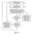
- FIG. 9A illustrates an exemplary method for providing navigation assistance to a user of a clip according to an embodiment of the present invention
- FIG. 9B illustrates an exemplary use of the method of FIG. 9A according to an embodiment of the present invention
- FIG. 10A illustrates an exemplary method for determining the location of a desired object by a clip according to an embodiment of the present invention
- FIG. 10B illustrates an exemplary use of the method of FIG. 10A according to an embodiment of the present invention.
- FIG. 11 illustrates an exemplary method for handling an obstruction of a camera on a clip according to an embodiment of the present invention.
- a connection may be a wired connection, a wireless connection, or a mix of wired and wireless connections.
- a connection also provides for communications propagating both ways along the connection.
- a connection with a processor provides for the processor to receive communications and to transmit communications over the connection.
- the wearable intelligent clip for providing social and environmental awareness provides several advantages over the current state of the art.
- the selection and placement of inputs on the wearable clip has been optimized. This provides the advantage of more accurate output being provided to the user. Also, the selection and placement of outputs has been optimized in order to provide information to the user in a more integrated and easier to understand fashion.
- the clip can continuously observe the user and his surroundings as well as store preference information, such as calendars and schedules, and access remote databases. Based on this observed data, the clip can proactively provide feedback to the user. Proactive functions can, for example, remind a user where he should be, inform the user of the name of a person he is speaking with, warn the user when the user may be approaching a hazardous situation, etc. This is advantageous over the state of the art because the user of the clip can be provided information without having to request it. This can result in the user being provided feedback that he may not have known he could receive. Additionally, it allows the user to receive feedback without wasting extra time or effort. In some circumstances, this proactive feedback can prevent potential embarrassment for the user (for example, he need not ask the clip the name of a person he is speaking with).
- the on board stereo camera of the clip (when included) provides useful depth and distance information to the device.
- the combination of a camera on the front of the clip as well as a camera on the side of the clip provides a larger total field of view for the clip. The clip can then use this information to better determine social and environmental elements around the user.
- the combination of the global positioning system (GPS), the inertial measurement unit (IMU) and the camera is advantageous as the combination can provide more accurate feedback to the user.
- FIG. 1A is a block diagram of an intelligent clip (clip) 100 according to an embodiment of the present invention.
- the clip 100 includes an onboard processing array 110 , which communicates with a sensor array 120 , an interface array 130 and a component array 140 .
- the arrays 110 , 120 , 130 and 140 are exemplary groupings to visually organize the components of the clip 100 in the block diagram of FIG. 1A and are not limiting or necessarily representative of any physical groupings. In addition, certain embodiments may have more or less components illustrated in FIG. 1A .
- the embodiments shown in FIGS. 1B-1K are examples physical designs of the clip 100 . The components can be arranged differently based on design concerns. Not all features and components described herein are shown in FIGS. 1B-1K . Furthermore, the structure in FIGS. 1B-1K may be modified or other embodiments of the clip 100 can be designed to include additional features described herein.
- the shape of the clip 100 can be designed based on comfort to the user, weight of the clip 100 , ability for the clip 100 to remain attached to the user and for placement of components. Some examples are illustrated in FIGS. 1B-1K .
- the design may also be optimized by utilizing light-weight and small components. Light-weight components allow the clip 100 to remain light and comfortable for the user. Small components allow the clip 100 to remain small, so that they do not feel bulky to the user. Connectivity to another device to perform certain functions is beneficial as it allows the clip 100 to remain light (as less bulky hardware is required on board) while still providing higher power computations.
- the onboard processing array 110 includes a processor 111 and a memory 112 .
- the processor 111 may be a computer processor such as an ARM processor, DSP processor, distributed processor, or other form of central processing.
- the memory 112 may be a RAM or other volatile or nonvolatile memory used by the processor 111 .
- the memory 112 may be a non-transitory memory or a data storage device, such as a hard disk drive, a solid state disk drive, a hybrid disk drive, or other appropriate data storage, and may further store machine-readable instructions, which may be loaded and executed by the processor 111 .
- the sensor array 120 includes a camera unit (camera) 121 , an inertial measurement unit (IMU) 123 , a global positioning system (GPS) 124 , and a sensor 125 .
- the camera 121 may include a pair of stereo cameras 121 A having at least two cameras offset by a stereo distance and/or a non-stereo camera 121 .
- the stereo distance may be optimized for the two cameras.
- camera 121 may refer to any pair of stereo cameras 121 A and/or any non-stereo camera 121 .
- Stereo cameras provide depth information in both indoor and outdoor environments.
- the pair of stereo cameras 121 A may face forward, in front of a user, to establish a field of view (FOV).
- the pair of stereo cameras 121 A may have, for example, an FOV of around 90 degrees.
- the pair of stereo cameras 121 A provides 3D information such as depth in front of the user.
- Additional cameras, such as a wide angle lens camera, which may be placed to the sides of the pair of stereo cameras 121 A or used in place of the pair of stereo cameras 121 A, may increase the FOV to, for example, around 120 degrees.
- the cameras 121 may be monocular, they can provide simple recognition, even without depth or distance information.
- the cameras 121 can detect moving objects in the user's periphery.
- the stereo cameras 121 A and/or the cameras 121 continuously recognize objects in the environment.
- the clip 100 provides the user with guidance and navigation commands by way of audio and haptic feedback.
- the clip 100 may include a wide-lens camera to increase the field of view.
- additional cameras may be monocular, they can provide simple recognition, even without depth or distance information.
- the cameras can detect moving objects in the user's periphery.
- the stereo cameras 121 A and the additional cameras continuously recognize objects in the environment.
- the clip 100 provides the user with guidance and navigation commands by way of audio and haptic feedback.
- the camera 121 may include a plurality of cameras. Adding multiple cameras might be beneficial as it may capture a view that may be obstructed by the device itself if a single camera is utilized. For example, a single camera's view may be blocked by a physical component of the clip 100 . To obtain a greater field of view, cameras may be positioned at different vantage points. The multiple images can be fit together via image processing to capture a broader spectrum of the surrounding environment.
- a wide lens camera 121 may be positioned on the front of the clip 100 to detect data in a forward direction and another camera 121 may be placed on a side of the clip 100 to detect data is a sideways direction.
- a third camera 121 may be positioned on the other side of the clip 100 to detect data in the other sideways direction.
- These cameras 121 may capture additional image data to be used at a later time, such as by filling in data correlating to a physical layout of an area, viewing a map to one side of the user, etc. This data may also be useful for real-time applications, such as identification of a friend (if a friend is standing to the right or the left of the user), danger avoidance (if a car is moving towards the user from the right or the left), etc.
- the clip 100 may assist the user in environmental awareness, navigation, social interactions, and obstacle avoidance through real-time feedback.
- the clip 100 is capable of recognizing objects around the user, in order to alert the user.
- the clip 100 may be used by a blind person to aid in environmental awareness and navigate safely around obstacles, to read text to a user and/or for object recognition and alerting.
- the clip 100 provides the user audio and haptic feedback through the speaker 132 and the vibration unit 133 , based upon camera input from the sensor array 120 (and input from the interface array 130 , such as audio input from a microphone 131 and/or user input from the input device 134 ).
- the clip 100 is designed to accommodate blind or partially blind users.
- a low-light viewing or night-vision camera e.g., infrared camera
- a camera may be directed to normal lighting and another directed to night vision.
- a blind user may be more likely to turn off the lights because he/she does not depend on the lighting.
- the clip 100 would still function properly by processing images of the night-vision camera.
- the image processed may be limited in night-vision. For example, facial recognition may not be feasible, but the presence of another person can be detected. As a result, helpful information can be given to the user.
- the clip 100 may include an infrared camera in combination with another camera or cameras 121 .
- an infrared camera in combination with another camera or cameras 121 .
- a wide angle camera 121 and/or a stereo camera 121 A may be utilized for image detection for normal lighting situations and an infrared camera may be utilized for image detection for darker situations.
- the visible light spectrum allows humans to detect certain details that other light spectrums may not provide. However, other light spectrums may provide certain details that human visible light spectrum cannot provide. Details of certain objects may not be easily detected by the visible light spectrum during a cloudy or foggy day. Another spectrum of light may provide better details of objects during certain conditions. These spectrums may include extreme ultraviolet, near infrared, mid infrared, far infrared, etc.
- different cameras 121 may be provided for detecting various light spectrum data. In some embodiments, a single camera 121 is provided that detects a spectrum of light other than the visible light spectrum.
- the clip 100 may be applied to other uses of daily life. For example, it can be used to record life events (i.e. weddings, sporting events, etc.). It may also be utilized to aid peace officers, such as by recording arrests, traffic stops, etc. It may also be used by workers, for example, by visually identifying hazardous items in the environment and alerting the worker.
- life events i.e. weddings, sporting events, etc.
- peace officers such as by recording arrests, traffic stops, etc.
- workers for example, by visually identifying hazardous items in the environment and alerting the worker.
- the IMU 123 may comprise one or more of an accelerometer, a gyroscope, and/or a magnetometer.
- the GPS 124 may be one or more GPS units.
- the IMU 123 and/or the GPS 124 may be utilized to determine the location and/or positioning of the user and/or the clip 100 .
- the IMU 123 may provide data to the clip 100 so that the clip 100 can determine to run a certain algorithm. In some embodiments, the clip 100 may be used to help a blind user read a book, magazine, newspaper, etc. If the IMU 123 , possibly in combination with the camera(s) 121 , provides data to the processor 111 that the user is directing the clip towards text, then the clip 100 may determine that the user would like for the text to be read aloud.
- the GPS 124 provides location information, which works with the inertial guidance information, including velocity and orientation information, provided by the IMU 123 to help direct the user.
- the memory 112 may store, for example, map information or data to help locate and provide navigation commands to the user.
- the map data may be preloaded, downloaded wirelessly through the antenna 142 or through a wired connection to the I/O port 143 , or may be visually determined, such as by capturing a building map posted near a building's entrance, or built from previous encounters and recordings.
- the map data may be abstract, such as a network diagram with edges, or a series of coordinates with features.
- the map data may contain points of interest to the user, and as the user walks, the stereo cameras 121 A and/or cameras 121 may recognize additional points of interest and update the map data as they enter into the field of view of the camera 121 .
- the user may give a voice command, “Take me to building X in Y campus.”
- the clip 100 may then download a relevant map if not already stored, or may navigate based on perceived images from the stereo cameras 121 A and the cameras 121 .
- the user may walk by a coffee shop in the morning, and the clip 100 would recognize the coffee shop and the time of day, along with the user's habits, and appropriately alert the user.
- the clip 100 may verbally alert the user through the speakers 132 .
- the user may use the input device 134 to adjust settings, which for example may control the types of alerts, what details to announce, and other parameters which may relate to object recognition or alert settings.
- the user may turn on or off certain features as needed.
- the clip 100 may learn the adjusted settings of the user and apply the preferred settings to other features.
- the GPS 124 may not provide enough information to a blind user to navigate around obstacles and reach desired locations or features.
- the clip 100 may recognize, for instance, stairs, exits, and restrooms and appropriately store them in the memory 112 .
- the sensor 125 may be one or more sensors which provide further information about the environment in conjunction with the rest of the sensor array 120 .
- the sensor 125 may be, for example, one or more of a temperature sensor, an air pressure sensor, a moisture or humidity sensor, a gas detector or other chemical sensor, a sound sensor, a pH sensor, a smoke detector, a metal detector, an actinometer, an altimeter, a depth gauge, a compass, a radiation sensor, a motion detector, or other sensor.
- the interface array 130 includes the microphone 131 , a speaker 132 , a vibration unit 133 , an input device 134 , and a display 135 .
- the microphone 131 may be a microphone or other device capable of receiving sounds, such as voice activation/commands or other voice actions from the user, and may be integrated with or external to the clip 100 .
- the microphone 131 may also provide input as part of the sensor array 120 .
- the microphone 131 may provide additional environmental data, such as sounds of moving cars or other possible hazards.
- the microphone 131 may work in conjunction with the speaker 132 , and may be placed away from the speaker 132 to prevent interference.
- the microphone 131 may alternatively work in conjunction with an attached audio device, such as bone conduction devices, to provide the user with audio feedback without broadcasting the audio feedback.
- the speaker 132 may be one or more speakers or other devices capable of producing sounds and/or vibrations.
- a pair of headphones is provided.
- the I/O port may be adapted to port audio data to and from the headphones.
- Wireless headphones may also be provided that receive audio data via the antenna 142 .
- the vibration unit 133 may be a vibration motor or actuator capable of providing haptic and tactile output. In certain embodiments, the vibration unit 133 may also be capable of producing sounds, such that the speaker 132 and the vibration unit 133 may be the same or integrated. Because of the size of the clip 100 , the vibration unit 133 should be small in size.
- Each side of the clip 100 may include a vibration unit 133 so the clip 100 may provide stereo vibration data.
- two clips 100 are provided, each having a single vibration unit 133 , such that each clip 100 can provide one part of the stereo vibration data.
- Vibration patterns on one side can be outputted that are different than vibration patterns on the other side. In this manner, different combination of left/right vibration patterns can convey useful information to the user. For example, certain vibration patterns on the left that are lacking on the right may be used to signal to the user that the user should turn left.
- the input device 134 may be an input device such as a touch sensor and/or one or more buttons.
- the input device 134 may be a touch sensor used as a slider to adjust settings as well as act as a button for making selections, similar to a touchpad.
- the display 135 may be a display, wirelessly connected to the clip 100 .
- the display 135 may be a display on a connected cellular telephone.
- the display 135 may be capable of displaying visual data from the camera 121 .
- the display 135 may be another visual alert device, such as one or more LEDs or similar light source.
- a local display such as one or more LEDs
- a remote display for example, on a cellular phone
- the LED's may be helpful in troubleshooting the clip 100 . For example, if the clip 100 stops working, it will have to be fixed.
- the LEDs may indicate a power status or any other status of the clip 100 or any error present with the clip 100 .
- the display 135 can appropriately remind the user with memory retention difficulties.
- the display 135 may display an image indicating information about activities of the user to remind the user.
- the displayed information may be based on the task that the user is currently performing, and the destination that the user is travelling towards.
- the displayed information may further correspond to the surrounding environment.
- the information may correspond to identity, location and movement of others currently around the user. For example, a user with Alzheimer's may not recognize the people around the user.
- the processor may determine identity of the nearby person using facial recognition based on data detected by the camera 121 .
- the display 135 may further indicate current events.
- the component array 140 includes a battery 141 , an antenna 142 , and an input/output (I/O) port 143 .
- the battery 141 may be a battery or other power supply capable of powering the clip 100 .
- the battery 141 may have a connection port for recharging, or may be wirelessly recharged, such as through induction charging.
- the clip 100 may be positioned in such a way that it can detect data within the residence, or any other location, while it is not being worn by the user.
- a kickstand may be provided for positioning the clip 100 when it is not being worn by the user.
- the clip 100 may include a dock for charging.
- the clip 100 may remain in an active mode while it is docked. While docked, the clip 100 can alert the user if someone is walking up to the user's door.
- the clip 100 can also monitor the safety surroundings of the user's residence while it is in a docked state. For example, it can alert the user or police via a wireless or wired call if an intruder is present, it can alert the user if the stove has been left on, etc. In a residence with connected appliances, the clip can send a signal to the stove for the stove to turn itself off if it has been left home. These functions may also be performed away from a docking station.
- the battery 141 can be connected to an external power source or outlet via a power cord. Alternatively or in addition, the battery 141 can be charged via wireless charging. Battery size and capacity may differ based on design concerns such as the required computation. Additional capacity may be required based on the average operation time.
- the antenna 142 may be one or more antennas capable of transmitting and receiving wireless communications.
- the I/O port 143 may include a headphone jack and/or or may include a data port.
- the antenna 142 may be a Bluetooth or WiFi antenna, may be a radio frequency identification (RFID) antenna or reader, mobile telecommunication antenna (e.g., third generation (3G)) and/or a near field communication (NFC) unit.
- RFID radio frequency identification
- NFC near field communication
- the I/O port 143 may be one or more ports for connecting additional peripherals.
- the processor 111 may wirelessly connect to another processor of a smart phone, tablet, computer, laptop, other computer-based devices or a cloud via the antenna 142 .
- the connection may be established using Bluetooth or Wi-Fi.
- the connection may instead or additionally be a wired connection, such as via a USB or other cable.
- the connection can assist the user in sharing data among various devices in addition to utilizing functionality of the connected devices.
- the antenna 142 and/or the I/O port 143 allow the clip 100 to connect to another device or network for data downloads, such as updates or map information or other relevant information for a particular application, and data uploads, such as status updates. Further, the antenna 142 and/or the I/O port 143 allow the clip 100 to communicate with other clips 100 for distributed computing or sharing resources.
- the clip 100 described herein is generally a stand-alone device.
- smartphones, tablets, or other mobile devices may wirelessly connect to the clip 100 for shared data and processing.
- the mobile device may act as an additional or alternative display unit for the clip 100 .
- the clip 100 may further have specific protocols for interacting with mobile devices or other clips 100 .
- the processor 111 may be able to filter certain data that it receives from the sensor array 120 to create a smaller data set. The smaller data set may then be sent to an offboard processor for further processing. In order to process visual data from the camera 121 , the processor 111 may select a certain percent of frames to be sent offboard for processing. The processor 111 may also or instead determine divergence data between image frames and send the divergence data to an offboard processor via the antenna 142 or I/O port 143 .
- This filtering of the data and sending the filtered portions of the data to an offboard processor can allow for a smaller processor 111 to be utilized and reduce the amount of data transfer via the antenna 142 or I/O port 143 .
- the processor 111 may perform some other functions and allow the offboard processor to perform the remaining functions.
- the processor 111 may also be capable of handling all required processing. In some situations, an offboard processor may not be available, such as if a connected cellular telephone runs out of power. It may be desirable in this situation for the clip 100 to continue to operate. By allowing the processor 111 to handle all of the required processing, the clip 100 can still function. In some embodiments, the processor 111 may be configured to only filter data while an offboard processor is connected and to perform all processing if no offboard processor is available. The processor 111 may also be adapted to perform only some of the functions of the clip 100 if no offboard processor is available. These limited functions may be selected by the processor 111 or by the user.
- the memory 112 may be positioned on the clip 100 or may be accessed remotely, for example, via the antenna 142 .
- the clip 100 may have a memory within it, and the processor 111 may access a remote memory for additional storage capacity.
- the remote memory may include memory dedicated to the user and/or it may include shared memory, such as a shared database.
- the clip 100 may improve social interactions. For example, the clip 100 may recognize faces in a room to identify potential friends, and provide the user with audio feedback identifying friends.
- the stereo cameras 121 A and/or the camera 121 may be further able to determine additional details about persons, such as moods or expressions, or if they are engaging in physical activities, in order to alert the user.
- the potential friend may extend a hand for a handshake or a “high five,” and the clip 100 may use audio or haptic feedback to notify the user.
- the microphone 131 may recognize voices of other persons to identify and appropriately notify the user, or may recognize a new voice to save for future identification.
- the clip 100 may also be used in hazardous environments to provide additional safety warnings.
- the clip 100 can be a memory device to aid persons, such as Alzheimer's patients.
- the clip 100 can aid in shopping or otherwise navigating inventories by helping to keep track of goods.
- the antenna 142 may be an RFID or NFC reader capable of identifying RFID or NFC tags on goods.
- FIGS. 1B-1K depict specific locations of components, in other implementations the exact locations and configurations may vary, as more or less components may be added or rearranged depending on specific applications.
- FIG. 1B illustrates a clip 100 according to an embodiment.
- the clip 100 has a front 1 , a back 3 , a top 5 , a bottom 7 , a first side 9 and a second side 11 .
- the front 1 of the clip 100 includes a pair of stereo cameras 121 A.
- the first stereo camera 121 A 1 is positioned above the second stereo camera 121 A 2 .
- a distance between the first stereo camera 121 A 1 and the second stereo camera 121 A 2 may be determined based on a preferred range of image detection. For example, if detection is preferred at a further distance from the clip 100 , then the distance between the stereo cameras 121 A may be greater. However, if greater precision is preferred at closer distances, then the distance between the stereo cameras 121 A may be smaller. In various embodiments, a wide lens camera 121 or any other camera 121 may be provided. The stereo cameras 121 A may be provided along with another camera 121 .
- the stereo cameras 121 A may be positioned anywhere on the clip 100 . It may be preferred for the stereo cameras 121 A to be positioned on the front 1 of the clip 100 . Because the clip 100 may be worn by the user, the user may prefer to have the stereo cameras 121 A facing in a direction forward of the user. By having the stereo cameras 121 A facing in a direction in which the user will be facing, data captured by the stereo cameras 121 A may be more useful.
- An input device 134 may be positioned on the front 1 of the clip 100 towards the first side 9 of the clip 100 .
- the input device 134 may be positioned anywhere on the clip 100 .
- the input device 134 may be a button, a knob, a dial, a haptic strip or the like.
- the input device 134 may allow the user to power on and off the clip 100 , it may allow the user to change settings of the clip 100 , it may allow the user to select a mode of the clip 100 , etc.
- a button or buttons may be used to scan through operation modes.
- a button may be assigned to a particular mode, such that when a particular button is pressed, the clip 100 enters into the corresponding mode.
- the clip 100 may operate in four modes: explorer mode, scan mode, find mode and capture. While in the explorer mode, the clip 100 provides data to the user associated with the surroundings of the user. In some embodiments, the clip 100 may describe data collected by the stereo cameras 121 A, the camera 121 and/or any other sensor to the user. In some embodiments, the clip 100 may only described data that is collected while the user is moving (i.e., the field of view of the stereo cameras 121 A and/or the camera 121 is changing). The data may only be certain data, such as hazards, whether a friend of the user is passing by, whether a user's favorite restaurant is detected, etc.
- the clip 100 may describe everything that is in the field of view of the stereo cameras 121 A, the camera 121 and/or any other sensor.
- the clip 100 may describe everything in the field of view, such as by telling the user that object X is at your 10:00, object Y is at your 11:00, objects Z and W are at your 12:00, etc.
- the clip 100 may operate in the scan mode even if it is not in motion and/or being worn.
- the user could place the clip 100 in a charging dock or in any other position in which the clip 100 could capture data with the stereo cameras 121 A and/or the camera 121 .
- the clip 100 could then continue to describe information that is in the field of view of the stereo cameras 121 A and/or the camera 121 .
- the clip 100 can navigate the user to a desired object, place, person, etc.
- the user can provide data about the desired object, place, person, etc., such as by speaking the name of the object, place, person, etc.
- the clip 100 can then determine the location of the object, place, person, etc. and provide navigation directions to the user.
- the capture mode may allow the clip 100 to store its current position in the memory 1112 so that it can guide the user back to the same location at a later time.
- the capture mode may include 2 instructions—capture and return. Capture stores the position information (and possibly any obstacles that may arise during a return trip to the position) while return causes the clip 100 to provide navigation instructions to the user for a return to the position.
- a single press of the capture button may indicate the capture instruction and a double click indicates the return instruction.
- the clip 100 may also include a speaker 132 .
- the speaker may be positioned anywhere on the clip 100 . In the embodiment illustrated in FIG. 1B , the speaker 132 is positioned on the front 1 of the clip 100 towards the top 5 of the clip 100 . The speaker 132 may extend onto the top 5 of the clip 100 . This may allow the audio output from the speaker 132 to be directed towards a user's ear.
- An I/O port 143 may be positioned anywhere on the clip 100 .
- the I/O port 143 is positioned on the second side 11 of the clip 100 .
- the I/O port 143 may be any type of port, such as a USB port, a flash drive port, a 9 mm cable port, or the like. Multiple I/O ports 143 may be provided.
- the clip 100 may include a 9 mm headphone jack for connecting the headphones and may include a USB port for connecting the clip 100 to a USB device.
- FIG. 1C illustrates the clip 100 of FIG. 1B from the second side 11 .
- the I/O port 143 is a USB port. It may be desirable for the I/O port 143 to be positioned on the first side 9 , the second side 11 , the top 5 or the bottom 7 of the clip 100 . This may allow a cable connecting the clip 100 to an external device, such as a cell phone, to not obstruct a view of the camera 121 or be awkwardly positioned between the clip 100 and the user.
- an external device such as a cell phone
- the clasp 13 may be positioned on the back 3 of the clip 100 .
- the clasp 13 may be adapted to attach the clip 100 to the user.
- the user can attach the clip 100 , via the clasp 13 , to a loose article of clothing, such as a pocket flap, a collar, etc.
- FIG. 1D illustrates the clip 100 of FIG. 1B from the first side 9 .
- the clip 100 may include a second camera 121 B.
- the second camera 121 B may be any type of camera.
- the second camera 121 B is a low focal length camera. Using a low focal length camera would allow the clip 100 to read fine print. For example, the user may want the clip 100 to read text from a book or a magazine to the user. Because the clip 100 can be easily attached and detached from the user via the clasp 13 , the user can remove the clip 100 from his article of clothing and use the second camera 121 B to scan the book or magazine. Because the second camera 121 B is a low focal length camera, the user can scan the book or magazine with the first side 9 of the clip 100 such that the second camera 121 B can detect the words in the book or the magazine.
- the processor 111 may receive data captured by the second camera 121 B and perform an image recognition algorithm such that the processor 111 can determine the words. The processor 111 may then transmit the determined word data to the speaker 132 so that the speaker 132 can provide speech data including the determined word data.
- FIG. 1E illustrates the clip 100 from the back 3 .
- the clip 100 may include a channel 15 positioned on the rear of the clip 100 .
- the channel 15 may be adapted to receive a physical connection to a clasp 13 or to a lanyard 27 .
- FIG. 1F illustrates the clip 100 from the top 5 .
- the speaker 132 may extend towards the top 5 of the clip 100 .
- the channel 15 is illustrated with more detail.
- Protrusions 16 extend into the channel 15 from either side. These protrusions 16 form slots 18 .
- the channel 15 has a distance 20 that extends between the first slot 18 A and the second slot 18 B.
- An attachment such as a clasp 13 or a lanyard 27 , may slide into the channel 15 at the location of the slots 18 . The protrusions 16 would then hold the attachments in place in the channel 15 .
- FIG. 1G illustrates a clasp 13 which may be utilized with the clip 100 .
- the clasp 13 may include a surface 22 , a movable member 21 , and a lever 23 .
- the surface 22 may have a distance 20 that is the same distance 20 of the slot 18 or slightly smaller than the distance 20 of the slot 18 .
- the surface 22 may be adapted to slide into the channel 15 . Because of the protrusions 16 and the slots 18 , the surface 22 will remain in place in the channel 15 .
- the movable member 21 moves in a direction away from the surface 22 . This moves the movable member 21 away from the surface 22 at the junction 25 of the surface 22 and the movable member 21 .
- the movable member 21 exerts force on the surface 22 at the junction 25 . Therefore, the user can apply pressure to the lever 23 , position the movable member 21 over the article of clothing in which the clip 100 is to be attached, and then release the pressure on the lever 23 such that the clip 100 will remain in place.
- FIG. 1H illustrates a lanyard 27 that is adapted to attach to the clip 100 .
- the lanyard 27 includes a surface 22 that may be the same or similar to the surface 22 of the clasp 13 .
- the surface 22 may be configured to attach to the clip 100 in the slot 18 .
- the lanyard 27 also includes a rope 29 .
- the rope 29 may be positioned around a user's neck, wrist or any other part of the user's body. The rope 29 may then attach the clip 100 to the user.
- the clasp 13 and the lanyard 27 allow the clip 100 to be easily attached and detached from the user. This can be useful in many situations. For example, the user may want the clip 100 to output detailed information about an object. In order to receive this detailed information, the user can remove the clip 100 from his body and position the clip 100 closer to the object. This proximity allows the clip 100 to detect more detail about the object.
- FIG. 1I illustrates another embodiment of the clip 100 including positioning of some internal components.
- the clip 100 may include a camera 121 C on the front 1 of the clip 100 .
- the camera 121 C may be any type of camera, such as a normal camera, a wide lens camera, a stereo camera 121 A, or the like.
- the clip 100 can also include a sensor 125 .
- the sensor 125 may be any type of sensor, such as a night vision sensor or a camera that detects light other than visible light.
- the wide lens camera 121 C may provide a wide angle of view for the camera 121 C. This allows the clip 100 to detect data in a larger range. Because the camera 121 C is positioned on the front 1 of the clip 100 , it will be facing in the same direction as the user. By having the wide lens camera 121 C, the clip 100 will be able to capture data in a wide field of view, such as 120 degrees.
- the clip 100 also includes a GPS 124 .
- the GPS 124 may collect location data regarding the location of the clip 100 . This can be useful in the case of a navigation operation of the clip 100 .
- the clip 100 may also include an IMU 123 .
- the IMU 123 can detect motion and acceleration of the clip 100 . This can be useful in many ways, such as providing data to the clip 100 that is useful in orienting the clip 100 .
- the clip 100 may be adapted to warn the user of hazards. A hole may be a hazard in which the clip 100 warns the user about. However, if the clip 100 is facing towards the sky, data received by the camera 121 C appear to be a hole instead of the sky.
- the IMU 123 may provide data to the clip 100 that the clip 100 was facing in an upward direction.
- the processor 111 may then be able to determine that the camera 121 C was detecting data from the sky, not a hole.
- the IMU 123 may also aid the clip 100 in determining a mode of operation. For example, the user may remove the clip 100 from his person and start scanning an object with it. The IMU 123 may detect this motion and the processor 111 may determine, based on this data from the IMU 123 , that a reading mode is requested.
- the clip 100 may also include a speaker 132 .
- the speaker 132 may be positioned on a front 1 and/or the top 5 of the clip 100 so that audio output will be more directed into an open space and/or towards the user's ear(s).
- the clip 100 may also include a microphone 131 .
- the microphone 131 may be adapted to receive audio input from the user and/or from the environment. In some embodiments, more than one microphone 131 may be provided.
- the microphone 131 may be positioned anywhere on the clip 100 . It may be preferred for the microphone 131 to be positioned at the top 5 of the clip 100 . This way, the microphone 131 may be nearest to the user such that the user's voice will easily reach the microphone 131 .
- a second microphone 131 may be positioned elsewhere on the clip 100 . The second microphone 131 may be adapted to receive audio input from the environment. When using two microphones, the first microphone 131 may be adapted to clearly detect the user's voice and the second microphone 131 may be adapted to clearly detect audio from the environment.
- the clip 100 may also include a display 135 .
- the display 135 may be any type of display. In the embodiment illustrated in FIG. 1I , the display 135 includes three LEDs. The LEDs may provide status information about the clip 100 , such as a mode of operation, a battery status or a power on/off.
- the display 135 may also be a digital display.
- the display 135 may also provide information helpful in debugging the clip 100 .
- the clip 100 may occasionally encounter a software, hardware or firmware issue. The information provided by the clip 100 may help a user discover the root of the problem so that an expert need not be called.
- the clip 100 also includes a battery 141 .
- the battery 141 may be positioned anywhere on the clip 100 . It is preferred that the battery 141 be positioned towards the bottom of the clip 100 . This provides a lower center of gravity to the clip 100 , so that when the clip 100 is worn with a lanyard 27 , or if it is desired to place the clip 100 in an upright position, such as with a kickstand, the clip 100 will more easily rest in an upright position.
- the clip 100 also includes a processor 111 .
- the processor 111 may be positioned anywhere on the clip 100 . In some embodiments, it may be preferred for the processor 111 to be towards the bottom 7 of the clip 100 . This again allows for a lower center of gravity for the clip 100 for positioning purposes. In some embodiments, the clip 100 does not include the processor 111 . In these embodiments, data may be transferred to an off board processor via the antenna 142 or the I/O port 143 .
- the clip 100 may also include a memory 112 .
- the memory 112 may be positioned anywhere on the clip 100 . It may be preferred for the memory 112 to be positioned towards the bottom 7 of the clip 100 . This allows the clip 100 to have a lower center of gravity, allowing it to remain in an upright position easier. In some embodiments, the clip 100 does not include the memory 112 . Instead, an off board memory may be utilized. The off board memory may be connected to the clip 100 via a wireless connection through the antenna 142 or through the I/O port 143 .
- This even distribution of weight may allow the center of gravity of the clip 100 to be towards the center of the clip 100 .
- the clip 100 may more easily be positioned such that the front 1 of the clip is facing directly forward. It is generally preferred for weight to be evenly distributed between the first side 9 and the second side 11 of the clip. This helps the clip to remain comfortable and to remain in a stabilized position.
- the clip 100 may be attached to a person, the clip 100 may become uncomfortable if too heavy. Additionally, the clip 100 can more easily remain in a desired position if it is low in weight.
- the clip 100 may also include an antenna 142 .
- the antenna 142 may be positioned anywhere on the clip 100 .
- the antenna 142 may form an open loop around the perimeter of the clip 100 . This may provide for increased transmission and reception of data via the antenna 142 .
- the clip 100 may also include a vibration unit 133 .
- the vibration unit 133 can provide haptic output to the user.
- two or more vibration units 133 may be provided. These multiple vibration units 133 may provide stereo haptic output to the user.
- FIG. 1J illustrates another embodiment of the clip 100 .
- the speaker 132 extends from the front 1 of the clip 100 to the top 5 of the clip 100 .
- This extension of the speaker 132 allows the speaker 132 to provide audio output to the user in a direction towards the user's ears, from the top 5 of the clip 100 .
- This forward direction of audio output may be preferred if the user is using the clip 100 in a reading mode by scanning a book or magazine.
- the clip 100 may include a first input device 134 A and a second input device 134 B.
- the input devices 134 may be buttons, knobs or haptic input, such as a touch screen. In the embodiment illustrated in FIG. 1J , two buttons are provided.
- the clip 100 includes a first camera positioned on the front 1 of the clip 100 .
- the first camera may be a wide lens camera, capable of capturing data in a range of 120 degrees.
- the clip 100 also includes a second camera 121 B positioned on the second side 11 of the clip 100 .
- the second camera 121 B may be a low focal length camera that is better optimized for reading text than the first camera 121 C.
- the second camera 121 B is also useful in detecting peripheral data. While walking, the camera 121 C may detect data in front of the user.
- the second camera 121 B may detect data towards the sides of the user. For example, if the user is shopping in a supermarket, the second camera 121 B may be able to detect objects on the aisle while the user is walking down the aisle. If the second camera 121 B detects an object to the side of the user, the clip 100 may alert the user that the user is near the object.
- a third camera may be provided on the first side 9 of the clip 100 .
- the kickstand 31 may attach to the clip 100 in the same manner as the clasp 13 and the lanyard 27 .
- the kickstand 31 may be adapted to allow the clip 100 to rest in an upright position. While in a resting upright position, the clip 100 may still be able to detect objects in the environment as well as communicate with the user.
- FIG. 1K illustrates two clips 100 attached together.
- the two clips 100 may be attached via a data connector 33 and/or a physical connector 35 .
- a single connector encapsulates a data connector and a physical connector.
- a separate data connector 33 and physical connector 35 are provided.
- the data connector 33 allows data to transfer between the first clip 100 A and the second clip 100 B.
- the data connector 33 may be a physical connector, such as a USB cable, or it may be a wireless connection between antennas 142 of the clips 100 .
- the physical connector 35 may be any connector that is adapted to physically attach the first clip 100 A to the second clip 100 B. It may be preferred that the physical connector 35 be rigid. A rigid physical connector 35 between the clips 100 allows the clips 100 to remain in a single position relative to each other, which is useful if a camera from each clip 100 provides data to be used as stereo image data.
- the first clip 100 A may include a first camera 121 D and a second camera 121 F.
- the first camera 121 D may be adapted to detect data forward of the user
- the second camera 121 F may be adapted to detect data towards a first side of the user.
- the second clip 100 B includes a first camera 121 E and a second camera 121 G.
- the first camera 121 E may be adapted to detect data forward of the user
- the second camera 121 G may be adapted to detect data towards a second side of the user.
- stereo data may be detected by the cameras 121 . Because each clip 100 only includes one single front facing camera 121 , stereo data cannot be captured by an individual clip 100 . However, because the first clip 100 A is connected to the second clip 100 B via the data connector 33 , visual data can be combined from the first camera 121 D and the first camera 121 E into stereo data in order to detect depth information. Because the physical connector 35 is preferably rigid, captured stereo visual data will be more accurate. If the physical connector 35 was not rigid, then the first camera 121 D and the first camera 121 E may not always have the same position relative to each other. Because of this variable position, stereo data collected by the first camera 121 D and the first camera 121 E may not be as accurate as if the stereo data is when the physical connector 35 is rigid.
- peripheral data can be captured by the second cameras 121 F and 121 G. Because each clip 100 only has one second camera 121 , data can only be collected on one side of the user by each clip 100 . However, because the clips 100 are connected by the data connector 33 , and because they each have a second camera 121 on a side, peripheral data can be captured from both sides of the user.
- the first clip 100 A includes a vibration unit 133 .
- the second clip 100 B also includes a vibration unit 133 . Because each clip 100 only includes one vibration unit 133 , stereo vibration output cannot be provided by an individual clip 100 . However, by connecting the two clips 100 each having a vibration unit 133 , stereo vibration data can be provided to the user.
- FIG. 1L illustrates a clip in data communication with a smart device 101 and a cloud 105 .
- the clip 100 includes an antenna 142 .
- the antenna 142 may be adapted to communicate wirelessly with the smart device 101 , the cloud 105 , a tablet or the like.
- the smart device 101 may include a processor 111 A, a memory 112 A and an antenna 142 A.
- the antenna 142 A may be adapted to communicate with the antenna 142 of the clip 100 .
- the clip 100 may take advantage of the connection to the processor 111 A and/or the memory 112 A of the smart device 101 .
- the clip 100 may cause the processor 111 A to perform some or all of the processing normally performed by the processor 111 .
- the clip 100 may use the memory 112 A for storage instead of or in addition to the memory 112 .
- the clip 100 does not include the processor 111 and/or the memory 112 and relies solely on the smart device 101 for processing and storage.
- the cloud 1105 may include a processor 111 B and a memory 112 B.
- the antenna 1142 may be able to communicate with the cloud 105 .
- the clip 100 may take advantage of the connection to the processor 111 B and/or the memory 112 B of the cloud 105 .
- the clip 100 may cause the processor 111 B to perform some or all of the processing normally performed by the processor 111 .
- the clip 100 may use the memory 112 B for storage instead of or in addition to the memory 112 .
- the clip 100 does not include the processor 111 and/or the memory 112 and relies solely on the cloud 105 for processing and storage.
- FIG. 2 a flowchart of a method 200 of adjusting object detection parameters, object recognition parameters, or both object detection parameters and object recognition parameters is schematically depicted.
- the method 200 may be implemented as logic within the machine readable instructions that, when executed by the processor 111 , automatically adjust object detection parameters, object recognition parameters, or both object detection parameters and object recognition parameters. It is noted that, while the method 200 depicts a specific sequence, additional embodiments of the present invention are not limited to any particular sequence.
- the clip 100 receive image data representative of the environment.
- the clip 100 is configured to acquire video or image data, which may be video frames, of the FOV of the user from the camera 121 (including for example, the pair of stereo cameras 121 A), and to then send the acquired image data of the environment to the processor ill and/or the memory 112 for storage and/or processing.
- the clip 100 may receive image data from a source external to the clip 100 , such as via the antenna 142 through a wireless network.
- the image data received at block 210 may be data of a variety of forms, such as, but not limited to red-green-blue (“RGB”) data, depth image data, three dimensional (“3D”) point data, and the like.
- the clip 100 may receive depth image data from an infrared sensor or other depth sensor, such as an infrared sensor or depth sensor integrated with the pair of stereo cameras 121 A and/or the camera 121 .
- the depth sensor may be separate from the pair of stereo cameras 121 A and/or the camera 121 .
- the machine readable instructions stored in the memory 112 when executed by the processor 111 , cause the clip 100 to detect a candidate object, with the onboard processing array 110 , based on the image data received at block 210 .
- the onboard processing array 110 may detect the candidate object by identifying a candidate region of the received image data, such as a region of the image that includes high entropy.
- the onboard processing array 110 may detect a high entropy region in the acquired target image data that includes a spray bottle.
- the onboard processing array 110 may utilize a sliding window algorithm to identify the candidate region of the received image data.
- the onboard processing array 110 may detect the candidate object by utilizing a feature descriptor algorithm or an image descriptor algorithm, such as scale-invariant feature transform (“SIFT”), speeded up robust feature (“SURF”), histogram of oriented gradients (“HOG”), generalized search tree (“GIST”), fast retina keypoint (“FREAK”), and binary robust invariant scalable keypoints (“BRISK”), and the like.
- SIFT scale-invariant feature transform
- SURF speeded up robust feature
- HOG histogram of oriented gradients
- GIST generalized search tree
- FREAK fast retina keypoint
- BRISK binary robust invariant scalable keypoints
- the onboard processing array 110 includes at least one object detection parameter to facilitate the detection of the candidate object.
- the at least one object detection parameter is a window size, a noise filtering parameter, an estimated amount of light, an estimated noise level, a feature descriptor parameter, an image descriptor parameter, or the like.
- the machine readable instructions stored in the memory 112 when executed by the processor 111 , will cause the clip 100 to recognize an object, using the onboard processing array 110 , based on the image data received at block 210 .
- the object recognition module may recognize the object based on a candidate region identified by the onboard processing array 110 .
- the onboard processing array 110 may recognize the candidate object by utilizing a feature descriptor algorithm or an image descriptor algorithm, such as scale invariant feature transform (“SIFT”), speeded up robust feature (“SURF”), histogram of oriented gradients (“HOG”), generalized search tree (“GIST”), fast retina keypoint (“FREAK”), and binary robust invariant scalable keypoints (“BRISK”), and the like.
- a feature descriptor algorithm such as scale invariant feature transform (“SIFT”), speeded up robust feature (“SURF”), histogram of oriented gradients (“HOG”), generalized search tree (“GIST”), fast retina keypoint (“FREAK”), and binary robust invariant scalable keypoints (“BRISK”), and the like.
- SIFT scale invariant feature transform
- SURF speeded up robust feature
- HOG histogram of oriented gradients
- GIST generalized search tree
- FREAK fast retina keypoint
- BRISK binary robust invariant
- the onboard processing array 110 may extract a set of features from the high entropy region of the acquired target image data that includes a bottle and compare the extracted set of features to reference sets of features for one or more reference bottle models. When the extracted set of features match the reference set of features, the onboard processing array 110 may recognize an object (e.g., recognizing a bottle when the extracted set of features from the high entropy region of the acquired target image data that includes the bottle match the reference set of features for a reference bottle model). When the extracted set of features does not match the reference set of features, an object recognition error has occurred (e.g., an object recognition error indicating that no object recognition reference model matches the candidate object). When an object recognition error has occurred (e.g., referring to the example, no reference bottle model exists in the memory 112 ), the at least one object detection parameter may be adjusted to improve the accuracy of the object detection module, as described below with reference to block 225 .
- an object recognition error e.g., referring to the example, no reference bottle model exists in the
- the object recognition module may assign an identifier to the recognized object.
- the identifier may be an object category identifier (e.g., “bottle” when the extracted set of features match the reference set of features for the “bottle category” or “cup” when the extracted set of features match the reference set of features for the “cup” object category) or a specific object instance identifier (e.g., “my bottle” when the extracted set of features match the reference set of features for the specific “my bottle” object instance or “my cup” when the extracted set of features match the reference set of features for the specific “my cup” object instance).
- object category identifier e.g., “bottle” when the extracted set of features match the reference set of features for the “bottle category” or “cup” when the extracted set of features match the reference set of features for the “cup” object category
- a specific object instance identifier e.g., “my bottle” when the extracted set of features match the reference set of features for the specific “my bottle” object instance or
- the onboard processing array 110 includes at least one object recognition parameter to facilitate the recognition of the object.
- the at least one object recognition parameter is a window size, a noise filtering parameter, an estimated amount of light, an estimated noise level, a feature descriptor parameter, an image descriptor parameter, or the like.
- the machine readable instructions stored in the memory 112 when executed by the processor 111 , cause the clip 100 to send control signals to the vibration unit 133 and/or the speaker 132 to provide appropriate haptic and audio feedback to the user.
- the vibration unit 133 may vibrate at an increasing rate as the clip 100 approaches it.
- the speaker 132 may play a warning sound.
- the speaker 132 may play an appropriate notice, or may remain silent.
- the at least one object detection parameter may be adjusted to improve the accuracy of the onboard processing array 110 .
- the machine readable instructions stored in the memory 112 when executed by the processor 111 , cause the clip 100 to adjust at least one object detection parameter of the processing array 110 , with a detection tuner module, when an object recognition error has occurred.
- the detection tuner module may be implemented as instructions executed by the processor 111 and data stored on the memory 112 .
- the detection tuner module may adjust the window size utilized by the onboard processing array 110 when an object recognition error has occurred.
- the detection tuner module includes a detection tuner model and the detection tuner model adjusts the at least one object detection parameter based on the object recognition error.
- the detection tuner model maps the object recognition error to the adjusted at least one object detection parameter.
- the detection tuner model is a learned correlation model, such as a support vector machine (“SVM”) model.
- SVM support vector machine
- the machine readable instructions stored in the memory 112 when executed by the processor 111 , cause the clip 100 to adjust at least one object recognition parameter of the onboard processing array 110 , with a recognition tuner module, when object recognition error has occurred.
- the recognition tuner module may be implemented as instructions executed by the processor 111 and data stored on the memory 112 .
- the recognition tuner module may adjust the window size utilized by the onboard processing array 110 when object recognition error has occurred.
- the recognition tuner module includes a recognition tuner model and the recognition tuner model adjusts the at least one object recognition parameter based on the object recognition error.
- the recognition tuner model maps the object recognition error to the adjusted at least one object recognition parameter.
- the recognition tuner model is a learned correlation model, such as a support vector machine (“SVM”) model.
- SVM support vector machine
- FIGS. 3A-3C present one example of a method of object recognition according to an embodiment of the present invention.
- the first visual data 306 corresponds to a 2-D image of the target object 310 positioned on a plane 324 (e.g., a table).
- the second visual data 308 corresponds to 3-D depth data of the target object 310 positioned on the plane 324 .
- Category object recognition is performed for analyzing, using the processor 111 and the first visual data 306 .
- the first visual data 306 is analyzed based on a plurality of object models stored in a database, which may be stored in the memory 112 .
- the plurality of object models may include primitive shapes such as cylinders, boxes, and the like associated with corresponding parameters defining the primitive shapes.
- the processor 111 may determine whether any portion of the first visual data 306 corresponds in shape, structure, or in terms of other pose information, to the plurality of object models stored in the database.
- Each of the plurality of object models may have at least one parameter.
- an object model may be a cylinder with parameters of a height and a radius.
- an object model may be a box with three parameters of a width, a height, and a length.
- more than one object model may be similar in shape or structure to a portion of the first visual data 306 .
- a body of a bottle e.g., the target object 310
- the processor 111 is configured to determine which of the plurality of object models has the closest fit for the analyzed portion of the first visual data 306 .
- the processor 111 may assign a score (for example, a recognition accuracy percentage) as to the degree of similarity between a particular object model of the plurality of object models and the analyzed portion of the first visual data 306 .
- the processor 111 may choose the object model of the plurality of object models associated with the highest associated score (e.g., recognition accuracy percentage), as the object model that corresponds to the analyzed portion of the first visual data 306 . As such, in one embodiment, the processor 111 determines the parameters of the chosen object model.
- the processor 111 determines the parameters of the chosen object model.
- the plurality of object models are not fixed.
- the stored object models and their corresponding parameters may be supplemented or modified.
- new category object models may be learned and stored in the database based on the recognized target objects. The discussion at this juncture assumes that the method is detecting the target object 310 for the first time, and objects having similar shapes, structure, or pose information to the target object 310 as a whole are not yet encountered and stored.
- the processor 111 may examine the first visual data 306 adjacent to, around, or within the sliding enclosure 312 from left to right, starting from the top left corner of the 2-D image represented by the first visual data 306 moving right thereafter in the direction 314 .
- the processor 111 may recognize objects within the first visual data 306 that are similar in shape or structure to an object model of the plurality of object models stored in the database.
- the visual data set 304 , the first visual data 306 , the second visual data 308 , or combinations thereof may be examined as a whole to determine whether any portion of the first visual data 306 matches an object model stored in the database.
- FIG. 3C illustrates a result of the category object recognition.
- the processor 111 may recognize that the target object 310 is similar to one of the object models.
- the first enclosure 350 may be a bounding box, a bounding circle, or any other shape without limiting the scope of the invention.
- the first enclosure 350 has a first center point 316 .
- the first center point 316 is the point with approximately equal distance from each side of the bounding box.
- the first center point 316 may be the center of the bounding circle.
- the processor 111 may determine the first center point 316 such that the first center point 316 is positioned on, corresponds to, or falls within a portion of the visual data set 304 corresponding to the target object 310 .
- the target object 310 may, for example, be positioned within, around, or adjacent to the first enclosure 350 .
- the processor 111 determines that a first target data (which is a portion of the first visual data 306 ) corresponds to the target object 310 to recognize the target object 310 .
- the method described above uses a bottle as an exemplary object, the method may be used to recognize points of interest and other features, such as stairs, empty seats or buildings.
- the object recognition may be utilized to determine an empty seat without presence of a person.
- a seat can be recognized as a collection of category objects that make up an empty chair.
- a seat can be recognized as a substantially horizontally positioned surface positioned on 4 legs recognized by straight vertical lines with a back rest positioned on the surface (which is detected as a collection of primitive shapes that make up a seat).
- the components of the seat and the relative positioning of the components can be compared to stored objects in the database to recognize the seat.
- a person could be represented by a circular shape at the top of his head, a straight line that represents the torso and two other segments which represent the legs.
- the camera 121 e.g., pair of stereo cameras 121 A
- An empty seat can be recognized as having a recognized chair without recognizing a person positioned on top of the horizontal surface of the chair.
- the clip 100 can navigate the user to the empty seat.
- the clip 100 may direct the user to an empty seat, or may remember the user's specific seat in order to navigate away and subsequently return to the same seat.
- FIG. 4 shows a flowchart 400 of a method of estimating position or orientation based on slice descriptors.
- the onboard processing array 110 receives image data representative of a FOV from the camera 121 .
- the camera 121 can operate within a physical environment and is configured to acquire wide-angle image data, and then send the acquired wide-angle image data of the physical environment to the onboard processing array 110 for storage and/or processing.
- the onboard processing array 110 may receive omnidirectional image data from a source external to the clip 100 , such as via the antenna 142 .
- the acquired omni-directional image data may be in the form of digital video and/or one or more digital photographs.
- the onboard processing array 110 segments the omni-directional image data into a plurality of image slices.
- the received omni-directional image is segmented into eight slices (S 1 , S 2 , S 3 , S 4 , S 5 , S 6 , S 7 , and S 8 ).
- the omni-direction image may be segmented into any number of slices. In some embodiments, the number of slices may be between 8 and 36. However, it should be understood that the number of slices may be less than 8 or greater than 36.
- Each of the plurality of slices is representative of at least a portion of the panoramic field of view of the omni-directional image data or the partially panoramic field of view of the omni-directional image data.
- the plurality of image slices includes a middle image slice (e.g., slice S 2 ), a preceding image slice (e.g., slice S 1 ), and a subsequent image slice (e.g., slice S 3 ), such that a field of view of the middle image slice (e.g., slice S 2 ) is adjacent to or overlaps a preceding field of view of the preceding image slice (e.g., slice S 1 ) and the middle field of view of the middle image slice (e.g., slice S 2 ) is adjacent to or overlaps a subsequent view of the subsequent image slice (e.g., slice S 3 ).
- a middle image slice e.g., slice S 2
- a preceding image slice e.g., slice S 1
- a subsequent image slice e.g., slice S 3
- each image slice of the plurality of image slices is representative of an equal portion of the panoramic field of view of the omni-directional image data and the collective fields of view of the plurality of image slices is the same as the panoramic field of view of the omni-directional image data.
- each of the eight slices captures an eighth of the full panoramic view of the omnidirectional image data and the collective field of view of the eight image slices is the same as the panoramic field of view of the omni-directional image data.
- the field of view of a first slice of the plurality of views may be greater than a field of view of a second slice of the plurality of slices.
- the collective fields of view of the plurality of slices may be smaller than the full panoramic field of view.
- the field of views of neighboring slices may overlap.
- the onboard processing array 110 calculates a slice descriptor for each image slice of the plurality of image slices.
- slice descriptor refers to a description of the visual features (e.g., color, texture, shape, motion, etc.) of the image data of a particular slice of the omni-directional image data.
- a slice descriptor d 1 is calculated for slice S 1
- a slice descriptor d 2 is calculated for slice S 2
- a slice descriptor d 3 is calculated for slice S 3
- a slice descriptor d 4 is calculated for slice S 4
- a slice descriptor d 5 is calculated for slice S 5
- a slice descriptor d 6 is calculated for slice S 6
- a slice descriptor d 7 is calculated for slice S 7
- a slice descriptor d 8 is calculated for slice S 8 .
- the slice descriptor may be calculated using an algorithm, such as scale-invariant feature transform (“SIFT”), speeded up robust feature (“SURF”), histogram of oriented gradients (“HOG”), generalized search tree (“GIST”), fast retina keypoint (“FREAK”), and binary robust invariant scalable keypoints (“BRISK”), and the like.
- SIFT scale-invariant feature transform
- SURF speeded up robust feature
- HOG histogram of oriented gradients
- GIST generalized search tree
- FREAK fast retina keypoint
- BRISK binary robust invariant scalable keypoints
- the slice descriptor may include a decimal vector.
- the slice descriptor may include a binary vector.
- the slice descriptor may be represented in a format other a binary vector or a decimal vector. Depth information resulting from the application of stereo algorithms may also be used to calculate the slice descriptor.
- the onboard processing array 110 generates a current sequence of slice descriptors for the omni-directional image data received.
- the current sequence of slice descriptors includes the calculated slice descriptor for each image slice of the plurality of image slices.
- node n 1 includes the slice descriptor d 1 corresponding to slice S 1
- node n 2 includes the slice descriptor d 2 corresponding to slice S 2
- node n 3 includes the slice descriptor d 3 corresponding to slice S 3
- node n 8 includes the slice descriptor d 8 corresponding to slice S 8 , etc.
- the current sequence of slice descriptors may be structured such that a middle node (e.g., node n 2 ) corresponds to a middle image slice (e.g., slice S 2 ), a preceding node (e.g., node n 1 ) corresponds to a preceding image slice (e.g., slice S 1 ), and a subsequent node (e.g., node n 3 ) corresponds to a subsequent image slice (e.g., slice S 3 ).
- a middle node e.g., node n 2
- a preceding node e.g., node n 1
- a subsequent node e.g., node n 3
- the preceding node (e.g., node n 1 ) is linked to the middle node (e.g., node n 2 ), and the middle node (e.g., node n 2 ) is linked to the subsequent node (e.g., node n 3 ).
- the current sequences of slice descriptors are stored in the memory 112 .
- the memory 112 may include a database of reference sequences of slice descriptors, each of which corresponds to a previously processed omni-directional image encountered by the onboard processing array 110 .
- the current sequence of slice descriptors may be stored in the memory 112 as a current linked list of slice descriptors.
- each node of the linked list may be linked to the subsequent node of the linked list (e.g., node n 1 is linked to node n 2 , node n 2 is linked to node n 3 , etc.).
- the current sequence of slice descriptors may be stored in the memory 112 as a circular linked list of slice descriptors, such that the first node is linked to the second node (e.g., node n 1 is linked to node n 2 ), the second node is linked to the third node (e.g., node n 2 is linked to node n 3 ), . . . , and the last node is linked back to the first node (e.g., node n 8 is linked to node n 1 ).
- the current sequence of slice descriptors may be stored in the memory 112 as a current doubly linked list of slice descriptors. It should be understood that in other embodiments, the current sequence of slice descriptors may be stored in the memory 112 using a data structure other than a linked list, such as an array, and the like.
- the omni-directional image received was not unwarped prior to segmenting the omni-directional image, in other embodiments, the omni-directional image may be unwarped prior to segmentation.
- the machine readable instructions stored in the memory 112 when executed by the processor 111 , may cause the onboard processing array 110 to access a reference sequence of slice descriptors in the memory 112 .
- the onboard processing array 110 may access a reference sequence of slice descriptors in the memory 112 .
- the reference sequence of slice descriptors includes a reference slice descriptor d 3 corresponding to a reference node r 1 , a reference slice descriptor d 4 corresponding to a reference node r 2 , a reference slice descriptor d 5 corresponding to a reference node r 3 , a reference slice descriptor d 6 corresponding to a reference node r 4 , a reference slice descriptor d 7 corresponding to a reference node r 5 , a reference slice descriptor d 8 corresponding to a reference node r 6 , a reference slice descriptor d 1 corresponding to a reference node r 7 , and a reference slice descriptor d 2 corresponding to a reference node r 8 .
- the machine readable instructions stored in the memory 112 when executed by the processor 111 , may cause the onboard processing array 110 to determine whether the current sequence of slice descriptors matches the reference sequence.
- whether the current sequence of slice descriptors matches the reference sequence of slice descriptors is determined by determining a current order of slice descriptors, determining a reference order of slice descriptors, and comparing the current order of slice descriptors to the reference order of slice descriptors. For example, a current order of slice descriptors in the embodiment depicted in FIG.
- a reference order of slice descriptors in the embodiment depicted in FIG. 4 may be determined as ⁇ d 3 , d 4 , d 5 , d 6 , d 7 , d 8 , d 1 , d 2 ⁇ .
- the current order of slice descriptors ⁇ d 1 , d 2 , d 3 , d 4 , d 5 , d 6 , d 7 , d 8 ⁇ may be compared to the reference order of slice descriptors ⁇ d 3 , d 4 , d 5 , d 6 , d 7 , d 8 , d 1 , d 2 ⁇ in order to determine whether the current order of slice descriptors matches the reference order of slice descriptors.
- the current sequence of slice descriptors is a current circular linked list of slice descriptors and the reference sequence of slice descriptors is a reference circular linked list of slice descriptors.
- the current order of slice descriptors may be determined by traversing the current circular linked list of slice descriptors starting at a current starting node (e.g., the current order of slice descriptors may be determined to be ⁇ d 1 , d 2 , d 3 , d 4 , d 5 , d 6 , d 7 , d 8 ⁇ by traversing the current circular linked list starting from node n 1 of the current circular linked list of slice descriptors).
- the reference order of slice descriptors may be determined by traversing the reference circular linked list of slice descriptors starting at a reference starting node (e.g., the reference order of slice descriptors may also be determined to be ⁇ d 1 , d 2 , d 3 , d 4 , d 5 , d 6 , d 7 , d 8 ⁇ by traversing the reference circular linked list starting from node r 7 of the reference circular linked list of slice descriptors).
- the current sequence of slice descriptors matches the reference sequence of slice descriptors when the current order of slice descriptors is the same as the reference order of slice descriptors. In the embodiment depicted in FIG.
- the current sequence of slice descriptors may be determined to match the reference sequence of slice descriptors because the reference order of slice descriptors when traversing the reference circular linked list of slice descriptors starting from node r 7 is the same as the current order of slice descriptors when traversing the current circular linked list of slice descriptors starting from node n 1 .
- the machine readable instructions stored in the memory 112 when executed by the processor 111 , may cause the onboard processing array 110 to estimate an orientation or position based on the current sequence of slice descriptors and the reference sequence of slice descriptors. For example, differences between the current sequence of slice descriptors and the reference sequence of slice descriptors may be used to determine a current position or orientation with reference to a known position or orientation associated with the reference sequence of slice descriptors. In some embodiments, standard filtering techniques, such as the extended Kalman filter, the particle filter, and the like may be used to determine the current position or orientation based on the comparison between the current sequence of slice descriptors and the reference sequence of slice descriptors.
- standard filtering techniques such as the extended Kalman filter, the particle filter, and the like may be used to determine the current position or orientation based on the comparison between the current sequence of slice descriptors and the reference sequence of slice descriptors.
- FIG. 5 illustrates an exemplary method 500 for human interaction using the clip 100 .
- the method 500 is only an example of the detection and analysis or processing of the first detected data and/or the second detected data.
- the blocks of method 500 may be performed simultaneously or in various combinations of orders.
- the first data and the second data are detected using the camera 121 and/or sensor 125 .
- the degree to which data can be collected regarding the surrounding environment of the user and matters therein may depend on what or which camera 121 and/or sensor 125 are available, as well as the processing limitations of the processor 111 and/or the external device and/or cloud. As such, the method 500 may be adjusted accordingly in real time by monitoring such limitations.
- the processor 111 may work in concert with the camera 121 and/or sensor 125 for improving collection of the first detected data and/or the second detected data.
- the processor 111 may also consider whether the user or a person is requesting or attempting to convey information. For example, if a user is making a facial expression without speech to communicate with the clip 100 , the processor 111 can direct the speaker 132 to pose follow-up questions or inquiries in order to supplement or clarify the detected data.
- the method 500 may direct an output speech to be generated, thereby asking the user to clarify the facial expression. The user may then respond in a voice command clarifying the conveyed information.
- this facial expression recognition setup may be performed by a person other than the user.
- the method 500 detects dynamic objects or beings.
- the method 500 may detect movement, changes in a scene or other dynamic regions as observed by cameras in order to focus the camera 121 and/or sensor 125 on the detected dynamic regions.
- the processor 111 classifies the detected dynamic region as described below.
- detection of a person, living being, and/or a dynamic object may be performed by looking for changes in data detected by the camera 121 and/or sensor 125 .
- Changes in data received from the camera 121 and/or sensor 125 may be identified by first estimating the motion of the clip 100 using the GPS 124 , the IMU 123 or techniques such as visual odometry which allow estimation of the motion of a camera by tracking corner or blob features between two camera frames.
- the clip 100 may identify motion in the surrounding environment of the user which does not correspond to the motion of the clip 100 .
- the clip 100 Upon identifying the changing parts of the scene within the first detected data and the second detected data, the clip 100 seek to recognize the changing elements, using techniques such as “eigenfaces” and “skeletal recognition” to recognize persons and faces. Additionally, standard techniques like Support Vector Machines, Deformable Parts Model and dynamic programming can be used to learn different models for various object/person classes. The types of features that can be used in these recognition tasks can be any combination of features like SIFT (Scale-Invariant Feature Transform), SURF (Speeded Up Robust Features), Gist modeling, Sobel, Fast, and other features and/or techniques that enable the method 500 to recognize a person, object, living being, or place/environment within a proximity of the user.
- SIFT Scale-Invariant Feature Transform
- SURF Speeded Up Robust Features
- Gist modeling Sobel, Fast
- Sobel Sobel
- Fast Fast
- a new person entering the environment within the proximity of the user may be detected in block 512 and a dynamic object or being can be detected in block 506 and classified by the processor 111 accordingly.
- the clip 100 extracts the remaining static regions in block 516 .
- additional second detected data are collected from static objects in block 518 and from an environment or place within a proximity of the user in block 520 .
- the microphone 131 may communicate with a speech recognition module to detect speech, conversation or interaction as shown in block 508 .
- the clip 100 may further extract conversation elements containing useful data in block 510 .
- the processor 111 matches extracted conversation or speech elements from block 510 to the detected person, object, living being, place/environment, or combinations thereof.
- the method 500 looks up prior relevant information or learned data based on context and based on the matched conversation events from block 522 regarding the person, object, living being, place/environment, or combinations thereof.
- the processor 111 stores relevant information for later use in the memory 112 based on prior relevant information. For example, if the processor 111 detects facial features of a person entering the environment and also detects that the new person is speaking, the speech elements can be matched with the new person.
- Speech data related to the person may be stored in the memory 112 for later use.
- a 3-D microphone or a microphone array may also be utilized to localize the origin of the sound or voice.
- the clip 100 can track and log data related to the person in order to supplement the first detected data.
- the method 500 may actively and automatically output a second output data in block 530 based on the matched conversation events to the corresponding person, place/environment, living beings, or combinations thereof of block 522 and further based on the inferred context and interaction key points from block 524 .
- the processing of data can be performed by continuously analyzing data gathered by the camera 121 and/or sensor 125 in real time.
- the external device and/or cloud may be utilized due to restraints on the information storage capacity of the memory 112 , energy capacity challenges associated with processing using solely the processor 111 , and processing power limits of the processor 111 .
- both on-board and off-board processing capabilities are utilized to prepare for events in which the on-board processing may be preferable (e.g., a poor connection in cloud communications) to ensure a minimal level of capability. For example, if the device does not have sufficient capacity to perform the blocks of method 500 , the external device and/or cloud can provide assistance in sharing the load of the processing.
- the processor 111 may passively output, using the speaker 132 , a first output data upon an input/request received by the processor 111 or a predetermined or scheduled event stored in the memory 112 .
- the processor 111 may further actively and automatically output, using the speaker 132 , a second output data based on the first detected data and/or the second detected data, the previously detected, processed, and stored first and/or second data, the pre-programmed algorithm stored in the memory 112 , or combinations thereof.
- the interface array 130 communicates with the user or another person based on the detected data.
- the interface array 130 may communicate via the display 135 or a projection system in communication with the processor 111 .
- the display 135 or projection system may be positioned on a remote device, such as a cellular telephone wirelessly connected to the clip 100 .
- the interface array may also communicate via the speaker 132 .
- the output images/videos may be displayed using an LCD, an organic light emitting display, a plasma display, light-emitting diodes, or any other display mechanism for displaying the output images/videos.
- the clip 100 may be configured to operate in different modes.
- the mode may be selected, for example, using the input device 134 .
- the clip 100 may perform all of the functions, some of the functions or none of the functions described herein. Different functions are illustrated using the flow charts.
- the functions represented by the flow charts do not always require all of the blocks, some additional blocks may be utilized, and the blocks are not necessarily performed in any given order.
- All of the methods described below may cause the clip 100 to perform actions based on determining a divergence between stored data and detected data.
- the process of FIG. 7 relates to a method for determining and responding to a danger to a user.
- the camera 121 may detect data that the user is facing upwards.
- the previously detected and stored data may indicate that the user was previously facing in a direction parallel to the floor.
- the clip 100 may then take an action based on the divergence of data between the stored data (facing forward) and the detected data (facing upwards).
- FIG. 6A illustrates an exemplary method for navigating an clip 100 and/or providing helpful information to a user of the clip 100 based on detected data.
- Block 601 refers to various methods of data collection using the clip 100 .
- the clip 100 may detect image data using the camera 121 .
- the image data may correspond to the surrounding environment, objects or living beings therein, the user, and/or other surrounding elements.
- the image data may be associated with the shape of a room or objects within the room.
- the clip 100 may detect image data including facial recognition data.
- an IMU 123 is coupled to the platform and configured to detect inertial measurement data corresponding to a positioning, velocity, or acceleration of the intelligent navigation device.
- a GPS 124 is configured to detect location data corresponding to a location of the intelligent navigation device.
- speech data or audio data is detected using the microphone 131 .
- This information may be information associated with the user, with the environment, with other people, actions, events, and various other items regarding social interaction and the surrounding environment.
- the clip 100 when in a particular room, the clip 100 , via the interface array 130 , may receive information from the user or another person, such as the type of room (i.e., “this is the living room”).
- a user may want to name or add information regarding a particular person.
- the clip 100 via the interface array 130 , may receive information from the user such as to name the person (i.e., “he is Johnny”).
- the processor 111 may actively infer this information by parsing a conversation with the other person, without a user input that is directed to the clip 100 .
- the user may provide input to the clip 100 that the user is performing a particular action, such as going to lunch.
- the user may provide input to the device that a hazard exists at the current position and a description of the hazard.
- the processor 111 may actively infer this information by parsing conversations, analyzing detected image data, etc. as discussed above with respect to FIG. 5 and as discussed further below.
- the data may further include a request.
- This request may be, for example, a request to identify a person, identify a room, identify an object, identify any other place, navigate to a certain location such as an address or a particular room in a building, to remind the user of his current action, what color an object is, if an outfit matches, where another person is pointing or looking, etc.
- the output of block 614 (determining a desirable event or action) or of block 616 (determining a destination) can be based on the requested information.
- speech data is discussed with respect to block 604 , the information can be gathered using any combination of components of the interface array 130 and/or the sensor array 120 .
- the processor 111 may establish communication with a person other than the user via the interface array 130 and/or via a connection with a remote device.
- the remote connection may be established via a wireless communication antenna 142 , as discussed further below.
- the processor 111 may determine whether communication with a person other than the user is desirable or requested. For example, when the detected data suggests that the user requires an opinion of another person, a communication channel may be established with a device of another person. For example, when the detected speech regarding an outfit of the user, facial recognition data regarding the user being indecisive or wondering about what to wear, and/or perceived action of a user in front of a mirror indicate that the user needs fashion advice from another person, a video teleconference between the user and a friend of the user may be established. From prior conversations/interactions, the processor 111 may have previously stored a user's friend's contact information. The processor 111 may categorize types of friends of the user and recognize that this communication needs to be with a friend that the user is comfortable with.
- the processor 111 may output data to the user letting the user know that a video conference or teleconference will be established with the friend.
- the clip 100 may provide a video connection to a friend of the user or send a picture of the outfit to a friend of the user.
- the friend may provide a response as to whether or not the outfit matches.
- the friend may also assist the user in finding an alternate outfit that matches.
- data is received from the user, the environment, and/or other objects/beings via the interface array 130 .
- data may be detected from a touch-screen display, from a keyboard or buttons of an input device 134 , or other devices capable of interfacing with the user or another person to receive input data.
- data may be detected using other components of the sensor array 120 .
- data may be detected from the camera 121 , or other sensors 125 as discussed above.
- This information may be information associated with the user, with the environment, objects within the environment, and/or with other living beings/people.
- the clip 100 may also receive data from another device using the antenna 142 or the I/O port, such as data regarding a map of a building, or any other data.
- Data may be shared among the clip 100 , other devices of the user (for example, a portable electronic device of the user such as a smart phone or tablet), a remote server, or devices of others connected and with permission to access (for example, devices of the friends of the user).
- data is retrieved via the antenna 142 and/or I/O port 143 .
- This data may be information indicating to the clip 100 that the user should be performing a particular set of actions.
- the user may be in a hospital.
- the received information may be processed real time or stored for later use in the memory 112 .
- the information may relate to mealtimes of the user.
- the clip 100 may then know that the user is to eat lunch at 12:00 pm in the cafeteria every day.
- the clip 100 may access the user's cellular phone and download the user's schedule.
- the processor 111 matches collected data from block 601 to relevant data stored in the memory. This includes object recognition.
- the processor 111 recognizes an object in the surrounding environment by analyzing the detected data based on the stored object data and at least one of the inertial measurement data or the location data.
- the object data stored in the memory 112 can be obtained from block 612 .
- the memory 112 stores relevant data locally and/or remotely.
- locally stored data may be data stored in a memory coupled to the clip 100 .
- remotely stored data may include data accessed from a remote server or another device via the antenna 142 and/or I/O port 143 .
- a schedule of the user may be periodically transmitted to the clip 100 via the antenna 142 .
- the processor 111 matches data collected in block 601 to relevant data stored in the memory. This includes object recognition as discussed above.
- the processor 111 recognizes an object in the surrounding environment by analyzing the detected data based on the stored object data and at least one of the inertial measurement data or the location data.
- the retrieved data can include data stored in the cloud or the internet.
- the processor 111 determines what information is desirable to process the request. For example, if the user requested to be navigated to the living room, the clip 100 may need to know where the living room is, a layout of an entire route from the user to the living room and any hazards that may be present. As another example, if the user asked if his clothes match, then the clip 100 may need to know what type of clothes match, what colors match and what the user is wearing.
- the processor 111 accesses the memory 112 to retrieve the information desired to process the request. For example, if the user requested to be navigated to the living room, the clip 100 may retrieve the location of the living room, a layout of the route from the user to the living room and any known hazards.
- the processor 111 may determine whether or not the memory 112 has sufficient helpful information regarding the detected data. For example, when the user requests walking directions between two points, and a layout of a route is not available in the memory 112 , the clip 100 may access the internet or the cloud via the antenna 142 and/or the I/O port 143 to retrieve this missing information.
- the processor 111 determines a desirable event or action.
- the processor 111 may determine a desirable event or action based on the recognized object, the previously determined user data and a current time or day. Current day or time is relevant for determining the current desirable event, action, destination, speech, etc. as discussed below.
- the clip 100 may determine whether or not the user should be at a particular location and/or performing a particular action at any given time. For example, the processor 111 may match a previously stored lunch event to a current date/time (i.e., noon). The processor 111 may also match the previously stored lunch event to a time before the event. For example, if the user is to have lunch at noon somewhere that is 30 minutes away, the processor may determine a match at 11:30 am. As another example, a desirable action may be to wear certain clothes with other matching items. A desirable event may be to go to lunch if the current day/time indicates that the user in a nursing home should attend a lunch gathering event.
- a current date/time i.e., noon
- the processor 111 may also match the previously stored lunch event to a time before the event. For example, if the user is to have lunch at noon somewhere that is 30 minutes away, the processor may determine a match at 11:30 am.
- a desirable action may be to wear certain clothes with other matching items.
- the clip 100 via the interface array 130 , may output data based on the inferred current desirable event, action/destination, etc. For example, if the inferred action is to find matching clothes, the processor may determine whether or not the outfit matches. As another example, if a destination is inferred, the processor may determine a viable navigation route for the user.
- the output may be, for example, a series of verbal phrases (i.e., step-by-step walking directions) via the speaker 132 .
- the output may also be, for example, vibrations informing the user of the data.
- a vibration on a left side of the clip 100 may signify to turn left
- a vibration in a right side of the clip 100 may signify to turn right
- a vibration in both right and left sides of the clip 100 may signify to stop
- a continuous vibration in both sides may signify to slow down, or any other combination of vibrations may indicate any of these or any other command.
- the processor 111 determines two sets of data: (I) data regarding positioning and/or location of the clip 100 and/or the user and (II) data regarding the surrounding environment, persons, objects, living beings, etc.
- data regarding the surrounding terrain of the clip 100 is detected using the camera 121 .
- the processor 111 may determine, for example, that further image data is required to learn about the terrain after a destination is determined.
- the standalone GPS units may not provide enough information to a blind user to navigate around obstacles and reach desired locations or features.
- the clip 100 may recognize, for instance, stairs, exits, and restrooms and appropriately store them in the memory 112 .
- the stereo cameras 121 A may provide depth information of the surrounding environment and obstacles.
- one or more other cameras 121 may be utilized to provide information regarding the surrounding environment.
- data using the GPS 124 and/or IMU 123 is detected. This data can be used along with data obtained from the camera 121 to gain an understanding of the terrain.
- the processor 111 analyzes data obtained using the camera 121 based on the data obtained from the GPS 124 and/or the IMU 123 , and vice versa.
- information set (II) can be used to gain a better/more accurate understanding of the information set (I) and vice versa.
- the processor 111 determines data regarding the location or positioning of the clip 100 using at least one of image data, inertial measurement data obtained using the IMU 123 , location data obtained using the GPS 124 , and relevant stored data (for example, map data stored in the memory 112 ).
- the processor 111 may analyze features of images collected using the camera 121 and recognize the environment objects using object recognition. For example, data collected by the IMU 123 can be used to determine the amount and speed of movement to improve accuracy of detection using data collected by the camera 121 .
- the IMU 123 may indicate a direction in which the collected information is located. For example, if the IMU 123 indicates that the information is regarding objects from a direction above the clip 100 , the processor 111 can determine that the surface is more likely to be ceiling than ground.
- data collected using the GPS 124 can enhance identification of data collected by the camera 121 .
- the processor 111 can determine if the building is detected correctly by utilizing data regarding the location of the user in the world, because building types differ in different parts of the world.
- the GPS information may be inadequate because it may not provide sufficiently detailed information about the surrounding environment.
- the GPS information can be utilized along with visual data from the camera 121 to draw inferences that are helpful to the user. For example, if the GPS information indicates that the clip 100 is currently inside a building, and the camera 121 provides information regarding an object, the processor 111 can limit its search to objects that would rationally be inside the building. For example, if an image provided by the camera 121 appears like a truck, the processor 111 can rule out the possibility that the object is a truck based on the GPS information. In other words, it is more likely to be an image of a poster of a truck, because the poster can rationally be within a building and a truck cannot.
- the GPS 124 provides location information, which along with the inertial guidance information, including velocity and orientation information provided by the IMU 123 , allows the processor 111 to help direct the user.
- the memory 112 may store, for example, map information or data to help locate and provide navigation commands to the user.
- the map data may be preloaded, downloaded wirelessly through the antenna 142 , or may be visually determined, such as by capturing a building map posted near a building's entrance, or built from previous encounters and recordings.
- the map data may be abstract, such as a network diagram with edges, or a series of coordinates with features.
- the map data may contain points of interest to the user, and as the user walks, the camera 121 may passively recognize additional points of interest and update the map data.
- the processor 111 determines a desired destination based on the determined desirable action or event. For example, the clip 100 may direct the user to an empty seat, or may remember the user's specific seat in order to navigate the user away and subsequently return to the same seat. Other points of interest may be potential hazards, descriptions of surrounding structures, alternate routes, and other locations. Additional data and points of interest can be downloaded and/or uploaded to mobile devices and other devices, social networks, or the cloud, through Bluetooth or other wireless networks.
- a maneuverability condition/non-traversable region is detected.
- a non-traversable region may be a region where the user cannot safely travel, such as a tar pit.
- the processor 111 determines a path over which the user can travel.
- the path excludes the detected non-traversable regions in block 618 b .
- the clip 100 may determine paths for navigation, which may be further modified for the user's needs. For example, a blind person may prefer routes that follow walls. Using the IMU 123 and/or the GPS 124 and other sensors, the clip 100 can determine the user's location and orientation to guide them along the path, avoiding obstacles.
- the path may be towards a desired object (empty chair) as discussed above.
- the clip 100 may identify obstacles or paths for the user, and based on either the speed of the traveler or the intended direction of the traveler, be able to filter down what the significant obstacles or potential paths are. The clip 100 may then guide the user based on those significant obstacles or paths.
- Guidance may be, for example, auditory feedback or vibratory feedback, for either the path or objects to avoid.
- the output data from block 615 may be conveyed to the user using various outputs of the interface array 130 .
- Multimode feedback is provided to the user to guide the user on the path. This feedback is also provided to guide the user towards the desired destination/object and is presented via a combination of speech, vibration, mechanical feedback, electrical stimulation, display, etc.
- the processor 111 may keep the range of vision in mind when outputting information. A blind or partially blind person can identify most of the things that are less than three feet away using a cane. Objects and other items of interest more than 30 feet away may not be of utmost importance because of the distance.
- the clip 100 may inform the user about signs or hazards along the path.
- the vibration unit 133 and/or the speaker 132 provide audio and haptic cues to help guide the user along the path.
- the speaker 132 may play a command to move forward a specified distance.
- special audio tones or audio patterns can play when the user is at a waypoint, and guide the user to make a turn by providing additional tones or audio patterns.
- a first tone, audio pattern or vibration can alert the user to the start of a turn.
- a single tone or a vibration from the left side of the intelligent mobility aid device may indicate a left turn.
- a second tone, audio pattern or vibration can alert the user that the turn is complete.
- the vibration may stop so that the left side of the clip 100 ceases to vibrate, when the turn is complete.
- Different tones or patterns may also signify different degrees of turns, such as a specific tone for a 45 degree turn and a specific tone for a 90 degree turn.
- the clip 100 may provide verbal cues, similar to a car GPS navigation command.
- High level alerts may also be provided through audio feedback. For example, as the clip 100 reaches a predetermined distance—such as a foot or other value which may be stored in the memory 112 and may be adjusted—from an obstacle or hazard, the speaker 132 and/or the vibration unit 133 may provide audible alerts. As the clip 100 gets closer to the obstacle, the audible alerts and/or vibrations may increase in intensity or frequency.
- the user may give a voice command, “Take me to building X in Y campus.”
- the clip 100 may then download or retrieve from memory a relevant map, or may navigate based on perceived images from the camera 121 .
- the user may walk by a coffee shop in the morning, and the clip 100 would recognize the coffee shop.
- the clip 100 may use this recognition and the time of day, along with the user's habits, and appropriately alert the user that the coffee shop is nearby.
- the clip 100 may verbally alert the user through the speakers 132 .
- the user may use the input device 134 to adjust settings, which for example may control the types of alerts, what details to announce, and other parameters which may relate to object recognition or alert settings.
- the user may turn on or off certain features as needed.
- FIG. 6B illustrates an exemplary method for providing assistance to a user of the clip 100 based on an inferred current desirable event, action, destination, etc.
- data is retrieved from the memory 112 and/or via the antenna 142 and/or the I/O port 143 .
- This data may be information indicating to the clip 100 that the user should be performing a particular set of actions.
- the user may be in a hospital.
- the memory 112 includes information related to mealtimes of the user.
- the device may then know that the user is to eat lunch at 12:00 pm in the cafeteria every day.
- the user may inform the clip 100 of his/her schedule. For example, the user may inform the device that he/she has a meeting at 5:00 PM this Friday at 600 Anton Blvd.
- the clip 100 may determine whether or not the user should be at a particular location and/or performing a particular action at any given time. If not, the process may return to block 650 . If so, the process may proceed to block 654 .
- data associated with the current actions of the user is detected by the sensor array 120 .
- the GPS 124 and/or the IMU 123 may sense that the clip 100 is traveling towards the cafeteria or towards 600 Anton Boulevard.
- the microphone 131 may detect data indicating that the user is busy talking to another person.
- block 656 it is determined whether the current actions of the user match the particular set of actions from block 650 . For example, if the user is not moving towards the cafeteria and he is supposed be at lunch in 5 minutes, the current actions do not match the particular actions. If the current actions do match the particular actions from block 650 , then the process returns to block 654 to ensure that the user continues to perform the particular actions.
- the user is informed of the particular actions via the interface array 130 .
- the clip 100 may provide data to the user that he should be going to lunch now. If the user does not begin the particular set of actions retrieved in block 650 , then the clip 100 may again notify the user after a predetermined amount of time. However, the clip 100 may have learned when the user does not want to be interrupted. For example, the user may not want to be interrupted during a conversation. If the microphone 131 detects that the user is having a conversation, the clip 100 may wait until after the conversation to inform the user.
- the clip 100 may determine, via the interface array 130 , whether or not the user needs more information.
- the clip 100 may have previously learned preferences of the user, such as if he is wobbling back and forth, he requires directions.
- the clip 100 may also request navigational information. For example, the user may request directions to the cafeteria.
- the user can provide data to the clip 100 via the interface array 130 that he does or does not need more information. If the user does not require additional information, the process proceeds to block 664 .
- the processor 111 determines whether or not the particular set of actions from block 650 is complete. If the particular actions are complete, then the process ends. If the particular actions are not complete, then the process returns to block 654 .
- the clip 100 may determine that the user is supposed to be in the cafeteria and that the user is not moving towards the cafeteria.
- the clip 100 may then, via the interface array 130 , provide feedback to the user, such as audio feedback that says, “time to go to lunch.”
- the user may then return feedback to the clip 100 , such as “I'm not ready yet” or “let's go.” If the user is not yet ready, the clip 100 may remind the user again that it is lunch time after a predetermined amount of time. When he is ready, the user may provide data to the clip 100 that he is ready to go.
- the clip 100 may then request feedback from the user to determine whether he needs directions or not. If the user responds no, then the clip 100 may not provide any current information. However, if the user responds yes, then the clip 100 may navigate the user to the cafeteria.
- the clip 100 may also be configured so that it communicates with another device. For example, the clip 100 may provide data to a terminal in the cafeteria that the user is on his way for lunch, so that his food can be prepared and a seat ready for him when he arrives. As the user arrives, the clip 100 may provide additional data to the user such as where his table is and who he is sitting with.
- the clip 100 may learn preferences of the user. For example, it may learn what chair the user normally sits at for lunch. In this example, the clip 100 may determine where the user's normal lunchtime chair is. To do so, it may use sensed visual data from the camera 121 , position data from the GPS 124 , the IMU 123 , and/or or any other detected data, as well as shape analysis as described above in regards to FIG. 2 . Once the clip 100 determine where the chair is, it may guide the user to the chair so that the user can safely get to the chair and sit down.
- FIG. 7 illustrates an exemplary method of danger assistance by the clip 100 .
- data is detected by the sensor array 120 .
- This data may be visual data, position data, or any other data that the sensor array can sense.
- the IMU 123 may detect data indicating that the user has fallen down or that the user is in an upside down position.
- the camera 121 may detect visual data such as a large object extremely close to the lens.
- the sensor array 120 may detect any other information such as data indicating a fire or a flood.
- the detected data is compared to data indicative of danger stored in the memory 112 .
- This data in the memory 112 may be, for example, data associated with a falling motion of a user.
- the data may also be, for example, data associated with an object falling on the user.
- the processor 111 compares the data indicative of danger from the memory 112 to the detected data to determine if there is a match. For example, if detected data matches data indicating that a large object has fallen on the user, then a match exists.
- block 704 if no match exists between the data indicative of danger and the detected data, then the process returns to block 700 where data continues to be detected. If, however, a match does exist, then the process proceeds to block 706 .
- the clip 100 requests that the user provide information such as whether the user is ok. The user may provide this information via the interface array 130 . This information may be, for example, a spoken “yes, I am ok,” or “no, I am not ok.”
- block 708 it is determined whether the user responded that he needs assistance, responded that he does not need assistance, or did not respond at all. If the user responded that he does not need assistance, then the process returns to block 700 . If the user responded that he does need assistance or if the user did not respond to the inquiry, then the process proceeds to block 710 .
- the clip 100 may, via the interface array 130 , request that the user provide information about whether the user wants to communicate with a person or to have a remote device alerted.
- a communication channel may be established between the user and the desired people/person. Additionally, the user may select whom he wants to speak with. For example, he may wish to contact his personal physician, the police, a friend, or any other person or service.
- the clip 100 may also have learned with whom to open a communication channel. For example, if fire data is detected, the clip 100 may open a communication with a fire department or “911” call center.
- the communication may be established, for example, by connecting the clip to a cellular device via the antenna 142 and/or the I/O port 143 .
- the clip 100 may cause the cellular device to place a video call or a voice call to the requested person or institution.
- the microphone 131 of the clip 100 may act as the microphone for the cellular device and the speaker 132 of the clip 100 may act as the speaker of the cellular device.
- the user may communicate with the requested person and provide information.
- the clip 100 may also provide information to a device on the other end of the communication, such as any data associated with the danger, any location data, etc. Any information may also be communicated via a Wi-Fi, Bluetooth, etc. element of the clip 100 .
- the clip 100 may establish a VoIP connection via Wi-Fi.
- a remote device is alerted of the danger via the antenna and/or the I/O port.
- This alert may consist of any data captured around the time of the incident, any location data, etc.
- the alert may be communicated by a connection to a cellular device via the antenna 142 and/or the I/O port 143 , Wi-Fi, Bluetooth, etc.
- FIG. 8A illustrates an exemplary method for safety monitoring and alerting.
- the process begins in block 800 when movement is detected by the clip 100 . This movement may be detected, for example, by the IMU 123 or the GPS 124 .
- new data is detected by the clip using the sensor array 120 . This data may include any data detected by the sensor array 120 , such as visual data (streets, sidewalks, people), position data (location of the user, direction of travel), audio data (such as a moving car sound, a siren, an alarm), or any other data.
- this new data is stored in the memory 112 .
- this new data is compared to data recorded in the memory 112 .
- the data recorded in the memory 112 may include data captured at the same location at a previous time.
- the data recorded in the memory 112 may also include data captured at the same location or nearby at a time prior to the current time, such as milliseconds, seconds, or minutes prior to the current time.
- the processor may make this comparison using the object recognition method of FIG. 2 .
- This divergence may include, for example, data indicating that a new object is in the field of view of the clip 100 that was not previously detected.
- a divergence may also include, for example, that a previously-present object is no longer in the field of view.
- the divergence may also include, for example, a new sound, such as a police siren.
- a second data may be output to the user via the interface array 130 based on this divergence.
- a divergence includes a boulder in the middle of the sidewalk.
- the clip 100 may provide data to the user indicating the divergence.
- the clip 100 may, using the speaker 132 , inform the user that an object matching the shape of a boulder is 10 feet directly ahead of the user.
- the clip 100 may provide haptic feedback to the user based on the divergence.
- the divergence includes text.
- the divergence may be a sign or police tape including text.
- the processor 111 may make this determination by comparing the new detected data to data indicating the shape of text characters to determine if any matches exist.
- the clip 100 may output data to the user via the interface array 130 based on the text of the divergence.
- the data may include audio data indicating the content of the text of the divergence.
- the memory 112 may have stored data which can be compared to detected data in order to determine if a divergence is hazardous.
- the memory 112 may have stored therein visual data associated with a bobcat and an indicator that a bobcat is hazardous.
- the memory 112 may have stored therein visual data associated with the shape of a caution sign and the word caution, and that this data is an indicator of a hazard.
- the memory 112 may store situational data.
- situational data is that the clip 100 may recognize that if a large object is in the middle of a sidewalk that the user is walking along, the object may present a hazard.
- situational data is that the clip may recognize that if visual data of an area had been previously sensed and stored, and the visual data of the area is significantly different in the present sensing of the area, then a danger may exist.
- the clip 100 may warn the user via the interface array 130 .
- the warning may include, for example, an output via the speaker 132 info′ wing the user that a hazard exists and the location of the hazard.
- the clip 100 may also output, for example, the type of hazard. If the clip 100 detected a caution sign that read “potholes in the sidewalk,” then the clip 100 may output data to the user informing the user that potholes exist in the sidewalk. The clip 100 may also inform the user of the locations of the potholes as the clip 100 detects them.
- the clip 100 may provide vibrational data to the user via the vibration unit 133 . For example, as the user approaches a hazard, the vibration unit 133 may produce increasingly frequent vibrations.
- block 820 it is determined whether or not more movement of the clip 100 is detected. If no more movement is detected, then the user is standing still and the process may end. If movement is detected, then the process may return to block 802 . If the process ends because of a lack of movement, it can restart at any time by detection of movement of the clip 100 .
- FIG. 8B illustrates an example of the method of claim 8 A.
- a user 856 is walking along a sidewalk. Let's assume that the user has previously walked along the sidewalk and the memory 112 has stored therein data detected by the sensor array 120 during the previous trips along the sidewalk.
- a hazard 858 is present on the sidewalk in the direction of travel of the user.
- the hazard includes a caution sign 860 as well as two caution cones 862 .
- the clip 100 may compare the detected data to stored data.
- the processor 111 may then determine that the hazard is a divergence and it may provide data to the user 856 based on the divergence.
- the data may include, for example, a description of the two cones 862 , the fact that a sign is present and any other large diversions.
- the clip 100 may also detect that the diversion includes text.
- the clip 100 may provide the user 856 data based on the text, such as reading the text to the user.
- the clip 100 may have learned that a caution sign 860 or a caution cone 862 presents a hazard, and determine that the caution sign 860 and/or the caution cone 862 present a hazard. The clip 100 may also determine this by identifying that the divergence is significant. The clip 100 may use the fact that the sign 860 and/or caution cones 862 are positioned in a direction of travel of the user 856 to determine that they present a hazard. The clip 100 may then provide data to the user 856 indicating that the hazard 858 is present. The clip 100 may, for example, output the type and/or location of the hazard 858 to the user 856 using the speaker 132 . The clip 100 may also, for example, vibrate with increasing frequency as the user approaches the hazard 858 .
- the user may utilize the output from the clip 100 to navigate around the hazard 858 .
- the clip 100 may vibrate more on one side than another to indicate the location of the hazard 858 .
- the hazard is more to the right side of the user 856 than the left side. So, the right side of the clip 100 may vibrate more than the left side of the clip 100 , indicating that the hazard is on the right. Alternately, the right side may vibrate less than the left side, indicating that it is safer on the left side.
- FIG. 9A illustrates an exemplary method for providing navigation assistance to the user.
- This method may be used, for example, to inform a user when he should move forward in line. It may also be used, for example, to inform a user of when he should slow down or speed up based on a another walker. This method may also be used, for example, to inform a user of when he should slow down or speed up so that he can walk at the same pace as his friends.
- the clip 100 may detect a distance from the clip to a moving object, such as a person.
- the object can be in any relative position to the user so long as it is in the field of view of the camera 121 .
- the clip may also, in some embodiments, determine a speed at which the object is moving.
- the clip 100 may determine a speed at which the user is traveling, using the sensor array 120 .
- This speed may include a walking or running speed, or it may be a zero speed.
- the processor 111 may determine a set of actions that the user is performing. For example, the user could be walking with friends. He also could be waiting in a line, or walking down the street in a hurry to get to a meeting. The processor may utilize the detected data to determine the action of the user.
- the processor 111 compares the speed and other data to data in the memory 112 .
- the data in the memory 112 may, for example, associate speed and other data to a preferred distance of the user to an object. For example, if the user is walking with friends, the preferred distance may be relatively short. As another example, if the user is rushing to a meeting, the preferred distance may be relative long so that the user does not accidentally run into the object.
- the method proceeds to block 908 .
- the clip 100 outputs data to the user, via the interface array 130 , indicating that the detected distance is less than the preferred distance.
- This data may include, for example, audio data or haptic data.
- the clip 100 may vibrate with increasing frequency as the user approaches the object.
- the process proceeds to block 912 .
- the clip 100 output data to the user, via the interface array 130 , indicating that the detected distance is greater than the preferred distance.
- This data may include, for example, audio data or haptic data.
- the clip 100 may vibrate with increasing intensity as the distance between the user and the object grows.
- there are only certain situations in which the clip 100 will alert the user that the distance is greater than the preferred distance For example, if the user is walking alone, he will not care if he is far away from other walkers and the clip may not provide any data.
- FIG. 9B illustrates an exemplary use of the method of FIG. 9A .
- the user 956 is walking down a sidewalk.
- the user is behind a walker 958 .
- the user 956 and the walker 958 may be traveling at the same speed.
- the distance from the user 956 to the walker 958 may be the preferred distance.
- the walker 958 may slow down.
- the detected distance from the user 956 to the walker 958 may become less than the preferred distance.
- the clip 100 may provide data to the user 956 including information that the detected distance is shorter than the preferred distance.
- the user 956 may then slow down based on the data from the clip 100 .
- the user 956 may slow until he is at the preferred distance from the walker 958 , as illustrated in frame 954 .
- FIG. 10A illustrates an exemplary method for determining the location of a desired object.
- the clip 100 may determine that a particular object or objects are desired. This may be determined with or without explicit instructions from the user.
- the user may be able to click a button while directing the camera 121 at an object to instruct the clip 100 to find the object.
- the user may also be able to verbally instruct the clip 100 to find the object.
- the user may direct the camera 121 or the second camera 121 B towards an object and say “I want to find this.”
- the camera 121 may then capture image data of the desired object.
- the clip 100 may detect movement via the IMU 123 . A certain movement of the clip 100 may indicate that the user desires to find a particular object.
- the user may also give a command that includes a description of the object. For example, the user could speak the words “find me a box of X cereal” into the microphone 131 .
- the clip 100 may then be able to recall data from the memory 112 about the object or retrieve data via the antenna 142 or the I/O port 143 about the object. Data associated with the object may be stored in the memory 112 until the clip 100 locates the object.
- the clip 100 may scan its field of view for the object or objects using the camera 121 , the second camera 121 B or any sensor 125 .
- the clip 100 may continuously scan the field of view for the object or objects or the clip 100 may be told when to search for the object. For example, the user could make a grocery list at home and scan each of the objects that the user wants to retrieve from the grocery store. It would be a waste of processing power for the clip 100 to scan the field of view within the user's residence for the object or objects. In this situation, the clip 100 may determine when it is in the grocery store where it is reasonable to scan for the objects.
- the clip 100 may compare the object data in the memory 112 to data sensed by any component in the sensor array 120 . If the stored data does not match the sensed data, then the process returns to block 1000 . If the object is detected, then the clip 100 may indicate that the desired object is detected. This indication may be in the form of audio output via the speaker 132 or via the vibration unit 133 . The clip 100 may, for example, vibrate once when it detects the object. The clip 100 may also output a beep or an audible instruction that the object has been detected.
- the clip provides data indicating the exact location of the desired object.
- the vibration unit 133 may provide vibration or an audio tone with increasing frequency as the user approaches the object.
- the speaker 132 may also provide precise directions to the user about the location of the object.
- FIG. 10B illustrates an exemplary use of the method of FIG. 10A .
- the user 856 is scanning a box of cereal 1056 with the clip 100 .
- the box of cereal 1056 may be empty, and thus the user 856 wants to replace the box of cereal 1056 .
- the user 856 may be using the second camera 121 B of the clip 100 to detect data from the box of cereal, such as the name or a barcode of the box of cereal 1056 .
- the user 856 is walking down an aisle in a supermarket.
- the clip 100 may be scanning the field of view of the camera 121 and the second camera 121 B for the box of cereal 1056 .
- the clip 100 may provide a beep or a vibration.
- the clip 100 is directing the user 856 to the precise location of the box of cereal 1056 .
- the clip 100 may provide vibrations or tones of increasing frequency as the user 856 approaches the box of cereal 1056 .
- the clip 100 can also provide any other type of output to the user 856 that would direct the user 856 to the precise location of the box of cereal 1056 .
- FIG. 11 illustrates an exemplary method for handling an obstruction of a camera 121 (including stereo cameras 121 A).
- An obstruction can be any occurrence that obstructs the view of any camera. For example, a lock of hair or an article of clothing can block the lens of any camera.
- the clip 100 can respond to the obstructed camera using the following method.
- an obstruction it is determined whether or not an obstruction is detected. Assuming that the camera 121 is obstructed, the obstruction may be detected in multiple fashions. Image data from another camera may be checked against data from the camera 121 . If the data does not correlate, then the clip 100 may determine whether data from the camera 121 or the other camera is more likely data that represents the actual information surrounding the user. The camera 121 may also be adapted to determine the distance to an object. If an object is within a certain range, such as 3 inches, of the camera 121 , then the clip 100 may determine that an obstruction is occurring.
- the method may be placed on hold until an obstruction is detected. If an obstruction is detected, then the clip 100 may determine, in block 1102 , which camera is obstructed. In this example, camera 121 is obstructed. This determination may be made based on the result of the selected method for determining whether an obstruction has occurred in block 1100 .
- the clip 100 ignores data from the obstructed camera. If the clip 100 is using data collected from the obstructed camera 121 as input to functions, then the functions may provide bad output. Because another camera may be unobstructed, the clip 100 can still provide data to the user based on image data captured by the unobstructed camera.
- the clip 100 may alert the user of the obstruction.
- the clip 100 may provide a spoken alert to the user that the camera 121 is obstructed.
- the clip 100 may play a specialized tone or vibration instructing the user of the obstruction and/or the location of the obstruction.
- block 1108 it is determined whether or not the obstruction has been removed. This determination can be made using the same techniques discussed above in reference to block 1100 . If the obstruction is not removed, then the method may remain in this state until the obstruction is removed.
- the clip 100 may stop ignoring data from the camera 121 in block 1010 .
- the term “network” includes any cloud, cloud computing system or electronic communications system or method which incorporates hardware and/or software components. Communication among the parties may be accomplished through any suitable communication channels, such as, for example, a telephone network, an extranet, an intranet, Internet, point of interaction device, point of sale device, personal digital assistant (e.g., an Android device, iPhone®, Blackberry®), cellular phone, kiosk, etc.), online communications, satellite communications, off-line communications, wireless communications, transponder communications, local area network (LAN), wide area network (WAN), virtual private network (VPN), networked or linked devices, keyboard, mouse and/or any suitable communication or data input modality.
- LAN local area network
- WAN wide area network
- VPN virtual private network
- Specific information related to the protocols, standards, and application software utilized in connection with the Internet is generally known to those skilled in the art and, as such, need not be detailed herein.
- Cloud or “Cloud computing” includes a model for enabling convenient, on-demand network access to a shared pool of configurable computing resources (e.g., networks, servers, storage, applications, and services) that can be rapidly provisioned and released with minimal management effort or service provider interaction.
- Cloud computing may include location-independent computing, whereby shared servers provide resources, software, and data to computers and other devices on demand.
- references to “various embodiments”, in “some embodiments”, “one embodiment”, “an embodiment”, “an example embodiment”, etc., indicate that the embodiment described may include a particular feature, structure, or characteristic, but every embodiment may not necessarily include the particular feature, structure, or characteristic. Moreover, such phrases are not necessarily referring to the same embodiment. Further, when a particular feature, structure, or characteristic is described in connection with an embodiment, it is submitted that it is within the knowledge of one skilled in the art to affect such feature, structure, or characteristic in connection with other embodiments whether or not explicitly described. After reading the description, it will be apparent to one skilled in the relevant art(s) how to implement the disclosure in alternative embodiments.
- a software module may reside in RAM memory, flash memory, ROM memory, EPROM memory, EEPROM memory, registers, hard disk, a removable disk, a CD-ROM, or any other form of storage medium known in the art.
- An exemplary storage medium such as the memory 112 , is coupled to the processor 111 such that the processor 111 can read information from, and write information to, the storage medium. In the alternative, the storage medium may be integral to the processor 111 .
- the processor 111 and the storage medium may reside in an Application Specific Integrated Circuit (ASIC).
- ASIC Application Specific Integrated Circuit
- the methods/systems may be described herein in terms of functional block components, screen shots, optional selections and various processing steps. It should be appreciated that such functional blocks may be realized by any number of hardware and/or software components configured to perform the specified functions.
- the methods/systems may employ various integrated circuit components, e.g., memory elements, processing elements, logic elements, look-up tables, and the like, which may carry out a variety of functions under the control of one or more microprocessors or other control devices.
- the software elements of the methods/systems may be implemented with any programming or scripting language such as, VPL, C, C++, C#, Java, JavaScript, VBScript, Macromedia Cold Fusion, COBOL, Microsoft Active Server Pages, assembly, PERL, PHP, awk, Python, Visual Basic, SQL Stored Procedures, PL/SQL, any UNIX shell script, and XML with the various algorithms being implemented with any combination of data structures, objects, processes, routines or other programming elements.
- the methods/systems may employ any number of conventional techniques for data transmission, signaling, data processing, network control, and the like.
- the methods/systems may be embodied as a customization of an existing system, an add-on product, upgraded software, a stand-alone system, a distributed system, a method, a data processing system, a device for data processing, and/or a computer program product.
- the methods/systems may take the form of a computer program product on a non-transitory computer-readable storage medium having computer-readable program code means embodied in the storage medium. Any suitable computer-readable storage medium may be utilized, including hard disks, CD-ROM, optical storage devices, magnetic storage devices, and/or the like.
Abstract
A clip includes an IMU coupled to the clip and adapted to detect inertial measurement data and a GPS coupled to the device and adapted to detect location data. The clip further includes a camera adapted to detect image data and a memory adapted to store data. The clip further includes a processor adapted to recognize an object in the surrounding environment by analyzing the data. The processor can determine a desirable action based on the data and a current time or day. The processor can determine a destination based on the determined desirable action. The processor can determine a navigation path based on the determined destination and the data. The processor is further adapted to determine output based on the navigation path. The clip further includes a speaker adapted to provide audio information to the user.
Description
Field
The present disclosure relates to a wearable device. More specifically, the present disclosure relates to a clip which provides haptic and audio feedback based on various sensors and user input.
Description of the Related Art
Wearable devices currently exist in the art which have an input, such as a camera, an output, such as a speaker, and a processor. However, these devices are not optimized to assist users having certain physical disabilities. For example, they do not proactively collect data regarding the user and the environment of the user to achieve an understanding of the user and the user's environment. These devices also do not proactively provide helpful information or assistance to the user. In other words, the devices known in the art do not proactively aid the user in navigation, environmental awareness, and social interactions.
Thus, there is a need for a wearable device that actively collects data about the user and the his/her surrounding information, draws helpful inferences based on the collected data, and actively aids the user in navigation, environmental awareness, and social interactions.
An intelligent clip to be worn by a user is described. The intelligent clip includes an inertial measurement unit (IMU) sensor coupled to the intelligent clip. The IMU is configured to detect inertial measurement data corresponding to a positioning, velocity, or acceleration of the intelligent clip. The intelligent clip also includes a global positioning system (GPS) unit coupled to the intelligent clip. The GPS unit is configured to detect location data corresponding to a location of the intelligent clip. The intelligent clip also includes at least one camera coupled to the intelligent clip. The at least one camera is configured to detect image data corresponding to a surrounding environment of the intelligent clip. The intelligent clip also includes a memory configured to store object data regarding previously determined objects and previously determined user data associated with the user. The intelligent clip also includes a first processor connected to the IMU, the GPS unit and the at least one camera. The first processor is adapted to recognize an object in the surrounding environment by analyzing the image data based on the stored object data and at least one of the inertial measurement data or the location data. The first processor is also adapted to determine a desirable event or action based on the recognized object, the previously determined user data, and a current time or day. The first processor is also adapted to determine a destination based on the determined desirable event or action. The first processor is also adapted to determine a navigation path for navigating the intelligent clip to the destination based on the determined destination, the image data, and at least one of the inertial measurement data or the location data. The first processor is also adapted to determine output data based on the determined navigation path. The intelligent clip also includes a speaker that is configured to provide audio information to the user based on at least one of the recognized object, determined desirable event or action, or navigation path.
Also described is a method for providing continuous social and environmental awareness by an intelligent clip. The method includes detecting, via a camera, a GPS unit or an IMU, inertial measurement data corresponding to a positioning, velocity, or acceleration of the intelligent clip. Also detected may be location data corresponding to a location of the intelligent clip or image data corresponding to a surrounding environment of the intelligent clip. The method also includes storing, in a memory, object data regarding previously determined objects and previously determined user data regarding a user. The method also includes recognizing, by a processor, an object in the surrounding environment. The object is recognized by analyzing the image data based on the stored object data and at least one of the inertial measurement data or the location data. The method also includes determining, by the processor, a desirable event or action based on the recognized object, the previously determined user data, and a current time or day. The processor may also determine a destination based on the determined desirable event or action. The processor may also determine a navigation path for navigating the intelligent clip to the destination based on the determined destination, the image data, and at least one of the inertial measurement data or the location data. The processor may also determine output data based on the determined navigation path. The method also includes providing, via a speaker or a vibration unit, audio or haptic information to the user. The information is provided based on at least one of the recognized object, the determined desirable event or action, or the navigation path.
Also described is an intelligent clip to be worn by a user. The intelligent clip includes a front, a back, a first side and a second side. The intelligent clip also includes an inertial measurement unit (IMU) sensor coupled to the intelligent clip. The IMU sensor is configured to detect inertial measurement data corresponding to a positioning, velocity, or acceleration of the intelligent clip. The intelligent clip also includes a global positioning system (GPS) unit coupled to the intelligent clip. The GPS unit is configured to detect location data corresponding to a location of the intelligent clip. The intelligent clip also includes a first camera positioned on the front of the intelligent clip and coupled to the intelligent clip. The first camera is configured to detect a first image data corresponding to a surrounding environment of the intelligent clip. The intelligent clip also includes a second camera positioned on either the first side of the intelligent clip or the second side of the intelligent clip and coupled to the intelligent clip. The second camera is configured to detect a second image data corresponding to the surrounding environment of the intelligent clip. The intelligent clip also includes a memory that is configured to store object data regarding previously determined objects. The memory may also store previously determined user data associated with the user. The intelligent clip also includes a processor connected to the IMU, the GPS unit, the first camera and the second camera. The processor is configured to recognize an object in the surrounding environment by analyzing the first image data and the second image data. The object is analyzed based on the stored object data and at least one of the inertial measurement data or the location data. The processor is also configured to determine a desirable event or action based on the recognized object, the previously determined user data, and a current time or day. The processor is also configured to determine a destination based on the determined desirable event or action. The processor is also configured to determine a navigation path for navigating the intelligent clip to the destination. The navigation path is based on the determined destination, the first image data, the second image data, and at least one of the inertial measurement data or the location data. The processor is also configured to determine output data based on the determined navigation path. The intelligent clip also includes a speaker configured to provide audio information to the user based on at least one of the recognized object, determined desirable event or action, or navigation path.
Other systems, methods, features, and advantages of the present invention will be or will become apparent to one of ordinary skill in the art upon examination of the following figures and detailed description. It is intended that all such additional systems, methods, features, and advantages be included within this description, be within the scope of the present invention, and be protected by the accompanying claims. Component parts shown in the drawings are not necessarily to scale, and may be exaggerated to better illustrate the important features of the present invention. In the drawings, like reference numerals designate like parts throughout the different views, wherein:
Apparatus, systems and methods that implement the implementations of the various features of the present application will now be described with reference to the drawings. The drawings and the associated descriptions are provided to illustrate some implementations of the present application and not to limit the scope of the present application. Throughout the drawings, reference numbers are re-used to indicate correspondence between referenced elements. For purposes of this disclosure, when mentioned, a connection may be a wired connection, a wireless connection, or a mix of wired and wireless connections. A connection also provides for communications propagating both ways along the connection. For example, a connection with a processor provides for the processor to receive communications and to transmit communications over the connection.
The wearable intelligent clip for providing social and environmental awareness provides several advantages over the current state of the art. The selection and placement of inputs on the wearable clip has been optimized. This provides the advantage of more accurate output being provided to the user. Also, the selection and placement of outputs has been optimized in order to provide information to the user in a more integrated and easier to understand fashion.
Additionally, the clip can continuously observe the user and his surroundings as well as store preference information, such as calendars and schedules, and access remote databases. Based on this observed data, the clip can proactively provide feedback to the user. Proactive functions can, for example, remind a user where he should be, inform the user of the name of a person he is speaking with, warn the user when the user may be approaching a hazardous situation, etc. This is advantageous over the state of the art because the user of the clip can be provided information without having to request it. This can result in the user being provided feedback that he may not have known he could receive. Additionally, it allows the user to receive feedback without wasting extra time or effort. In some circumstances, this proactive feedback can prevent potential embarrassment for the user (for example, he need not ask the clip the name of a person he is speaking with).
The on board stereo camera of the clip (when included) provides useful depth and distance information to the device. The combination of a camera on the front of the clip as well as a camera on the side of the clip provides a larger total field of view for the clip. The clip can then use this information to better determine social and environmental elements around the user.
The combination of the global positioning system (GPS), the inertial measurement unit (IMU) and the camera is advantageous as the combination can provide more accurate feedback to the user.
The arrays 110, 120, 130 and 140 are exemplary groupings to visually organize the components of the clip 100 in the block diagram of FIG. 1A and are not limiting or necessarily representative of any physical groupings. In addition, certain embodiments may have more or less components illustrated in FIG. 1A . The embodiments shown in FIGS. 1B-1K are examples physical designs of the clip 100. The components can be arranged differently based on design concerns. Not all features and components described herein are shown in FIGS. 1B-1K . Furthermore, the structure in FIGS. 1B-1K may be modified or other embodiments of the clip 100 can be designed to include additional features described herein.
The shape of the clip 100 can be designed based on comfort to the user, weight of the clip 100, ability for the clip 100 to remain attached to the user and for placement of components. Some examples are illustrated in FIGS. 1B-1K . The design may also be optimized by utilizing light-weight and small components. Light-weight components allow the clip 100 to remain light and comfortable for the user. Small components allow the clip 100 to remain small, so that they do not feel bulky to the user. Connectivity to another device to perform certain functions is beneficial as it allows the clip 100 to remain light (as less bulky hardware is required on board) while still providing higher power computations.
The onboard processing array 110 includes a processor 111 and a memory 112. The processor 111 may be a computer processor such as an ARM processor, DSP processor, distributed processor, or other form of central processing. The memory 112 may be a RAM or other volatile or nonvolatile memory used by the processor 111. The memory 112 may be a non-transitory memory or a data storage device, such as a hard disk drive, a solid state disk drive, a hybrid disk drive, or other appropriate data storage, and may further store machine-readable instructions, which may be loaded and executed by the processor 111.
The sensor array 120 includes a camera unit (camera) 121, an inertial measurement unit (IMU) 123, a global positioning system (GPS) 124, and a sensor 125. In one embodiment, the camera 121 may include a pair of stereo cameras 121A having at least two cameras offset by a stereo distance and/or a non-stereo camera 121. The stereo distance may be optimized for the two cameras. When discussed herein, camera 121 may refer to any pair of stereo cameras 121A and/or any non-stereo camera 121.
Stereo cameras provide depth information in both indoor and outdoor environments. The pair of stereo cameras 121A may face forward, in front of a user, to establish a field of view (FOV). The pair of stereo cameras 121A may have, for example, an FOV of around 90 degrees. The pair of stereo cameras 121A provides 3D information such as depth in front of the user. Additional cameras, such as a wide angle lens camera, which may be placed to the sides of the pair of stereo cameras 121A or used in place of the pair of stereo cameras 121A, may increase the FOV to, for example, around 120 degrees. Although the cameras 121 may be monocular, they can provide simple recognition, even without depth or distance information. For example, the cameras 121 can detect moving objects in the user's periphery. The stereo cameras 121A and/or the cameras 121 continuously recognize objects in the environment. Working in conjunction with the other sensors in the sensor array 120, the clip 100 provides the user with guidance and navigation commands by way of audio and haptic feedback.
For example, instead of or in addition to a pair of stereo cameras 121A, the clip 100 may include a wide-lens camera to increase the field of view. Although additional cameras may be monocular, they can provide simple recognition, even without depth or distance information. For example, the cameras can detect moving objects in the user's periphery. The stereo cameras 121A and the additional cameras continuously recognize objects in the environment. Working in conjunction with the camera(s) 121 and the other sensors in the sensor array 120, the clip 100 provides the user with guidance and navigation commands by way of audio and haptic feedback.
In some embodiments, the camera 121 may include a plurality of cameras. Adding multiple cameras might be beneficial as it may capture a view that may be obstructed by the device itself if a single camera is utilized. For example, a single camera's view may be blocked by a physical component of the clip 100. To obtain a greater field of view, cameras may be positioned at different vantage points. The multiple images can be fit together via image processing to capture a broader spectrum of the surrounding environment.
Many different embodiments can be imagined for placement of different cameras 121 on the clip 100. For example, a wide lens camera 121 may be positioned on the front of the clip 100 to detect data in a forward direction and another camera 121 may be placed on a side of the clip 100 to detect data is a sideways direction. A third camera 121 may be positioned on the other side of the clip 100 to detect data in the other sideways direction. These cameras 121 may capture additional image data to be used at a later time, such as by filling in data correlating to a physical layout of an area, viewing a map to one side of the user, etc. This data may also be useful for real-time applications, such as identification of a friend (if a friend is standing to the right or the left of the user), danger avoidance (if a car is moving towards the user from the right or the left), etc.
The clip 100 may assist the user in environmental awareness, navigation, social interactions, and obstacle avoidance through real-time feedback. The clip 100 is capable of recognizing objects around the user, in order to alert the user. For example, the clip 100 may be used by a blind person to aid in environmental awareness and navigate safely around obstacles, to read text to a user and/or for object recognition and alerting. The clip 100 provides the user audio and haptic feedback through the speaker 132 and the vibration unit 133, based upon camera input from the sensor array 120 (and input from the interface array 130, such as audio input from a microphone 131 and/or user input from the input device 134).
In certain embodiments, the clip 100 is designed to accommodate blind or partially blind users. In such embodiments, a low-light viewing or night-vision camera (e.g., infrared camera) may also be utilized. For example, a camera may be directed to normal lighting and another directed to night vision. For example, a blind user may be more likely to turn off the lights because he/she does not depend on the lighting. The clip 100 would still function properly by processing images of the night-vision camera. The image processed may be limited in night-vision. For example, facial recognition may not be feasible, but the presence of another person can be detected. As a result, helpful information can be given to the user.
The clip 100 may include an infrared camera in combination with another camera or cameras 121. For example, a wide angle camera 121 and/or a stereo camera 121A may be utilized for image detection for normal lighting situations and an infrared camera may be utilized for image detection for darker situations.
Because the clip 100 may be used for environmental awareness and detection, other light spectrums may be useful. The visible light spectrum allows humans to detect certain details that other light spectrums may not provide. However, other light spectrums may provide certain details that human visible light spectrum cannot provide. Details of certain objects may not be easily detected by the visible light spectrum during a cloudy or foggy day. Another spectrum of light may provide better details of objects during certain conditions. These spectrums may include extreme ultraviolet, near infrared, mid infrared, far infrared, etc. For maximum efficiency and object detection, different cameras 121 may be provided for detecting various light spectrum data. In some embodiments, a single camera 121 is provided that detects a spectrum of light other than the visible light spectrum.
In addition to uses for blind or partially blind users, the clip 100 may be applied to other uses of daily life. For example, it can be used to record life events (i.e. weddings, sporting events, etc.). It may also be utilized to aid peace officers, such as by recording arrests, traffic stops, etc. It may also be used by workers, for example, by visually identifying hazardous items in the environment and alerting the worker.
The IMU 123 may comprise one or more of an accelerometer, a gyroscope, and/or a magnetometer. The GPS 124 may be one or more GPS units. The IMU 123 and/or the GPS 124 may be utilized to determine the location and/or positioning of the user and/or the clip 100. The IMU 123 may provide data to the clip 100 so that the clip 100 can determine to run a certain algorithm. In some embodiments, the clip 100 may be used to help a blind user read a book, magazine, newspaper, etc. If the IMU 123, possibly in combination with the camera(s) 121, provides data to the processor 111 that the user is directing the clip towards text, then the clip 100 may determine that the user would like for the text to be read aloud.
The GPS 124 provides location information, which works with the inertial guidance information, including velocity and orientation information, provided by the IMU 123 to help direct the user. The memory 112 may store, for example, map information or data to help locate and provide navigation commands to the user. The map data may be preloaded, downloaded wirelessly through the antenna 142 or through a wired connection to the I/O port 143, or may be visually determined, such as by capturing a building map posted near a building's entrance, or built from previous encounters and recordings. The map data may be abstract, such as a network diagram with edges, or a series of coordinates with features. The map data may contain points of interest to the user, and as the user walks, the stereo cameras 121A and/or cameras 121 may recognize additional points of interest and update the map data as they enter into the field of view of the camera 121.
For example, the user may give a voice command, “Take me to building X in Y campus.” The clip 100 may then download a relevant map if not already stored, or may navigate based on perceived images from the stereo cameras 121A and the cameras 121. As the user follows the navigation commands from the clip 100, the user may walk by a coffee shop in the morning, and the clip 100 would recognize the coffee shop and the time of day, along with the user's habits, and appropriately alert the user. The clip 100 may verbally alert the user through the speakers 132. The user may use the input device 134 to adjust settings, which for example may control the types of alerts, what details to announce, and other parameters which may relate to object recognition or alert settings. The user may turn on or off certain features as needed. The clip 100 may learn the adjusted settings of the user and apply the preferred settings to other features.
When navigating indoors, the GPS 124 may not provide enough information to a blind user to navigate around obstacles and reach desired locations or features. The clip 100 may recognize, for instance, stairs, exits, and restrooms and appropriately store them in the memory 112.
The sensor 125 may be one or more sensors which provide further information about the environment in conjunction with the rest of the sensor array 120. The sensor 125 may be, for example, one or more of a temperature sensor, an air pressure sensor, a moisture or humidity sensor, a gas detector or other chemical sensor, a sound sensor, a pH sensor, a smoke detector, a metal detector, an actinometer, an altimeter, a depth gauge, a compass, a radiation sensor, a motion detector, or other sensor.
The interface array 130 includes the microphone 131, a speaker 132, a vibration unit 133, an input device 134, and a display 135. The microphone 131 may be a microphone or other device capable of receiving sounds, such as voice activation/commands or other voice actions from the user, and may be integrated with or external to the clip 100. The microphone 131 may also provide input as part of the sensor array 120.
The microphone 131 may provide additional environmental data, such as sounds of moving cars or other possible hazards. The microphone 131 may work in conjunction with the speaker 132, and may be placed away from the speaker 132 to prevent interference. The microphone 131 may alternatively work in conjunction with an attached audio device, such as bone conduction devices, to provide the user with audio feedback without broadcasting the audio feedback.
The speaker 132 may be one or more speakers or other devices capable of producing sounds and/or vibrations. In some embodiments, a pair of headphones is provided. The I/O port may be adapted to port audio data to and from the headphones. Wireless headphones may also be provided that receive audio data via the antenna 142.
The vibration unit 133 may be a vibration motor or actuator capable of providing haptic and tactile output. In certain embodiments, the vibration unit 133 may also be capable of producing sounds, such that the speaker 132 and the vibration unit 133 may be the same or integrated. Because of the size of the clip 100, the vibration unit 133 should be small in size.
Each side of the clip 100 may include a vibration unit 133 so the clip 100 may provide stereo vibration data. In some embodiments, two clips 100 are provided, each having a single vibration unit 133, such that each clip 100 can provide one part of the stereo vibration data. Vibration patterns on one side can be outputted that are different than vibration patterns on the other side. In this manner, different combination of left/right vibration patterns can convey useful information to the user. For example, certain vibration patterns on the left that are lacking on the right may be used to signal to the user that the user should turn left.
The input device 134 may be an input device such as a touch sensor and/or one or more buttons. For example, the input device 134 may be a touch sensor used as a slider to adjust settings as well as act as a button for making selections, similar to a touchpad.
The display 135 may be a display, wirelessly connected to the clip 100. For example, the display 135 may be a display on a connected cellular telephone. The display 135 may be capable of displaying visual data from the camera 121. In embodiments, the display 135 may be another visual alert device, such as one or more LEDs or similar light source.
In some embodiments, a local display, such as one or more LEDs, is present on the clip 100 and a remote display, for example, on a cellular phone, may also be utilized. The LED's may be helpful in troubleshooting the clip 100. For example, if the clip 100 stops working, it will have to be fixed. The LEDs may indicate a power status or any other status of the clip 100 or any error present with the clip 100.
The display 135 can appropriately remind the user with memory retention difficulties. For example, the display 135 may display an image indicating information about activities of the user to remind the user. For example, the displayed information may be based on the task that the user is currently performing, and the destination that the user is travelling towards. The displayed information may further correspond to the surrounding environment. For example, the information may correspond to identity, location and movement of others currently around the user. For example, a user with Alzheimer's may not recognize the people around the user. The processor may determine identity of the nearby person using facial recognition based on data detected by the camera 121. The display 135 may further indicate current events.
The component array 140 includes a battery 141, an antenna 142, and an input/output (I/O) port 143. The battery 141 may be a battery or other power supply capable of powering the clip 100. The battery 141 may have a connection port for recharging, or may be wirelessly recharged, such as through induction charging.
The clip 100 may be positioned in such a way that it can detect data within the residence, or any other location, while it is not being worn by the user. A kickstand may be provided for positioning the clip 100 when it is not being worn by the user. In some embodiments, the clip 100 may include a dock for charging. The clip 100 may remain in an active mode while it is docked. While docked, the clip 100 can alert the user if someone is walking up to the user's door. The clip 100 can also monitor the safety surroundings of the user's residence while it is in a docked state. For example, it can alert the user or police via a wireless or wired call if an intruder is present, it can alert the user if the stove has been left on, etc. In a residence with connected appliances, the clip can send a signal to the stove for the stove to turn itself off if it has been left home. These functions may also be performed away from a docking station.
The battery 141 can be connected to an external power source or outlet via a power cord. Alternatively or in addition, the battery 141 can be charged via wireless charging. Battery size and capacity may differ based on design concerns such as the required computation. Additional capacity may be required based on the average operation time.
The antenna 142 may be one or more antennas capable of transmitting and receiving wireless communications. For example, the I/O port 143 may include a headphone jack and/or or may include a data port. For example, the antenna 142 may be a Bluetooth or WiFi antenna, may be a radio frequency identification (RFID) antenna or reader, mobile telecommunication antenna (e.g., third generation (3G)) and/or a near field communication (NFC) unit. The I/O port 143 may be one or more ports for connecting additional peripherals.
The processor 111 may wirelessly connect to another processor of a smart phone, tablet, computer, laptop, other computer-based devices or a cloud via the antenna 142. The connection may be established using Bluetooth or Wi-Fi. The connection may instead or additionally be a wired connection, such as via a USB or other cable.
The connection can assist the user in sharing data among various devices in addition to utilizing functionality of the connected devices. The antenna 142 and/or the I/O port 143 allow the clip 100 to connect to another device or network for data downloads, such as updates or map information or other relevant information for a particular application, and data uploads, such as status updates. Further, the antenna 142 and/or the I/O port 143 allow the clip 100 to communicate with other clips 100 for distributed computing or sharing resources.
The clip 100 described herein is generally a stand-alone device. For example, smartphones, tablets, or other mobile devices may wirelessly connect to the clip 100 for shared data and processing. The mobile device may act as an additional or alternative display unit for the clip 100. The clip 100 may further have specific protocols for interacting with mobile devices or other clips 100.
Because the size of the clip 100 may be small so that it is not bulky, it may be desirable to use a small processor. A small processor may not be able to handle large quantities of computations. In some embodiments, the processor 111 may be able to filter certain data that it receives from the sensor array 120 to create a smaller data set. The smaller data set may then be sent to an offboard processor for further processing. In order to process visual data from the camera 121, the processor 111 may select a certain percent of frames to be sent offboard for processing. The processor 111 may also or instead determine divergence data between image frames and send the divergence data to an offboard processor via the antenna 142 or I/O port 143. This filtering of the data and sending the filtered portions of the data to an offboard processor can allow for a smaller processor 111 to be utilized and reduce the amount of data transfer via the antenna 142 or I/O port 143. In some embodiments, instead of or in addition to filtering, the processor 111 may perform some other functions and allow the offboard processor to perform the remaining functions.
The processor 111 may also be capable of handling all required processing. In some situations, an offboard processor may not be available, such as if a connected cellular telephone runs out of power. It may be desirable in this situation for the clip 100 to continue to operate. By allowing the processor 111 to handle all of the required processing, the clip 100 can still function. In some embodiments, the processor 111 may be configured to only filter data while an offboard processor is connected and to perform all processing if no offboard processor is available. The processor 111 may also be adapted to perform only some of the functions of the clip 100 if no offboard processor is available. These limited functions may be selected by the processor 111 or by the user.
The memory 112 may be positioned on the clip 100 or may be accessed remotely, for example, via the antenna 142. For example, the clip 100 may have a memory within it, and the processor 111 may access a remote memory for additional storage capacity. The remote memory may include memory dedicated to the user and/or it may include shared memory, such as a shared database.
The clip 100 may improve social interactions. For example, the clip 100 may recognize faces in a room to identify potential friends, and provide the user with audio feedback identifying friends. The stereo cameras 121A and/or the camera 121 may be further able to determine additional details about persons, such as moods or expressions, or if they are engaging in physical activities, in order to alert the user. For example, the potential friend may extend a hand for a handshake or a “high five,” and the clip 100 may use audio or haptic feedback to notify the user. The microphone 131 may recognize voices of other persons to identify and appropriately notify the user, or may recognize a new voice to save for future identification.
The clip 100 may also be used in hazardous environments to provide additional safety warnings. The clip 100 can be a memory device to aid persons, such as Alzheimer's patients. The clip 100 can aid in shopping or otherwise navigating inventories by helping to keep track of goods. The antenna 142 may be an RFID or NFC reader capable of identifying RFID or NFC tags on goods.
Below are illustrated some embodiments of the clip 100. These embodiments are meant to be illustrative of various designs of the clip 100. The designs of the clip 100 illustrated below are not meant to be limiting in any way. Although FIGS. 1B-1K depict specific locations of components, in other implementations the exact locations and configurations may vary, as more or less components may be added or rearranged depending on specific applications.
The first stereo camera 121A1 is positioned above the second stereo camera 121A2. A distance between the first stereo camera 121A1 and the second stereo camera 121A2 may be determined based on a preferred range of image detection. For example, if detection is preferred at a further distance from the clip 100, then the distance between the stereo cameras 121A may be greater. However, if greater precision is preferred at closer distances, then the distance between the stereo cameras 121A may be smaller. In various embodiments, a wide lens camera 121 or any other camera 121 may be provided. The stereo cameras 121A may be provided along with another camera 121.
The stereo cameras 121A may be positioned anywhere on the clip 100. It may be preferred for the stereo cameras 121A to be positioned on the front 1 of the clip 100. Because the clip 100 may be worn by the user, the user may prefer to have the stereo cameras 121A facing in a direction forward of the user. By having the stereo cameras 121A facing in a direction in which the user will be facing, data captured by the stereo cameras 121A may be more useful.
An input device 134 may be positioned on the front 1 of the clip 100 towards the first side 9 of the clip 100. The input device 134 may be positioned anywhere on the clip 100. The input device 134 may be a button, a knob, a dial, a haptic strip or the like. The input device 134 may allow the user to power on and off the clip 100, it may allow the user to change settings of the clip 100, it may allow the user to select a mode of the clip 100, etc.
The user may be able to select a mode of operation of the clip 100 using the input device 134. In some embodiments, a button or buttons may be used to scan through operation modes. In some embodiments, a button may be assigned to a particular mode, such that when a particular button is pressed, the clip 100 enters into the corresponding mode.
The clip 100 may operate in four modes: explorer mode, scan mode, find mode and capture. While in the explorer mode, the clip 100 provides data to the user associated with the surroundings of the user. In some embodiments, the clip 100 may describe data collected by the stereo cameras 121A, the camera 121 and/or any other sensor to the user. In some embodiments, the clip 100 may only described data that is collected while the user is moving (i.e., the field of view of the stereo cameras 121A and/or the camera 121 is changing). The data may only be certain data, such as hazards, whether a friend of the user is passing by, whether a user's favorite restaurant is detected, etc.
While in the scan mode, the clip 100 may describe everything that is in the field of view of the stereo cameras 121A, the camera 121 and/or any other sensor. For example, the clip 100 may describe everything in the field of view, such as by telling the user that object X is at your 10:00, object Y is at your 11:00, objects Z and W are at your 12:00, etc. The clip 100 may operate in the scan mode even if it is not in motion and/or being worn. For example, the user could place the clip 100 in a charging dock or in any other position in which the clip 100 could capture data with the stereo cameras 121A and/or the camera 121. The clip 100 could then continue to describe information that is in the field of view of the stereo cameras 121A and/or the camera 121.
While in the find mode, the clip 100 can navigate the user to a desired object, place, person, etc. The user can provide data about the desired object, place, person, etc., such as by speaking the name of the object, place, person, etc. The clip 100 can then determine the location of the object, place, person, etc. and provide navigation directions to the user.
The capture mode may allow the clip 100 to store its current position in the memory 1112 so that it can guide the user back to the same location at a later time. The capture mode may include 2 instructions—capture and return. Capture stores the position information (and possibly any obstacles that may arise during a return trip to the position) while return causes the clip 100 to provide navigation instructions to the user for a return to the position. In various embodiments, a single press of the capture button may indicate the capture instruction and a double click indicates the return instruction.
The clip 100 may also include a speaker 132. The speaker may be positioned anywhere on the clip 100. In the embodiment illustrated in FIG. 1B , the speaker 132 is positioned on the front 1 of the clip 100 towards the top 5 of the clip 100. The speaker 132 may extend onto the top 5 of the clip 100. This may allow the audio output from the speaker 132 to be directed towards a user's ear.
An I/O port 143 may be positioned anywhere on the clip 100. In the illustrated embodiment, the I/O port 143 is positioned on the second side 11 of the clip 100. The I/O port 143 may be any type of port, such as a USB port, a flash drive port, a 9 mm cable port, or the like. Multiple I/O ports 143 may be provided. For example, the clip 100 may include a 9 mm headphone jack for connecting the headphones and may include a USB port for connecting the clip 100 to a USB device.
Also illustrated in FIG. 1C is a clasp 13. The clasp 13 may be positioned on the back 3 of the clip 100. The clasp 13 may be adapted to attach the clip 100 to the user. The user can attach the clip 100, via the clasp 13, to a loose article of clothing, such as a pocket flap, a collar, etc.
The processor 111 may receive data captured by the second camera 121B and perform an image recognition algorithm such that the processor 111 can determine the words. The processor 111 may then transmit the determined word data to the speaker 132 so that the speaker 132 can provide speech data including the determined word data.
From the top 5 of the clip 100, the channel 15 is illustrated with more detail. Protrusions 16 extend into the channel 15 from either side. These protrusions 16 form slots 18. The channel 15 has a distance 20 that extends between the first slot 18A and the second slot 18B. An attachment, such as a clasp 13 or a lanyard 27, may slide into the channel 15 at the location of the slots 18. The protrusions 16 would then hold the attachments in place in the channel 15.
When pressure is applied to the lever 23, the movable member 21 moves in a direction away from the surface 22. This moves the movable member 21 away from the surface 22 at the junction 25 of the surface 22 and the movable member 21. When the force is removed from the lever 23, the movable member 21 exerts force on the surface 22 at the junction 25. Therefore, the user can apply pressure to the lever 23, position the movable member 21 over the article of clothing in which the clip 100 is to be attached, and then release the pressure on the lever 23 such that the clip 100 will remain in place.
The clasp 13 and the lanyard 27 allow the clip 100 to be easily attached and detached from the user. This can be useful in many situations. For example, the user may want the clip 100 to output detailed information about an object. In order to receive this detailed information, the user can remove the clip 100 from his body and position the clip 100 closer to the object. This proximity allows the clip 100 to detect more detail about the object.
The clip 100 also includes a GPS 124. The GPS 124 may collect location data regarding the location of the clip 100. This can be useful in the case of a navigation operation of the clip 100.
The clip 100 may also include an IMU 123. The IMU 123 can detect motion and acceleration of the clip 100. This can be useful in many ways, such as providing data to the clip 100 that is useful in orienting the clip 100. As an example, the clip 100 may be adapted to warn the user of hazards. A hole may be a hazard in which the clip 100 warns the user about. However, if the clip 100 is facing towards the sky, data received by the camera 121C appear to be a hole instead of the sky. The IMU 123 may provide data to the clip 100 that the clip 100 was facing in an upward direction. The processor 111 may then be able to determine that the camera 121C was detecting data from the sky, not a hole.
The IMU 123 may also aid the clip 100 in determining a mode of operation. For example, the user may remove the clip 100 from his person and start scanning an object with it. The IMU 123 may detect this motion and the processor 111 may determine, based on this data from the IMU 123, that a reading mode is requested.
The clip 100 may also include a speaker 132. The speaker 132 may be positioned on a front 1 and/or the top 5 of the clip 100 so that audio output will be more directed into an open space and/or towards the user's ear(s).
The clip 100 may also include a microphone 131. The microphone 131 may be adapted to receive audio input from the user and/or from the environment. In some embodiments, more than one microphone 131 may be provided. The microphone 131 may be positioned anywhere on the clip 100. It may be preferred for the microphone 131 to be positioned at the top 5 of the clip 100. This way, the microphone 131 may be nearest to the user such that the user's voice will easily reach the microphone 131. In some embodiments, a second microphone 131 may be positioned elsewhere on the clip 100. The second microphone 131 may be adapted to receive audio input from the environment. When using two microphones, the first microphone 131 may be adapted to clearly detect the user's voice and the second microphone 131 may be adapted to clearly detect audio from the environment.
The clip 100 may also include a display 135. The display 135 may be any type of display. In the embodiment illustrated in FIG. 1I , the display 135 includes three LEDs. The LEDs may provide status information about the clip 100, such as a mode of operation, a battery status or a power on/off. The display 135 may also be a digital display. The display 135 may also provide information helpful in debugging the clip 100. The clip 100 may occasionally encounter a software, hardware or firmware issue. The information provided by the clip 100 may help a user discover the root of the problem so that an expert need not be called.
The clip 100 also includes a battery 141. The battery 141 may be positioned anywhere on the clip 100. It is preferred that the battery 141 be positioned towards the bottom of the clip 100. This provides a lower center of gravity to the clip 100, so that when the clip 100 is worn with a lanyard 27, or if it is desired to place the clip 100 in an upright position, such as with a kickstand, the clip 100 will more easily rest in an upright position.
The clip 100 also includes a processor 111. The processor 111 may be positioned anywhere on the clip 100. In some embodiments, it may be preferred for the processor 111 to be towards the bottom 7 of the clip 100. This again allows for a lower center of gravity for the clip 100 for positioning purposes. In some embodiments, the clip 100 does not include the processor 111. In these embodiments, data may be transferred to an off board processor via the antenna 142 or the I/O port 143.
The clip 100 may also include a memory 112. The memory 112 may be positioned anywhere on the clip 100. It may be preferred for the memory 112 to be positioned towards the bottom 7 of the clip 100. This allows the clip 100 to have a lower center of gravity, allowing it to remain in an upright position easier. In some embodiments, the clip 100 does not include the memory 112. Instead, an off board memory may be utilized. The off board memory may be connected to the clip 100 via a wireless connection through the antenna 142 or through the I/O port 143.
In some embodiments, it may be preferred to evenly distribute elements having significant weight, such as the battery 141, the processor 111 and/or the memory 112. This even distribution of weight may allow the center of gravity of the clip 100 to be towards the center of the clip 100. When the clip is to be attached to the user via the clasp 13, the clip 100 may more easily be positioned such that the front 1 of the clip is facing directly forward. It is generally preferred for weight to be evenly distributed between the first side 9 and the second side 11 of the clip. This helps the clip to remain comfortable and to remain in a stabilized position.
It may also be desired to select components having low weight. Because the clip 100 may be attached to a person, the clip 100 may become uncomfortable if too heavy. Additionally, the clip 100 can more easily remain in a desired position if it is low in weight.
The clip 100 may also include an antenna 142. The antenna 142 may be positioned anywhere on the clip 100. In some embodiments, the antenna 142 may form an open loop around the perimeter of the clip 100. This may provide for increased transmission and reception of data via the antenna 142.
The clip 100 may also include a vibration unit 133. The vibration unit 133 can provide haptic output to the user. In some embodiments, two or more vibration units 133 may be provided. These multiple vibration units 133 may provide stereo haptic output to the user.
The clip 100 may include a first input device 134A and a second input device 134B. The input devices 134 may be buttons, knobs or haptic input, such as a touch screen. In the embodiment illustrated in FIG. 1J , two buttons are provided.
The clip 100 includes a first camera positioned on the front 1 of the clip 100. The first camera may be a wide lens camera, capable of capturing data in a range of 120 degrees.
The clip 100 also includes a second camera 121B positioned on the second side 11 of the clip 100. The second camera 121B may be a low focal length camera that is better optimized for reading text than the first camera 121C. The second camera 121B is also useful in detecting peripheral data. While walking, the camera 121C may detect data in front of the user. The second camera 121B may detect data towards the sides of the user. For example, if the user is shopping in a supermarket, the second camera 121B may be able to detect objects on the aisle while the user is walking down the aisle. If the second camera 121B detects an object to the side of the user, the clip 100 may alert the user that the user is near the object. In various embodiments, a third camera may be provided on the first side 9 of the clip 100.
Provided with the clip 100 is a kickstand 31. The kickstand 31 may attach to the clip 100 in the same manner as the clasp 13 and the lanyard 27. The kickstand 31 may be adapted to allow the clip 100 to rest in an upright position. While in a resting upright position, the clip 100 may still be able to detect objects in the environment as well as communicate with the user.
The physical connector 35 may be any connector that is adapted to physically attach the first clip 100A to the second clip 100B. It may be preferred that the physical connector 35 be rigid. A rigid physical connector 35 between the clips 100 allows the clips 100 to remain in a single position relative to each other, which is useful if a camera from each clip 100 provides data to be used as stereo image data.
The first clip 100A may include a first camera 121D and a second camera 121F. The first camera 121D may be adapted to detect data forward of the user, and the second camera 121F may be adapted to detect data towards a first side of the user. The second clip 100B includes a first camera 121E and a second camera 121G. The first camera 121E may be adapted to detect data forward of the user and the second camera 121G may be adapted to detect data towards a second side of the user.
By utilizing two clips 100 together, stereo data may be detected by the cameras 121. Because each clip 100 only includes one single front facing camera 121, stereo data cannot be captured by an individual clip 100. However, because the first clip 100A is connected to the second clip 100B via the data connector 33, visual data can be combined from the first camera 121D and the first camera 121E into stereo data in order to detect depth information. Because the physical connector 35 is preferably rigid, captured stereo visual data will be more accurate. If the physical connector 35 was not rigid, then the first camera 121D and the first camera 121E may not always have the same position relative to each other. Because of this variable position, stereo data collected by the first camera 121D and the first camera 121E may not be as accurate as if the stereo data is when the physical connector 35 is rigid.
By connecting the two clips 100, additional peripheral data can be captured by the second cameras 121F and 121G. Because each clip 100 only has one second camera 121, data can only be collected on one side of the user by each clip 100. However, because the clips 100 are connected by the data connector 33, and because they each have a second camera 121 on a side, peripheral data can be captured from both sides of the user.
The first clip 100A includes a vibration unit 133. The second clip 100B also includes a vibration unit 133. Because each clip 100 only includes one vibration unit 133, stereo vibration output cannot be provided by an individual clip 100. However, by connecting the two clips 100 each having a vibration unit 133, stereo vibration data can be provided to the user.
The smart device 101 may include a processor 111A, a memory 112A and an antenna 142A. The antenna 142A may be adapted to communicate with the antenna 142 of the clip 100. The clip 100 may take advantage of the connection to the processor 111A and/or the memory 112A of the smart device 101. For example, the clip 100 may cause the processor 111A to perform some or all of the processing normally performed by the processor 111. Additionally, the clip 100 may use the memory 112A for storage instead of or in addition to the memory 112. In some embodiments, the clip 100 does not include the processor 111 and/or the memory 112 and relies solely on the smart device 101 for processing and storage.
The cloud 1105 may include a processor 111B and a memory 112B. The antenna 1142 may be able to communicate with the cloud 105. The clip 100 may take advantage of the connection to the processor 111B and/or the memory 112B of the cloud 105. For example, the clip 100 may cause the processor 111B to perform some or all of the processing normally performed by the processor 111. Additionally, the clip 100 may use the memory 112B for storage instead of or in addition to the memory 112. In some embodiments, the clip 100 does not include the processor 111 and/or the memory 112 and relies solely on the cloud 105 for processing and storage.
Referring now to FIG. 2 , a flowchart of a method 200 of adjusting object detection parameters, object recognition parameters, or both object detection parameters and object recognition parameters is schematically depicted. In some embodiments, the method 200 may be implemented as logic within the machine readable instructions that, when executed by the processor 111, automatically adjust object detection parameters, object recognition parameters, or both object detection parameters and object recognition parameters. It is noted that, while the method 200 depicts a specific sequence, additional embodiments of the present invention are not limited to any particular sequence.
Referring to FIG. 2 , at block 210 the clip 100 receive image data representative of the environment. As noted above, in some embodiments, the clip 100 is configured to acquire video or image data, which may be video frames, of the FOV of the user from the camera 121 (including for example, the pair of stereo cameras 121A), and to then send the acquired image data of the environment to the processor ill and/or the memory 112 for storage and/or processing. In some embodiments, the clip 100 may receive image data from a source external to the clip 100, such as via the antenna 142 through a wireless network.
The image data received at block 210 may be data of a variety of forms, such as, but not limited to red-green-blue (“RGB”) data, depth image data, three dimensional (“3D”) point data, and the like. In some embodiments, the clip 100 may receive depth image data from an infrared sensor or other depth sensor, such as an infrared sensor or depth sensor integrated with the pair of stereo cameras 121A and/or the camera 121. In other embodiments that include a depth sensor (e.g., an infrared sensor), the depth sensor may be separate from the pair of stereo cameras 121A and/or the camera 121.
Still referring to FIG. 2 , at block 220, the machine readable instructions stored in the memory 112, when executed by the processor 111, cause the clip 100 to detect a candidate object, with the onboard processing array 110, based on the image data received at block 210. In some embodiments, the onboard processing array 110 may detect the candidate object by identifying a candidate region of the received image data, such as a region of the image that includes high entropy. For example, the onboard processing array 110 may detect a high entropy region in the acquired target image data that includes a spray bottle. In some embodiments, the onboard processing array 110 may utilize a sliding window algorithm to identify the candidate region of the received image data. In embodiments, the onboard processing array 110 may detect the candidate object by utilizing a feature descriptor algorithm or an image descriptor algorithm, such as scale-invariant feature transform (“SIFT”), speeded up robust feature (“SURF”), histogram of oriented gradients (“HOG”), generalized search tree (“GIST”), fast retina keypoint (“FREAK”), and binary robust invariant scalable keypoints (“BRISK”), and the like. In some embodiments, the onboard processing array 110 may bias detections to one or more spatially located regions of interest based on application, scene geometry and/or prior information.
The onboard processing array 110 includes at least one object detection parameter to facilitate the detection of the candidate object. In some embodiments, the at least one object detection parameter is a window size, a noise filtering parameter, an estimated amount of light, an estimated noise level, a feature descriptor parameter, an image descriptor parameter, or the like.
Still referring to FIG. 2 , at block 230, the machine readable instructions stored in the memory 112, when executed by the processor 111, will cause the clip 100 to recognize an object, using the onboard processing array 110, based on the image data received at block 210. In some embodiments, the object recognition module may recognize the object based on a candidate region identified by the onboard processing array 110.
In some embodiments, the onboard processing array 110 may recognize the candidate object by utilizing a feature descriptor algorithm or an image descriptor algorithm, such as scale invariant feature transform (“SIFT”), speeded up robust feature (“SURF”), histogram of oriented gradients (“HOG”), generalized search tree (“GIST”), fast retina keypoint (“FREAK”), and binary robust invariant scalable keypoints (“BRISK”), and the like. In some embodiments in which the onboard processing array 110 utilizes a feature descriptor or image descriptor algorithm, the onboard processing array 110 may extract a set of features from a candidate region identified by the onboard processing array 110. The onboard processing array 110 may then access a reference set of features of an object recognition reference model from an object recognition database stored in the memory 112 and then compare the extracted set of features with the reference set of features of the object recognition reference model.
For example, the onboard processing array 110 may extract a set of features from the high entropy region of the acquired target image data that includes a bottle and compare the extracted set of features to reference sets of features for one or more reference bottle models. When the extracted set of features match the reference set of features, the onboard processing array 110 may recognize an object (e.g., recognizing a bottle when the extracted set of features from the high entropy region of the acquired target image data that includes the bottle match the reference set of features for a reference bottle model). When the extracted set of features does not match the reference set of features, an object recognition error has occurred (e.g., an object recognition error indicating that no object recognition reference model matches the candidate object). When an object recognition error has occurred (e.g., referring to the example, no reference bottle model exists in the memory 112), the at least one object detection parameter may be adjusted to improve the accuracy of the object detection module, as described below with reference to block 225.
In some embodiments, the object recognition module may assign an identifier to the recognized object. For example, the identifier may be an object category identifier (e.g., “bottle” when the extracted set of features match the reference set of features for the “bottle category” or “cup” when the extracted set of features match the reference set of features for the “cup” object category) or a specific object instance identifier (e.g., “my bottle” when the extracted set of features match the reference set of features for the specific “my bottle” object instance or “my cup” when the extracted set of features match the reference set of features for the specific “my cup” object instance).
The onboard processing array 110 includes at least one object recognition parameter to facilitate the recognition of the object. In some embodiment, the at least one object recognition parameter is a window size, a noise filtering parameter, an estimated amount of light, an estimated noise level, a feature descriptor parameter, an image descriptor parameter, or the like.
Still referring to FIG. 2 , at block 240, the machine readable instructions stored in the memory 112, when executed by the processor 111, cause the clip 100 to send control signals to the vibration unit 133 and/or the speaker 132 to provide appropriate haptic and audio feedback to the user. For example, if the object recognized is categorized as an obstacle, the vibration unit 133 may vibrate at an increasing rate as the clip 100 approaches it. If the object is categorized as a hazard, the speaker 132 may play a warning sound. If the object is categorized as a point of interest, the speaker 132 may play an appropriate notice, or may remain silent. As noted above, when an object recognition error has occurred, the at least one object detection parameter may be adjusted to improve the accuracy of the onboard processing array 110.
Still referring to FIG. 2 , at block 225, the machine readable instructions stored in the memory 112, when executed by the processor 111, cause the clip 100 to adjust at least one object detection parameter of the processing array 110, with a detection tuner module, when an object recognition error has occurred. The detection tuner module may be implemented as instructions executed by the processor 111 and data stored on the memory 112. By way of non-limiting example, in some embodiments, the detection tuner module may adjust the window size utilized by the onboard processing array 110 when an object recognition error has occurred. In some embodiments, the detection tuner module includes a detection tuner model and the detection tuner model adjusts the at least one object detection parameter based on the object recognition error. In some embodiments, the detection tuner model maps the object recognition error to the adjusted at least one object detection parameter. In some embodiments, the detection tuner model is a learned correlation model, such as a support vector machine (“SVM”) model.
Still referring to FIG. 2 , at block 235, the machine readable instructions stored in the memory 112, when executed by the processor 111, cause the clip 100 to adjust at least one object recognition parameter of the onboard processing array 110, with a recognition tuner module, when object recognition error has occurred. The recognition tuner module may be implemented as instructions executed by the processor 111 and data stored on the memory 112. By way of non-limiting example, in some embodiments, the recognition tuner module may adjust the window size utilized by the onboard processing array 110 when object recognition error has occurred. In some embodiments, the recognition tuner module includes a recognition tuner model and the recognition tuner model adjusts the at least one object recognition parameter based on the object recognition error. In some embodiments, the recognition tuner model maps the object recognition error to the adjusted at least one object recognition parameter. In some embodiments, the recognition tuner model is a learned correlation model, such as a support vector machine (“SVM”) model.
When the processor 111 searches for an object model of the plurality of object models, more than one object model may be similar in shape or structure to a portion of the first visual data 306. For example, a body of a bottle (e.g., the target object 310) may be similar in shape or structure to either a cylinder or a box. The processor 111 is configured to determine which of the plurality of object models has the closest fit for the analyzed portion of the first visual data 306. For example, the processor 111 may assign a score (for example, a recognition accuracy percentage) as to the degree of similarity between a particular object model of the plurality of object models and the analyzed portion of the first visual data 306. For example, the processor 111 may choose the object model of the plurality of object models associated with the highest associated score (e.g., recognition accuracy percentage), as the object model that corresponds to the analyzed portion of the first visual data 306. As such, in one embodiment, the processor 111 determines the parameters of the chosen object model.
As described below, the plurality of object models are not fixed. The stored object models and their corresponding parameters may be supplemented or modified. In addition or in the alternative, new category object models may be learned and stored in the database based on the recognized target objects. The discussion at this juncture assumes that the method is detecting the target object 310 for the first time, and objects having similar shapes, structure, or pose information to the target object 310 as a whole are not yet encountered and stored.
Referring to FIG. 3B , an example of the category object recognition of the method is illustrated. For example, the processor 111 may examine the first visual data 306 adjacent to, around, or within the sliding enclosure 312 from left to right, starting from the top left corner of the 2-D image represented by the first visual data 306 moving right thereafter in the direction 314. The processor 111 may recognize objects within the first visual data 306 that are similar in shape or structure to an object model of the plurality of object models stored in the database. In other embodiments, instead of the sliding enclosure 312, the visual data set 304, the first visual data 306, the second visual data 308, or combinations thereof may be examined as a whole to determine whether any portion of the first visual data 306 matches an object model stored in the database.
Although the method described above uses a bottle as an exemplary object, the method may be used to recognize points of interest and other features, such as stairs, empty seats or buildings. For example, the object recognition may be utilized to determine an empty seat without presence of a person. A seat can be recognized as a collection of category objects that make up an empty chair. For example, a seat can be recognized as a substantially horizontally positioned surface positioned on 4 legs recognized by straight vertical lines with a back rest positioned on the surface (which is detected as a collection of primitive shapes that make up a seat). The components of the seat and the relative positioning of the components can be compared to stored objects in the database to recognize the seat.
For example, a person could be represented by a circular shape at the top of his head, a straight line that represents the torso and two other segments which represent the legs. The camera 121 (e.g., pair of stereo cameras 121A) may be utilized to determine edge features, contours and depth information. An empty seat can be recognized as having a recognized chair without recognizing a person positioned on top of the horizontal surface of the chair.
The clip 100 can navigate the user to the empty seat. For example, the clip 100 may direct the user to an empty seat, or may remember the user's specific seat in order to navigate away and subsequently return to the same seat.
The onboard processing array 110 segments the omni-directional image data into a plurality of image slices. In one exemplary embodiment, the received omni-directional image is segmented into eight slices (S1, S2, S3, S4, S5, S6, S7, and S8). In some embodiments, the omni-direction image may be segmented into any number of slices. In some embodiments, the number of slices may be between 8 and 36. However, it should be understood that the number of slices may be less than 8 or greater than 36.
Each of the plurality of slices is representative of at least a portion of the panoramic field of view of the omni-directional image data or the partially panoramic field of view of the omni-directional image data. In some embodiments, the plurality of image slices includes a middle image slice (e.g., slice S2), a preceding image slice (e.g., slice S1), and a subsequent image slice (e.g., slice S3), such that a field of view of the middle image slice (e.g., slice S2) is adjacent to or overlaps a preceding field of view of the preceding image slice (e.g., slice S1) and the middle field of view of the middle image slice (e.g., slice S2) is adjacent to or overlaps a subsequent view of the subsequent image slice (e.g., slice S3).
In some embodiments, each image slice of the plurality of image slices is representative of an equal portion of the panoramic field of view of the omni-directional image data and the collective fields of view of the plurality of image slices is the same as the panoramic field of view of the omni-directional image data. For example, each of the eight slices captures an eighth of the full panoramic view of the omnidirectional image data and the collective field of view of the eight image slices is the same as the panoramic field of view of the omni-directional image data. In some embodiments, the field of view of a first slice of the plurality of views may be greater than a field of view of a second slice of the plurality of slices. In some embodiments, the collective fields of view of the plurality of slices may be smaller than the full panoramic field of view. In some embodiments, the field of views of neighboring slices may overlap.
The onboard processing array 110 calculates a slice descriptor for each image slice of the plurality of image slices. As used herein, “slice descriptor” refers to a description of the visual features (e.g., color, texture, shape, motion, etc.) of the image data of a particular slice of the omni-directional image data. For example, a slice descriptor d1 is calculated for slice S1, a slice descriptor d2 is calculated for slice S2, a slice descriptor d3 is calculated for slice S3, a slice descriptor d4 is calculated for slice S4, a slice descriptor d5 is calculated for slice S5, a slice descriptor d6 is calculated for slice S6, a slice descriptor d7 is calculated for slice S7, and a slice descriptor d8 is calculated for slice S8.
In some embodiments, the slice descriptor may be calculated using an algorithm, such as scale-invariant feature transform (“SIFT”), speeded up robust feature (“SURF”), histogram of oriented gradients (“HOG”), generalized search tree (“GIST”), fast retina keypoint (“FREAK”), and binary robust invariant scalable keypoints (“BRISK”), and the like. However, it should be understood that other algorithms may be used to calculate the slice descriptor. In some embodiments, the slice descriptor may include a decimal vector. In some embodiments, the slice descriptor may include a binary vector. In other embodiments, the slice descriptor may be represented in a format other a binary vector or a decimal vector. Depth information resulting from the application of stereo algorithms may also be used to calculate the slice descriptor.
The onboard processing array 110 generates a current sequence of slice descriptors for the omni-directional image data received. The current sequence of slice descriptors includes the calculated slice descriptor for each image slice of the plurality of image slices. For example, node n1 includes the slice descriptor d1 corresponding to slice S1, node n2 includes the slice descriptor d2 corresponding to slice S2, node n3 includes the slice descriptor d3 corresponding to slice S3, node n8 includes the slice descriptor d8 corresponding to slice S8, etc.
In some embodiments, the current sequence of slice descriptors may be structured such that a middle node (e.g., node n2) corresponds to a middle image slice (e.g., slice S2), a preceding node (e.g., node n1) corresponds to a preceding image slice (e.g., slice S1), and a subsequent node (e.g., node n3) corresponds to a subsequent image slice (e.g., slice S3). The preceding node (e.g., node n1) is linked to the middle node (e.g., node n2), and the middle node (e.g., node n2) is linked to the subsequent node (e.g., node n3).
In some embodiments, the current sequences of slice descriptors are stored in the memory 112. In some embodiments, the memory 112 may include a database of reference sequences of slice descriptors, each of which corresponds to a previously processed omni-directional image encountered by the onboard processing array 110.
In some embodiments, the current sequence of slice descriptors may be stored in the memory 112 as a current linked list of slice descriptors. In embodiments in which the current sequence of slice descriptors is stored in the memory 112 as a current linked list of slice descriptors, each node of the linked list may be linked to the subsequent node of the linked list (e.g., node n1 is linked to node n2, node n2 is linked to node n3, etc.). In some embodiments, the current sequence of slice descriptors may be stored in the memory 112 as a circular linked list of slice descriptors, such that the first node is linked to the second node (e.g., node n1 is linked to node n2), the second node is linked to the third node (e.g., node n2 is linked to node n3), . . . , and the last node is linked back to the first node (e.g., node n8 is linked to node n1). In some embodiments, the current sequence of slice descriptors may be stored in the memory 112 as a current doubly linked list of slice descriptors. It should be understood that in other embodiments, the current sequence of slice descriptors may be stored in the memory 112 using a data structure other than a linked list, such as an array, and the like.
While the omni-directional image received was not unwarped prior to segmenting the omni-directional image, in other embodiments, the omni-directional image may be unwarped prior to segmentation.
Returning to FIG. 4 , at block 402, the machine readable instructions stored in the memory 112, when executed by the processor 111, may cause the onboard processing array 110 to access a reference sequence of slice descriptors in the memory 112. For example, in the embodiment depicted in FIG. 4 , the reference sequence of slice descriptors includes a reference slice descriptor d3 corresponding to a reference node r1, a reference slice descriptor d4 corresponding to a reference node r2, a reference slice descriptor d5 corresponding to a reference node r3, a reference slice descriptor d6 corresponding to a reference node r4, a reference slice descriptor d7 corresponding to a reference node r5, a reference slice descriptor d8 corresponding to a reference node r6, a reference slice descriptor d1 corresponding to a reference node r7, and a reference slice descriptor d2 corresponding to a reference node r8.
Still referring to FIG. 4 , at block 404, the machine readable instructions stored in the memory 112, when executed by the processor 111, may cause the onboard processing array 110 to determine whether the current sequence of slice descriptors matches the reference sequence. In some embodiments, whether the current sequence of slice descriptors matches the reference sequence of slice descriptors is determined by determining a current order of slice descriptors, determining a reference order of slice descriptors, and comparing the current order of slice descriptors to the reference order of slice descriptors. For example, a current order of slice descriptors in the embodiment depicted in FIG. 4 may be determined as {d1, d2, d3, d4, d5, d6, d7, d8}. A reference order of slice descriptors in the embodiment depicted in FIG. 4 may be determined as {d3, d4, d5, d6, d7, d8, d1, d2}. The current order of slice descriptors {d1, d2, d3, d4, d5, d6, d7, d8} may be compared to the reference order of slice descriptors {d3, d4, d5, d6, d7, d8, d1, d2} in order to determine whether the current order of slice descriptors matches the reference order of slice descriptors.
In some embodiments, the current sequence of slice descriptors is a current circular linked list of slice descriptors and the reference sequence of slice descriptors is a reference circular linked list of slice descriptors. In such embodiments, the current order of slice descriptors may be determined by traversing the current circular linked list of slice descriptors starting at a current starting node (e.g., the current order of slice descriptors may be determined to be {d1, d2, d3, d4, d5, d6, d7, d8} by traversing the current circular linked list starting from node n1 of the current circular linked list of slice descriptors).
The reference order of slice descriptors may be determined by traversing the reference circular linked list of slice descriptors starting at a reference starting node (e.g., the reference order of slice descriptors may also be determined to be {d1, d2, d3, d4, d5, d6, d7, d8} by traversing the reference circular linked list starting from node r7 of the reference circular linked list of slice descriptors). The current sequence of slice descriptors matches the reference sequence of slice descriptors when the current order of slice descriptors is the same as the reference order of slice descriptors. In the embodiment depicted in FIG. 4 , the current sequence of slice descriptors may be determined to match the reference sequence of slice descriptors because the reference order of slice descriptors when traversing the reference circular linked list of slice descriptors starting from node r7 is the same as the current order of slice descriptors when traversing the current circular linked list of slice descriptors starting from node n1.
Still referring to FIG. 4 , at block 406, the machine readable instructions stored in the memory 112, when executed by the processor 111, may cause the onboard processing array 110 to estimate an orientation or position based on the current sequence of slice descriptors and the reference sequence of slice descriptors. For example, differences between the current sequence of slice descriptors and the reference sequence of slice descriptors may be used to determine a current position or orientation with reference to a known position or orientation associated with the reference sequence of slice descriptors. In some embodiments, standard filtering techniques, such as the extended Kalman filter, the particle filter, and the like may be used to determine the current position or orientation based on the comparison between the current sequence of slice descriptors and the reference sequence of slice descriptors.
The processor 111 may work in concert with the camera 121 and/or sensor 125 for improving collection of the first detected data and/or the second detected data. The processor 111 may also consider whether the user or a person is requesting or attempting to convey information. For example, if a user is making a facial expression without speech to communicate with the clip 100, the processor 111 can direct the speaker 132 to pose follow-up questions or inquiries in order to supplement or clarify the detected data. For example, the method 500 may direct an output speech to be generated, thereby asking the user to clarify the facial expression. The user may then respond in a voice command clarifying the conveyed information. In other embodiments, this facial expression recognition setup may be performed by a person other than the user.
In block 506, the method 500 detects dynamic objects or beings. In one embodiment, the method 500 may detect movement, changes in a scene or other dynamic regions as observed by cameras in order to focus the camera 121 and/or sensor 125 on the detected dynamic regions. The processor 111 classifies the detected dynamic region as described below.
For example, detection of a person, living being, and/or a dynamic object may be performed by looking for changes in data detected by the camera 121 and/or sensor 125. Changes in data received from the camera 121 and/or sensor 125 may be identified by first estimating the motion of the clip 100 using the GPS 124, the IMU 123 or techniques such as visual odometry which allow estimation of the motion of a camera by tracking corner or blob features between two camera frames. As such, the clip 100 may identify motion in the surrounding environment of the user which does not correspond to the motion of the clip 100.
Upon identifying the changing parts of the scene within the first detected data and the second detected data, the clip 100 seek to recognize the changing elements, using techniques such as “eigenfaces” and “skeletal recognition” to recognize persons and faces. Additionally, standard techniques like Support Vector Machines, Deformable Parts Model and dynamic programming can be used to learn different models for various object/person classes. The types of features that can be used in these recognition tasks can be any combination of features like SIFT (Scale-Invariant Feature Transform), SURF (Speeded Up Robust Features), Gist modeling, Sobel, Fast, and other features and/or techniques that enable the method 500 to recognize a person, object, living being, or place/environment within a proximity of the user.
Thus, by detecting the dynamic regions, a new person entering the environment within the proximity of the user may be detected in block 512 and a dynamic object or being can be detected in block 506 and classified by the processor 111 accordingly. Simultaneously or thereafter, the clip 100 extracts the remaining static regions in block 516. In one embodiment, in block 516 additional second detected data are collected from static objects in block 518 and from an environment or place within a proximity of the user in block 520.
The microphone 131 may communicate with a speech recognition module to detect speech, conversation or interaction as shown in block 508. The clip 100 may further extract conversation elements containing useful data in block 510. In block 522, the processor 111 matches extracted conversation or speech elements from block 510 to the detected person, object, living being, place/environment, or combinations thereof.
In block 528, the method 500 looks up prior relevant information or learned data based on context and based on the matched conversation events from block 522 regarding the person, object, living being, place/environment, or combinations thereof. In block 526, the processor 111 stores relevant information for later use in the memory 112 based on prior relevant information. For example, if the processor 111 detects facial features of a person entering the environment and also detects that the new person is speaking, the speech elements can be matched with the new person.
Speech data related to the person may be stored in the memory 112 for later use. A 3-D microphone or a microphone array may also be utilized to localize the origin of the sound or voice. The clip 100 can track and log data related to the person in order to supplement the first detected data. The method 500 may actively and automatically output a second output data in block 530 based on the matched conversation events to the corresponding person, place/environment, living beings, or combinations thereof of block 522 and further based on the inferred context and interaction key points from block 524.
The processing of data (e.g., in blocks 506-350) can be performed by continuously analyzing data gathered by the camera 121 and/or sensor 125 in real time. The external device and/or cloud may be utilized due to restraints on the information storage capacity of the memory 112, energy capacity challenges associated with processing using solely the processor 111, and processing power limits of the processor 111. However, in one embodiment, both on-board and off-board processing capabilities are utilized to prepare for events in which the on-board processing may be preferable (e.g., a poor connection in cloud communications) to ensure a minimal level of capability. For example, if the device does not have sufficient capacity to perform the blocks of method 500, the external device and/or cloud can provide assistance in sharing the load of the processing.
In block 530, the processor 111 may passively output, using the speaker 132, a first output data upon an input/request received by the processor 111 or a predetermined or scheduled event stored in the memory 112. The processor 111 may further actively and automatically output, using the speaker 132, a second output data based on the first detected data and/or the second detected data, the previously detected, processed, and stored first and/or second data, the pre-programmed algorithm stored in the memory 112, or combinations thereof.
As discussed above, the interface array 130 communicates with the user or another person based on the detected data. The interface array 130 may communicate via the display 135 or a projection system in communication with the processor 111. The display 135 or projection system may be positioned on a remote device, such as a cellular telephone wirelessly connected to the clip 100. The interface array may also communicate via the speaker 132.
The output images/videos may be displayed using an LCD, an organic light emitting display, a plasma display, light-emitting diodes, or any other display mechanism for displaying the output images/videos.
Flow charts illustrating exemplary methods of the invention will now be disclosed. The clip 100 may be configured to operate in different modes. The mode may be selected, for example, using the input device 134. Depending on the mode, the clip 100 may perform all of the functions, some of the functions or none of the functions described herein. Different functions are illustrated using the flow charts. The functions represented by the flow charts do not always require all of the blocks, some additional blocks may be utilized, and the blocks are not necessarily performed in any given order.
All of the methods described below may cause the clip 100 to perform actions based on determining a divergence between stored data and detected data. For example, the process of FIG. 7 relates to a method for determining and responding to a danger to a user. As an example, if a user falls down, the camera 121 may detect data that the user is facing upwards. The previously detected and stored data may indicate that the user was previously facing in a direction parallel to the floor. The clip 100 may then take an action based on the divergence of data between the stored data (facing forward) and the detected data (facing upwards).
In block 602, the clip 100 may detect image data using the camera 121. The image data may correspond to the surrounding environment, objects or living beings therein, the user, and/or other surrounding elements. For example, the image data may be associated with the shape of a room or objects within the room. As another example, the clip 100 may detect image data including facial recognition data.
In block 603, an IMU 123 is coupled to the platform and configured to detect inertial measurement data corresponding to a positioning, velocity, or acceleration of the intelligent navigation device. A GPS 124 is configured to detect location data corresponding to a location of the intelligent navigation device.
In block 604, speech data or audio data is detected using the microphone 131. This information may be information associated with the user, with the environment, with other people, actions, events, and various other items regarding social interaction and the surrounding environment. For example, when in a particular room, the clip 100, via the interface array 130, may receive information from the user or another person, such as the type of room (i.e., “this is the living room”). As another example, a user may want to name or add information regarding a particular person. In this instance, the clip 100, via the interface array 130, may receive information from the user such as to name the person (i.e., “he is Johnny”). Alternatively, the processor 111 may actively infer this information by parsing a conversation with the other person, without a user input that is directed to the clip 100.
Referring to another example, the user may provide input to the clip 100 that the user is performing a particular action, such as going to lunch. As another example, the user may provide input to the device that a hazard exists at the current position and a description of the hazard. Alternatively, the processor 111 may actively infer this information by parsing conversations, analyzing detected image data, etc. as discussed above with respect to FIG. 5 and as discussed further below.
The data may further include a request. This request may be, for example, a request to identify a person, identify a room, identify an object, identify any other place, navigate to a certain location such as an address or a particular room in a building, to remind the user of his current action, what color an object is, if an outfit matches, where another person is pointing or looking, etc. The output of block 614 (determining a desirable event or action) or of block 616 (determining a destination) can be based on the requested information. Although speech data is discussed with respect to block 604, the information can be gathered using any combination of components of the interface array 130 and/or the sensor array 120.
In block 605, the processor 111 may establish communication with a person other than the user via the interface array 130 and/or via a connection with a remote device. The remote connection may be established via a wireless communication antenna 142, as discussed further below.
The processor 111 may determine whether communication with a person other than the user is desirable or requested. For example, when the detected data suggests that the user requires an opinion of another person, a communication channel may be established with a device of another person. For example, when the detected speech regarding an outfit of the user, facial recognition data regarding the user being indecisive or wondering about what to wear, and/or perceived action of a user in front of a mirror indicate that the user needs fashion advice from another person, a video teleconference between the user and a friend of the user may be established. From prior conversations/interactions, the processor 111 may have previously stored a user's friend's contact information. The processor 111 may categorize types of friends of the user and recognize that this communication needs to be with a friend that the user is comfortable with. The processor 111 may output data to the user letting the user know that a video conference or teleconference will be established with the friend. The clip 100 may provide a video connection to a friend of the user or send a picture of the outfit to a friend of the user. In this example, the friend may provide a response as to whether or not the outfit matches. The friend may also assist the user in finding an alternate outfit that matches.
In block 606, data is received from the user, the environment, and/or other objects/beings via the interface array 130. For example, data may be detected from a touch-screen display, from a keyboard or buttons of an input device 134, or other devices capable of interfacing with the user or another person to receive input data.
In block 607, data may be detected using other components of the sensor array 120. For example, data may be detected from the camera 121, or other sensors 125 as discussed above. This information may be information associated with the user, with the environment, objects within the environment, and/or with other living beings/people.
In block 608, the clip 100 may also receive data from another device using the antenna 142 or the I/O port, such as data regarding a map of a building, or any other data. Data may be shared among the clip 100, other devices of the user (for example, a portable electronic device of the user such as a smart phone or tablet), a remote server, or devices of others connected and with permission to access (for example, devices of the friends of the user).
In block 608, data is retrieved via the antenna 142 and/or I/O port 143. This data may be information indicating to the clip 100 that the user should be performing a particular set of actions. For example, the user may be in a hospital. The received information may be processed real time or stored for later use in the memory 112. The information may relate to mealtimes of the user. The clip 100 may then know that the user is to eat lunch at 12:00 pm in the cafeteria every day. As another example, the clip 100 may access the user's cellular phone and download the user's schedule.
In block 611, the processor 111 matches collected data from block 601 to relevant data stored in the memory. This includes object recognition. The processor 111 recognizes an object in the surrounding environment by analyzing the detected data based on the stored object data and at least one of the inertial measurement data or the location data. The object data stored in the memory 112 can be obtained from block 612.
In block 612, the memory 112 stores relevant data locally and/or remotely. For example, locally stored data may be data stored in a memory coupled to the clip 100. For example, remotely stored data may include data accessed from a remote server or another device via the antenna 142 and/or I/O port 143. For example, a schedule of the user may be periodically transmitted to the clip 100 via the antenna 142.
In block 613, the processor 111 matches data collected in block 601 to relevant data stored in the memory. This includes object recognition as discussed above. The processor 111 recognizes an object in the surrounding environment by analyzing the detected data based on the stored object data and at least one of the inertial measurement data or the location data. The retrieved data can include data stored in the cloud or the internet. The processor 111 determines what information is desirable to process the request. For example, if the user requested to be navigated to the living room, the clip 100 may need to know where the living room is, a layout of an entire route from the user to the living room and any hazards that may be present. As another example, if the user asked if his clothes match, then the clip 100 may need to know what type of clothes match, what colors match and what the user is wearing.
The processor 111 accesses the memory 112 to retrieve the information desired to process the request. For example, if the user requested to be navigated to the living room, the clip 100 may retrieve the location of the living room, a layout of the route from the user to the living room and any known hazards.
The processor 111 may determine whether or not the memory 112 has sufficient helpful information regarding the detected data. For example, when the user requests walking directions between two points, and a layout of a route is not available in the memory 112, the clip 100 may access the internet or the cloud via the antenna 142 and/or the I/O port 143 to retrieve this missing information.
In block 614, the processor 111 determines a desirable event or action. The processor 111 may determine a desirable event or action based on the recognized object, the previously determined user data and a current time or day. Current day or time is relevant for determining the current desirable event, action, destination, speech, etc. as discussed below.
The clip 100 may determine whether or not the user should be at a particular location and/or performing a particular action at any given time. For example, the processor 111 may match a previously stored lunch event to a current date/time (i.e., noon). The processor 111 may also match the previously stored lunch event to a time before the event. For example, if the user is to have lunch at noon somewhere that is 30 minutes away, the processor may determine a match at 11:30 am. As another example, a desirable action may be to wear certain clothes with other matching items. A desirable event may be to go to lunch if the current day/time indicates that the user in a nursing home should attend a lunch gathering event.
In block 615, the clip 100, via the interface array 130, may output data based on the inferred current desirable event, action/destination, etc. For example, if the inferred action is to find matching clothes, the processor may determine whether or not the outfit matches. As another example, if a destination is inferred, the processor may determine a viable navigation route for the user. The output may be, for example, a series of verbal phrases (i.e., step-by-step walking directions) via the speaker 132. The output may also be, for example, vibrations informing the user of the data. For example, a vibration on a left side of the clip 100 may signify to turn left, a vibration in a right side of the clip 100 may signify to turn right, a vibration in both right and left sides of the clip 100 may signify to stop, a continuous vibration in both sides may signify to slow down, or any other combination of vibrations may indicate any of these or any other command.
Discussion now turns to navigation features of the clip 100. In order to provide navigation information to the user, the processor 111 at least determines two sets of data: (I) data regarding positioning and/or location of the clip 100 and/or the user and (II) data regarding the surrounding environment, persons, objects, living beings, etc.
Referring back to block 602, data regarding the surrounding terrain of the clip 100 is detected using the camera 121. As discussed above, the blocks in FIG. 6A are not necessarily performed in the order shown. The processor 111 may determine, for example, that further image data is required to learn about the terrain after a destination is determined. When navigating indoors, the standalone GPS units may not provide enough information to a blind user to navigate around obstacles and reach desired locations or features. The clip 100 may recognize, for instance, stairs, exits, and restrooms and appropriately store them in the memory 112.
For example, the stereo cameras 121A may provide depth information of the surrounding environment and obstacles. Alternatively or in addition, one or more other cameras 121 may be utilized to provide information regarding the surrounding environment.
Referring back to block 603, data using the GPS 124 and/or IMU 123 is detected. This data can be used along with data obtained from the camera 121 to gain an understanding of the terrain.
In blocks 617, 618 a, and 618 b, the processor 111 analyzes data obtained using the camera 121 based on the data obtained from the GPS 124 and/or the IMU 123, and vice versa. In block 617, information set (II) can be used to gain a better/more accurate understanding of the information set (I) and vice versa.
In block 617, the processor 111 determines data regarding the location or positioning of the clip 100 using at least one of image data, inertial measurement data obtained using the IMU 123, location data obtained using the GPS 124, and relevant stored data (for example, map data stored in the memory 112).
In block 618 a, the processor 111 may analyze features of images collected using the camera 121 and recognize the environment objects using object recognition. For example, data collected by the IMU 123 can be used to determine the amount and speed of movement to improve accuracy of detection using data collected by the camera 121. In addition, the IMU 123 may indicate a direction in which the collected information is located. For example, if the IMU 123 indicates that the information is regarding objects from a direction above the clip 100, the processor 111 can determine that the surface is more likely to be ceiling than ground.
In addition, data collected using the GPS 124 can enhance identification of data collected by the camera 121. For example, if the camera 121 provides an image of the building, the processor 111 can determine if the building is detected correctly by utilizing data regarding the location of the user in the world, because building types differ in different parts of the world.
The GPS information may be inadequate because it may not provide sufficiently detailed information about the surrounding environment. However, the GPS information can be utilized along with visual data from the camera 121 to draw inferences that are helpful to the user. For example, if the GPS information indicates that the clip 100 is currently inside a building, and the camera 121 provides information regarding an object, the processor 111 can limit its search to objects that would rationally be inside the building. For example, if an image provided by the camera 121 appears like a truck, the processor 111 can rule out the possibility that the object is a truck based on the GPS information. In other words, it is more likely to be an image of a poster of a truck, because the poster can rationally be within a building and a truck cannot. The GPS 124 provides location information, which along with the inertial guidance information, including velocity and orientation information provided by the IMU 123, allows the processor 111 to help direct the user.
The memory 112 may store, for example, map information or data to help locate and provide navigation commands to the user. The map data may be preloaded, downloaded wirelessly through the antenna 142, or may be visually determined, such as by capturing a building map posted near a building's entrance, or built from previous encounters and recordings. The map data may be abstract, such as a network diagram with edges, or a series of coordinates with features. The map data may contain points of interest to the user, and as the user walks, the camera 121 may passively recognize additional points of interest and update the map data.
In block 616, the processor 111 determines a desired destination based on the determined desirable action or event. For example, the clip 100 may direct the user to an empty seat, or may remember the user's specific seat in order to navigate the user away and subsequently return to the same seat. Other points of interest may be potential hazards, descriptions of surrounding structures, alternate routes, and other locations. Additional data and points of interest can be downloaded and/or uploaded to mobile devices and other devices, social networks, or the cloud, through Bluetooth or other wireless networks.
In block 618 b, based on the analyzed data, a maneuverability condition/non-traversable region is detected. For example, a non-traversable region may be a region where the user cannot safely travel, such as a tar pit.
In block 619, the processor 111 determines a path over which the user can travel. The path excludes the detected non-traversable regions in block 618 b. The clip 100 may determine paths for navigation, which may be further modified for the user's needs. For example, a blind person may prefer routes that follow walls. Using the IMU 123 and/or the GPS 124 and other sensors, the clip 100 can determine the user's location and orientation to guide them along the path, avoiding obstacles.
For example, the path may be towards a desired object (empty chair) as discussed above. The clip 100 may identify obstacles or paths for the user, and based on either the speed of the traveler or the intended direction of the traveler, be able to filter down what the significant obstacles or potential paths are. The clip 100 may then guide the user based on those significant obstacles or paths. Guidance may be, for example, auditory feedback or vibratory feedback, for either the path or objects to avoid.
In block 622, the output data from block 615 may be conveyed to the user using various outputs of the interface array 130. Multimode feedback is provided to the user to guide the user on the path. This feedback is also provided to guide the user towards the desired destination/object and is presented via a combination of speech, vibration, mechanical feedback, electrical stimulation, display, etc. With blind users, the processor 111 may keep the range of vision in mind when outputting information. A blind or partially blind person can identify most of the things that are less than three feet away using a cane. Objects and other items of interest more than 30 feet away may not be of utmost importance because of the distance.
While travelling along the path, the clip 100 may inform the user about signs or hazards along the path. The vibration unit 133 and/or the speaker 132 provide audio and haptic cues to help guide the user along the path. For example, the speaker 132 may play a command to move forward a specified distance. Then, special audio tones or audio patterns can play when the user is at a waypoint, and guide the user to make a turn by providing additional tones or audio patterns. A first tone, audio pattern or vibration can alert the user to the start of a turn. For example, a single tone or a vibration from the left side of the intelligent mobility aid device may indicate a left turn. A second tone, audio pattern or vibration can alert the user that the turn is complete. For example, two tones may be provided, or the vibration may stop so that the left side of the clip 100 ceases to vibrate, when the turn is complete. Different tones or patterns may also signify different degrees of turns, such as a specific tone for a 45 degree turn and a specific tone for a 90 degree turn. Alternatively or in addition to tones and vibrations, the clip 100 may provide verbal cues, similar to a car GPS navigation command. High level alerts may also be provided through audio feedback. For example, as the clip 100 reaches a predetermined distance—such as a foot or other value which may be stored in the memory 112 and may be adjusted—from an obstacle or hazard, the speaker 132 and/or the vibration unit 133 may provide audible alerts. As the clip 100 gets closer to the obstacle, the audible alerts and/or vibrations may increase in intensity or frequency.
As an example of the method illustrated in FIG. 6A , the user may give a voice command, “Take me to building X in Y campus.” The clip 100 may then download or retrieve from memory a relevant map, or may navigate based on perceived images from the camera 121. As the user follows the navigation commands from the clip 100, the user may walk by a coffee shop in the morning, and the clip 100 would recognize the coffee shop. The clip 100 may use this recognition and the time of day, along with the user's habits, and appropriately alert the user that the coffee shop is nearby. The clip 100 may verbally alert the user through the speakers 132. The user may use the input device 134 to adjust settings, which for example may control the types of alerts, what details to announce, and other parameters which may relate to object recognition or alert settings. The user may turn on or off certain features as needed.
In block 652, the clip 100 may determine whether or not the user should be at a particular location and/or performing a particular action at any given time. If not, the process may return to block 650. If so, the process may proceed to block 654.
In block 654, data associated with the current actions of the user is detected by the sensor array 120. For example, the GPS 124 and/or the IMU 123 may sense that the clip 100 is traveling towards the cafeteria or towards 600 Anton Blvd. As another example, the microphone 131 may detect data indicating that the user is busy talking to another person.
In block 656, it is determined whether the current actions of the user match the particular set of actions from block 650. For example, if the user is not moving towards the cafeteria and he is supposed be at lunch in 5 minutes, the current actions do not match the particular actions. If the current actions do match the particular actions from block 650, then the process returns to block 654 to ensure that the user continues to perform the particular actions.
In block 658, the user is informed of the particular actions via the interface array 130. For example, if the device is travelling away from the cafeteria, the clip 100 may provide data to the user that he should be going to lunch now. If the user does not begin the particular set of actions retrieved in block 650, then the clip 100 may again notify the user after a predetermined amount of time. However, the clip 100 may have learned when the user does not want to be interrupted. For example, the user may not want to be interrupted during a conversation. If the microphone 131 detects that the user is having a conversation, the clip 100 may wait until after the conversation to inform the user.
The clip 100 may determine, via the interface array 130, whether or not the user needs more information. The clip 100 may have previously learned preferences of the user, such as if he is wobbling back and forth, he requires directions. The clip 100 may also request navigational information. For example, the user may request directions to the cafeteria. The user can provide data to the clip 100 via the interface array 130 that he does or does not need more information. If the user does not require additional information, the process proceeds to block 664.
In block 664, the processor 111 determines whether or not the particular set of actions from block 650 is complete. If the particular actions are complete, then the process ends. If the particular actions are not complete, then the process returns to block 654.
An example of the process in FIG. 6B will now be provided. Assume that the user is supposed to be in the cafeteria for lunch. The clip 100 may determine that the user is supposed to be in the cafeteria and that the user is not moving towards the cafeteria. The clip 100 may then, via the interface array 130, provide feedback to the user, such as audio feedback that says, “time to go to lunch.” The user may then return feedback to the clip 100, such as “I'm not ready yet” or “let's go.” If the user is not yet ready, the clip 100 may remind the user again that it is lunch time after a predetermined amount of time. When he is ready, the user may provide data to the clip 100 that he is ready to go.
The clip 100 may then request feedback from the user to determine whether he needs directions or not. If the user responds no, then the clip 100 may not provide any current information. However, if the user responds yes, then the clip 100 may navigate the user to the cafeteria. The clip 100 may also be configured so that it communicates with another device. For example, the clip 100 may provide data to a terminal in the cafeteria that the user is on his way for lunch, so that his food can be prepared and a seat ready for him when he arrives. As the user arrives, the clip 100 may provide additional data to the user such as where his table is and who he is sitting with.
In some embodiments, the clip 100 may learn preferences of the user. For example, it may learn what chair the user normally sits at for lunch. In this example, the clip 100 may determine where the user's normal lunchtime chair is. To do so, it may use sensed visual data from the camera 121, position data from the GPS 124, the IMU 123, and/or or any other detected data, as well as shape analysis as described above in regards to FIG. 2 . Once the clip 100 determine where the chair is, it may guide the user to the chair so that the user can safely get to the chair and sit down.
In block 702, the detected data is compared to data indicative of danger stored in the memory 112. This data in the memory 112 may be, for example, data associated with a falling motion of a user. The data may also be, for example, data associated with an object falling on the user. The processor 111 compares the data indicative of danger from the memory 112 to the detected data to determine if there is a match. For example, if detected data matches data indicating that a large object has fallen on the user, then a match exists.
In block 704, if no match exists between the data indicative of danger and the detected data, then the process returns to block 700 where data continues to be detected. If, however, a match does exist, then the process proceeds to block 706. In block 706, the clip 100 requests that the user provide information such as whether the user is ok. The user may provide this information via the interface array 130. This information may be, for example, a spoken “yes, I am ok,” or “no, I am not ok.”
In block 708, it is determined whether the user responded that he needs assistance, responded that he does not need assistance, or did not respond at all. If the user responded that he does not need assistance, then the process returns to block 700. If the user responded that he does need assistance or if the user did not respond to the inquiry, then the process proceeds to block 710.
In block 710, the clip 100 may, via the interface array 130, request that the user provide information about whether the user wants to communicate with a person or to have a remote device alerted.
In block 712, it is determined whether or not the user selected to communicate with a person. If the user selected to communicate with a person, then in block 714, a communication channel may be established between the user and the desired people/person. Additionally, the user may select whom he wants to speak with. For example, he may wish to contact his personal physician, the police, a friend, or any other person or service. The clip 100 may also have learned with whom to open a communication channel. For example, if fire data is detected, the clip 100 may open a communication with a fire department or “911” call center.
The communication may be established, for example, by connecting the clip to a cellular device via the antenna 142 and/or the I/O port 143. After the connection is established, the clip 100 may cause the cellular device to place a video call or a voice call to the requested person or institution. The microphone 131 of the clip 100 may act as the microphone for the cellular device and the speaker 132 of the clip 100 may act as the speaker of the cellular device. Once the communication is established, the user may communicate with the requested person and provide information. The clip 100 may also provide information to a device on the other end of the communication, such as any data associated with the danger, any location data, etc. Any information may also be communicated via a Wi-Fi, Bluetooth, etc. element of the clip 100. For example, the clip 100 may establish a VoIP connection via Wi-Fi.
If, in block 712, the user did not select to communicate with a person, or the user did not respond, the process may proceed to block 716. In block 716, a remote device is alerted of the danger via the antenna and/or the I/O port. This alert may consist of any data captured around the time of the incident, any location data, etc. The alert may be communicated by a connection to a cellular device via the antenna 142 and/or the I/O port 143, Wi-Fi, Bluetooth, etc.
In block 806, this new data is compared to data recorded in the memory 112. The data recorded in the memory 112 may include data captured at the same location at a previous time. The data recorded in the memory 112 may also include data captured at the same location or nearby at a time prior to the current time, such as milliseconds, seconds, or minutes prior to the current time. The processor may make this comparison using the object recognition method of FIG. 2 .
In block 808, it is determined whether or not a divergence is detected between the new data and the data recorded in the memory 112. This divergence may include, for example, data indicating that a new object is in the field of view of the clip 100 that was not previously detected. A divergence may also include, for example, that a previously-present object is no longer in the field of view. The divergence may also include, for example, a new sound, such as a police siren.
In block 810, if a divergence is detected in the new data, a second data may be output to the user via the interface array 130 based on this divergence. As an example, let's assume that a divergence includes a boulder in the middle of the sidewalk. In this example, the clip 100 may provide data to the user indicating the divergence. For example, the clip 100 may, using the speaker 132, inform the user that an object matching the shape of a boulder is 10 feet directly ahead of the user. Alternately or additionally, the clip 100 may provide haptic feedback to the user based on the divergence.
In block 812, it is determined whether or not the divergence includes text. For example, the divergence may be a sign or police tape including text. The processor 111 may make this determination by comparing the new detected data to data indicating the shape of text characters to determine if any matches exist.
In block 814, if is determined that the divergence includes text, then the clip 100 may output data to the user via the interface array 130 based on the text of the divergence. For example, the data may include audio data indicating the content of the text of the divergence.
In block 816, it is determined whether or not the divergence presents a hazard. The memory 112 may have stored data which can be compared to detected data in order to determine if a divergence is hazardous. For example, the memory 112 may have stored therein visual data associated with a bobcat and an indicator that a bobcat is hazardous. As another example, the memory 112 may have stored therein visual data associated with the shape of a caution sign and the word caution, and that this data is an indicator of a hazard.
As another example, instead of having data representing a dangerous object, the memory 112 may store situational data. An example of situational data is that the clip 100 may recognize that if a large object is in the middle of a sidewalk that the user is walking along, the object may present a hazard. Another example of situational data is that the clip may recognize that if visual data of an area had been previously sensed and stored, and the visual data of the area is significantly different in the present sensing of the area, then a danger may exist.
In block 818, if it is determined that the divergence does present a hazard, the clip 100 may warn the user via the interface array 130. The warning may include, for example, an output via the speaker 132 info′ wing the user that a hazard exists and the location of the hazard. The clip 100 may also output, for example, the type of hazard. If the clip 100 detected a caution sign that read “potholes in the sidewalk,” then the clip 100 may output data to the user informing the user that potholes exist in the sidewalk. The clip 100 may also inform the user of the locations of the potholes as the clip 100 detects them. In some embodiments, the clip 100 may provide vibrational data to the user via the vibration unit 133. For example, as the user approaches a hazard, the vibration unit 133 may produce increasingly frequent vibrations.
In block 820, it is determined whether or not more movement of the clip 100 is detected. If no more movement is detected, then the user is standing still and the process may end. If movement is detected, then the process may return to block 802. If the process ends because of a lack of movement, it can restart at any time by detection of movement of the clip 100.
In frame 852, a hazard 858 is present on the sidewalk in the direction of travel of the user. The hazard includes a caution sign 860 as well as two caution cones 862. When the hazard is in the field of view of the clip 100, the clip 100 may compare the detected data to stored data. The processor 111 may then determine that the hazard is a divergence and it may provide data to the user 856 based on the divergence. The data may include, for example, a description of the two cones 862, the fact that a sign is present and any other large diversions. The clip 100 may also detect that the diversion includes text. The clip 100 may provide the user 856 data based on the text, such as reading the text to the user.
The clip 100 may have learned that a caution sign 860 or a caution cone 862 presents a hazard, and determine that the caution sign 860 and/or the caution cone 862 present a hazard. The clip 100 may also determine this by identifying that the divergence is significant. The clip 100 may use the fact that the sign 860 and/or caution cones 862 are positioned in a direction of travel of the user 856 to determine that they present a hazard. The clip 100 may then provide data to the user 856 indicating that the hazard 858 is present. The clip 100 may, for example, output the type and/or location of the hazard 858 to the user 856 using the speaker 132. The clip 100 may also, for example, vibrate with increasing frequency as the user approaches the hazard 858.
For example, in frame 854, the user may utilize the output from the clip 100 to navigate around the hazard 858. The clip 100 may vibrate more on one side than another to indicate the location of the hazard 858. In frame 854, the hazard is more to the right side of the user 856 than the left side. So, the right side of the clip 100 may vibrate more than the left side of the clip 100, indicating that the hazard is on the right. Alternately, the right side may vibrate less than the left side, indicating that it is safer on the left side.
In block 900, the clip 100, using the sensor array 120, may detect a distance from the clip to a moving object, such as a person. The object can be in any relative position to the user so long as it is in the field of view of the camera 121. The clip may also, in some embodiments, determine a speed at which the object is moving.
In block 902, the clip 100 may determine a speed at which the user is traveling, using the sensor array 120. This speed may include a walking or running speed, or it may be a zero speed. Using the speed data, as well as other data, the processor 111 may determine a set of actions that the user is performing. For example, the user could be walking with friends. He also could be waiting in a line, or walking down the street in a hurry to get to a meeting. The processor may utilize the detected data to determine the action of the user.
In block 904, the processor 111 compares the speed and other data to data in the memory 112. The data in the memory 112 may, for example, associate speed and other data to a preferred distance of the user to an object. For example, if the user is walking with friends, the preferred distance may be relatively short. As another example, if the user is rushing to a meeting, the preferred distance may be relative long so that the user does not accidentally run into the object.
In block 906, it is determined whether or not the detected distance is less than the preferred distance. This may be useful, for example, when the user is walking down the street faster than another walker, or has prematurely started walking forward when waiting in a line.
If the detected distance is less than the preferred distance, then the method proceeds to block 908. In block 908, the clip 100 outputs data to the user, via the interface array 130, indicating that the detected distance is less than the preferred distance. This data may include, for example, audio data or haptic data. For example, the clip 100 may vibrate with increasing frequency as the user approaches the object.
In block 910, it is determined whether the detected distance is greater than the preferred distance. This may be useful, for example, if the user is walking with friends and is moving at a faster pace.
If the detected distance is greater than the preferred distance, then the process proceeds to block 912. In block 912, the clip 100 output data to the user, via the interface array 130, indicating that the detected distance is greater than the preferred distance. This data may include, for example, audio data or haptic data. For example, the clip 100 may vibrate with increasing intensity as the distance between the user and the object grows. In some embodiments, there are only certain situations in which the clip 100 will alert the user that the distance is greater than the preferred distance. For example, if the user is walking alone, he will not care if he is far away from other walkers and the clip may not provide any data.
As illustrated in frame 952, eventually the walker 958 may slow down. In this situation, the detected distance from the user 956 to the walker 958 may become less than the preferred distance. The clip 100 may provide data to the user 956 including information that the detected distance is shorter than the preferred distance. The user 956 may then slow down based on the data from the clip 100. By receiving the data from the clip 100, the user 956 may slow until he is at the preferred distance from the walker 958, as illustrated in frame 954.
For example, the user may be able to click a button while directing the camera 121 at an object to instruct the clip 100 to find the object. The user may also be able to verbally instruct the clip 100 to find the object. For example, the user may direct the camera 121 or the second camera 121B towards an object and say “I want to find this.” The camera 121 may then capture image data of the desired object. The clip 100 may detect movement via the IMU 123. A certain movement of the clip 100 may indicate that the user desires to find a particular object. The user may also give a command that includes a description of the object. For example, the user could speak the words “find me a box of X cereal” into the microphone 131. The clip 100 may then be able to recall data from the memory 112 about the object or retrieve data via the antenna 142 or the I/O port 143 about the object. Data associated with the object may be stored in the memory 112 until the clip 100 locates the object.
In block 1002, the clip 100 may scan its field of view for the object or objects using the camera 121, the second camera 121B or any sensor 125. The clip 100 may continuously scan the field of view for the object or objects or the clip 100 may be told when to search for the object. For example, the user could make a grocery list at home and scan each of the objects that the user wants to retrieve from the grocery store. It would be a waste of processing power for the clip 100 to scan the field of view within the user's residence for the object or objects. In this situation, the clip 100 may determine when it is in the grocery store where it is reasonable to scan for the objects.
In block 1004, it is determined whether the object or objects have been detected. The clip 100 may compare the object data in the memory 112 to data sensed by any component in the sensor array 120. If the stored data does not match the sensed data, then the process returns to block 1000. If the object is detected, then the clip 100 may indicate that the desired object is detected. This indication may be in the form of audio output via the speaker 132 or via the vibration unit 133. The clip 100 may, for example, vibrate once when it detects the object. The clip 100 may also output a beep or an audible instruction that the object has been detected.
In block 1008, the clip provides data indicating the exact location of the desired object. For example, the vibration unit 133 may provide vibration or an audio tone with increasing frequency as the user approaches the object. The speaker 132 may also provide precise directions to the user about the location of the object.
In frame 1052, the user 856 is walking down an aisle in a supermarket. The clip 100 may be scanning the field of view of the camera 121 and the second camera 121B for the box of cereal 1056. As the clip 100 detects the box of cereal 1056, it indicates this to the user 856. For example, the clip 100 may provide a beep or a vibration.
In frame 1054, the clip 100 is directing the user 856 to the precise location of the box of cereal 1056. The clip 100 may provide vibrations or tones of increasing frequency as the user 856 approaches the box of cereal 1056. The clip 100 can also provide any other type of output to the user 856 that would direct the user 856 to the precise location of the box of cereal 1056.
In block 1100, it is determined whether or not an obstruction is detected. Assuming that the camera 121 is obstructed, the obstruction may be detected in multiple fashions. Image data from another camera may be checked against data from the camera 121. If the data does not correlate, then the clip 100 may determine whether data from the camera 121 or the other camera is more likely data that represents the actual information surrounding the user. The camera 121 may also be adapted to determine the distance to an object. If an object is within a certain range, such as 3 inches, of the camera 121, then the clip 100 may determine that an obstruction is occurring.
If an obstruction is not detected, then the method may be placed on hold until an obstruction is detected. If an obstruction is detected, then the clip 100 may determine, in block 1102, which camera is obstructed. In this example, camera 121 is obstructed. This determination may be made based on the result of the selected method for determining whether an obstruction has occurred in block 1100.
In block 1104, the clip 100 ignores data from the obstructed camera. If the clip 100 is using data collected from the obstructed camera 121 as input to functions, then the functions may provide bad output. Because another camera may be unobstructed, the clip 100 can still provide data to the user based on image data captured by the unobstructed camera.
In block 1106, the clip 100 may alert the user of the obstruction. For example, the clip 100 may provide a spoken alert to the user that the camera 121 is obstructed. In various embodiments, the clip 100 may play a specialized tone or vibration instructing the user of the obstruction and/or the location of the obstruction.
In block 1108, it is determined whether or not the obstruction has been removed. This determination can be made using the same techniques discussed above in reference to block 1100. If the obstruction is not removed, then the method may remain in this state until the obstruction is removed.
If the obstruction is removed, then the clip 100 may stop ignoring data from the camera 121 in block 1010.
As used herein, the term “network” includes any cloud, cloud computing system or electronic communications system or method which incorporates hardware and/or software components. Communication among the parties may be accomplished through any suitable communication channels, such as, for example, a telephone network, an extranet, an intranet, Internet, point of interaction device, point of sale device, personal digital assistant (e.g., an Android device, iPhone®, Blackberry®), cellular phone, kiosk, etc.), online communications, satellite communications, off-line communications, wireless communications, transponder communications, local area network (LAN), wide area network (WAN), virtual private network (VPN), networked or linked devices, keyboard, mouse and/or any suitable communication or data input modality. Specific information related to the protocols, standards, and application software utilized in connection with the Internet is generally known to those skilled in the art and, as such, need not be detailed herein.
“Cloud” or “Cloud computing” includes a model for enabling convenient, on-demand network access to a shared pool of configurable computing resources (e.g., networks, servers, storage, applications, and services) that can be rapidly provisioned and released with minimal management effort or service provider interaction. Cloud computing may include location-independent computing, whereby shared servers provide resources, software, and data to computers and other devices on demand.
Systems, methods and computer program products are provided. References to “various embodiments”, in “some embodiments”, “one embodiment”, “an embodiment”, “an example embodiment”, etc., indicate that the embodiment described may include a particular feature, structure, or characteristic, but every embodiment may not necessarily include the particular feature, structure, or characteristic. Moreover, such phrases are not necessarily referring to the same embodiment. Further, when a particular feature, structure, or characteristic is described in connection with an embodiment, it is submitted that it is within the knowledge of one skilled in the art to affect such feature, structure, or characteristic in connection with other embodiments whether or not explicitly described. After reading the description, it will be apparent to one skilled in the relevant art(s) how to implement the disclosure in alternative embodiments.
The steps of a method or algorithm described in connection with the examples disclosed herein may be embodied directly in hardware, in a software module executed by the processor 111, or in a combination of the two. A software module may reside in RAM memory, flash memory, ROM memory, EPROM memory, EEPROM memory, registers, hard disk, a removable disk, a CD-ROM, or any other form of storage medium known in the art. An exemplary storage medium, such as the memory 112, is coupled to the processor 111 such that the processor 111 can read information from, and write information to, the storage medium. In the alternative, the storage medium may be integral to the processor 111. The processor 111 and the storage medium may reside in an Application Specific Integrated Circuit (ASIC).
The methods/systems may be described herein in terms of functional block components, screen shots, optional selections and various processing steps. It should be appreciated that such functional blocks may be realized by any number of hardware and/or software components configured to perform the specified functions. For example, the methods/systems may employ various integrated circuit components, e.g., memory elements, processing elements, logic elements, look-up tables, and the like, which may carry out a variety of functions under the control of one or more microprocessors or other control devices. Similarly, the software elements of the methods/systems may be implemented with any programming or scripting language such as, VPL, C, C++, C#, Java, JavaScript, VBScript, Macromedia Cold Fusion, COBOL, Microsoft Active Server Pages, assembly, PERL, PHP, awk, Python, Visual Basic, SQL Stored Procedures, PL/SQL, any UNIX shell script, and XML with the various algorithms being implemented with any combination of data structures, objects, processes, routines or other programming elements. Further, it should be noted that the methods/systems may employ any number of conventional techniques for data transmission, signaling, data processing, network control, and the like.
As will be appreciated by one of ordinary skill in the art, the methods/systems may be embodied as a customization of an existing system, an add-on product, upgraded software, a stand-alone system, a distributed system, a method, a data processing system, a device for data processing, and/or a computer program product. Furthermore, the methods/systems may take the form of a computer program product on a non-transitory computer-readable storage medium having computer-readable program code means embodied in the storage medium. Any suitable computer-readable storage medium may be utilized, including hard disks, CD-ROM, optical storage devices, magnetic storage devices, and/or the like.
Exemplary embodiments of the methods/systems have been disclosed in an illustrative style. Accordingly, the terminology employed throughout should be read in a non-limiting manner. Although minor modifications to the teachings herein will occur to those well versed in the art, it shall be understood that what is intended to be circumscribed within the scope of the patent warranted hereon are all such embodiments that reasonably fall within the scope of the advancement to the art hereby contributed, and that that scope shall not be restricted, except in light of the appended claims and their equivalents.
Claims (20)
1. An intelligent clip to be worn by a user, comprising:
a housing having a front portion, a back portion, a channel positioned on the back portion and configured to receive a connection to a fastening device, a top portion, and a bottom portion; and
one or more components encased within the housing and including:
an inertial measurement unit (IMU) sensor configured to detect inertial measurement data corresponding to a positioning, a speed, a direction of travel or an acceleration of the intelligent clip,
at least one camera including a first camera positioned on the front portion, the first camera being configured to detect image data corresponding to a surrounding environment,
a memory configured to store object data regarding previously determined objects and previously determined user data associated with the user,
a processor connected to the IMU sensor and the at least one camera and configured to:
recognize an object in the surrounding environment based on the detected image data and the stored object data,
determine a desirable event or action based on the recognized object, the previously determined user data, and a current time or day,
determine a destination based on the determined desirable event or action,
determine a plurality of navigation paths based on the determined destination,
filter the plurality of navigation paths based on the inertial measurement data including the speed and the direction of travel to determine a navigation path of the plurality of navigation paths for the user to travel, and
determine output data based on the determined navigation path; and
a speaker or a vibration unit configured to provide the output data to the user.
2. The intelligent clip of claim 1 wherein the vibration unit is
configured to provide haptic information to the user based on the output data.
3. The intelligent clip of claim 1 wherein the memory is configured to store map data and the processor is configured to determine the navigation path based on the stored map data.
4. The intelligent clip of claim 1 wherein the one or more components include:
a wireless communication antenna for establishing an audio or video communication with another portable electronic device or computer used by another person,
wherein the processor is further configured to establish the audio or video communication based on the determined desirable event or action.
5. The intelligent clip of claim 1 wherein the one or more components further include a microphone that is configured to detect a speech of the user or another person, wherein the processor is further configured to:
parse a conversation of the user or the another person into speech elements,
analyze the speech elements based on the previously determined user data, and
determine the desirable event or action further based on the analyzed speech elements.
6. The intelligent clip of claim 1 wherein the processor is further configured to determine the desirable event or action based on the detected inertial measurement data.
7. The intelligent clip of claim 1 wherein the at least one camera includes a second camera facing a second direction, wherein the first camera is facing a first direction.
8. The intelligent clip of claim 1 wherein the processor is configured to filter the detected image data and transfer the filtered image data to a remote processor via a wireless communication antenna.
9. The intelligent clip of claim 1 wherein the at least one camera includes a stereo pair of cameras that are further configured to detect depth information.
10. A method for providing continuous social and environmental awareness by an intelligent clip comprising:
detecting, via a camera or an inertial measurement unit (IMU) sensor, inertial measurement data corresponding to a positioning, a speed, a direction of travel, or an acceleration of the intelligent clip, or image data corresponding to a surrounding environment;
storing, in a memory, object data regarding previously determined objects and previously determined user data regarding a user;
recognizing, by a processor, an object in the surrounding environment based on the detected image data, the stored object data and the inertial measurement data including the speed and the direction of travel of the intelligent clip;
determining, by the processor, a desirable event or action based on the recognized object, the previously determined user data, and a current time or day;
determining, by the processor, a destination based on the determined desirable event or action;
determining, by the processor, a plurality of navigation paths based on the determined destination;
filtering, by the processor, the plurality of navigation paths based on the inertial measurement data including the speed and the direction of travel to determine a navigation path of the plurality of navigation paths for the user to travel;
determining, by the processor, output data based on the determined navigation path; and
providing, via a speaker or a vibration unit, the output data to the user.
11. The method of claim 10 wherein:
providing the output data includes providing audio or haptic information based on divergence data between the object data and the image data.
12. The method of claim 10 wherein the desirable event or action includes alerting the user of an approaching hazard.
13. The method of claim 10 further including transmitting, via an antenna, the image data and the inertial measurement data to a remote device for processing.
14. The method of claim 10 further comprising:
storing, in the memory, map data; and
determining the navigation path is based on the stored map data.
15. The method of claim 10 wherein storing the object data includes storing the object data in a remote database accessible by other intelligent devices.
16. An intelligent clip to be worn by a user, comprising:
a front;
a back;
a first side;
a second side;
an inertial measurement unit (IMU) sensor configured to detect inertial measurement data corresponding to a positioning, a speed, a direction of travel or an acceleration of the intelligent clip;
a first camera positioned on the front of the intelligent clip and configured to detect a first image data corresponding to a surrounding environment;
a second camera positioned on the first side or the second side and configured to detect a second image data corresponding to the surrounding environment;
a memory configured to store object data regarding previously determined objects and previously determined user data associated with the user;
a processor connected to the IMU sensor, the first camera and the second camera and configured to:
recognize an object in the surrounding environment based on the first image data, the second image data, the stored object data and the inertial measurement data including the speed and the direction of travel of the intelligent clip,
determine a desirable event or action based on the recognized object, the previously determined user data, and a current time or day,
determine a destination based on the determined desirable event or action,
determine a plurality of navigation paths based on the determined destination,
filter the plurality of navigation paths based on the inertial measurement data including the speed and the direction of travel to determine a navigation path of the plurality of navigation paths for the user to travel, and
determine output data based on the determined navigation path; and a speaker or a vibration unit configured to provide the output data to the user.
17. The intelligent clip of claim 16 wherein the second camera has a lower focal length than the first camera and is configured to read fine print.
18. The intelligent clip of claim 16 further comprising a button configured to be used as an input device for selection of a mode of operation.
19. The intelligent clip of claim 16 further comprising a wireless communication antenna configured to communicate with a remote processor.
20. The intelligent clip of claim 16 wherein the memory is accessible remotely by multiple smart devices.
Priority Applications (1)
| Application Number | Priority Date | Filing Date | Title |
|---|---|---|---|
| US14/489,420 US10024678B2 (en) | 2014-09-17 | 2014-09-17 | Wearable clip for providing social and environmental awareness |
Applications Claiming Priority (1)
| Application Number | Priority Date | Filing Date | Title |
|---|---|---|---|
| US14/489,420 US10024678B2 (en) | 2014-09-17 | 2014-09-17 | Wearable clip for providing social and environmental awareness |
Publications (2)
| Publication Number | Publication Date |
|---|---|
| US20160080897A1 US20160080897A1 (en) | 2016-03-17 |
| US10024678B2 true US10024678B2 (en) | 2018-07-17 |
Family
ID=55456164
Family Applications (1)
| Application Number | Title | Priority Date | Filing Date |
|---|---|---|---|
| US14/489,420 Active US10024678B2 (en) | 2014-09-17 | 2014-09-17 | Wearable clip for providing social and environmental awareness |
Country Status (1)
| Country | Link |
|---|---|
| US (1) | US10024678B2 (en) |
Cited By (5)
| Publication number | Priority date | Publication date | Assignee | Title |
|---|---|---|---|---|
| WO2021122048A1 (en) * | 2019-12-18 | 2021-06-24 | Koninklijke Philips N.V. | System and method for performing mobility management using haptic guidance |
| US20210358329A1 (en) * | 2021-04-05 | 2021-11-18 | Vivek Satya Bharati | System and method for indoor situational awareness and navigational aid for the visually impaired user |
| US11363237B1 (en) | 2021-04-09 | 2022-06-14 | Ryan Block | System and method for notifying others when a person is on a conference |
| US20220323285A1 (en) * | 2019-12-21 | 2022-10-13 | Elon Littwitz | Walking assisting systems and methods |
| US11473923B2 (en) * | 2017-10-26 | 2022-10-18 | Toyota Jidosha Kabushiki Kaisha | Vehicle dispatch system for autonomous driving vehicle and autonomous driving vehicle |
Families Citing this family (25)
| Publication number | Priority date | Publication date | Assignee | Title |
|---|---|---|---|---|
| US10254856B2 (en) | 2014-01-17 | 2019-04-09 | Osterhout Group, Inc. | External user interface for head worn computing |
| US9810906B2 (en) | 2014-06-17 | 2017-11-07 | Osterhout Group, Inc. | External user interface for head worn computing |
| US9939934B2 (en) | 2014-01-17 | 2018-04-10 | Osterhout Group, Inc. | External user interface for head worn computing |
| CN105654023B (en) * | 2014-11-12 | 2019-05-03 | 株式会社理光 | The method and apparatus for identifying object risk |
| US9882800B2 (en) * | 2015-01-20 | 2018-01-30 | International Business Machines Corporation | Computer room environment servicing |
| US9619094B2 (en) * | 2015-06-23 | 2017-04-11 | Microsoft Technology Licensing, Llc | Multiple correlations in a touch sensor |
| US10139966B2 (en) | 2015-07-22 | 2018-11-27 | Osterhout Group, Inc. | External user interface for head worn computing |
| US11003246B2 (en) | 2015-07-22 | 2021-05-11 | Mentor Acquisition One, Llc | External user interface for head worn computing |
| US10338939B2 (en) * | 2015-10-28 | 2019-07-02 | Bose Corporation | Sensor-enabled feedback on social interactions |
| US10535280B2 (en) * | 2016-01-21 | 2020-01-14 | Jacob Kohn | Multi-function electronic guidance system for persons with restricted vision |
| US10396633B2 (en) | 2016-03-20 | 2019-08-27 | Eric K. Wang | Haptic device |
| KR101862337B1 (en) | 2016-03-24 | 2018-05-31 | 주식회사 닷 | Apparatus, method and computer readable recoding medium for offering information |
| US10466491B2 (en) | 2016-06-01 | 2019-11-05 | Mentor Acquisition One, Llc | Modular systems for head-worn computers |
| US10684478B2 (en) * | 2016-05-09 | 2020-06-16 | Mentor Acquisition One, Llc | User interface systems for head-worn computers |
| US10824253B2 (en) * | 2016-05-09 | 2020-11-03 | Mentor Acquisition One, Llc | User interface systems for head-worn computers |
| US11482132B2 (en) | 2017-02-01 | 2022-10-25 | Toyota Motor Engineering & Manufacturing North America, Inc. | Devices and methods for providing tactile feedback |
| US10194078B2 (en) * | 2017-06-09 | 2019-01-29 | Immersion Corporation | Haptic enabled device with multi-image capturing abilities |
| US10152141B1 (en) | 2017-08-18 | 2018-12-11 | Osterhout Group, Inc. | Controller movement tracking with light emitters |
| CN108196285B (en) * | 2017-11-30 | 2021-12-17 | 中山大学 | Accurate positioning system based on multi-sensor fusion |
| CN109978943B (en) * | 2017-12-28 | 2021-06-04 | 深圳市优必选科技有限公司 | Working method and system of moving lens and device with storage function |
| US20200090501A1 (en) * | 2018-09-19 | 2020-03-19 | International Business Machines Corporation | Accident avoidance system for pedestrians |
| FR3088458A1 (en) * | 2018-11-13 | 2020-05-15 | B2Bot | METHOD FOR CONTEXTUALLY RECOGNIZING AND DESCRIBING AN OBJECT OF INTEREST FOR A VISUALLY DEFICIENT USER, DEVICE IMPLEMENTING SAID METHOD |
| US11626001B1 (en) * | 2020-07-28 | 2023-04-11 | United Services Automobile Association (Usaa) | Wearable system for detection of environmental hazards |
| CN112991400B (en) * | 2021-04-07 | 2022-02-01 | 广东工业大学 | Multi-sensor auxiliary positioning method for unmanned ship |
| US11880738B1 (en) * | 2021-08-17 | 2024-01-23 | Scandit Ag | Visual odometry for optical pattern scanning in a real scene |
Citations (439)
| Publication number | Priority date | Publication date | Assignee | Title |
|---|---|---|---|---|
| US4520501A (en) | 1982-10-19 | 1985-05-28 | Ear Three Systems Manufacturing Company | Speech presentation system and method |
| US4586827A (en) | 1983-10-17 | 1986-05-06 | Hermann Hirsch | Information system |
| US4786966A (en) | 1986-07-10 | 1988-11-22 | Varo, Inc. | Head mounted video display and remote camera system |
| US5047952A (en) | 1988-10-14 | 1991-09-10 | The Board Of Trustee Of The Leland Stanford Junior University | Communication system for deaf, deaf-blind, or non-vocal individuals using instrumented glove |
| US5097856A (en) | 1991-01-14 | 1992-03-24 | Chi Sheng Hsieh | Electronic talking stick for the blind |
| US5129716A (en) | 1987-10-23 | 1992-07-14 | Laszlo Holakovszky | Stereoscopic video image display appliance wearable on head like spectacles |
| US5233520A (en) | 1990-12-19 | 1993-08-03 | The United States Of America As Represented By The Secretary Of Agriculture | Method and system for measurement of intake of foods, nutrients and other food components in the diet |
| US5265272A (en) | 1991-08-12 | 1993-11-23 | Motorola, Inc. | Modular wrist band antenna |
| WO1995004440A1 (en) | 1993-07-28 | 1995-02-09 | Board Of Regents, The University Of Texas System | Remotely controlled, infrared beacon system for guiding the visually impaired |
| US5463428A (en) | 1994-02-08 | 1995-10-31 | Stereographics Corporation | Wireless active eyewear for stereoscopic applications |
| US5508699A (en) | 1994-10-25 | 1996-04-16 | Silverman; Hildy S. | Identifier/locator device for visually impaired |
| US5539665A (en) | 1993-07-26 | 1996-07-23 | Xerox Corporation | Recording and retrieval of information relevant to the activities of a user |
| US5543802A (en) | 1993-03-01 | 1996-08-06 | Motorola, Inc. | Position/navigation device and method |
| US5544050A (en) | 1992-09-03 | 1996-08-06 | Hitachi, Ltd. | Sign language learning system and method |
| US5568127A (en) | 1995-10-27 | 1996-10-22 | Richard M. Bang | Drowsiness warning device and neck support |
| US5636038A (en) | 1996-06-24 | 1997-06-03 | Lynt; Ingrid H. | Apparatus for converting visual images into tactile representations for use by a person who is visually impaired |
| US5659764A (en) | 1993-02-25 | 1997-08-19 | Hitachi, Ltd. | Sign language generation apparatus and sign language translation apparatus |
| US5701356A (en) | 1995-12-05 | 1997-12-23 | Hm Electronics | Neck engageable transducer support assembly and method of using same |
| JPH1069539A (en) | 1996-08-28 | 1998-03-10 | Nec Corp | Scenery image input and touch output device |
| US5733127A (en) | 1995-05-01 | 1998-03-31 | Mecum; Robert Charles | Touch perceptible floor plan map and method for use |
| US5807111A (en) * | 1995-11-16 | 1998-09-15 | Schrader; Jens | Orientation aid |
| US5872744A (en) | 1996-07-31 | 1999-02-16 | Motorola, Inc. | Battery arrangement for a wrist-carried radiotelephone |
| US5956630A (en) * | 1994-07-07 | 1999-09-21 | Mackey; Ray C. | Radio necklace |
| WO1999049656A1 (en) | 1998-03-25 | 1999-09-30 | Mann W Stephen G | Wearable camera system with viewfinder means |
| US5982286A (en) | 1998-05-15 | 1999-11-09 | Vanmoor; Arthur | Object detecting apparatus |
| US6009577A (en) | 1998-06-05 | 2000-01-04 | Day; Judy A. | Transformable travel pillow |
| WO2000010073A1 (en) | 1998-08-14 | 2000-02-24 | Via, Inc. | Mobile robotic snake |
| US6055048A (en) | 1998-08-07 | 2000-04-25 | The United States Of America As Represented By The United States National Aeronautics And Space Administration | Optical-to-tactile translator |
| US6067112A (en) | 1996-07-12 | 2000-05-23 | Xerox Corporation | Interactive desktop display system for automatically adjusting pan and zoom functions in response to user adjustment of a feedback image |
| WO2000038393A2 (en) | 1998-12-18 | 2000-06-29 | Louise Fourie | Modular communication device interface |
| US6199010B1 (en) | 1998-05-04 | 2001-03-06 | Lucent Technologies, Inc. | Wireless telecommunications system that provides navigational assistance to travelers |
| US6230135B1 (en) | 1999-02-02 | 2001-05-08 | Shannon A. Ramsay | Tactile communication apparatus and method |
| US6229901B1 (en) | 1998-03-05 | 2001-05-08 | Nils Peter Mickelson | Auditory feedback device |
| US6230349B1 (en) | 2000-05-03 | 2001-05-15 | Abbye M. Silver | Travel pillow |
| US6285757B1 (en) | 1997-11-07 | 2001-09-04 | Via, Inc. | Interactive devices and methods |
| US20010023387A1 (en) * | 1999-07-30 | 2001-09-20 | David Rollo | Personal tour guide system |
| US6307526B1 (en) | 1998-02-02 | 2001-10-23 | W. Steve G. Mann | Wearable camera system with viewfinder means |
| WO2001079956A2 (en) | 2000-04-13 | 2001-10-25 | Nikolic Robert | A modular telecommunication and pda unit |
| JP2001304908A (en) | 2000-04-26 | 2001-10-31 | Denso Corp | Navigation system for wheel chair user and navigation system therefor |
| US6323807B1 (en) * | 2000-02-17 | 2001-11-27 | Mitsubishi Electric Research Laboratories, Inc. | Indoor navigation with wearable passive sensors |
| EP1174049A2 (en) | 2000-07-19 | 2002-01-23 | Siemens Aktiengesellschaft | Bracelet for electronic device |
| US6349001B1 (en) | 1997-10-30 | 2002-02-19 | The Microoptical Corporation | Eyeglass interface system |
| US20020067282A1 (en) | 2000-12-06 | 2002-06-06 | Moskowitz Paul Andrew | Communication system for the disabled |
| US20020071277A1 (en) * | 2000-08-12 | 2002-06-13 | Starner Thad E. | System and method for capturing an image |
| US20020075323A1 (en) | 2000-02-28 | 2002-06-20 | O'dell Robert B. | System and method for using real-world images for providing routing directions |
| US6466232B1 (en) * | 1998-12-18 | 2002-10-15 | Tangis Corporation | Method and system for controlling presentation of information to a user based on the user's condition |
| US6477239B1 (en) | 1995-08-30 | 2002-11-05 | Hitachi, Ltd. | Sign language telephone device |
| US20020173346A1 (en) | 2001-05-18 | 2002-11-21 | Chin-Yang Wang | Neck Phone |
| US20020178344A1 (en) | 2001-05-22 | 2002-11-28 | Canon Kabushiki Kaisha | Apparatus for managing a multi-modal user interface |
| US20030026461A1 (en) | 2001-07-31 | 2003-02-06 | Andrew Arthur Hunter | Recognition and identification apparatus |
| US6542623B1 (en) | 1999-09-07 | 2003-04-01 | Shmuel Kahn | Portable braille computer device |
| US6580999B2 (en) * | 1999-07-12 | 2003-06-17 | Hitachi, Ltd. | Portable terminal with the function of walking navigation |
| US6594370B1 (en) * | 1999-07-16 | 2003-07-15 | James C. Anderson | Wireless personal communication apparatus in the form of a necklace |
| US20030133008A1 (en) | 1999-02-02 | 2003-07-17 | Stanley W. Stephenson | Wearable panoramic imager |
| US20030133085A1 (en) | 2002-01-14 | 2003-07-17 | Tretiakoff Oleg B. | Portable device for the photographing of book pages |
| US6603863B1 (en) | 1998-12-25 | 2003-08-05 | Matsushita Electric Industrial Co., Ltd. | Headphone apparatus for providing dynamic sound with vibrations and method therefor |
| US6619836B1 (en) | 1999-11-11 | 2003-09-16 | The Swatch Group Management Services Ag | Electronic wristwatch including a printed circuit incorporated in a flexible wristband |
| US20030179133A1 (en) * | 2002-03-20 | 2003-09-25 | Gilles Pepin | Wireless handheld portabel navigation system and method for visually impaired pedestrians |
| KR100405636B1 (en) | 2000-05-23 | 2003-11-15 | 이성환 | Wearable walking guidance device and method for the blind |
| US6701296B1 (en) | 1988-10-14 | 2004-03-02 | James F. Kramer | Strain-sensing goniometers, systems, and recognition algorithms |
| US20040056907A1 (en) | 2002-09-19 | 2004-03-25 | The Penn State Research Foundation | Prosody based audio/visual co-analysis for co-verbal gesture recognition |
| US6774788B1 (en) * | 2002-10-07 | 2004-08-10 | Thomas J. Balfe | Navigation device for use by the visually impaired |
| WO2004076974A1 (en) | 2003-02-28 | 2004-09-10 | Navitime Japan Co., Ltd. | Walker navigation device and program |
| GB2401752A (en) | 2003-05-13 | 2004-11-17 | Guy Frank Howard Walker | Mobile personal security eyewitness device |
| US20040232179A1 (en) | 2001-06-29 | 2004-11-25 | Tejal Chauhan | Neck strap with integrated wire |
| US6826477B2 (en) | 2001-04-23 | 2004-11-30 | Ecole Polytechnique Federale De Lausanne (Epfl) | Pedestrian navigation method and apparatus operative in a dead reckoning mode |
| US6825875B1 (en) | 1999-01-05 | 2004-11-30 | Interval Research Corporation | Hybrid recording unit including portable video recorder and auxillary device |
| US6834373B2 (en) | 2001-04-24 | 2004-12-21 | International Business Machines Corporation | System and method for non-visually presenting multi-part information pages using a combination of sonifications and tactile feedback |
| US20040267442A1 (en) | 2002-07-02 | 2004-12-30 | Linda Fehr | Computer-controlled power wheelchair navigation system |
| US6839667B2 (en) | 2001-05-16 | 2005-01-04 | International Business Machines Corporation | Method of speech recognition by presenting N-best word candidates |
| US20050020845A1 (en) | 2001-09-14 | 2005-01-27 | Eiichi Suzuki | Process of producing alkoxysilanes |
| US6857775B1 (en) | 2001-11-09 | 2005-02-22 | Nike, Inc. | Timepiece with integral molded wristband |
| US6920229B2 (en) | 1999-05-10 | 2005-07-19 | Peter V. Boesen | Earpiece with an inertial sensor |
| US20050221260A1 (en) | 2004-04-02 | 2005-10-06 | Junichi Kikuchi | Finger reading label producing system, method and program |
| US20050259035A1 (en) | 2004-05-21 | 2005-11-24 | Olympus Corporation | User support apparatus |
| US20050283752A1 (en) | 2004-05-17 | 2005-12-22 | Renate Fruchter | DiVAS-a cross-media system for ubiquitous gesture-discourse-sketch knowledge capture and reuse |
| US20060004512A1 (en) * | 2004-06-30 | 2006-01-05 | Herbst James M | Method of operating a navigation system using images |
| USD513997S1 (en) | 2004-05-03 | 2006-01-31 | Nike, Inc. | Watch |
| US20060029256A1 (en) | 2004-08-09 | 2006-02-09 | Takashi Miyoshi | Method of generating image and device |
| US20060028550A1 (en) * | 2004-08-06 | 2006-02-09 | Palmer Robert G Jr | Surveillance system and method |
| WO2006028354A1 (en) | 2004-09-09 | 2006-03-16 | People And People Co., Ltd. | System and its method for guiding voice information by playing contents file in user's terminal |
| US7027874B1 (en) | 2000-11-16 | 2006-04-11 | Polyvalor S.E.C. | Body electronic implant and artificial vision system thereof |
| WO2006045819A2 (en) | 2004-10-26 | 2006-05-04 | The European Community, Represented By The European Commission | Navigation system for disabled persons, in particular visually impaired persons |
| USD522300S1 (en) | 2004-12-09 | 2006-06-06 | Integral Orthopedics Inc. | Travel pillow |
| US20060129308A1 (en) * | 2004-12-10 | 2006-06-15 | Lawrence Kates | Management and navigation system for the blind |
| US7069215B1 (en) | 2001-07-12 | 2006-06-27 | At&T Corp. | Systems and methods for extracting meaning from multimodal inputs using finite-state devices |
| US20060171704A1 (en) | 2002-11-14 | 2006-08-03 | Bingle Robert L | Imaging system for vehicle |
| US20060177086A1 (en) | 2005-02-08 | 2006-08-10 | Rye Ryan P | Tubular, flexible wireless communication device |
| US20060184318A1 (en) * | 2004-05-12 | 2006-08-17 | Takashi Yoshimine | Information processor, portable apparatus and information processing method |
| US7106220B2 (en) | 2001-09-18 | 2006-09-12 | Karen Gourgey | Tactile graphic-based interactive overlay assembly and computer system for the visually impaired |
| FR2885251A1 (en) | 2005-04-27 | 2006-11-03 | Masfrand Olivier Marie Fran De | Character, shape, color and luminance recognition device for e.g. blind person, has control unit permitting blind person to select color or character information for reading text, identifying type of document, luminance, color and shape |
| EP1721237A1 (en) | 2004-02-27 | 2006-11-15 | Simon Richard Daniel | Wearable modular interface strap |
| US20060292533A1 (en) | 2005-06-22 | 2006-12-28 | Selod Omar F | System and method for gait training |
| US20070001904A1 (en) * | 2005-05-09 | 2007-01-04 | Ehud Mendelson | System and method navigating indoors and outdoors without GPS. utilizing a network of sensors |
| US20070052672A1 (en) | 2005-09-08 | 2007-03-08 | Swisscom Mobile Ag | Communication device, system and method |
| WO2007031782A1 (en) | 2005-09-17 | 2007-03-22 | Cracol Developments Ltd | Device for indicating direction to predetermined location |
| US7228275B1 (en) | 2002-10-21 | 2007-06-05 | Toyota Infotechnology Center Co., Ltd. | Speech recognition system having multiple speech recognizers |
| US20070173688A1 (en) | 2003-07-23 | 2007-07-26 | Young-Woo Kim | Laproscope with flexible binocular camera |
| US20070182812A1 (en) | 2004-05-19 | 2007-08-09 | Ritchey Kurtis J | Panoramic image-based virtual reality/telepresence audio-visual system and method |
| US20070202865A1 (en) | 2004-10-28 | 2007-08-30 | Fujitsu Limited | Mobile wireless communication terminal and communication control method |
| US20070230786A1 (en) | 2006-03-30 | 2007-10-04 | Benjamin Perkins Foss | System for capturing and presenting text using video image capture for optical character recognition |
| US7299034B2 (en) | 2005-06-21 | 2007-11-20 | Lawrence Kates | System and method for wearable electronics |
| US7308314B2 (en) | 2002-06-06 | 2007-12-11 | Advanced Medical Electronics | Method and apparatus for sensory substitution, vision prosthesis, or low-vision enhancement utilizing thermal sensing |
| US20070296572A1 (en) * | 2006-06-26 | 2007-12-27 | Gene Fein | Location system |
| WO2008008791A2 (en) | 2006-07-10 | 2008-01-17 | Aria Enterprises, Inc. | Portable modular multi-function communication device |
| WO2008015375A1 (en) | 2006-08-04 | 2008-02-07 | The Guide Dogs For The Blind Association | Assistance device for blind and partially sighted people |
| US7336226B2 (en) | 2006-05-16 | 2008-02-26 | Dongguk University-Industry-Academic Cooperation Foundation | Object identification system combined with millimeter-wave passive image system and global positioning system (GPS) for the blind |
| US20080068559A1 (en) * | 2006-09-20 | 2008-03-20 | Howell Thomas A | Eyeglasses with activity monitoring and acoustic dampening |
| WO2008035993A1 (en) | 2006-09-19 | 2008-03-27 | Multi Watch Limited | Mounting apparatus |
| US7356473B2 (en) | 2005-01-21 | 2008-04-08 | Lawrence Kates | Management and assistance system for the deaf |
| US20080120029A1 (en) | 2006-02-16 | 2008-05-22 | Zelek John S | Wearable tactile navigation system |
| US20080145822A1 (en) | 2006-12-14 | 2008-06-19 | Verizon Laboratories, Inc. | Apparatus and Method for Presenting and Controllably Scrolling Braille Text |
| US20080144854A1 (en) | 2006-12-13 | 2008-06-19 | Marcio Marc Abreu | Biologically fit wearable electronics apparatus and methods |
| US20080174676A1 (en) | 2007-01-24 | 2008-07-24 | Squilla John R | Producing enhanced photographic products from images captured at known events |
| WO2008096134A2 (en) | 2007-02-08 | 2008-08-14 | Genie Toys Plc | Toy in the form of a doll |
| US7413554B2 (en) | 2003-03-28 | 2008-08-19 | Hitachi Medical Corporation | Wearable joint driving device |
| US20080198222A1 (en) | 2007-02-02 | 2008-08-21 | Sanjay Gowda | System and method for tele-presence |
| US20080198324A1 (en) | 2007-01-02 | 2008-08-21 | Fuziak Robert J | Eyeglasses having integrated telescoping video camera and video display |
| US7417592B1 (en) | 2007-02-27 | 2008-08-26 | Cheng Uei Precision Industry Co., Ltd. | Portable audio wireless communication device |
| US20080208455A1 (en) | 2007-02-23 | 2008-08-28 | Honeywell International Inc. | Correlation position determination |
| KR20080080688A (en) | 2007-02-22 | 2008-09-05 | 강일호 | Living information service system for the blind |
| US7428429B2 (en) | 2002-08-14 | 2008-09-23 | Sync1 Llc | Hands-free personal communication device |
| US20080251110A1 (en) | 2007-04-12 | 2008-10-16 | Giuseppe Pede | Walking Aid for a Visually Disabled Person |
| US20080260210A1 (en) | 2007-04-23 | 2008-10-23 | Lea Kobeli | Text capture and presentation device |
| WO2008127316A1 (en) | 2006-11-22 | 2008-10-23 | Chornenky T E | Security and monitoring apparatus |
| US7463188B1 (en) | 2007-04-03 | 2008-12-09 | Eride, Inc. | Wireless CPU GPS application |
| US20090012788A1 (en) | 2007-07-03 | 2009-01-08 | Jason Andre Gilbert | Sign language translation system |
| US20090040215A1 (en) | 2007-08-10 | 2009-02-12 | Nitin Afzulpurkar | Interpreting Sign Language Gestures |
| US7496445B2 (en) | 2005-04-27 | 2009-02-24 | Proxemics, Llc | Wayfinding |
| US20090058611A1 (en) | 2006-02-28 | 2009-03-05 | Takashi Kawamura | Wearable device |
| US7501958B2 (en) | 2006-07-12 | 2009-03-10 | Innovalarm Corporation | Strobe light alarm detection and alert system |
| US20090106016A1 (en) | 2007-10-18 | 2009-04-23 | Yahoo! Inc. | Virtual universal translator |
| US7525568B2 (en) | 2004-11-09 | 2009-04-28 | International Business Machines Corporation | Personal multi-information recorder |
| US20090118652A1 (en) | 2007-10-03 | 2009-05-07 | Vito James Carlucci | Neck massaging device |
| US20090122648A1 (en) | 2007-11-12 | 2009-05-14 | Trustees Of Boston University | Acoustic mobility aid for the visually impaired |
| US20090122161A1 (en) | 2007-11-08 | 2009-05-14 | Technical Vision Inc. | Image to sound conversion device |
| US20090157302A1 (en) | 2007-12-14 | 2009-06-18 | Microsoft Corporation | Pedestrian route production |
| CN201260746Y (en) | 2008-10-17 | 2009-06-24 | 天津三星电子有限公司 | Wheelchair with GPS positioning speech navigation function |
| US20090177437A1 (en) | 2006-09-20 | 2009-07-09 | Regents Of The University Of Minnesota | Indoor navigation system and method |
| US7565295B1 (en) | 2003-08-28 | 2009-07-21 | The George Washington University | Method and apparatus for translating hand gestures |
| US7564469B2 (en) | 2005-08-29 | 2009-07-21 | Evryx Technologies, Inc. | Interactivity with a mixed reality |
| US20090189974A1 (en) | 2008-01-23 | 2009-07-30 | Deering Michael F | Systems Using Eye Mounted Displays |
| US20090210596A1 (en) | 2008-02-15 | 2009-08-20 | Fujitsu Limited | Slave apparatus and system and method for data transmission |
| CN101527093A (en) | 2009-04-22 | 2009-09-09 | 邓毅华 | Digital terminal supporting Braille input and Braille input method |
| US7598976B2 (en) | 2002-06-13 | 2009-10-06 | I See Tech Ltd. | Method and apparatus for a multisensor imaging and scene interpretation system to aid the visually impaired |
| JP2010012529A (en) | 2008-07-01 | 2010-01-21 | Oki Electric Ind Co Ltd | Robot |
| USD609818S1 (en) | 2009-06-09 | 2010-02-09 | Fka Distributing Co. | Shiatsu neck massager |
| US7659915B2 (en) | 2004-04-02 | 2010-02-09 | K-Nfb Reading Technology, Inc. | Portable reading device with mode processing |
| US20100041378A1 (en) * | 2008-08-14 | 2010-02-18 | Ralph Aceves | System and method for automatically generating a user profile from location information |
| US20100080418A1 (en) | 2008-09-29 | 2010-04-01 | Atsushi Ito | Portable suspicious individual detection apparatus, suspicious individual detection method, and computer-readable medium |
| CN201440733U (en) | 2009-07-31 | 2010-04-21 | 深圳市同洲电子股份有限公司 | Mobile speech communication terminal suitable for person with language barrier |
| US20100109918A1 (en) | 2003-07-02 | 2010-05-06 | Raanan Liebermann | Devices for use by deaf and/or blind people |
| US20100110368A1 (en) | 2008-11-02 | 2010-05-06 | David Chaum | System and apparatus for eyeglass appliance platform |
| US7743996B2 (en) | 2004-10-07 | 2010-06-29 | International Business Machines Corporation | System and method for data entry |
| US20100179452A1 (en) | 2009-01-13 | 2010-07-15 | Robert Bosch Gmbh | Activity Monitoring Device and Method |
| US20100182242A1 (en) | 2009-01-22 | 2010-07-22 | Gregory Fields | Method and apparatus for braille input on a portable electronic device |
| US20100182450A1 (en) * | 2009-01-20 | 2010-07-22 | Lockheed Martin Corporation | Automatic detection of blocked field-of-view in camera systems |
| US20100198494A1 (en) | 2009-02-03 | 2010-08-05 | Telenav, Inc. | Navigation system having adaptive coverage and method of operation thereof |
| US20100199232A1 (en) * | 2009-02-03 | 2010-08-05 | Massachusetts Institute Of Technology | Wearable Gestural Interface |
| CN101803988A (en) | 2010-04-14 | 2010-08-18 | 华中科技大学 | Multifunctional intelligent rehabilitation robot for assisting stand and walk |
| JP2010182193A (en) | 2009-02-06 | 2010-08-19 | Takao Hayashi | Mobile phone robot |
| US20100241350A1 (en) | 2009-03-18 | 2010-09-23 | Joseph Cioffi | Systems, methods, and software for providing wayfinding orientation and wayfinding data to blind travelers |
| WO2010109313A1 (en) | 2009-03-27 | 2010-09-30 | Promogreen.Com S.R.L. | Apparatus for detecting the movement and/or for training of a individual |
| US20100245585A1 (en) | 2009-02-27 | 2010-09-30 | Fisher Ronald Eugene | Headset-Based Telecommunications Platform |
| USD625427S1 (en) | 2010-01-22 | 2010-10-12 | James Lee | Back and shoulder massager |
| US20100267276A1 (en) | 2009-04-17 | 2010-10-21 | Sandy Wu | Strap with transmission line functionality |
| US20100292917A1 (en) * | 2009-05-13 | 2010-11-18 | International Business Machines Corporation | System and method for guiding a user through a surrounding environment |
| US20100298976A1 (en) | 2007-09-06 | 2010-11-25 | Olympus Corporation | Robot control system, robot, program, and information storage medium |
| US7843351B2 (en) | 2004-09-01 | 2010-11-30 | Robert Bourne | Back training device |
| US7843488B2 (en) | 2004-08-09 | 2010-11-30 | Stapleton John J | Vision thermalization for sightless and visually impaired |
| US20100305845A1 (en) * | 2007-07-12 | 2010-12-02 | Commissariat A L'energie Atomique | Device for Assisting in the Navigation of a Person |
| US7848512B2 (en) | 2006-03-27 | 2010-12-07 | Kurt Eldracher | Personal audio device accessory |
| US20100308999A1 (en) | 2009-06-05 | 2010-12-09 | Chornenky Todd E | Security and monitoring apparatus |
| US7864991B2 (en) | 2006-04-06 | 2011-01-04 | Espre Solutions Inc. | System and method for assisting a visually impaired individual |
| CN101647745B (en) | 2009-09-18 | 2011-01-19 | 上海交通大学 | Walking-aid robot with seat |
| US20110066383A1 (en) * | 2009-09-15 | 2011-03-17 | Wellcore Corporation | Indentifying One or More Activities of an Animate or Inanimate Object |
| US20110071830A1 (en) | 2009-09-22 | 2011-03-24 | Hyundai Motor Company | Combined lip reading and voice recognition multimodal interface system |
| US20110092249A1 (en) | 2009-10-21 | 2011-04-21 | Xerox Corporation | Portable blind aid device |
| US7938756B2 (en) | 2007-02-10 | 2011-05-10 | Roy Rodetsky | Powered mobile lifting, gait training and omnidirectional rolling apparatus and method |
| US20110124383A1 (en) | 2009-11-20 | 2011-05-26 | Motorola, Inc, | Radio status indicator |
| US20110125735A1 (en) | 2009-08-07 | 2011-05-26 | David Petrou | Architecture for responding to a visual query |
| JP4727352B2 (en) | 2005-09-01 | 2011-07-20 | シャープ株式会社 | Braille recognition device, braille recognition method, braille recognition program, and computer-readable recording medium recording the same |
| US20110181422A1 (en) | 2006-06-30 | 2011-07-28 | Bao Tran | Personal emergency response (per) system |
| US20110187640A1 (en) | 2009-05-08 | 2011-08-04 | Kopin Corporation | Wireless Hands-Free Computing Headset With Detachable Accessories Controllable by Motion, Body Gesture and/or Vocal Commands |
| US8005263B2 (en) | 2007-10-26 | 2011-08-23 | Honda Motor Co., Ltd. | Hand sign recognition using label assignment |
| US20110211760A1 (en) * | 2000-11-06 | 2011-09-01 | Boncyk Wayne C | Image Capture and Identification System and Process |
| US20110216006A1 (en) | 2008-10-30 | 2011-09-08 | Caretec Gmbh | Method for inputting data |
| US20110221670A1 (en) | 2010-02-28 | 2011-09-15 | Osterhout Group, Inc. | Method and apparatus for visual biometric data capture |
| EP2368455A1 (en) | 2010-03-18 | 2011-09-28 | novero GmbH | Body wearable chain with display means |
| US20110234584A1 (en) | 2010-03-25 | 2011-09-29 | Fujifilm Corporation | Head-mounted display device |
| EP2371339A1 (en) | 2010-04-02 | 2011-10-05 | POZOR 360 d.o.o. | Surroundings recognition & describing device for blind people |
| US20110246064A1 (en) | 2010-03-31 | 2011-10-06 | International Business Machines Corporation | Augmented reality shopper routing |
| US8035519B2 (en) | 2006-07-15 | 2011-10-11 | Davis Andrew P | Office communication system |
| US20110260681A1 (en) | 2010-04-27 | 2011-10-27 | Guccione Darren S | Portable Wireless Charging Device |
| USD649655S1 (en) | 2010-10-01 | 2011-11-29 | Brookstone Purchasing, Inc. | Neck and shoulder massager |
| US20110307172A1 (en) | 2010-06-11 | 2011-12-15 | Tata Consultancy Services Limited | Hand-held navigation aid for individuals with visual impairment |
| CN102316193A (en) | 2010-07-06 | 2012-01-11 | 希姆通信息技术(上海)有限公司 | Mobile phone and blind guiding method |
| US20120016578A1 (en) * | 2009-03-16 | 2012-01-19 | Tomtom Belgium N.V. | Outdoor to indoor navigation system |
| US8123660B2 (en) | 2007-12-28 | 2012-02-28 | Immersion Corporation | Method and apparatus for providing communications with haptic cues |
| US20120053826A1 (en) | 2009-08-29 | 2012-03-01 | Milan Slamka | Assisted guidance navigation |
| KR20120020212A (en) | 2010-08-27 | 2012-03-08 | 김가영 | Stick for disabled person having navigation |
| US20120062357A1 (en) | 2010-08-27 | 2012-03-15 | Echo-Sense Inc. | Remote guidance system |
| US8138907B2 (en) * | 2005-08-11 | 2012-03-20 | University Of South Florida | Travel assistant device |
| US20120069511A1 (en) | 2010-03-22 | 2012-03-22 | Azera Paule S | Data storage unit having clasping feature |
| USD656480S1 (en) | 2011-01-05 | 2012-03-27 | VIZIO Inc. | Headphone assembly |
| US20120075168A1 (en) * | 2010-09-14 | 2012-03-29 | Osterhout Group, Inc. | Eyepiece with uniformly illuminated reflective display |
| WO2012040703A2 (en) | 2010-09-24 | 2012-03-29 | Mesa Imaging Ag | White cane with integrated electronic travel aid using 3d tof sensor |
| US8150107B2 (en) * | 2004-04-02 | 2012-04-03 | K-Nfb Reading Technology, Inc. | Gesture processing with low resolution images with high resolution processing for optical character recognition for a reading machine |
| US20120082962A1 (en) | 2010-10-05 | 2012-04-05 | Michael Schmidt | Braille erasure mechanism |
| US20120085377A1 (en) | 2010-10-10 | 2012-04-12 | Trout William G | Assistive walker apparatus |
| US20120092161A1 (en) | 2010-10-18 | 2012-04-19 | Smartwatch, Inc. | Systems and methods for notifying proximal community members of an emergency or event |
| US20120092460A1 (en) | 2009-06-19 | 2012-04-19 | Andrew Mahoney | System And Method For Alerting Visually Impaired Users Of Nearby Objects |
| US8177705B2 (en) | 2007-10-02 | 2012-05-15 | Sonitus Medical, Inc. | Methods and apparatus for transmitting vibrations |
| US20120123784A1 (en) | 2010-11-12 | 2012-05-17 | Semantic Compaction Systems | Sequenced multi-meaning tactile symbols useable to produce synthetic plural word messages including words, phrases and sentences |
| US20120136666A1 (en) | 2010-11-29 | 2012-05-31 | Corpier Greg L | Automated personal assistance system |
| US20120143495A1 (en) * | 2010-10-14 | 2012-06-07 | The University Of North Texas | Methods and systems for indoor navigation |
| US20120162423A1 (en) | 2010-12-22 | 2012-06-28 | Verizon Patent And Licensing | Methods and systems for automobile security monitoring |
| US20120194552A1 (en) | 2010-02-28 | 2012-08-02 | Osterhout Group, Inc. | Ar glasses with predictive control of external device based on event input |
| US8239032B2 (en) | 2006-08-29 | 2012-08-07 | David Charles Dewhurst | Audiotactile vision substitution system |
| CN102631280A (en) | 2012-04-18 | 2012-08-15 | 东南大学 | Wearable blind-guiding device based on wireless sensor network and vibration feedback |
| US20120206335A1 (en) | 2010-02-28 | 2012-08-16 | Osterhout Group, Inc. | Ar glasses with event, sensor, and user action based direct control of external devices with feedback |
| US20120206607A1 (en) | 2009-10-27 | 2012-08-16 | Panasonic Corporation | Display image switching device and display method |
| US20120207356A1 (en) | 2011-02-10 | 2012-08-16 | Murphy William A | Targeted content acquisition using image analysis |
| EP2127033B1 (en) | 2007-01-06 | 2012-08-22 | Apple Inc. | Magnetic connector for headset |
| US20120214418A1 (en) | 2011-02-23 | 2012-08-23 | Jungseok Lee | Wireless charging of mobile device |
| US8253760B2 (en) | 2006-10-16 | 2012-08-28 | Sony Corporation | Imaging display apparatus and method |
| US20120220234A1 (en) | 2005-12-13 | 2012-08-30 | Marcio Marc Abreu | Biologically fit wearable electronics apparatus and methods |
| US20120232430A1 (en) | 2011-03-10 | 2012-09-13 | Patrick Boissy | Universal actigraphic device and method of use therefor |
| US20120252483A1 (en) | 2011-01-04 | 2012-10-04 | Qualcomm Incorporated | Camera enabled headset for navigation |
| US20120249797A1 (en) | 2010-02-28 | 2012-10-04 | Osterhout Group, Inc. | Head-worn adaptive display |
| US8300862B2 (en) | 2006-09-18 | 2012-10-30 | Starkey Kaboratories, Inc | Wireless interface for programming hearing assistance devices |
| CN202547659U (en) | 2012-03-21 | 2012-11-21 | 山东科技大学 | Navigator for blind person |
| US8325263B2 (en) | 2009-02-19 | 2012-12-04 | Olympus Imaging Corp. | Camera and wearable image display apparatus |
| WO2012163675A1 (en) | 2011-06-01 | 2012-12-06 | Deutsches Zentrum für Luft- und Raumfahrt e.V. | Orientation aid for persons having limited visual faculty |
| US20120316884A1 (en) | 2011-06-10 | 2012-12-13 | Curtis Instruments, Inc. | Wheelchair System Having Voice Activated Menu Navigation And Auditory Feedback |
| US20120323485A1 (en) | 2011-06-20 | 2012-12-20 | Sony Corporation | Route search apparatus, route search method, and program |
| US20120327194A1 (en) | 2011-06-21 | 2012-12-27 | Takaaki Shiratori | Motion capture from body mounted cameras |
| US20130002452A1 (en) | 2011-07-01 | 2013-01-03 | David Lauren | Light-weight, portable, and wireless navigator for determining when a user who is visually-impaired and/or poorly-oriented can safely cross a street, with or without a traffic light, and know his/her exact location at any given time, and given correct and detailed guidance for translocation |
| USD674501S1 (en) | 2011-04-01 | 2013-01-15 | Brookstone Purchasing, Inc. | Neck massager |
| US8359122B2 (en) | 2004-03-27 | 2013-01-22 | Vision Robotics Corporation | Autonomous personal service robot |
| DE102011080056A1 (en) | 2011-07-28 | 2013-01-31 | Erhard Mayer | Walking aid has measuring medium, with which signal is generated, where signal represents force exerted on walking aid by user or distance of user from walking aid |
| CN202722736U (en) | 2012-09-03 | 2013-02-13 | 大连职业技术学院 | Multifunctional navigation positioning necklace |
| US20130044005A1 (en) | 2011-08-18 | 2013-02-21 | George Brandon Foshee | Object detection device |
| US20130046541A1 (en) | 2011-08-19 | 2013-02-21 | Ronald L. Klein | Apparatus for assisting visually impaired persons to identify persons and objects and method for operation thereof |
| US8395968B2 (en) * | 2010-10-08 | 2013-03-12 | HJ Laboratories, LLC | Providing indoor location, position, or tracking of a mobile computer using building information |
| US20130066636A1 (en) | 2011-09-13 | 2013-03-14 | Tara Chand Singhal | Apparatus and method for a wireless extension collar device for use with mobile and fixed end-user wireless devices |
| US8401785B2 (en) * | 2008-11-17 | 2013-03-19 | Lg Electronics Inc. | Method for providing POI information for mobile terminal and apparatus thereof |
| US20130079061A1 (en) | 2010-05-17 | 2013-03-28 | Tata Consultancy Services Limited | Hand-held communication aid for individuals with auditory, speech and visual impairments |
| WO2013045557A1 (en) | 2011-09-29 | 2013-04-04 | Raben Anne-Lise | A tactile guiding line system designed for blind and visually impaired persons |
| KR101250929B1 (en) | 2012-08-27 | 2013-04-09 | 정윤석 | A two ear-piece insertable hearing aid having a vibration pattern alert function |
| US8414246B2 (en) | 2007-06-06 | 2013-04-09 | Cycogs, Llc | Modular hybrid snake arm |
| US20130090133A1 (en) | 2011-10-07 | 2013-04-11 | Samsung Electronics Co., Ltd. | Apparatus and method for identifying point of interest in contents sharing system |
| US8418705B2 (en) | 2010-07-30 | 2013-04-16 | Toyota Motor Engineering & Manufacturing North America, Inc. | Robotic cane devices |
| EP2581856A1 (en) | 2011-10-12 | 2013-04-17 | Thierry Magnenat | Bracelet or necklace with interchangeable elements |
| WO2013054257A1 (en) | 2011-10-09 | 2013-04-18 | The Medical Research, Infrastructure and Health Services Fund of the Tel Aviv Medical Center | Virtual reality for movement disorder diagnosis and/or treatment |
| US8428643B2 (en) | 2009-12-17 | 2013-04-23 | Chi Mei Communication Systems, Inc. | Sign language recognition system and method |
| US20130115578A1 (en) | 2011-11-04 | 2013-05-09 | Honda Motor Co., Ltd. | Sign language action generating device and communication robot |
| US20130115579A1 (en) | 2010-03-25 | 2013-05-09 | Reza Taghavi | Tactile communication device for the neck |
| US20130116559A1 (en) | 2010-04-28 | 2013-05-09 | Torus Medical Ltd. | Method and apparatus for extending a tube |
| WO2013067539A1 (en) | 2011-11-04 | 2013-05-10 | Massachusetts Eye & Ear Infirmary | Adaptive visual assistive device |
| US20130127980A1 (en) | 2010-02-28 | 2013-05-23 | Osterhout Group, Inc. | Video display modification based on sensor input for a see-through near-to-eye display |
| US20130131985A1 (en) * | 2011-04-11 | 2013-05-23 | James D. Weiland | Wearable electronic image acquisition and enhancement system and method for image acquisition and visual enhancement |
| US20130128051A1 (en) | 2011-11-18 | 2013-05-23 | Syracuse University | Automatic detection by a wearable camera |
| US20130141576A1 (en) | 2011-12-01 | 2013-06-06 | Richard T. Lord | Determining threats based on information from road-based devices in a transportation-related context |
| US20130144629A1 (en) | 2011-12-01 | 2013-06-06 | At&T Intellectual Property I, L.P. | System and method for continuous multimodal speech and gesture interaction |
| CN102323819B (en) | 2011-07-26 | 2013-06-19 | 重庆邮电大学 | Intelligent wheelchair outdoor navigation method based on coordinated control |
| US20130157230A1 (en) | 2009-07-23 | 2013-06-20 | Perkins School For The Blind | Electronic braille typing interface |
| US20130155474A1 (en) | 2008-01-18 | 2013-06-20 | Mitek Systems | Systems and methods for automatic image capture on a mobile device |
| US8483956B2 (en) | 2009-05-14 | 2013-07-09 | Shenzhen Futaihong Precision Industry Co., Ltd. | Portable electronic device with guide function |
| US20130184982A1 (en) | 2012-01-18 | 2013-07-18 | International Business Machines Corporation | Generating routes |
| DE102012000587A1 (en) | 2012-01-13 | 2013-07-18 | Technische Universität München | Walking aid for e.g. physically-disabled person, has control device to control drive apparatus such that walking aid follows user automatically in specific path traveled by user, when walking aid is not used by user |
| US8494859B2 (en) | 2002-10-15 | 2013-07-23 | Gh, Llc | Universal processing system and methods for production of outputs accessible by people with disabilities |
| US8494507B1 (en) | 2009-02-16 | 2013-07-23 | Handhold Adaptive, LLC | Adaptive, portable, multi-sensory aid for the disabled |
| US20130202274A1 (en) | 2011-12-02 | 2013-08-08 | Eric Chan | Video camera band and system |
| US20130204605A1 (en) | 2010-03-01 | 2013-08-08 | Institut Fur Rundfunktechnik Gmbh | System for translating spoken language into sign language for the deaf |
| US20130201344A1 (en) | 2011-08-18 | 2013-08-08 | Qualcomm Incorporated | Smart camera for taking pictures automatically |
| US20130211718A1 (en) * | 2012-02-09 | 2013-08-15 | Electronics And Telecommunications Research Institute | Apparatus and method for providing indoor navigation service |
| US20130218456A1 (en) | 2006-02-16 | 2013-08-22 | John S. Zelek | Wearable tactile navigation system |
| DE102012202614A1 (en) | 2012-02-21 | 2013-08-22 | Karlsruher Institut Für Technologie (Kit) | Domestic auxiliary device for supporting physically challenged person, used in e.g. nursing home, has lifting mechanism that is connected with control device connected to drive unit to adjust height of tray surface |
| JP2013169611A (en) | 2012-02-20 | 2013-09-02 | Vstone Kk | Robot system, and robot |
| US20130229669A1 (en) | 2007-10-10 | 2013-09-05 | Gerard Dirk Smits | Method, apparatus, and manufacture for a tracking camera or detector with fast asynchronous triggering |
| US20130228615A1 (en) | 2012-03-01 | 2013-09-05 | Elwha Llc | Systems and methods for scanning a user environment and evaluating data of interest |
| US8538687B2 (en) * | 2010-05-04 | 2013-09-17 | Honeywell International Inc. | System for guidance and navigation in a building |
| US8538688B2 (en) | 2008-11-18 | 2013-09-17 | Nokia Corporation | User generated pedestrian and indoor shortcut routes for navigation systems |
| US20130243250A1 (en) | 2009-09-14 | 2013-09-19 | Trimble Navigation Limited | Location of image capture device and object features in a captured image |
| US20130245396A1 (en) | 2010-06-07 | 2013-09-19 | Affectiva, Inc. | Mental state analysis using wearable-camera devices |
| US20130250233A1 (en) | 2007-05-04 | 2013-09-26 | Pixeloptics, Inc. | Moisture-resistant eye wear |
| US20130250078A1 (en) * | 2012-03-26 | 2013-09-26 | Technology Dynamics Inc. | Visual aid |
| US20130253818A1 (en) * | 2012-03-20 | 2013-09-26 | Xerox Corporation | System for indoor guidance with mobility assistance |
| WO2013147704A1 (en) | 2012-03-30 | 2013-10-03 | Toh Teck Seng | Mobile phone glasses |
| US20130265450A1 (en) | 2012-04-06 | 2013-10-10 | Melvin Lee Barnes, JR. | System, Method and Computer Program Product for Processing Image Data |
| US20130271584A1 (en) * | 2011-02-17 | 2013-10-17 | Orcam Technologies Ltd. | User wearable visual assistance device |
| US8571860B2 (en) | 2008-07-02 | 2013-10-29 | Google Inc. | Speech recognition with parallel recognition tasks |
| US20130290909A1 (en) | 2012-04-25 | 2013-10-31 | Tyrell Gray | System and method for providing a directional interface |
| US8583282B2 (en) | 2005-09-30 | 2013-11-12 | Irobot Corporation | Companion robot for personal interaction |
| US8588972B2 (en) | 2011-04-17 | 2013-11-19 | Hei Tao Fung | Method for creating low-cost interactive entertainment robots |
| US8588464B2 (en) | 2007-01-12 | 2013-11-19 | International Business Machines Corporation | Assisting a vision-impaired user with navigation based on a 3D captured image stream |
| US20130307842A1 (en) | 2012-05-15 | 2013-11-21 | Imagine Mobile Augmented Reality Ltd | System worn by a moving user for fully augmenting reality by anchoring virtual objects |
| US20130311179A1 (en) | 2010-09-27 | 2013-11-21 | Apple Inc. | Electronic Device with Text Error Correction Based on Voice Recognition Data |
| US8591412B2 (en) | 2009-11-18 | 2013-11-26 | Nohands, Llc | Method and system for preventing virus-related obesity and obesity related diseases |
| US20130328683A1 (en) | 2011-02-28 | 2013-12-12 | U-See 2 Promotion Limited | Survival necklace |
| US20130332452A1 (en) * | 2012-05-30 | 2013-12-12 | International Business Machines Corporation | Providing Location and Spatial Data about the Physical Environment |
| US8610879B2 (en) | 2010-12-06 | 2013-12-17 | Ariel-University Research and Development Co., Ltd. | Device for imparting distance information |
| CN103445920A (en) | 2013-05-24 | 2013-12-18 | 河南省佰腾电子科技有限公司 | Multifunctional wheelchair armrest |
| US20140009561A1 (en) | 2010-11-12 | 2014-01-09 | Crosswing Inc. | Customizable robotic system |
| US20140031977A1 (en) | 2012-07-27 | 2014-01-30 | Engineering Services Inc. | Modular mobile robot |
| US20140032596A1 (en) | 2012-07-30 | 2014-01-30 | Robert D. Fish | Electronic Personal Companion |
| US20140037149A1 (en) * | 2008-04-30 | 2014-02-06 | K-Nfb Reading Technology, Inc. | Navigation Using Portable Reading Machine |
| US20140055353A1 (en) | 2011-04-28 | 2014-02-27 | Sharp Kabushiki Kaisha | Head-mounted display |
| US20140071234A1 (en) | 2012-09-10 | 2014-03-13 | Marshall Reed Millett | Multi-dimensional data capture of an environment using plural devices |
| US8676623B2 (en) * | 2010-11-18 | 2014-03-18 | Navteq B.V. | Building directory aided navigation |
| US8676274B2 (en) | 2010-08-27 | 2014-03-18 | At&T Intellectual Property I, L.P. | Devices, systems, and methods for notification of events on a wireless communication device |
| US20140081631A1 (en) | 2010-10-04 | 2014-03-20 | Manli Zhu | Wearable Communication System With Noise Cancellation |
| US20140085446A1 (en) * | 2011-02-24 | 2014-03-27 | Clinic Neurosciences, University of Oxford | Optical device for the visually impaired |
| US8694251B2 (en) | 2010-11-25 | 2014-04-08 | Texas Instruments Incorporated | Attitude estimation for pedestrian navigation using low cost mems accelerometer in mobile applications, and processing methods, apparatus and systems |
| US20140098018A1 (en) | 2012-10-04 | 2014-04-10 | Microsoft Corporation | Wearable sensor for tracking articulated body-parts |
| US20140100773A1 (en) | 2012-10-07 | 2014-04-10 | Practical Intellect, Llc | Method of Assistance for the Visually Impaired |
| US8704902B2 (en) | 2007-09-04 | 2014-04-22 | International Business Machines Corporation | Using a display associated with an imaging device to provide instructions to the subjects being recorded |
| US8718672B2 (en) | 2011-04-18 | 2014-05-06 | Microsoft Corporation | Identifying status based on heterogeneous sensors |
| US20140125700A1 (en) | 2012-11-02 | 2014-05-08 | Qualcomm Incorporated | Using a plurality of sensors for mapping and localization |
| US20140132388A1 (en) | 2012-11-14 | 2014-05-15 | Ishraq ALALAWI | System, method and computer program product to assist the visually impaired in navigation |
| US20140133290A1 (en) | 2011-07-27 | 2014-05-15 | Fujitsu Limited | Wireless communication system and wireless communication apparatus |
| US8743145B1 (en) | 2010-08-26 | 2014-06-03 | Amazon Technologies, Inc. | Visual overlay for augmenting reality |
| US8750898B2 (en) | 2005-04-04 | 2014-06-10 | X One, Inc. | Methods and systems for annotating target locations |
| US20140160250A1 (en) | 2012-12-06 | 2014-06-12 | Sandisk Technologies Inc. | Head mountable camera system |
| US8768071B2 (en) | 2011-08-02 | 2014-07-01 | Toyota Motor Engineering & Manufacturing North America, Inc. | Object category recognition methods and robots utilizing the same |
| US20140184775A1 (en) | 2012-12-06 | 2014-07-03 | Eyefluence, Inc. | Eye tracking wearable devices and methods for use |
| US20140184384A1 (en) | 2012-12-27 | 2014-07-03 | Research Foundation Of The City University Of New York | Wearable navigation assistance for the vision-impaired |
| WO2014104531A1 (en) | 2012-12-28 | 2014-07-03 | (주) 퓨처로봇 | Personal robot |
| US20140204245A1 (en) | 2013-01-23 | 2014-07-24 | Orcam Technologies Ltd. | Apparatus for adjusting image capture settings |
| US8797141B2 (en) | 2009-08-20 | 2014-08-05 | Trimble Navigation Limited | Reverse RFID location system |
| US8797386B2 (en) | 2011-04-22 | 2014-08-05 | Microsoft Corporation | Augmented auditory perception for the visually impaired |
| US20140222023A1 (en) | 2013-02-04 | 2014-08-07 | Children's National Medical Center | Hybrid control surgical robotic system |
| US8805929B2 (en) | 2005-06-20 | 2014-08-12 | Ricoh Company, Ltd. | Event-driven annotation techniques |
| US8812244B2 (en) | 2009-01-26 | 2014-08-19 | EOS Health, Inc. | Personalized wireless-based interactive diabetes treatment |
| US20140233859A1 (en) | 2013-02-15 | 2014-08-21 | Samsung Electronics Co., Ltd. | Electronic device and method of determining descriptor thereof |
| US20140236932A1 (en) | 2011-11-22 | 2014-08-21 | Artashes Valeryevich Ikonomov | Information search device |
| US8814019B2 (en) | 2010-08-17 | 2014-08-26 | Black Diamond Advanced Technology, Llc | Reconfigurable electrical wired cumberbund |
| US20140249847A1 (en) | 2011-10-06 | 2014-09-04 | Nant Holdings Ip, Llc | Healthcare Object Recognition Systems And Methods |
| US20140251396A1 (en) | 2011-09-30 | 2014-09-11 | Indian Institute Of Technology Of Kharagpur | Venucane: An Electronic Travel Aid for Visually Impaired and Blind People |
| US20140253702A1 (en) * | 2013-03-10 | 2014-09-11 | OrCam Technologies, Ltd. | Apparatus and method for executing system commands based on captured image data |
| WO2014138123A1 (en) | 2013-03-04 | 2014-09-12 | President And Fellows Of Harvard College | Magnetic assembly of soft robots with hard components |
| US8836910B2 (en) | 2012-06-04 | 2014-09-16 | James A. Cashin | Light and sound monitor |
| US8836532B2 (en) | 2009-07-16 | 2014-09-16 | Gentex Corporation | Notification appliance and method thereof |
| US20140281943A1 (en) | 2013-03-15 | 2014-09-18 | Apple Inc. | Web-based spell checker |
| US20140278070A1 (en) | 2013-03-15 | 2014-09-18 | Apple Inc. | Warning for Frequently Traveled Trips Based on Traffic |
| US20140287382A1 (en) | 2011-08-05 | 2014-09-25 | Kaparazoom, S.L.U. | Writing, Braille and Drawings Board for Blind or Visually Impaired Persons |
| US20140309806A1 (en) | 2012-03-14 | 2014-10-16 | Flextronics Ap, Llc | Intelligent vehicle for assisting vehicle occupants |
| WO2014172378A1 (en) | 2013-04-18 | 2014-10-23 | Kyte Accessories, Llc | Wearable electronic accessories |
| US20140313040A1 (en) | 2013-04-23 | 2014-10-23 | John Richard Wright, SR. | Tactile and Visual Smoke Detector System |
| US20140335893A1 (en) | 2011-11-02 | 2014-11-13 | Shai Ronen | Generating and using a location fingerprinting map |
| US20140343846A1 (en) | 2011-12-22 | 2014-11-20 | AppLabz, LLC | Systems, methods, and apparatus for providing indoor navigation using optical floor sensors |
| US20140347265A1 (en) | 2013-03-15 | 2014-11-27 | Interaxon Inc. | Wearable computing apparatus and method |
| US20140345956A1 (en) | 2013-05-23 | 2014-11-27 | Funai Electric Co., Ltd. | Manually propelled vehicle |
| US8902303B2 (en) | 2013-03-15 | 2014-12-02 | Orcam Technologies Ltd. | Apparatus connectable to glasses |
| US8909534B1 (en) | 2012-03-09 | 2014-12-09 | Google Inc. | Speech recognition training |
| US20140369541A1 (en) * | 2013-05-17 | 2014-12-18 | Michael Miskin | Wearable Portable Speaker System For Mobile Electronic Devices |
| US20140368412A1 (en) | 2007-05-14 | 2014-12-18 | Kopin Corporation | Wireless Hands-Free Computing Headset With Detachable Accessories Controllable by Motion, Body Gesture And/Or Vocal Commands |
| US20140379251A1 (en) | 2012-06-26 | 2014-12-25 | Jonathan Louis Tolstedt | Virtual walking stick for the visually impaired |
| US20140379336A1 (en) | 2013-06-20 | 2014-12-25 | Atul Bhatnagar | Ear-based wearable networking device, system, and method |
| US8930458B2 (en) | 2007-04-04 | 2015-01-06 | Pathfinders International, Llc | GPS pathfinder cell phone and method |
| US20150016035A1 (en) | 2013-07-11 | 2015-01-15 | Kevin Alan Tussy | Accessory for Wearable Computer |
| USD721673S1 (en) | 2013-06-18 | 2015-01-27 | Lg Electronics Inc. | Bluetooth headset |
| US20150058237A1 (en) | 2013-08-21 | 2015-02-26 | Navico Holding As | Fishing Data Sharing and Display |
| US20150063661A1 (en) | 2013-09-03 | 2015-03-05 | Samsung Electronics Co., Ltd. | Method and computer-readable recording medium for recognizing object using captured image |
| US8981682B2 (en) | 2005-06-27 | 2015-03-17 | Coactive Drive Corporation | Asymmetric and general vibration waveforms from multiple synchronized vibration actuators |
| US20150081884A1 (en) | 2013-09-13 | 2015-03-19 | Facebook, Inc. | Techniques for smart data routing |
| US8994498B2 (en) | 2013-07-25 | 2015-03-31 | Bionym Inc. | Preauthorized wearable biometric device, system and method for use thereof |
| US20150099946A1 (en) | 2013-10-09 | 2015-04-09 | Nedim T. SAHIN | Systems, environment and methods for evaluation and management of autism spectrum disorder using a wearable data collection device |
| US9004330B2 (en) | 2010-06-28 | 2015-04-14 | Shawn White | Electronic device holder |
| USD727194S1 (en) | 2014-01-21 | 2015-04-21 | Wimo Labs LLC | Bracelet |
| US20150109107A1 (en) | 2013-10-20 | 2015-04-23 | VenGo, LLC | System for Holding Multiple RFIDs in a Wearable Device |
| US20150120186A1 (en) | 2013-10-31 | 2015-04-30 | Garmin Switzerland Gmbh | Distance calibration by event points |
| US20150125831A1 (en) | 2013-11-07 | 2015-05-07 | Srijit Chandrashekhar Nair | Tactile Pin Array Device |
| WO2015065418A1 (en) | 2013-10-31 | 2015-05-07 | Intel Corporation | Virtual breadcrumbs for indoor location wayfinding |
| US20150135310A1 (en) | 2013-10-04 | 2015-05-14 | Salutron, Inc. | Persistent authentication using sensors of a user-wearable device |
| US20150142891A1 (en) | 2013-11-19 | 2015-05-21 | Sap Se | Anticipatory Environment for Collaboration and Data Sharing |
| US20150141085A1 (en) | 2012-06-14 | 2015-05-21 | Zone V Ltd. | Mobile computing device for blind or low-vision users |
| US9042596B2 (en) | 2012-06-14 | 2015-05-26 | Medibotics Llc | Willpower watch (TM)—a wearable food consumption monitor |
| US20150154643A1 (en) | 2011-01-08 | 2015-06-04 | Chris Wiegand | Interactive information, wayfinding and message targeting devices, systems and methods |
| US9053094B2 (en) | 2010-10-31 | 2015-06-09 | Speech Morphing, Inc. | Speech morphing communication system |
| WO2015092533A1 (en) | 2013-12-20 | 2015-06-25 | Xmetrics Sports Ltd | Wearable detector for the detection of parameters related to a physical activity |
| US9076450B1 (en) | 2012-09-21 | 2015-07-07 | Amazon Technologies, Inc. | Directed audio for speech recognition |
| US9081079B2 (en) | 2012-05-02 | 2015-07-14 | Qualcomm Incorporated | Adaptive updating of indoor navigation assistance data for use by a mobile device |
| US9081385B1 (en) * | 2012-12-21 | 2015-07-14 | Google Inc. | Lane boundary detection using images |
| US20150198454A1 (en) | 2014-01-14 | 2015-07-16 | Toyota Motor Engineering & Manufacturing North America, Inc. | Smart necklace with stereo vision and onboard processing |
| US20150199566A1 (en) | 2014-01-14 | 2015-07-16 | Toyota Motor Engineering & Manufacturing North America, Inc. | Smart necklace with stereo vision and onboard processing |
| US20150201181A1 (en) | 2014-01-14 | 2015-07-16 | Toyota Motor Engineering & Manufacturing North America, Inc. | Smart necklace with stereo vision and onboard processing |
| US20150198455A1 (en) | 2014-01-14 | 2015-07-16 | Toyota Motor Engineering & Manufacturing North America, Inc. | Smart necklace with stereo vision and onboard processing |
| US20150196101A1 (en) | 2014-01-14 | 2015-07-16 | Toyota Motor Engineering & Manufacturing North America, Inc. | Smart necklace with stereo vision and onboard processing |
| US20150211858A1 (en) * | 2014-01-24 | 2015-07-30 | Robert Jerauld | Audio navigation assistance |
| US20150223355A1 (en) | 2014-02-04 | 2015-08-06 | Rod G. Fleck | Wearable computing systems |
| US20150219757A1 (en) | 2013-12-10 | 2015-08-06 | Joshua Boelter | System and method for indoor geolocation and mapping |
| US9104806B2 (en) | 2011-08-16 | 2015-08-11 | International Business Machines Corporation | Tracking of code base and defect diagnostic coupling with automated triage |
| USD736741S1 (en) | 2014-09-15 | 2015-08-18 | What's Good LLC | Ear muffs with built-in speakers and control module |
| WO2015127062A1 (en) | 2014-02-24 | 2015-08-27 | Sony Corporation | Smart wearable devices and methods for optimizing output |
| USD738238S1 (en) | 2014-08-14 | 2015-09-08 | Tosense, Inc. | Neck-worn biometric sensor |
| US20150256977A1 (en) | 2014-03-04 | 2015-09-10 | Apple Inc. | Determining Activity Paths from Anonymous Application Usage Data and Motion Activity |
| US9137639B2 (en) | 2010-07-23 | 2015-09-15 | Qualcomm Incorporated | Methods and apparatuses for use in providing navigation assistance data to mobile stations |
| US9137484B2 (en) | 2012-10-19 | 2015-09-15 | Sony Corporation | Device, method and software for providing supplementary information |
| US20150262509A1 (en) | 2014-03-11 | 2015-09-17 | Technologies Humanware Inc. | Portable device with virtual tactile keyboard and refreshable braille display |
| US20150257555A1 (en) | 2014-03-11 | 2015-09-17 | Cabeau, Inc. | Travel Pillow |
| US20150260474A1 (en) | 2014-03-14 | 2015-09-17 | Lineweight Llc | Augmented Reality Simulator |
| US9148191B2 (en) | 2012-12-24 | 2015-09-29 | Hon Hai Precision Industry Co., Ltd. | Portable electronic device having near field communication application function |
| US20150279172A1 (en) | 2014-03-31 | 2015-10-01 | Elwha Llc | Quantified-self machines, circuits and interfaces reflexively related to food fabricator machines and circuits |
| US9158378B2 (en) | 2011-02-10 | 2015-10-13 | Kyocera Corporation | Electronic device and control method for electronic device |
| USD742535S1 (en) | 2015-01-23 | 2015-11-03 | Lover Health Science And Technology Co., Ltd. | Sexual stimulation device |
| US9185489B2 (en) | 2007-05-30 | 2015-11-10 | Medtronic, Inc. | Automatic voiding diary |
| US20150324646A1 (en) | 2014-05-08 | 2015-11-12 | Brown University | Navigation methods and apparatus for the visually impaired |
| US9190058B2 (en) | 2013-01-25 | 2015-11-17 | Microsoft Technology Licensing, Llc | Using visual cues to disambiguate speech inputs |
| US20150330787A1 (en) | 2014-05-19 | 2015-11-19 | Joseph Cioffi | Systems, Methods and Software for Redirecting Blind Travelers Using Dynamic Wayfinding Orientation and Wayfinding Data |
| USD743933S1 (en) | 2014-03-05 | 2015-11-24 | Lg Electronics Inc. | Bluetooth headset |
| US20150338917A1 (en) | 2012-12-26 | 2015-11-26 | Sia Technology Ltd. | Device, system, and method of controlling electronic devices via thought |
| US20150341591A1 (en) | 2014-05-22 | 2015-11-26 | Microsoft Corporation | Automatically Curating Video to Fit Display Time |
| US20150346496A1 (en) | 2014-04-25 | 2015-12-03 | Osterhout Group, Inc. | Speaker assembly for headworn computer |
| US20150356837A1 (en) * | 2013-01-08 | 2015-12-10 | Kevin Pajestka | Device for Detecting Surroundings |
| US20150356345A1 (en) | 2014-06-05 | 2015-12-10 | Promethean Limited | Systems and methods for detecting, identifying and tracking objects and events over time |
| US20150364943A1 (en) | 2014-06-16 | 2015-12-17 | Wistron Corporation | Wirelessly charging a mobile device and utilizing the mobile device as a power source |
| US20150367176A1 (en) | 2013-02-07 | 2015-12-24 | Amir Bahador Farjadian BEJESTAN | Cyclist monitoring and recommender system |
| US20150375395A1 (en) | 2014-04-16 | 2015-12-31 | Lg Electronics Inc. | Robot cleaner |
| US9230430B2 (en) | 2013-11-27 | 2016-01-05 | Google Inc. | Detecting removal of wearable authentication device |
| US9232366B1 (en) | 2014-10-15 | 2016-01-05 | Motorola Solutions, Inc. | Dual-watch collar-wearable communication device |
| US20160007158A1 (en) | 2014-07-03 | 2016-01-07 | Qualcomm Incorporated | Techniques for Determining Movements Based on Sensor Measurements from a Plurality of Mobile Devices Co-Located with a Person |
| US20160028917A1 (en) | 2014-07-23 | 2016-01-28 | Orcam Technologies Ltd. | Systems and methods for remembering held items and finding lost items using wearable camera systems |
| US20160042228A1 (en) | 2014-04-14 | 2016-02-11 | Motionsavvy, Inc. | Systems and methods for recognition and translation of gestures |
| US9267801B2 (en) | 2009-12-09 | 2016-02-23 | Qualcomm Incorporated | Method and apparatus for reducing instructions in an indoor navigation environment |
| US9275376B2 (en) | 2010-03-25 | 2016-03-01 | Nokia Technologies Oy | Method and apparatus for providing soft reminders |
| US20160078289A1 (en) | 2014-09-16 | 2016-03-17 | Foundation for Research and Technology - Hellas (FORTH) (acting through its Institute of Computer | Gesture Recognition Apparatuses, Methods and Systems for Human-Machine Interaction |
| US9304588B2 (en) | 2013-05-14 | 2016-04-05 | Thieab AlDossary | Tactile communication apparatus |
| US20160098138A1 (en) | 2014-10-07 | 2016-04-07 | Lg Electronics Inc. | Mobile terminal |
| US9335175B2 (en) | 2012-08-15 | 2016-05-10 | Google Inc. | Crowd-sourcing indoor locations |
| US9341014B2 (en) | 2012-12-27 | 2016-05-17 | Panasonic Intellectual Property Corporation Of America | Information communication method using change in luminance |
| USD756958S1 (en) | 2014-10-21 | 2016-05-24 | Lg Electronics Inc. | Wireless headset |
| USD756959S1 (en) | 2014-10-21 | 2016-05-24 | Lg Electronics Inc. | Wireless headset |
| US9355547B2 (en) | 2014-05-22 | 2016-05-31 | International Business Machines Corporation | Identifying a change in a home environment |
| US20160156850A1 (en) | 2014-11-10 | 2016-06-02 | Visionize Corp. | Methods and Apparatus for Vision Enhancement |
| EP2751775B1 (en) | 2011-08-30 | 2016-07-06 | Monash University | System and method for processing sensor data for the visually impaired |
| US20160198319A1 (en) | 2013-07-11 | 2016-07-07 | Mophie, Inc. | Method and system for communicatively coupling a wearable computer with one or more non-wearable computers |
| US20160350514A1 (en) | 2013-12-06 | 2016-12-01 | Samsung Electronics Co., Ltd. | Method and system for capturing food consumption information of a user |
-
2014
- 2014-09-17 US US14/489,420 patent/US10024678B2/en active Active
Patent Citations (461)
| Publication number | Priority date | Publication date | Assignee | Title |
|---|---|---|---|---|
| US4520501A (en) | 1982-10-19 | 1985-05-28 | Ear Three Systems Manufacturing Company | Speech presentation system and method |
| US4586827A (en) | 1983-10-17 | 1986-05-06 | Hermann Hirsch | Information system |
| US4786966A (en) | 1986-07-10 | 1988-11-22 | Varo, Inc. | Head mounted video display and remote camera system |
| US5129716A (en) | 1987-10-23 | 1992-07-14 | Laszlo Holakovszky | Stereoscopic video image display appliance wearable on head like spectacles |
| US6701296B1 (en) | 1988-10-14 | 2004-03-02 | James F. Kramer | Strain-sensing goniometers, systems, and recognition algorithms |
| US5047952A (en) | 1988-10-14 | 1991-09-10 | The Board Of Trustee Of The Leland Stanford Junior University | Communication system for deaf, deaf-blind, or non-vocal individuals using instrumented glove |
| US5233520A (en) | 1990-12-19 | 1993-08-03 | The United States Of America As Represented By The Secretary Of Agriculture | Method and system for measurement of intake of foods, nutrients and other food components in the diet |
| US5097856A (en) | 1991-01-14 | 1992-03-24 | Chi Sheng Hsieh | Electronic talking stick for the blind |
| US5265272A (en) | 1991-08-12 | 1993-11-23 | Motorola, Inc. | Modular wrist band antenna |
| US5544050A (en) | 1992-09-03 | 1996-08-06 | Hitachi, Ltd. | Sign language learning system and method |
| US5659764A (en) | 1993-02-25 | 1997-08-19 | Hitachi, Ltd. | Sign language generation apparatus and sign language translation apparatus |
| US5953693A (en) | 1993-02-25 | 1999-09-14 | Hitachi, Ltd. | Sign language generation apparatus and sign language translation apparatus |
| US5543802A (en) | 1993-03-01 | 1996-08-06 | Motorola, Inc. | Position/navigation device and method |
| US5539665A (en) | 1993-07-26 | 1996-07-23 | Xerox Corporation | Recording and retrieval of information relevant to the activities of a user |
| WO1995004440A1 (en) | 1993-07-28 | 1995-02-09 | Board Of Regents, The University Of Texas System | Remotely controlled, infrared beacon system for guiding the visually impaired |
| US5463428A (en) | 1994-02-08 | 1995-10-31 | Stereographics Corporation | Wireless active eyewear for stereoscopic applications |
| US5956630A (en) * | 1994-07-07 | 1999-09-21 | Mackey; Ray C. | Radio necklace |
| US5508699A (en) | 1994-10-25 | 1996-04-16 | Silverman; Hildy S. | Identifier/locator device for visually impaired |
| US5733127A (en) | 1995-05-01 | 1998-03-31 | Mecum; Robert Charles | Touch perceptible floor plan map and method for use |
| US6477239B1 (en) | 1995-08-30 | 2002-11-05 | Hitachi, Ltd. | Sign language telephone device |
| US5568127A (en) | 1995-10-27 | 1996-10-22 | Richard M. Bang | Drowsiness warning device and neck support |
| US5807111A (en) * | 1995-11-16 | 1998-09-15 | Schrader; Jens | Orientation aid |
| US5701356A (en) | 1995-12-05 | 1997-12-23 | Hm Electronics | Neck engageable transducer support assembly and method of using same |
| US5636038A (en) | 1996-06-24 | 1997-06-03 | Lynt; Ingrid H. | Apparatus for converting visual images into tactile representations for use by a person who is visually impaired |
| US6067112A (en) | 1996-07-12 | 2000-05-23 | Xerox Corporation | Interactive desktop display system for automatically adjusting pan and zoom functions in response to user adjustment of a feedback image |
| US5872744A (en) | 1996-07-31 | 1999-02-16 | Motorola, Inc. | Battery arrangement for a wrist-carried radiotelephone |
| JPH1069539A (en) | 1996-08-28 | 1998-03-10 | Nec Corp | Scenery image input and touch output device |
| US6349001B1 (en) | 1997-10-30 | 2002-02-19 | The Microoptical Corporation | Eyeglass interface system |
| US6285757B1 (en) | 1997-11-07 | 2001-09-04 | Via, Inc. | Interactive devices and methods |
| US6307526B1 (en) | 1998-02-02 | 2001-10-23 | W. Steve G. Mann | Wearable camera system with viewfinder means |
| US6229901B1 (en) | 1998-03-05 | 2001-05-08 | Nils Peter Mickelson | Auditory feedback device |
| WO1999049656A1 (en) | 1998-03-25 | 1999-09-30 | Mann W Stephen G | Wearable camera system with viewfinder means |
| US6199010B1 (en) | 1998-05-04 | 2001-03-06 | Lucent Technologies, Inc. | Wireless telecommunications system that provides navigational assistance to travelers |
| US5982286A (en) | 1998-05-15 | 1999-11-09 | Vanmoor; Arthur | Object detecting apparatus |
| US6009577A (en) | 1998-06-05 | 2000-01-04 | Day; Judy A. | Transformable travel pillow |
| US6055048A (en) | 1998-08-07 | 2000-04-25 | The United States Of America As Represented By The United States National Aeronautics And Space Administration | Optical-to-tactile translator |
| WO2000010073A1 (en) | 1998-08-14 | 2000-02-24 | Via, Inc. | Mobile robotic snake |
| WO2000038393A2 (en) | 1998-12-18 | 2000-06-29 | Louise Fourie | Modular communication device interface |
| US6466232B1 (en) * | 1998-12-18 | 2002-10-15 | Tangis Corporation | Method and system for controlling presentation of information to a user based on the user's condition |
| US6603863B1 (en) | 1998-12-25 | 2003-08-05 | Matsushita Electric Industrial Co., Ltd. | Headphone apparatus for providing dynamic sound with vibrations and method therefor |
| US6825875B1 (en) | 1999-01-05 | 2004-11-30 | Interval Research Corporation | Hybrid recording unit including portable video recorder and auxillary device |
| US20030133008A1 (en) | 1999-02-02 | 2003-07-17 | Stanley W. Stephenson | Wearable panoramic imager |
| US6230135B1 (en) | 1999-02-02 | 2001-05-08 | Shannon A. Ramsay | Tactile communication apparatus and method |
| US6920229B2 (en) | 1999-05-10 | 2005-07-19 | Peter V. Boesen | Earpiece with an inertial sensor |
| US6580999B2 (en) * | 1999-07-12 | 2003-06-17 | Hitachi, Ltd. | Portable terminal with the function of walking navigation |
| US6594370B1 (en) * | 1999-07-16 | 2003-07-15 | James C. Anderson | Wireless personal communication apparatus in the form of a necklace |
| US20010023387A1 (en) * | 1999-07-30 | 2001-09-20 | David Rollo | Personal tour guide system |
| US6542623B1 (en) | 1999-09-07 | 2003-04-01 | Shmuel Kahn | Portable braille computer device |
| US6619836B1 (en) | 1999-11-11 | 2003-09-16 | The Swatch Group Management Services Ag | Electronic wristwatch including a printed circuit incorporated in a flexible wristband |
| US6323807B1 (en) * | 2000-02-17 | 2001-11-27 | Mitsubishi Electric Research Laboratories, Inc. | Indoor navigation with wearable passive sensors |
| US20020075323A1 (en) | 2000-02-28 | 2002-06-20 | O'dell Robert B. | System and method for using real-world images for providing routing directions |
| WO2001079956A2 (en) | 2000-04-13 | 2001-10-25 | Nikolic Robert | A modular telecommunication and pda unit |
| JP2001304908A (en) | 2000-04-26 | 2001-10-31 | Denso Corp | Navigation system for wheel chair user and navigation system therefor |
| US6230349B1 (en) | 2000-05-03 | 2001-05-15 | Abbye M. Silver | Travel pillow |
| KR100405636B1 (en) | 2000-05-23 | 2003-11-15 | 이성환 | Wearable walking guidance device and method for the blind |
| EP1174049A2 (en) | 2000-07-19 | 2002-01-23 | Siemens Aktiengesellschaft | Bracelet for electronic device |
| US20020071277A1 (en) * | 2000-08-12 | 2002-06-13 | Starner Thad E. | System and method for capturing an image |
| US20110211760A1 (en) * | 2000-11-06 | 2011-09-01 | Boncyk Wayne C | Image Capture and Identification System and Process |
| US9269015B2 (en) * | 2000-11-06 | 2016-02-23 | Nant Holdings Ip, Llc | Image capture and identification system and process |
| US7027874B1 (en) | 2000-11-16 | 2006-04-11 | Polyvalor S.E.C. | Body electronic implant and artificial vision system thereof |
| US20020067282A1 (en) | 2000-12-06 | 2002-06-06 | Moskowitz Paul Andrew | Communication system for the disabled |
| US6826477B2 (en) | 2001-04-23 | 2004-11-30 | Ecole Polytechnique Federale De Lausanne (Epfl) | Pedestrian navigation method and apparatus operative in a dead reckoning mode |
| US6834373B2 (en) | 2001-04-24 | 2004-12-21 | International Business Machines Corporation | System and method for non-visually presenting multi-part information pages using a combination of sonifications and tactile feedback |
| US6839667B2 (en) | 2001-05-16 | 2005-01-04 | International Business Machines Corporation | Method of speech recognition by presenting N-best word candidates |
| US20020173346A1 (en) | 2001-05-18 | 2002-11-21 | Chin-Yang Wang | Neck Phone |
| US20020178344A1 (en) | 2001-05-22 | 2002-11-28 | Canon Kabushiki Kaisha | Apparatus for managing a multi-modal user interface |
| US20040232179A1 (en) | 2001-06-29 | 2004-11-25 | Tejal Chauhan | Neck strap with integrated wire |
| US7069215B1 (en) | 2001-07-12 | 2006-06-27 | At&T Corp. | Systems and methods for extracting meaning from multimodal inputs using finite-state devices |
| US20030026461A1 (en) | 2001-07-31 | 2003-02-06 | Andrew Arthur Hunter | Recognition and identification apparatus |
| US20050020845A1 (en) | 2001-09-14 | 2005-01-27 | Eiichi Suzuki | Process of producing alkoxysilanes |
| US7106220B2 (en) | 2001-09-18 | 2006-09-12 | Karen Gourgey | Tactile graphic-based interactive overlay assembly and computer system for the visually impaired |
| US6857775B1 (en) | 2001-11-09 | 2005-02-22 | Nike, Inc. | Timepiece with integral molded wristband |
| US20030133085A1 (en) | 2002-01-14 | 2003-07-17 | Tretiakoff Oleg B. | Portable device for the photographing of book pages |
| US20030179133A1 (en) * | 2002-03-20 | 2003-09-25 | Gilles Pepin | Wireless handheld portabel navigation system and method for visually impaired pedestrians |
| US7308314B2 (en) | 2002-06-06 | 2007-12-11 | Advanced Medical Electronics | Method and apparatus for sensory substitution, vision prosthesis, or low-vision enhancement utilizing thermal sensing |
| US7598976B2 (en) | 2002-06-13 | 2009-10-06 | I See Tech Ltd. | Method and apparatus for a multisensor imaging and scene interpretation system to aid the visually impaired |
| US20040267442A1 (en) | 2002-07-02 | 2004-12-30 | Linda Fehr | Computer-controlled power wheelchair navigation system |
| US7428429B2 (en) | 2002-08-14 | 2008-09-23 | Sync1 Llc | Hands-free personal communication device |
| US20040056907A1 (en) | 2002-09-19 | 2004-03-25 | The Penn State Research Foundation | Prosody based audio/visual co-analysis for co-verbal gesture recognition |
| US6774788B1 (en) * | 2002-10-07 | 2004-08-10 | Thomas J. Balfe | Navigation device for use by the visually impaired |
| US8494859B2 (en) | 2002-10-15 | 2013-07-23 | Gh, Llc | Universal processing system and methods for production of outputs accessible by people with disabilities |
| US7228275B1 (en) | 2002-10-21 | 2007-06-05 | Toyota Infotechnology Center Co., Ltd. | Speech recognition system having multiple speech recognizers |
| US20060171704A1 (en) | 2002-11-14 | 2006-08-03 | Bingle Robert L | Imaging system for vehicle |
| WO2004076974A1 (en) | 2003-02-28 | 2004-09-10 | Navitime Japan Co., Ltd. | Walker navigation device and program |
| US7413554B2 (en) | 2003-03-28 | 2008-08-19 | Hitachi Medical Corporation | Wearable joint driving device |
| GB2401752A (en) | 2003-05-13 | 2004-11-17 | Guy Frank Howard Walker | Mobile personal security eyewitness device |
| US20100109918A1 (en) | 2003-07-02 | 2010-05-06 | Raanan Liebermann | Devices for use by deaf and/or blind people |
| US20070173688A1 (en) | 2003-07-23 | 2007-07-26 | Young-Woo Kim | Laproscope with flexible binocular camera |
| US7565295B1 (en) | 2003-08-28 | 2009-07-21 | The George Washington University | Method and apparatus for translating hand gestures |
| US7618260B2 (en) | 2004-02-27 | 2009-11-17 | Daniel Simon R | Wearable modular interface strap |
| EP1721237A1 (en) | 2004-02-27 | 2006-11-15 | Simon Richard Daniel | Wearable modular interface strap |
| US8359122B2 (en) | 2004-03-27 | 2013-01-22 | Vision Robotics Corporation | Autonomous personal service robot |
| US7659915B2 (en) | 2004-04-02 | 2010-02-09 | K-Nfb Reading Technology, Inc. | Portable reading device with mode processing |
| US8150107B2 (en) * | 2004-04-02 | 2012-04-03 | K-Nfb Reading Technology, Inc. | Gesture processing with low resolution images with high resolution processing for optical character recognition for a reading machine |
| US20050221260A1 (en) | 2004-04-02 | 2005-10-06 | Junichi Kikuchi | Finger reading label producing system, method and program |
| USD513997S1 (en) | 2004-05-03 | 2006-01-31 | Nike, Inc. | Watch |
| US20060184318A1 (en) * | 2004-05-12 | 2006-08-17 | Takashi Yoshimine | Information processor, portable apparatus and information processing method |
| US20050283752A1 (en) | 2004-05-17 | 2005-12-22 | Renate Fruchter | DiVAS-a cross-media system for ubiquitous gesture-discourse-sketch knowledge capture and reuse |
| US20070182812A1 (en) | 2004-05-19 | 2007-08-09 | Ritchey Kurtis J | Panoramic image-based virtual reality/telepresence audio-visual system and method |
| US20080024594A1 (en) | 2004-05-19 | 2008-01-31 | Ritchey Kurtis J | Panoramic image-based virtual reality/telepresence audio-visual system and method |
| US20050259035A1 (en) | 2004-05-21 | 2005-11-24 | Olympus Corporation | User support apparatus |
| US20060004512A1 (en) * | 2004-06-30 | 2006-01-05 | Herbst James M | Method of operating a navigation system using images |
| US20060028550A1 (en) * | 2004-08-06 | 2006-02-09 | Palmer Robert G Jr | Surveillance system and method |
| US20060029256A1 (en) | 2004-08-09 | 2006-02-09 | Takashi Miyoshi | Method of generating image and device |
| US7843488B2 (en) | 2004-08-09 | 2010-11-30 | Stapleton John J | Vision thermalization for sightless and visually impaired |
| US7843351B2 (en) | 2004-09-01 | 2010-11-30 | Robert Bourne | Back training device |
| WO2006028354A1 (en) | 2004-09-09 | 2006-03-16 | People And People Co., Ltd. | System and its method for guiding voice information by playing contents file in user's terminal |
| US7743996B2 (en) | 2004-10-07 | 2010-06-29 | International Business Machines Corporation | System and method for data entry |
| WO2006045819A2 (en) | 2004-10-26 | 2006-05-04 | The European Community, Represented By The European Commission | Navigation system for disabled persons, in particular visually impaired persons |
| US20070202865A1 (en) | 2004-10-28 | 2007-08-30 | Fujitsu Limited | Mobile wireless communication terminal and communication control method |
| US7525568B2 (en) | 2004-11-09 | 2009-04-28 | International Business Machines Corporation | Personal multi-information recorder |
| USD522300S1 (en) | 2004-12-09 | 2006-06-06 | Integral Orthopedics Inc. | Travel pillow |
| US20060129308A1 (en) * | 2004-12-10 | 2006-06-15 | Lawrence Kates | Management and navigation system for the blind |
| US7356473B2 (en) | 2005-01-21 | 2008-04-08 | Lawrence Kates | Management and assistance system for the deaf |
| US20060177086A1 (en) | 2005-02-08 | 2006-08-10 | Rye Ryan P | Tubular, flexible wireless communication device |
| US8750898B2 (en) | 2005-04-04 | 2014-06-10 | X One, Inc. | Methods and systems for annotating target locations |
| FR2885251A1 (en) | 2005-04-27 | 2006-11-03 | Masfrand Olivier Marie Fran De | Character, shape, color and luminance recognition device for e.g. blind person, has control unit permitting blind person to select color or character information for reading text, identifying type of document, luminance, color and shape |
| US7496445B2 (en) | 2005-04-27 | 2009-02-24 | Proxemics, Llc | Wayfinding |
| US20070001904A1 (en) * | 2005-05-09 | 2007-01-04 | Ehud Mendelson | System and method navigating indoors and outdoors without GPS. utilizing a network of sensors |
| US8836580B2 (en) | 2005-05-09 | 2014-09-16 | Ehud Mendelson | RF proximity tags providing indoor and outdoor navigation and method of use |
| US8805929B2 (en) | 2005-06-20 | 2014-08-12 | Ricoh Company, Ltd. | Event-driven annotation techniques |
| US7299034B2 (en) | 2005-06-21 | 2007-11-20 | Lawrence Kates | System and method for wearable electronics |
| US20060292533A1 (en) | 2005-06-22 | 2006-12-28 | Selod Omar F | System and method for gait training |
| US8981682B2 (en) | 2005-06-27 | 2015-03-17 | Coactive Drive Corporation | Asymmetric and general vibration waveforms from multiple synchronized vibration actuators |
| US8138907B2 (en) * | 2005-08-11 | 2012-03-20 | University Of South Florida | Travel assistant device |
| US7564469B2 (en) | 2005-08-29 | 2009-07-21 | Evryx Technologies, Inc. | Interactivity with a mixed reality |
| JP4727352B2 (en) | 2005-09-01 | 2011-07-20 | シャープ株式会社 | Braille recognition device, braille recognition method, braille recognition program, and computer-readable recording medium recording the same |
| US20070052672A1 (en) | 2005-09-08 | 2007-03-08 | Swisscom Mobile Ag | Communication device, system and method |
| WO2007031782A1 (en) | 2005-09-17 | 2007-03-22 | Cracol Developments Ltd | Device for indicating direction to predetermined location |
| US8583282B2 (en) | 2005-09-30 | 2013-11-12 | Irobot Corporation | Companion robot for personal interaction |
| US20120220234A1 (en) | 2005-12-13 | 2012-08-30 | Marcio Marc Abreu | Biologically fit wearable electronics apparatus and methods |
| US20130218456A1 (en) | 2006-02-16 | 2013-08-22 | John S. Zelek | Wearable tactile navigation system |
| US20080120029A1 (en) | 2006-02-16 | 2008-05-22 | Zelek John S | Wearable tactile navigation system |
| US20090058611A1 (en) | 2006-02-28 | 2009-03-05 | Takashi Kawamura | Wearable device |
| US7848512B2 (en) | 2006-03-27 | 2010-12-07 | Kurt Eldracher | Personal audio device accessory |
| US20070230786A1 (en) | 2006-03-30 | 2007-10-04 | Benjamin Perkins Foss | System for capturing and presenting text using video image capture for optical character recognition |
| US7864991B2 (en) | 2006-04-06 | 2011-01-04 | Espre Solutions Inc. | System and method for assisting a visually impaired individual |
| US7336226B2 (en) | 2006-05-16 | 2008-02-26 | Dongguk University-Industry-Academic Cooperation Foundation | Object identification system combined with millimeter-wave passive image system and global positioning system (GPS) for the blind |
| US7656290B2 (en) | 2006-06-26 | 2010-02-02 | Gene Fein | Location system |
| US20070296572A1 (en) * | 2006-06-26 | 2007-12-27 | Gene Fein | Location system |
| US20110181422A1 (en) | 2006-06-30 | 2011-07-28 | Bao Tran | Personal emergency response (per) system |
| US20140031081A1 (en) | 2006-07-10 | 2014-01-30 | Aria Enterprises, Inc. | Configurable modular multi-function communication device |
| WO2008008791A2 (en) | 2006-07-10 | 2008-01-17 | Aria Enterprises, Inc. | Portable modular multi-function communication device |
| US7501958B2 (en) | 2006-07-12 | 2009-03-10 | Innovalarm Corporation | Strobe light alarm detection and alert system |
| US8035519B2 (en) | 2006-07-15 | 2011-10-11 | Davis Andrew P | Office communication system |
| WO2008015375A1 (en) | 2006-08-04 | 2008-02-07 | The Guide Dogs For The Blind Association | Assistance device for blind and partially sighted people |
| US8239032B2 (en) | 2006-08-29 | 2012-08-07 | David Charles Dewhurst | Audiotactile vision substitution system |
| US8300862B2 (en) | 2006-09-18 | 2012-10-30 | Starkey Kaboratories, Inc | Wireless interface for programming hearing assistance devices |
| WO2008035993A1 (en) | 2006-09-19 | 2008-03-27 | Multi Watch Limited | Mounting apparatus |
| US7991576B2 (en) * | 2006-09-20 | 2011-08-02 | Regents Of The University Of Minnesota | Indoor navigation system and method |
| US20080068559A1 (en) * | 2006-09-20 | 2008-03-20 | Howell Thomas A | Eyeglasses with activity monitoring and acoustic dampening |
| US20090177437A1 (en) | 2006-09-20 | 2009-07-09 | Regents Of The University Of Minnesota | Indoor navigation system and method |
| US8253760B2 (en) | 2006-10-16 | 2012-08-28 | Sony Corporation | Imaging display apparatus and method |
| WO2008127316A1 (en) | 2006-11-22 | 2008-10-23 | Chornenky T E | Security and monitoring apparatus |
| US20080144854A1 (en) | 2006-12-13 | 2008-06-19 | Marcio Marc Abreu | Biologically fit wearable electronics apparatus and methods |
| US20080145822A1 (en) | 2006-12-14 | 2008-06-19 | Verizon Laboratories, Inc. | Apparatus and Method for Presenting and Controllably Scrolling Braille Text |
| US20080198324A1 (en) | 2007-01-02 | 2008-08-21 | Fuziak Robert J | Eyeglasses having integrated telescoping video camera and video display |
| EP2127033B1 (en) | 2007-01-06 | 2012-08-22 | Apple Inc. | Magnetic connector for headset |
| US8588464B2 (en) | 2007-01-12 | 2013-11-19 | International Business Machines Corporation | Assisting a vision-impaired user with navigation based on a 3D captured image stream |
| US20080174676A1 (en) | 2007-01-24 | 2008-07-24 | Squilla John R | Producing enhanced photographic products from images captured at known events |
| US20080198222A1 (en) | 2007-02-02 | 2008-08-21 | Sanjay Gowda | System and method for tele-presence |
| WO2008096134A2 (en) | 2007-02-08 | 2008-08-14 | Genie Toys Plc | Toy in the form of a doll |
| US7938756B2 (en) | 2007-02-10 | 2011-05-10 | Roy Rodetsky | Powered mobile lifting, gait training and omnidirectional rolling apparatus and method |
| KR20080080688A (en) | 2007-02-22 | 2008-09-05 | 강일호 | Living information service system for the blind |
| US20080208455A1 (en) | 2007-02-23 | 2008-08-28 | Honeywell International Inc. | Correlation position determination |
| US7417592B1 (en) | 2007-02-27 | 2008-08-26 | Cheng Uei Precision Industry Co., Ltd. | Portable audio wireless communication device |
| US7463188B1 (en) | 2007-04-03 | 2008-12-09 | Eride, Inc. | Wireless CPU GPS application |
| US8930458B2 (en) | 2007-04-04 | 2015-01-06 | Pathfinders International, Llc | GPS pathfinder cell phone and method |
| US20080251110A1 (en) | 2007-04-12 | 2008-10-16 | Giuseppe Pede | Walking Aid for a Visually Disabled Person |
| US20080260210A1 (en) | 2007-04-23 | 2008-10-23 | Lea Kobeli | Text capture and presentation device |
| US20130250233A1 (en) | 2007-05-04 | 2013-09-26 | Pixeloptics, Inc. | Moisture-resistant eye wear |
| US20140368412A1 (en) | 2007-05-14 | 2014-12-18 | Kopin Corporation | Wireless Hands-Free Computing Headset With Detachable Accessories Controllable by Motion, Body Gesture And/Or Vocal Commands |
| US9185489B2 (en) | 2007-05-30 | 2015-11-10 | Medtronic, Inc. | Automatic voiding diary |
| US8414246B2 (en) | 2007-06-06 | 2013-04-09 | Cycogs, Llc | Modular hybrid snake arm |
| US20090012788A1 (en) | 2007-07-03 | 2009-01-08 | Jason Andre Gilbert | Sign language translation system |
| US20100305845A1 (en) * | 2007-07-12 | 2010-12-02 | Commissariat A L'energie Atomique | Device for Assisting in the Navigation of a Person |
| US8825398B2 (en) * | 2007-07-12 | 2014-09-02 | Commissariat A L'energie Atomique | Device for assisting in the navigation of a person |
| US20090040215A1 (en) | 2007-08-10 | 2009-02-12 | Nitin Afzulpurkar | Interpreting Sign Language Gestures |
| US8704902B2 (en) | 2007-09-04 | 2014-04-22 | International Business Machines Corporation | Using a display associated with an imaging device to provide instructions to the subjects being recorded |
| US20100298976A1 (en) | 2007-09-06 | 2010-11-25 | Olympus Corporation | Robot control system, robot, program, and information storage medium |
| US8177705B2 (en) | 2007-10-02 | 2012-05-15 | Sonitus Medical, Inc. | Methods and apparatus for transmitting vibrations |
| US20090118652A1 (en) | 2007-10-03 | 2009-05-07 | Vito James Carlucci | Neck massaging device |
| US20130229669A1 (en) | 2007-10-10 | 2013-09-05 | Gerard Dirk Smits | Method, apparatus, and manufacture for a tracking camera or detector with fast asynchronous triggering |
| US20090106016A1 (en) | 2007-10-18 | 2009-04-23 | Yahoo! Inc. | Virtual universal translator |
| US8005263B2 (en) | 2007-10-26 | 2011-08-23 | Honda Motor Co., Ltd. | Hand sign recognition using label assignment |
| US20090122161A1 (en) | 2007-11-08 | 2009-05-14 | Technical Vision Inc. | Image to sound conversion device |
| US20090122648A1 (en) | 2007-11-12 | 2009-05-14 | Trustees Of Boston University | Acoustic mobility aid for the visually impaired |
| US20090157302A1 (en) | 2007-12-14 | 2009-06-18 | Microsoft Corporation | Pedestrian route production |
| US8123660B2 (en) | 2007-12-28 | 2012-02-28 | Immersion Corporation | Method and apparatus for providing communications with haptic cues |
| US20130155474A1 (en) | 2008-01-18 | 2013-06-20 | Mitek Systems | Systems and methods for automatic image capture on a mobile device |
| US20090189974A1 (en) | 2008-01-23 | 2009-07-30 | Deering Michael F | Systems Using Eye Mounted Displays |
| US20090210596A1 (en) | 2008-02-15 | 2009-08-20 | Fujitsu Limited | Slave apparatus and system and method for data transmission |
| US20140037149A1 (en) * | 2008-04-30 | 2014-02-06 | K-Nfb Reading Technology, Inc. | Navigation Using Portable Reading Machine |
| JP2010012529A (en) | 2008-07-01 | 2010-01-21 | Oki Electric Ind Co Ltd | Robot |
| US8571860B2 (en) | 2008-07-02 | 2013-10-29 | Google Inc. | Speech recognition with parallel recognition tasks |
| US20100041378A1 (en) * | 2008-08-14 | 2010-02-18 | Ralph Aceves | System and method for automatically generating a user profile from location information |
| US20100080418A1 (en) | 2008-09-29 | 2010-04-01 | Atsushi Ito | Portable suspicious individual detection apparatus, suspicious individual detection method, and computer-readable medium |
| CN201260746Y (en) | 2008-10-17 | 2009-06-24 | 天津三星电子有限公司 | Wheelchair with GPS positioning speech navigation function |
| US20110216006A1 (en) | 2008-10-30 | 2011-09-08 | Caretec Gmbh | Method for inputting data |
| US20100110368A1 (en) | 2008-11-02 | 2010-05-06 | David Chaum | System and apparatus for eyeglass appliance platform |
| WO2010062481A1 (en) | 2008-11-02 | 2010-06-03 | David Chaum | Near to eye display system and appliance |
| US8401785B2 (en) * | 2008-11-17 | 2013-03-19 | Lg Electronics Inc. | Method for providing POI information for mobile terminal and apparatus thereof |
| US8538688B2 (en) | 2008-11-18 | 2013-09-17 | Nokia Corporation | User generated pedestrian and indoor shortcut routes for navigation systems |
| US20100179452A1 (en) | 2009-01-13 | 2010-07-15 | Robert Bosch Gmbh | Activity Monitoring Device and Method |
| US20100182450A1 (en) * | 2009-01-20 | 2010-07-22 | Lockheed Martin Corporation | Automatic detection of blocked field-of-view in camera systems |
| US20100182242A1 (en) | 2009-01-22 | 2010-07-22 | Gregory Fields | Method and apparatus for braille input on a portable electronic device |
| US8812244B2 (en) | 2009-01-26 | 2014-08-19 | EOS Health, Inc. | Personalized wireless-based interactive diabetes treatment |
| US20100199232A1 (en) * | 2009-02-03 | 2010-08-05 | Massachusetts Institute Of Technology | Wearable Gestural Interface |
| US20100198494A1 (en) | 2009-02-03 | 2010-08-05 | Telenav, Inc. | Navigation system having adaptive coverage and method of operation thereof |
| JP2010182193A (en) | 2009-02-06 | 2010-08-19 | Takao Hayashi | Mobile phone robot |
| US8630633B1 (en) * | 2009-02-16 | 2014-01-14 | Handhold Adaptive, LLC | Adaptive, portable, multi-sensory aid for the disabled |
| US8494507B1 (en) | 2009-02-16 | 2013-07-23 | Handhold Adaptive, LLC | Adaptive, portable, multi-sensory aid for the disabled |
| US8325263B2 (en) | 2009-02-19 | 2012-12-04 | Olympus Imaging Corp. | Camera and wearable image display apparatus |
| US20100245585A1 (en) | 2009-02-27 | 2010-09-30 | Fisher Ronald Eugene | Headset-Based Telecommunications Platform |
| US20120016578A1 (en) * | 2009-03-16 | 2012-01-19 | Tomtom Belgium N.V. | Outdoor to indoor navigation system |
| US20100241350A1 (en) | 2009-03-18 | 2010-09-23 | Joseph Cioffi | Systems, methods, and software for providing wayfinding orientation and wayfinding data to blind travelers |
| US8594935B2 (en) | 2009-03-18 | 2013-11-26 | Intouch Graphics, Inc. | Systems, methods, and software for providing wayfinding orientation and wayfinding data to blind travelers |
| WO2010109313A1 (en) | 2009-03-27 | 2010-09-30 | Promogreen.Com S.R.L. | Apparatus for detecting the movement and/or for training of a individual |
| US20100267276A1 (en) | 2009-04-17 | 2010-10-21 | Sandy Wu | Strap with transmission line functionality |
| CN101527093A (en) | 2009-04-22 | 2009-09-09 | 邓毅华 | Digital terminal supporting Braille input and Braille input method |
| US20110187640A1 (en) | 2009-05-08 | 2011-08-04 | Kopin Corporation | Wireless Hands-Free Computing Headset With Detachable Accessories Controllable by Motion, Body Gesture and/or Vocal Commands |
| US20100292917A1 (en) * | 2009-05-13 | 2010-11-18 | International Business Machines Corporation | System and method for guiding a user through a surrounding environment |
| US8483956B2 (en) | 2009-05-14 | 2013-07-09 | Shenzhen Futaihong Precision Industry Co., Ltd. | Portable electronic device with guide function |
| US20100308999A1 (en) | 2009-06-05 | 2010-12-09 | Chornenky Todd E | Security and monitoring apparatus |
| USD609818S1 (en) | 2009-06-09 | 2010-02-09 | Fka Distributing Co. | Shiatsu neck massager |
| US20120092460A1 (en) | 2009-06-19 | 2012-04-19 | Andrew Mahoney | System And Method For Alerting Visually Impaired Users Of Nearby Objects |
| US8836532B2 (en) | 2009-07-16 | 2014-09-16 | Gentex Corporation | Notification appliance and method thereof |
| US20130157230A1 (en) | 2009-07-23 | 2013-06-20 | Perkins School For The Blind | Electronic braille typing interface |
| CN201440733U (en) | 2009-07-31 | 2010-04-21 | 深圳市同洲电子股份有限公司 | Mobile speech communication terminal suitable for person with language barrier |
| US20110125735A1 (en) | 2009-08-07 | 2011-05-26 | David Petrou | Architecture for responding to a visual query |
| US8797141B2 (en) | 2009-08-20 | 2014-08-05 | Trimble Navigation Limited | Reverse RFID location system |
| US20120053826A1 (en) | 2009-08-29 | 2012-03-01 | Milan Slamka | Assisted guidance navigation |
| US20130243250A1 (en) | 2009-09-14 | 2013-09-19 | Trimble Navigation Limited | Location of image capture device and object features in a captured image |
| US20110066383A1 (en) * | 2009-09-15 | 2011-03-17 | Wellcore Corporation | Indentifying One or More Activities of an Animate or Inanimate Object |
| CN101647745B (en) | 2009-09-18 | 2011-01-19 | 上海交通大学 | Walking-aid robot with seat |
| US20110071830A1 (en) | 2009-09-22 | 2011-03-24 | Hyundai Motor Company | Combined lip reading and voice recognition multimodal interface system |
| US20110092249A1 (en) | 2009-10-21 | 2011-04-21 | Xerox Corporation | Portable blind aid device |
| US8606316B2 (en) | 2009-10-21 | 2013-12-10 | Xerox Corporation | Portable blind aid device |
| US20120206607A1 (en) | 2009-10-27 | 2012-08-16 | Panasonic Corporation | Display image switching device and display method |
| US8591412B2 (en) | 2009-11-18 | 2013-11-26 | Nohands, Llc | Method and system for preventing virus-related obesity and obesity related diseases |
| US20110124383A1 (en) | 2009-11-20 | 2011-05-26 | Motorola, Inc, | Radio status indicator |
| US9267801B2 (en) | 2009-12-09 | 2016-02-23 | Qualcomm Incorporated | Method and apparatus for reducing instructions in an indoor navigation environment |
| US8428643B2 (en) | 2009-12-17 | 2013-04-23 | Chi Mei Communication Systems, Inc. | Sign language recognition system and method |
| USD625427S1 (en) | 2010-01-22 | 2010-10-12 | James Lee | Back and shoulder massager |
| US20120206335A1 (en) | 2010-02-28 | 2012-08-16 | Osterhout Group, Inc. | Ar glasses with event, sensor, and user action based direct control of external devices with feedback |
| US20110221670A1 (en) | 2010-02-28 | 2011-09-15 | Osterhout Group, Inc. | Method and apparatus for visual biometric data capture |
| US20120249797A1 (en) | 2010-02-28 | 2012-10-04 | Osterhout Group, Inc. | Head-worn adaptive display |
| US20120194552A1 (en) | 2010-02-28 | 2012-08-02 | Osterhout Group, Inc. | Ar glasses with predictive control of external device based on event input |
| US20130127980A1 (en) | 2010-02-28 | 2013-05-23 | Osterhout Group, Inc. | Video display modification based on sensor input for a see-through near-to-eye display |
| US20130204605A1 (en) | 2010-03-01 | 2013-08-08 | Institut Fur Rundfunktechnik Gmbh | System for translating spoken language into sign language for the deaf |
| EP2368455A1 (en) | 2010-03-18 | 2011-09-28 | novero GmbH | Body wearable chain with display means |
| US20120069511A1 (en) | 2010-03-22 | 2012-03-22 | Azera Paule S | Data storage unit having clasping feature |
| US8926330B2 (en) | 2010-03-25 | 2015-01-06 | Reza Taghavi | Tactile communication device for the neck |
| US20130115579A1 (en) | 2010-03-25 | 2013-05-09 | Reza Taghavi | Tactile communication device for the neck |
| US9275376B2 (en) | 2010-03-25 | 2016-03-01 | Nokia Technologies Oy | Method and apparatus for providing soft reminders |
| US20110234584A1 (en) | 2010-03-25 | 2011-09-29 | Fujifilm Corporation | Head-mounted display device |
| US20110246064A1 (en) | 2010-03-31 | 2011-10-06 | International Business Machines Corporation | Augmented reality shopper routing |
| EP2371339A1 (en) | 2010-04-02 | 2011-10-05 | POZOR 360 d.o.o. | Surroundings recognition & describing device for blind people |
| CN101803988A (en) | 2010-04-14 | 2010-08-18 | 华中科技大学 | Multifunctional intelligent rehabilitation robot for assisting stand and walk |
| US20110260681A1 (en) | 2010-04-27 | 2011-10-27 | Guccione Darren S | Portable Wireless Charging Device |
| US20130116559A1 (en) | 2010-04-28 | 2013-05-09 | Torus Medical Ltd. | Method and apparatus for extending a tube |
| US8538687B2 (en) * | 2010-05-04 | 2013-09-17 | Honeywell International Inc. | System for guidance and navigation in a building |
| US9111545B2 (en) | 2010-05-17 | 2015-08-18 | Tata Consultancy Services Limited | Hand-held communication aid for individuals with auditory, speech and visual impairments |
| US20130079061A1 (en) | 2010-05-17 | 2013-03-28 | Tata Consultancy Services Limited | Hand-held communication aid for individuals with auditory, speech and visual impairments |
| US20130245396A1 (en) | 2010-06-07 | 2013-09-19 | Affectiva, Inc. | Mental state analysis using wearable-camera devices |
| US20110307172A1 (en) | 2010-06-11 | 2011-12-15 | Tata Consultancy Services Limited | Hand-held navigation aid for individuals with visual impairment |
| US9004330B2 (en) | 2010-06-28 | 2015-04-14 | Shawn White | Electronic device holder |
| CN102316193A (en) | 2010-07-06 | 2012-01-11 | 希姆通信息技术(上海)有限公司 | Mobile phone and blind guiding method |
| US9137639B2 (en) | 2010-07-23 | 2015-09-15 | Qualcomm Incorporated | Methods and apparatuses for use in providing navigation assistance data to mobile stations |
| US8418705B2 (en) | 2010-07-30 | 2013-04-16 | Toyota Motor Engineering & Manufacturing North America, Inc. | Robotic cane devices |
| US8814019B2 (en) | 2010-08-17 | 2014-08-26 | Black Diamond Advanced Technology, Llc | Reconfigurable electrical wired cumberbund |
| US8743145B1 (en) | 2010-08-26 | 2014-06-03 | Amazon Technologies, Inc. | Visual overlay for augmenting reality |
| US8676274B2 (en) | 2010-08-27 | 2014-03-18 | At&T Intellectual Property I, L.P. | Devices, systems, and methods for notification of events on a wireless communication device |
| KR20120020212A (en) | 2010-08-27 | 2012-03-08 | 김가영 | Stick for disabled person having navigation |
| US20120062357A1 (en) | 2010-08-27 | 2012-03-15 | Echo-Sense Inc. | Remote guidance system |
| US20120075168A1 (en) * | 2010-09-14 | 2012-03-29 | Osterhout Group, Inc. | Eyepiece with uniformly illuminated reflective display |
| WO2012040703A2 (en) | 2010-09-24 | 2012-03-29 | Mesa Imaging Ag | White cane with integrated electronic travel aid using 3d tof sensor |
| US20130311179A1 (en) | 2010-09-27 | 2013-11-21 | Apple Inc. | Electronic Device with Text Error Correction Based on Voice Recognition Data |
| USD649655S1 (en) | 2010-10-01 | 2011-11-29 | Brookstone Purchasing, Inc. | Neck and shoulder massager |
| US20140081631A1 (en) | 2010-10-04 | 2014-03-20 | Manli Zhu | Wearable Communication System With Noise Cancellation |
| US20120082962A1 (en) | 2010-10-05 | 2012-04-05 | Michael Schmidt | Braille erasure mechanism |
| US8395968B2 (en) * | 2010-10-08 | 2013-03-12 | HJ Laboratories, LLC | Providing indoor location, position, or tracking of a mobile computer using building information |
| US20120085377A1 (en) | 2010-10-10 | 2012-04-12 | Trout William G | Assistive walker apparatus |
| US20120143495A1 (en) * | 2010-10-14 | 2012-06-07 | The University Of North Texas | Methods and systems for indoor navigation |
| US20120092161A1 (en) | 2010-10-18 | 2012-04-19 | Smartwatch, Inc. | Systems and methods for notifying proximal community members of an emergency or event |
| US9053094B2 (en) | 2010-10-31 | 2015-06-09 | Speech Morphing, Inc. | Speech morphing communication system |
| US20120123784A1 (en) | 2010-11-12 | 2012-05-17 | Semantic Compaction Systems | Sequenced multi-meaning tactile symbols useable to produce synthetic plural word messages including words, phrases and sentences |
| US20140009561A1 (en) | 2010-11-12 | 2014-01-09 | Crosswing Inc. | Customizable robotic system |
| US8676623B2 (en) * | 2010-11-18 | 2014-03-18 | Navteq B.V. | Building directory aided navigation |
| US8694251B2 (en) | 2010-11-25 | 2014-04-08 | Texas Instruments Incorporated | Attitude estimation for pedestrian navigation using low cost mems accelerometer in mobile applications, and processing methods, apparatus and systems |
| US20120136666A1 (en) | 2010-11-29 | 2012-05-31 | Corpier Greg L | Automated personal assistance system |
| US8610879B2 (en) | 2010-12-06 | 2013-12-17 | Ariel-University Research and Development Co., Ltd. | Device for imparting distance information |
| US20120162423A1 (en) | 2010-12-22 | 2012-06-28 | Verizon Patent And Licensing | Methods and systems for automobile security monitoring |
| US20120252483A1 (en) | 2011-01-04 | 2012-10-04 | Qualcomm Incorporated | Camera enabled headset for navigation |
| USD656480S1 (en) | 2011-01-05 | 2012-03-27 | VIZIO Inc. | Headphone assembly |
| US20150154643A1 (en) | 2011-01-08 | 2015-06-04 | Chris Wiegand | Interactive information, wayfinding and message targeting devices, systems and methods |
| US9158378B2 (en) | 2011-02-10 | 2015-10-13 | Kyocera Corporation | Electronic device and control method for electronic device |
| US20120207356A1 (en) | 2011-02-10 | 2012-08-16 | Murphy William A | Targeted content acquisition using image analysis |
| US20130271584A1 (en) * | 2011-02-17 | 2013-10-17 | Orcam Technologies Ltd. | User wearable visual assistance device |
| US20120214418A1 (en) | 2011-02-23 | 2012-08-23 | Jungseok Lee | Wireless charging of mobile device |
| US20140085446A1 (en) * | 2011-02-24 | 2014-03-27 | Clinic Neurosciences, University of Oxford | Optical device for the visually impaired |
| US20130328683A1 (en) | 2011-02-28 | 2013-12-12 | U-See 2 Promotion Limited | Survival necklace |
| US20120232430A1 (en) | 2011-03-10 | 2012-09-13 | Patrick Boissy | Universal actigraphic device and method of use therefor |
| USD674501S1 (en) | 2011-04-01 | 2013-01-15 | Brookstone Purchasing, Inc. | Neck massager |
| US20130131985A1 (en) * | 2011-04-11 | 2013-05-23 | James D. Weiland | Wearable electronic image acquisition and enhancement system and method for image acquisition and visual enhancement |
| US8588972B2 (en) | 2011-04-17 | 2013-11-19 | Hei Tao Fung | Method for creating low-cost interactive entertainment robots |
| US8718672B2 (en) | 2011-04-18 | 2014-05-06 | Microsoft Corporation | Identifying status based on heterogeneous sensors |
| US8797386B2 (en) | 2011-04-22 | 2014-08-05 | Microsoft Corporation | Augmented auditory perception for the visually impaired |
| US20140055353A1 (en) | 2011-04-28 | 2014-02-27 | Sharp Kabushiki Kaisha | Head-mounted display |
| WO2012163675A1 (en) | 2011-06-01 | 2012-12-06 | Deutsches Zentrum für Luft- und Raumfahrt e.V. | Orientation aid for persons having limited visual faculty |
| US20120316884A1 (en) | 2011-06-10 | 2012-12-13 | Curtis Instruments, Inc. | Wheelchair System Having Voice Activated Menu Navigation And Auditory Feedback |
| US20120323485A1 (en) | 2011-06-20 | 2012-12-20 | Sony Corporation | Route search apparatus, route search method, and program |
| US20120327194A1 (en) | 2011-06-21 | 2012-12-27 | Takaaki Shiratori | Motion capture from body mounted cameras |
| US8786680B2 (en) | 2011-06-21 | 2014-07-22 | Disney Enterprises, Inc. | Motion capture from body mounted cameras |
| US20130002452A1 (en) | 2011-07-01 | 2013-01-03 | David Lauren | Light-weight, portable, and wireless navigator for determining when a user who is visually-impaired and/or poorly-oriented can safely cross a street, with or without a traffic light, and know his/her exact location at any given time, and given correct and detailed guidance for translocation |
| CN102323819B (en) | 2011-07-26 | 2013-06-19 | 重庆邮电大学 | Intelligent wheelchair outdoor navigation method based on coordinated control |
| US20140133290A1 (en) | 2011-07-27 | 2014-05-15 | Fujitsu Limited | Wireless communication system and wireless communication apparatus |
| DE102011080056A1 (en) | 2011-07-28 | 2013-01-31 | Erhard Mayer | Walking aid has measuring medium, with which signal is generated, where signal represents force exerted on walking aid by user or distance of user from walking aid |
| US8768071B2 (en) | 2011-08-02 | 2014-07-01 | Toyota Motor Engineering & Manufacturing North America, Inc. | Object category recognition methods and robots utilizing the same |
| US20140287382A1 (en) | 2011-08-05 | 2014-09-25 | Kaparazoom, S.L.U. | Writing, Braille and Drawings Board for Blind or Visually Impaired Persons |
| US9104806B2 (en) | 2011-08-16 | 2015-08-11 | International Business Machines Corporation | Tracking of code base and defect diagnostic coupling with automated triage |
| US20130044005A1 (en) | 2011-08-18 | 2013-02-21 | George Brandon Foshee | Object detection device |
| US20130201344A1 (en) | 2011-08-18 | 2013-08-08 | Qualcomm Incorporated | Smart camera for taking pictures automatically |
| US8803699B2 (en) | 2011-08-18 | 2014-08-12 | George Brandon Foshee | Object detection device |
| US20130046541A1 (en) | 2011-08-19 | 2013-02-21 | Ronald L. Klein | Apparatus for assisting visually impaired persons to identify persons and objects and method for operation thereof |
| EP2751775B1 (en) | 2011-08-30 | 2016-07-06 | Monash University | System and method for processing sensor data for the visually impaired |
| US20130066636A1 (en) | 2011-09-13 | 2013-03-14 | Tara Chand Singhal | Apparatus and method for a wireless extension collar device for use with mobile and fixed end-user wireless devices |
| WO2013045557A1 (en) | 2011-09-29 | 2013-04-04 | Raben Anne-Lise | A tactile guiding line system designed for blind and visually impaired persons |
| US20140251396A1 (en) | 2011-09-30 | 2014-09-11 | Indian Institute Of Technology Of Kharagpur | Venucane: An Electronic Travel Aid for Visually Impaired and Blind People |
| US20140249847A1 (en) | 2011-10-06 | 2014-09-04 | Nant Holdings Ip, Llc | Healthcare Object Recognition Systems And Methods |
| US20130090133A1 (en) | 2011-10-07 | 2013-04-11 | Samsung Electronics Co., Ltd. | Apparatus and method for identifying point of interest in contents sharing system |
| WO2013054257A1 (en) | 2011-10-09 | 2013-04-18 | The Medical Research, Infrastructure and Health Services Fund of the Tel Aviv Medical Center | Virtual reality for movement disorder diagnosis and/or treatment |
| EP2581856A1 (en) | 2011-10-12 | 2013-04-17 | Thierry Magnenat | Bracelet or necklace with interchangeable elements |
| US20140335893A1 (en) | 2011-11-02 | 2014-11-13 | Shai Ronen | Generating and using a location fingerprinting map |
| WO2013067539A1 (en) | 2011-11-04 | 2013-05-10 | Massachusetts Eye & Ear Infirmary | Adaptive visual assistive device |
| US20150002808A1 (en) | 2011-11-04 | 2015-01-01 | Massachusetts Eye & Ear Infirmary | Adaptive visual assistive device |
| US20130115578A1 (en) | 2011-11-04 | 2013-05-09 | Honda Motor Co., Ltd. | Sign language action generating device and communication robot |
| US20130128051A1 (en) | 2011-11-18 | 2013-05-23 | Syracuse University | Automatic detection by a wearable camera |
| US20140236932A1 (en) | 2011-11-22 | 2014-08-21 | Artashes Valeryevich Ikonomov | Information search device |
| US20130141576A1 (en) | 2011-12-01 | 2013-06-06 | Richard T. Lord | Determining threats based on information from road-based devices in a transportation-related context |
| US20130144629A1 (en) | 2011-12-01 | 2013-06-06 | At&T Intellectual Property I, L.P. | System and method for continuous multimodal speech and gesture interaction |
| US20130202274A1 (en) | 2011-12-02 | 2013-08-08 | Eric Chan | Video camera band and system |
| US20140343846A1 (en) | 2011-12-22 | 2014-11-20 | AppLabz, LLC | Systems, methods, and apparatus for providing indoor navigation using optical floor sensors |
| DE102012000587A1 (en) | 2012-01-13 | 2013-07-18 | Technische Universität München | Walking aid for e.g. physically-disabled person, has control device to control drive apparatus such that walking aid follows user automatically in specific path traveled by user, when walking aid is not used by user |
| US20130184982A1 (en) | 2012-01-18 | 2013-07-18 | International Business Machines Corporation | Generating routes |
| US20130211718A1 (en) * | 2012-02-09 | 2013-08-15 | Electronics And Telecommunications Research Institute | Apparatus and method for providing indoor navigation service |
| JP2013169611A (en) | 2012-02-20 | 2013-09-02 | Vstone Kk | Robot system, and robot |
| DE102012202614A1 (en) | 2012-02-21 | 2013-08-22 | Karlsruher Institut Für Technologie (Kit) | Domestic auxiliary device for supporting physically challenged person, used in e.g. nursing home, has lifting mechanism that is connected with control device connected to drive unit to adjust height of tray surface |
| US20130228615A1 (en) | 2012-03-01 | 2013-09-05 | Elwha Llc | Systems and methods for scanning a user environment and evaluating data of interest |
| US8909534B1 (en) | 2012-03-09 | 2014-12-09 | Google Inc. | Speech recognition training |
| US20140309806A1 (en) | 2012-03-14 | 2014-10-16 | Flextronics Ap, Llc | Intelligent vehicle for assisting vehicle occupants |
| US20130253818A1 (en) * | 2012-03-20 | 2013-09-26 | Xerox Corporation | System for indoor guidance with mobility assistance |
| CN202547659U (en) | 2012-03-21 | 2012-11-21 | 山东科技大学 | Navigator for blind person |
| US20130250078A1 (en) * | 2012-03-26 | 2013-09-26 | Technology Dynamics Inc. | Visual aid |
| WO2013147704A1 (en) | 2012-03-30 | 2013-10-03 | Toh Teck Seng | Mobile phone glasses |
| US20130265450A1 (en) | 2012-04-06 | 2013-10-10 | Melvin Lee Barnes, JR. | System, Method and Computer Program Product for Processing Image Data |
| CN102631280A (en) | 2012-04-18 | 2012-08-15 | 东南大学 | Wearable blind-guiding device based on wireless sensor network and vibration feedback |
| US20130290909A1 (en) | 2012-04-25 | 2013-10-31 | Tyrell Gray | System and method for providing a directional interface |
| US9081079B2 (en) | 2012-05-02 | 2015-07-14 | Qualcomm Incorporated | Adaptive updating of indoor navigation assistance data for use by a mobile device |
| US20130307842A1 (en) | 2012-05-15 | 2013-11-21 | Imagine Mobile Augmented Reality Ltd | System worn by a moving user for fully augmenting reality by anchoring virtual objects |
| US20130332452A1 (en) * | 2012-05-30 | 2013-12-12 | International Business Machines Corporation | Providing Location and Spatial Data about the Physical Environment |
| US8836910B2 (en) | 2012-06-04 | 2014-09-16 | James A. Cashin | Light and sound monitor |
| US9042596B2 (en) | 2012-06-14 | 2015-05-26 | Medibotics Llc | Willpower watch (TM)—a wearable food consumption monitor |
| US20150141085A1 (en) | 2012-06-14 | 2015-05-21 | Zone V Ltd. | Mobile computing device for blind or low-vision users |
| US20140379251A1 (en) | 2012-06-26 | 2014-12-25 | Jonathan Louis Tolstedt | Virtual walking stick for the visually impaired |
| US20140031977A1 (en) | 2012-07-27 | 2014-01-30 | Engineering Services Inc. | Modular mobile robot |
| US20140032596A1 (en) | 2012-07-30 | 2014-01-30 | Robert D. Fish | Electronic Personal Companion |
| US9335175B2 (en) | 2012-08-15 | 2016-05-10 | Google Inc. | Crowd-sourcing indoor locations |
| KR101250929B1 (en) | 2012-08-27 | 2013-04-09 | 정윤석 | A two ear-piece insertable hearing aid having a vibration pattern alert function |
| CN202722736U (en) | 2012-09-03 | 2013-02-13 | 大连职业技术学院 | Multifunctional navigation positioning necklace |
| US20140071234A1 (en) | 2012-09-10 | 2014-03-13 | Marshall Reed Millett | Multi-dimensional data capture of an environment using plural devices |
| US9076450B1 (en) | 2012-09-21 | 2015-07-07 | Amazon Technologies, Inc. | Directed audio for speech recognition |
| US20140098018A1 (en) | 2012-10-04 | 2014-04-10 | Microsoft Corporation | Wearable sensor for tracking articulated body-parts |
| US20140100773A1 (en) | 2012-10-07 | 2014-04-10 | Practical Intellect, Llc | Method of Assistance for the Visually Impaired |
| US9137484B2 (en) | 2012-10-19 | 2015-09-15 | Sony Corporation | Device, method and software for providing supplementary information |
| US20140125700A1 (en) | 2012-11-02 | 2014-05-08 | Qualcomm Incorporated | Using a plurality of sensors for mapping and localization |
| US20140132388A1 (en) | 2012-11-14 | 2014-05-15 | Ishraq ALALAWI | System, method and computer program product to assist the visually impaired in navigation |
| US20140160250A1 (en) | 2012-12-06 | 2014-06-12 | Sandisk Technologies Inc. | Head mountable camera system |
| US20140184775A1 (en) | 2012-12-06 | 2014-07-03 | Eyefluence, Inc. | Eye tracking wearable devices and methods for use |
| US9081385B1 (en) * | 2012-12-21 | 2015-07-14 | Google Inc. | Lane boundary detection using images |
| US9148191B2 (en) | 2012-12-24 | 2015-09-29 | Hon Hai Precision Industry Co., Ltd. | Portable electronic device having near field communication application function |
| US20150338917A1 (en) | 2012-12-26 | 2015-11-26 | Sia Technology Ltd. | Device, system, and method of controlling electronic devices via thought |
| US9341014B2 (en) | 2012-12-27 | 2016-05-17 | Panasonic Intellectual Property Corporation Of America | Information communication method using change in luminance |
| US20140184384A1 (en) | 2012-12-27 | 2014-07-03 | Research Foundation Of The City University Of New York | Wearable navigation assistance for the vision-impaired |
| WO2014104531A1 (en) | 2012-12-28 | 2014-07-03 | (주) 퓨처로봇 | Personal robot |
| US20150336276A1 (en) | 2012-12-28 | 2015-11-26 | Future Robot Co., Ltd. | Personal robot |
| US20150356837A1 (en) * | 2013-01-08 | 2015-12-10 | Kevin Pajestka | Device for Detecting Surroundings |
| US20140204245A1 (en) | 2013-01-23 | 2014-07-24 | Orcam Technologies Ltd. | Apparatus for adjusting image capture settings |
| US9190058B2 (en) | 2013-01-25 | 2015-11-17 | Microsoft Technology Licensing, Llc | Using visual cues to disambiguate speech inputs |
| US20140222023A1 (en) | 2013-02-04 | 2014-08-07 | Children's National Medical Center | Hybrid control surgical robotic system |
| US20150367176A1 (en) | 2013-02-07 | 2015-12-24 | Amir Bahador Farjadian BEJESTAN | Cyclist monitoring and recommender system |
| US20140233859A1 (en) | 2013-02-15 | 2014-08-21 | Samsung Electronics Co., Ltd. | Electronic device and method of determining descriptor thereof |
| WO2014138123A1 (en) | 2013-03-04 | 2014-09-12 | President And Fellows Of Harvard College | Magnetic assembly of soft robots with hard components |
| US20140253702A1 (en) * | 2013-03-10 | 2014-09-11 | OrCam Technologies, Ltd. | Apparatus and method for executing system commands based on captured image data |
| US9025016B2 (en) | 2013-03-15 | 2015-05-05 | Orcam Technologies Ltd. | Systems and methods for audible facial recognition |
| US20140278070A1 (en) | 2013-03-15 | 2014-09-18 | Apple Inc. | Warning for Frequently Traveled Trips Based on Traffic |
| US8902303B2 (en) | 2013-03-15 | 2014-12-02 | Orcam Technologies Ltd. | Apparatus connectable to glasses |
| US20140347265A1 (en) | 2013-03-15 | 2014-11-27 | Interaxon Inc. | Wearable computing apparatus and method |
| US20140281943A1 (en) | 2013-03-15 | 2014-09-18 | Apple Inc. | Web-based spell checker |
| WO2014172378A1 (en) | 2013-04-18 | 2014-10-23 | Kyte Accessories, Llc | Wearable electronic accessories |
| US20140313040A1 (en) | 2013-04-23 | 2014-10-23 | John Richard Wright, SR. | Tactile and Visual Smoke Detector System |
| US9304588B2 (en) | 2013-05-14 | 2016-04-05 | Thieab AlDossary | Tactile communication apparatus |
| US20140369541A1 (en) * | 2013-05-17 | 2014-12-18 | Michael Miskin | Wearable Portable Speaker System For Mobile Electronic Devices |
| US20140345956A1 (en) | 2013-05-23 | 2014-11-27 | Funai Electric Co., Ltd. | Manually propelled vehicle |
| CN103445920A (en) | 2013-05-24 | 2013-12-18 | 河南省佰腾电子科技有限公司 | Multifunctional wheelchair armrest |
| USD721673S1 (en) | 2013-06-18 | 2015-01-27 | Lg Electronics Inc. | Bluetooth headset |
| US20140379336A1 (en) | 2013-06-20 | 2014-12-25 | Atul Bhatnagar | Ear-based wearable networking device, system, and method |
| US20150016035A1 (en) | 2013-07-11 | 2015-01-15 | Kevin Alan Tussy | Accessory for Wearable Computer |
| US20160198319A1 (en) | 2013-07-11 | 2016-07-07 | Mophie, Inc. | Method and system for communicatively coupling a wearable computer with one or more non-wearable computers |
| US8994498B2 (en) | 2013-07-25 | 2015-03-31 | Bionym Inc. | Preauthorized wearable biometric device, system and method for use thereof |
| US20150058237A1 (en) | 2013-08-21 | 2015-02-26 | Navico Holding As | Fishing Data Sharing and Display |
| US20150063661A1 (en) | 2013-09-03 | 2015-03-05 | Samsung Electronics Co., Ltd. | Method and computer-readable recording medium for recognizing object using captured image |
| US20150081884A1 (en) | 2013-09-13 | 2015-03-19 | Facebook, Inc. | Techniques for smart data routing |
| US20150135310A1 (en) | 2013-10-04 | 2015-05-14 | Salutron, Inc. | Persistent authentication using sensors of a user-wearable device |
| US20150099946A1 (en) | 2013-10-09 | 2015-04-09 | Nedim T. SAHIN | Systems, environment and methods for evaluation and management of autism spectrum disorder using a wearable data collection device |
| US20150109107A1 (en) | 2013-10-20 | 2015-04-23 | VenGo, LLC | System for Holding Multiple RFIDs in a Wearable Device |
| US20150120186A1 (en) | 2013-10-31 | 2015-04-30 | Garmin Switzerland Gmbh | Distance calibration by event points |
| WO2015065418A1 (en) | 2013-10-31 | 2015-05-07 | Intel Corporation | Virtual breadcrumbs for indoor location wayfinding |
| US20150125831A1 (en) | 2013-11-07 | 2015-05-07 | Srijit Chandrashekhar Nair | Tactile Pin Array Device |
| US20150142891A1 (en) | 2013-11-19 | 2015-05-21 | Sap Se | Anticipatory Environment for Collaboration and Data Sharing |
| US9230430B2 (en) | 2013-11-27 | 2016-01-05 | Google Inc. | Detecting removal of wearable authentication device |
| US20160350514A1 (en) | 2013-12-06 | 2016-12-01 | Samsung Electronics Co., Ltd. | Method and system for capturing food consumption information of a user |
| US20150219757A1 (en) | 2013-12-10 | 2015-08-06 | Joshua Boelter | System and method for indoor geolocation and mapping |
| WO2015092533A1 (en) | 2013-12-20 | 2015-06-25 | Xmetrics Sports Ltd | Wearable detector for the detection of parameters related to a physical activity |
| US20150198454A1 (en) | 2014-01-14 | 2015-07-16 | Toyota Motor Engineering & Manufacturing North America, Inc. | Smart necklace with stereo vision and onboard processing |
| US20150199566A1 (en) | 2014-01-14 | 2015-07-16 | Toyota Motor Engineering & Manufacturing North America, Inc. | Smart necklace with stereo vision and onboard processing |
| US20150201181A1 (en) | 2014-01-14 | 2015-07-16 | Toyota Motor Engineering & Manufacturing North America, Inc. | Smart necklace with stereo vision and onboard processing |
| US20150198455A1 (en) | 2014-01-14 | 2015-07-16 | Toyota Motor Engineering & Manufacturing North America, Inc. | Smart necklace with stereo vision and onboard processing |
| US20150196101A1 (en) | 2014-01-14 | 2015-07-16 | Toyota Motor Engineering & Manufacturing North America, Inc. | Smart necklace with stereo vision and onboard processing |
| WO2015108882A1 (en) | 2014-01-14 | 2015-07-23 | Toyota Motor Engineering & Manufacturing North America, Inc. | Smart necklace with stereo vision and onboard processing |
| USD727194S1 (en) | 2014-01-21 | 2015-04-21 | Wimo Labs LLC | Bracelet |
| US9140554B2 (en) * | 2014-01-24 | 2015-09-22 | Microsoft Technology Licensing, Llc | Audio navigation assistance |
| US20150211858A1 (en) * | 2014-01-24 | 2015-07-30 | Robert Jerauld | Audio navigation assistance |
| US20150223355A1 (en) | 2014-02-04 | 2015-08-06 | Rod G. Fleck | Wearable computing systems |
| WO2015127062A1 (en) | 2014-02-24 | 2015-08-27 | Sony Corporation | Smart wearable devices and methods for optimizing output |
| US20150256977A1 (en) | 2014-03-04 | 2015-09-10 | Apple Inc. | Determining Activity Paths from Anonymous Application Usage Data and Motion Activity |
| USD743933S1 (en) | 2014-03-05 | 2015-11-24 | Lg Electronics Inc. | Bluetooth headset |
| US20150257555A1 (en) | 2014-03-11 | 2015-09-17 | Cabeau, Inc. | Travel Pillow |
| US20150262509A1 (en) | 2014-03-11 | 2015-09-17 | Technologies Humanware Inc. | Portable device with virtual tactile keyboard and refreshable braille display |
| US20150260474A1 (en) | 2014-03-14 | 2015-09-17 | Lineweight Llc | Augmented Reality Simulator |
| US20150279172A1 (en) | 2014-03-31 | 2015-10-01 | Elwha Llc | Quantified-self machines, circuits and interfaces reflexively related to food fabricator machines and circuits |
| US20160042228A1 (en) | 2014-04-14 | 2016-02-11 | Motionsavvy, Inc. | Systems and methods for recognition and translation of gestures |
| US20150375395A1 (en) | 2014-04-16 | 2015-12-31 | Lg Electronics Inc. | Robot cleaner |
| US20150346496A1 (en) | 2014-04-25 | 2015-12-03 | Osterhout Group, Inc. | Speaker assembly for headworn computer |
| US20150324646A1 (en) | 2014-05-08 | 2015-11-12 | Brown University | Navigation methods and apparatus for the visually impaired |
| US20150330787A1 (en) | 2014-05-19 | 2015-11-19 | Joseph Cioffi | Systems, Methods and Software for Redirecting Blind Travelers Using Dynamic Wayfinding Orientation and Wayfinding Data |
| US9355547B2 (en) | 2014-05-22 | 2016-05-31 | International Business Machines Corporation | Identifying a change in a home environment |
| US20150341591A1 (en) | 2014-05-22 | 2015-11-26 | Microsoft Corporation | Automatically Curating Video to Fit Display Time |
| US20150356345A1 (en) | 2014-06-05 | 2015-12-10 | Promethean Limited | Systems and methods for detecting, identifying and tracking objects and events over time |
| US20150364943A1 (en) | 2014-06-16 | 2015-12-17 | Wistron Corporation | Wirelessly charging a mobile device and utilizing the mobile device as a power source |
| US20160007158A1 (en) | 2014-07-03 | 2016-01-07 | Qualcomm Incorporated | Techniques for Determining Movements Based on Sensor Measurements from a Plurality of Mobile Devices Co-Located with a Person |
| US20160028917A1 (en) | 2014-07-23 | 2016-01-28 | Orcam Technologies Ltd. | Systems and methods for remembering held items and finding lost items using wearable camera systems |
| USD738238S1 (en) | 2014-08-14 | 2015-09-08 | Tosense, Inc. | Neck-worn biometric sensor |
| USD736741S1 (en) | 2014-09-15 | 2015-08-18 | What's Good LLC | Ear muffs with built-in speakers and control module |
| US20160078289A1 (en) | 2014-09-16 | 2016-03-17 | Foundation for Research and Technology - Hellas (FORTH) (acting through its Institute of Computer | Gesture Recognition Apparatuses, Methods and Systems for Human-Machine Interaction |
| US20160098138A1 (en) | 2014-10-07 | 2016-04-07 | Lg Electronics Inc. | Mobile terminal |
| US9232366B1 (en) | 2014-10-15 | 2016-01-05 | Motorola Solutions, Inc. | Dual-watch collar-wearable communication device |
| USD756959S1 (en) | 2014-10-21 | 2016-05-24 | Lg Electronics Inc. | Wireless headset |
| USD756958S1 (en) | 2014-10-21 | 2016-05-24 | Lg Electronics Inc. | Wireless headset |
| US20160156850A1 (en) | 2014-11-10 | 2016-06-02 | Visionize Corp. | Methods and Apparatus for Vision Enhancement |
| USD742535S1 (en) | 2015-01-23 | 2015-11-03 | Lover Health Science And Technology Co., Ltd. | Sexual stimulation device |
Non-Patent Citations (103)
| Title |
|---|
| "Light Detector" EveryWare Technologies; 2 pages; Jun. 18, 2016. |
| Aggarwal et al.; "All-in-One Companion for Visually Impaired;" International Journal of Computer Applications; vol. 79, No. 14; pp. 37-40; Oct. 2013. |
| AlZuhair et al.; "NFC Based Applications for Visually Impaired People-A Review"; IEEE International Conference on Multimedia and Expo Workshops (ICMEW), Jul. 14, 2014; 7 pages. |
| AlZuhair et al.; "NFC Based Applications for Visually Impaired People—A Review"; IEEE International Conference on Multimedia and Expo Workshops (ICMEW), Jul. 14, 2014; 7 pages. |
| AppleVis; An Introduction to Braille Screen Input On iOS 8; http://www.applevis.com/guides/braille-ios/introduction-braille-screen-input-ios-8, Nov. 16, 2014; 7 pages. |
| Bharathi et al.; "Effective Navigation for Visually Impaired by Wearable Obstacle Avoidance System;" 2012 International Conference on Computing, Electronics and Electrical Technologies (ICCEET); pp. 956-958; 2012. |
| Bhatlawande et al.; "Way-finding Electronic Bracelet for Visually Impaired People"; IEEE Point-of-Care Healthcare Technologies (PHT), Jan. 16-18, 2013; 4 pages. |
| Bigham et al.; "VizWiz: Nearly Real-Time Answers to Visual Questions" Proceedings of the 23nd annual ACM symposium on User interface software and technology; 2010; 2 pages. |
| Blaze Engineering; "Visually Impaired Resource Guide: Assistive Technology for Students who use Braille"; Braille 'n Speak Manual; http://www.blaize.com; Nov. 17, 2014; 5 pages. |
| Blenkhorn et al.; "An Ultrasonic Mobility Device with Minimal Audio Feedback"; Center on Disabilities Technology and Persons with Disabilities Conference; Nov. 22, 1997; 5 pages. |
| Borenstein et al.; "The GuideCane-A Computerized Travel Aid for the Active Guidance of Blind Pedestrians"; IEEE International Conference on Robotics and Automation; Apr. 21-27, 1997; 6 pages. |
| Borenstein et al.; "The GuideCane—A Computerized Travel Aid for the Active Guidance of Blind Pedestrians"; IEEE International Conference on Robotics and Automation; Apr. 21-27, 1997; 6 pages. |
| Bujacz et al.; "Remote Guidance for the Blind-A Proposed Teleassistance System and Navigation Trials"; Conference on Human System Interactions; May 25-27, 2008; 6 pages. |
| Bujacz et al.; "Remote Guidance for the Blind—A Proposed Teleassistance System and Navigation Trials"; Conference on Human System Interactions; May 25-27, 2008; 6 pages. |
| Burbey et al.; "Human Information Processing with the Personal Memex"; ISE 5604 Fall 2005; Dec. 6, 2005; 88 pages. |
| Campos et al.; "Design and Evaluation of a Spoken-Feedback Keyboard"; Department of Information Systems and Computer Science, INESC-ID/IST/Universidade Tecnica de Lisboa, Jul. 2004; 6 pages. |
| Caperna et al.; "A Navigation and Object Location Device for the Blind"; Tech. rep. University of Maryland College Park; May 2009; 129 pages. |
| Cardonha et al.; "A Crowdsourcing Platform for the Construction of Accessibility Maps"; W4A'13 Proceedings of the 10th International Cross-Disciplinary Conference on Web Accessibility; Article No. 26; 2013; 5 pages. |
| Chaudary et al.; "Alternative Navigation Assistance Aids for Visually Impaired Blind Persons"; Proceedings of ICEAPVI; Feb. 12-14, 2015; 5 pages. |
| Coughlan et al.; "Crosswatch: A System for Providing Guidance to Visually Impaired Travelers at Traffic Intersections"; Journal of Assistive Technologies 7.2; 2013; 17 pages. |
| D'Andrea, Frances Mary; "More than a Perkins Brailler: A Review of the Mountbatten Brailler, Part 1"; AFB AccessWorld Magazine; vol. 6, No. 1, Jan. 2005; 9 pages. |
| De Choudhury et al. "Automatic Construction of Travel Itineraries Using Social Breadcrumbs" pp. 35-44; Jun. 2010. |
| Diallo, Amadou; Sep. 18, 2014; Apple iOS8: Top New Features, Forbes Magazine. |
| Dias et al.; "Enhancing an Automated Braille Writing Tutor"; IEEE/RSJ International Conference on Intelligent Robots and Systems; Oct. 11-15, 2009; 7 pages. |
| Dowling et al.; "Intelligent Image Processing Constraints for Blind Mobility Facilitated Through Artificial Vision"; 8th Australian and NewZealand Intelligent Information Systems Conference (ANZIIS); Dec. 10-12, 2003; 7 pages. |
| Ebay; Matin (Made in Korea) Neoprene Canon DSLR Camera Curved Neck Strap #6782; http://www.ebay.com/itm/Matin-Made-in-Korea-Neoprene-Canon-DSLR-Camera-Curved-Neck-Strap-6782-/281608526018?hash=item41912d18c2:g:˜pMAAOSwe-FU6zDa ; 4 pages. |
| Eccles, Lisa; "Smart Walker Detects Obstacles"; Electronic Design; http://electronicdesign.com/electromechanical/smart-walker-detects-obstacles; Aug. 20, 2001; 2 pages. |
| Frizera et al.; "The Smart Walkers as Geriatric Assistive Device. The SIMBIOSIS Purpose"; Gerontechnology, vol. 7, No. 2; Jan. 30, 2008; 6 pages. |
| Garaj et al.; "A System for Remote Sighted Guidance of Visually Impaired Pedestrians"; The British Journal of Visual Impairment; vol. 21, No. 2, 2003; 9 pages. |
| Ghiani, et al.; "Vibrotactile Feedback to Aid Blind Users of Mobile Guides"; Journal of Visual Languages and Computing 20; 2009; 13 pages. |
| Glover et al.; "A Robotically-Augmented Walker for Older Adults"; Carnegie Mellon University, School of Computer Science; Aug. 1, 2003; 13 pages. |
| Graf, Christian; "Verbally Annotated Tactile Maps-Challenges and Approaches"; Spatial Cognition VII, vol. 6222; Aug. 15-19, 2010; 16 pages. |
| Graf, Christian; "Verbally Annotated Tactile Maps—Challenges and Approaches"; Spatial Cognition VII, vol. 6222; Aug. 15-19, 2010; 16 pages. |
| Graft, Birgit; "An Adaptive Guidance System for Robotic Walking Aids"; Journal of Computing and Information Technology-CIT 17; 2009; 12 pages. |
| Graft, Birgit; "An Adaptive Guidance System for Robotic Walking Aids"; Journal of Computing and Information Technology—CIT 17; 2009; 12 pages. |
| Greenberg et al.; "Finding Your Way: A Curriculum for Teaching and Using the Braillenote with Sendero GPS 2011"; California School for the Blind; 2011; 190 pages. |
| Guerrero et al.; "An Indoor Navigation System for the Visually Impaired"; Sensors vol. 12, Issue 6; Jun. 13, 2012; 23 pages. |
| Guy et al; "CrossingGuard: Exploring Information Content in Navigation Aids for Visually Impaired Pedestrians" Proceedings of the SIGCHI Conference on Human Factors in Computing Systems; May 5-10, 2012; 10 pages. |
| Hamid, Nazatul Naquiah Abd; "Facilitating Route Learning Using Interactive Audio-Tactile Maps for Blind and Visually Impaired People"; CHI 2013 Extended Abstracts; Apr. 27, 2013; 6 pages. |
| Helal et al.; "Drishti: An Integrated Navigation System for Visually Impaired and Disabled"; Fifth International Symposium on Wearable Computers; Oct. 8-9, 2001; 8 pages. |
| Hesch et al.; "Design and Analysis of a Portable Indoor Localization Aid for the Visually Impaired"; International Journal of Robotics Research; vol. 29; Issue 11; Sep. 2010; 15 pgs. |
| Heyes, Tony; "The Sonic Pathfinder an Electronic Travel Aid for the Vision Impaired"; http://members.optuszoo.com.au/aheyew40/pa/pf_blerf.html; Dec. 11, 2014; 7 pages. |
| Joseph et al.; "Visual Semantic Parameterization-To Enhance Blind User Perception for Indoor Navigation"; Multimedia and Expo Workshops (ICMEW), 2013 IEEE International Conference; Jul. 15, 2013; 7 pages. |
| Joseph et al.; "Visual Semantic Parameterization—To Enhance Blind User Perception for Indoor Navigation"; Multimedia and Expo Workshops (ICMEW), 2013 IEEE International Conference; Jul. 15, 2013; 7 pages. |
| Kalra et al.; "A Braille Writing Tutor to Combat Illiteracy in Developing Communities"; Carnegie Mellon University Research Showcase, Robotics Institute; 2007; 10 pages. |
| Kammoun et al.; "Towards a Geographic Information System Facilitating Navigation of Visually Impaired Users"; Springer Berlin Heidelberg; 2012; 8 pages. |
| Katz et al; "NAVIG: Augmented Reality Guidance System for the Visually Impaired"; Virtual Reality (2012) vol. 16; 2012; 17 pages. |
| Kayama et al.; "Outdoor Environment Recognition and Semi-Autonomous Mobile Vehicle for Supporting Mobility of the Elderly and Disabled People"; National Institute of Information and Communications Technology, vol. 54, No. 3; Aug. 2007; 11 pages. |
| Kirinic et al.; "Computers in Education of Children with Intellectual and Related Developmental Disorders"; International Journal of Emerging Technologies in Learning, vol. 5, 2010, 5 pages. |
| Krishna et al.; "A Systematic Requirements Analysis and Development of an Assistive Device to Enhance the Social Interaction of People Who are Blind or Visually Impaired"; Workshop on Computer Vision Applications for the Visually Impaired; 12 pages; 2008. |
| Kumar et al.; "An Electronic Travel Aid for Navigation of Visually Impaired Persons"; Communications Systems and Networks (COMSNETS), 2011 Third International Conference; Jan. 2011; 5 pages. |
| Lee et al.; "A Walking Guidance System for the Visually Impaired"; International Journal of Pattern Recognition and Artificial Intelligence; vol. 22; No. 6; 2008; 16 pages. |
| Lee et al.; "Adaptive Power Control of Obstacle Avoidance System Using Via Motion Context for Visually Impaired Person." International Conference on Cloud Computing and Social Networking (ICCCSN), Apr. 26-27, 2012 4 pages. |
| Mann et al.; "Blind Navigation with a Wearable Range Camera and Vibrotactile Helmet"; 19th ACM International Conference on Multimedia; Nov. 28, 2011; 4 pages. |
| Mau et al.; "BlindAid: An Electronic Travel Aid for the Blind;" The Robotics Institute Carnegie Mellon University; 27 pages; May 2008. |
| Meijer, Dr. Peter B.L.; "Mobile OCR, Face and Object Recognition for the Blind"; The vOICe, www.seeingwithsound.com/ocr.htm; Apr. 18, 2014; 7 pages. |
| Merino-Garcia, et al.; "A Head-Mounted Device for Recognizing Text in Natural Sciences"; CBDAR'11 Proceedings of the 4th International Conference on Camera-Based Document Analysis and Recognition; Sep. 22, 2011; 7 pages. |
| Merri et al.; "The Instruments for a Blind Teacher of English: The challenge of the board"; European Journal of Psychology of Education, vol. 20, No. 4 (Dec. 2005), 15 pages. |
| N. Kalar, T. Lawers, D. Dewey, T. Stepleton, M.B. Dias; Iterative Design of a Braille Writing Tutor to Combat Illiteracy; Aug. 30, 2007; IEEE. |
| Newegg; Motorola Behind the Neck Stereo Bluetooth Headphone Black/Red Bulk (S9)-OEM; http://www.newegg.com/Product/Product.aspx?Item-N82E16875982212&Tpk=n82e16875982212; 3 pages. |
| Newegg; Motorola Behind the Neck Stereo Bluetooth Headphone Black/Red Bulk (S9)—OEM; http://www.newegg.com/Product/Product.aspx?Item—N82E16875982212&Tpk=n82e16875982212; 3 pages. |
| Newegg; Motorola S10-HD Bluetooth Stereo Headphone w/ Comfortable Sweat Proof Design; http://www.newegg.com/Product/Product.aspx?Item=9SIA0NW2G39901&Tpk=9sia0nw2g39901; 4 pages. |
| Nordin et al.; "Indoor Navigation and Localization for Visually Impaired People Using Weighted Topological Map"; Journal of Computer Science vol. 5, Issue 11; 2009; 7 pages. |
| OMRON; Optical Character Recognition Sensor User's Manual; 2012; 450 pages. |
| OrCam; www.orcam.com; Jul. 22, 2014; 3 pages. |
| Pagliarini et al.; "Robotic Art for Wearable"; Proceedings of EUROSIAM: European Conference for the Applied Mathematics and Informatics 2010; 10 pages. |
| Paladugu et al.; "GoingEasy® with Crowdsourcing in the Web 2.0 World for Visually Impaired Users: Design and User Study"; Arizona State University; 8 pages. |
| Park, Sungwoo; "Voice Stick"; www.yankodesign.com/2008/08/21/voice-stick; Aug. 21, 2008; 4 pages. |
| Parkes, Don; "Audio Tactile Systems for Designing and Learning Complex Environments as a Vision Impaired Person: Static and Dynamic Spatial Information Access"; EdTech-94 Proceedings; 1994; 8 pages. |
| Pawar et al.; "Multitasking Stick for Indicating Safe Path to Visually Disable People"; IOSR Journal of Electronics and Communication Engineering (IOSR-JECE), vol. 10, Issue 3, Ver. II; May-Jun. 2015; 5 pages. |
| Pawar et al.; "Review Paper on Multitasking Stick for Guiding Safe Path for Visually Disable People;" IJPRET; vol. 3, No. 9; pp. 929-936; 2015. |
| Pitsikalis et al. "Multimodal Gesture Recognition via Multiple Hypotheses Rescoring", Journal of Machine Learning Research, Feb. 2015, pp. 255-284. |
| Ram et al.; "The People Sensor: A Mobility Aid for the Visually Impaired;" 2012 16th International Symposium on Wearable Computers; pp. 166-167; 2012. |
| Ramya, et al.; "Voice Assisted Embedded Navigation System for the Visually Impaired"; International Journal of Computer Applications; vol. 64, No. 13, Feb. 2013; 7 pages. |
| Ran et al.; "Drishti: An Integrated Indoor/Outdoor Blind Navigation System and Service"; Proceeding PERCOM '04 Proceedings of the Second IEEE International Conference on Pervasive Computing and Communications (PerCom'04); 2004; 9 pages. |
| Rentschler et al.; "Intelligent Walkers for the Elderly: Performance and Safety Testing of VA-PAMAID Robotic Walker"; Department of Veterans Affairs Journal of Rehabilitation Research and Development; vol. 40, No. 5; Sep./Oct. 2013; 9pages. |
| Rodríguez et al.; "Assisting the Visually Impaired: Obstacle Detection and Warning System by Acoustic Feedback"; Sensors 2012; vol. 12; 21 pages. |
| Rodriguez et al; "CrowdSight: Rapidly Prototyping Intelligent Visual Processing Apps"; AAAI Human Computation Workshop (HCOMP); 2011; 6 pages. |
| Rodriquez-Losada et al.; "Guido, The Robotic Smart Walker for the Frail Visually Impaired"; IEEE International Conference on Robotics and Automation (ICRA); Apr. 18-22, 2005; 15 pages. |
| Science Daily; "Intelligent Walker Designed to Assist the Elderly and People Undergoing Medical Rehabilitation"; http://www.sciencedaily.com/releases/2008/11/081107072015.htm; Jul. 22, 2014; 4 pages. |
| Shen et al. "Walkie-Markie: Indoor Pathway Mapping Made Easy" 10th USENIX Symposium on Networked Systems Design and Implementation (NSDI'13); pp. 85-98, 2013. |
| Shidujaman et al.; "Design and navigation Prospective for Wireless Power Transmission Robot;" IEEE; Jun. 2015. |
| Shoval et al.; "Navbelt and the Guidecane-Robotics-Based Obstacle-Avoidance Systems for the Blind and Visually Impaired"; IEEE Robotics & Automation Magazine, vol. 10, Issue 1; Mar. 2003; 12 pages. |
| Shoval et al.; "The Navbelt-A Computerized Travel Aid for the Blind"; RESNA Conference, Jun. 12-17, 1993; 6 pages. |
| Shoval et al.; "Navbelt and the Guidecane—Robotics-Based Obstacle-Avoidance Systems for the Blind and Visually Impaired"; IEEE Robotics & Automation Magazine, vol. 10, Issue 1; Mar. 2003; 12 pages. |
| Shoval et al.; "The Navbelt—A Computerized Travel Aid for the Blind"; RESNA Conference, Jun. 12-17, 1993; 6 pages. |
| Singhal; "The Development of an Intelligent Aid for Blind and Old People;" Emerging Trends and Applications in Computer Science (ICETACS), 2013 1st International Conference; pp. 182-185; Sep. 13, 2013. |
| Sudol et al.; "LookTel-A Comprehensive Platform for Computer-Aided Visual Assistance"; Computer Vision and Pattern Recognition Workshops (CVPRW), 2010 IEEE Computer Society Conference; Jun. 13-18, 2010; 8 pages. |
| Sudol et al.; "LookTel—A Comprehensive Platform for Computer-Aided Visual Assistance"; Computer Vision and Pattern Recognition Workshops (CVPRW), 2010 IEEE Computer Society Conference; Jun. 13-18, 2010; 8 pages. |
| The Nex Band; http://www.mightycast.com/#faq; May 19, 2015; 4 pages. |
| Treuillet; "Outdoor/Indoor Vision-Based Localization for Blind Pedestrian Navigation Assistance"; WSPC/Instruction File; May 23, 2010; 16 pages. |
| Trinh et al.; "Phoneme-based Predictive Text Entry Interface"; Proceedings of the 16th International ACM SIGACCESS Conference on Computers & Accessibility; Oct. 2014; 2 pgs. |
| Tu et al. "Crowdsourced Routing II D2.6" 34 pages; 2012. |
| Wang, et al.; "Camera-Based Signage Detection and Recognition for Blind Persons"; ICCHP 2, vol. 7383 of Lecture Notes in Computer Science; pp. 17-24; 2012. |
| Ward et al.; "Visual Experiences in the Blind Induced by an Auditory Sensory Substitution Device"; Journal of Consciousness and Cognition; Oct. 2009; 30 pages. |
| Wilson, Jeff, et al. "Swan: System for Wearable Audio Navigation"; 11th IEEE International Symposium on Wearable Computers; Oct. 11-13, 2007; 8 pages. |
| Wu et al. "Fusing Multi-Modal Features for Gesture Recognition", Proceedings of the 15th ACM on International Conference on Multimodal Interaction, Dec. 9, 2013, ACM, pp. 453-459. |
| Yabu et al.; "Development of a Wearable Haptic Tactile Interface as an Aid for the Hearing and/or Visually Impaired;" NTUT Education of Disabilities; vol. 13; pp. 5-12; 2015. |
| Yang, et al.; "Towards Automatic Sign Translation"; The Interactive Systems Lab, Carnegie Mellon University; 2001; 5 pages. |
| Yi, Chucai; "Assistive Text Reading from Complex Background for Blind Persons"; CBDAR'11 Proceedings of the 4th International Conference on Camera-Based Document Analysis and Recognition; Sep. 22, 2011; 7 pages. |
| Zeng et al.; "Audio-Haptic Browser for a Geographical Information System"; ICCHP 2010, Part II, LNCS 6180; Jul. 14-16, 2010; 8 pages. |
| Zhang et al.; "A Multiple Sensor-Based Shoe-Mounted User Interface Designed for Navigation Systems for the Visually Impaired"; 5th Annual ICST Wireless Internet Conference (WICON); Mar. 1-3, 2010; 9 pages. |
| Zhang, Shanjun; Yoshino, Kazuyoshi; A Braille ReCognition System by the Mobile Phone with Embedded Camera; 2007; IEEE. |
Cited By (8)
| Publication number | Priority date | Publication date | Assignee | Title |
|---|---|---|---|---|
| US11473923B2 (en) * | 2017-10-26 | 2022-10-18 | Toyota Jidosha Kabushiki Kaisha | Vehicle dispatch system for autonomous driving vehicle and autonomous driving vehicle |
| WO2021122048A1 (en) * | 2019-12-18 | 2021-06-24 | Koninklijke Philips N.V. | System and method for performing mobility management using haptic guidance |
| US20210192918A1 (en) * | 2019-12-18 | 2021-06-24 | Koninklijke Philips N.V. | System and method for performing mobility management using haptic guidance |
| US11881096B2 (en) * | 2019-12-18 | 2024-01-23 | Koninklijke Philips N.V. | System and method for performing mobility management using haptic guidance |
| US20220323285A1 (en) * | 2019-12-21 | 2022-10-13 | Elon Littwitz | Walking assisting systems and methods |
| US20210358329A1 (en) * | 2021-04-05 | 2021-11-18 | Vivek Satya Bharati | System and method for indoor situational awareness and navigational aid for the visually impaired user |
| US11955029B2 (en) * | 2021-04-05 | 2024-04-09 | Vivek Satya Bharati | System and method for indoor situational awareness and navigational aid for the visually impaired user |
| US11363237B1 (en) | 2021-04-09 | 2022-06-14 | Ryan Block | System and method for notifying others when a person is on a conference |
Also Published As
| Publication number | Publication date |
|---|---|
| US20160080897A1 (en) | 2016-03-17 |
Similar Documents
| Publication | Publication Date | Title |
|---|---|---|
| US10024678B2 (en) | Wearable clip for providing social and environmental awareness | |
| US10024667B2 (en) | Wearable earpiece for providing social and environmental awareness | |
| US9922236B2 (en) | Wearable eyeglasses for providing social and environmental awareness | |
| US10024679B2 (en) | Smart necklace with stereo vision and onboard processing | |
| US10248856B2 (en) | Smart necklace with stereo vision and onboard processing | |
| US9316502B2 (en) | Intelligent mobility aid device and method of navigating and providing assistance to a user thereof | |
| WO2015108882A1 (en) | Smart necklace with stereo vision and onboard processing | |
| US9578307B2 (en) | Smart necklace with stereo vision and onboard processing | |
| US9915545B2 (en) | Smart necklace with stereo vision and onboard processing | |
| US10360907B2 (en) | Smart necklace with stereo vision and onboard processing | |
| US11659348B2 (en) | Localizing binaural sound to objects | |
| US9796093B2 (en) | Customer service robot and related systems and methods | |
| US9355368B2 (en) | Computer-based method and system for providing active and automatic personal assistance using a robotic device/platform | |
| US9996730B2 (en) | Vision-assist systems adapted for inter-device communication session | |
| WO2017008749A1 (en) | Headphone having hidden video screen and various sensors | |
| US20200281771A1 (en) | Movement Aid for the Visually Impaired | |
| CN115079688A (en) | Control device, control method, and control system |
Legal Events
| Date | Code | Title | Description |
|---|---|---|---|
| AS | Assignment |
Owner name: TOYOTA MOTOR ENGINEERING & MANUFACTURING NORTH AME Free format text: ASSIGNMENT OF ASSIGNORS INTEREST;ASSIGNORS:MOORE, DOUGLAS A.;DJUGASH, JOSEPH M.A.;OTA, YASUHIRO;REEL/FRAME:033762/0512 Effective date: 20140908 |
|
| STCF | Information on status: patent grant |
Free format text: PATENTED CASE |
|
| MAFP | Maintenance fee payment |
Free format text: PAYMENT OF MAINTENANCE FEE, 4TH YEAR, LARGE ENTITY (ORIGINAL EVENT CODE: M1551); ENTITY STATUS OF PATENT OWNER: LARGE ENTITY Year of fee payment: 4 |