US10011960B2 - Method of detecting road surface degradation, information process apparatus, and non-transitory computer-readable recording medium - Google Patents
Method of detecting road surface degradation, information process apparatus, and non-transitory computer-readable recording medium Download PDFInfo
- Publication number
- US10011960B2 US10011960B2 US15/237,858 US201615237858A US10011960B2 US 10011960 B2 US10011960 B2 US 10011960B2 US 201615237858 A US201615237858 A US 201615237858A US 10011960 B2 US10011960 B2 US 10011960B2
- Authority
- US
- United States
- Prior art keywords
- road surface
- information
- mci
- kilometer post
- vehicle
- Prior art date
- Legal status (The legal status is an assumption and is not a legal conclusion. Google has not performed a legal analysis and makes no representation as to the accuracy of the status listed.)
- Expired - Fee Related, expires
Links
Images


Classifications
-
- E—FIXED CONSTRUCTIONS
- E01—CONSTRUCTION OF ROADS, RAILWAYS, OR BRIDGES
- E01C—CONSTRUCTION OF, OR SURFACES FOR, ROADS, SPORTS GROUNDS, OR THE LIKE; MACHINES OR AUXILIARY TOOLS FOR CONSTRUCTION OR REPAIR
- E01C23/00—Auxiliary devices or arrangements for constructing, repairing, reconditioning, or taking-up road or like surfaces
- E01C23/01—Devices or auxiliary means for setting-out or checking the configuration of new surfacing, e.g. templates, screed or reference line supports; Applications of apparatus for measuring, indicating, or recording the surface configuration of existing surfacing, e.g. profilographs
-
- E—FIXED CONSTRUCTIONS
- E01—CONSTRUCTION OF ROADS, RAILWAYS, OR BRIDGES
- E01C—CONSTRUCTION OF, OR SURFACES FOR, ROADS, SPORTS GROUNDS, OR THE LIKE; MACHINES OR AUXILIARY TOOLS FOR CONSTRUCTION OR REPAIR
- E01C23/00—Auxiliary devices or arrangements for constructing, repairing, reconditioning, or taking-up road or like surfaces
- E01C23/06—Devices or arrangements for working the finished surface; Devices for repairing or reconditioning the surface of damaged paving; Recycling in place or on the road
- E01C23/07—Apparatus combining measurement of the surface configuration of paving with application of material in proportion to the measured irregularities
Definitions
- the road surface condition measurement with respect to the vehicle roads to be inspected is performed by having the road surface condition vehicle travel on all the vehicle roads, it leads to the increased cost.
- abbreviated measurement with an acceleration sensor, etc. is performed to estimate a degraded position of the road surface, and then the road surface condition measurement is performed with respect to a section including the degraded position, which enables cutting the inspection cost.
- An aspect causes a computer to execute a process, the process including changing, when detecting a road surface degradation with respect to a certain road position based on accumulation of measurement values at a plurality of times of a travel of a vehicle on the certain road position, detection sensitivity for the road surface degradation according to a road surface evaluation value associated with the certain road surface position, the measurement values being measured with an acceleration sensor installed in the vehicle and being according to road surface positions on which the vehicle has traveled.
- FIG. 4 is a diagram for illustrating an example of kilometer post layout position information.
- FIG. 6 is a diagram illustrating an example of measurement information transmitted from a portable terminal.
- FIG. 8 is a diagram for illustrating an example of accumulation information.
- FIG. 9 is a diagram for illustrating an example of prediction MCI information.
- FIG. 10 is a diagram illustrating a function configuration of the server apparatus.
- FIG. 11 is a flowchart of a prediction MCI information generation process.
- FIG. 14 is a diagram illustrating a change in the accumulation value.
- FIG. 16 is a diagram illustrating another example of prediction MCI information.
- FIG. 17 is a diagram illustrating another example of a system configuration of a measurement system of a road surface state.
- FIG. 18 is a flowchart of an alarm process executed by the server apparatus.
- FIG. 1 is a diagram illustrating an example of a measurement work flow for a road surface state.
- the measurement work flow for a road surface state is performed in the following sequence.
- a road surface condition measurement vehicle 110 travels on a vehicle road (i.e., a vehicle road A) to be inspected.
- the road surface condition measurement vehicle 110 travels on the vehicle road A to perform measurement (referred to as “road surface condition measurement”) such as a step measurement of the road with a laser scan unit, road surface imaging with a camera image capturing part, etc.
- the MCI value is derived for the kilometer post section based on the analysis of road surface condition measurement information obtained by the road surface condition measurement, on a kilometer post section basis, and MCI information 500 in which the derived MCI values are associated with the kilometer post sections is generated.
- the kilometer post is a road post indicating a distance from a predetermined start point, and is disposed every 1 km or 100 m. Further, the kilometer post section starts from a certain kilometer post and ends at the next kilometer post (i.e., the section between the neighboring kilometer posts).
- the layout positions of the kilometer posts are defined in advance in kilometer post layout position information 400 described hereinafter.
- the measurement information 600 is used to derive the evaluation indicative of a progress of the degradation of the road surface.
- the relationship between the measurement information 600 and the evaluation value is predetermined in evaluation value information 700 described hereinafter, and the evaluation value is derived, on a kilometer post basis, based on the evaluation value information 700 .
- the measurement system of the road surface state extracts, based on the prediction MCI information 900 , the kilometer post section(s) whose prediction MCI value(s) is less than or equal to a predetermined threshold.
- the kilometer post section(s) thus extracted is a position where the road surface is estimated to be degraded at the lapse of the predetermined term.
- next road surface condition measurement with the road surface condition measurement vehicle 110 may be performed with respect to the extracted kilometer post section(s).
- the section(s) for which the next road surface condition measurement is to be performed is limited, which decreases the cost related to the inspection of the road surface in comparison with a case where the MCI values are derived with respect to the vehicle road as a whole to be inspected.
- FIG. 2 is a diagram illustrating an example of a system configuration of a measurement system of a road surface state.
- a measurement system 200 of a road surface state includes a portable terminal 221 and a server apparatus 210 .
- the portable terminal 221 is installed in a patrol vehicle 120 .
- the server apparatus 210 is coupled to the portable terminal 221 via a network 140 .
- the portable terminal 221 is a smart terminal such as a smart phone, a tablet terminal, etc., and measures information related to vibration of the patrol vehicle 120 and the information related to the current position of the patrol vehicle 120 . Further, the portable terminal 221 transmits the measurement information 600 obtained by the measurement to the server apparatus 210 .
- the server apparatus 210 calculates, based on the MCI information 500 and the measurement information 600 , the prediction MCI values to generate the prediction MCI information 900 .
- the server apparatus 210 according to the embodiment has an MCI prediction program 230 installed therein. Further, the server apparatus 210 according to the embodiment includes a kilometer post layout position information database (a database is referred to as “DB” hereinafter) 241 , an MCI information DB 242 , and a measurement information DB 243 . Further, the server apparatus 210 according to the embodiment includes an evaluation value information DB 244 , an accumulation information DB 245 , and a prediction MCI information DB 246 .
- DB kilometer post layout position information database
- the kilometer post layout position information DB 241 stores kilometer post layout position information 400 .
- the MCI information DB 242 stores the MCI information 500 .
- the measurement information DB 243 stores the measurement information 600 .
- the evaluation value information DB 244 stores the evaluation value information 700 .
- the accumulation information DB 245 stores the accumulation information 800 .
- the prediction MCI information DB 246 stores the prediction MCI information.
- the respective DBs included in the server apparatus 210 may be provided in a storage 304 , etc., described hereinafter, for example.
- the kilometer post layout position information DB 241 , the MCI information DB 242 , and the measurement information DB 243 according to the embodiment may be provided in an external apparatus coupled to the server apparatus 210 , for example.
- FIG. 3 is a diagram illustrating a hardware configuration of the server apparatus.
- the server apparatus 210 includes a CPU 301 , a ROM (Read Only Memory) 302 , and a RAM (Random Access Memory) 303 . Further, the server apparatus 210 includes a storage 304 , an input/output part 305 , and a communication part 306 . It is noted that parts of the server apparatus 210 are coupled to each other via a bus 307 .
- the CPU 301 executes programs stored in the storage 304 .
- the ROM 302 is a nonvolatile memory.
- the ROM 302 stores programs, data, etc., required for the CPU 301 to execute the programs stored in the 304 .
- boot programs such as BIOS (Basic Input/Output System), EFI (Extensible Firmware Interface), etc., are stored.
- the RAM 303 is a main memory such as DRAM (Dynamic Random Access Memory), SRAM (Static Random Access Memory), etc.
- the RAM 303 functions as a work area in which the programs in the storage 304 are expanded at the execution by the CPU 301 .
- the storage 304 stores programs, information, etc., installed in the server apparatus 210 .
- the input/output part 305 receives instructions to the server apparatus 210 . Further, the input/output part 305 displays an internal state of the server apparatus 210 .
- the communication part 306 communicates with the portable terminal 221 , etc.
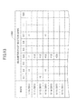
- FIG. 4 is a diagram illustrating an example of the kilometer post layout position information. It is noted that the kilometer post layout position information is classified on a vehicle road basis, and FIG. 4 is a diagram illustrating an example of the kilometer post layout position information 400 of “vehicle road A” among vehicle roads.
- the vehicle road A is 10 km long and includes 100 kilometer post sections.
- the names of the kilometer post sections included in the vehicle road A are stored.
- the names of the kilometer post sections are numbers, and in “kilometer post section name” the numbers corresponding to the names of the kilometer post sections are stored.
- the start point the combinations of the latitude and the longitude of the start points of the corresponding kilometer post sections identified by the “kilometer post section names” are stored. Further, in the “end point”, the combinations of the latitude and the longitude of the end points of the corresponding kilometer post sections identified by the “kilometer post section names” are stored. In the “end point” of the respective kilometer post sections, the same combinations of the latitude and the longitude as stored in the “start point” of the next kilometer post sections are stored. It is noted that, in FIG. 4 , a straight road is illustrated as an example for the sake of simplifying the explanation; however, the actual road is winding, and a kilometer post section includes a plurality of reference points in addition to the start and end points.
- the kilometer post section whose “kilometer post section name” is “0.2” corresponds to a section between the kilometer post located at 100 m from the start point of the vehicle road A and the kilometer post located at 200 m from the start point.
- the latitude and the longitude of the start point of the kilometer post section (i.e., the kilometer post located at 100 m from the start point) whose “kilometer post section name” is “0.2” is (a1, b1)
- the latitude and the longitude of the end point i.e., the kilometer post located at 200 m from the start point
- the latitudes and the longitudes of the start points and the end points are stored for the respective kilometer post sections until the kilometer post section whose “kilometer post section name” is “10.0”.
- FIG. 5 is a diagram illustrating an example of the MCI information stored in the server apparatus.
- the MCI information 500 includes, as items of information, “vehicle road name”, “kilometer post section name”, and “MCI value”.
- FIG. 6 is a diagram illustrating an example of the measurement information transmitted by the portable terminal.
- the measurement information 600 includes, as items of information, “date”, “time”, “latitude”, “longitude”, and “vertical acceleration”.
- a case is illustrated in which the latitude, the longitude, and the acceleration in the up-and-down direction are obtained every 0.5 sec.
- FIG. 7 is a diagram illustrating an example of evaluation value information.
- the evaluation value information 700 includes, as items of information, “road surface condition”, “evaluation value in case of being greater than or equal to a threshold value VTh1”, and “evaluation value in case of being greater than or equal to a threshold value VTh2”.
- the evaluation values in the case of being greater than or equal to a predetermined threshold value VTh1 are stored on a road surface condition-related-information item basis.
- the evaluation values in the case of being greater than or equal to a predetermined threshold value VTh2 are stored on a road surface condition-related-information item basis.
- the evaluation value “1” is derived when the prediction MCI value in a predetermined kilometer post section is in a range between 6 and 9 and the acceleration in the up-and-down direction is greater than or equal to the threshold value VTh1.
- the evaluation value “2” is derived when the prediction MCI value is in a range between 6 and 9 and the acceleration in the up-and-down direction is greater than or equal to the threshold value VTh2. It is noted that these evaluation values are referred to as a “reference evaluation value”.
- the evaluation value different from the reference evaluation value is derived. Further, in the case of the pot hole being there, the evaluation value different from the reference evaluation value is derived.
- FIG. 8 is a diagram illustrating an example of accumulation information.
- the accumulation information 800 includes, as items of information, “vehicle road name”, “kilometer post section name”, and “accumulation value”.
- FIG. 9 is a diagram for illustrating an example of prediction MCI information.
- the prediction MCI information 900 includes, as items of information, “kilometer post section name”, “start point”, “end point”, and “prediction MCI value”.
- the names of the kilometer post sections for which the prediction MCI values have been derived are stored.
- start point the combinations of the latitude and the longitude of the start points of the corresponding kilometer post sections identified by the “kilometer post section names” are stored.
- end point the combinations of the latitude and the longitude of the end points of the corresponding kilometer post sections identified by the “kilometer post section names” are stored.
- the prediction MCI values derived on a kilometer post basis are stored such that the prediction MCI values are associated with the corresponding kilometer post sections. It is noted that in the “prediction MCI value”, the MCI values in the respective kilometer post sections are stored as default settings.
- the server apparatus 210 has an MCI prediction program 230 installed therein.
- the server apparatus 210 implements functions of parts described hereinafter by the CPU 301 executing the MCI prediction program 230 .
- the evaluation value calculation part 1003 evaluates, based on the measurement information 600 obtained by the measurement information acquisition part 1002 , degradation levels of the road surfaces on a kilometer post section basis based on the kilometer post layout position information 400 stored in the kilometer post layout position information DB 241 , to derive the evaluation values. Specifically, the accelerations in the up-and-down direction included in the measurement information 600 are compared to the threshold values VTh1 and VTh2 on a kilometer post section basis. Then, if the acceleration in the up-and-down direction are greater than or equal to threshold value VTh1 or VTh2, the evaluation values are derived based on the evaluation value information 700 stored in the evaluation value information DB 244 .
- the evaluation value derived by the evaluation value calculation part 1003 based on the evaluation value information 700 has been adjusted according to the information relate to the road surface condition. Specifically, the evaluation value has been adjusted according to the prediction MCI value at the timing of deriving the evaluation value and the presence or absence of the pot hole.
- the evaluation value calculation part 1003 derives the evaluation values adjusted according to the information related to the road surface condition, which enables the server apparatus 210 to more earlier detect the kilometer post section whose road surface is degraded.
- the evaluation value calculation part 1003 deriving the value adjusted according to the information related to the road surface condition is equivalent to changing the detection sensitivity for detecting the kilometer post section whose road surface is degraded.
- the evaluation value value accumulation part 1004 calculates the accumulation value by adding the evaluation values derived by the evaluation value calculation part 1003 on a kilometer post section basis, generates the accumulation information 800 including the accumulation values of the kilometer post sections, and stores the accumulation information 800 in the accumulation information DB 245 .
- the prediction MCI value calculation part 1005 calculates, based on the accumulation information 800 stored in the accumulation information DB 245 , the prediction MCI value on a kilometer post section basis. Specifically, at first, the accumulation value stored on a kilometer post section basis in the accumulation information 800 is divided by an evaluation reference value to obtain a quotient thereof. Then, the prediction MCI value is calculated on a kilometer post section basis by subtracting the quotient from the MCI value for the corresponding kilometer post section included in the MCI information 500 .
- the evaluation reference value is “20”
- the accumulation value is “30” for the kilometer post whose “kilometer post name” is “0.4”
- the quotient obtained by dividing the accumulation by the evaluation reference value is “1”.
- the MCI value is “7” for the kilometer post whose “kilometer post name” is “0.4”
- the prediction MCI value calculation part 1005 generates the prediction MCI information 900 in which the prediction MCI values are associated with the kilometer post sections to store the prediction MCI information 900 in the prediction MCI information DB 246 .
- the prediction MCI information output part 1006 outputs the prediction MCI information 900 stored in the prediction MCI information DB 246 to a recording medium, for example.
- FIG. 11 is a flowchart of a prediction MCI information generation process executed in the server apparatus 210 .
- the flowchart illustrated in FIG. 11 is performed on a kilometer post section basis. It is noted that the MCI information 500 has been stored in the MCI information DB 242 before executing the flowchart illustrated in FIG. 11 .
- step S 1102 if it is determined that the measurement information 600 with respect to the target kilometer post section has been transmitted from the portable terminal 221 , the measurement information acquisition part 1002 obtains the measurement information 600 with respect to the target kilometer post section. Further, in step S 1103 , the measurement information acquisition part 1002 stores the obtained measurement information 600 of the target kilometer post section in the measurement information DB 243 .
- step S 1104 the evaluation value calculation part 1003 compares the accelerations in the up-and-down direction, which are included in the obtained measurement information 600 of the target kilometer post section, to the thresholds VTh1 and VTh2.
- step S 1106 the evaluation value value accumulation part 1004 adds the evaluation value E derived in step S 1105 to the accumulation value S to update the accumulation value S.
- step S 1107 the evaluation value accumulation part 1004 stores the updated accumulation S calculated in step S 1106 in the target kilometer post in the accumulation information 800 .
- step S 1109 the prediction MCI value calculation part 1005 calculates the prediction MCI value by subtracting the quotient from the MCI value of the target kilometer post section in the MCI information 500 .
- step S 1110 the prediction MCI value calculation part 1005 stores the prediction MCI value calculated in step S 1109 in the prediction MCI information DB 246 .
- step S 1111 the evaluation value accumulation part 1004 determines whether the repair of the road surface with respect to the target kilometer post section has been performed. If it is determined in step S 1111 that the repair of the road surface with respect to the target kilometer post section has been performed, the process goes to step S 1112 where 0 is inserted in the accumulation value S of the target kilometer post section to return to step S 1102 . In other words, if the repair of the road surface has been performed, the accumulation value S is reset and the processes from step S 1102 through step S 1111 are repeated.
- step S 1111 if it is determined in step S 1111 that the repair of the road surface with respect to the target kilometer post section has not been performed, the process returns to step S 1102 to repeat the processes from step S 1102 through step S 1111 .
- step S 1104 in which the comparison between the measurement information and the threshold values VTh1, VTh2 is performed on a kilometer post section basis, and the process of step S 1105 in which the evaluation is derived, are explained with reference to FIG. 12 and FIG. 13 .
- the acceleration in the up-and-down direction from the kilometer post section whose “kilometer post section name” is “0.1” to the kilometer post section whose “kilometer post section name” is “0.3” in the vehicle road A is illustrated.
- the process of the up-and-down acceleration values 1200 is described in the case where the kilometer post section whose “kilometer post section name” is “0.1” is the target kilometer post section.
- the evaluation value for the kilometer post section whose “kilometer post section name” is “0.1” is derived according to the information related to the road surface state from the “evaluation value in case of being greater than or equal to a threshold value VTh2” of the evaluation value information 700 .
- FIG. 13 is a diagram illustrating such an accumulation process in which the evaluations thus derived for the respective kilometer post sections are accumulated on a kilometer post basis every time when the measurement information is obtained. As illustrated in FIG. 13 , the evaluation values for the kilometer post sections are derived every time when the measurement information is obtained. It is noted that blanks in FIG. 13 indicate that, as a result of the comparison between the up-and-down acceleration values 1200 and the threshold values VTh1 and VTh2, the acceleration in the up-and-down direction greater than or equal to the threshold value VTh1 or VTh2 has not been detected.
- the acceleration in the up-and-down direction in the kilometer post section whose “kilometer post section name” is “0.1”, among the acceleration in the up-and-down direction obtained on “date” “2013 Mar. 12”, includes the acceleration in the up-and-down direction greater than or equal to the threshold value VTh2.
- step S 1106 the processes from the calculation of the accumulation value S (step S 1106 ) to the determination that the repair of the road surface has been performed (Yes in step S 1111 ) are specifically explained with reference to FIG. 14 .
- FIG. 14 is a diagram illustrating a change in the accumulation value S in the kilometer post section whose “kilometer post section name” is “0.4”.
- the evaluation value is added, which causes the accumulation value S to increase with the passage of time.
- the evaluation value calculation part 1003 adjusts the evaluation value to increase the detection sensitivity (from 1 to 1.2) for detecting the kilometer post section in which the road surface has been degraded, and increases a gradient of the increase of the accumulation value S after the detection of the pot hole in comparison with that before the detection of the pot hole.
- the evaluation value calculation part 1003 adjusts the evaluation value to further increase the detection sensitivity (from 1.2 to 2.3) for detecting the kilometer post section in which the road surface has been degraded, and further increases the gradient of the increase of the accumulation value S.
- the evaluation value calculation part 1003 adjusts the evaluation value to further increase the detection sensitivity (from 2.3 to 2.5) for detecting the kilometer post section in which the road surface has been degraded, and further increases the gradient of the increase of the accumulation value S.
- the road surface condition measurement vehicle 110 performs the road surface condition measurement with respect to the kilometer post section whose “kilometer post section name” is “0.4” to derive the MCI value. Further, the repair work of the road surface based on the derived MCI value is performed. As a result of this, the accumulation value S is reset.
- the road surface condition measurement is performed with respect to the vehicle road as a whole to be inspected, and after the MCI value has been derived, the prediction MCI values are calculated based on the measurement information at a plurality of times of the measurement with the portable terminal 221 .
- the evaluation value according to the information related to the road surface condition is used to calculate the prediction MCI value based on the measurement information at a plurality of times.
- the measurement target of the road surface condition measurement is limited by calculating the prediction MCI value on a kilometer post section basis.
- the cost related to the inspection can be cut with respect to the case where the vehicle road as a whole to be inspected is subject to the measurement with the road surface condition measurement vehicle and the calculation of the MCI values.
- the evaluation value calculation part 1003 amplifies the acceleration in the up-and-down direction included in the measurement information 600 based on the information related to the road surface condition at present in order to increase the detection sensitivity for detecting the kilometer post section in which the road surface is degraded.
- This arrangement increases the probability that it is determined that the acceleration in the up-and-down direction greater than or equal to the threshold value VTh1 or VTh2 has been detected, which enables increasing the gradient of the increase of the accumulation value S.
- FIG. 15 is a flowchart of the prediction MCI information generation process executed in the server apparatus 210 . It is noted that, among the respective processes in the flowchart illustrated in FIG. 15 , the same processes as those of the flowchart illustrated in FIG. 11 are given the same reference numerals, and explanation thereof is omitted. Different points with respect to FIG. 11 are related to step S 1501 and step S 1502 .
- step S 1502 the evaluation value calculation part 1003 compares the converted acceleration in the up-and-down direction of the target kilometer post section to the thresholds VTh1 and VTh2. Further, as the result of the comparison, if it is determined that the converted acceleration in the up-and-down direction of the target kilometer post section includes the acceleration greater than or equal to the threshold value VTh1, the evaluation value calculation part 1003 derives the evaluation value “1”. Further, as the result of the comparison, if it is determined that the converted acceleration in the up-and-down direction of the target kilometer post section includes the acceleration greater than or equal to the threshold value VTh2, the evaluation value calculation part 1003 derives the evaluation value “2”.
- the acceleration in the up-and-down direction included in the measurement information 600 is amplified based on the information related to the road surface state at present, which enables increasing the detection sensitivity for detecting the kilometer post section in which the road surface is degraded.
- the evaluation values are derived from the converted acceleration in the up-and-down direction in the target kilometer post section, and the evaluation values are accumulated to calculate the accumulation value.
- the converted acceleration itself in the up-and-down direction in the target kilometer post section may be accumulated to calculate the accumulation value and then derive the prediction MCI value.
- the measurement information may be accumulated or the evaluations derived based on the measurement information may be accumulated.
- the prediction MCI information output part 1006 separately outputs, among the prediction MCI values included in the prediction MCI information, the prediction MCI value of the kilometer post section for which the number of the acquisition of the measurement information is small, and prediction MCI value of the kilometer post section for which the number of the acquisition of the measurement information is great.
- FIG. 16 is a diagram illustrating another example of the prediction MCI information.
- FIG. 16 is a diagram illustrating an example of the prediction MCI information output by the prediction MCI information output part 1006 according to the third embodiment.
- the “prediction MCI value” includes the kilometer post sections for which the prediction MCI values are stored, and the kilometer post sections for which predetermined messages (“low reliability”) are stored.
- the kilometer post sections for which the prediction MCI values are stored in the “prediction MCI value” indicates that, with respect to such kilometer post sections, the travel with the patrol vehicle 120 has been performed at a plurality of times, and the measurement information has been obtained at a plurality of times. Thus, if the prediction MCI value does not change with respect to the default MCI value, it can be determined that the road surface is not degraded.
- a navigation system installed in an ordinary vehicle is coupled to a network. Further, the prediction MCI information output part according to the fourth embodiment instructs the alarm output for the navigation system installed in an ordinary vehicle based on the prediction MCI information.
- FIG. 17 is a diagram illustrating another example of a system configuration of the measurement system of the road surface state. It is noted that, here, the explanation is focused on the difference with respect to the measurement system 200 of the road surface state according to the first embodiment described above with reference to FIG. 2 .
- the measurement system 1700 of the road surface state includes an ordinary vehicle 1720 .
- the ordinary vehicle 1720 is owned by a user who utilizes the prediction MCI information.
- the navigation system 1721 is installed in the ordinary vehicle 1720 in which the navigation system 1721 electronically determines the current position and routes to destinations during the travel of the ordinary vehicle 1720 .
- the navigation system 1721 transmits the latitude and the longitude indicative of the current position to a server apparatus 1710 , and outputs the alarm when an alarm instruction based on the prediction MCI information from the server apparatus 1710 is received.
- FIG. 18 is a flowchart of an alarm process executed in the server apparatus 1710 .
- the alarm process illustrated in FIG. 18 is performed during a period in which the navigation system 1721 is in operation.
- step S 1801 the prediction MCI information output part 1006 receives the latitude and the longitude indicative of the current position from the navigation system 1721 .
- step S 1802 the prediction MCI information output part 1006 identifies the kilometer post section(s) whose prediction MCI value(s) included in the prediction MCI information is less than or equal to 3, and determines whether the current position received by the navigation system 1721 is included in the identified kilometer post section.
- step S 1802 if it is determined that the current position received by the navigation system 1721 is included in the identified kilometer post section, the process goes to step S 1803 .
- step S 1803 the prediction MCI information output part 1006 instructs the navigation system 1721 to output the alarm indicative of the travel on the kilometer post section in which the road surface is degraded, and then goes to step S 1804 .
- step S 1802 determines that the current position received by the navigation system 1721 is not included in the identified kilometer post section. If it is determined in step S 1802 that the current position received by the navigation system 1721 is not included in the identified kilometer post section, the process directly goes to step S 1804 .
- the accumulation value is calculated every time when the measurement information is obtained; however, the accumulation value may be calculated after the measurement information at predetermined times has been obtained.
- the server apparatus 210 stores the information illustrated in FIG. 13 . Further, the server apparatus 210 also stores the kilometer post section for which the repair has been performed and the date and time of the repair. Further, in calculating the accumulation value, the server apparatus 210 performs accumulation of the evaluation values derived based on the measurement information obtained after the date and time of the repair.
Landscapes
- Engineering & Computer Science (AREA)
- Architecture (AREA)
- Civil Engineering (AREA)
- Structural Engineering (AREA)
- Mining & Mineral Resources (AREA)
- Road Repair (AREA)
- Traffic Control Systems (AREA)
- Navigation (AREA)
Applications Claiming Priority (3)
| Application Number | Priority Date | Filing Date | Title |
|---|---|---|---|
| JP2014-055518 | 2014-03-18 | ||
| JP2014055518A JP6343987B2 (ja) | 2014-03-18 | 2014-03-18 | 路面劣化検出方法、情報処理装置及びプログラム |
| PCT/JP2015/057364 WO2015141559A1 (ja) | 2014-03-18 | 2015-03-12 | 路面劣化検出方法、情報処理装置及びプログラム |
Related Parent Applications (1)
| Application Number | Title | Priority Date | Filing Date |
|---|---|---|---|
| PCT/JP2015/057364 Continuation WO2015141559A1 (ja) | 2014-03-18 | 2015-03-12 | 路面劣化検出方法、情報処理装置及びプログラム |
Publications (2)
| Publication Number | Publication Date |
|---|---|
| US20160356002A1 US20160356002A1 (en) | 2016-12-08 |
| US10011960B2 true US10011960B2 (en) | 2018-07-03 |
Family
ID=54144529
Family Applications (1)
| Application Number | Title | Priority Date | Filing Date |
|---|---|---|---|
| US15/237,858 Expired - Fee Related US10011960B2 (en) | 2014-03-18 | 2016-08-16 | Method of detecting road surface degradation, information process apparatus, and non-transitory computer-readable recording medium |
Country Status (6)
| Country | Link |
|---|---|
| US (1) | US10011960B2 (ja) |
| JP (1) | JP6343987B2 (ja) |
| CN (1) | CN106062843A (ja) |
| PH (1) | PH12016501695A1 (ja) |
| SG (1) | SG11201606916SA (ja) |
| WO (1) | WO2015141559A1 (ja) |
Cited By (1)
| Publication number | Priority date | Publication date | Assignee | Title |
|---|---|---|---|---|
| US20220126642A1 (en) * | 2020-10-23 | 2022-04-28 | Toyota Jidosha Kabushiki Kaisha | Road surface information producing apparatus and vehicle control system |
Families Citing this family (14)
| Publication number | Priority date | Publication date | Assignee | Title |
|---|---|---|---|---|
| JP6704817B2 (ja) * | 2016-08-18 | 2020-06-03 | 西日本高速道路エンジニアリング四国株式会社 | 排水性舗装におけるポットホール発生リスクを定量分析する方法 |
| WO2018066118A1 (ja) * | 2016-10-06 | 2018-04-12 | 富士通株式会社 | 道路状態の管理プログラム、道路状態の管理装置、及び道路状態の管理方法 |
| JP6848321B2 (ja) * | 2016-10-06 | 2021-03-24 | 富士通株式会社 | 路面状況検出プログラム及び路面状況検出装置 |
| WO2018066116A1 (ja) * | 2016-10-06 | 2018-04-12 | 富士通株式会社 | 道路状態の管理プログラム、道路状態の管理装置、及び道路状態の管理方法 |
| JP6620720B2 (ja) * | 2016-11-04 | 2019-12-18 | 株式会社デンソー | 路面状態判定システム |
| CN106592394B (zh) * | 2016-11-17 | 2018-11-06 | 长安大学 | 一种自发电式道路寿命检测无线传感系统及其检测方法 |
| JP6694113B2 (ja) * | 2017-03-31 | 2020-05-13 | 日立建機株式会社 | 路面管理システムおよび路面管理方法 |
| US10846819B2 (en) * | 2017-04-12 | 2020-11-24 | Southern Methodist University | Method and apparatus to infer structural stresses with visual image and video data |
| JP6604461B2 (ja) * | 2017-05-19 | 2019-11-13 | 株式会社村田製作所 | 警告システム、コンピュータプログラム、及び警告方法 |
| CN108417065B (zh) * | 2018-03-21 | 2020-09-29 | 成都雅骏汽车制造有限公司 | 一种基于智能手机和导航应用的坑洼路面预警方法 |
| CN109151060A (zh) * | 2018-09-28 | 2019-01-04 | 广州小鹏汽车科技有限公司 | 一种路面异常监测方法、装置及计算机可读存储介质 |
| JP7211349B2 (ja) | 2019-11-29 | 2023-01-24 | トヨタ自動車株式会社 | 路面損傷検出装置、路面損傷検出方法、プログラム |
| JP7306362B2 (ja) * | 2020-10-19 | 2023-07-11 | トヨタ自動車株式会社 | 車両のプレビュー制振制御用データベース作成方法 |
| US20240175680A1 (en) * | 2021-03-26 | 2024-05-30 | Nec Corporation | Road inspection system, measurement vehicle, server, road inspection method, and program recording medium |
Citations (14)
| Publication number | Priority date | Publication date | Assignee | Title |
|---|---|---|---|---|
| JPH01108595A (ja) | 1987-10-22 | 1989-04-25 | Nichireki Chem Ind Co Ltd | 道路の路面特性図の作成方法 |
| US4896964A (en) * | 1986-10-10 | 1990-01-30 | Tokyo Keiki Co., Ltd. | System for measuring irregularities of road surface |
| JP2003288665A (ja) | 2002-03-27 | 2003-10-10 | Fujitsu Fip Corp | 交通量感知器を用いた路面性状推定方法とシステム |
| JP2005138839A (ja) | 2005-01-24 | 2005-06-02 | Toyota Central Res & Dev Lab Inc | 路面判定装置 |
| JP2007329762A (ja) | 2006-06-08 | 2007-12-20 | Fujitsu Ten Ltd | 物体候補領域検出装置、物体候補領域検出方法、歩行者認識装置、および車両制御装置 |
| JP2008297764A (ja) | 2007-05-30 | 2008-12-11 | Fuji Electric Systems Co Ltd | 道路情報管理装置 |
| US20130170701A1 (en) | 2011-12-28 | 2013-07-04 | Fujitsu Limited | Computer-readable recording medium and road surface survey device |
| US20130238164A1 (en) * | 2012-03-12 | 2013-09-12 | Nissan Motor Co., Ltd. | Road surface slope estimating device |
| JP2014038448A (ja) | 2012-08-15 | 2014-02-27 | Ntt Docomo Inc | サーバ装置、課金システム、プログラムおよび動作方法 |
| US20160167669A1 (en) * | 2014-12-12 | 2016-06-16 | GM Global Technology Operations LLC | Systems and methods for determining a condition of a road surface |
| US20160201277A1 (en) * | 2014-06-09 | 2016-07-14 | Nira Dynamics Ab | Detection of short term irregularities in a road surface |
| US20160258118A1 (en) * | 2014-03-19 | 2016-09-08 | Komatsu Ltd. | Road Surface Condition Determining Method, Road Surface Condition Outputting Method, Road Surface Condition Determining Device and Road Surface Condition Output Equipment |
| US20160356001A1 (en) * | 2014-03-18 | 2016-12-08 | Fujitsu Limited | Method of measuring road state, method of identifying degradation point of road surface, information process apparatus, and non-transitory computer-readable recording medium |
| US20170282869A1 (en) * | 2016-03-30 | 2017-10-05 | GM Global Technology Operations LLC | Road surface condition detection with multi-scale fusion |
Family Cites Families (2)
| Publication number | Priority date | Publication date | Assignee | Title |
|---|---|---|---|---|
| JP2001004382A (ja) * | 1999-06-23 | 2001-01-12 | Matsushita Electric Ind Co Ltd | 車載ナビゲーション装置及び道路情報通信システム |
| JP5618744B2 (ja) * | 2010-05-26 | 2014-11-05 | 三菱電機株式会社 | 道路形状推定装置及びコンピュータプログラム及び道路形状推定方法 |
-
2014
- 2014-03-18 JP JP2014055518A patent/JP6343987B2/ja active Active
-
2015
- 2015-03-12 SG SG11201606916SA patent/SG11201606916SA/en unknown
- 2015-03-12 CN CN201580011356.8A patent/CN106062843A/zh active Pending
- 2015-03-12 WO PCT/JP2015/057364 patent/WO2015141559A1/ja active Application Filing
-
2016
- 2016-08-16 US US15/237,858 patent/US10011960B2/en not_active Expired - Fee Related
- 2016-08-26 PH PH12016501695A patent/PH12016501695A1/en unknown
Patent Citations (15)
| Publication number | Priority date | Publication date | Assignee | Title |
|---|---|---|---|---|
| US4896964A (en) * | 1986-10-10 | 1990-01-30 | Tokyo Keiki Co., Ltd. | System for measuring irregularities of road surface |
| JPH01108595A (ja) | 1987-10-22 | 1989-04-25 | Nichireki Chem Ind Co Ltd | 道路の路面特性図の作成方法 |
| JP2003288665A (ja) | 2002-03-27 | 2003-10-10 | Fujitsu Fip Corp | 交通量感知器を用いた路面性状推定方法とシステム |
| JP2005138839A (ja) | 2005-01-24 | 2005-06-02 | Toyota Central Res & Dev Lab Inc | 路面判定装置 |
| JP2007329762A (ja) | 2006-06-08 | 2007-12-20 | Fujitsu Ten Ltd | 物体候補領域検出装置、物体候補領域検出方法、歩行者認識装置、および車両制御装置 |
| JP2008297764A (ja) | 2007-05-30 | 2008-12-11 | Fuji Electric Systems Co Ltd | 道路情報管理装置 |
| US20130170701A1 (en) | 2011-12-28 | 2013-07-04 | Fujitsu Limited | Computer-readable recording medium and road surface survey device |
| JP2013139671A (ja) | 2011-12-28 | 2013-07-18 | Fujitsu Ltd | 路面調査プログラム及び路面調査装置 |
| US20130238164A1 (en) * | 2012-03-12 | 2013-09-12 | Nissan Motor Co., Ltd. | Road surface slope estimating device |
| JP2014038448A (ja) | 2012-08-15 | 2014-02-27 | Ntt Docomo Inc | サーバ装置、課金システム、プログラムおよび動作方法 |
| US20160356001A1 (en) * | 2014-03-18 | 2016-12-08 | Fujitsu Limited | Method of measuring road state, method of identifying degradation point of road surface, information process apparatus, and non-transitory computer-readable recording medium |
| US20160258118A1 (en) * | 2014-03-19 | 2016-09-08 | Komatsu Ltd. | Road Surface Condition Determining Method, Road Surface Condition Outputting Method, Road Surface Condition Determining Device and Road Surface Condition Output Equipment |
| US20160201277A1 (en) * | 2014-06-09 | 2016-07-14 | Nira Dynamics Ab | Detection of short term irregularities in a road surface |
| US20160167669A1 (en) * | 2014-12-12 | 2016-06-16 | GM Global Technology Operations LLC | Systems and methods for determining a condition of a road surface |
| US20170282869A1 (en) * | 2016-03-30 | 2017-10-05 | GM Global Technology Operations LLC | Road surface condition detection with multi-scale fusion |
Non-Patent Citations (11)
| Title |
|---|
| Espacenet Bibliographic Data, Japanese Publication No. 1-108595, published Apr. 25, 1989. |
| Espacenet Bibliographic Data, Japanese Publication No. 2003-288665, published Oct. 10, 2003. |
| Espacenet Bibliographic Data, Japanese Publication No. 2005-138839, published Jun. 2, 2005. |
| Espacenet Bibliographic Data, Japanese Publication No. 2007-329762, published Dec. 20, 2007. |
| Espacenet Bibliographic Data, Japanese Publication No. 2008-297764, published Dec. 11, 2008. |
| International Search Report dated Jun. 16, 2015 in corresponding International Application No. PCT/JP2015/057364**. |
| Japanese Platform for Patent Information, Publication No. 2013-139671, published Jul. 18, 2013. |
| Japanese Platform for Patent Information, Publication No. 2014-38448, published Feb. 27, 2014. |
| Office Action for corresponding Chinese Patent Application No. 201580011356.8, dated Feb. 5, 2018. |
| Office Action for corresponding Japanese Patent Application No. 2014-055518, dated Oct. 31, 2017. |
| Written Opinion of the International Searching Authority dated Jun. 16, 2015 in corresponding International Application No. PCT/JP2014/057364. |
Cited By (2)
| Publication number | Priority date | Publication date | Assignee | Title |
|---|---|---|---|---|
| US20220126642A1 (en) * | 2020-10-23 | 2022-04-28 | Toyota Jidosha Kabushiki Kaisha | Road surface information producing apparatus and vehicle control system |
| US11807063B2 (en) * | 2020-10-23 | 2023-11-07 | Toyota Jidosha Kabushiki Kaisha | Road surface information producing apparatus and vehicle control system |
Also Published As
| Publication number | Publication date |
|---|---|
| WO2015141559A1 (ja) | 2015-09-24 |
| US20160356002A1 (en) | 2016-12-08 |
| SG11201606916SA (en) | 2016-09-29 |
| PH12016501695A1 (en) | 2016-10-03 |
| CN106062843A (zh) | 2016-10-26 |
| JP2015178702A (ja) | 2015-10-08 |
| JP6343987B2 (ja) | 2018-06-20 |
Similar Documents
| Publication | Publication Date | Title |
|---|---|---|
| US10011960B2 (en) | Method of detecting road surface degradation, information process apparatus, and non-transitory computer-readable recording medium | |
| US20160356001A1 (en) | Method of measuring road state, method of identifying degradation point of road surface, information process apparatus, and non-transitory computer-readable recording medium | |
| US9273968B2 (en) | Track information generating device, track information generating method, and computer-readable storage medium | |
| US20180165525A1 (en) | Traveling lane determining device and traveling lane determining method | |
| KR102371984B1 (ko) | 도로 변경 지점 검출 방법 | |
| KR20100100842A (ko) | 디지털 맵의 검증 | |
| US10803751B2 (en) | Processing device | |
| JP2015138316A (ja) | 特異走行箇所検出装置及び特異走行箇所検出方法 | |
| US11408739B2 (en) | Location correction utilizing vehicle communication networks | |
| US11421995B2 (en) | Map matching device, map matching system, map matching method and program | |
| WO2014132432A1 (ja) | 車両位置表示制御装置および車両位置特定プログラム | |
| US10023211B2 (en) | Train position detecting device | |
| KR101553898B1 (ko) | 지형지물의 위치정보를 이용한 자율이동차량의 위치추정시스템 및 방법 | |
| KR102428765B1 (ko) | 터널 조명을 이용한 자율주행 차량 항법 시스템 | |
| CN110208823A (zh) | 确定用于基于卫星确定车辆位置的数据简档的方法 | |
| WO2013008888A1 (ja) | 位置通知装置及び車両位置通知方法、並びに車載器、車両位置算出方法及びプログラム、並びに車両位置算出システム | |
| WO2019174045A1 (en) | Method and device for locating fault point in area network based on traveling wave | |
| CN114274972A (zh) | 自主驾驶环境中的场景识别 | |
| WO2019171821A1 (ja) | 列車位置推定装置 | |
| US11423782B2 (en) | Traffic status estimation device, traffic status estimation method, and program recording medium | |
| US20200363214A1 (en) | Method for using a feature-based localization map for a vehicle | |
| CN114968187A (zh) | 用于自动驾驶系统的感知系统开发的平台 | |
| US20190100174A1 (en) | Speed control device | |
| KR20210006143A (ko) | 교통 정보 제공 시스템 및 방법 | |
| JP5728751B2 (ja) | 交通案内情報生成装置、交通案内情報生成方法および交通案内情報生成プログラム |
Legal Events
| Date | Code | Title | Description |
|---|---|---|---|
| AS | Assignment |
Owner name: FUJITSU LIMITED, JAPAN Free format text: ASSIGNMENT OF ASSIGNORS INTEREST;ASSIGNOR:TANI, HIROYUKI;REEL/FRAME:039707/0739 Effective date: 20160725 |
|
| STCF | Information on status: patent grant |
Free format text: PATENTED CASE |
|
| FEPP | Fee payment procedure |
Free format text: MAINTENANCE FEE REMINDER MAILED (ORIGINAL EVENT CODE: REM.); ENTITY STATUS OF PATENT OWNER: LARGE ENTITY |
|
| LAPS | Lapse for failure to pay maintenance fees |
Free format text: PATENT EXPIRED FOR FAILURE TO PAY MAINTENANCE FEES (ORIGINAL EVENT CODE: EXP.); ENTITY STATUS OF PATENT OWNER: LARGE ENTITY |
|
| STCH | Information on status: patent discontinuation |
Free format text: PATENT EXPIRED DUE TO NONPAYMENT OF MAINTENANCE FEES UNDER 37 CFR 1.362 |
|
| FP | Lapsed due to failure to pay maintenance fee |
Effective date: 20220703 |