TWI704591B - Drawing data creation method - Google Patents

Drawing data creation method Download PDF

Info

Publication number
TWI704591B
TWI704591B TW107104955A TW107104955A TWI704591B TW I704591 B TWI704591 B TW I704591B TW 107104955 A TW107104955 A TW 107104955A TW 107104955 A TW107104955 A TW 107104955A TW I704591 B TWI704591 B TW I704591B
Authority
TW
Taiwan
Prior art keywords
trapezoid
dose
drawing data
data
aforementioned
Prior art date
Application number
TW107104955A
Other languages
Chinese (zh)
Other versions
TW201837965A (en
Inventor
原重博
安井健一
加藤靖雄
Original Assignee
日商紐富來科技股份有限公司
Priority date (The priority date is an assumption and is not a legal conclusion. Google has not performed a legal analysis and makes no representation as to the accuracy of the date listed.)
Filing date
Publication date
Application filed by 日商紐富來科技股份有限公司 filed Critical 日商紐富來科技股份有限公司
Publication of TW201837965A publication Critical patent/TW201837965A/en
Application granted granted Critical
Publication of TWI704591B publication Critical patent/TWI704591B/en

Links

Images

Classifications

    • GPHYSICS
    • G06COMPUTING; CALCULATING OR COUNTING
    • G06FELECTRIC DIGITAL DATA PROCESSING
    • G06F30/00Computer-aided design [CAD]
    • G06F30/30Circuit design
    • G06F30/39Circuit design at the physical level
    • G06F30/392Floor-planning or layout, e.g. partitioning or placement
    • GPHYSICS
    • G06COMPUTING; CALCULATING OR COUNTING
    • G06TIMAGE DATA PROCESSING OR GENERATION, IN GENERAL
    • G06T11/002D [Two Dimensional] image generation
    • G06T11/20Drawing from basic elements, e.g. lines or circles
    • G06T11/206Drawing of charts or graphs
    • GPHYSICS
    • G03PHOTOGRAPHY; CINEMATOGRAPHY; ANALOGOUS TECHNIQUES USING WAVES OTHER THAN OPTICAL WAVES; ELECTROGRAPHY; HOLOGRAPHY
    • G03FPHOTOMECHANICAL PRODUCTION OF TEXTURED OR PATTERNED SURFACES, e.g. FOR PRINTING, FOR PROCESSING OF SEMICONDUCTOR DEVICES; MATERIALS THEREFOR; ORIGINALS THEREFOR; APPARATUS SPECIALLY ADAPTED THEREFOR
    • G03F7/00Photomechanical, e.g. photolithographic, production of textured or patterned surfaces, e.g. printing surfaces; Materials therefor, e.g. comprising photoresists; Apparatus specially adapted therefor
    • G03F7/70Microphotolithographic exposure; Apparatus therefor
    • G03F7/70483Information management; Active and passive control; Testing; Wafer monitoring, e.g. pattern monitoring
    • G03F7/70491Information management, e.g. software; Active and passive control, e.g. details of controlling exposure processes or exposure tool monitoring processes
    • G03F7/70508Data handling in all parts of the microlithographic apparatus, e.g. handling pattern data for addressable masks or data transfer to or from different components within the exposure apparatus
    • HELECTRICITY
    • H01ELECTRIC ELEMENTS
    • H01JELECTRIC DISCHARGE TUBES OR DISCHARGE LAMPS
    • H01J37/00Discharge tubes with provision for introducing objects or material to be exposed to the discharge, e.g. for the purpose of examination or processing thereof
    • H01J37/30Electron-beam or ion-beam tubes for localised treatment of objects
    • H01J37/302Controlling tubes by external information, e.g. programme control
    • H01J37/3023Programme control
    • H01J37/3026Patterning strategy
    • GPHYSICS
    • G03PHOTOGRAPHY; CINEMATOGRAPHY; ANALOGOUS TECHNIQUES USING WAVES OTHER THAN OPTICAL WAVES; ELECTROGRAPHY; HOLOGRAPHY
    • G03FPHOTOMECHANICAL PRODUCTION OF TEXTURED OR PATTERNED SURFACES, e.g. FOR PRINTING, FOR PROCESSING OF SEMICONDUCTOR DEVICES; MATERIALS THEREFOR; ORIGINALS THEREFOR; APPARATUS SPECIALLY ADAPTED THEREFOR
    • G03F7/00Photomechanical, e.g. photolithographic, production of textured or patterned surfaces, e.g. printing surfaces; Materials therefor, e.g. comprising photoresists; Apparatus specially adapted therefor
    • G03F7/0002Lithographic processes using patterning methods other than those involving the exposure to radiation, e.g. by stamping
    • GPHYSICS
    • G03PHOTOGRAPHY; CINEMATOGRAPHY; ANALOGOUS TECHNIQUES USING WAVES OTHER THAN OPTICAL WAVES; ELECTROGRAPHY; HOLOGRAPHY
    • G03FPHOTOMECHANICAL PRODUCTION OF TEXTURED OR PATTERNED SURFACES, e.g. FOR PRINTING, FOR PROCESSING OF SEMICONDUCTOR DEVICES; MATERIALS THEREFOR; ORIGINALS THEREFOR; APPARATUS SPECIALLY ADAPTED THEREFOR
    • G03F7/00Photomechanical, e.g. photolithographic, production of textured or patterned surfaces, e.g. printing surfaces; Materials therefor, e.g. comprising photoresists; Apparatus specially adapted therefor
    • G03F7/20Exposure; Apparatus therefor
    • HELECTRICITY
    • H01ELECTRIC ELEMENTS
    • H01JELECTRIC DISCHARGE TUBES OR DISCHARGE LAMPS
    • H01J37/00Discharge tubes with provision for introducing objects or material to be exposed to the discharge, e.g. for the purpose of examination or processing thereof
    • H01J37/30Electron-beam or ion-beam tubes for localised treatment of objects
    • H01J37/317Electron-beam or ion-beam tubes for localised treatment of objects for changing properties of the objects or for applying thin layers thereon, e.g. for ion implantation
    • H01J37/3174Particle-beam lithography, e.g. electron beam lithography
    • H01J37/3177Multi-beam, e.g. fly's eye, comb probe
    • HELECTRICITY
    • H01ELECTRIC ELEMENTS
    • H01LSEMICONDUCTOR DEVICES NOT COVERED BY CLASS H10
    • H01L21/00Processes or apparatus adapted for the manufacture or treatment of semiconductor or solid state devices or of parts thereof
    • H01L21/02Manufacture or treatment of semiconductor devices or of parts thereof
    • H01L21/027Making masks on semiconductor bodies for further photolithographic processing not provided for in group H01L21/18 or H01L21/34
    • H01L21/0271Making masks on semiconductor bodies for further photolithographic processing not provided for in group H01L21/18 or H01L21/34 comprising organic layers
    • H01L21/0273Making masks on semiconductor bodies for further photolithographic processing not provided for in group H01L21/18 or H01L21/34 comprising organic layers characterised by the treatment of photoresist layers
    • H01L21/0277Electrolithographic processes
    • HELECTRICITY
    • H01ELECTRIC ELEMENTS
    • H01JELECTRIC DISCHARGE TUBES OR DISCHARGE LAMPS
    • H01J2237/00Discharge tubes exposing object to beam, e.g. for analysis treatment, etching, imaging
    • H01J2237/30Electron or ion beam tubes for processing objects
    • H01J2237/317Processing objects on a microscale
    • H01J2237/3175Lithography
    • H01J2237/31761Patterning strategy
    • H01J2237/31762Computer and memory organisation
    • HELECTRICITY
    • H01ELECTRIC ELEMENTS
    • H01JELECTRIC DISCHARGE TUBES OR DISCHARGE LAMPS
    • H01J2237/00Discharge tubes exposing object to beam, e.g. for analysis treatment, etching, imaging
    • H01J2237/30Electron or ion beam tubes for processing objects
    • H01J2237/317Processing objects on a microscale
    • H01J2237/3175Lithography
    • H01J2237/31761Patterning strategy
    • H01J2237/31764Dividing into sub-patterns
    • HELECTRICITY
    • H01ELECTRIC ELEMENTS
    • H01JELECTRIC DISCHARGE TUBES OR DISCHARGE LAMPS
    • H01J2237/00Discharge tubes exposing object to beam, e.g. for analysis treatment, etching, imaging
    • H01J2237/30Electron or ion beam tubes for processing objects
    • H01J2237/317Processing objects on a microscale
    • H01J2237/3175Lithography
    • H01J2237/31769Proximity effect correction

Landscapes

  • Engineering & Computer Science (AREA)
  • Physics & Mathematics (AREA)
  • General Physics & Mathematics (AREA)
  • Analytical Chemistry (AREA)
  • Chemical & Material Sciences (AREA)
  • Computer Hardware Design (AREA)
  • Theoretical Computer Science (AREA)
  • Manufacturing & Machinery (AREA)
  • Condensed Matter Physics & Semiconductors (AREA)
  • Microelectronics & Electronic Packaging (AREA)
  • Power Engineering (AREA)
  • General Engineering & Computer Science (AREA)
  • Geometry (AREA)
  • Evolutionary Computation (AREA)
  • Architecture (AREA)
  • Electron Beam Exposure (AREA)
  • Exposure And Positioning Against Photoresist Photosensitive Materials (AREA)
  • Image Processing (AREA)

Abstract

本實施形態的描繪資料作成方法,具備:將設計資料中包含的多角形圖形分割成各至少1組的對邊沿著第1方向平行,並將與該第1方向平行的邊作為共通邊而沿著與該第1方向垂直的第2方向排列連結的複數梯形的工程;當第1梯形、第2梯形、及第3梯形沿著前述第2方向連結時,將該第2梯形與該第3梯形的共通的頂點的位置,以從該第1梯形與該第2梯形的共通的頂點的位置起算的前述第1方向及前述第2方向的變位來表現,而作成前述描繪資料的工程。在前述複數梯形之中至少1個梯形中,在前述第1方向定義不同的劑量。The drawing data creation method of this embodiment includes: dividing the polygonal pattern included in the design data into at least one set of opposite sides parallel to the first direction, and the side parallel to the first direction is used as a common side. The process of connecting a plurality of trapezoids arranged in a second direction perpendicular to the first direction; when the first trapezoid, the second trapezoid, and the third trapezoid are connected along the aforementioned second direction, the second trapezoid is connected to the third The position of the common vertex of the trapezoid is expressed by the displacement in the first direction and the second direction from the position of the common vertex of the first trapezoid and the second trapezoid, and the process of creating the aforementioned drawing data. In at least one trapezoid among the plurality of trapezoids, different doses are defined in the first direction.

Description

描繪資料作成方法Drawing data creation method

本發明係有關於描繪資料作成方法。The present invention relates to a method of creating drawing data.

隨著LSI的高積體化,半導體裝置的電路線寬也一年比一年更細微化。為了在半導體裝置上形成所期望的電路圖案,使用縮小投影型曝光裝置,採用將在石英上形成的高精度的原始圖案(遮罩、或特別是以步進器或掃描器使用者也稱為光罩。)縮小轉印至晶圓上的方法。高精度的原始圖案藉由電子束描繪裝置來描繪,即使用所謂的電子束光蝕刻技術。   作為電子束描繪裝置,例如,已知有使用多重束來一次照射許多束,而使產率提升的多重束描繪裝置。在該多重束描繪裝置中,例如,藉由使從電子槍放出的電子束通過具有複數孔的孔構件來形成多重束,各束在遮蔽板進行遮蔽控制。未被遮蔽的束由光學系統來縮小,照射至描繪對象的遮罩上的所期望的位置。   利用多重束描繪裝置進行電子束描繪時,首先設計半導體積體電路的佈局,作為佈局資料生成設計資料。接著,藉由將在設計資料中包含的多角形圖形,分割成複數梯形,生成輸入至多重束描繪裝置的描繪資料。該描繪資料,就各梯形,將1個頂點作為配置原點,具有:該配置原點的座標資料、及表示從配置原點到其他3個頂點為止的變位的資料。   設計資料,在包含楕圓形圖形這種由具有多數邊的多角形圖形來近似表現的圖形時,該多角形圖形被分割成多數的梯形。就多數梯形的各者,具有該配置原點的座標資料及表示從配置原點到其他3個頂點為止的變位的資料的描繪資料,其資料量很大。   為了抑制描繪資料的資料量,提案有將多角形圖形分割成各至少1組的對邊沿著第1方向平行,將與該第1方向平行的邊作為共通邊而沿著與該第1方向垂直的第2方向連結的複數梯形圖形,將第1梯形與鄰接至該第1梯形的第2梯形的共通頂點的位置,以從該第2梯形與鄰接至該第2梯形的第3梯形的共通頂點的位置起算的第1方向及第2方向的變位來表現的方法。在該方法中,能在各梯形定義1個照射量(劑量)。   在電子束描繪中,作為引起圖案尺寸變動的現象,已知有影響半徑為300nm~400nm左右極短的EUV遮罩特有的近接效應。進行考慮該影響的曝晒量補正演算時,有將描繪區域以例如30nm~100nm左右進行網目分割,在每個分割的小區域進行演算的必要。   在上述從前的方法中,即便梯形的第1方向的長度比經網目分割的小區域的大小還大,也僅能定義1個劑量。因此,用以抑制圖案尺寸變動的劑量補正演算是困難的。With the high integration of LSI, the circuit line width of semiconductor devices is becoming more and more minute by year. In order to form a desired circuit pattern on a semiconductor device, a reduced projection type exposure device is used, and a high-precision original pattern (mask, or especially a stepper or scanner) that will be formed on quartz is used. Mask.) The method of shrinking and transferring to the wafer. The high-precision original pattern is drawn by an electron beam drawing device, that is, using the so-called electron beam photolithography technology.  As an electron beam drawing device, for example, a multiple beam drawing device is known that uses multiple beams to irradiate many beams at once to improve the productivity. In this multiple beam drawing device, for example, the electron beams emitted from the electron gun are passed through a hole member having a plurality of holes to form multiple beams, and each beam is shielded and controlled by a shielding plate. The unshielded beam is reduced by the optical system and irradiated to a desired position on the mask of the drawing object.   When using a multiple beam drawing device to perform electron beam drawing, first design the layout of the semiconductor integrated circuit and generate design data as layout data. Then, by dividing the polygonal figure included in the design data into a plurality of trapezoids, the drawing data to be input to the multiple beam drawing device is generated. The drawing data has one vertex as the placement origin for each trapezoid, and has coordinate data of the placement origin and data indicating the displacement from the placement origin to the other three vertices.   When the design data contains a figure approximated by a polygonal figure with many sides, such as an elliptical figure, the polygonal figure is divided into many trapezoids. For each of the most trapezoids, the amount of data that has the coordinate data of the arrangement origin and the data representing the displacement from the arrangement origin to the other three vertices is large. In order to reduce the amount of drawing data, it is proposed to divide the polygonal figure into at least one set of opposite sides parallel to the first direction, and to use the side parallel to the first direction as a common side to be perpendicular to the first direction. The plurality of trapezoid figures connected in the second direction of the first trapezoid and the position of the common vertex of the second trapezoid adjacent to the first trapezoid are shared from the second trapezoid and the third trapezoid adjacent to the second trapezoid A method to express the displacement in the first direction and the second direction from the position of the vertex. In this method, one irradiation dose (dose) can be defined in each trapezoid. "In electron beam drawing, as a phenomenon that causes pattern size fluctuation, it is known that there is a proximity effect peculiar to EUV masks with an extremely short influence radius of about 300 nm to 400 nm. When performing exposure correction calculations that take this effect into consideration, it is necessary to divide the drawing area into meshes of, for example, about 30 nm to 100 nm, and perform calculations for each divided small area.  In the above-mentioned conventional method, even if the length of the trapezoid in the first direction is larger than the size of the small area divided by the mesh, only one dose can be defined. Therefore, it is difficult to calculate the dose correction to suppress variation in the pattern size.

本發明係提供一種描繪資料作成方法,在刪減資料量的同時,生成能夠用以抑制因影響半徑小的現象所引起的圖案尺寸變動的補正演算的描繪資料。   本發明的一態樣的描繪資料作成方法,為作成多重帶電粒子束描繪裝置使用的描繪資料的方法,具備:將設計資料中包含的多角形圖形分割成各至少1組的對邊沿著第1方向平行,並將與該第1方向平行的邊作為共通邊而沿著與該第1方向垂直的第2方向排列連結的複數梯形的工程;當第1梯形、第2梯形、及第3梯形沿著前述第2方向連結時,將該第2梯形與該第3梯形的共通的頂點的位置,以從該第1梯形與該第2梯形的共通的頂點的位置起算的前述第1方向及前述第2方向的變位來表現,而作成前述描繪資料的工程;其中,在前述複數梯形之中至少1梯形中,在前述第1方向定義不同的劑量。The present invention provides a drawing data creation method, which reduces the amount of data and generates drawing data that can be used for correction calculations that can suppress pattern size changes caused by the phenomenon of small influence radius. One aspect of the drawing data creation method of the present invention is a method of creating drawing data used by a multiple charged particle beam drawing device, comprising: dividing a polygonal pattern included in the design data into at least one set of opposite sides along the first The direction is parallel, and the side parallel to the first direction is used as a common side, and a plurality of trapezoids are arranged and connected along a second direction perpendicular to the first direction; when the first trapezoid, the second trapezoid, and the third trapezoid When connecting along the second direction, the position of the common vertex of the second trapezoid and the third trapezoid is calculated from the position of the common vertex of the first trapezoid and the second trapezoid in the first direction and The process of creating the drawing data by expressing the displacement in the second direction; wherein, in at least one trapezoid among the plurality of trapezoids, different doses are defined in the first direction.

以下,根據圖式說明本發明的實施形態。 [第1實施形態]   圖1為利用本發明的第1實施形態的描繪資料進行描繪的多重帶電粒子束描繪裝置的概略圖。在實施形態中,作為帶電粒子束的一例,說明有關利用電子束的構成。不過,帶電粒子束並不限於電子束,利用離子束等其他帶電粒子束也可以。   如圖1所示的描繪裝置1具備:對遮罩及晶圓等對象物照射電子束而描繪所期望的圖案的描繪部10、控制描繪部10的描繪動作的控制部50。描繪部10具有:電子束鏡筒12及描繪室30。   電子束鏡筒12內配置有:電子槍14、照射透鏡16、孔構件18、遮蔽板20、縮小透鏡22、限制孔構件24、對物透鏡26、及偏向器28。在描繪室30內配置有XY載台32。XY載台32上載置有成為描繪對象基板的空白遮罩34。   在描繪對象基板,例如,包含:晶圓、及對晶圓利用以準分子雷射作為光源的步進器或掃描器等的縮小投影型曝光裝置或極端紫外光曝光裝置等將圖案轉印的曝光用遮罩。又,在描繪對象基板,包含已形成圖案的遮罩。例如,因為雷文生型遮罩需要2次的描繪,也有對經1次描繪而對遮罩已進行加工的物描繪第2次的圖案的情形。XY載台32上更配置有XY載台32的位置測定用反射鏡36。   控制部50具有:控制計算機52、偏向控制電路54、56、及載台位置檢出器58。控制計算機52、偏向控制電路54、56、及載台位置檢出器58通過匯流排相互連接。   從電子槍14放出的電子束40藉由照射透鏡16以大致垂直的方式照射孔構件18全體。在孔構件18中,孔(開口部)以預定的配列間距形成矩陣狀。電子束40照明例如包含孔構件18的所有孔的區域。藉由讓電子束40的一部分別通過該等複數孔,形成圖1所示的那種多重束40a~40e。   遮蔽板20以一致於孔構件18的各孔的配置位置而形成通過孔,在各通過孔中分別配置由成對的2個電極所形成的阻斷器。通過各通過孔的電子束40a~40e,分別獨立地被阻斷器所施加的電壓偏向。藉由相關的偏向進行遮蔽控制。藉此,複數阻斷器在通過孔構件18的複數孔的多重束之中,分別進行對應的束的遮蔽偏向。   通過遮蔽板20的多重束40a~40e藉由縮小透鏡22來縮小,朝向形成於限制孔構件24的中心孔前進。在這裡,被遮蔽板20的阻斷器偏向的電子束,其位置從限制孔構件24的中心孔開始偏移,而被限制孔構件24遮蔽。另一方面,未被遮蔽板20的阻斷器偏向的電子束,通過限制孔構件24的中心孔。   藉此,限制孔構件24,遮蔽因遮蔽板20的阻斷器而成為束OFF的狀態被偏向的各束。接著,在成為束ON之後到成為束OFF為止,通過限制孔構件24的束,成為1次分的射擊束。通過限制孔構件24的多重束40a~40e,藉由對物透鏡26來對焦,成為具有所期望的縮小率的圖案像。通過限制孔構件24的各束(多重束全體)藉由偏向器28整合在同方向上而偏向,照射至各束的空白遮罩34上的各照射位置。   當XY載台32連續移動時,藉由偏向器28控制束的照射位置以追隨XY載台32的移動。XY載台32的移動由圖未示的載台控制部來進行,XY載台32的位置藉由載台位置檢出器58來檢出。   經由一次照射的多重束,理想上以對孔構件18的複數孔的配列間距乘以上述的所期望的縮小率而得到的間距排列。該描繪裝置以將射擊束連續地依序照射的逐線掃描方式來進行描繪動作,在描繪所期望的圖案時,因應圖案而必要的束藉由遮蔽控制被控制成束ON。   控制計算機52從記憶裝置60中讀出描繪資料DT1,對描繪資料進行複數段的資料轉換處理,生成裝置固有的射擊資料。在射擊資料中,定義有各射擊的照射量及照射位置座標等。   控制計算機52基於射擊資料將各射擊的照射量輸出至偏向控制電路54。偏向控制電路54,將輸入的照射量除以電流密度而求出照射時間t。接著,偏向控制電路54在進行對應的射擊時,對遮蔽板20的對應的阻斷器施加偏向電壓,使得阻斷器僅在照射時間t成為束ON。   又,控制計算機52將偏向位置資料輸出至偏向控制電路56,使得各束在射擊資料所表示的位置(座標)被偏向。偏向控制電路56演算偏向量,而對偏向器28施加偏向電壓。藉此,將這次被射擊的多重束整合偏向。   接著,說明描繪資料DT1的生成方法。首先,設計半導體積體電路的佈局,生成佈局資料設計資料(CAD資料)DT0。接著,設計資料DT0以變換裝置70進行變換,生成被輸入至描繪裝置1的控制計算機52的描繪資料DT1。   在設計資料DT0中包含多角形圖形時,變換裝置70進行將多角形圖形分割成複數梯形的分割處理。由該分割處理所生成的複數梯形,分別具有沿著第1方向(例如縱方向)平行的1組對邊。複數梯形沿著與第1方向垂直的第2方向(例如橫方向)連續排列。鄰接的梯形彼此,將平行於第1方向的邊作為共通邊而共有。   例如,如圖2所示,多角形圖形100藉由分割處理被分割成複數的梯形T1 ~Tn 。在這裡n為2以上的整數。梯形T1 ~Tn 分別具有沿著縱方向(y方向)平行的1組對邊,在橫方向(x方向)上連結。例如,梯形T2 具有1組平行的邊S1 及S2 ,邊S1 成為與梯形T1 的共通邊,邊S2 成為與梯形T3 的共通邊。此外,連結方向兩端部的梯形T1 、Tn 的邊S0 、Sn 不會成為共通邊。   因應多角形圖形的形狀,進行圖3(a)、(b)、圖4(a)~(d)、圖5(a)、(b)、圖6(a)、(b)所示的各種分割處理。   在圖3(a)中,與圖2一樣,各梯形具有沿著縱方向平行的1組對邊,進行如在橫方向連結的分割處理。在圖3(b)中,各梯形具有沿著橫方向平行的1組對邊,進行如在縱方向連結的分割處理。   在圖4(a)中,多角形圖形具有沿著縱方向延伸平行的邊S0 、S4 、及將邊S0 、S4 的下端彼此連結而沿著橫方向延伸的邊Sx1 。由分割處理所生成的複數梯形,分別具有沿著縱方向平行的1組對邊,在橫方向上連結的同時,下側的邊在橫方向上連成直線狀。   在圖4(b)中,多角形圖形具有沿著縱方向延伸平行的邊S0 、S4 、及將邊S0 、S4 的上端彼此連結而沿著橫方向延伸的邊Sx2 。由分割處理所生成的複數梯形,分別具有沿著縱方向平行的1組對邊,在橫方向上連結的同時,上側的邊在橫方向上連成直線狀。   在圖4(c)中,多角形圖形具有沿著橫方向延伸平行的邊S0 、S4 、及將邊S0 、S4 的右端彼此連結而沿著縱方向延伸的邊Sy1 。由分割處理所生成的複數台形,分別具有沿著橫方向平行的1組對邊,在縱方向上連結的同時,右側的邊在縱方向上以直線狀連結。   在圖4(d)中,多角形圖形具有沿著橫方向延伸平行的邊S0 、S4 、及將邊S0 、S4 的左端彼此連結而沿著縱方向延伸的邊Sy2 。由分割處理所生成的複數台形,分別具有沿著橫方向平行的1組對邊,在縱方向上連結的同時,左側的邊在縱方向上以直線狀連結。   圖5(a)(b)表示多角形圖形僅以平行於縱方向或橫方向的邊構成時的分割處理。此時,多角形圖形被分割成複數長方形(矩形)。圖5(a)表示分割的長方形在橫方向上連結之例、圖5(b)表示在縱方向上連結之例。   圖6(a)(b)表示多角形圖形僅以平行於縱方向或橫方向的邊、及以與縱方向(橫方向)呈45°的邊來構成時的分割處理。圖6(a)表示分割的梯形在橫方向上連結之例、圖6(b)表示在縱方向上連結之例。   變換裝置70,在將多角形圖形分割成複數梯形後,將梯形的頂點位置以從鄰接的梯形的頂點位置起算的變位來表現,生成描繪資料DT1。例如,在圖2所示的例中,將邊S0 的下端的頂點P01 的座標(x0、y0)作為該多角形圖形的圖形配置原點來定義。   接著,邊S0 的上端的頂點P02 的位置,係以圖形配置位置原點P01 、及從該點開始垂直延伸的邊S0 的長度L0 來定義。   與邊S0 平行且與邊S0 鄰接的邊S1 的下端頂點P11 的位置,係以梯形T1 的高度(邊S0 與邊S1 的間隔)L1 、及從鄰接的頂點P01 起算的縱方向的變位δ11 來定義。又,邊S1 的上端頂點P12 的位置,係以梯形T1 的高度L1 、及從鄰接的頂點P02 起算的縱方向的變位δ12 來定義。   與邊S1 平行且與邊S1 鄰接的邊S2 的下端頂點P21 的位置,係以梯形T2 的高度L2 、及從鄰接的頂點P11 起算的縱方向的變位δ21 來定義。又,邊S2 的上端頂點P22 的位置,係以梯形T2 的高度L2 、及從鄰接的頂點P12 起算的縱方向的變位δ22 來定義。   換言之,將梯形T2 及梯形T3 的共通頂點P21 、P22 的位置,以從梯形T1 與梯形T2 共通的頂點P11 、P12 的位置起算的縱方向的變位δ21 、δ22 、及橫方向的變位L2 來定義。   以後同樣地,與邊Sm 1 平行且與邊Sm 1 鄰接的邊Sm 的下端的頂點Pm1 的位置,係以梯形Tm 的高度(邊Sm - 1 與邊Sm 的間隔)Lm 、及從鄰接的頂點P(m - 1)1 起算的縱方向的變位δm1 來定義。又,邊Sm 的上端頂點Pm2 的位置,係以梯形Tm 的高度Lm 、及從鄰接的頂點P(m - 1)2 起算的縱方向的變位δ2m2 來定義。在這裡m為2~n以上的整數。   因此,對應多角形圖形的連結梯形群能夠藉由:圖形配置位置原點P01 的座標(x0、y0)、邊S0 的長度L0 、各梯形T1 ~Tn 的高度L1 ~Ln 、從鄰接的頂點起算的與梯形連結方向垂直的方向的變位δ11 、δ12 ~δn1 、δn2 來定義該形狀。此外,變位δ11 、δ12 ~δn1 、δn2 為附符號的值。各梯形T1 ~Tn 的高度L1 ~Ln 可以視為從鄰接的頂點起算的梯形連結方向的變位。   圖7表示定義連結梯形群的描繪資料DT1的資料構造的一例。描繪資料DT1具有:標頭PH、標頭PHd、及形狀資訊EP。標頭PH定義圖形代碼(Code)、標記(flag)、及圖形要素數(N)。   圖形代碼為表示連結梯形群將那種多角形圖形進行分割處理的資訊,例如,在圖3(a)、(b)、圖4(a)~(d)、圖5(a)、(b)、圖6(a)、(b)之中,表示對應那種分割處理。   在標頭PH的標記中包含:圖形表現的識別所必要的資訊,例如後述的形狀資訊EP中所包含的資料的位元組長等。圖形要素數(N)表示圖形代碼相同的連結梯形群(多角形圖形)數。因為形狀資訊EP在每連結梯形群作成,圖形要素數(N)為2以上時,作成複數形狀資訊。   標頭PHd包含梯形T1 ~Tn 的劑量AI1 ~AIn 。標頭PHd的標記flag表示劑量AI1 ~AIn 的資料的位元組長等。標頭PHd的要素數N表示定義劑量的梯形數。   在形狀資訊EP中包含:用以定義連結梯形群的形狀的資訊,例如,圖形配置位置原點的座標(x0、y0)、邊S0 的長度L0 、各梯形T1 ~Tn 的高度L1 ~Ln 、從鄰接的頂點起算的與梯形連結方向垂直的方向的變位δ11 、δ12 ~δn1 、δn2 。此外,形狀資訊EP包含梯形的連結數Nconnect。   例如,表現圖3(a)、(b)所示的連結梯形群的描繪資料DT1成為如圖3(c)的那種資料構造。此外,在圖3(c)所示的資料構造中將標頭PHd省略。在圖形代碼中,以可判別的方式定義梯形的連結方向、及將那個頂點作為圖形配置位置原點等。連結數Nconnect為4。   表現圖4(a)~(d)所示的連結梯形群的描繪資料DT1成為如圖4(e)的那種資料構造。此外,在圖4(e)所示的資料構造中將標頭PHd省略。在圖形代碼中,以可判別的方式定義梯形的連結方向、複數梯形的那個邊連成直線狀、及將那個頂點作為圖形配置位置原點等。連結數Nconnect為4。在圖4(a)~(d)中,連結的梯形的一邊連成直線狀,就該邊的頂點而言,在鄰接的頂點之間,沒有與梯形連結方向垂直的方向的變位。因此,當連結數Nconnect相同時,形狀資訊EP的資料量變得比圖3(a)、(b)還小。   表現圖5(a)、(b)所示的連結梯形群的描繪資料DT1成為如圖5(c)的那種資料構造。此外,在圖5(c)所示的資料構造中將標頭PHd省略。在圖形代碼中,以可判別的方式定義被分割成複數長方形、長方形的連結方向、及將那個頂點作為圖形配置位置原點等。   表現圖6(a)、(b)所示的連結梯形群的描繪資料DT1成為如圖6(c)的那種資料構造。此外,在圖6(c)所示的資料構造中將標頭PHd省略。在形狀資訊EP定義如圖6(d)所示的方向標記(flag)。這是因為由多角形圖形僅以平行於縱方向或橫方向的邊、及以與縱方向(橫方向)呈45°的邊來構成時,可以將各邊以圖6(d)的方向標記的任一種來表示。在圖形代碼中,以可判別的方式定義梯形的連結方向、及將那個頂點作為圖形配置位置原點等。此外,圖6(c)為表示圖6(a)的連結梯形群的描繪資料DT1。   在電子束描繪中,作為引起圖案尺寸變動的現象,已知有影響半徑為300nm~400nm左右的極短的EUV遮罩特有的近接效應。在考慮該影響的曝晒量補正演算中,有將描繪區域以例如30nm左右進行網目分割,在每個分割的小區域進行演算。   在本實施形態中,如圖8所示,將多角形圖形分割的梯形比網目大小MS還大時,將1個梯形以網目大小MS分割成複數畫分,在各畫分定義劑量。   例如,如圖9所示,將長邊方向(與梯形的連結方向垂直的方向)的長度比網目大小還大的梯形,以網目大小MS分割成複數畫分。1個梯形,至少包含1個網目大小MS的畫分、及比網目大小MS還小的小畫分。梯形的大小為網目大小MS的整數倍時,不生成小畫分。   在圖9所示的例中,表示1個梯形T被分割成3個畫分SC1、SC2、SC3之例。畫分SC1、SC2其長邊方向的大小成為網目大小MS。畫分SC3為比網目大小MS還小的小畫分。在畫分SC1、SC2、SC3分別定義劑量。   作為將梯形分割成複數畫分,在各畫分定義劑量的方法,例如,有如圖10~圖12所示者。圖10(a)、圖11(a)、圖12(a)表示將梯形分割成複數畫分之例、圖10(b)、圖11(b)、圖12(b)中將在各畫分定義劑量的順序以箭頭表示。在該等例中,梯形的連結方向為圖中左右方向,各梯形的長邊方向成為圖中上下方向。   在圖10(a)(b)中,將各梯形從下端側開始以網目大小分割成複數畫分,從下側的畫分開始向上方向依序定義劑量。   在圖11(a)(b)中,將各梯形從上端側開始以網目大小分割成複數畫分,從上側的畫分開始向下方向依序定義劑量。   在圖12(a)中,交互排列從下端側開始以網目大小分割成複數畫分的梯形、與從上端側開始以網目大小分割成複數畫分的梯形。如圖12(b)所示,在下端側開始以網目大小分割成複數畫分的梯形中,從下側的畫分開始向上方向依序定義劑量。在從上端側開始以網目大小分割成複數畫分的梯形中,從上側的畫分開始向下方向依序定義劑量。劑量的定義順序成為鋸齒狀。   用圖12(a)(b)所示的方法,將梯形分割成複數畫分,在各畫分定義劑量之例表示於圖13。奇數號的梯形T1 、T3 ・・・從下端側開始以網目大小被分割成複數畫分。偶數號的梯形T2 、T4 ・・・從上端側開始以網目大小被分割成複數畫分。   在梯形T1 中,從下側的畫分開始向上方向依序定義劑量D1 - 1 、D1 - 2 。在梯形T2 中,從上側的畫分開始向下方向依序定義劑量D2 - 1 、D2 - 2 、D2 - 3 。在梯形T3 中,從下側的畫分開始向上方向依序定義劑量D3 - 1 、D3 - 2 、D3 - 3 、D3 - 4 。在梯形T4 中,從上側的畫分開始向下方向依序定義劑量 D4 - 1 、D4 - 2 、D4 - 3 、D4 - 4 。   圖14表示將各梯形以網目大小分割成複數畫分,在各畫分定義劑量時的描繪資料DT1的資料構造的一例。標頭PHd包含:網目大小MS、複數梯形中的各畫分的劑量 D1 - 1 、D1 - 2 、D2 - 1 、D2 - 2 ・・・。在遮罩全體網目大小MS為固定值時,沒在標頭PHd定義網目大小MS也可以。   以此方式,根據本實施形態,將多角形圖形視為複數平行梯形向一方向連結的梯形群,僅以圖形配置位置原點的座標表示,其他梯形的頂點位置,以從鄰接的頂點起算的變位來表現,生成描繪資料DT1。因此,與將各梯形以配置位置原點的座標、及從該座標到其他3頂點的變位來表現的情形相比,能降低描繪資料的資料量。   又,將各梯形以小尺寸(網目大小)分別成複數畫分,生成在各畫分定義劑量的描繪資料DT1。因此,能夠成為用以抑制因影響半徑小的現象所引起的圖案尺寸變動的補正演算。   在上述實施形態中,對在描繪資料DT1的標頭PHd定義的複數畫分的劑量資訊D1 - 1 、D1 - 2 、D2 - 1 、D2 - 2 ・・・施予資料壓縮處理,來刪減劑量資訊的資料量也可以。   例如,在標頭PHd定義的複數畫分的劑量資訊D1 - 1 、D1 - 2 、D2 - 1 、D2 - 2 
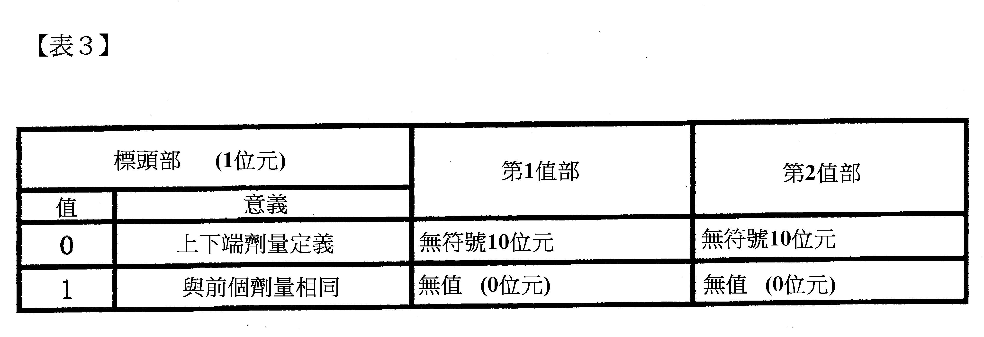
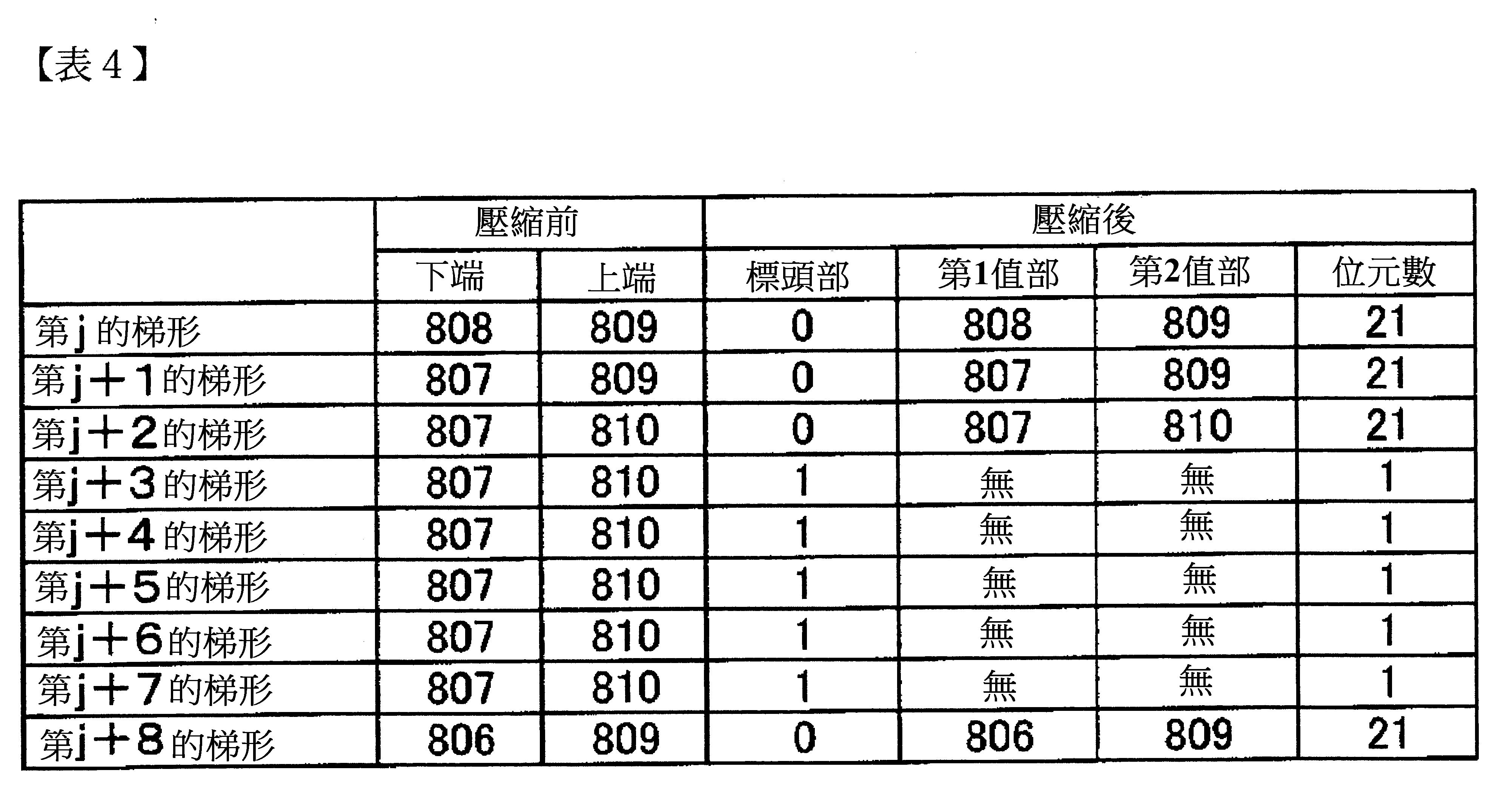
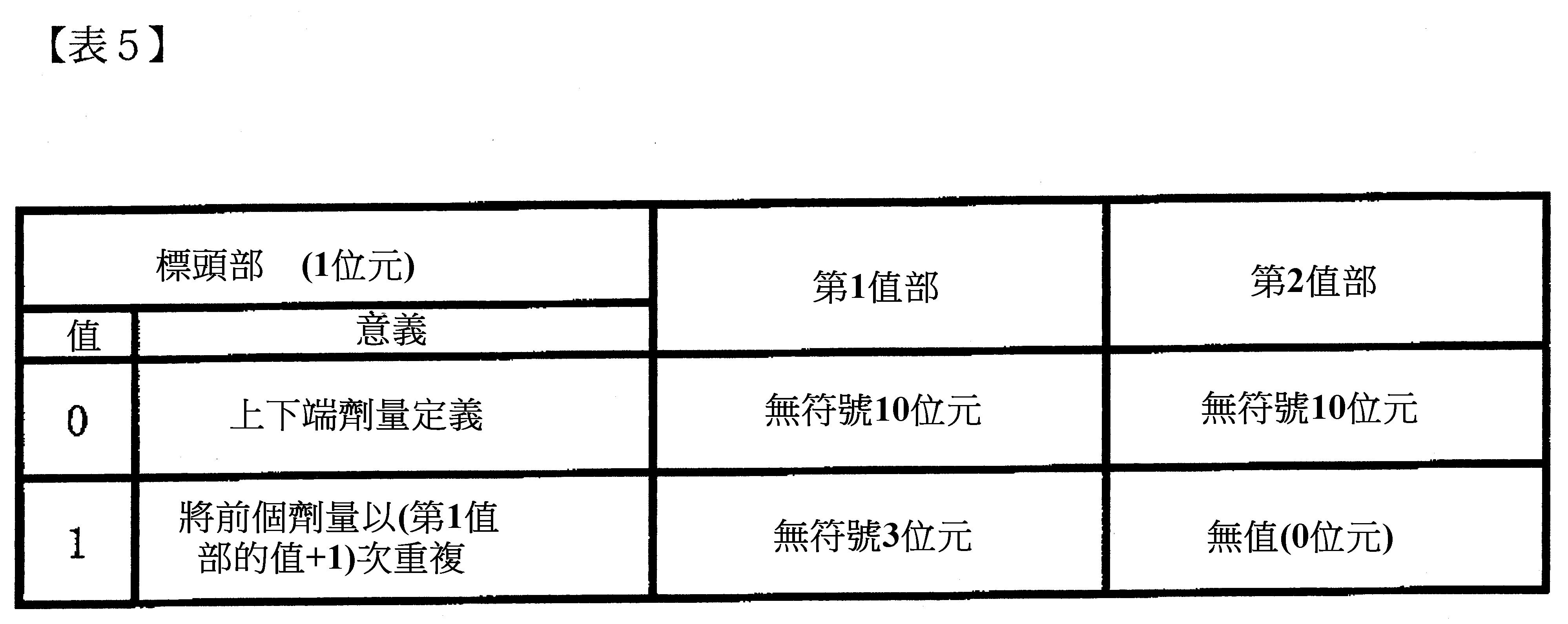
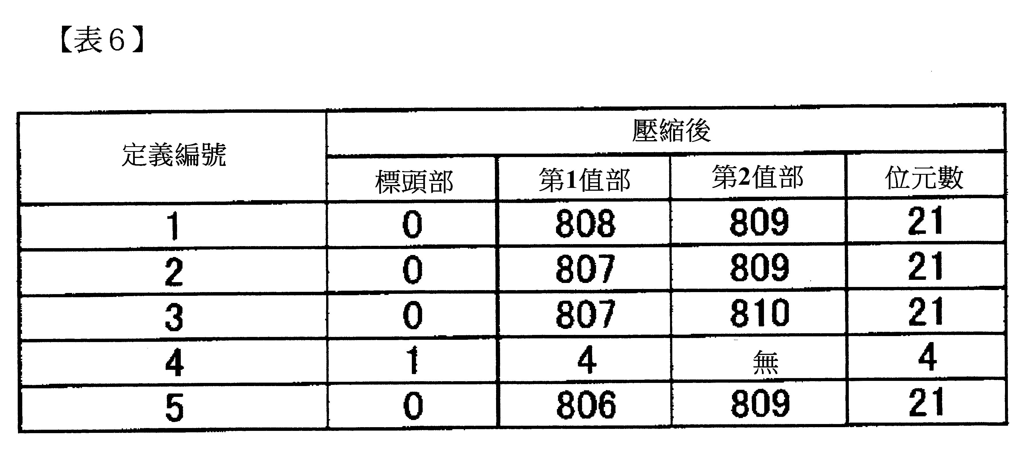
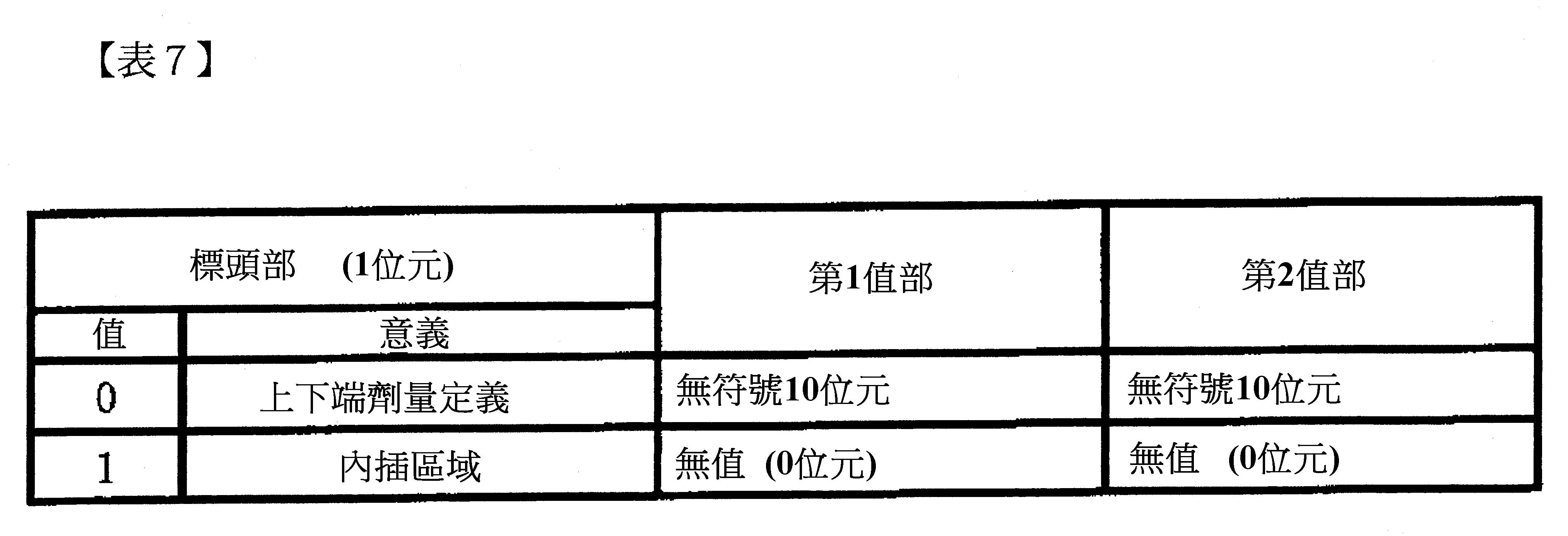
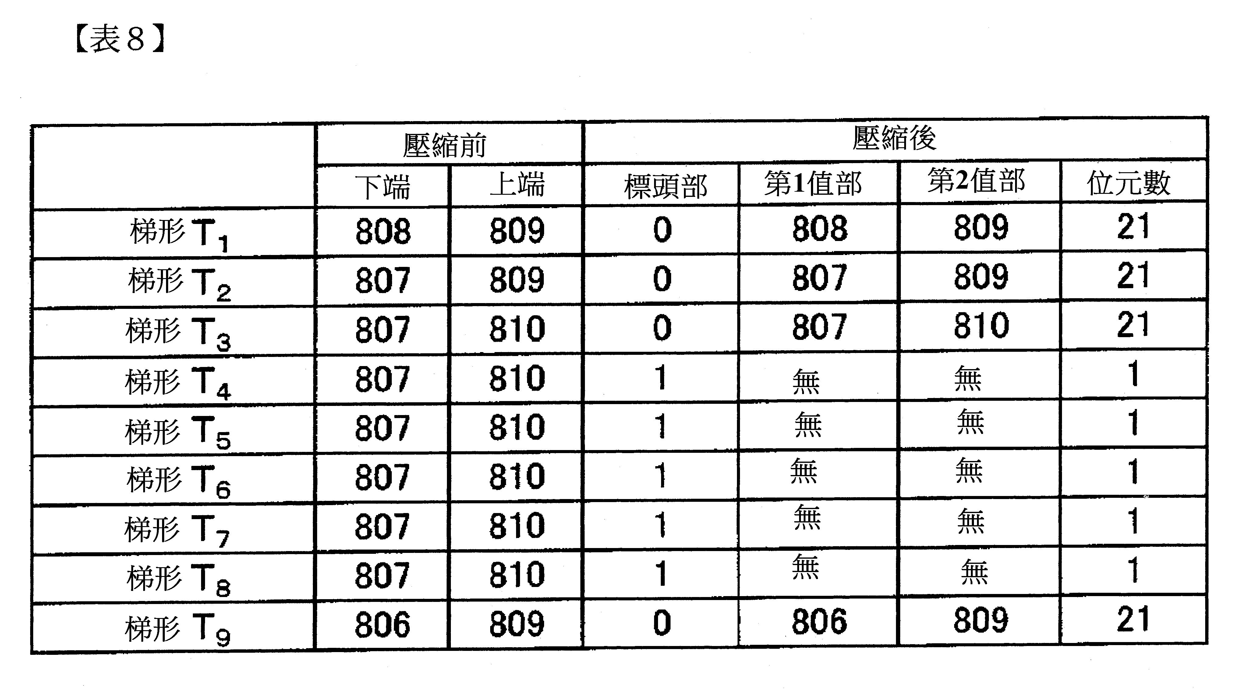
・・・之中,將第2以後的畫分的劑量資訊,變換成該畫分的劑量與前1個畫分的劑量之間的差分表現,因應差分值的大小改變差分表現的資料長。劑量資訊被變換成如以下表1所示的標頭部及值部構成的資料構造。在表1的例中,將壓縮前的劑量設為10位元。

Figure 02_image001
就某畫分的劑量而言,當與前1個畫分的劑量之間的差分比32灰階還大,且為128灰階以下時,將該劑量以:表示值部為差分表現1的2位元的標頭“01”、及表示與前1個畫分的劑量之間的差分之附符號8位元值部來表現。   就某畫分的劑量而言,當與前1個畫分的劑量之間的差分為32灰階以下時,將該劑量以:表示值部為差分表現2的2位元的標頭“10”、及表示與前1個畫分的劑量之間的差分之附符號6位元值部來表現。藉此,劑量資訊其資料大小被從10位元刪減至8位元(=2位元+6位元)。   當某畫分的劑量與前1個畫分的劑量相同時,將該劑量資訊僅以表示與前1個劑量相同之2位元的標頭“11”來表現。藉此,劑量資訊其資料大小被從10位元刪減成2位元。   就某畫分的劑量而言,當與前1個畫分的劑量之間的差分比128灰階還大時,將該劑量作為值部,附加表示值部為滿位元表現(無符號10位元)的2位元的標頭“00”。   劑量資訊的表現的變換(資料壓縮)的一例示於表2。在表2中為了方便說明,雖將壓縮前的劑量、及壓縮後的值部以10進位來表現,但實際為2進位表現。
Figure 02_image003
第j的畫分,壓縮前的劑量填入值部,被附加表示值部為滿位元表現(無符號10位元)的2位元的標頭“00”。   因為第j+1的畫分,與第j的畫分的劑量之間的差分比32灰階還大,且為128灰階以下,故標頭成為表示值部為差分表現1的“01”,在值部填入與第j的畫分的劑量之間的差分-33(附符號8位元)。   因為第j+2的畫分,與第j+1的畫分的劑量之間的差分為32灰階以下,故標頭成為表示值部為差分表現2的“10”,在值部填入與第j+1的畫分的劑量之間的差分-10(附符號6位元)。   因為第j+3的畫分,與第j+2的畫分的劑量之間的差分為32灰階以下,故標頭成為表示值部為差分表現2的“10”,在值部填入與第j+2的畫分的劑量之間的差分-5(附符號6位元)。   因為第j+4的畫分,與第j+3的畫分為相同劑量,僅以2位元的標頭“11”將表現變換。   在表2所示的例中,5個畫分的劑量資訊的壓縮前的資料大小為10位元×5=50位元。另一方面,壓縮後為12位元+10位元+8位元+8位元+2位元=40位元,確認到資料大小能被刪減。因此,對應與前1個畫分的劑量之間的差分的大小,藉由改變差分表現的資料長(在此例中為附符號8位元、附符號6位元、0位元),能將資料壓縮而表現劑量資訊。   與圖10、圖11比較,如圖12所示,藉由將劑量的定義順序設為鋸齒狀,劑量容易與前1個畫分變得相同,利用上述方法能有效率地將資料壓縮。例如,如圖13所示,因為劑量D3 - 1 的畫分鄰接於劑量D2 - 3 的畫分,劑量容易成為相同值,資料的壓縮效率佳。 [第2實施形態]   在上述第1實施形態中,將梯形分割成複數畫分,在各畫分定義1個劑量,在1個畫分內,在任何位置劑量都相同,但在描繪資料DT1中,定義在各畫分兩端的劑量,將兩端的劑量進行線性插值而求出在任意座標的劑量也可以。   例如,如圖15所示,將1個梯形T以網目大小分割成3個畫分SC1、SC2、SC3。接著,定義在畫分SC1的下端、畫分SC1的上端(畫分SC2的下端)、畫分SC2的上端(畫分SC3的下端)、畫分SC3的上端4個地方的劑量D1、D2、D3、D4。在描繪資料DT1中依序定義劑量D1、D2、D3、D4。   讀取描繪資料DT1的控制計算機52,能夠將畫分SC1內畫素pj的劑量Dj,以將畫分SC1兩端的劑量D1、D2進行線性插值而求出。又,畫分SC3內的畫素pk的劑量Dk,能夠將畫分SC3兩端的劑量D3、D4進行線性插值而求出。 [第3實施形態]   在上述第1實施形態中,將梯形分割成複數畫分,在各畫分定義1個劑量,但不分割成複數畫分,定義在梯形的兩端的劑量,將兩端的劑量進行線性插值而求出在任意座標的劑量也可以。   例如,如圖16所示,定義1個梯形T的下端與上端的2個地方的劑量D1、D2。在描繪資料DT1中依序定義劑量D1、D2。   讀取描繪資料DT1的控制計算機52,能夠將梯形T內的畫素pj的劑量Dj,以將梯形T兩端的劑量D1、D2進行線性插值而求出。   如圖17(a)所示,考慮到將梯形T1 、T2 、T3 、T4 的下端的劑量作為D1L 、D2L 、D3L 、D4L 、將上端的劑量作為D1U 、D2U 、D3U 、D4U 的情形。描繪資料DT1中的劑量的定義順序如圖17(b)所示,可以是依梯形T1 的下端、上端、梯形T2 的下端、上端、梯形T3 的下端、上端的順序、也可以是如圖17(c)所示,依梯形T1 的上端、下端、梯形T2 的上端、下端、梯形T3 的上端、下端的順序。又,如圖17(d)所示,以梯形T1 的下端、上端、梯形T2 的上端、下端、梯形T3 的下端、上端的鋸齒狀定義也可以。此外,圖17(b)~(d)僅表示描繪資料DT1之中,標頭PHd的部分。   變換裝置70將梯形的上端與下端的劑量資訊,變換成如以下表3所示的由標頭部、第1值部及第2值部所構成的資料構造,將資料壓縮也可以。在表3的例中,將壓縮前的劑量設為10位元。
Figure 02_image005
當某梯形的兩端(上下端)的劑量與前1個梯形的兩端的劑量相同時,將該梯形的劑量資訊僅以表示與前1個梯形的劑量相同之1位元的標頭“1”來表現。   當某梯形的兩端的劑量的至少一者與前1個梯形的兩端的劑量不同時,將下端的劑量填入第1值部、將上端的劑量填入第2值部,附加表示定義兩端的劑量的1位元的標頭“0”。   劑量資訊的表現的變換(資料壓縮)的一例示於表4。在表4中為了方便說明,雖將壓縮前的劑量、及壓縮後的值部以10進位來表現,但實際為2進位表現。
Figure 02_image007
第j~j+2的梯形定義兩端的劑量,附加標頭“0”。   因為第j+3~j+7的梯形,與兩端的劑量為第j+2的梯形的兩端的劑量相同,故僅以1位元的標頭“1”來表現。   第j+8的梯形定義兩端的劑量,附加標頭“0”。   第j~j+8的9個梯形的兩端的劑量資訊的壓縮前的資料大小為10位元×2×9=180位元。另一方面,壓縮後成為(1+10×2)×4+1×5=89位元,確認到資料大小能被刪減。   變換裝置70將梯形的上端與下端的劑量資訊,變換成如以下表5所示的由標頭部、第1值部及第2值部所構成的資料構造,將資料再壓縮也可以。
Figure 02_image009
當兩端(上下端)的劑量為相同梯形連續時,以表示與前個梯形的劑量相同的1位元的標頭“1”、以及劑量相同的梯形連續之數(無符號3位元)來表現劑量資訊。   當某梯形的兩端的劑量的至少一者與前1個梯形的兩端的劑量不同時,將下端的劑量填入第1值部、將上端的劑量填入第2值部,附加表示定義兩端的劑量的1位元的標頭“0”。   將表4所示的壓縮前的劑量資訊以表5所示的資料構造變換之例表示於表6。
Figure 02_image011
因為在對應標頭“1”的第1值部定義“4”,解釋成第j+2的劑量重複5次。在該例中,成為(1+10×2)×4+(1+3)=88位元,確認到資料大小能再被刪減。 [第4實施形態]   上述第3實施形態中,定義在梯形兩端的劑量,將兩端的劑量進行線性插值求出在任意座標的劑量,但控制計算機52也可以描出外接於複數連續的梯形群的矩形,計算外接矩形的4頂點的劑量,將外接矩形內的任意的座標的劑量以4頂點的劑量的雙線性插值(Bilinear interpolation)來算出。   變換裝置70將梯形的上端與下端的劑量資訊,變換成如以下表7所示的由標頭部、第1值部及第2值部所構成的資料構造。
Figure 02_image013
將劑量以雙線性插值來算出的梯形的劑量資訊僅以1位元的標頭“1”來表現。定義兩端(上下端)的劑量的梯形,在標頭部定義“0”,下端的劑量定義成第1值部、上端的劑量定義成第2值部。   例如,將圖18所示的梯形T1 ~T9 的劑量資訊以如以下表8的方式表現。在該例中,9個梯形T1 ~T9 的劑量資訊成為(1+10×2)×4+1×5=89位元,確認到資料大小能被刪減。
Figure 02_image015
讀取描繪資料DT1的控制計算機52,如圖18所示,描繪外接於梯形T3 ~T9 的矩形R,算出外接矩形R的4頂點C00 、C01 、C10 、C11 的劑量。頂點C00 、C01 的劑量d00 、d01 為梯形T3 的下端、上端的劑量。   頂點C10 、C11 的劑量d10 、d01 藉由從梯形T9 的下端、上端的劑量內插或外插來算出。   如圖19所示,將外接矩形R的圖中左右方向的長度設為w、將圖中上下方向的長度設為h、將頂點C00 的座標設為(X0 、Y0 )時,將座標(x、y)中的劑量d(x , y) 從以下的雙線性插值式求出。
Figure 02_image017
將表7表示的標頭“1”,作為意味著內插區域以「第1值部的值+1」次重複者,再將資料量刪減也可以。   變換裝置70可以以硬體來構成,也可以由軟體來構成。以軟體來構成時,可以將實現變換裝置70的至少一部的機能的程式儲存至CD-ROM等記錄媒體,使電腦來讀取並執行。記錄媒體不限於磁碟或光碟等可裝卸之物,硬碟裝置或記憶體等固定型的記錄媒體也可以。   然而,本發明並不限於上述的實施形態,可以在實施階段中,以不脫離此內容的範圍內,改變及具體化構成要素。此外,也可以將上述實施形態所揭示的複數構成要素做適當的組合,完成各種發明。例如:也可以將實施形態所示的全部構成要素做一些刪除。再來,也可將不同的實施形態中的構成要素做適當的組合。Hereinafter, embodiments of the present invention will be described based on the drawings. [First Embodiment] Fig. 1 is a schematic diagram of a multiple charged particle beam drawing apparatus for drawing using the drawing data of the first embodiment of the present invention. In the embodiment, as an example of a charged particle beam, a configuration using an electron beam will be described. However, the charged particle beam is not limited to the electron beam, and other charged particle beams such as ion beams may be used. The drawing device 1 shown in FIG. 1 includes a drawing unit 10 that irradiates an object such as a mask and a wafer with an electron beam to draw a desired pattern, and a control unit 50 that controls the drawing operation of the drawing unit 10. The drawing unit 10 has an electron beam lens barrel 12 and a drawing room 30. The electron beam barrel 12 is provided with an electron gun 14, an irradiation lens 16, an aperture member 18, a shielding plate 20, a reduction lens 22, a restricting aperture member 24, an objective lens 26, and a deflector 28. An XY stage 32 is arranged in the drawing room 30. A blank mask 34 as a drawing target substrate is placed on the XY stage 32. The drawing target substrate includes, for example, a wafer, and a reduction projection type exposure device or an extreme ultraviolet exposure device that uses an excimer laser as a light source to transfer the pattern to the wafer. Mask for exposure. In addition, the drawing target substrate includes a patterned mask. For example, because the Ravinson type mask requires two times of drawing, there are cases where the second pattern is drawn on an object that has been processed by the mask after one drawing. A mirror 36 for measuring the position of the XY stage 32 is further arranged on the XY stage 32. The control unit 50 has a control computer 52, deflection control circuits 54 and 56, and a stage position detector 58. The control computer 52, the deflection control circuits 54, 56, and the stage position detector 58 are connected to each other by a bus. The electron beam 40 emitted from the electron gun 14 irradiates the entire hole member 18 in a substantially vertical manner by the irradiation lens 16. In the hole member 18, holes (opening portions) are formed in a matrix with a predetermined arrangement pitch. The electron beam 40 illuminates, for example, an area including all holes of the hole member 18. By passing a part of the electron beam 40 through the plurality of holes, multiple beams 40a-40e as shown in FIG. 1 are formed. In the shielding plate 20, through holes are formed in accordance with the arrangement positions of the holes of the hole member 18, and a blocker formed by a pair of two electrodes is arranged in each through hole. The electron beams 40a-40e passing through the through holes are independently deflected by the voltage applied by the blocker. With the relevant bias for shadow control. Thereby, the plurality of blockers respectively perform shielding deflection of the corresponding beam among the multiple beams passing through the plurality of holes of the hole member 18. The multiple beams 40 a to 40 e that have passed through the shielding plate 20 are reduced by the reducing lens 22 and proceed toward the center hole formed in the restricting hole member 24. Here, the position of the electron beam deflected by the blocker of the shielding plate 20 is shifted from the center hole of the restricting hole member 24 and is shielded by the restricting hole member 24. On the other hand, the electron beam that is not deflected by the blocker of the shielding plate 20 passes through the center hole of the restricting hole member 24. Thereby, the restricting hole member 24 shields each beam deflected in a beam OFF state by the blocker of the shielding plate 20. Then, after the beam is turned ON until the beam is turned OFF, the beam passing through the restricting hole member 24 becomes a single shot beam. The multiple beams 40a-40e passing through the restricting hole member 24 are focused by the objective lens 26, and become a pattern image having a desired reduction ratio. The beams (the entire multiple beams) passing through the restricting hole member 24 are integrated in the same direction by the deflector 28 to be deflected, and are irradiated to each irradiation position on the blank mask 34 of each beam. When the XY stage 32 moves continuously, the beam irradiation position is controlled by the deflector 28 to follow the movement of the XY stage 32. The movement of the XY stage 32 is performed by a stage control unit not shown, and the position of the XY stage 32 is detected by the stage position detector 58. The multiple beams irradiated at one time are ideally arranged at a pitch obtained by multiplying the arrangement pitch of the plurality of holes of the hole member 18 by the aforementioned desired reduction ratio. This drawing device performs drawing operations in a line-by-line scanning method in which shooting beams are continuously and sequentially irradiated. When drawing a desired pattern, beams necessary for the pattern are controlled to be turned ON by masking control. The control computer 52 reads the drawing data DT1 from the memory device 60, and performs data conversion processing of plural pieces of the drawing data to generate shooting data specific to the device. In the shooting data, the irradiation amount and irradiation position coordinates of each shooting are defined. The control computer 52 outputs the irradiation amount of each shot to the deflection control circuit 54 based on the shot data. The deflection control circuit 54 divides the input irradiation amount by the current density to obtain the irradiation time t. Next, when the deflection control circuit 54 performs a corresponding shot, it applies a deflection voltage to the corresponding blocker of the shielding plate 20 so that the blocker becomes the beam ON only during the irradiation time t. In addition, the control computer 52 outputs the deflection position data to the deflection control circuit 56 so that each beam is deflected at the position (coordinate) indicated by the shooting data. The deflection control circuit 56 calculates the deflection vector and applies the deflection voltage to the deflector 28. In this way, the multiple beams shot this time were integrated and deflected. Next, a method of generating the drawing data DT1 will be described. First, the layout of the semiconductor integrated circuit is designed, and the layout data design data (CAD data) DT0 is generated. Next, the design data DT0 is converted by the conversion device 70 to generate the drawing data DT1 input to the control computer 52 of the drawing device 1. When a polygonal figure is included in the design data DT0, the conversion device 70 performs a division process of dividing the polygonal figure into a plurality of trapezoids. The plural trapezoids generated by this division process each have a pair of opposite sides parallel to the first direction (for example, the longitudinal direction). The plural trapezoids are arranged continuously along a second direction (for example, a horizontal direction) perpendicular to the first direction. Adjacent trapezoids share a side parallel to the first direction as a common side. For example, as shown in Fig. 2, the polygonal figure 100 is divided into plural trapezoids T 1 to T n by the dividing process. Here, n is an integer of 2 or more. The trapezoids T 1 to T n each have a pair of opposite sides parallel to the longitudinal direction (y direction), and are connected in the lateral direction (x direction). For example, the trapezoid T 2 having a set of parallel sides S 1 and S 2, S 1 side becomes T 1 as a common trapezoidal edge S 2 side of the trapezoidal become common edge 3 T. In addition, the sides S 0 and S n of the trapezoids T 1 and T n at both ends in the connection direction do not become common sides. According to the shape of the polygonal figure, perform the steps shown in Figure 3 (a), (b), Figure 4 (a) ~ (d), Figure 5 (a), (b), Figure 6 (a), (b) Various segmentation processing. In FIG. 3(a), as in FIG. 2, each trapezoid has a pair of opposite sides parallel to the vertical direction, and is subjected to a division process such as connecting in the horizontal direction. In FIG. 3(b), each trapezoid has a pair of opposite sides parallel in the horizontal direction, and is subjected to a division process such as connecting in the vertical direction. In Fig. 4(a), the polygonal pattern has sides S 0 and S 4 extending in parallel in the vertical direction, and a side S x1 that connects the lower ends of the sides S 0 and S 4 to each other and extends in the horizontal direction. The plural trapezoids generated by the dividing process each have a pair of opposite sides parallel in the vertical direction, and while connecting in the horizontal direction, the lower side is connected linearly in the horizontal direction. In FIG. 4(b), the polygonal pattern has sides S 0 and S 4 extending in parallel in the vertical direction, and a side S x2 that connects the upper ends of the sides S 0 and S 4 to each other and extends in the horizontal direction. The plural trapezoids generated by the dividing process each have a pair of opposite sides parallel in the vertical direction, and while connecting in the horizontal direction, the upper side is connected in a straight line in the horizontal direction. In FIG. 4 (c), having a polygonal pattern extending along a direction parallel to the lateral sides of S 0, S 4, and the right side S 0, S 4 S connecting each other edge extending along the longitudinal direction Y1. The plurality of pedestal shapes generated by the division processing each have a pair of opposite sides parallel in the horizontal direction, which are connected in the vertical direction while the right side is linearly connected in the vertical direction. In FIG. 4 (d), having a polygonal pattern extending along a direction parallel to the lateral sides of S 0, S 4, and the left side S 0, S 4 connecting one another along edges extending in the longitudinal direction S y2. The plural trapezoids generated by the division process each have a pair of opposite sides parallel in the horizontal direction, which are connected in the vertical direction while the left side is linearly connected in the vertical direction. Fig. 5 (a) and (b) show division processing when a polygonal figure is composed of only sides parallel to the vertical direction or the horizontal direction. At this time, the polygonal figure is divided into plural rectangles (rectangles). Fig. 5(a) shows an example in which the divided rectangles are connected in the horizontal direction, and Fig. 5(b) shows an example in which the divided rectangles are connected in the vertical direction. 6(a) and (b) show division processing when a polygonal figure is composed of only sides parallel to the vertical direction or the horizontal direction, and sides that are 45° from the vertical direction (lateral direction). Fig. 6(a) shows an example in which the divided trapezoids are connected in the horizontal direction, and Fig. 6(b) shows an example in which the divided trapezoids are connected in the vertical direction. The conversion device 70 divides the polygonal figure into a plurality of trapezoids, and expresses the vertex positions of the trapezoids in displacements calculated from the vertex positions of the adjacent trapezoids to generate drawing data DT1. For example, in the example shown in FIG. 2, the coordinates (x0, y0) of the vertex P 01 at the lower end of the side S 0 are defined as the origin of the polygonal figure. Next, the position of the vertex P 02 at the upper end of the side S 0 is defined by the origin P 01 of the figure arrangement position and the length L 0 of the side S 0 extending vertically from this point. Position to the side S 0 parallel to the side S 0 abutment edge S lower vertices 1 P. 11, the Department of highly trapezoid T 1 as (side S 0 and the side S spaced 1) L 1, and from the apex P adjacent The longitudinal displacement δ 11 from 01 is defined. Further, the upper end edge S 1 vertex position P 12, based trapezoidal height T 1 L 1, from the displacement δ and the adjacent vertex P 02 12 starting in the vertical direction is defined. To the side S 1 parallel and to the side S 1 adjacent to the side of the S position lower vertex P 2 21, based trapezoidal T height L 2 2 a and δ displacement from the vertical direction 11 starting adjacent vertex P 21 to definition. In addition, the position of the upper end vertex P 22 of the side S 2 is defined by the height L 2 of the trapezoid T 2 and the displacement δ 22 in the longitudinal direction from the adjacent vertex P 12 . In other words, the positions of the common vertices P 21 and P 22 of the trapezoid T 2 and the trapezoid T 3 are calculated from the positions of the common vertices P 11 and P 12 of the trapezoid T 1 and the trapezoid T 2 in the longitudinal direction displacement δ 21 , δ 22 and the displacement L 2 in the lateral direction are defined. Hereinafter, similarly, to the side and parallel to S m 1 P m1 vertex position adjacent to the lower end of a side edge S m and S m ー, based trapezoid T m of a height (S m1 and the side edges of the S m The interval) L m and the displacement δ m1 in the longitudinal direction from the adjacent vertex P (m - 1)1 are defined. In addition, the position of the upper end vertex P m2 of the side S m is defined by the height L m of the trapezoid T m and the displacement δ2 m2 in the longitudinal direction from the adjacent vertex P (m - 1)2 . Here, m is an integer of 2 to n or more. Thus, the corresponding trapezoidal polygonal pattern group can be coupled by: P 01 pattern layout position coordinate origin (x0, y0), the length L 0 0 S side of each trapezoid T 1 ~ T n height L 1 ~ L n . Displacements δ 11 , δ 12 to δ n1 , and δ n2 in the direction perpendicular to the connecting direction of the trapezoid from the adjacent vertices define the shape. In addition, the displacements δ 11 , δ 12 to δ n1 , and δ n2 are values with signs. The heights L 1 to L n of the trapezoids T 1 to T n can be regarded as the displacement in the connecting direction of the trapezoids from the adjacent vertices. FIG. 7 shows an example of the data structure of the drawing data DT1 defining the connected trapezoid group. The drawing data DT1 has: a header PH, a header PHd, and shape information EP. The header PH defines a graphic code (Code), a flag (flag), and the number of graphic elements (N). The figure code is the information indicating that the polygonal figure is divided into the trapezoid group. For example, in Figure 3 (a), (b), Figure 4 (a) ~ (d), Figure 5 (a), (b) ), Figure 6 (a), (b) shows the corresponding segmentation processing. The mark in the header PH includes information necessary for the recognition of the graphic representation, such as the byte length of the data included in the shape information EP described later. The number of figure elements (N) represents the number of connected trapezoid groups (polygon figures) with the same figure code. Because the shape information EP is created for each connected trapezoid group, when the number of graphic elements (N) is 2 or more, the plural shape information is created. The header PHd contains the doses AI 1 ˜AI n of the trapezoid T 1 ˜T n . The flag flag of the header PHd indicates the byte length of the data of the doses AI 1 to AI n . The number N of elements in the header PHd represents the number of trapezoids defining the dose. EP in the shape information comprising: information to define the shape of the trapezoidal connecting group, e.g., graphical configuration coordinate position of the origin (x0, y0), the edge length L 0 0 S, the height of each trapezoid T ~ 1 T n is L 1 to L n , the displacements δ 11 , δ 12 to δ n1 , and δ n2 in the direction perpendicular to the connecting direction of the trapezoid from the adjacent vertices. In addition, the shape information EP includes the connection number Nconnect of the trapezoid. For example, the drawing data DT1 representing the connected trapezoid groups shown in FIGS. 3(a) and (b) has a data structure as shown in FIG. 3(c). In addition, the header PHd is omitted in the data structure shown in FIG. 3(c). In the figure code, the connecting direction of the trapezoid is defined in a distinguishable manner, and the vertex is used as the origin of the figure arrangement position, etc. The number of connections Nconnect is 4. The drawing data DT1 representing the connected trapezoid groups shown in FIGS. 4(a) to (d) has a data structure as shown in FIG. 4(e). In addition, the header PHd is omitted in the data structure shown in FIG. 4(e). In the figure code, the connecting direction of the trapezoid is defined in a distinguishable manner, the side of the plural trapezoid is connected in a straight line, and the vertex is used as the origin of the figure arrangement position. The number of connections Nconnect is 4. In FIGS. 4(a) to (d), one side of the connected trapezoids is connected in a straight line, and as for the vertex of the side, there is no displacement in the direction perpendicular to the connecting direction of the trapezoid between adjacent vertices. Therefore, when the number of connections Nconnect is the same, the data amount of the shape information EP becomes smaller than that of Figs. 3(a) and (b). The drawing data DT1 representing the connected trapezoid groups shown in FIGS. 5(a) and (b) has a data structure as shown in FIG. 5(c). In addition, the header PHd is omitted in the data structure shown in FIG. 5(c). In the figure code, the connection direction of the plural rectangles and rectangles divided into the plural rectangles and the connection direction of the rectangles, and which vertex is used as the origin of the figure arrangement position are defined in a distinguishable manner. The drawing data DT1 representing the connected trapezoid groups shown in FIGS. 6(a) and (b) has a data structure as shown in FIG. 6(c). In addition, the header PHd is omitted in the data structure shown in FIG. 6(c). The shape information EP defines a direction flag (flag) as shown in FIG. 6(d). This is because when the polygonal figure is composed of only the sides parallel to the vertical or horizontal direction, and the sides at 45° from the vertical direction (horizontal direction), each side can be marked in the direction of Figure 6(d) Any kind of expression. In the figure code, the connecting direction of the trapezoid is defined in a distinguishable manner, and the vertex is used as the origin of the figure arrangement position, etc. In addition, FIG. 6(c) is drawing data DT1 showing the connected trapezoid group of FIG. 6(a). In electron beam drawing, as a phenomenon that causes pattern size variation, it is known that there is a proximity effect unique to an extremely short EUV mask with an influence radius of about 300 nm to 400 nm. In the calculation of the amount of exposure correction that takes this effect into consideration, the drawing area is divided into meshes of, for example, about 30 nm, and the calculation is performed for each divided small area. In the present embodiment, as shown in FIG. 8, when the trapezoid divided into the polygonal figure is larger than the mesh size MS, one trapezoid is divided into plural divisions by the mesh size MS, and the dose is defined for each division. For example, as shown in FIG. 9, a trapezoid whose length in the longitudinal direction (a direction perpendicular to the connecting direction of the trapezoids) is larger than the mesh size is divided into plural divisions by the mesh size MS. 1 trapezoid, including at least 1 mesh size MS, and a small mesh smaller than the mesh size MS. When the size of the trapezoid is an integer multiple of the mesh size MS, no small points are generated. In the example shown in FIG. 9, one trapezoid T is divided into three divisions SC1, SC2, and SC3. The size of the pixels SC1 and SC2 in the longitudinal direction becomes the mesh size MS. The picture point SC3 is a small picture point smaller than the mesh size MS. Define the dose in the painting points SC1, SC2 and SC3 respectively. As a method of dividing the trapezoid into plural divisions and defining the dose in each division, there are, for example, those shown in FIGS. 10 to 12. Figure 10 (a), Figure 11 (a), Figure 12 (a) shows an example of dividing the trapezoid into a plural number of points, Figure 10 (b), Figure 11 (b), Figure 12 (b) will be in each drawing The order of the defined doses is indicated by arrows. In these examples, the connecting direction of the trapezoids is the left-right direction in the figure, and the longitudinal direction of each trapezoid is the up-down direction in the figure. In Fig. 10(a)(b), each trapezoid is divided into plural points by the mesh size from the lower end side, and the dose is sequentially defined in the upward direction from the lower part. In Fig. 11(a)(b), each trapezoid is divided into plural points by the mesh size from the upper end side, and the dose is sequentially defined in the downward direction from the upper part. In FIG. 12(a), the trapezoid divided into plural divisions by the mesh size from the lower end side and the trapezoid divided into the plural divisions by the mesh size from the upper end side are alternately arranged. As shown in FIG. 12(b), in the trapezoid divided into plural points by the mesh size from the lower end side, the doses are sequentially defined in the upward direction from the lower part. In a trapezoid that is divided into plural points by the mesh size from the upper end side, the dose is sequentially defined in the downward direction from the upper part. The order of definition of the dose becomes zigzag. Using the method shown in Fig. 12(a)(b), the trapezoid is divided into plural divisions, and an example of defining the dose in each division is shown in Fig. 13. The odd-numbered trapezoids T 1 , T 3 ... are divided into plural points by the mesh size from the bottom side. The even-numbered trapezoids T 2 , T 4 ... are divided into plural points by the mesh size from the top side. In the ladder T 1, sequentially from the dosage Videos defined start points upward direction lower side D 1 - 1, D 1 - 2. In the ladder T 2, drawn from the downward direction side of the partial sequence begins defined dose D 2 - 1, D 2 - 2, D 2 - 3. Trapezoidal T 3, the points are sequentially defined Videos dose from the start of the upward direction of the lower side of D 3 - 1, D 3 - 2, D 3 - 3, D 3 - 4. Trapezoidal T 4, drawn from the upper side partial sequence beginning in the downward direction is defined dose D 4 - 1, D 4 - 2, D 4 - 3, D 4 - 4. FIG. 14 shows an example of the data structure of the drawing data DT1 when each trapezoid is divided into a plurality of divisions by the mesh size, and the dose is defined in each division. PHd header comprising: a mesh size MS, a plurality of points each draw trapezoid dose D 1 - 1, D 1 - 2, D 2 - 1, D 2 - 2 · · ·. When the entire mesh size MS of the mask is a fixed value, the mesh size MS may not be defined in the header PHd. In this way, according to this embodiment, a polygonal figure is regarded as a group of trapezoids in which a plurality of parallel trapezoids are connected in one direction, and expressed only by the coordinates of the origin of the figure arrangement position. The vertex positions of other trapezoids are calculated from the adjacent vertex It is expressed by displacement, and drawing data DT1 is generated. Therefore, compared with the case where each trapezoid is expressed by the coordinates of the origin of the arrangement position and the displacement from the coordinates to the other three vertices, the amount of drawing data can be reduced. In addition, each trapezoid is divided into plural divisions with small sizes (mesh size), and drawing data DT1 with a defined dose in each division is generated. Therefore, it can be used as a correction calculation to suppress the pattern size variation caused by the phenomenon of the small influence radius. In the above embodiment, the rendering of the data DT1 header PHd defined dose Videos complex partial information D 1 - 1, D 1 - 2, D 2 - 1, D 2 - 2 · · · administering data compression processing , To cut down the data volume of dose information. For example, the complex is defined in the header information PHd painting divided doses D 1 - 1, D 1 - 2, D 2 - 1, D 2 - 2 · · · in the second and subsequent painting divided dose information, Converted to the difference between the dose of the pixel and the dose of the previous one, the data length of the difference is changed according to the difference value. The dose information is converted into a data structure composed of a header and a value as shown in Table 1 below. In the example in Table 1, the dose before compression is set to 10 bits.
Figure 02_image001
Regarding the dose of a certain pixel, when the difference with the dose of the previous one pixel is larger than 32 gray scales and less than 128 gray scales, the dose is expressed as the value of the differential expression 1. It is expressed by a 2-bit header "01" and a signed 8-bit value part indicating the difference between the dose and the previous one minute. Regarding the dose of a certain picture minute, when the difference with the dose of the previous picture minute is 32 gray scales or less, the dose is expressed as the 2-bit header "10 with the value part of the difference expression 2"", and a 6-bit value part with a sign indicating the difference between the dose and the previous one minute. In this way, the data size of the dose information is reduced from 10 bits to 8 bits (= 2 bits + 6 bits). When the dose of a certain picture minute is the same as the dose of the previous picture minute, the dose information is only represented by the header "11" which represents the same 2-bit as the previous one. As a result, the data size of the dose information is reduced from 10 bits to 2 bits. Regarding the dose of a certain division, when the difference between the dose of the previous division and the dose of the previous division is greater than 128 gray scales, the dose is regarded as the value part, and the additional indication value part is the full bit expression (unsigned 10 Bit) the 2-bit header "00". An example of the transformation (data compression) of the expression of dose information is shown in Table 2. In Table 2, for convenience of explanation, although the dose before compression and the value after compression are expressed in decimal, they are actually expressed in binary.
Figure 02_image003
For the j-th pixel, the dose before compression is filled in the value part, and a 2-bit header "00" indicating that the value part is full-bit representation (unsigned 10 bits) is added. Since the difference between the dose of the j+1th pixel and the jth pixel is larger than 32 gray scales and less than 128 gray scales, the header becomes "01" indicating that the value part is the difference expression 1. The value part is filled in with the difference -33 (8 bits with sign) from the dose of the j-th division. Because the difference between the dose of the j+2th image point and the j+1th image point is 32 gray scales or less, the header becomes "10" indicating that the value part is the difference expression 2, and the value part is filled with The difference between the doses of j+1 points is -10 (6 bits with sign). Since the difference between the dose of the j+3th image point and the j+2th image point is 32 gray scales or less, the header becomes "10" indicating that the value part is the difference expression 2, and the value part is filled with The difference between the doses of j+2 points is -5 (6 bits with sign). Because the j+4th picture points have the same dose as the j+3th picture points, only the 2-bit header "11" will change the expression. In the example shown in Table 2, the data size of the dose information of 5 divisions before compression is 10 bits×5=50 bits. On the other hand, it is 12 bits + 10 bits + 8 bits + 8 bits + 2 bits = 40 bits after compression, and it is confirmed that the data size can be reduced. Therefore, corresponding to the magnitude of the difference between the dose and the previous one minute, by changing the data length of the difference (in this example, 8-bit with sign, 6-bit with sign, and 0-bit). Compress the data to express dose information. Compared with Fig. 10 and Fig. 11, as shown in Fig. 12, by setting the dose definition order to be zigzag, the dose is easily the same as the previous one, and the data can be compressed efficiently by the above method. For example, as shown in FIG 13, since the dose D 3 - 1 Videos adjacent divided dose D 2 - Videos 3 points, the dosage tends to be the same value, the data compression efficiency is good. [Second Embodiment] In the above-mentioned first embodiment, the trapezoid is divided into plural divisions, and one dose is defined in each division. Within one division, the dose is the same at any position, but in the drawing data DT1 , Define the dose at both ends of each division, and linearly interpolate the dose at both ends to obtain the dose at any coordinate. For example, as shown in FIG. 15, one trapezoid T is divided into three points SC1, SC2, and SC3 by the mesh size. Next, define the doses D1, D2, 4 places at the lower end of the division SC1, the upper end of the division SC1 (the lower end of the division SC2), the upper end of the division SC2 (the lower end of the division SC3), and the upper end of the division SC3. D3, D4. The doses D1, D2, D3, and D4 are sequentially defined in the drawing data DT1. The control computer 52 that reads the drawing data DT1 can calculate the dose Dj of the pixel pj in the segment SC1 by linearly interpolating the doses D1 and D2 at both ends of the segment SC1. In addition, the dose Dk of the pixel pk in the division SC3 can be obtained by linearly interpolating the doses D3 and D4 at both ends of the division SC3. [Third Embodiment] In the above-mentioned first embodiment, the trapezoid is divided into plural points, and one dose is defined for each point. However, the doses at both ends of the trapezoid are defined without dividing into plural points. The dose may be linearly interpolated to obtain the dose at any coordinate. For example, as shown in FIG. 16, the doses D1 and D2 at two places at the lower end and the upper end of one trapezoid T are defined. The doses D1 and D2 are sequentially defined in the drawing data DT1. The control computer 52 reading the drawing data DT1 can obtain the dose Dj of the pixel pj in the trapezoid T by linearly interpolating the doses D1 and D2 at both ends of the trapezoid T. As shown in Figure 17(a), considering the doses at the lower ends of the trapezoids T 1 , T 2 , T 3 , and T 4 as D 1L , D 2L , D 3L , D 4L , and the upper doses as D 1U , D In the case of 2U , D 3U , D 4U . (B), may be lower by T 1 as a trapezoid, the upper end, a lower end of the trapezoid T 2, an upper end, a lower end of the trapezoid T 3, the upper end 17 of the sequence depicted in dose data DT1 defined sequence is shown, but may be FIG. 17 (c), by the upper end of the trapezoid T 1, the lower end, the upper end of trapezoid T 2, the lower end, the upper end of the trapezoid T. 3, the lower end of the sequence shown in FIG. And, FIG. 17 (d), the lower end of the trapezoid T 1, ie, the upper end of zigzag defined, T 2 trapezoidal upper and lower ends, the lower end of the ladder T 3, the upper end may be. In addition, FIGS. 17(b) to (d) only show the part of the header PHd in the drawing data DT1. The conversion device 70 converts the dose information at the upper and lower ends of the trapezoid into a data structure consisting of a header, a first value, and a second value as shown in Table 3 below, and the data may be compressed. In the example in Table 3, the dose before compression is set to 10 bits.
Figure 02_image005
When the dose at both ends (upper and lower ends) of a certain trapezoid is the same as the dose at both ends of the previous trapezoid, the dose information of the trapezoid shall only be indicated by the 1-bit header “1” which is the same as the dose of the previous trapezoid. "To show. When at least one of the doses at both ends of a trapezoid is different from the dose at both ends of the previous trapezoid, the dose at the lower end is filled in the first value part, and the dose at the upper end is filled in the second value part, and additional means that define both ends The 1-bit header "0" of the dose. An example of the transformation (data compression) of the expression of the dose information is shown in Table 4. In Table 4, for convenience of description, although the dose before compression and the value after compression are expressed in decimal, they are actually expressed in binary.
Figure 02_image007
The trapezoid of j~j+2 defines the dose at both ends, and the header "0" is added. Since the j+3 to j+7th trapezoid has the same dose at both ends of the j+2 trapezoid, it is only represented by a 1-bit header "1". The j+8th trapezoid defines the dose at both ends, and the header "0" is appended. The data size of the dose information at both ends of the nine trapezoids j to j+8 before compression is 10 bits×2×9=180 bits. On the other hand, after compression, it becomes (1+10×2)×4+1×5=89 bits, and it is confirmed that the data size can be reduced. The conversion device 70 converts the dose information at the upper and lower ends of the trapezoid into a data structure composed of a header, a first value, and a second value as shown in Table 5 below, and the data may be recompressed.
Figure 02_image009
When the doses at both ends (upper and lower ends) are continuous in the same trapezoid, the 1-bit header "1" which is the same as the dose of the previous trapezoid, and the number of continuous trapezoids with the same dose (unsigned 3 bits) To show dose information. When at least one of the doses at both ends of a trapezoid is different from the dose at both ends of the previous trapezoid, the dose at the lower end is filled in the first value part, and the dose at the upper end is filled in the second value part, and additional means that define both ends The 1-bit header "0" of the dose. The dose information before compression shown in Table 4 is shown in Table 6 as an example of the data structure conversion shown in Table 5.
Figure 02_image011
Because "4" is defined in the first value part of the corresponding header "1", it is interpreted as the j+2th dose repeated 5 times. In this example, it becomes (1+10×2)×4+(1+3)=88 bits, and it is confirmed that the data size can be further reduced. [Fourth embodiment] In the above-mentioned third embodiment, the dose at both ends of the trapezoid is defined, and the dose at both ends is linearly interpolated to obtain the dose at any coordinate. However, the control computer 52 can also trace the dose circumscribed by a plurality of continuous trapezoid groups. For a rectangle, the dose at the 4 vertices of the circumscribed rectangle is calculated, and the dose at any coordinate within the circumscribed rectangle is calculated by bilinear interpolation of the dose at the 4 vertices. The conversion device 70 converts the dose information at the upper and lower ends of the trapezoid into a data structure composed of a header, a first value, and a second value as shown in Table 7 below.
Figure 02_image013
The trapezoidal dose information calculated by bilinear interpolation of the dose is only represented by a 1-bit header "1". A trapezoid that defines the dose at both ends (upper and lower ends) is defined as "0" at the header, the dose at the lower end is defined as the first value part, and the dose at the upper end is defined as the second value part. For example, the dose information of the trapezoids T 1 to T 9 shown in FIG. 18 is expressed as shown in Table 8 below. In this example, the dose information of the nine trapezoids T 1 to T 9 becomes (1 + 10 × 2) × 4 + 1 × 5 = 89 bits, and it is confirmed that the data size can be deleted.
Figure 02_image015
The control computer 52 that reads the drawing data DT1 draws a rectangle R circumscribing the trapezoids T 3 to T 9 as shown in FIG. 18, and calculates the doses of the four vertices C 00 , C 01 , C 10 , and C 11 of the circumscribed rectangle R. The doses d 00 and d 01 at the vertices C 00 and C 01 are the doses at the lower and upper ends of the trapezoid T 3 . The doses d 10 and d 01 at the vertices C 10 and C 11 are calculated by interpolation or extrapolation from the dose at the lower and upper ends of the trapezoid T 9 . As shown in Figure 19, when the length of the circumscribed rectangle R in the left and right directions in the figure is set to w, the length in the vertical direction in the figure is set to h, and the coordinates of the vertex C 00 are set to (X 0 , Y 0 ), the coordinates (x, y) in a dose of d (x, y) is obtained from the following formula bilinear interpolation.
Figure 02_image017
The header "1" shown in Table 7 is regarded as meaning that the interpolation area is repeated with "the value of the first value part + 1" times, and the amount of data may be deleted. The conversion device 70 may be configured by hardware, or may be configured by software. When it is configured by software, a program that realizes at least one function of the conversion device 70 can be stored in a recording medium such as a CD-ROM, and the computer can read and execute it. The recording medium is not limited to removable objects such as magnetic disks or optical discs, and fixed recording media such as hard disk devices or memory may also be used. However, the present invention is not limited to the above-mentioned embodiment, and the constituent elements may be changed and embodied in the implementation stage without departing from the scope of the content. In addition, it is also possible to appropriately combine plural constituent elements disclosed in the above-mentioned embodiments to complete various inventions. For example, all the constituent elements shown in the embodiment may be deleted. Furthermore, the constituent elements in different embodiments may be appropriately combined.

10‧‧‧描繪部50‧‧‧控制部12‧‧‧電子束鏡筒30‧‧‧描繪室14‧‧‧電子槍16‧‧‧照射透鏡18‧‧‧孔構件20‧‧‧遮蔽板22‧‧‧縮小透鏡24‧‧‧限制孔構件26‧‧‧對物透鏡28‧‧‧偏向器32‧‧‧XY載台34‧‧‧空白遮罩36‧‧‧反射鏡52‧‧‧控制計算機54、56‧‧‧偏向控制電路58‧‧‧載台位置檢出器40‧‧‧電子束10‧‧‧Drawing part 50‧‧‧Control part 12‧‧‧Electron beam tube 30‧‧‧Drawing room 14‧‧‧Electron gun 16‧‧‧Illuminating lens 18‧‧‧Aperture member 20‧‧‧Shielding plate 22 ‧‧‧Reducing lens 24‧‧‧Limiting hole member 26‧‧‧Object lens 28‧‧‧Deflection device 32‧‧‧XY stage 34‧‧‧Blank mask 36‧‧‧Reflecting mirror 52‧‧‧Control Computer 54, 56‧‧‧Deflection control circuit 58‧‧‧ Stage position detector 40‧‧‧Electron beam

圖1為本發明的第1實施形態的多重帶電粒子束描繪裝置的概略圖。   圖2為表示多角形圖形的分割處理之例的圖。   圖3(a)及(b)為表示多角形圖形的分割處理之例的圖、(c)為表示描繪資料的資料構造之例的圖。   圖4(a)~(d)為表示多角形圖形的分割處理之例的圖、(e)為表示描繪資料的資料構造之例的圖。   圖5(a)及(b)為表示多角形圖形的分割處理之例的圖、(c)為表示描繪資料的資料構造之例的圖。   圖6(a)及(b)為表示多角形圖形的分割處理之例的圖、(c)為表示描繪資料的資料構造之例的圖、(d)為說明方向標記的圖。   圖7為表示描繪資料的資料構造之例的圖。   圖8為表示多角形圖形的分割處理之例的圖。   圖9為表示將梯形分割成複數畫分之例的圖。   圖10(a)為表示梯形的分割處理之例的圖、圖10(b)為表示劑量的定義順序的圖。   圖11(a)為表示梯形的分割處理之例的圖、圖11(b)為表示劑量的定義順序的圖。   圖12(a)為表示梯形的分割處理之例的圖、圖12(b)為表示劑量的定義順序的圖。   圖13為表示在各畫分定義的劑量的圖。   圖14為表示描繪資料的資料構造之例的圖。   圖15為表示第2實施形態的劑量的定義方法的圖。   圖16為表示第3實施形態的劑量的定義方法的圖。   圖17(a)為表示在梯形的上下端定義劑量的圖、圖17(b)~(d)為表示描繪資料的資料構造之例的圖。   圖18為表示外接於複數梯形的矩形之例的圖。   圖19為說明用雙線性插值來算出劑量的圖。Fig. 1 is a schematic diagram of a multiple charged particle beam drawing apparatus according to a first embodiment of the present invention.   FIG. 2 is a diagram showing an example of the division processing of a polygonal figure.   Figures 3 (a) and (b) are diagrams showing examples of polygonal figure division processing, and (c) is a diagram showing examples of data structure of drawing data.   Figures 4 (a) to (d) are diagrams showing examples of polygonal figure division processing, and (e) are diagrams showing examples of data structure of drawing data.   Figures 5 (a) and (b) are diagrams showing examples of polygonal figure division processing, and (c) is a diagram showing examples of data structure of drawing data.   Figures 6 (a) and (b) are diagrams showing examples of the division processing of a polygonal figure, (c) is a diagram showing an example of the data structure of the drawing data, and (d) is a diagram explaining direction marks.   FIG. 7 is a diagram showing an example of the data structure of the drawing data.   FIG. 8 is a diagram showing an example of the division processing of a polygonal figure.   FIG. 9 is a diagram showing an example of dividing a trapezoid into a plurality of divisions.   Fig. 10(a) is a diagram showing an example of trapezoidal division processing, and Fig. 10(b) is a diagram showing the definition order of dose.   Fig. 11(a) is a diagram showing an example of a trapezoidal division process, and Fig. 11(b) is a diagram showing the order of defining the dose.   Fig. 12(a) is a diagram showing an example of trapezoidal division processing, and Fig. 12(b) is a diagram showing the order of definition of dose.   Fig. 13 is a graph showing the dose defined in each division.   FIG. 14 is a diagram showing an example of the data structure of the drawing data.   Fig. 15 is a diagram showing a method of defining a dose in the second embodiment.   Fig. 16 is a diagram showing a method of defining a dose in the third embodiment.   Fig. 17(a) is a diagram showing the doses defined at the upper and lower ends of the trapezoid, and Figs. 17(b) to (d) are diagrams showing examples of the data structure of the drawing data.   FIG. 18 is a diagram showing an example of a rectangle circumscribing a plurality of trapezoids.   Figure 19 is a diagram illustrating the use of bilinear interpolation to calculate the dose.

1‧‧‧描繪裝置 1‧‧‧Drawing device

10‧‧‧描繪部 10‧‧‧Drawing Department

12‧‧‧電子束鏡筒 12‧‧‧Electron beam tube

14‧‧‧電子槍 14‧‧‧Electron gun

16‧‧‧照射透鏡 16‧‧‧Illumination lens

18‧‧‧孔構件 18‧‧‧Hole component

20‧‧‧遮蔽板 20‧‧‧Shielding plate

22‧‧‧縮小透鏡 22‧‧‧Reduced lens

24‧‧‧限制孔構件 24‧‧‧Limited hole component

26‧‧‧對物透鏡 26‧‧‧Objective lens

28‧‧‧偏向器 28‧‧‧ deflector

30‧‧‧描繪室 30‧‧‧Drawing Room

32‧‧‧XY載台 32‧‧‧XY stage

34‧‧‧空白遮罩 34‧‧‧Blank Mask

36‧‧‧反射鏡 36‧‧‧Mirror

40‧‧‧電子束 40‧‧‧Electron beam

40a~40e‧‧‧多重束 40a~40e‧‧‧Multiple beam

50‧‧‧控制部 50‧‧‧Control Department

52‧‧‧控制計算機 52‧‧‧Control computer

54、56‧‧‧偏向控制電路 54、56‧‧‧Deflection control circuit

58‧‧‧載台位置檢出器 58‧‧‧ Stage position detector

60‧‧‧記憶裝置 60‧‧‧Memory device

70‧‧‧變換裝置 70‧‧‧Transformer

Claims (7)

一種描繪資料作成方法,係作成在多重帶電粒子束描繪裝置使用的描繪資料的方法,具備:將設計資料中包含的多角形圖形分割成各至少1組的對邊沿著第1方向平行,並將與該第1方向平行的邊作為共通邊而沿著與該第1方向垂直的第2方向排列連結的複數梯形的工程;當第1梯形、第2梯形、及第3梯形沿著前述第2方向連結時,將該第2梯形與該第3梯形的共通的頂點的位置,以從該第1梯形與該第2梯形的共通的頂點的位置起算的前述第1方向及前述第2方向的變位來表現,而作成前述描繪資料的工程;其中,在前述複數梯形之中至少1個梯形中,在前述第1方向定義不同的劑量;前述複數梯形之中,將前述第1方向的長度比預定大小還大的梯形,沿著該第1方向以該預定大小分割成複數的畫分,對各畫分定義劑量而作成前述描繪資料。 A drawing data creation method is a method of creating drawing data used in a multiple charged particle beam drawing device, which includes: dividing the polygonal pattern included in the design data into at least one set of opposite sides parallel to the first direction, and The side parallel to the first direction is used as a common side and is arranged and connected along the second direction perpendicular to the first direction. When the first trapezoid, the second trapezoid, and the third trapezoid are along the aforementioned second When the directions are connected, the position of the common vertex of the second trapezoid and the third trapezoid is calculated from the position of the common vertex of the first trapezoid and the second trapezoid in the first direction and the second direction The process of creating the aforementioned drawing data by displacement expression; wherein, in at least one of the aforementioned plural trapezoids, different doses are defined in the aforementioned first direction; among the aforementioned plural trapezoids, the length of the aforementioned first direction A trapezoid larger than a predetermined size is divided into a plurality of picture points along the first direction by the predetermined size, and a dose is defined for each picture point to create the aforementioned drawing data. 如請求項1所記載的描繪資料作成方法,其中,將前述第1方向作為上下方向時,在前述描繪資料中,前述第1梯形的各畫分的劑量,從下側畫分開始往上方向依序定義,前述第2梯形的各畫分的劑量,從上側畫分開始往下 方向依序定義。 The drawing data creation method described in claim 1, wherein when the first direction is the vertical direction, in the drawing data, the dose of each division of the first trapezoid is upward from the lower division Sequentially defined, the dose of each division of the aforementioned second trapezoid starts from the upper division and goes down The directions are defined in order. 如請求項2所記載的描繪資料作成方法,其中,將各畫分的劑量,變換成定義順序從前1個畫分的劑量起算的差分表現。 The drawing data creation method described in claim 2, in which the dose of each pixel is converted into a difference expression in the defined order from the dose of the previous pixel. 如請求項1所記載的描繪資料作成方法,其中,對各畫分,定義前述第1方向的兩端的劑量而作成前述描繪資料。 The drawing data creation method described in claim 1, wherein the drawing data is created by defining the dose at both ends of the first direction for each drawing point. 如請求項1所記載的描繪資料作成方法,其中,對各梯形,定義前述第1方向的兩端的劑量而作成前述描繪資料。 The drawing data creation method described in claim 1, wherein for each trapezoid, the dose at both ends of the first direction is defined to create the drawing data. 如請求項5所記載的描繪資料作成方法,其中,前述第2梯形的前述第1方向的兩端的劑量,與前述第1梯形的前述第1方向的兩端的劑量相同時,前述第1梯形的劑量資訊具有:表示定義前述第1方向的兩端的劑量的標頭部、及表示前述兩端的劑量的值部;前述第2梯形的劑量資訊具有:表示與前述第1梯形的劑量資訊相同的標頭部,但不包含值部。 The drawing data creation method described in claim 5, wherein the dose at both ends of the second trapezoid in the first direction is the same as the dose at both ends of the first trapezoid in the first direction. The dose information has: a header that defines the dose at both ends of the first direction, and a value portion that represents the dose at the both ends; the dose information of the second trapezoid has: the same index that represents the dose information of the first trapezoid The header, but does not contain the value part. 如請求項1所記載的描繪資料作成方法,其中,將第n(n為2以上的整數)的梯形的劑量資訊,變換成表示將第n- 1以前的梯形的前述第1方向的兩端的劑量資訊、與第n+1以後的梯形的該第1方向的兩端的劑量資訊進行雙線性插值而訂定者的表現。 The drawing data creation method described in claim 1, wherein the n-th trapezoidal dose information (n is an integer greater than or equal to 2) is converted into The performance of the dose information at both ends of the first direction of the trapezoid before 1 and the dose information at both ends of the first direction of the trapezoid after the n+1 is determined by bilinear interpolation.
TW107104955A 2017-03-30 2018-02-12 Drawing data creation method TWI704591B (en)

Applications Claiming Priority (2)

Application Number Priority Date Filing Date Title
JP2017-068045 2017-03-30
JP2017068045A JP2018170448A (en) 2017-03-30 2017-03-30 Drawing data creation method

Publications (2)

Publication Number Publication Date
TW201837965A TW201837965A (en) 2018-10-16
TWI704591B true TWI704591B (en) 2020-09-11

Family

ID=63670703

Family Applications (1)

Application Number Title Priority Date Filing Date
TW107104955A TWI704591B (en) 2017-03-30 2018-02-12 Drawing data creation method

Country Status (5)

Country Link
US (1) US10503860B2 (en)
JP (1) JP2018170448A (en)
KR (1) KR102071926B1 (en)
CN (1) CN108717720B (en)
TW (1) TWI704591B (en)

Families Citing this family (3)

* Cited by examiner, † Cited by third party
Publication number Priority date Publication date Assignee Title
JP7119688B2 (en) 2018-07-18 2022-08-17 株式会社ニューフレアテクノロジー Drawing data generation method, program, and multi-charged particle beam drawing apparatus
JP7172420B2 (en) * 2018-10-15 2022-11-16 株式会社ニューフレアテクノロジー Drawing data generation method and multi-charged particle beam drawing device
JP2023141514A (en) * 2022-03-24 2023-10-05 株式会社Screenホールディングス Drawing data creation device, drawing system and drawing data creation system

Citations (2)

* Cited by examiner, † Cited by third party
Publication number Priority date Publication date Assignee Title
TW201626422A (en) * 2014-10-08 2016-07-16 Nuflare Technology Inc Method of generating write data, multi charged particle beam writing apparatus, and pattern inspection apparatus
TW201637074A (en) * 2014-11-28 2016-10-16 Nuflare Technology Inc Method for generating writing data

Family Cites Families (25)

* Cited by examiner, † Cited by third party
Publication number Priority date Publication date Assignee Title
IL97021A0 (en) * 1991-01-24 1992-03-29 Ibm Israel Partitioning method for e-beam lithography
JPH07297094A (en) * 1994-04-20 1995-11-10 Hitachi Ltd Electron source and electron beam drawing method and device
JPH10223526A (en) * 1996-12-06 1998-08-21 Mitsubishi Electric Corp Method and system for generating charged beam lithographic data and mechanically readable medium storing program for executing lithographic data generation through computer
JP4759876B2 (en) * 2001-08-08 2011-08-31 ソニー株式会社 Drawing pattern division processing method, drawing method, drawing pattern division processing apparatus, drawing apparatus, drawing pattern division processing program, and recording medium on which the program is recorded
JP3729802B2 (en) * 2002-10-29 2005-12-21 新光電気工業株式会社 Trapezoidal division method and apparatus
JP4091470B2 (en) 2003-05-06 2008-05-28 株式会社東芝 Electron beam drawing apparatus and electron beam drawing method
JP2005079392A (en) * 2003-09-01 2005-03-24 Toshiba Mach Co Ltd Method for generating image drawing data
US20090115786A1 (en) * 2006-04-24 2009-05-07 Takamasa Shimasaki Drawing device, and drawing method
JP4714854B2 (en) * 2006-09-05 2011-06-29 独立行政法人産業技術総合研究所 Mask pattern design method, mask pattern design apparatus, and semiconductor device manufacturing method
JP2008089868A (en) * 2006-09-29 2008-04-17 Fujifilm Corp Method and device for acquiring drawing point data and method and device for drawing
US7704653B2 (en) * 2006-10-25 2010-04-27 Kla-Tencor Corporation Method of data encoding, compression, and transmission enabling maskless lithography
JP2008227453A (en) * 2007-02-13 2008-09-25 Jeol Ltd Method of pattern drawing
JP5078431B2 (en) * 2007-05-17 2012-11-21 株式会社日立ハイテクノロジーズ Charged particle beam device, aberration correction value calculation device thereof, and aberration correction program thereof
JP5069052B2 (en) 2007-07-30 2012-11-07 日本電子株式会社 Dose correction method and charged particle beam drawing apparatus
JP2009177051A (en) * 2008-01-28 2009-08-06 Jeol Ltd Pattern drawing method and apparatus for charged particle beam lithography system
JP2010161268A (en) * 2009-01-09 2010-07-22 Jeol Ltd Shape correcting charged particle beam drawing method and device
CN103189911B (en) * 2010-11-01 2016-07-06 三菱电机株式会社 Drawing apparatus and plotting method
JP5601989B2 (en) * 2010-11-19 2014-10-08 株式会社ニューフレアテクノロジー Charged particle beam drawing apparatus and charged particle beam drawing method
JP2012253316A (en) * 2011-05-12 2012-12-20 Nuflare Technology Inc Charged particle beam lithography apparatus and charged particle beam lithography method
JP5653541B2 (en) * 2012-01-27 2015-01-14 三菱電機株式会社 Drawing data generation apparatus and image drawing apparatus
JP2015001574A (en) * 2013-06-14 2015-01-05 株式会社ジオ技術研究所 Map data generation system and map output system
JP2015095538A (en) * 2013-11-12 2015-05-18 株式会社ニューフレアテクノロジー Method for forming drawing data
US9984853B2 (en) * 2014-11-28 2018-05-29 Nuflare Technology, Inc. Method for generating writing data
JP6679933B2 (en) 2016-01-05 2020-04-15 株式会社ニューフレアテクノロジー Drawing data creation method
US9990460B2 (en) * 2016-09-30 2018-06-05 Taiwan Semiconductor Manufacturing Co., Ltd. Source beam optimization method for improving lithography printability

Patent Citations (2)

* Cited by examiner, † Cited by third party
Publication number Priority date Publication date Assignee Title
TW201626422A (en) * 2014-10-08 2016-07-16 Nuflare Technology Inc Method of generating write data, multi charged particle beam writing apparatus, and pattern inspection apparatus
TW201637074A (en) * 2014-11-28 2016-10-16 Nuflare Technology Inc Method for generating writing data

Also Published As

Publication number Publication date
CN108717720A (en) 2018-10-30
US20180285505A1 (en) 2018-10-04
KR20180111578A (en) 2018-10-11
CN108717720B (en) 2022-07-22
TW201837965A (en) 2018-10-16
JP2018170448A (en) 2018-11-01
KR102071926B1 (en) 2020-01-31
US10503860B2 (en) 2019-12-10

Similar Documents

Publication Publication Date Title
TWI704591B (en) Drawing data creation method
KR102355187B1 (en) Writing-data generating method and charged particle beam writing apparatus
TWI596642B (en) A drawing data generation method, a multi-charged particle beam drawing apparatus, and a pattern inspection apparatus
TWI719335B (en) Drawing data generation method, multiple charged particle beam drawing device, pattern inspection device and computer readable recording medium
JP7392805B2 (en) Drawing data generation program, multi-charged particle beam drawing program, and computer-readable recording medium
JP2016184605A (en) Charged particle beam drawing device and drawing date creation method
TWI710006B (en) Method for generating drawing data, computer-readable recording medium for recording program, and multi-charged particle beam drawing device
JP6662248B2 (en) How to create drawing data
US10685435B2 (en) Drawing data generating method
JP2016111325A (en) Method for generating drawing data
JP5123561B2 (en) Charged particle beam drawing apparatus and charged particle beam drawing method
JP5615531B2 (en) Method for generating charged particle beam drawing data
JP5068549B2 (en) Drawing data creation method and layout data file creation method
JP6717406B2 (en) Drawing data generation method, program, multi-charged particle beam drawing apparatus, and pattern inspection apparatus
JPH02148824A (en) Method and apparatus for charged beam lithography