RU71945U1 - WHEEL PAIR CLEANING DEVICE - Google Patents
WHEEL PAIR CLEANING DEVICE Download PDFInfo
- Publication number
- RU71945U1 RU71945U1 RU2007144421/22U RU2007144421U RU71945U1 RU 71945 U1 RU71945 U1 RU 71945U1 RU 2007144421/22 U RU2007144421/22 U RU 2007144421/22U RU 2007144421 U RU2007144421 U RU 2007144421U RU 71945 U1 RU71945 U1 RU 71945U1
- Authority
- RU
- Russia
- Prior art keywords
- washing
- chamber
- wheelset
- cleaning
- wheelsets
- Prior art date
Links
Landscapes
- Cleaning By Liquid Or Steam (AREA)
Abstract
Устройство для очистки колесных пар, содержащее камеру для мойки колесной пары; механизм базирования ее внутри этой камеры; механизмы загрузки колесной пары в зону ее очистки и выгрузки из этой зоны; механизм вращения колесной пары; моющие элементы, бак для моющей жидкости; насос для ее подачи в камеру; многоступенчатую систему регенерации моющего раствора; систему автоматического управления, отличающееся тем, что моющие элементы выполнены в виде гидромониторов, направляющих моющую струю в зону очистки колесной пары по заданной программе; моющей жидкостью является горячая вода, подаваемая под высоким давлением; моечная камера имеет отстойник и защитный кожух, открываемый при загрузке и выгрузке колесной пары; механизмы загрузки колесных пар в моечную камеру и выгрузки их из камеры представляют собой манипуляторы с захватами и приводами; механизм базирования колесных пар представляет собой приводные ролики, один из которых является ведущим, а другой - опорным; ведущий ролик от привода передает вращение колесной паре; над моечной камерой с помощью рамы устанавливается бак, станции очистки воды и насос высокого давления для перекачки моющей жидкости; устройство установлено на виброопорах.A device for cleaning wheelsets containing a camera for washing wheelsets; its basing mechanism inside this chamber; mechanisms for loading a wheelset into its cleaning and unloading zone from this zone; wheel pair rotation mechanism; washing elements; tank for washing liquid; a pump for feeding it into the chamber; multi-stage system of regeneration of the washing solution; automatic control system, characterized in that the washing elements are made in the form of hydraulic monitors directing the washing stream to the cleaning area of the wheelset according to a predetermined program; the washing liquid is hot water supplied under high pressure; the washing chamber has a sump and a protective casing that opens when loading and unloading a pair of wheels; mechanisms for loading wheelsets into the washing chamber and unloading them from the chamber are manipulators with grippers and drives; the mechanism of basing the wheelset is a drive roller, one of which is the leading, and the other is the reference; the drive roller from the drive transmits rotation to the wheelset; with the help of the frame, a tank, water treatment stations and a high pressure pump for pumping washing liquid are installed above the washing chamber; the device is mounted on vibration mounts.
Description
Полезная модель относится к рельсовому железнодорожному транспорту, в частности, к устройствам для очистки изделий, преимущественно колесных пар подвижного состава для колеи 1520 мм при ремонте.The utility model relates to rail transport, in particular, to devices for cleaning products, mainly wheelsets of rolling stock for 1520 mm gauge during repair.
Известно устройство для очистки колесной пары вагона. Оно содержит механизм вращения колесной пары, включающий привод вращения, очистные металлические щетки. При этом устройство дополнительно содержит механизм подачи колесной пары в зону обработки, механизм останова вращения колесной пары. Механизм подачи колесной пары включает служащие для ориентации установки колесной пары подвижные ложементы, установленные на верхней наружной стороне корпусной рамы, опоры для базирования колесной пары посредством колесных букс, опорную балку, привод. Опорная балка перемещается по направляющим и взаимодействует с колесной парой. Привод предназначен для подъема опорной балки совместно с колесной парой. Очистные инструменты взаимосвязаны с механизмом активной очистки оси колесной пары и с механизмами пассивной очистки боковых поверхностей дисков колес. Механизм активной очистки состоит из привода и узлов вращения очистных инструментов. Очистные инструменты выполнены в виде цилиндрических щеток и узлов возвратно-поступательного перемещения щеток вдоль оси колесной пары. Механизмы пассивной очистки боковых поверхностей дисков каждого колеса установлены с возможностью корректировки их положения по боковым поверхностям диска каждого колеса и состоят из профильных щеток, приводов их перемещения для обеспечения взаимодействия щеток с боковыми поверхностями дисков колес и отвода щеток, узлов обеспечения качательного движения щеток для стряхивания продуктов очистки колесной пары. Привод механизма вращения связан с приводными элементами, взаимодействующими с колесами и передающими им вращение вокруг оси, механизм останова вращения колесной пары состоит из приводов, предназначенных для подвода и отвода тормозных колодок, взаимодействующих с колесами. Устройство обеспечивает одновременную очистку всех поверхностей колесной пары и повышение качества очистки [1].A device for cleaning the wheelset of a carriage is known. It contains a wheel pair rotation mechanism, including a rotation drive, metal cleaning brushes. Moreover, the device further comprises a mechanism for supplying the wheelset to the processing zone, a mechanism for stopping the rotation of the wheelset. The wheel pair feed mechanism includes movable tool holders used to orient the wheel pair installation, mounted on the upper outer side of the body frame, supports for basing the wheel pair by means of wheel axles, a support beam, a drive. The support beam moves along the guides and interacts with the wheelset. The drive is designed to lift the support beam together with the wheelset. Cleaning tools are interconnected with the mechanism of active cleaning of the axis of the wheelset and with the mechanisms of passive cleaning of the side surfaces of the wheels. The active cleaning mechanism consists of a drive and rotation units of the cleaning tools. Cleaning tools are made in the form of cylindrical brushes and nodes reciprocating movement of the brushes along the axis of the wheelset. Mechanisms for passive cleaning of the side surfaces of the disks of each wheel are installed with the possibility of adjusting their position on the side surfaces of the disk of each wheel and consist of profile brushes, drives for moving them to ensure the interaction of the brushes with the side surfaces of the wheel disks and the removal of brushes, knots for providing the swinging movement of the brushes for shaking off products cleaning the wheelset. The drive of the rotation mechanism is connected with drive elements interacting with the wheels and transmitting rotation around the axis to them, the stop mechanism of rotation of the wheelset consists of drives designed for supplying and removing brake pads interacting with the wheels. The device provides simultaneous cleaning of all surfaces of the wheelset and improving the quality of cleaning [1].
Известен автоматизированный комплекс для мойки колесных пар. В комплекс входят: камера для мойки колесных пар, устройства подачи колесной Known automated complex for washing wheelsets. The complex includes: a chamber for washing wheelsets, wheel feed devices
пары (на входе и на выходе камеры); система подготовки моющего раствора (бак со встроенным змеевиком для подачи пара, насос высокого давления); система регенерации моющего раствора; система автоматического управления. Комплекс предназначен для мойки колесных пар горячим моющим раствором с температурой до 90°С и давлением до 1,7 МПа. С одновременной механической очисткой оси и дисков вращающимися щетками. Камера мойки проходного типа с двумя поднимающимися вверх дверями состоит из верхней и нижней частей. Нижняя часть камеры служит для сбора стекающего при мойке раствора. В крыше камеры имеется отверстие, в которое камеру подсоединяют к вытяжной вентиляции. Бак оснащен змеевиком для подогрева моющего раствора. Очистка оси и дисков колесной пары производится вращающимися щетками, которые набраны из щеточных дисков. Усилия прижатия щеток к дискам и оси колесной пары регулируется изменением величины давления воздуха в соответствующей полости пневмоцилиндра при помощи регулятора давления. Узел верхних щеток предназначен для чистки дисков колесной пары с двух сторон и находится в верхней части камеры. При помощи пневмоцилиндра он поднимается для подачи колесной пары в камеру мойки. Узел верхних щеток представляет собой вертикально расположенную плиту, на которой закреплены две пары приводных щеток. Каждая пара расположена с двух сторон соответствующего диска колесной пары и приводится во вращение электродвигателями. Предусмотрен реверс щеток (попеременное изменение направления вращения) и их сканирование (вертикальное перемещение). Щетки прижимаются к поверхности дисков колес пневмоцилиндрами с регулируемым усилием. Этими же пневмоцилиндрами щетки разводятся в стороны, чтобы пропустить на выход вымытую колесную пару или принять новую. Конструкция верхних щеток выполнена таким образом, чтобы обеспечить постоянное положение щеток относительно профиля диска колесной пары независимо от диаметра колесной пары (величины износа). Для этого в рабочем положении узел верхних щеток при помощи роликовой опоры опирается на центральную часть оси колесной пары и, тем самым, занимает постоянное положение, независимо от величины диаметра колесной пары. Верхние щетки в разных парах, предназначенные для очистки внутренних сторон дисков вращаются в противоположных направлениях. Узел верхних щеток имеет заводские регулировки, обеспечивающие очистку дисков колесных пар в диапазоне диаметров 850...950 мм. Узел нижних щеток предназначен для очистки оси pairs (at the input and output of the camera); washing solution preparation system (tank with a built-in coil for steam supply, high pressure pump); washing solution regeneration system; automatic control system. The complex is designed for washing wheelsets with a hot washing solution with a temperature of up to 90 ° C and a pressure of up to 1.7 MPa. With simultaneous mechanical cleaning of the axis and discs with rotating brushes. A walk-through type washing chamber with two rising doors consists of upper and lower parts. The lower part of the chamber serves to collect the solution flowing down during washing. In the roof of the chamber there is a hole in which the camera is connected to exhaust ventilation. The tank is equipped with a coil for heating the washing solution. Cleaning the axle and wheelset wheels is carried out by rotating brushes, which are recruited from the brush wheels. The efforts of pressing the brushes to the disks and the wheelset axis are regulated by changing the air pressure in the corresponding cavity of the pneumatic cylinder using a pressure regulator. The upper brush assembly is designed to clean the wheelset wheels on both sides and is located in the upper part of the chamber. With the help of a pneumatic cylinder, it rises to feed the wheelset into the washing chamber. The top brush assembly is a vertically arranged plate on which two pairs of drive brushes are fixed. Each pair is located on both sides of the corresponding wheel pair and is driven by electric motors. Brushes are reversed (alternately changing the direction of rotation) and scanned (vertical movement). The brushes are pressed against the surface of the wheel disks by pneumatic cylinders with adjustable force. With the same pneumatic cylinders, the brushes are moved apart to allow the washed pair to pass to the exit or to accept a new one. The design of the upper brushes is made in such a way as to ensure a constant position of the brushes relative to the disk profile of the wheelset regardless of the diameter of the wheelset (amount of wear). To do this, in the working position, the upper brush assembly with the help of a roller support rests on the central part of the axis of the wheel pair and, thus, occupies a constant position, regardless of the size of the diameter of the wheel pair. The upper brushes in different pairs, designed to clean the inside of the discs, rotate in opposite directions. The node of the upper brushes has factory settings that ensure the cleaning of wheelset wheels in the diameter range of 850 ... 950 mm. The bottom brush assembly is designed to clean the axle
колесной пары. Он установлен внутри нижней части камеры на раме привода вращения колесной пары. Вес нижних щеток компенсируется противовесами, и их прижим к оси колесной пары обеспечивается пневмоцилиндром. Усилие прижима к оси регулируется изменением давления воздуха с помощью регулятора давления. Привод вращения колесной пары состоит из электродвигателя, ременной передачи и двухступенчатого цилиндрического редуктора. Вращение передается на два из четырех опорных роликов, на которых внутри камеры находится колесная пара. Два других опорных ролика установлены на рычагах, связанных общей осью, которая может поворачиваться пневмоцилиндром и, тем самым, выталкивать колесную пару из камеры после мойки. Камера оборудована 24 форсунками узла обмыва с диаметром 3,5 мм. Установлены форсунки трех различных типов: компактные с цилиндрической струей и малым углом рассеивания, веерные с плоской струей, факельные с конической струей. Регулируемые форсунки направляются с необходимую зону обмыва. Они направлены в зону контакта щеток с очищаемой поверхностью. Система подготовки моющего раствора состоит из секционного бака со встроенным змеевиком для подачи пара, насоса высокого давления с насосом подпора. Вода, скопившаяся в поддоне камеры после обмыва колесной пары, самотеком поступает в секционный бак, который установлен ниже уровня пола. Грязная вода после обмывки колесной пары поступает в первую секцию бака, из первой во вторую, в которой установлен уровнемер и выполнено переливное отверстие. Вторая секция отделена от третьей перегородкой, верхний край которой выше уровня жидкости в баке (на уровне переливного отверстия), а нижний не доходит до дна бака. Плавающие взвеси накапливаются на поверхности первой и второй секций и должны время от времени удаляться. В третьей секции установлена система труб для подачи пара для нагрева моющего раствора до заданной температуры. Вблизи патрубка для подачи подогретой воды на вход насоса низкого давления устанавливается датчик регулятора температуры прямого действия. Система регенерации моющего раствора за счет использования гидроциклона очищает циркулирующий раствор от механических взвесей. Специальный насос подает грязную воду со взвесями из первой секции бака в гидроциклон. А после гидроциклона она сливается в первую секцию бака. Сгущенный осадок сливается из гидроциклона в тележку, установленную под гидроциклоном. Поверхностный слой раствора из тележки возвращается в первую секцию бака. [2]. Недостатком указанной конструкции является использование в wheelset. It is installed inside the lower part of the camera on the frame of the drive wheel rotation. The weight of the lower brushes is compensated by counterweights, and their pressure against the axis of the wheelset is provided by a pneumatic cylinder. The clamping force to the axis is controlled by changing the air pressure using a pressure regulator. The wheel pair rotation drive consists of an electric motor, a belt drive and a two-stage cylindrical gearbox. Rotation is transmitted to two of the four support rollers on which a pair of wheels is located inside the chamber. Two other support rollers are mounted on levers connected by a common axis, which can be rotated by a pneumatic cylinder and, thereby, push the wheelset out of the chamber after washing. The chamber is equipped with 24 nozzles of the washing unit with a diameter of 3.5 mm. Nozzles of three different types are installed: compact with a cylindrical stream and a small scattering angle, fan with a flat stream, and flare with a conical stream. Adjustable nozzles are sent from the desired wash zone. They are directed into the contact zone of the brushes with the surface being cleaned. The washing solution preparation system consists of a sectional tank with a built-in coil for supplying steam, a high pressure pump with a back-up pump. Water accumulated in the chamber pan after washing the wheelset flows by gravity into the sectional tank, which is installed below the floor level. Dirty water after washing the wheelset enters the first section of the tank, from the first to the second, in which a level gauge is installed and an overflow hole is made. The second section is separated from the third partition, the upper edge of which is higher than the liquid level in the tank (at the level of the overflow hole), and the lower does not reach the bottom of the tank. Floating suspensions accumulate on the surface of the first and second sections and must be removed from time to time. In the third section, a pipe system is installed for supplying steam to heat the washing solution to a predetermined temperature. Near the nozzle for supplying heated water to the inlet of the low-pressure pump, a direct-acting temperature regulator sensor is installed. The system of regeneration of the washing solution through the use of a hydrocyclone cleans the circulating solution of mechanical suspensions. A special pump delivers dirty water with suspensions from the first section of the tank to the hydrocyclone. And after the hydrocyclone, it merges into the first section of the tank. The thickened precipitate is discharged from the hydrocyclone into a trolley mounted under the hydrocyclone. The surface layer of the solution from the truck returns to the first section of the tank. [2]. The disadvantage of this design is the use in
ней узлов щеточного очищения, которые представляют собой быстроизнашивающиеся и загрязняющиеся элементы.her nodes brush cleaning, which are wearing and contaminating elements.
Наиболее близким по технической сути является машина для очистки изделий. Она предназначена для очистки преимущественно колесных пар подвижного состава при их ремонте. Машина содержит моечную камеру с размещенными в ней механизмом для вращения колесных пар и моющим элементом, бак и насос для подачи моющей жидкости. Моющий элемент выполнен в виде по меньшей мере двух поворотных головок с жестко укрепленными качающимися трубопроводами с сопловыми насадками, размещенными на свободных концах каждого трубопровода. Каждая поворотная головка состоит из корпуса, в котором смонтирован упорный стакан с серьгой для соединения с механизмом поворота моющего элемента. Моющий элемент выполнен в виде смонтированного в корпусе с возможностью возвратно-поступательно перемещения трехпозиционного ступенчатого штока. Шток подпружинен с противоположных сторон. Корпус механизма поворота посредством гидрораспределителя связан с регулятором потока масла [3]. Недостатком этой конструкции является сложность и ненадежность конструкции моющих элементов, неприцельное направление струй моющей жидкости.The closest in technical essence is a machine for cleaning products. It is intended for cleaning predominantly wheelsets of rolling stock during their repair. The machine comprises a washing chamber with a mechanism for rotating the wheel pairs and a washing element disposed therein, a tank and a pump for supplying washing liquid. The washing element is made in the form of at least two rotary heads with rigidly mounted swinging pipelines with nozzle nozzles located at the free ends of each pipeline. Each pivoting head consists of a housing in which a thrust cup with an earring is mounted for connection with the rotation mechanism of the washing element. The washing element is made in the form of mounted in the housing with the possibility of reciprocating movement of a three-position stepped rod. The stem is spring loaded from opposite sides. The housing of the rotation mechanism through the valve is connected to the oil flow regulator [3]. The disadvantage of this design is the complexity and unreliability of the design of the washing elements, the non-aimed direction of the jets of the washing liquid.
Целью создания изобретения является упрощение конструкции, повышение эффективности очистки труднодоступных изделий сложной конфигурации и надежности устройства, а также использование системы эффективной очистки моющей жидкости, позволяющей многократно использовать ее в технологическом процессе очистки колесной пары.The aim of the invention is to simplify the design, increase the cleaning efficiency of hard-to-reach products of complex configuration and reliability of the device, as well as use a system of effective cleaning of the washing liquid, allowing it to be reused in the technological process of cleaning the wheelset.
Указанная цель достигается тем, что производится целенаправленное воздействие горячей очищающей жидкости под высоким давлением на колесную пару с помощью гидромониторов. Очистке повергаются одновременно все поверхности колесной пары, которая базируется на опорах, обеспечивая доступ очищающих струй. В устройстве применяется закрытая защитным кожухом камера для очистки колесной пары, в которой остаются все продукты очистки и попадают на отстойник, расположенный на дне этой камеры. Эффективность воздействия моющей жидкости с помощью гидромониторов позволяет отказаться от использования к конструкции быстроизнашивающихся и загрязняющихся элементов механической очистки.This goal is achieved by the fact that there is a targeted effect of hot cleaning fluid under high pressure on the wheelset using hydraulic monitors. All surfaces of the wheelset, which is based on supports, are exposed to cleaning at the same time, providing access to the cleaning jets. The device uses a chamber closed with a protective casing to clean the wheelset, in which all the cleaning products remain and fall into the sump located at the bottom of this chamber. The effectiveness of the influence of the washing liquid with the help of hydraulic monitors allows you to abandon the use of mechanical cleaning elements that are wearing and contaminated to the design.
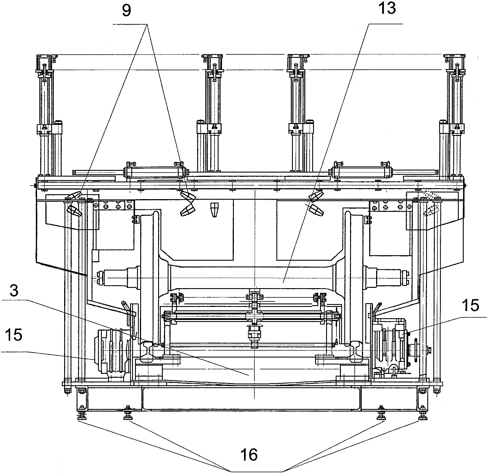
На фиг.1 и фиг.2 в разных проекциях изображено устройство для очистки колесных пар, где приняты следующие обозначения: 1 - камера для мойки Figure 1 and figure 2 in different projections shows a device for cleaning wheelsets, where the following notation: 1 - camera for washing
колесной пары; 2 - защитный кожух; 3 - отстойник; 4 - направляющие механизма базирования колесной пары; 5 - ведущий ролик; 6 - опорный ролик; 7 - привод загрузки колесной пары в моечную камеру; 8 - захватное устройство; 9 - гидромониторы; 10 - бак для моющей жидкости; 11 - насос высокого давления; 12 - станция очистки воды; 13 - очищаемая колесная пара; 14 - блок автоматического управления устройством; 15 - привод вращения колесной пары; 16 - привод выгрузки колесной пары из камеры; 17 - виброопоры; 18 - пульт управления; 19 - рама.wheelset; 2 - a protective casing; 3 - sedimentation tank; 4 - guides of the mechanism of basing the wheelset; 5 - driving roller; 6 - supporting roller; 7 - drive loading a pair of wheels in the washing chamber; 8 - gripping device; 9 - hydraulic monitors; 10 - tank for washing liquid; 11 - high pressure pump; 12 - water treatment station; 13 - cleaned wheelset; 14 - block automatic control of the device; 15 - drive rotation of a pair of wheels; 16 - drive unloading a pair of wheels from the camera; 17 - vibration mounts; 18 - control panel; 19 - frame.
Устройство для очистки колесных пар содержит камеру для мойки колесной пары 1, закрываемую защитным кожухом 2. В нижней части камеры имеется отстойник 3, служащий для сбора стекающей в процессе очистки моющей жидкости. Устройство для базирования 4 колесной пары внутри камеры 1 представляет собой приводные ролики 5 и 6, на которых внутри камеры устанавливается колесная пара, один из роликов является ведущим 5, а второй ролик - опорным 6. Подача колесной пары в зону ее очистки осуществляется с помощью манипуляторов, представляющими собой захваты 8 оси колесной пары, приводимыми в действие приводами 7 и 16. Над моющей камерой установлен бак для моющей жидкости 10 с насосом 11, входящие в состав многоступенчатой системы регенерации моющего раствора - станцией очистки оборотной воды 12, Внутри камеры закреплены моющие элементы, выполненные в виде гидромониторов 9, которые направляют моющую струю в любую зону очистки колесной пары 13. Направление моющих струй из гидромониторов 9 автоматически задается программой блока управления 14 с пульта 18. Моющей жидкостью является горячая вода, подаваемая под высоким давлением. Устройство устанавливается на виброопоры 17.A device for cleaning wheelsets contains a chamber for washing wheelsets 1, which is closed by a protective casing 2. In the lower part of the chamber there is a sump 3, which serves to collect the detergent that flows during the cleaning process. A device for basing a 4-wheel pair inside the chamber 1 is a drive roller 5 and 6, on which a pair of wheels is mounted inside the chamber, one of the rollers is the drive 5, and the second roller is the reference 6. The wheel pair is fed to the cleaning zone using manipulators , which are captures 8 of the axis of the wheelset, driven by drives 7 and 16. Above the washing chamber there is a tank for washing liquid 10 with a pump 11, which are part of a multi-stage system for the regeneration of a washing solution - a cleaning station and circulating water 12, Inside the chamber there are fixed washing elements made in the form of hydromonitors 9, which direct the washing jet to any cleaning zone of the wheelset 13. The direction of the washing jets from the hydromonitors 9 is automatically set by the program of the control unit 14 from the console 18. The washing liquid is hot water supplied under high pressure. The device is mounted on vibration mounts 17.
Устройство работает в автоматическом режиме, обеспечивая загрузку колесной пары в камеру мойки одним из манипуляторов с захватами, ее мойку и очистку, выгрузку колесной пары из камеры другим манипулятором с захватами. Перед началом работы оператор задает в зависимости от степени загрязнения колесной пары необходимую температуру моющего раствора и длительность процесса мойки. После перемещения защитного кожуха 2 моющая камера 1 открывается, грязная колесная пара 13 с помощью захвата 8 манипулятора загружается в камеру для мойки 1 на устройство ее базирования 4. После установки колесной пары защитный кожух 2 закрывает камеру 1, и механизм очистки начинает работу в автоматическом режиме. Запускаются The device operates in automatic mode, providing loading of the wheelset into the washing chamber by one of the manipulators with grippers, its washing and cleaning, unloading of the wheelset from the chamber by another manipulator with grippers. Before starting work, the operator sets the necessary temperature of the washing solution and the duration of the washing process, depending on the degree of contamination of the wheelset. After moving the protective casing 2, the washing chamber 1 opens, the dirty wheelset 13 is loaded into the washing chamber 1 by means of the gripper 8 of the manipulator 4, and its basing device 4. After the wheelset is installed, the protective casing 2 closes the chamber 1, and the cleaning mechanism starts to work in automatic mode . Start up
электродвигатели приводов насосов высокого давления 11 и привода вращения колесной пары 15. Гидромониторы 9 нацеливают струи очищающей жидкости на участки очистки колесной пары 13, подавая их в нужном направлении на определенное время в соответствии с заданной программой. По истечении заданного времени мойки все электродвигатели отключаются. На индикаторе пульта 18 высвечивается сообщение об окончании процесса очистки. Защитный кожух 2 камеры 1 поднимается, манипулятор с захватами 8 выгружает вымытую колесную пару 13 из камеры 1. Цикл мойки завершен и устройство готово к приему следующей грязной колесной пары.electric motors of the drives of the high pressure pumps 11 and the drive of rotation of the wheelset 15. Hydromonitors 9 aim the jets of cleaning liquid on the cleaning areas of the wheelsets 13, feeding them in the right direction for a certain time in accordance with a given program. After the set washing time has elapsed, all electric motors are switched off. On the indicator of the remote 18 displays a message about the end of the cleaning process. The protective casing 2 of the chamber 1 rises, the manipulator with grabs 8 unloads the washed wheelset 13 from the chamber 1. The washing cycle is completed and the device is ready to receive the next dirty wheelset.
Технический результат использования данного изобретения состоит в надежности и упрощении конструкции очистительных элементов. Это обеспечивается за счет использования таких элементов, которые не входят в непосредственный контакт с колесной парой и не загрязняются. Хорошая очистка труднодоступных мест колесной пары обеспечивается прицельным попаданием моющего раствора под высоким давлением и необходимым временем его воздействия на очищаемую поверхность. Экономия моющей жидкости происходит за счет использования многоступенчатой системы эффективной очистки моющей жидкости, позволяющей многократно использовать ее в технологическом процессе мойки колесной пары. Установка устройства на виброопорах позволяет не сооружать для него массивного фундамента. Использование в конструкции устройства базирования колесной пары приводных роликов - ведущего и опорного дает возможность производить мойку колесных пар различной конструкции и размеров, делая ее универсальной. Установка бака с моющей жидкостью в составе станции очистки воды над моющей камерой позволяет значительно уменьшить занимаемую устройством площадь.The technical result of the use of this invention is the reliability and simplification of the design of the cleaning elements. This is achieved through the use of elements that are not in direct contact with the wheelset and are not contaminated. Good cleaning of hard-to-reach places of the wheelset is ensured by targeted hit of the washing solution under high pressure and the necessary time of its impact on the surface being cleaned. Saving of the washing liquid occurs due to the use of a multi-stage system of effective cleaning of the washing liquid, which allows its multiple use in the technological process of washing the wheelset. Installing the device on vibration mounts allows you not to build a massive foundation for it. The use of the drive wheels — drive and support wheelsets in the design of the device for basing the wheelset — makes it possible to wash wheelsets of various designs and sizes, making it universal. Installing a tank with washing liquid as part of a water treatment station above the washing chamber can significantly reduce the area occupied by the device.
Источники информации.Information sources.
1 - Патент RU №2216413, МКИ В08 В1/04, B60S 3/06, заявка от 2001.12.10.1 - Patent RU No. 2216413, MKI B08 B1 / 04, B60S 3/06, application of 2001.12.10.
2 - Попов Ю.В., Калмычков В.А., Беляев В.А. «Автоматизированный комплекс для мойки колесных пар», журнал «Вагоны и вагонное хозяйство, 2005 год, №4, стр.34.2 - Popov Yu.V., Kalmychkov V.A., Belyaev V.A. “Automated complex for washing wheelsets”, magazine “Wagons and carriages, 2005, No. 4, p. 34.
3 - Патент RU №2005638, МКИ B60S 3/04, заявка от 1991.12.16.3 - Patent RU No. 20055638, MKI B60S 3/04, application of 1991.12.16.
Claims (1)
Priority Applications (1)
| Application Number | Priority Date | Filing Date | Title |
|---|---|---|---|
| RU2007144421/22U RU71945U1 (en) | 2007-11-29 | 2007-11-29 | WHEEL PAIR CLEANING DEVICE |
Applications Claiming Priority (1)
| Application Number | Priority Date | Filing Date | Title |
|---|---|---|---|
| RU2007144421/22U RU71945U1 (en) | 2007-11-29 | 2007-11-29 | WHEEL PAIR CLEANING DEVICE |
Publications (1)
| Publication Number | Publication Date |
|---|---|
| RU71945U1 true RU71945U1 (en) | 2008-03-27 |
Family
ID=48235258
Family Applications (1)
| Application Number | Title | Priority Date | Filing Date |
|---|---|---|---|
| RU2007144421/22U RU71945U1 (en) | 2007-11-29 | 2007-11-29 | WHEEL PAIR CLEANING DEVICE |
Country Status (1)
| Country | Link |
|---|---|
| RU (1) | RU71945U1 (en) |
Cited By (1)
| Publication number | Priority date | Publication date | Assignee | Title |
|---|---|---|---|---|
| RU2629829C1 (en) * | 2016-10-26 | 2017-09-04 | Открытое Акционерное Общество "Научно-Исследовательский И Проектно-Конструкторский Институт Информатизации, Автоматизации И Связи На Железнодорожном Транспорте" | System for contamination control and cleaning of car wheels before detaching trains on gravity hump |
-
2007
- 2007-11-29 RU RU2007144421/22U patent/RU71945U1/en not_active IP Right Cessation
Cited By (1)
| Publication number | Priority date | Publication date | Assignee | Title |
|---|---|---|---|---|
| RU2629829C1 (en) * | 2016-10-26 | 2017-09-04 | Открытое Акционерное Общество "Научно-Исследовательский И Проектно-Конструкторский Институт Информатизации, Автоматизации И Связи На Железнодорожном Транспорте" | System for contamination control and cleaning of car wheels before detaching trains on gravity hump |
Similar Documents
| Publication | Publication Date | Title |
|---|---|---|
| US6609962B1 (en) | Dressing apparatus and polishing apparatus | |
| CN111871926A (en) | Industrial cleaning device | |
| CN106076945A (en) | Mixed flow cleaning machine | |
| KR101415071B1 (en) | Polishing machine comprising sliding means transverse to the front face | |
| CN112191584A (en) | Equipment for removing oil dirt of shell part and working method | |
| CN109909224A (en) | A kind of automatic temperature-controlled supersonic wave cleaning machine of rotary multistation supporting plate lift | |
| CN210146562U (en) | Automatic temperature control ultrasonic cleaner of rotatory multistation layer board over-and-under type | |
| CN105170590B (en) | A kind of full-automatic barrel washer | |
| CN201482762U (en) | Automatic cleaning machine for outer tube of all-glass vacuum solar heat collecting tube | |
| RU2348553C1 (en) | Washing machine for automated cleaning of mechanical parts and components | |
| CN205851469U (en) | Mixed flow cleaning machine | |
| RU71945U1 (en) | WHEEL PAIR CLEANING DEVICE | |
| CN209503790U (en) | A kind of phosphorous copper balls polissoir with dedusting function | |
| CN108994739B (en) | Shot blasting machine special for No. 13 car coupler | |
| CN109719067B (en) | Combined final cleaning equipment for crankshaft | |
| CN206701796U (en) | A kind of medicine equipment cleaning drying device | |
| CN102556005A (en) | Cleaning device for axle box of bullet train | |
| CN212577044U (en) | Steel pipe surface mud remove device for building | |
| CN115771088B (en) | Steel casting grinding device with traction function and traction method | |
| CN109226114B (en) | Industrial saturated steam double-station hydraulic hard tube cleaning machine | |
| RU93707U1 (en) | WASHING AND DRYING UNIT | |
| CN112692017A (en) | Steel bottle inner wall cleaning and drying machine | |
| CN113977396A (en) | Automatic polishing and cleaning system and method for metal construction forming | |
| RU130271U1 (en) | WHEEL PAIR CLEANING DEVICE | |
| CN107932284B (en) | A kind of iron plate removes iron rust device |
Legal Events
| Date | Code | Title | Description |
|---|---|---|---|
| MM1K | Utility model has become invalid (non-payment of fees) |
Effective date: 20081130 |
|
| NF1K | Reinstatement of utility model |
Effective date: 20100627 |
|
| MM1K | Utility model has become invalid (non-payment of fees) |
Effective date: 20151130 |