RU50126U1 - CENTRIFUGAL GAS-LIQUID SEPARATOR FILTER - Google Patents
CENTRIFUGAL GAS-LIQUID SEPARATOR FILTER Download PDFInfo
- Publication number
- RU50126U1 RU50126U1 RU2005122116/22U RU2005122116U RU50126U1 RU 50126 U1 RU50126 U1 RU 50126U1 RU 2005122116/22 U RU2005122116/22 U RU 2005122116/22U RU 2005122116 U RU2005122116 U RU 2005122116U RU 50126 U1 RU50126 U1 RU 50126U1
- Authority
- RU
- Russia
- Prior art keywords
- gas
- liquid
- perforated
- outlet
- conical
- Prior art date
Links
Landscapes
- Cyclones (AREA)
Abstract
Предложение относится к оборудованию для очистки газа и жидкости от механических примесей и может быть использовано в газовой, нефтяной, энергетической и в других областях промышленности. Центробежный газожидкостный сепараторный фильтр, содержащий вертикальный корпус с конусными крышкой и днищем, которое оборудовано устройством отбора твердых фракций, тангенциальный ввод смеси, осевую трубу, экранирующие конусные пластины, патрубки вывода очищенного газа и жидкости. Осевая труба выполнена в виде набора перфорированных патрубков с фильтрами наружи, нижняя часть которых телескопически вставлена в верхнюю часть другого патрубка с возможностью ограниченного раздвижения. Нижний перфорированный патрубок телескопически входит в патрубок вывода очищенной жидкости, который изогнут в бок, снабжен клапанным узлом, не пропускающим газ, и выполнен с возможностью рециркуляции жидкости. Верхний конец каждого перфорированного патрубка снабжен экранирующими конусными пластинами, причем верхняя экранирующая конусная пластина установлена выше тангенциального ввода и выполнена с возможностью скользящего перемещения относительно корпуса. Верхний перфорированный патрубок, выше верхней экранирующей конусной пластины, жестко соединен с патрубком вывода очищенного газа, который герметично установлен в конусную крышку с возможностью фиксации, осевого перемещения вверх, снабжен клапанным узлом, не пропускающим жидкость, и выполнен с возможностью рециркуляции газа. Верхний конец каждого фильтра герметично присоединен к перфорированному патрубку выше отверстий перфорации, а нижний - к верхнему краю другого перфорированного патрубка, в который вставляется перфорированный патрубок с фильтром. Фильтры выполнены с возможностью увеличивать свою пропускную способность при раздвижении перфорированных патрубков. Суммарная длина раздвижения патрубков не превышает длины выдвижения патрубка вывода очищенного газа из корпуса. Патрубок вывода очищенного газа под конусной крышкой в исходном состоянии дополнительно оборудован каналом с клапаном, пропускающим газ снаружи внутрь. Использование подобной конструкции центробежного газожидкостного сепараторного фильтра позволяет очищать газожидкостную смесь с практически любым содержанием газа в жидкости, вплоть до просто жидкости или газа, исключать засорение жидкости особенно при срыве потока смеси и падении давления, производить самоочистку фильтров, что значительно увеличивает межремонтный период и качество очистки газа и жидкости.The proposal relates to equipment for cleaning gas and liquid from mechanical impurities and can be used in gas, oil, energy and other industries. A centrifugal gas-liquid separator filter containing a vertical casing with a conical cap and a bottom, which is equipped with a device for the selection of solid fractions, a tangential mixture inlet, an axial tube, conical plate shields, purified gas and liquid outlet pipes. The axial tube is made in the form of a set of perforated nozzles with filters outside, the lower part of which is telescopically inserted into the upper part of another nozzle with the possibility of limited expansion. The lower perforated nozzle telescopically enters the outlet of the purified liquid, which is bent to the side, equipped with a valve assembly that does not allow gas to pass, and is configured to recirculate the liquid. The upper end of each perforated nozzle is provided with shielding conical plates, the upper shielding conical plate mounted above the tangential input and made with the possibility of sliding movement relative to the housing. The upper perforated nozzle, above the upper shielding conical plate, is rigidly connected to the outlet of the purified gas outlet, which is hermetically mounted in the conical cover with the possibility of fixation, axial movement upward, equipped with a valve assembly that does not allow liquid to pass through, and is made with the possibility of gas recirculation. The upper end of each filter is hermetically attached to the perforated nozzle above the perforation holes, and the lower end to the upper edge of the other perforated nozzle into which the perforated nozzle with the filter is inserted. Filters are configured to increase their throughput when extending the perforated nozzles. The total length of the extension of the nozzles does not exceed the length of the extension of the outlet pipe of the purified gas from the housing. The outlet pipe of the purified gas under the conical cover in the initial state is additionally equipped with a channel with a valve passing gas from the outside to the inside. Using a similar design of a centrifugal gas-liquid separator filter allows you to clean the gas-liquid mixture with almost any gas content in the liquid, up to just liquid or gas, eliminate clogging of the liquid, especially when the flow of the mixture is cut off and the pressure drops, self-clean the filters, which significantly increases the overhaul period and the quality of cleaning gas and liquid.
Description
Предложение относится к оборудованию для очистки газа и жидкости от механических примесей и может быть использовано в газовой, нефтяной, теплоэнергетической и в других областях промышленности.The proposal relates to equipment for the purification of gas and liquid from mechanical impurities and can be used in gas, oil, heat and other industries.
Известен «Сепаратор» (патент RU №2147914, B 01 D 45/12, опубл. 27.04.2000 г.), содержащий корпус с патрубками входа и неочищенного газа, выхода газа и жидкости, сепарационные элементы, расположенные на тарелке, оборудованной сливной трубой, при этом в нем установлен циклон, входное отверстие трубы входа газа которого смонтировано в полости патрубка входа неочищенного газа, а осевая зона соединена с концом трубы слива жидкости.The well-known "Separator" (patent RU No. 2147914, B 01 D 45/12, publ. 04/27/2000), comprising a housing with nozzles for inlet and raw gas, gas and liquid outlet, separation elements located on a plate equipped with a drain pipe wherein a cyclone is installed in it, the inlet of the gas inlet pipe of which is mounted in the cavity of the raw gas inlet pipe, and the axial zone is connected to the end of the liquid drain pipe.
Одним из недостатков данного устройства является большая металлоемкость, так как циклон находится внутри корпуса, оборудованного сепарационными элементами.One of the disadvantages of this device is its high metal consumption, since the cyclone is located inside a housing equipped with separation elements.
Наиболее близким по технической сущности является «Центробежный двухступенчатый газожидкостной сепаратор» (патент SU №1492522, B 01 D 45/12, опубл. 15.01.1994 г.), содержащий вертикальный корпус, разделенный горизонтальной перегородкой на верхнюю и нижнюю сепарационные камеры, тангенциальный ввод разделяемой смеси, расположенный под перегородкой, осевую трубу, соединяющую верхнюю и нижнюю камеры, установленный с зазором над ней осевой выходной патрубок, экранирующую пластину, расположенную в нижней камере под осевой трубой, рециркуляционную трубу, соединяющую верхнюю и нижнюю камеры, при этом рециркуляционная труба размещена по оси корпуса, один ее конец присоединен к верхней камере через стенку осевой трубы, а другой расположен над экранирующей пластиной с зазором относительно ее поверхности, причем экранирующая пластина выполнена в виде конуса.The closest in technical essence is the "Centrifugal two-stage gas-liquid separator" (patent SU No. 1492522, B 01 D 45/12, publ. 01/15/1994), containing a vertical casing, separated by a horizontal partition on the upper and lower separation chambers, tangential input a separable mixture, located under the partition, an axial pipe connecting the upper and lower chambers, an axial outlet pipe installed with a gap above it, a shielding plate located in the lower chamber under the axial pipe, a recirculation pipe, Connects the upper and lower chambers, the recirculation pipe placed on the axis of the housing, one end is connected to the upper chamber through the wall of the axial pipe and the other is located above the shielding plate with a gap with respect to its surface, wherein the shielding plate is formed as a cone.
Общими недостатками данных устройств являются невозможность отдельно очищать газ и жидкость, вероятность перемешивания жидкости с выделенными при очистке твердыми фракциями, особенно при срыве потока, подаваемого по тангенциальному патрубку, отсутствие возможности самоочистки.Common disadvantages of these devices are the inability to separately purify gas and liquid, the likelihood of mixing the liquid with the solid fractions separated during cleaning, especially when the flow supplied through the tangential pipe is interrupted, and there is no possibility of self-cleaning.
Технической задачей является:The technical challenge is:
во-первых, расширение функциональных возможностей за счет возможности очистки газа и жидкости, а так же освобождения газа при малом содержании жидкости и жидкости при малом содержании газа;firstly, the expansion of functionality due to the possibility of purification of gas and liquid, as well as the release of gas with a low content of liquid and liquid with a low gas content;
во-вторых, увеличение межремонтного периода устройства и качества очистки жидкости и газа за счет добавления функции самоочистки;secondly, the increase in the overhaul period of the device and the quality of cleaning liquid and gas by adding a self-cleaning function;
в-третьих, исключение возможности засорения твердыми фракциями жидкости, в том числе при срыве потока смеси или падении давления.thirdly, the exclusion of the possibility of clogging with solid fractions of the liquid, including when the flow of the mixture is disrupted or the pressure drops.
Техническая задача решается центробежным газожидкостным сепараторным фильтром, содержащим вертикальный корпус, тангенциальный ввод смеси, осевую трубу, экранирующие конусные пластины, патрубки вывода очищенного газа и жидкости.The technical problem is solved by a centrifugal gas-liquid separator filter containing a vertical casing, a tangential mixture inlet, an axial tube, conical shielding plates, purified gas and liquid outlet pipes.
Новым является то, что корпус снизу и сверху соответственно оснащен конусными крышкой и днищем, а конусное днище снизу оборудовано устройством отбора твердых фракций, причем осевая труба выполнена в виде набора перфорированных патрубков, нижняя часть которых телескопически вставлена в верхнюю часть другого патрубка с возможностью ограниченного раздвижения, при этом нижний перфорированный патрубок телескопически входит в патрубок вывода очищенной жидкости, который изогнут в бок, снабжен клапанным узлом, не пропускающим газ, и выполнен с возможностью рециркуляции жидкости при раздвинутом состоянии перфорированных патрубков, а экранирующими конусными пластинами снабжен верхний конец каждого перфорированного патрубка, причем верхняя экранирующая конусная пластина установлена выше тангенциального ввода и выполнена с возможностью скользящего перемещения относительно корпуса, при этом верхний перфорированный патрубок выше этой экранирующей конусной пластины жестко соединен с патрубком вывода очищенного газа, который герметично установлен в конусную крышку с возможностью фиксации, осевого перемещения вверх и снабжен клапанным узлом, не пропускающим жидкость, и выполнен с возможностью рециркуляции газа при раздвинутом состоянии перфорированных патрубков, причем отверстия перфорированных патрубков снаружи перекрыты фильтрами, верхний конец которых герметично присоединен к перфорированному патрубку выше отверстий перфорации, а нижний - к верхнему краю другого перфорированного патрубка, в который вставляется перфорированный патрубок с фильтром, причем фильтры выполнены с возможностью увеличивать свою пропускную способность при раздвижении перфорированных патрубков, а суммарная длина раздвижения патрубков не превышает длины выдвижения патрубка вывода очищенного газа из корпуса, при этом патрубок вывода очищенного газа под конусной крышкой в исходном состоянии дополнительно оборудован каналом с клапаном, пропускающим газ снаружи внутрь.What is new is that the casing is equipped with a conical cover and a bottom, respectively, from the bottom and top, while the conical bottom is equipped with a device for selecting solid fractions, the axial tube being made as a set of perforated pipes, the lower part of which is telescopically inserted into the upper part of another pipe with the possibility of limited expansion while the lower perforated pipe telescopically enters the pipe outlet of the purified liquid, which is bent to the side, equipped with a valve assembly that does not allow gas to pass, and is made with the possibility of recirculation of the liquid when the perforated nozzles are apart, and the shielding conical plates are provided with the upper end of each perforated nozzle, the upper shielding conical plate mounted above the tangential entry and made with sliding movement relative to the housing, while the upper perforated nozzle is rigidly above this shielding conical plate connected to the outlet pipe of the purified gas, which is hermetically installed in a conical cover with with fixation, axial movement up and equipped with a valve assembly that does not allow fluid to pass through and is configured to recirculate gas when the perforated nozzles are apart, the holes of the perforated nozzles are externally blocked by filters, the upper end of which is hermetically attached to the perforated nozzle above the perforation holes, and the lower to the upper edge of another perforated pipe into which a perforated pipe with a filter is inserted, the filters being made with the possibility of increasing maintain its throughput capacity when extending the perforated nozzles, and the total extension length of the nozzles does not exceed the extension length of the purified gas outlet pipe from the housing, while the purified gas outlet pipe under the conical cover in the initial state is additionally equipped with a channel with a valve passing gas from outside to inside.
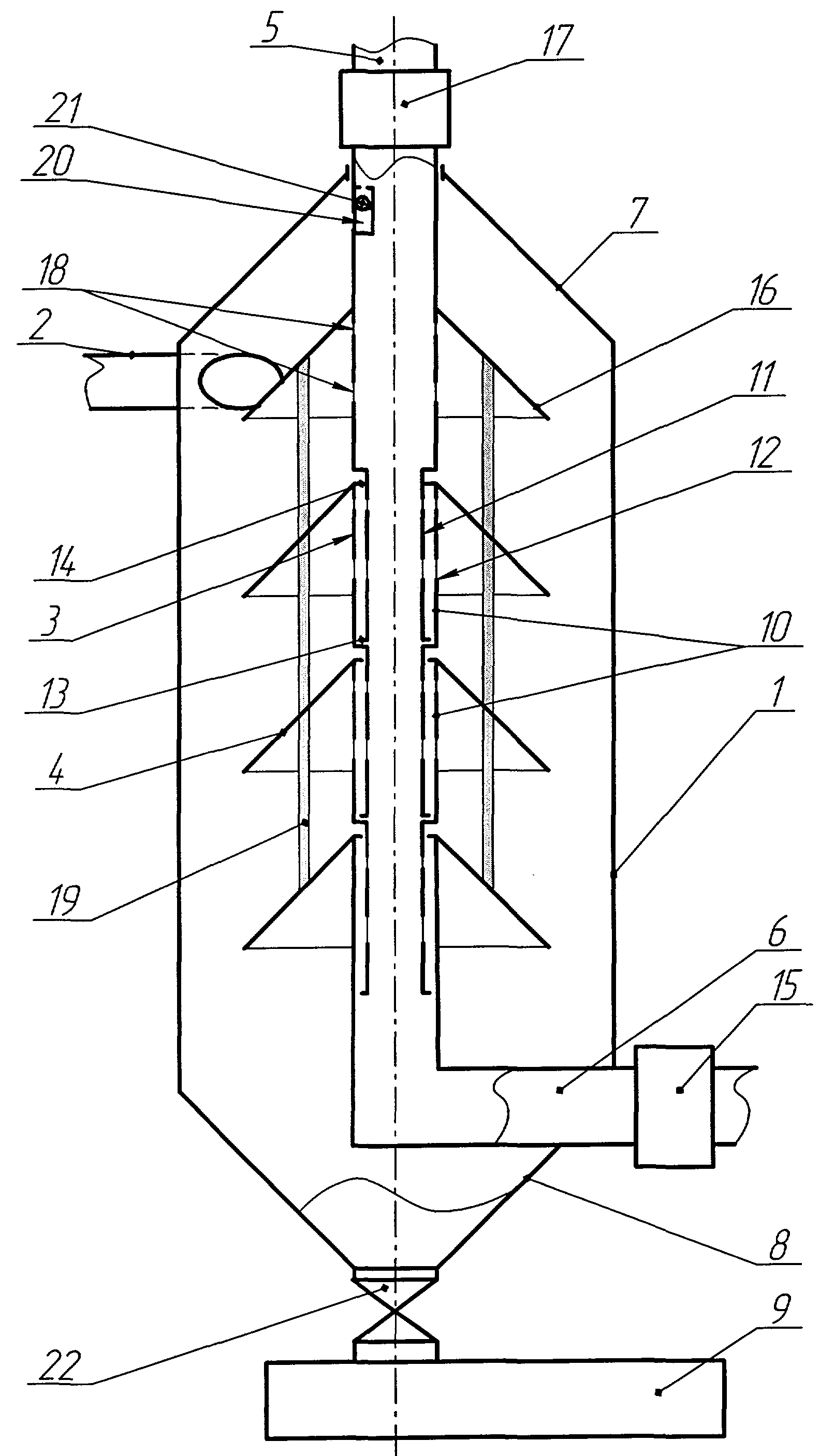
На чертеже изображена схема центробежного газожидкостного сепараторного фильтра в поперечном разрезе.The drawing shows a diagram of a centrifugal gas-liquid separator filter in cross section.
Центробежный сепараторный фильтр содержит вертикальный корпус 1, тангенциальный ввод 2 смеси, осевую трубу 3, экранирующие конусные пластины 4, патрубки вывода очищенного газа 5 и жидкости 6. Корпус 1 снизу и сверху соответственно оснащен The centrifugal separator filter contains a vertical housing 1, a tangential input 2 of the mixture, an axial tube 3, shielding conical plates 4, outlet pipes for the purified gas 5 and liquid 6. The housing 1 is equipped with a bottom and top, respectively
конусными крышкой 7 и днищем 8, а конусное днище снизу оборудовано устройством отбора твердых фракций 9. Осевая труба 3 выполнена в виде набора перфорированных патрубков 10, нижняя часть 11 которых телескопически вставлена в верхнюю часть 12 другого патрубка 10 с возможностью ограниченного упорами 13 и 14 раздвижения. Нижний перфорированный патрубок 10 телескопически входит в патрубок вывода 6 очищенной жидкости, который изогнут в бок, снабжен клапанным узлом 15, не пропускающим газ, и выполнен с возможностью рециркуляции жидкости при раздвинутом состоянии перфорированных патрубков 10. Экранирующими конусными пластинами 4 снабжен верхний конец каждого перфорированного патрубка 10, причем верхняя экранирующая конусная пластина 16 установлена выше тангенциального ввода 2 и выполнена с возможностью скользящего перемещения относительно корпуса 1. Верхний перфорированный патрубок 10, выше этой экранирующей конусной пластины 16, жестко соединен с патрубком 5 вывода очищенного газа, который герметично установлен в конусную крышку 7 с возможностью фиксации, осевого перемещения вверх, снабжен клапанным узлом 17, не пропускающим жидкость, и выполнен с возможностью рециркуляции газа при раздвинутом состоянии перфорированных патрубков 10. Отверстия 18 перфорированных патрубков 10 перекрыты снаружи фильтрами 19. Верхний конец каждого из фильтров 19 герметично присоединен к перфорированному патрубку 10 выше отверстий 18, а нижний - к верхнему краю другого перфорированного патрубка 10, в который вставляется перфорированный патрубок 10 с фильтром 19. Фильтры 19 выполнены с возможностью увеличивать свою пропускную способность при раздвижении перфорированных патрубков 10, а суммарная длина раздвижения патрубков 10 не превышает длины выдвижения патрубка вывода очищенного газа 5 из корпуса 1. Патрубок 5 вывода очищенного газа под конусной крышкой 7 в исходном состоянии дополнительно оборудован каналом 20 с клапаном 21, пропускающим газ снаружи внутрь.a conical cap 7 and a bottom 8, and the bottom cone bottom is equipped with a device for selecting solid fractions 9. The axial tube 3 is made in the form of a set of perforated nozzles 10, the lower part 11 of which is telescopically inserted into the upper part 12 of another nozzle 10 with the possibility of sliding apart by stops 13 and 14 . The lower perforated nozzle 10 telescopically enters the nozzle of the outlet 6 of the purified liquid, which is bent laterally, equipped with a valve assembly 15 that does not allow gas to pass, and is configured to recirculate the liquid when the perforated nozzles 10 are extended. Shielding conical plates 4 are provided with the upper end of each perforated nozzle 10, and the upper shielding conical plate 16 is installed above the tangential input 2 and is made with the possibility of sliding movement relative to the housing 1. The upper the perforated pipe 10, above this shielding conical plate 16, is rigidly connected to the purified gas outlet pipe 5, which is hermetically mounted in the conical cover 7 with the possibility of fixation, axial movement upward, equipped with a valve assembly 17 that does not allow liquid to pass through, and is configured to recycle gas when the perforated nozzles 10 are extended, the holes 18 of the perforated nozzles 10 are blocked externally by the filters 19. The upper end of each of the filters 19 is hermetically connected to the perforated nozzle 10 in holes 18, and the lower one to the upper edge of another perforated nozzle 10, into which the perforated nozzle 10 with the filter 19 is inserted. The filters 19 are configured to increase their throughput when the perforated nozzles 10 are extended, and the total extension length of the nozzles 10 does not exceed the extension length the outlet pipe of the purified gas 5 from the housing 1. The pipe 5 of the outlet of the purified gas under the conical cover 7 in the initial state is additionally equipped with a channel 20 with a valve 21 that allows gas to pass from the outside to the inside.
Центробежный газожидкостный сепараторный фильтр работает следующим образом:A centrifugal gas-liquid separator filter operates as follows:
Перед началом работы патрубок вывода очищенного газа 5 фиксируют в нижнем положении относительно конусной крышки 7 корпуса 1. Затем газожидкостная смесь подается с высокой скоростью по тангенциальному вводу 2 в вертикальный корпус 1, где данная смесь под действием сил инерции и тяжести образует спиралевидный поток, направленный вниз, причем, чем тяжелее фракции, тем дальше они располагаются от центральной оси корпуса 1. В результате твердые тяжелые фракции газожидкостной смеси по стенкам корпуса 1 спускаются в конусное днище 8, снизу которого они отбираются устройством отбора твердых фракций 9. На практике в виде данного устройства 9 использовались Before starting work, the outlet pipe of the purified gas 5 is fixed in the lower position relative to the conical cover 7 of the housing 1. Then the gas-liquid mixture is supplied at a high speed along the tangential inlet 2 into the vertical housing 1, where this mixture under the action of inertia and gravity forms a spiral flow downward moreover, the heavier the fraction, the farther they are from the central axis of the housing 1. As a result, the solid heavy fractions of the gas-liquid mixture along the walls of the housing 1 descend into the conical bottom 8, from the bottom of which They are selected on the device selection solids 9. In practice, as the device 9 used
шнек с выходным клапаном, регулирующим степень отжима, (на черт. не показан), или отстойная камера, которую очищали по мере необходимости при закрытом вентиле 22. Очищенная газожидкостная смесь отжимается к центральной оси корпуса 1, откуда она попадает через фильтры 19 и отверстия 18 перфорированных патрубков 10 в осевую трубу 3. Наличие экранирующих конусных пластин 4 и 16 и фильтров 19 исключает засорение очищенной газожидкостной смеси отбираемой из осевой трубы 3 при срыве потока или падении давления в тангенциальном вводе 2. При входе в корпус 1 из тангенциального ввода 2 смесь попадает в зону разряжения, так как площадь поперечного сечения корпуса 1 превосходит площадь поперечного сечения тангенциального ввода 2, при этом при вращении смеси в корпусе 1, в зоне близкой к его оси, также создается разряжение, что в совокупности вызывает интенсивное выделение газа из газожидкостной смеси. Выделенный газ, проходя по экранирующим конусным пластинам 4 и 16 снизу, через фильтры 19, отверстия 18 перфорированных патрубков 10 осевой трубы 3 отбирается патрубком вывода очищенного газа 5. Оставшаяся очищенная жидкость из осевой трубы 3 отбирается патрубком вывода очищенной жидкости 6, который выведен сбоку корпуса 1, чтобы не мешать интенсивному отбору твердых фракций из конусного днища 8. Верхняя экранирующая конусная пластина 16 установлена выше тангенциального ввода 2 и выполнена большего диаметра, чем остальные экранирующие конусные пластины 4, с возможностью скользящего перемещения относительно корпуса 1, что исключает попадание твердых фракций газожидкостной смеси в зону корпуса 1, расположенную выше верхней экранирующей конусной пластины 16. Собирающийся под конусной крышкой 7 газ отводится по патрубку вывода очищенного газа 5 через канал 20 с клапаном 21.a screw with an outlet valve that controls the degree of extraction (not shown in the drawing), or a settling chamber, which was cleaned as necessary with the valve 22 closed. The cleaned gas-liquid mixture is pressed to the central axis of the housing 1, from where it enters through filters 19 and openings 18 perforated nozzles 10 into the axial tube 3. The presence of shielding conical plates 4 and 16 and filters 19 eliminates the clogging of the cleaned gas-liquid mixture taken from the axial tube 3 when the flow is cut off or pressure drops in the tangential inlet 2. When entering the housing 1, from a tangential input 2, the mixture enters the rarefaction zone, since the cross-sectional area of the housing 1 exceeds the cross-sectional area of the tangential input 2, and when the mixture rotates in the housing 1, in a zone close to its axis, a vacuum is also created, which together causes intensive gas evolution from a gas-liquid mixture. The evolved gas passing through the shielding conical plates 4 and 16 from the bottom through the filters 19, the holes 18 of the perforated nozzles 10 of the axial pipe 3 is selected by the purified gas outlet pipe 5. The remaining purified liquid from the axial pipe 3 is taken away by the purified liquid outlet pipe 6, which is led out from the side of the housing 1, so as not to interfere with the intensive selection of solid fractions from the conical bottom 8. The upper shielding conical plate 16 is installed above the tangential input 2 and made larger in diameter than the other shielding conical plate 4, with the possibility of sliding movement relative to the housing 1, which eliminates the ingress of solid fractions of the gas-liquid mixture into the zone of the housing 1, located above the upper shielding conical plate 16. The gas collected under the conical cover 7 is discharged through the clean gas outlet 5 through the channel 20 with the valve 21 .
В случаях, когда в газожидкостной смеси содержится очень малое количество растворенного газа, очищенная жидкость может подниматься по патрубку вывода 5 очищенного газа и далее в систему отбора газа (на чертеже не показана). Поэтому, чтобы исключить попадание жидкости в систему отбора газа, патрубок 5 вывода очищенного газа снабжен клапанным узлом 17, не пропускающим жидкость. Клапанный узел 17 на практике был выполнен в виде поплавкового клапана (на чертеже не показан), который при превышении уровня жидкости выше допустимого перекрывал проходной канал (на черт. не показан) патрубка 5 вывода очищенного газа.In cases where a very small amount of dissolved gas is contained in the gas-liquid mixture, the purified liquid can rise through the outlet pipe 5 of the purified gas and then into the gas extraction system (not shown in the drawing). Therefore, in order to prevent liquid from entering the gas extraction system, the purified gas outlet pipe 5 is provided with a valve assembly 17 that does not allow liquid to pass through. The valve assembly 17 in practice was made in the form of a float valve (not shown in the drawing), which, when the liquid level was above the permissible level, blocked the passage channel (not shown in the drawing) of the purified gas outlet pipe 5.
В случаях, когда в газожидкостной смеси очень большое количество растворенного газа, очищенный газ может попадать в патрубок 6 вывода очищенной жидкости и далее в систему отбора жидкости (на чертеже не показана). Поэтому, чтобы исключить попадание газа в систему отбора жидкости, патрубок 6 вывода очищенной жидкости снабжен клапанным узлом 15, не пропускающим газ. Этот клапанный узел 15 был выполнен In cases where the gas-liquid mixture has a very large amount of dissolved gas, the purified gas can enter the outlet 6 of the outlet of the purified liquid and then to the liquid withdrawal system (not shown in the drawing). Therefore, in order to prevent the ingress of gas into the fluid extraction system, the outlet pipe 6 of the purified liquid is equipped with a valve assembly 15 that does not allow gas to pass through. This valve assembly 15 was made
на практике в виде байпасной линии с поплавковым клапаном (на чертеже не показаны), который при снижении уровня жидкости ниже допустимого перекрывал проходной канал (на черт. не показан) патрубка 6 вывода очищенной жидкости.in practice, in the form of a bypass line with a float valve (not shown in the drawing), which, when the liquid level drops below the permissible level, blocked the passage channel (not shown in the drawing) of the purified liquid outlet pipe 6.
На практике так же применялись клапанные узлы 15 и 17 в виде электронных клапанов, работающих в зависимости от уровня жидкости в осевой трубе 3.In practice, valve assemblies 15 and 17 were also used in the form of electronic valves operating depending on the liquid level in the axial tube 3.
Фильтры 19 выполнены с возможностью увеличивать свою пропускную способность при растяжении перфорированных патрубков 10 осевой трубы 3 за счет увеличения поперечного сечения фильтрующих каналов (на чертеже не показаны). Для получения подобных свойств на практике фильтры 19 были изготовлены двух видов:Filters 19 are configured to increase their throughput by stretching the perforated nozzles 10 of the axial tube 3 by increasing the cross section of the filter channels (not shown). To obtain such properties in practice, filters 19 were made of two types:
первый, в виде сплетенной из проволоки сетки (типа «сетка-рабица»), которая позволяет увеличивать при своем растяжении поперечное сечение фильтрующих каналов фильтра 19 в 3-4 раза;the first, in the form of a mesh woven from wire (type “mesh-netting”), which allows you to increase the cross-section of the filter channels of the filter 19 by 3-4 times when stretched;
второй, в виде сплетенных колец (типа «кольчуга»), которая позволяет увеличивать при своем растяжении поперечное сечение фильтрующих каналов фильтра 19 в 2,5-3 раза, но при этом отличается удобством в ремонте.the second, in the form of woven rings (type "chain mail"), which allows you to increase, when stretched, the cross section of the filter channels of the filter 19 by 2.5-3 times, but at the same time it is convenient to repair.
Согласно требованиям качества очистки, производят замеры величины и количества твердых фракций в очищенном газе и очищенной жидкости. Если качество очистки перестало соответствовать заданным требованиям (например, ГОСТа), то, следовательно, фильтр 19 необходимо прочистить. Для этого устройство останавливают, патрубок вывода очищенного газа 5 вытягивают максимально вверх относительно конусной крышки 7 с последующей фиксацией. В результате нижние части 11 перфорированных патрубков выдвигаются из верхних частей 12 других перфорированных патрубков 10 до взаимодействия всех упоров 13 и 14 между собой благодаря тому, что суммарная длина раздвижения патрубков 10 не превышает длины выдвижения патрубка 5 вывода очищенного газа из корпуса 1. Так как верхний конец каждого из фильтров 19 герметично присоединен к перфорированному патрубку 10 выше отверстий 18, а нижний - к верхнему краю другого перфорированного патрубка 10, в который вставляется перфорированный патрубок 10 с фильтром 19, то с раздвижением перфорированных патрубков 10 фильтры 19 растягиваются, увеличивая свою пропускную способность. При этом верхняя экранирующая конусная пластина 16 вытесняет из полости корпуса 1, расположенной над ней, практически все отложения, жидкость и/или газ (в случаях их задавливания в процессе работы в эту полость) благодаря тому, что крышка 7 выполнена конусной, и между ней и верхней экранирующей конусной пластиной 16 практически не остается места при выдвинутом положении патрубка 5 вывода очищенного газа. После чего патрубок 5 вывода очищенного газа или патрубок 6 вывода очищенной жидкости переводят в режим рециркуляции, то According to the requirements of the quality of cleaning, measure the size and quantity of solid fractions in the purified gas and purified liquid. If the quality of the cleaning has ceased to meet the specified requirements (for example, GOST), then, therefore, the filter 19 must be cleaned. To do this, the device is stopped, the outlet pipe of the purified gas 5 is pulled up as far as possible relative to the conical cover 7 with subsequent fixation. As a result, the lower parts 11 of the perforated nozzles extend from the upper parts 12 of the other perforated nozzles 10 until all the stops 13 and 14 interact with each other due to the fact that the total extension length of the nozzles 10 does not exceed the extension length of the purified gas outlet pipe 5 from the housing 1. Since the upper the end of each of the filters 19 is hermetically connected to the perforated pipe 10 above the holes 18, and the lower one to the upper edge of the other perforated pipe 10 into which the perforated pipe 10 with the filter is inserted Ohm 19, then with the extension of the perforated nozzles 10, the filters 19 are stretched, increasing their throughput. In this case, the upper shielding conical plate 16 displaces practically all deposits, liquid and / or gas (in cases of crushing during operation into this cavity) from the cavity of the housing 1 located above it, due to the fact that the cover 7 is conical and between and the upper shielding conical plate 16 there is practically no space when the position of the outlet pipe 5 of the purified gas outlet is extended. After which the pipe 5 of the outlet of the purified gas or the pipe 6 of the outlet of the purified liquid is transferred to the recirculation mode, then
есть обратной продувки (промывки) фильтра 19. В результате фильтр 19 очищается. Далее патрубок 5 очищенного газа опускают в исходное состояние и фиксируют относительно конусной крышки 7.there is a reverse purge (flushing) of the filter 19. As a result, the filter 19 is cleaned. Next, the pipe 5 of the purified gas is lowered to its original state and fixed relative to the conical cover 7.
Затем центробежный газожидкостный сепараторный фильтр снова запускают в работу.Then the centrifugal gas-liquid separator filter is again put into operation.
Использование подобной конструкции центробежного газожидкостного сепараторного фильтра позволяет очищать газожидкостную смесь с практически любым содержанием газа в жидкости, вплоть до просто жидкости или газа, исключать засорение жидкости особенно при срыве потока смеси и падении давления, производить самоочистку фильтров, что значительно увеличивает межремонтный период устройства и качество очистки газа и жидкости.Using a similar design of a centrifugal gas-liquid separator filter allows you to clean the gas-liquid mixture with almost any gas content in the liquid, up to just liquid or gas, eliminate clogging of the liquid, especially when the flow of the mixture is cut off and the pressure drops, self-clean the filters, which significantly increases the overhaul period of the device and the quality gas and liquid purification.
Claims (1)
Priority Applications (1)
| Application Number | Priority Date | Filing Date | Title |
|---|---|---|---|
| RU2005122116/22U RU50126U1 (en) | 2005-07-12 | 2005-07-12 | CENTRIFUGAL GAS-LIQUID SEPARATOR FILTER |
Applications Claiming Priority (1)
| Application Number | Priority Date | Filing Date | Title |
|---|---|---|---|
| RU2005122116/22U RU50126U1 (en) | 2005-07-12 | 2005-07-12 | CENTRIFUGAL GAS-LIQUID SEPARATOR FILTER |
Publications (1)
| Publication Number | Publication Date |
|---|---|
| RU50126U1 true RU50126U1 (en) | 2005-12-27 |
Family
ID=35870636
Family Applications (1)
| Application Number | Title | Priority Date | Filing Date |
|---|---|---|---|
| RU2005122116/22U RU50126U1 (en) | 2005-07-12 | 2005-07-12 | CENTRIFUGAL GAS-LIQUID SEPARATOR FILTER |
Country Status (1)
| Country | Link |
|---|---|
| RU (1) | RU50126U1 (en) |
Cited By (1)
| Publication number | Priority date | Publication date | Assignee | Title |
|---|---|---|---|---|
| RU190070U1 (en) * | 2018-12-25 | 2019-06-17 | Федеральное государственное автономное образовательное учреждение высшего образования "Сибирский федеральный университет" (СФУ) | CENTRIFUGAL-VORTEX APPARATUS FOR OIL CLEANING FROM HYDROGEN |
-
2005
- 2005-07-12 RU RU2005122116/22U patent/RU50126U1/en not_active IP Right Cessation
Cited By (1)
| Publication number | Priority date | Publication date | Assignee | Title |
|---|---|---|---|---|
| RU190070U1 (en) * | 2018-12-25 | 2019-06-17 | Федеральное государственное автономное образовательное учреждение высшего образования "Сибирский федеральный университет" (СФУ) | CENTRIFUGAL-VORTEX APPARATUS FOR OIL CLEANING FROM HYDROGEN |
Similar Documents
| Publication | Publication Date | Title |
|---|---|---|
| US7014756B2 (en) | Method and apparatus for separating immiscible phases with different densities | |
| KR101004047B1 (en) | Vortex type treatment apparatus for early rainwater with a screen | |
| RU2290252C1 (en) | Centrifugal gas-and-liquid separator filter | |
| RU80768U1 (en) | CENTRIFUGAL GAS-LIQUID SEPARATOR | |
| RU50126U1 (en) | CENTRIFUGAL GAS-LIQUID SEPARATOR FILTER | |
| CN207296930U (en) | A kind of liquid-gas separator | |
| CN201940134U (en) | Fresh air filter | |
| RU49459U1 (en) | CENTRIFUGAL GAS-LIQUID SEPARATOR FILTER | |
| RU2311945C1 (en) | Centrifugal gas-and-liquid separator | |
| CN210193600U (en) | Micro-jet magnetic cyclone dirt separator | |
| US3376977A (en) | System for separating solids from an oil-water fluid mixture | |
| DE102004030350A1 (en) | Vacuum cleaner, has liquid precipitator with cyclone having inlet, outlet and discharge unit, where air is supplied across inlet to cyclone and released across outlet, and precipitated liquid is guided back across unit into filling space | |
| RU2252813C1 (en) | Gas drying separator | |
| RU54530U1 (en) | CENTRIFUGAL GAS-LIQUID SEPARATOR FILTER | |
| RU2290984C1 (en) | Centrifugal gas-liquid separation filter | |
| CN214319435U (en) | Solid-containing waste water separation device | |
| RU2288359C1 (en) | Filter-separator for cleaning and coarse drying of methane gas | |
| RU56208U1 (en) | GAS-LIQUID SEPARATOR | |
| KR102022187B1 (en) | Strainer device | |
| RU2379120C1 (en) | Centrifugal return-uniflow separator | |
| RU2295999C1 (en) | Centrifugal gas-and-liquid separator filter | |
| RU2460571C1 (en) | Device for transported gas treatment | |
| RU116487U1 (en) | INSTALLATION FOR SEPARATION OF AIR AND VAPORS FROM LIQUID | |
| RU2509886C1 (en) | Natural gas cleaning separator | |
| RU59435U1 (en) | CENTRIFUGAL GAS-LIQUID SEPARATOR |
Legal Events
| Date | Code | Title | Description |
|---|---|---|---|
| MM1K | Utility model has become invalid (non-payment of fees) |
Effective date: 20070713 |