RU2631443C2 - Multi-channel discharge distribution device for spreading the binder suspension - Google Patents
Multi-channel discharge distribution device for spreading the binder suspension Download PDFInfo
- Publication number
- RU2631443C2 RU2631443C2 RU2014118730A RU2014118730A RU2631443C2 RU 2631443 C2 RU2631443 C2 RU 2631443C2 RU 2014118730 A RU2014118730 A RU 2014118730A RU 2014118730 A RU2014118730 A RU 2014118730A RU 2631443 C2 RU2631443 C2 RU 2631443C2
- Authority
- RU
- Russia
- Prior art keywords
- outlet
- inlet
- channel
- axis
- suspension
- Prior art date
Links
Images


Classifications
-
- F—MECHANICAL ENGINEERING; LIGHTING; HEATING; WEAPONS; BLASTING
- F17—STORING OR DISTRIBUTING GASES OR LIQUIDS
- F17D—PIPE-LINE SYSTEMS; PIPE-LINES
- F17D1/00—Pipe-line systems
- F17D1/08—Pipe-line systems for liquids or viscous products
-
- B—PERFORMING OPERATIONS; TRANSPORTING
- B28—WORKING CEMENT, CLAY, OR STONE
- B28B—SHAPING CLAY OR OTHER CERAMIC COMPOSITIONS; SHAPING SLAG; SHAPING MIXTURES CONTAINING CEMENTITIOUS MATERIAL, e.g. PLASTER
- B28B19/00—Machines or methods for applying the material to surfaces to form a permanent layer thereon
- B28B19/0092—Machines or methods for applying the material to surfaces to form a permanent layer thereon to webs, sheets or the like, e.g. of paper, cardboard
-
- B—PERFORMING OPERATIONS; TRANSPORTING
- B28—WORKING CEMENT, CLAY, OR STONE
- B28C—PREPARING CLAY; PRODUCING MIXTURES CONTAINING CLAY OR CEMENTITIOUS MATERIAL, e.g. PLASTER
- B28C5/00—Apparatus or methods for producing mixtures of cement with other substances, e.g. slurries, mortars, porous or fibrous compositions
- B28C5/003—Methods for mixing
-
- B—PERFORMING OPERATIONS; TRANSPORTING
- B28—WORKING CEMENT, CLAY, OR STONE
- B28C—PREPARING CLAY; PRODUCING MIXTURES CONTAINING CLAY OR CEMENTITIOUS MATERIAL, e.g. PLASTER
- B28C5/00—Apparatus or methods for producing mixtures of cement with other substances, e.g. slurries, mortars, porous or fibrous compositions
- B28C5/08—Apparatus or methods for producing mixtures of cement with other substances, e.g. slurries, mortars, porous or fibrous compositions using driven mechanical means affecting the mixing
- B28C5/0881—Apparatus or methods for producing mixtures of cement with other substances, e.g. slurries, mortars, porous or fibrous compositions using driven mechanical means affecting the mixing having a stator-rotor system with intermeshing teeth or cages
-
- B—PERFORMING OPERATIONS; TRANSPORTING
- B29—WORKING OF PLASTICS; WORKING OF SUBSTANCES IN A PLASTIC STATE IN GENERAL
- B29B—PREPARATION OR PRETREATMENT OF THE MATERIAL TO BE SHAPED; MAKING GRANULES OR PREFORMS; RECOVERY OF PLASTICS OR OTHER CONSTITUENTS OF WASTE MATERIAL CONTAINING PLASTICS
- B29B7/00—Mixing; Kneading
- B29B7/74—Mixing; Kneading using other mixers or combinations of mixers, e.g. of dissimilar mixers ; Plant
- B29B7/76—Mixers with stream-impingement mixing head
-
- F—MECHANICAL ENGINEERING; LIGHTING; HEATING; WEAPONS; BLASTING
- F16—ENGINEERING ELEMENTS AND UNITS; GENERAL MEASURES FOR PRODUCING AND MAINTAINING EFFECTIVE FUNCTIONING OF MACHINES OR INSTALLATIONS; THERMAL INSULATION IN GENERAL
- F16L—PIPES; JOINTS OR FITTINGS FOR PIPES; SUPPORTS FOR PIPES, CABLES OR PROTECTIVE TUBING; MEANS FOR THERMAL INSULATION IN GENERAL
- F16L41/00—Branching pipes; Joining pipes to walls
- F16L41/02—Branch units, e.g. made in one piece, welded, riveted
- F16L41/023—Y- pieces
-
- Y—GENERAL TAGGING OF NEW TECHNOLOGICAL DEVELOPMENTS; GENERAL TAGGING OF CROSS-SECTIONAL TECHNOLOGIES SPANNING OVER SEVERAL SECTIONS OF THE IPC; TECHNICAL SUBJECTS COVERED BY FORMER USPC CROSS-REFERENCE ART COLLECTIONS [XRACs] AND DIGESTS
- Y10—TECHNICAL SUBJECTS COVERED BY FORMER USPC
- Y10T—TECHNICAL SUBJECTS COVERED BY FORMER US CLASSIFICATION
- Y10T137/00—Fluid handling
- Y10T137/8593—Systems
- Y10T137/85938—Non-valved flow dividers
Abstract
Description
ПЕРЕКРЕСТНАЯ ССЫЛКА НА РОДСТВЕННЫЕ ЗАЯВКИCROSS REFERENCE TO RELATED APPLICATIONS
[0001] Настоящая патентная заявка притязает на приоритет предварительных патентных заявок США №№:[0001] This patent application claims the priority of provisional patent applications US No.№:
61/550,885, поданной 24 октября 2011 под названием "Конструкция многоканального распределительного устройства для распределения гипсовой суспензии"; и61 / 550,885, filed October 24, 2011 under the name "Design of a multi-channel distribution device for the distribution of gypsum slurry"; and
61/550,873, поданной 24 октября 2011 под названием "Автоматическое устройство для сжатия делителя суспензии", которые полностью включены в настоящую заявку посредством ссылки.61 / 550,873, filed October 24, 2011 under the name "Automatic device for compression of a suspension divider", which are fully incorporated into this application by reference.
ОБЛАСТЬ ТЕХНИКИFIELD OF TECHNOLOGY
[0002] Настоящее изобретение относится к непрерывным процессам изготовления плит и, в частности, к устройству, системе и способу для распределения водной гипсовой суспензии, связанным с изготовлением вяжущего изделия.[0002] The present invention relates to continuous processes for the manufacture of boards and, in particular, to a device, system and method for distributing an aqueous gypsum slurry associated with the manufacture of a binder.
УРОВЕНЬ ТЕХНИКИBACKGROUND
[0003] В вяжущих изделиях различных типов затвердевший гипс (дигидрат сульфата кальция) часто является основным компонентом. Например, затвердевший гипс является основным компонентом конечных продуктов, созданных с использованием традиционных алебастров (например, облицованных алебастром внутренних стен здания), и также в облицованной сухой штукатурке, используемой в обычном изготовлении из гипсокартона внутренних стен и потолков зданий. Кроме того, затвердевший гипс является основным компонентом составных гипсо/целлюлозных волокнистых композитных плит и продуктов, как описано в патенте США №5,320,677. Затвердевший гипс также содержится в продуктах, которыми заполняют и заглаживают складки между краями гипсовой плиты (как описано, например, в патенте США №3,297,601). Кроме того, известны различные специализированные материалы, такие, как материалы, пригодные для использования в моделировании и изготовлении литейных форм, которые выполнены с возможностью точной механизированной обработки для изготовления продуктов, содержащих значительное количество затвердевшего гипса. Обычно такие содержащие гипс вяжущие продукты изготавливают путем подготовки смеси кальцинированного гипса (альфа- или бета-гемигидрата сульфата кальция и/или ангидрита сульфата кальция), воды и других компонентов, подходящих для формирования вяжущей суспензии. При изготовлении вяжущих изделий вяжущую суспензию и необходимые добавки часто смешивают в смесителе непрерывного действия, таком, например, как описанный в патенте США №3,359,146.[0003] In knitting products of various types, hardened gypsum (calcium sulfate dihydrate) is often a major component. For example, hardened gypsum is the main component of end products created using traditional alabaster (for example, alabaster-lined internal walls of a building) and also in dry-lined stucco used in the usual manufacture of drywall internal walls and ceilings of buildings. In addition, hardened gypsum is the main component of composite gypsum / cellulose fiber composite boards and products, as described in US patent No. 5,320,677. Hardened gypsum is also found in products that fill and smooth the folds between the edges of the gypsum board (as described, for example, in US Pat. No. 3,297,601). In addition, various specialized materials are known, such as materials suitable for use in modeling and manufacturing molds, which are capable of precise mechanized processing for the manufacture of products containing a significant amount of hardened gypsum. Typically, such gypsum-containing astringent products are made by preparing a mixture of calcined gypsum (calcium sulfate alpha and beta hemihydrate and / or calcium sulfate anhydrite), water, and other components suitable for forming a cementitious slurry. In the manufacture of binders, an astringent slurry and necessary additives are often mixed in a continuous mixer, such as, for example, as described in US Pat. No. 3,359,146.
[0004] Например, в типичном процессе изготовления гипсовой панели гипсовую плиту изготавливают путем однородного рассеивания кальцинированного гипса (обычно называемого "штукатуркой") в воде для формирования водной кальцинированной гипсовой суспензии. Водную кальцинированную гипсовую суспензию обычно изготавливают непрерывным способом путем введения гипса, воды и других добавок в смеситель, который содержит средство для перемешивания содержимого для формирования однородной гипсовой суспензии. Суспензию непрерывно направляют к выпускному отверстию смесителя и через него в выпускной трубопровод, соединенный с выпускным отверстием смесителя. Водная пена может быть объединена с водной кальцинированной гипсовой суспензией в смесителе и/или в выпускном трубопроводе. Поток суспензии проходит через выпускной трубопровод, из которого ее непрерывно выпускают на продвигающееся полотно из материала покрытия, поддерживаемое сеточным столом.[0004] For example, in a typical gypsum panel manufacturing process, a gypsum board is made by uniformly dispersing calcined gypsum (commonly referred to as “plaster”) in water to form an aqueous calcined gypsum slurry. An aqueous calcined gypsum slurry is usually prepared in a continuous manner by introducing gypsum, water and other additives into a mixer that contains means for mixing the contents to form a uniform gypsum slurry. The suspension is continuously directed to the outlet of the mixer and through it to the outlet pipe connected to the outlet of the mixer. Aqueous foam may be combined with an aqueous calcined gypsum slurry in a mixer and / or in an exhaust line. The flow of slurry passes through an exhaust pipe from which it is continuously released onto a moving web of coating material supported by a mesh table.
[0005] Затем обеспечивают возможность распространения суспензии поверх продвигающегося полотна. Второе полотно из материала покрытия применяют для покрытия суспензии и формирования многослойной структуры непрерывной заготовки для стеновой плиты, которую подвергают формированию, такому как в традиционной станции для обработки давлением, для получения необходимой толщины.[0005] The suspension is then allowed to spread over the advancing web. A second web of coating material is used to coat the slurry and form a multilayer structure of a continuous blank for a wall plate, which is subjected to forming, such as in a conventional pressure treatment station, to obtain the required thickness.
[0006] Кальцинированный гипс реагирует с водой в заготовке стеновой строительной плиты и схватывается при продвижении заготовки стеновой плиты вдоль производственной линии. Заготовку разрезают на части в месте производственной линии, в которой заготовка достаточно затвердела. Разрезанные части поворачивают на 180°, высушивают (например, в сушильной печи) для удаления лишней воды и обрабатывают до получения конечной продуктовой стеновой плиты с необходимыми размерами.[0006] Calcined gypsum reacts with water in the blank of a wall building slab and sets while moving the blank of the wall slab along the production line. The workpiece is cut into pieces at the site of the production line in which the workpiece is sufficiently hardened. The cut parts are rotated 180 °, dried (for example, in a drying oven) to remove excess water and processed until the final product wall plate with the required dimensions is obtained.
[0007] Известные устройства и способы для решения некоторых из указанных проблем, связанных с изготовлением гипсовой стеновой плиты, описаны в принадлежащих одному и тому же правообладателю патентах США №№5,683,635; 5,643,510; 6,494,609; 6,874,930; 7,007,914 и 7,296,919, которые включены в настоящую заявку посредством ссылки.[0007] Known devices and methods for solving some of these problems associated with the manufacture of a gypsum wallboard are described in US Patent Nos. 5,683,635, owned by the same copyright holder; 5,643,510; 6,494,609; 6,874,930; 7,007,914 and 7,296,919, which are incorporated into this application by reference.
[0008] Весовая пропорция воды относительно штукатурки в смеси, составленной для формирования данного количества готового изделия, известна в уровне техники как "водно-гипсовое отношение". Уменьшение указанного водно-гипсового отношения без изменения состава соответственно приводит к увеличению вязкости раствора и таким образом к уменьшению способности суспензии распространяться на сеточном столе. Уменьшение использования воды (т.е., уменьшение водно-гипсового отношения) в процессе изготовления гипсовой плиты может обеспечить множество преимуществ, включая возможность снижения энергопотребления в процессе. Однако, перемещение имеющих повышенную вязкость гипсовых суспензий через выпускной трубопровод, соединенный со смесителем, и однородное распространение имеющих повышенную вязкость гипсовых суспензий на сеточном столе остается затруднительным.[0008] The weight proportion of water relative to the stucco in the mixture formulated to form a given amount of the finished product is known in the art as a “gypsum-water ratio”. A decrease in the specified water-gypsum ratio without changing the composition, respectively, leads to an increase in the viscosity of the solution and thus to a decrease in the ability of the suspension to spread on a grid table. Reducing the use of water (i.e., reducing the water-gypsum ratio) in the gypsum board manufacturing process can provide many benefits, including the possibility of reducing energy consumption in the process. However, the movement of high viscosity gypsum slurries through an outlet conduit connected to the mixer and the uniform distribution of high viscosity gypsum suspensions on a grid table remains difficult.
[0009] Следует отметить, что настоящее описание уровня техники предпринято для помощи читателю и не должно рассматриваться как указание, что любая из обозначенных проблем самостоятельно признана в уровне техники. Не смотря на то, что описанные принципы в некоторых аспектах и вариантах реализации могут облегчить проблемы, присущие другим системам, следует отметить, что объем защиты настоящего изобретения задан пунктами приложенной формулы, а не способностью любой описанной отличительной особенности решить любую конкретную проблему, отмеченную в настоящей заявке.[0009] It should be noted that the present description of the prior art is intended to assist the reader and should not be construed as an indication that any of the identified problems are independently recognized in the prior art. Despite the fact that the described principles in some aspects and embodiments can alleviate the problems inherent in other systems, it should be noted that the scope of protection of the present invention is given by the points of the attached formula, and not the ability of any described distinguishing features to solve any specific problem noted in this application.
РАСКРЫТИЕ ИЗОБРЕТЕНИЯSUMMARY OF THE INVENTION
[0010] В одном аспекте настоящее изобретение направлено на варианты реализации многоканального выпускного распределительного устройства для использования при подготовке вяжущего продукта. Согласно некоторым вариантам реализации многоканальное выпускное распределительное устройство сообщается со смесителем и принимает от него поток водной вяжущей суспензии. Согласно некоторым вариантам реализации многоканальное выпускное распределительное устройство содержит входной трубопровод и первый и второй выходные трубопроводы, разделенные соединительной частью.[0010] In one aspect, the present invention is directed to embodiments of a multi-channel exhaust dispenser for use in preparing an adhesive product. According to some embodiments, the multi-channel outlet switchgear communicates with and receives a stream of aqueous binder slurry from it. In some embodiments, the multi-channel outlet switchgear comprises an inlet pipe and first and second outlet pipes separated by a connecting portion.
[0011] Согласно одному варианту реализации многоканальное выпускное распределительное устройство содержит входной трубопровод и первый и второй выходные трубопроводы, разделенные соединительной частью. Входной трубопровод содержит входную часть, переходную часть и пяточную часть, расположенную между ними.[0011] According to one embodiment, the multi-channel outlet switchgear comprises an inlet pipe and first and second outlet pipes separated by a connecting portion. The inlet pipe contains an inlet part, a transition part and a heel part located between them.
[0012] Входная часть имеет входной конец, образующий входное отверстие, при этом входная часть расположена вдоль оси входа основного потока, проходящей между входным концом и пяточной частью,[0012] The inlet has an inlet end forming an inlet, wherein the inlet is located along the axis of the main flow inlet, passing between the inlet and the heel,
переходная часть имеет соединительный конец, причем переходная часть расположена вдоль оси выпуска основного потока, проходящей между пяточной частью и соединительным концом, при этом соединительный конец образует первое и второе соединительные отверстия, причем первое соединительное отверстие расположено на расстоянии от второго соединительного отверстия, аthe transitional part has a connecting end, and the transitional part is located along the axis of release of the main stream passing between the heel part and the connecting end, while the connecting end forms the first and second connecting holes, the first connecting hole being located at a distance from the second connecting hole, and
пяточная часть имеет поверхность, выполненную с возможностью перенаправления потока суспензии, перемещающейся от входного отверстия вдоль оси входа основного потока через пяточную часть к переходной части вдоль оси выпуска основного потока.the heel part has a surface configured to redirect the flow of the suspension, moving from the inlet along the axis of the inlet of the main stream through the heel part to the transition part along the axis of the main stream.
[0013] Первый выходной трубопровод сообщается с первым соединительным отверстием входного трубопровода, причем первый выходной трубопровод содержит выпускной конец, образующий первое выпускное отверстие;[0013] A first outlet conduit is in communication with a first inlet conduit of the inlet conduit, the first outlet conduit comprising an outlet end defining a first outlet;
второй выходной трубопровод сообщается со вторым соединительным отверстием входного трубопровода, причем второй выходной трубопровод содержит выпускной конец, образующий второе выпускное отверстие.the second outlet conduit is in communication with the second connecting inlet of the inlet conduit, the second outlet conduit comprising an outlet end forming a second outlet.
[0014] Соединительная часть расположена в соединительном конце входного трубопровода, причем соединительная часть расположена между первым соединительным отверстием и вторым соединительным отверстием, при этом соединительная часть содержит по существу плоскую стеновую область, которая по существу перпендикулярна оси выпуска основного потока.[0014] The connecting part is located at the connecting end of the inlet pipe, the connecting part being located between the first connecting hole and the second connecting hole, wherein the connecting part comprises a substantially flat wall region that is substantially perpendicular to the axis of the main flow outlet.
[0015] Согласно другому варианту реализации многоканальное выпускное распределительное устройство содержит входной трубопровод и первый и второй выходные трубопроводы, разделенные соединительной частью. Входной трубопровод содержит входную часть, переходную часть и пяточную часть, расположенную между ними.[0015] According to another embodiment, the multi-channel outlet switchgear comprises an inlet pipe and first and second outlet pipes separated by a connecting portion. The inlet pipe contains an inlet part, a transition part and a heel part located between them.
[0016] Входная часть имеет входной конец, образующий входное отверстие, при этом входная часть расположена вдоль оси входа основного потока, проходящей между входным концом и пяточной частью,[0016] The inlet has an inlet end forming an inlet, wherein the inlet is located along the axis of the main flow inlet, passing between the inlet and the heel,
переходная часть имеет соединительный конец, причем переходная часть расположена вдоль оси выпуска основного потока, проходящей между пяточной частью и соединительным концом, при этом соединительный конец образует первое и второе соединительные отверстия, причем первое соединительное отверстие расположено на расстоянии от второго соединительного отверстия,the transition part has a connecting end, and the transition part is located along the axis of the main flow outlet, passing between the heel part and the connecting end, while the connecting end forms the first and second connecting holes, the first connecting hole being located at a distance from the second connecting hole,
пяточная часть имеет поверхность, выполненную с возможностью перенаправления потока суспензии, перемещающейся от входного отверстия вдоль оси входа основного потока через пяточную часть к переходной части вдоль оси выпуска основного потока, иthe heel part has a surface configured to redirect the flow of the suspension, moving from the inlet along the axis of entry of the main stream through the heel part to the transition part along the axis of the main stream, and
входной трубопровод образует входной канал, проходящий между входным отверстием и первым и вторым соединительными отверстиями.the inlet pipe forms an inlet channel extending between the inlet and the first and second connecting holes.
[0017] Первый выходной трубопровод сообщается с первым соединительным отверстием входного трубопровода, причем первый выходной трубопровод содержит выпускной конец, образующий первое выпускное отверстие;[0017] A first outlet conduit is in communication with a first inlet conduit of the inlet conduit, the first outlet conduit comprising an outlet end defining a first outlet;
второй выходной трубопровод сообщается со вторым соединительным отверстием входного трубопровода, причем второй выходной трубопровод содержит выпускной конец, образующий второе выпускное отверстие.the second outlet conduit is in communication with the second connecting inlet of the inlet conduit, the second outlet conduit comprising an outlet end forming a second outlet.
[0018] Соединительная часть расположена в соединительном конце входного трубопровода, при этом соединительная часть расположена между первым соединительным отверстием и вторым соединительным отверстием;[0018] The connecting part is located at the connecting end of the inlet pipe, wherein the connecting part is located between the first connecting hole and the second connecting hole;
причем входной трубопровод содержит профилированную часть, которая образует сужение во входном канале рядом с соединительной частью.moreover, the inlet pipe contains a profiled part, which forms a narrowing in the inlet channel near the connecting part.
[0019] В другом аспекте настоящего изобретения описаны варианты реализации смешивающего и распределяющего суспензию узла. Согласно одному варианту реализации смешивающий и распределяющий суспензию узел содержит смеситель и многоканальное выпускное распределительное устройство.[0019] In another aspect of the present invention, embodiments of a suspension mixing and dispensing assembly are described. According to one embodiment, the suspension mixing and distribution unit comprises a mixer and a multi-channel outlet distribution device.
[0020] Смеситель выполнен с возможностью смешивания воды и вяжущего материала для формирования водной вяжущей суспензии. Многоканальное выпускное распределительное устройство сообщается со смесителем.[0020] A mixer is configured to mix water and a binder to form an aqueous binder suspension. The multi-channel exhaust switchgear communicates with the mixer.
[0021] Многоканальное выпускное распределительное устройство содержит входной трубопровод и первый и второй выходные трубопроводы, разделенные соединительной частью. Входной трубопровод содержит входную часть, переходную часть и пяточную часть, расположенную между ними.[0021] The multi-channel outlet switchgear comprises an inlet pipe and first and second outlet pipes separated by a connecting portion. The inlet pipe contains an inlet part, a transition part and a heel part located between them.
[0022] Входная часть имеет входной конец, образующий входное отверстие, при этом входная часть расположена вдоль оси входа основного потока, проходящей между входным концом и пяточной частью,[0022] The inlet has an inlet end forming an inlet, wherein the inlet is located along the axis of the main flow inlet, passing between the inlet and the heel,
переходная часть имеет соединительный конец, причем переходная часть расположена вдоль оси выпуска основного потока, проходящей между пяточной частью и соединительным концом, при этом соединительный конец образует первое и второе соединительные отверстия, причем первое соединительное отверстие расположено на расстоянии от второго соединительного отверстия, иthe transitional part has a connecting end, and the transitional part is located along the axis of the main flow, passing between the heel part and the connecting end, while the connecting end forms the first and second connecting holes, and the first connecting hole is located at a distance from the second connecting hole, and
пяточная часть имеет поверхность, выполненную с возможностью перенаправления потока суспензии, перемещающейся от входного отверстия вдоль оси входа основного потока через пяточную часть к переходной части вдоль оси выпуска основного потока.the heel part has a surface configured to redirect the flow of the suspension, moving from the inlet along the axis of the inlet of the main stream through the heel part to the transition part along the axis of the main stream.
[0023] Первый выходной трубопровод сообщается с первым соединительным отверстием входного трубопровода, причем первый выходной трубопровод содержит выпускной конец, образующий первое выпускное отверстие; второй выходной трубопровод сообщается со вторым соединительным отверстием входного трубопровода, причем второй выходной трубопровод содержит выпускной конец, образующий второе выпускное отверстие.[0023] A first outlet conduit is in communication with a first inlet conduit of the inlet conduit, the first outlet conduit comprising an outlet end defining a first outlet; the second outlet conduit is in communication with the second connecting inlet of the inlet conduit, the second outlet conduit comprising an outlet end forming a second outlet.
[0024] Соединительная часть расположена в соединительном конце входного трубопровода, причем соединительная часть расположена между первым соединительным отверстием и вторым соединительным отверстием, при этом соединительная часть содержит по существу плоскую стеновую область, которая по существу перпендикулярна оси выпуска основного потока.[0024] The connecting part is located at the connecting end of the inlet pipe, the connecting part being located between the first connecting hole and the second connecting hole, wherein the connecting part comprises a substantially flat wall region that is substantially perpendicular to the main flow outlet axis.
[0025] Согласно другому варианту реализации смешивающий и распределяющий вяжущую суспензию узел содержит смеситель и многоканальное выпускное распределительное устройство. Смеситель выполнен с возможностью смешивания воды и вяжущего материала для формирования водной вяжущей суспензии. Многоканальное выпускное распределительное устройство сообщается со смесителем.[0025] According to another embodiment, the mixing and dispensing binder suspension assembly comprises a mixer and a multi-channel outlet dispenser. The mixer is configured to mix water and a binder to form an aqueous binder suspension. The multi-channel exhaust switchgear communicates with the mixer.
[0026] Многоканальное выпускное распределительное устройство содержит входной трубопровод и первый и второй выходные трубопроводы, разделенные соединительной частью. Входной трубопровод содержит входную часть, переходную часть и пяточную часть, расположенную между ними.[0026] The multi-channel outlet switchgear comprises an inlet pipe and first and second outlet pipes separated by a connecting part. The inlet pipe contains an inlet part, a transition part and a heel part located between them.
[0027] Входная часть имеет входной конец, образующий входное отверстие, при этом входная часть расположена вдоль оси входа основного потока, проходящей между входным концом и пяточной частью,[0027] The inlet has an inlet end forming an inlet, wherein the inlet is located along the axis of the inlet of the main stream passing between the inlet and the heel,
переходная часть имеет соединительный конец, причем переходная часть расположена вдоль оси выпуска основного потока, проходящей между пяточной частью и соединительным концом, при этом соединительный конец образует первое и второе соединительные отверстия, причем первое соединительное отверстие расположено на расстоянии от второго соединительного отверстия, аthe transitional part has a connecting end, and the transitional part is located along the axis of release of the main stream passing between the heel part and the connecting end, while the connecting end forms the first and second connecting holes, the first connecting hole being located at a distance from the second connecting hole, and
пяточная часть имеет поверхность, выполненную с возможностью перенаправления потока суспензии, перемещающейся от входного отверстия вдоль оси входа основного потока через пяточную часть к переходной части вдоль оси выпуска основного потока. Входной трубопровод образует входной канал, проходящий между входным отверстием и первым и вторым соединительными отверстиями.the heel part has a surface configured to redirect the flow of the suspension, moving from the inlet along the axis of the inlet of the main stream through the heel part to the transition part along the axis of the main stream. The inlet pipe forms an inlet channel extending between the inlet and the first and second connecting holes.
[0028] Первый выходной трубопровод сообщается с первым соединительным отверстием входного трубопровода, причем первый выходной трубопровод содержит выпускной конец, образующий первое выпускное отверстие;[0028] A first outlet conduit is in communication with a first inlet conduit of the inlet conduit, the first outlet conduit comprising an outlet end defining a first outlet;
второй выходной трубопровод сообщается со вторым соединительным отверстием входного трубопровода, причем второй выходной трубопровод содержит выпускной конец, образующий второе выпускное отверстие.the second outlet conduit is in communication with the second connecting inlet of the inlet conduit, the second outlet conduit comprising an outlet end forming a second outlet.
[0029] Соединительная часть расположена в соединительном конце входного трубопровода, причем соединительная часть расположена между первым соединительным отверстием и вторым соединительным отверстием. Входной трубопровод содержит профилированную часть, которая образует сужение во входном канале рядом с соединительной частью.[0029] The connecting part is located at the connecting end of the inlet pipe, and the connecting part is located between the first connecting hole and the second connecting hole. The inlet pipe contains a profiled part, which forms a narrowing in the inlet channel near the connecting part.
[0030] В другом аспекте настоящего изобретения описаны варианты реализации способа подготовки вяжущего продукта. Согласно одному варианту реализации способ подготовки вяжущего продукта включает этапы, на которых:[0030] In another aspect of the present invention, embodiments of a method for preparing a binder product are described. According to one embodiment, a method for preparing an astringent product comprises the steps of:
выпускают основной поток водной суспензии из смесителя,the main stream of aqueous suspension is discharged from the mixer,
перенаправляют основной поток суспензии во входном трубопроводе многоканального выпускного распределительного устройства по любому из п.п. 1-18 от оси входа основного потока к оси выпуска основного потока путем изменения направляющего угла в пределах диапазона от примерно 10° до примерно 135°,redirect the main flow of the suspension in the inlet pipe of the multi-channel exhaust distribution device according to any one of paragraphs. 1-18 from the axis of entry of the main stream to the axis of the release of the main stream by changing the guide angle within the range from about 10 ° to about 135 °,
пропускают основной поток водной суспензии через сужение во входном трубопроводе выше по потоку соединительной части, разделяющей первый и второй выходные трубопроводы многоканального выпускного распределительного устройства,pass the main stream of the aqueous suspension through the narrowing in the inlet pipe upstream of the connecting part separating the first and second output pipelines of the multi-channel outlet switchgear,
разделяют в многоканальном выпускном распределительном устройстве основной поток водной суспензии, протекающей вдоль оси выпуска основного потока, на первый выпускной поток водной суспензии и второй выпускной поток водной суспензии иin a multi-channel outlet distributor, the main stream of the aqueous suspension flowing along the axis of the outlet of the main stream is separated into a first outlet stream of the aqueous suspension and a second outlet stream of the aqueous suspension and
выпускают первый и второй выпускные потоки из первого и второго выходных трубопроводов.release the first and second exhaust streams from the first and second outlet pipelines.
[0031] Другие и дополнительные аспекты и отличительные особенности описанных принципов будут очевидными из следующего подробного описания и сопроводительных чертежей. Следует иметь в виду, что делители потока, описанные в настоящей заявке, могут быть выполнены и использованы в других и различных вариантах реализации и могут быть модифицированы в различных отношениях. Соответственно, следует подразумевать, что в приведенном выше общем описании и следующем ниже подробном описании представлены примеры, которые служат только для объяснения и не ограничивают объем пунктов приложенной формулы.[0031] Other and additional aspects and features of the described principles will be apparent from the following detailed description and accompanying drawings. It should be borne in mind that the flow dividers described in this application can be made and used in other and different embodiments and can be modified in various respects. Accordingly, it should be understood that in the above general description and the following detailed description, examples are provided that are for explanation only and do not limit the scope of the attached claims.
КРАТКОЕ ОПИСАНИЕ ЧЕРТЕЖЕЙBRIEF DESCRIPTION OF THE DRAWINGS
[0032] На фиг. 1 показан перспективный вид варианта реализации многоканального выпускного распределительного устройства, выполненного в соответствии с принципами настоящего изобретения и подходящего для использования в смешивающем и распределяющем вяжущую суспензию узле.[0032] FIG. 1 shows a perspective view of an embodiment of a multi-channel exhaust dispenser made in accordance with the principles of the present invention and suitable for use in a mixing and dispensing binder assembly.
[0033] На фиг. 2 показан увеличенный местный перспективный вид части многоканального выпускного распределительного устройства, показанного на фиг. 1.[0033] FIG. 2 shows an enlarged local perspective view of a portion of the multi-channel exhaust switchgear shown in FIG. one.
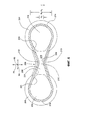
[0034] На фиг. 3 показан вид со стороны конца выходных отверстий многоканального выпускного распределительного устройства, показанного на фиг. 1.[0034] FIG. 3 shows a side view of the end of the outlet openings of the multi-channel outlet switchgear shown in FIG. one.
[0035] На фиг. 4 показан вид сверху многоканального выпускного распределительного устройства, показанного на фиг. 1.[0035] FIG. 4 shows a top view of the multi-channel exhaust switchgear shown in FIG. one.
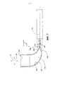
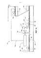
[0036] На фиг. 5 показан вид сбоку многоканального выпускного распределительного устройства, показанного на фиг. 1.[0036] FIG. 5 is a side view of the multi-channel exhaust switchgear shown in FIG. one.
[0037] На фиг. 6 показан разрез многоканального выпускного распределительного устройства, показанного на фиг. 1, по линии VI-VI, показанной на фиг. 4.[0037] FIG. 6 is a sectional view of the multi-channel exhaust switchgear shown in FIG. 1 along line VI-VI shown in FIG. four.
[0038] На фиг. 7 показан разрез многоканального выпускного распределительного устройства, показанного на фиг. 1, по линии VII-VII, показанной на фиг. 4.[0038] FIG. 7 is a sectional view of the multi-channel exhaust switchgear shown in FIG. 1 along line VII-VII shown in FIG. four.
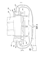
[0039] На фиг. 8 показан вид сбоку многоканального выпускного распределительного устройства, показанного на фиг. 1, расположенного в сжимающем устройстве согласно одному варианту реализации, выполненном в соответствии с принципами настоящего изобретения.[0039] FIG. 8 is a side view of the multi-channel exhaust switchgear shown in FIG. 1 located in a compression device according to one embodiment, made in accordance with the principles of the present invention.
[0040] На фиг. 9 показан вид со стороны входного конца многоканального выпускного распределительного устройства, показанного на фиг. 1, и сжимающего устройства, показанного на фиг. 8.[0040] FIG. 9 is a side view of the input end of the multi-channel exhaust switchgear shown in FIG. 1 and the compression device shown in FIG. 8.
[0041] На фиг. 10 показан вид со стороны выходных отверстий многоканального выпускного распределительного устройства, показанного на фиг. 3, и сжимающего устройства, показанного на фиг. 8.[0041] FIG. 10 is a side view of the outlet openings of the multi-channel exhaust switchgear shown in FIG. 3 and the compression device shown in FIG. 8.
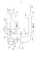
[0042] На фиг. 11 показана схема варианта реализации смешивающего и распределяющего вяжущую суспензию узла, содержащего многоканальное выпускное распределительное устройство, выполненное в соответствии с принципами настоящего изобретения.[0042] FIG. 11 is a schematic diagram of an embodiment of a mixing and dispensing binder suspension assembly comprising a multi-channel outlet dispenser made in accordance with the principles of the present invention.
[0043] На фиг. 12 показана схема варианта реализации загрузочной части производственной линии для изготовления гипсовой стеновой плиты, содержащей варианты реализации многоканального распределительного устройства, выполненного в соответствии с принципами настоящего изобретения.[0043] FIG. 12 is a diagram of an embodiment of a loading portion of a production line for manufacturing a gypsum wall plate containing embodiments of a multi-channel switchgear made in accordance with the principles of the present invention.
ОСУЩЕСТВЛЕНИЕ ИЗОБРЕТЕНИЯDETAILED DESCRIPTION OF THE INVENTION
[0044] В настоящем описании представлены различные варианты реализации смешивающего и распределяющего вяжущую суспензию узла, который может быть использован при изготовлении продуктов, включая вяжущие продукты, такие, например, как гипсовая стеновая плита. Варианты реализации смешивающего и распределяющего вяжущую суспензию узла, построенного в соответствии с принципами настоящего изобретения, могут быть использованы в процессе изготовления и могут содержать многоканальное выпускное распределительное устройство в выпускном трубопроводе, соединенном со смесителем, для эффективного разделения одиночного потока суспензии, такой как водная вспененная гипсовая суспензия, содержащая воздух и жидкие фазы, например, путем введения в делитель потока из смесителя таким образом, что по меньшей мере два независимых потока многофазной суспензии выходят из многоканального выпускного распределительного устройства.[0044] In the present description, various embodiments of a mixing and dispersing binder suspension assembly that can be used in the manufacture of products, including cementitious products, such as, for example, a gypsum wallboard, are presented. Embodiments of a mixing and distributing binder slurry assembly constructed in accordance with the principles of the present invention can be used in the manufacturing process and may include a multi-channel exhaust switchgear in the exhaust pipe connected to the mixer to efficiently separate a single slurry stream, such as aqueous foamed gypsum a suspension containing air and liquid phases, for example, by introducing into the divider the flow from the mixer in such a way that at least at least two independent streams of the multiphase suspension exit the multi-channel outlet switchgear.
[0045] Варианты реализации смешивающего и распределяющего вяжущую суспензию узла, построенного в соответствии с принципами настоящего изобретения, могут быть использованы для смешивания и распределения суспензии (например, водной кальцинированной гипсовой суспензии) на продвигающееся полотно (например, бумагу или пленку), перемещаемое транспортером во время процесса изготовления непрерывной плиты (например, стеновой плиты). В одном аспекте многоканальное выпускное распределительное устройство, построенное в соответствии с принципами настоящего изобретения, может быть использовано в традиционном процессе изготовления гипсовой сухой штукатурки в качестве выпускного трубопровода или его элемента, соединенного со смесителем, выполненным с возможностью смешивания кальцинированного гипса и воды для формирования водной кальцинированной гипсовой суспензии.[0045] Embodiments of a mixing and dispersing binder suspension assembly constructed in accordance with the principles of the present invention can be used to mix and distribute the suspension (eg, aqueous calcined gypsum slurry) onto a moving web (eg paper or film) transported by a conveyor into the time of the manufacturing process of a continuous slab (for example, a wall slab). In one aspect, a multi-channel exhaust dispenser constructed in accordance with the principles of the present invention can be used in a conventional dry gypsum plaster manufacturing process as an exhaust pipe or component connected to a mixer configured to mix calcined gypsum and water to form an aqueous calcined gypsum slurry.
[0046] Смешивающий и распределяющий вяжущую суспензию узел согласно настоящему изобретению может быть использован для формирования вяжущего продукта любого типа, например, такого как плита. Согласно некоторым вариантам реализации может быть сформирована гипсовая плита, такая как, например, гипсовая сухая штукатурка, плита из портландцемента или акустическая панель.[0046] The kneading and dispensing binder assembly of the present invention can be used to form any type of binder product, such as for example a slab. In some embodiments, a gypsum board may be formed, such as, for example, gypsum dry plaster, Portland cement board or an acoustic panel.
[0047] Вяжущая суспензия может быть любой известной вяжущей суспензией, например любой вяжущей суспензией, обычно используемой для изготовления гипсовой стеновой плиты, акустических панелей, включая, например, акустические панели, описанные в публикации патентной заявки США №2004/0231916, или портландцементной плиты. Также, вяжущая суспензия дополнительно может содержать любые добавки, используемые для изготовления плит из вяжущих продуктов. Такие добавки могут быть структурными добавками, включая минеральную вату, непрерывные или рубленные стеклянные волокна (также называемые стекловолокном), перлит, глину, вермикулит, углекислый кальций, полиэфир и бумажное волокно, а также химические добавки, такие как вспенивающие реагенты, заполнители, ускорители, сахар, усиливающие реагенты, такие как фосфаты, фосфонаты, бораты и т.п., ингибиторы, связующие вещества (например, крахмал и латекс), красители, фунгициды, биоциды, гидрофобный реагент, такой как материал на силиконовой основе (например, силан, силоксан или матрица на основе кремнийорганической смолы), и т.п., Примеры использования некоторых из указанных и других добавок описаны, например, в патентах США №№6,342,284; 6,632,550; 6,800,131; 5,643,510; 5,714,001; 6,774,146; и публикациях патентных заявок США №№2004/0231916; 2002/0045074; 2005/0019618; 2006/0035112; и 2007/0022913.[0047] The cementitious slurry may be any known cementitious slurry, for example any cementitious slurry commonly used to make gypsum wallboard, acoustic panels, including, for example, acoustic panels described in US Patent Application Publication No. 2004/0231916, or Portland Cement Board. Also, the binder suspension may additionally contain any additives used for the manufacture of slabs from binder products. Such additives can be structural additives, including mineral wool, continuous or chopped glass fibers (also called fiberglass), perlite, clay, vermiculite, calcium carbonate, polyester and paper fiber, as well as chemical additives such as foaming agents, fillers, accelerators, sugar, reinforcing agents such as phosphates, phosphonates, borates and the like, inhibitors, binders (e.g. starch and latex), dyes, fungicides, biocides, a hydrophobic reagent such as a silicone-based material (n example, silane, siloxane, or silicone-based matrix resin), etc. Examples of some of these and other additives are described, e.g., in U.S. Pat №№6,342,284; 6,632,550; 6,800,131; 5,643,510; 5,714,001; 6,774,146; and US Patent Publication Nos. 2004/0231916; 2002/0045074; 2005/0019618; 2006/0035112; and 2007/0022913.
[0048] Неограничивающие примеры вяжущих материалов включают портландцемент, магнезиальный цемент, шлакоцемент, цемент с добавкой зольной пыли, алюминиево-кальциевый цемент, растворимый в воде ангидрит сульфата кальция, α-гемигидрат сульфата кальция, β-гемигидрат сульфата кальция, природный, синтетический или химически модифицированный гемигидрат сульфата кальция, дигидрат сульфата кальция ("гипс", "схватившийся гипс" или "гидратированный гипс") и их смеси. В одном аспекте настоящего изобретения вяжущий материал в случае необходимости содержит кальцинированный гипс, такой как в форме альфа-гемигидрата сульфата кальция, бета-гем и гидрата сульфата кальция и/или ангидрита сульфата кальция. Согласно некоторым вариантам реализации кальцинированный гипс может быть волокнистым и согласно некоторым вариантам реализации неволокнистым. Кальцинированный гипс может содержать по меньшей мере примерно 50% бета-гемигидрата сульфата кальция. Согласно другим вариантам реализации кальцинированный гипс может содержать по меньшей мере примерно 86% бета-гемигидрата сульфата кальция. Весовое соотношение воды с кальцинированным гипсом может быть любым подходящим соотношением, однако, специалисту понятно, что пониженные отношения могут быть более эффективными, поскольку во время изготовления должно быть удалено минимальное количество избыточной воды для экономии таким образом энергии. Согласно некоторым вариантам реализации вяжущая суспензия может быть подготовлена путем объединения воды и кальцинированного гипса с соотношением в диапазоне отношений от примерно 1:6 по весу соответственно до примерно 1:1, таким, как, например, 2:3, для изготовления плиты в зависимости от продуктов.[0048] Non-limiting examples of binders include Portland cement, magnesia cement, slag cement, fly ash cement, aluminum-calcium cement, water soluble calcium sulfate anhydrite, calcium sulfate α-hemihydrate, calcium sulfate β-hemihydrate, natural, synthetic or chemically modified calcium sulfate hemihydrate, calcium sulfate dihydrate (“gypsum”, “set gypsum” or “hydrated gypsum”) and mixtures thereof. In one aspect of the present invention, the binder optionally contains calcined gypsum, such as in the form of calcium sulfate alpha hemihydrate, beta heme and calcium sulfate hydrate and / or calcium sulfate anhydrite. In some embodiments, the calcined gypsum may be fibrous and, in some embodiments, non-fibrous. Calcined gypsum may contain at least about 50% beta calcium sulfate hemihydrate. In other embodiments, the calcined gypsum may contain at least about 86% beta calcium sulfate hemihydrate. The weight ratio of water to gypsum gypsum can be any suitable ratio, however, one skilled in the art will appreciate that reduced ratios can be more effective since the minimum amount of excess water must be removed during manufacture to save energy in this way. In some embodiments, a binder suspension can be prepared by combining water and calcined gypsum with a ratio in the range of ratios from about 1: 6 by weight, respectively, to about 1: 1, such as, for example, 2: 3, to make a board depending on products.
[0049] На фиг. 1-7 показан вариант реализации многоканального выпускного распределительного устройства 200, выполненного в соответствии с принципами настоящего изобретения. Согласно одному варианту реализации многоканальное выпускное распределительное устройство, выполненное в соответствии с принципами настоящего изобретения, предпочтительно может быть сконфигурировано в качестве усовершенствованного компонента, например, в существующей системе для изготовления стеновой плиты. Многоканальное выпускное распределительное устройство 200 может сообщаться со смесителем 102, например, как показано на фиг. 11 и 12, для доставки от него разделенных потоков суспензии. Согласно некоторым вариантам реализации многоканальное выпускное распределительное устройство содержит концевую часть выпускного трубопровода, который сообщается со смесителем.[0049] FIG. 1-7, an embodiment of a
[0050] Многоканальное выпускное распределительное устройство 200 может быть изготовлено из любого подходящего материала, такого как гибкий материал, включая полихлорвинил (поливинилхлорид), уретан или любой другой подходящий упругий гибкий материал. Согласно другим вариантам реализации многоканальное выпускное распределительное устройство 200 может быть изготовлено из других материалов, таких как по существу жесткий материал (например, алюминий, нержавеющая сталь, и т.п.).[0050] The
[0051] Многоканальное выпускное распределительное устройство 200 содержит входной трубопровод 202 и первый и второй выходные трубопроводы 204, 206, разделенные соединительной частью 210. Входной трубопровод 202 может быть выполнен с возможностью приема основного потока суспензии от смесителя. Пара выходных трубопроводов 204, 206 являются по существу цилиндрическими в показанном на чертеже варианте реализации, и каждый из них сообщается с входным трубопроводом 202. Выходные трубопроводы 204, 206 могут быть выполнены с возможностью выпуска двух отдельных выходных потоков суспензии из многоканального выпускного распределительного устройства 200.[0051] The
[0052] Несмотря на то что показанный на чертеже вариант реализации выпускного распределительного устройства 200 содержит два выходных трубопровода или "канала" 204, 206, следует понимать, что согласно другим вариантам реализации выпускное распределительное устройство согласно принципам настоящего изобретения может иметь больше двух выходных трубопроводов. В вариантах реализации, содержащих больше двух каналов, соединительная часть и/или профилированная часть, описанная в настоящей заявке, может быть установлена между каждой парой смежных каналов.[0052] Although the embodiment of the
[0053] Как показано на фиг. 1, входной трубопровод 202 содержит входную часть 221, переходную часть 223 и пяточную часть 225, расположенную между ними. Входная часть 221 имеет входной конец 203, образующий входное отверстие 207. Входная часть 221 расположена вдоль оси 75 входа основного потока, проходящей между входным концом 203 и пяточной частью 225 (также показано на фиг. 5). Входное отверстие 207 входного конца 203 может быть выполнено с возможностью сообщаться со смесителем и принимать от него основной поток суспензии.[0053] As shown in FIG. 1, the
[0054] Переходная часть 223 имеет соединительный конец 205. Переходная часть 223 расположена вдоль оси 85 выпуска основного потока, проходящей между пяточной частью 225 и соединительным концом 205 (также показаны на фиг. 5).[0054] The
[0055] Как показано на фиг. 5, входная часть 221 расположена под углом θ подачи относительно переходной части 223 и первого и второго выходных трубопроводов 204, 206. Угол θ подачи согласно некоторым вариантам реализации может находиться в диапазоне от примерно 45° до примерно 170°, согласно другим вариантам реализации от примерно 60° до примерно 120° и согласно другим вариантам реализации от примерно 70° до примерно 110°. Показанная на чертеже входная часть 221 по существу перпендикулярна переходной части 223, а также первому и второму выходным трубопроводам 204, 206.[0055] As shown in FIG. 5, the
[0056] Как показано на фиг. 6, соединительный конец 205 образует первое и второе соединительные отверстия 209, 211. Первое соединительное отверстие 209 расположено на расстоянии от второго соединительного отверстия 211. Первое и второе соединительные отверстия 209, 211 выполнены с возможностью разделения основного потока водной вяжущей суспензии на первый выпускной поток водной суспензии и второй выпускной поток водной суспензии.[0056] As shown in FIG. 6, the connecting
[0057] Как показано на фиг. 7, пяточная часть 225 имеет поверхность 241, выполненную с возможностью направления потока суспензии, перемещающейся от входного отверстия 207 вдоль оси 75 входа основного потока через пяточную часть 225 к переходной части 223 вдоль оси 85 выпуска основного потока. Пяточная часть 225 может быть выполнена с возможностью перенаправления основного потока суспензии от оси 75 входа основного потока к оси 85 выпуска основного потока путем изменения направляющего угла α. Согласно некоторым вариантам реализации изменение направляющего угла α может находиться в диапазоне от примерно 10° до примерно 135°, согласно другим вариантам реализации от примерно 60° до примерно 120° и согласно другим вариантам реализации от примерно 70° до примерно 110°.[0057] As shown in FIG. 7, the
[0058] Как показано на фиг. 3, первый выходной трубопровод 204 сообщается с первым соединительным отверстием 209 входного трубопровода 202. Первый выходной трубопровод 204 содержит выпускной конец 215, образующий первое выпускное отверстие 217. Первый выходной трубопровод 204 выполнен с возможностью приема первого выпускного потока водной суспензии из входного трубопровода 202 и распределения первого выпускного потока из первого выпускного отверстия 217.[0058] As shown in FIG. 3, a
[0059] Второй выходной трубопровод 206 сообщается со вторым соединительным отверстием 211 входного трубопровода 202. Второй выходной трубопровод 206 содержит выпускной конец 225, образующий второе выпускное отверстие 227. Второй выходной трубопровод 206 выполнен с возможностью приема второго выпускного потока водной суспензии из входного трубопровода 202 и распределения второго выпускного потока из второго выпускного конца 225.[0059] The
[0060] Как показано на фиг. 1 и 2, соединительная часть 210 расположена в соединительном конце 205 входного трубопровода 202. Как показано на фиг. 6, соединительная часть 210 расположена между первым соединительным отверстием 209 и вторым соединительным отверстием 211. Соединительная часть 210 содержит по существу плоскую стеновую область 219 (также показанную на фиг. 7). Как показано на фиг. 7, стеновая область 219 по существу перпендикулярна оси 85 выпуска основного потока.[0060] As shown in FIG. 1 and 2, the connecting
[0061] Как показано на фиг. 3 и 4, каждое из первого выпускного отверстия 217 первого выходного трубопровода 204 и второго выпускного отверстия 227 второго выходного трубопровода 206 может иметь площадь поперечного сечения меньше или примерно равную площади поперечного сечения входного отверстия 207 входного трубопровода 202. Согласно некоторым вариантам реализации каждая из площади поперечного сечения первого выпускного отверстия 217 первого выходного трубопровода 204 и площади поперечного сечения второго выпускного отверстия 227 второго выходного трубопровода 206 меньше, чем примерно 85% от площади поперечного сечения входного отверстия 207 входного трубопровода 202. Согласно некоторым вариантам реализации площадь поперечного сечения первого выпускного отверстия 217 первого выходного трубопровода 204 по существу равна площади поперечного сечения второго выпускного отверстия 227 второго выходного трубопровода 206.[0061] As shown in FIG. 3 and 4, each of the
[0062] В показанном на чертеже варианте реализации внутренний диаметр ∅1 входного отверстия 207 входного трубопровода 202 больше, чем внутренние диаметры ∅2, ∅3 первого выпускного отверстия 217 первого выходного трубопровода 204 и второго выпускного отверстия 227 второго выходного трубопровода 206 соответственно. В показанном на чертеже варианте реализации соответствующие внутренние диаметры ∅2, ∅3 первого выпускного отверстия 217 первого выходного трубопровода 204 и второго выпускного отверстия 227 второго выходного трубопровода 206 по существу одинаковы.[0062] In the embodiment shown, the inner diameter ∅ 1 of the
[0063] Внутренние диаметры ∅1, ∅2, ∅3 (и, таким образом, площади поперечных сечений) входного отверстия 207 и первого и второго выпускных отверстий 217, 227 могут быть изменены в зависимости от необходимой средней скорости потока. Более высокая средняя скорость потока может уменьшить риск наращивания отложений схватившегося материала из-за затвердевания суспензии, осевшей в выпускном распределительном устройстве 200. Внутренний диаметр ∅2, ∅3 первого и второго выпускных отверстий 217, 227 может быть меньше, чем внутренний диаметр ∅1 входного отверстия 207, для поддерживания относительно высокой скорости потока по всему многоканальному выпускному распределительному устройству 200. Если внутренние диаметры ∅2, ∅3 первого и второго выпускных отверстий 217, 227 будут по существу равны внутреннему диаметру ∅1 входного отверстия 207, средняя скорость потока суспензии через выходные трубопроводы 204, 206 будет уменьшена примерно на 50%, если объемный расход через входное отверстие и оба выходных отверстия будет по существу одинаковым. Однако, если внутренние диаметры выходных трубопроводов 204, 206 меньше, чем внутренний диаметр входного трубопровода, скорость потока в выходных трубопроводах 204, 206 может быть поддержана без изменений или по меньшей мере уменьшена в меньшей степени, чем если бы выпускные трубопроводы 204, 206 и входной трубопровод 202 имели по существу равные внутренние диаметры ∅1, ∅2, ∅3.[0063] The inner diameters ∅ 1 , ∅ 2 , ∅ 3 (and thus the cross-sectional areas) of the
[0064] Многоканальное выпускное распределительное устройство 200 также содержит центральную профилированную часть 208. Как показано на фиг. 6 и 7, входной трубопровод 202 образует входной канал 231 проходящий между входным отверстием 207 и первым и вторым соединительными отверстиями 209, 211. Входной трубопровод 202 содержит профилированную часть 208, которая образует сужение 235 во входном канале 231 рядом с соединительной частью 210.[0064] The multi-channel
[0065] Профилированная часть 208 содержит верхнюю выпуклую область 212 и противоположную ей нижнюю выпуклую область 213. Верхняя и нижняя выпуклые области 212, 213 обращены друг к другу во входном канале 231 с образованием сужения 235 между ними.[0065] The profiled
[0066] Как показано на фиг. 6, профилированная часть 208 образует первый и второй направляющие каналы 218, 220. Сужение 235 проходит в боковом направлении между первым и вторым направляющими каналами 218, 220 вдоль поперечной оси 95, по существу перпендикулярной оси 85 выпуска основного потока. Первый и второй направляющие каналы 218, 220 проходят в боковом направлении наружу относительно верхней и нижней выпуклых областей 212, 213 соответственно. Каждый из первого и второго направляющих каналов 218, 220 имеет площадь поперечного сечения, которая больше, чем площадь поперечного сечения сужения 235. Первый и второй направляющие каналы 218, 220 по существу выровнены с первым и вторым соединительными отверстиями 209, 211, соответственно.[0066] As shown in FIG. 6, the profiled
[0067] Сужение 235 имеет максимальную высоту H1 вдоль оси высоты, которая совпадает с осью 75 входа основного потока согласно данному варианту реализации. Ось 75 высоты перпендикулярна оси 85 выпуска основного потока и поперечной оси 95. Каждый из первого и второго направляющих каналов 218, 220 имеет максимальную высоту H2, Н3 вдоль оси 75 высоты, которая больше, чем максимальная высота H1 сужения 235. В показанном на чертеже варианте реализации первый и второй направляющие каналы 218, 220 имеют по существу одинаковую максимальную высоту Н2, Н3 вдоль оси 75 высоты.[0067] The
[0068] Профилированная часть 208 содержит верхнее углубление 212 в верхней части многоканального выпускного распределительного устройства 200 и нижнее углубление 213 в нижней части многоканального выпускного распределительного устройства 200, которые способствуют смещению потока в направлении к наружным боковым краям 214, 216 многоканального выпускного распределительного устройства для уменьшения риска наращивания отложений суспензии в соединительной части 210. Как показано на чертежах, форма центральной профилированной части 208 определяет большие каналы 218, 220, расположенные вплотную к ее соответствующим наружным краям 214, 216. Углубления 212, 213 в центральной части 208 образуют сужение 235, которое имеет уменьшенную площадь поперечного сечения по сравнению с площадью поперечного сечения в области наружных краев 214, 216 и уменьшенную высоту Н2, Н3 по сравнению с расположенными рядом наружными краями Н2, Н3. В результате, суспензия, протекающая вдоль оси 85 выпуска основного потока в направлении к соединительной части 210, встречает уменьшенное сопротивление потоку в направляющих каналах 218, 220, расположенных у наружных краев 214, 216. Таким образом, поток направлен в большие каналы 218, 220 рядом с наружными краями 214, 216 многоканального выпускного распределительного устройства 200 и дальше от центральной части 208 и соединительной части 210.[0068] The profiled
[0069] Соединительная часть 210 расположена между указанными двумя выходными трубопроводами 204, 206. Соединительная часть 210 состоит из плоской стенки 219, которая по существу перпендикулярна оси 85 выпуска основного потока, вдоль которой суспензия протекает при входе во входное отверстие 207 входного трубопровода 202. Размер плоской стенки 219 выбран таким образом, чтобы препятствовать обертыванию волокон и других добавок, присутствующих в вяжущей суспензии, вокруг соединительной части 210 и наращиванию отложений в данном месте (процесс также называется "закупориванием"). Плоская стенка 219 может быть выполнена с возможностью препятствовать прилипанию суспензии к соединительной части 210, наращиванию отложений и в конечном счете отрыву с образованием кусков. В зависимости от скорости транспортера и объемов, протекающих через многоканальное выпускное распределительное устройство 200 и каналы 204, 206 распределительного устройства, конструкция соединительной части 210 и центральной профилированной часть 208 может быть изменена для достижения необходимых результатов.[0069] The connecting
[0070] Соединительная часть 210 может быть выполнена с возможностью препятствования наращиванию отложений суспензии в области непосредственно выше по потоку соединительной части 210. Однако, если указанное наращивание отложений действительно имеет место, оно может нарушить поток суспензии, в результате чего разделение потока суспензии может стать неровным и/или ступенчатым. Захваченные наросты отложений суспензии могут затвердеть и схватиться и в конечном счете могут оторваться и образовать трудно проходимые куски в потоке суспензии, что может вызвать проблемы и прерывания процесса, такие как отрывы бумаги в станции обработки давлением.[0070] The connecting
[0071] На фиг. 8-10 показаны вариант реализации сжимающего устройства или автоматического сжимающего устройства 300 для сжимающего многоканального выпускного распределительного устройства 200 в регулируемом и обычном временных интервалах, выполненного с возможностью препятствования наращиванию отложений суспензии в многоканальном выпускном распределительном устройстве. Сжимающее устройство 300 устраняет потенциальную проблему очистки многоканального выпускного распределительного устройства 200 при разделении посредством указанного устройства основного потока входящей вяжущей суспензии на два выходных потока. Сжимающее устройство 300 сжимает центральную часть 208 многоканального выпускного распределительного устройства 200 для уменьшения наращивания отложений схватившейся суспензии в соединительной части 210.[0071] FIG. 8-10 show an embodiment of a compression device or
[0072] Сжимающее устройство 300 содержит первый и второй сжимающие элементы 302, 304, расположенные на расстоянии друг от друга. Соединительная часть 210 многоканального выпускного распределительного устройства 200 расположена между первым и вторым сжимающими элементами 302, 304. По меньшей мере один из первого и второго сжимающих элементов 302, 304 выполнен с возможностью перемещения в диапазоне перемещения относительно другого сжимающего элемента 304 вдоль сжимающей оси 75, которая по существу перпендикулярна оси 85 выпуска основного потока, между нормальным положением и сжатым положением (как показано на втором сжимающем элементе 304 пунктирными линиями на фиг. 9). В сжатом положении часть по меньшей мере одного из входного трубопровода 202 и первого и второго выходных трубопроводов 204, 206 рядом с соединительной частью 210 сжата относительно нормального положения. Согласно некоторым вариантам реализации соединительная часть 210 сжата, когда сжимающие элементы 302, 304 находятся в сжатом положении относительно нормального положения.[0072] The
[0073] Каждый из сжимающих элементов 302, 304 содержит по существу плоскую сжимающую поверхность 303, 305. Сжимающие поверхности 303, 305 по существу параллельны друг другу и оси 75 выпуска основного потока.[0073] Each of the
[0074] Как показано на фиг. 9, сжимающее устройство 300 содержит по меньшей мере один приводной механизм 306, выполненный с возможностью выборочного перемещения первого сжимающего элемента 302 относительно второго сжимающего элемента 304. В показанном на чертеже варианте реализации второй сжимающий элемент 304, который расположен ниже многоканального выпускного распределительного устройства 200, выполнен с возможностью перемещения, а первый сжимающий элемент 302 неподвижен. Согласно другим вариантам реализации возможны другие устройства для перемещения.[0074] As shown in FIG. 9, the
[0075] Сжимающее устройство 300 может содержать контроллер 320, выполненный с возможностью управления каждым приводным механизмом 306 таким образом, что приводной механизм 306 периодически активируется с заданной частотой для периодического сжатия соединительной части. Контроллер 320 может быть выполнен с возможностью управления каждым приводным механизмом 306 таким образом, что приводной механизм 306 активирован для перемещения первого и второго сжимающих элементов 302, 304 в направлении друг к другу на заданную длину L1 хода (как показано на фиг. 10).[0075] The
[0076] Как показано на фиг. 8-10, сжимающее устройство 300 расположено вплотную к соединительной части 210 многоканального выпускного распределительного устройства 200. Первый и второй сжимающие элементы выполнены в форме верхней пластины 302 и нижней пластины 304. Верхняя пластина 302 расположена на верхней части многоканального выпускного распределительного устройства 200, а нижняя пластина 304 расположена ниже многоканального выпускного распределительного устройства 200. Показанное на фиг. 9 сжимающее устройство 300 содержит пару приводных механизмов 306, выполненных в форме пневматического цилиндра 308 с выполненным с возможностью возвратно-поступательного перемещения поршнем 310. Каждый приводной механизм 306 прикреплен к верхней пластине 302 и нижней пластине 304 таким образом, что при активировании приводного механизма поршень 310 втягивается, и нижняя пластина 304 перемещается в направлении к верхней пластине 302 на заданную длину L1 хода вдоль оси 75 высоты, которая по существу перпендикулярна оси 75 основного потока. Пара пневматических линий 312 соединена с пневматической камерой 308 каждого приводного механизма 306 и с источником сжатого воздуха 322. Контроллер 320 выполнен с возможностью выборочного управления источником сжатого воздуха 322, например, посредством подходящих электрически управляемых клапанов, например, для выборочного манипулирования приводными механизмами 306 для втягивания поршней 310 с целью сжатия сжимающего устройства и выдвигания поршней для возвращения пластин 302, 304 в нормальное положение. Приводным механизмом 306 можно управлять автоматически или с выборочным перемещением пластин 302, 304 вместе относительно друг друга для приложения сжимающего усилия к делителю 200 потока в снабженной выемкой центральной части 208 и соединительной части 210. Перемещение верхней и нижней пластин 302, 304 в направлении друг к другу увеличивает сжимающее усилие, которое может вызвать изгибание многоканального выпускного распределительного устройства 200 во внутреннем направлении в соединительной части 210 для препятствования наращиванию отложений суспензии.[0076] As shown in FIG. 8-10, the
[0077] Когда сжимающее устройство 300 сжимает многоканальное выпускное распределительное устройство 200, сжимающее действие прикладывает сжимающее усилие к указанному распределительному устройству, которое в ответ изгибается внутрь. Указанная сила препятствует наращиванию отложений твердых частиц, которые могут нарушить поток суспензии, протекающий по выходным трубопроводам 204, 206 многоканального выпускного распределительного устройства 200. Согласно некоторым вариантам реализации сжимающее устройство 300 сконструировано с возможностью автоматического пульсирования под управлением программируемого контроллера, функционально связанного с приводными механизмами 306. Сжимающее устройство 300 может быть выполнено таким образом, что оно активируется с изменяющимися длинами хода и частотами, которые могут быть выбраны в зависимости от производственных условий. Сжимающее устройство 300 также может способствовать поддерживанию внутренней геометрии многоканального выпускного распределительного устройства 200 и препятствовать нежелательному искажению его формы, что может способствовать поддерживанию надлежащей скорости и реологических характеристик суспензии, протекающей через многоканальное выпускное распределительное устройство 200.[0077] When the
[0078] На фиг. 11 и 12 показан вариант реализации смешивающего и распределяющего вяжущую суспензию узла 100, который содержит смеситель 102 вяжущей суспензии, который сообщается с многоканальным выпускным распределительным устройством 200, выполненным в соответствии с принципами настоящего изобретения. Смеситель 102 вяжущей суспензии выполнен с возможностью смешивания воды и вяжущего материала для формирования водной вяжущей суспензии. Вода и вяжущий материал могут быть поданы в смеситель 102 через одно или большее количество входных отверстий, как известно в уровне техники. В смешивающем и распределяющем суспензию узле 100 может быть использован любой подходящий смеситель (например, лопастной смеситель).[0078] FIG. 11 and 12 show an embodiment of a mixing and dispensing
[0079] Многоканальное выпускное распределительное устройство 200, показанное на фиг. 11, выполнено с возможностью разделения входящего основного потока суспензии из смесителя 102 на два по существу одинаковых выпускных потока. Многоканальное выпускное распределительное устройство 200 содержит входной трубопровод 202, выполненный с возможностью приема основного потока суспензии из смесителя 102, и пару выходных трубопроводов 204, 206, каждый из которых сообщается с входным трубопроводом 202, и распределения двух выходных потоков суспензии из многоканального выпускного распределительного устройства 200.[0079] The multi-channel
[0080] Выпускной подающий трубопровод 104 сообщается со смесителем 102 и содержит многоканальное выпускное распределительное устройство 200. Подающий трубопровод 104 может быть изготовлен из любого подходящего материала и может иметь различные формы. Согласно некоторым вариантам реализации подающий трубопровод 104 может содержать гибкий трубопровод.[0080] The
[0081] Подающий трубопровод 108 для водной пены может сообщаться по меньшей мере с одним из смесителя 102 и подающего трубопровода 104. Водная пена от источника может быть добавлена к составным материалам посредством подающего трубопровода 108 для пены в любом подходящем месте ниже по потоку смесителя 102 и/или непосредственно в смесителе 102 для формирования вспененной вяжущей суспензии, которую подают в многоканальное выпускное распределительное устройство 200. В показанном на чертеже варианте реализации подающий трубопровод 108 для пены расположен ниже по потоку смесителя 112. В показанном на чертеже варианте реализации подающий трубопровод водной 108 для пены имеет конструкцию коллекторного типа для подачи пены в инжекционное кольцо или блок, связанный с подающим трубопроводом 104, например, как описано в патенте США №6,874,930.[0081] The water
[0082] Согласно другим вариантам реализации могут быть использованы один или большее количество вторичных подающих трубопроводов для пены, которые сообщаются со смесителем 102. Согласно другим вариантам реализации подающий трубопровод или трубопроводы для водной пены могут сообщаться только со смесителем 102. Специалисту понятно, что средством для введения водной пены в вяжущую суспензию в смешивающем и распределяющем вяжущую суспензию узле 100, включая его относительное место на узле, может быть изменено и/или оптимизировано для обеспечения однородной дисперсии водной пены в вяжущей суспензии для изготовления плиты, пригодной для ее назначения.[0082] In other embodiments, one or more secondary foam supply lines may be used that communicate with the
[0083] Может быть использован любой подходящий пенообразователь. Предпочтительно водная пена изготавливается непрерывным способом, согласно которому поток смеси пенообразователя и воды направляют в пеногенератор, и поток результирующей водной пены выпускают из пеногенератора, вводят в вяжущую суспензию и смешивают с ней. Некоторые примеры подходящих пенообразователей, например, описаны в патентах США №№5,683,635 и 5,643,510.[0083] Any suitable blowing agent may be used. Preferably, the water foam is produced in a continuous way, according to which the flow of the mixture of the foaming agent and water is directed to the foam generator, and the flow of the resulting water foam is discharged from the foam generator, introduced into the binder suspension and mixed with it. Some examples of suitable blowing agents, for example, are described in US Pat. Nos. 5,683,635 and 5,643,510.
[0084] После схватывания и высыхания вспененной вяжущей суспензии пена, рассеянная в суспензии, образует в ней воздушные полости, которые способствуют уменьшению общей плотности стеновой плиты. Количество пены и/или количество воздуха в пене может быть изменено для регулирования плотности сухой плиты таким образом, что результирующий продукт стеновой плиты находится в пределах необходимого весового диапазона.[0084] After the foamed binder suspension has set and dried, the foam dispersed in the suspension forms air cavities in it, which contribute to a decrease in the overall density of the wall plate. The amount of foam and / or the amount of air in the foam can be changed to control the density of the dry plate so that the resulting product of the wall plate is within the required weight range.
[0085] Один или большее количество изменяющих поток элементов 106 могут быть связаны с подающим трубопроводом 104 и выполнены с возможностью управления основным потоком водной вяжущей суспензии из смесителя 102. Изменяющий поток элемент или элементы 106 могут быть использованы для управления рабочей характеристикой основного потока водной вяжущей суспензии. В показанном на фиг. 11 и 12 варианте реализации изменяющий поток элемент или элементы 106 связаны с выпускным трубопроводом 104. Примеры подходящих изменяющих поток элементов включают ограничители объема, редукторы давления, дроссельные клапаны, баллоны и т.п., включая, например, описанные в патентах США №№6,494,609; 6,874,930; 7,007,914; и 7,296,919.[0085] One or more flow-modifying
[0086] При использовании, основной поток водной вяжущей суспензии выпускают из смесителя 102 в подающий трубопровод 104, водную пену вводят в основной поток посредством подающего трубопровода 108 для пены, и посредством изменяющего поток элемента или элементов 106 управляют рабочей характеристикой основного потока водной вяжущей суспензии. Основной поток водной вяжущей суспензии направляют во входной трубопровод 202 многоканального выпускного распределительного устройства 200. Основной поток водной вяжущей суспензии из смесителя 102 перенаправляют во входном трубопроводе 202 и разделяют в многоканальном выпускном распределительном устройстве 200 на первый поток подачи водной вяжущей суспензии и второй поток подачи водной вяжущей суспензии, которые выпускают из указанного распределительного устройства через первый и второй выходные трубопроводы 204, 206 соответственно. Многоканальное выпускное распределительное устройство 200 может разделять входящий основной поток вяжущей суспензии из смесителя 102 на два по существу одинаковых потока, которые могут быть выпущены из многоканального выпускного распределительного устройства 200 на продвигающееся полотно из материала покрытия, например, продвигающееся вдоль машинной оси 50.[0086] In use, the main stream of aqueous binder slurry is discharged from the
[0087] Многоканальное выпускное распределительное устройство 200 может действовать для замедления потока суспензии и способствовать распространению суспензии вдоль поперечной оси 60, которая по существу перпендикулярна машинному направлению 50, поперек ширины продвигающегося полотна из материала покрытия. Согласно различным вариантам реализации многоканальное выпускное распределительное устройство 200 может иметь различные конструкции и размеры в зависимости от предполагаемого объема суспензии и скорости линии, транспортирующей плиту. В линиях для изготовления плит, работающие с повышенными скоростями, могут быть использованы многоканальные распределительные устройства для преодоления проблем, связанных с распространением суспензии вдоль оси 60, перпендикулярной машинному направлению, в указанных случаях применения.[0087] The
[0088] На фиг. 12 показан примерный вариант реализации загрузочной части 150 производственной линии для изготовления гипсовой стеновой плиты. Показанная на чертеже загрузочная часть 150 содержит смешивающий и распределяющий вяжущую суспензию узел 100, содержащий многоканальное выпускное распределительное устройство 200, ролик 152 твердого края/лицевой грунтовки, расположенный выше по потоку многоканального выпускного распределительного устройства 200 и поддерживаемый над сеточным столом 154 таким образом, что первое продвигающееся полотно 156 из материала покрытия расположено между ними, ролик 158 обратной грунтовки, расположенный над опорным элементом 160 таким образом, что второе продвигающееся полотно 162 из материала покрытия расположено между ними, и станцию 164 для обработки давлением, выполненную с возможностью формирования заготовки с необходимой толщиной. Ролики 152, 158 для нанесения грунтовки, сеточный стол 154, опорный элемент 160 и станция 164 для обработки давлением могут содержать традиционное оборудование, подходящее для их назначения, как известно в уровне техники. Загрузочная часть 150 может быть оборудована другим известным традиционным оборудованием.[0088] FIG. 12 shows an exemplary embodiment of a
[0089] Вода и кальцинированный гипс могут быть смешаны в смесителе 512 для формирования водной кальцинированной гипсовой суспензии. Согласно некоторым вариантам реализации может быть выполнено непрерывное добавление воды и кальцинированного гипса в смеситель с соотношением воды к кальцинированному гипсу в диапазоне от приблизительно 0,5 до приблизительно 1,3, и согласно другим вариантам реализации приблизительно 0,75 или меньше.[0089] Water and calcined gypsum can be mixed in a mixer 512 to form an aqueous calcined gypsum slurry. In some embodiments, continuous addition of water and calcined gypsum to the mixer can be performed with a ratio of water to calcined gypsum in the range of about 0.5 to about 1.3, and according to other embodiments, about 0.75 or less.
[0090] Продукты гипсовой плиты обычно формируют "лицевой стороной вниз", так что продвигающееся полотно 156 выполняет функцию "лицевой" поверхности плиты после ее монтажа. Поток 166 с лицевой грунтовкой/твердым краем (слоем более плотной водной кальцинированной гипсовой суспензии относительно по меньшей мере одного из первого и второго потоков водной кальцинированной гипсовой суспензии) может быть применен к первому продвигающемуся полотну 156 выше по потоку ролика 152 твердого края/лицевой грунтовки относительно машинного направления 168 для применения слоя грунтовки к первому полотну 156 и формирования твердых краев плиты.[0090] The gypsum board products are typically formed face-down, so that the advancing
[0091] Многоканальное выпускное распределительное устройство 200 может быть использовано для выпуска водной кальцинированной гипсовой суспензии на первое продвигающееся полотно 156. Основной поток 121 водной кальцинированной гипсовой суспензии выпускают из смесителя 102 в выпускной трубопровод 104, содержащий многоканальное выпускное распределительное устройство 200. Основной поток водной кальцинированной гипсовой суспензии, поданный во входной трубопровод 202 многоканального выпускного распределительного устройства 200 и перенаправленный в нижнем направлении во входном трубопроводе 202 на продвигающееся полотно 156 из материала покрытия, перемещающееся в машинном направлении 168 на сеточном столе 154, перенаправляют во входном трубопроводе 202 таким образом, что основной поток водной кальцинированной гипсовой суспензии перемещается по существу вдоль машинного направления 168 и разделяется в нем между первым выходным трубопроводом 204 и вторым выходным трубопроводом 206 для образования первого и второго выпускных потоков 180, 182 соответственно. Первый и второй выпускные потоки 180, 182 водной кальцинированной гипсовой суспензии могут быть выпущены из многоканального выпускного распределительного устройства 200 на первое продвигающееся полотно 156.[0091] A
[0092] Согласно некоторым вариантам реализации каждый из первого выпускного потока 180 водной кальцинированной гипсовой суспензии и второго выпускного потока 182 водной кальцинированной гипсовой суспензии имеет среднюю скорость, которая составляет по меньшей мере примерно 50% от средней скорости основного потока 121 водной кальцинированной гипсовой суспензии, входящей во входной трубопровод 202 из многоканального выпускного распределительного устройства 200. Согласно некоторым вариантам реализации каждый из первого выпускного потока 180 водной кальцинированной гипсовой суспензии и второго выпускного потока 182 водной кальцинированной гипсовой суспензии имеет среднюю скорость, которая составляет по меньшей мере примерно 70% от средней скорости основного потока 121 водной кальцинированной гипсовой суспензии, входящей в многоканальное выпускное распределительное устройство 200. Согласно некоторым вариантам реализации первый и второй выпускные потоки 180, 182 водной кальцинированной гипсовой суспензии могут иметь по меньшей мере одну характеристику потока, которая по существу является одинаковой, такую, например, как средняя скорость.[0092] In some embodiments, each of the first aqueous calcined gypsum
[0093] Поток 166 с лицевой грунтовкой/твердым краем может быть выпущен из смесителя 102 в точке выше по потоку относительно направления перемещения первого продвигающегося полотна 156 в машинном направлении 168, в котором первый и второй потоки 180, 182 водной кальцинированной гипсовой суспензии выпущены из многоканального выпускного распределительного устройства 200 на первое продвигающееся полотно 156. Первый и второй потоки 180, 182 водной кальцинированной гипсовой суспензии могут быть выпущены из распределителя суспензии с уменьшенной средней скоростью для облегчения препятствования "вымыванию" потока 166 с лицевой грунтовкой/твердым краем, нанесенного на первое продвигающееся полотно 156 (т.е., в ситуации, в которой часть уложенного слоя грунтовки смещена со своей позиции на продвигающемся полотне 156 в ответ на воздействие суспензии, нанесенной на него).[0093] The primer / hard-edged
[0094] Поток 184 с обратной грунтовкой (слой более плотной водной кальцинированной гипсовой суспензии относительно по меньшей мере одного из первого и второго потоков 180, 182 водной кальцинированной гипсовой суспензии) может быть применен ко второму продвигающемуся полотну 162. Поток 184 с обратной грунтовкой может быть выпущен из смесителя 102 в месте выше по потоку относительно направления перемещения второго продвигающегося полотна 162 ролика 158 обратной грунтовки. Второе продвигающееся полотно 162 из материала покрытия может быть размещено поверх суспензии, выпущенной из многоканального выпускного распределительного устройства 200 на продвигающееся первое полотно 156, для получения многослойной заготовки стеновой плиты, которую подают в станцию 164 для обработки давлением для формирования заготовки с необходимой толщиной.[0094] The reverse primer stream 184 (a layer of a denser aqueous calcined gypsum slurry relative to at least one of the first and second aqueous calcined gypsum slurry streams 180, 182) can be applied to the second advancing
[0095] В другом аспекте настоящего изобретения многоканальное выпускное распределительное устройство, выполненное в соответствии с принципами настоящего изобретения, может быть использовано в различных процессах изготовления. Например, согласно одному варианту реализации многоканальное выпускное распределительное устройство может быть использовано в способе подготовки гипсового продукта. Многоканальное выпускное распределительное устройство может быть использовано для разделения основного потока водной кальцинированной гипсовой суспензии, выпущенного из смесителя, по меньшей мере на два выпускных потока водной кальцинированной гипсовой суспензии, которые выпускают из многоканального выпускного распределительного устройства.[0095] In another aspect of the present invention, a multi-channel exhaust switchgear configured in accordance with the principles of the present invention can be used in various manufacturing processes. For example, according to one embodiment, a multi-channel exhaust dispenser may be used in a method for preparing a gypsum product. A multi-channel outlet dispenser may be used to separate the main stream of aqueous calcined gypsum slurry discharged from the mixer into at least two outlet streams of an aqueous calcined gypsum slurry that are discharged from the multi-channel outlet dispenser.
[0096] В вариантах реализации способа подготовки вяжущего продукта основной поток водной суспензии может быть выпущен из смесителя. Основной поток суспензии перенаправляют во входном трубопроводе многоканального выпускного распределительного устройства от оси входа основного потока к оси выпуска основного потока путем изменения направляющего угла в пределах диапазона от примерно 10° до примерно 135°. Основной поток водной суспензии перемещают вдоль сужения, расположенного во входном трубопроводе выше по потоку соединительной части, разделяющей первый и второй выходные трубопроводы многоканального выпускного распределительного устройства. Основной поток водной суспензии, продвигающейся вдоль оси выпуска основного потока, разделяют на первый выпускной поток водной суспензии и второй выпускной поток водной суспензии в многоканальном выпускном распределительном устройстве. Первый и второй выпускные потоки выпускают из первого и второго выходных трубопроводов.[0096] In embodiments of the binder preparation process, the main aqueous suspension stream may be discharged from the mixer. The main stream of the suspension is redirected in the inlet pipe of the multi-channel exhaust switchgear from the inlet axis of the main stream to the axis of the main stream outlet by changing the guide angle within the range from about 10 ° to about 135 °. The main stream of the aqueous suspension is moved along the narrowing located in the inlet pipe upstream of the connecting part separating the first and second outlet pipelines of the multi-channel outlet switchgear. The main stream of the aqueous suspension advancing along the axis of discharge of the main stream is divided into a first outlet stream of the aqueous suspension and a second outlet stream of the aqueous suspension in a multi-channel outlet switchgear. The first and second exhaust streams are discharged from the first and second outlet pipelines.
[0097] Согласно некоторым вариантам реализации первый и второй направляющие каналы расположены с обеих сторон указанного сужения. Первый и второй направляющие каналы могут быть по существу соответственно выровнены с первым и вторым соединительными отверстиями, ведущими к первому и второму выходным трубопроводам соответственно.[0097] In some embodiments, the first and second guide channels are located on both sides of said narrowing. The first and second guide channels can be substantially aligned with the first and second connecting holes leading to the first and second outlet pipes, respectively.
[0098] Согласно некоторым вариантам реализации каждый из первого и второго выпускных потоков водной суспензии имеет среднюю скорость, которая составляет по меньшей мере примерно 50% от средней скорости основного потока суспензии, поступающей во входной трубопровод многоканального выпускного распределительного устройства. Согласно некоторым вариантам реализации каждый из первого и второго выпускных потоков водной суспензии имеет среднюю скорость, которая составляет по меньшей мере примерно 75% от средней скорости основного потока водной суспензии, поступающей во входной трубопровод многоканального выпускного распределительного устройства. Согласно некоторым вариантам реализации способ подготовки вяжущего продукта может включать этап, согласно которому выпускают первый и второй выпускные потоки водной суспензии из распределителя суспензии на полотно из материала покрытия, продвигающееся вдоль машинного направления.[0098] According to some embodiments, each of the first and second outlet streams of the aqueous suspension has an average speed that is at least about 50% of the average speed of the main stream of the suspension entering the inlet pipe of the multi-channel outlet distribution device. In some embodiments, each of the first and second outlet streams of the aqueous suspension has an average speed that is at least about 75% of the average speed of the main stream of the aqueous suspension entering the inlet pipe of the multi-channel outlet distribution device. In some embodiments, a method for preparing a binder product may include the step of releasing the first and second exhaust streams of the aqueous suspension from the suspension distributor onto a web of coating material advancing along the machine direction.
[0099] Согласно некоторым вариантам реализации способ подготовки вяжущего продукта может включать этап, на котором сжимают соединительную часть многоканального выпускного распределительного устройства. Соединительная часть может быть расположена между первым выходным трубопроводом и вторым выходным трубопроводом многоканального выпускного распределительного устройства. Согласно некоторым вариантам реализации соединительную часть периодически сжимают с заданной частотой. Согласно некоторым вариантам реализации сжатие соединительной части включает этап, согласно которому перемещают первый и второй сжимающие элементы в направлении друг к другу на заданную длину хода.[0099] According to some embodiments, the method of preparing the binder product may include compressing the connecting portion of the multi-channel outlet dispenser. The connecting part may be located between the first outlet pipe and the second outlet pipe of the multi-channel outlet switchgear. In some embodiments, the connecting portion is periodically compressed at a predetermined frequency. According to some embodiments, the compression of the connecting part includes the step of moving the first and second compressing elements toward each other by a predetermined stroke length.
[00100] Все ссылки, процитированные в настоящей заявке, включены в нее посредством ссылки в той мере, как если бы каждая ссылка была отдельно упомянута как включенная по ссылке в настоящую заявку и была полностью изложена в ней.[00100] All references cited in this application are incorporated by reference to the extent that each link was separately mentioned as being incorporated by reference into the present application and was fully set forth therein.
[00101] Использованные в настоящей заявке термины "некоторый" и "указанный", а также подобные указатели в контексте описания настоящего изобретения (в особенности в контексте пунктов приложенной формулы) следует толковать как охватывающие единственное число и множественное число, если в настоящей заявке явно не указано иное или отсутствует очевидное противоречие контексту. Термины "содержащий", "имеющий", "включая" и "состоящий из" следует толковать как открытые термины (т.е., означающие "содержащий помимо прочего") если явно не указано иное. Указание диапазонов значений в настоящей заявке служит только способом краткой ссылки индивидуально на каждое отдельное значение, попадающее в указанный диапазон, если явно не указано иное, и каждое отдельное значение включено в спецификацию, как если бы оно было индивидуально описано в настоящей заявке. Все способы, описанные в настоящей заявке, могут быть осуществлены в любом подходящем порядке, если явно не указано иное или отсутствует однозначное противоречие контексту. Использование любого и всех примеров, или приблизительного выражения (например, "такой как") в настоящей заявке предназначено только для простоты описания настоящего изобретения и не является ограничением объема защиты настоящего изобретения, если явно не указано иное. Ни одно выражение в описании не должно рассматриваться как указание на незаявленный элемент, существенный для практического осуществления настоящего изобретения.[00101] Used in this application, the terms "some" and "specified", as well as similar indicators in the context of the description of the present invention (especially in the context of the appended claims) should be interpreted as covering the singular and plural, if in this application is not expressly otherwise or no apparent contradiction to context. The terms “comprising,” “having,” “including,” and “consisting of” should be interpreted as open terms (ie, meaning “comprising, inter alia”) unless expressly stated otherwise. Indication of ranges of values in this application serves only as a way of briefly referring individually to each individual value falling within the specified range, unless explicitly indicated otherwise, and each individual value is included in the specification as if it were individually described in this application. All methods described in this application can be carried out in any suitable order, unless explicitly stated otherwise or there is no clear contradiction to the context. The use of any and all examples, or an approximate expression (for example, "such as") in this application is intended only for ease of description of the present invention and is not a limitation of the scope of protection of the present invention, unless expressly indicated otherwise. No expression in the description should be construed as an indication of an undeclared element, essential for the practical implementation of the present invention.
[00102] Предпочтительные варианты реализации настоящего изобретения, описанные в настоящей заявке, содержат наилучший способ реализации настоящего изобретения, известный изобретателям. Изменения описанных выше предпочтительных вариантов реализации могут быть очевидными для специалистов после ознакомления с приведенным выше описанием. Специалисты могут использовать такие изменения как соответствующие без отступления от идеи и объема защиты настоящего изобретения. Соответственно, объем защиты настоящего изобретения охватывает все модификации и эквиваленты объекта изобретения, описанного в пунктах приложенной формулы согласно соответствующему законодательству. Кроме того, любая комбинация вышеописанных элементов во всех возможных их изменениях попадает в объем зашиты настоящего изобретения, если в настоящей заявке явно не указано иное или отсутствует однозначное противоречие ее контексту.[00102] the Preferred embodiments of the present invention described in this application contain the best implementation method of the present invention known to the inventors. Changes to the preferred embodiments described above may be apparent to those skilled in the art after reviewing the above description. Specialists can use such changes as appropriate without departing from the idea and scope of protection of the present invention. Accordingly, the scope of protection of the present invention covers all modifications and equivalents of the subject matter described in the appended claims in accordance with the relevant legislation. In addition, any combination of the above elements in all their possible changes falls within the scope of protection of the present invention, unless otherwise explicitly indicated in this application or there is no clear contradiction to its context.
Claims (36)
Applications Claiming Priority (5)
| Application Number | Priority Date | Filing Date | Title |
|---|---|---|---|
| US201161550873P | 2011-10-24 | 2011-10-24 | |
| US201161550885P | 2011-10-24 | 2011-10-24 | |
| US61/550,873 | 2011-10-24 | ||
| US61/550,885 | 2011-10-24 | ||
| PCT/US2012/061607 WO2013063055A2 (en) | 2011-10-24 | 2012-10-24 | Multiple-leg discharge boot for slurry distribution |
Publications (2)
| Publication Number | Publication Date |
|---|---|
| RU2014118730A RU2014118730A (en) | 2015-12-10 |
| RU2631443C2 true RU2631443C2 (en) | 2017-09-22 |
Family
ID=47356276
Family Applications (1)
| Application Number | Title | Priority Date | Filing Date |
|---|---|---|---|
| RU2014118730A RU2631443C2 (en) | 2011-10-24 | 2012-10-24 | Multi-channel discharge distribution device for spreading the binder suspension |
Country Status (16)
| Country | Link |
|---|---|
| US (1) | US9909718B2 (en) |
| EP (1) | EP2771158B1 (en) |
| JP (1) | JP6246722B2 (en) |
| KR (1) | KR102058447B1 (en) |
| CN (1) | CN103857499B (en) |
| AR (1) | AR088523A1 (en) |
| AU (1) | AU2012328945B2 (en) |
| BR (1) | BR112014007706A2 (en) |
| CA (1) | CA2851536C (en) |
| DK (1) | DK2771158T3 (en) |
| ES (1) | ES2606019T3 (en) |
| MX (1) | MX356033B (en) |
| MY (1) | MY180930A (en) |
| PL (1) | PL2771158T3 (en) |
| RU (1) | RU2631443C2 (en) |
| WO (1) | WO2013063055A2 (en) |
Families Citing this family (41)
| Publication number | Priority date | Publication date | Assignee | Title |
|---|---|---|---|---|
| US11306028B2 (en) | 2005-06-09 | 2022-04-19 | United States Gypsum Company | Light weight gypsum board |
| US9802866B2 (en) | 2005-06-09 | 2017-10-31 | United States Gypsum Company | Light weight gypsum board |
| RU2599399C2 (en) | 2010-12-30 | 2016-10-10 | Юнайтед Стэйтс Джипсум Компани | Suspension distributor, system and method for use thereof |
| US9999989B2 (en) | 2010-12-30 | 2018-06-19 | United States Gypsum Company | Slurry distributor with a profiling mechanism, system, and method for using same |
| US9296124B2 (en) | 2010-12-30 | 2016-03-29 | United States Gypsum Company | Slurry distributor with a wiping mechanism, system, and method for using same |
| AR084755A1 (en) | 2010-12-30 | 2013-06-05 | United States Gypsum Co | DISTRIBUTOR AND METHOD OF DISTRIBUTION OF MILK |
| US10076853B2 (en) | 2010-12-30 | 2018-09-18 | United States Gypsum Company | Slurry distributor, system, and method for using same |
| MY172465A (en) | 2011-10-24 | 2019-11-26 | United States Gypsum Co | Slurry distributor, system, and method for making same |
| MX353809B (en) | 2011-10-24 | 2018-01-30 | United States Gypsum Co | Multi-piece mold and method of making slurry distributor. |
| KR102058447B1 (en) * | 2011-10-24 | 2019-12-23 | 유나이티드 스테이츠 집섬 컴파니 | Multiple-leg discharge boot for slurry distribution |
| NZ630185A (en) | 2012-02-17 | 2016-02-26 | United States Gypsum Co | Gypsum products with high efficiency heat sink additives |
| US9828441B2 (en) | 2012-10-23 | 2017-11-28 | United States Gypsum Company | Method of preparing pregelatinized, partially hydrolyzed starch and related methods and products |
| US9540810B2 (en) | 2012-10-23 | 2017-01-10 | United States Gypsum Company | Pregelatinized starch with mid-range viscosity, and product, slurry and methods related thereto |
| US10399899B2 (en) | 2012-10-23 | 2019-09-03 | United States Gypsum Company | Pregelatinized starch with mid-range viscosity, and product, slurry and methods related thereto |
| US9381787B2 (en) * | 2012-10-26 | 2016-07-05 | Hamilton Sundstrand Corporation | Generally wye shaped elbow for cabin air flow system |
| US8974925B1 (en) | 2013-10-15 | 2015-03-10 | United States Gypsum Company | Gypsum board |
| US10189180B2 (en) | 2014-01-15 | 2019-01-29 | United States Gypsum Company | Foam injection system with variable port inserts for slurry mixing and dispensing apparatus |
| US10059033B2 (en) | 2014-02-18 | 2018-08-28 | United States Gypsum Company | Cementitious slurry mixing and dispensing system with pulser assembly and method for using same |
| US10309771B2 (en) | 2015-06-11 | 2019-06-04 | United States Gypsum Company | System and method for determining facer surface smoothness |
| US10421250B2 (en) | 2015-06-24 | 2019-09-24 | United States Gypsum Company | Composite gypsum board and methods related thereto |
| US10620052B2 (en) | 2015-08-10 | 2020-04-14 | United States Gypsum Company | System and method for manufacturing cementitious boards with on-line void detection |
| US20170096369A1 (en) | 2015-10-01 | 2017-04-06 | United States Gypsum Company | Foam modifiers for gypsum slurries, methods, and products |
| US10662112B2 (en) | 2015-10-01 | 2020-05-26 | United States Gypsum Company | Method and system for on-line blending of foaming agent with foam modifier for addition to cementitious slurries |
| US9964942B2 (en) | 2015-11-05 | 2018-05-08 | United States Gypsum Company | System and method for manufacturing cementitious boards with on-line board measurement |
| US10677698B2 (en) | 2016-06-15 | 2020-06-09 | United States Gypsum Company | System and method for manufacturing cementitious boards with on-line slurry set measurement |
| US11225046B2 (en) | 2016-09-08 | 2022-01-18 | United States Gypsum Company | Gypsum board with perforated cover sheet and system and method for manufacturing same |
| US10564081B2 (en) | 2017-02-03 | 2020-02-18 | United States Gypsum Company | System and method for evaluating edge hardness of cementitious boards and system for stacking cementitious boards inlcuding same |
| CN106885083A (en) * | 2017-04-11 | 2017-06-23 | 武汉海博瑞科技有限公司 | A kind of vibration-damping noise-reduction type pipe fitting and its manufacture method |
| US10717059B2 (en) | 2017-05-18 | 2020-07-21 | United States Gypsum Company | Calcined gypsum slurry mixing apparatus having variably positionable lump ring and method for manufacturing gypsum product using same |
| AU2018273349B2 (en) * | 2017-05-25 | 2023-06-08 | GCP Applied Technologies, Inc. | Expanding nozzle for component additions in a concrete truck, and method and system for use of same |
| US11565439B2 (en) | 2017-09-19 | 2023-01-31 | Yoshino Gypsum Co., Ltd. | Slurry delivery conduit of mixer and slurry delivery method |
| US10752558B2 (en) | 2017-11-20 | 2020-08-25 | Continental Building Products Operating Company, LLC | System and method for utilizing canister and hose to move slurry mixture to make gypsum board |
| US20190329448A1 (en) | 2018-04-25 | 2019-10-31 | United States Gypsum Company | System and method for manufacturing gypsum boards with online lump detection |
| DE102019120339A1 (en) * | 2019-07-26 | 2021-01-28 | Endress+Hauser Flowtec Ag | Flow divider and fluid line system formed therewith |
| EP3835020A1 (en) * | 2019-12-10 | 2021-06-16 | Saint-Gobain Placo | Hose |
| KR20210090501A (en) * | 2020-01-10 | 2021-07-20 | 한화에어로스페이스 주식회사 | Exhaust duct and exhaust duct assembly and aircraft using the exhaust duct |
| DE102021101639A1 (en) * | 2021-01-26 | 2022-07-28 | Röchling Automotive Se & Co.Kg | Distribution line component and thus modularly formed distributor assembly |
| US20230021340A1 (en) | 2021-07-09 | 2023-01-26 | United States Gypsum Company | Board with fiber-reinforced dense layer |
| CA3231612A1 (en) | 2021-09-17 | 2023-03-23 | Blair Walker | System and method for manufacturing calcined gypsum with in-line calcination control device |
| CN114131762B (en) * | 2021-12-10 | 2023-10-13 | 中建三局集团有限公司 | Multi-outlet dry-mixed mortar tank and application method thereof |
| WO2024026264A1 (en) | 2022-07-29 | 2024-02-01 | United States Gypsum Company | Method and apparatus for making a gypsum board, and gypsum board made according to the method |
Citations (6)
| Publication number | Priority date | Publication date | Assignee | Title |
|---|---|---|---|---|
| US4827921A (en) * | 1987-01-29 | 1989-05-09 | Erich Rugheimer | Connecting system for gas lines for respirator or anesthesia apparatus having pluggable connecting elements |
| US6494609B1 (en) * | 2001-07-16 | 2002-12-17 | United States Gypsum Company | Slurry mixer outlet |
| RU2313451C2 (en) * | 2002-09-20 | 2007-12-27 | Йосино Джипсум Ко., Лтд. | Device and method for gypsum suspension fractionating and method for gypsum board production |
| DE202009014417U1 (en) * | 2009-10-19 | 2010-02-11 | Scherer, Norbert | Drain fitting |
| RU2384782C2 (en) * | 2004-05-14 | 2010-03-20 | Юнайтед Стейтс Джипсум Компани | Suspensions compressing valve of mixer |
| EP2363269A1 (en) * | 2010-03-02 | 2011-09-07 | Gunar Kloss | Coupling made of thermoplastic |
Family Cites Families (245)
| Publication number | Priority date | Publication date | Assignee | Title |
|---|---|---|---|---|
| DE353695C (en) | 1922-05-26 | Viktor Kaplan Dr Ing | Elbow | |
| US1452702A (en) | 1920-06-28 | 1923-04-24 | Acme Cement Plaster Company | Stucco-mixing machine |
| US2097613A (en) | 1931-07-28 | 1937-11-02 | Bemis Ind Inc | Process and apparatus for making and coloring cement fiber and the like products |
| US1905733A (en) * | 1932-03-18 | 1933-04-25 | Texas Co | Flow divider |
| US2203072A (en) | 1934-03-31 | 1940-06-04 | American Anode Inc | Method of making rubber articles |
| US2660416A (en) | 1948-12-14 | 1953-11-24 | United States Gypsum Co | Self-cleaning gate for mixing machines |
| US2700622A (en) | 1951-03-17 | 1955-01-25 | Century Tank Mfg Company | Method for producing an aggregatelined corrosion-resistant hot water tank |
| US2882716A (en) | 1955-06-22 | 1959-04-21 | Sr Theodore R Anderson | Applying and spreading implement for mastic cementitious material |
| US3083756A (en) | 1959-03-30 | 1963-04-02 | United States Gypsum Co | Board-forming machine |
| US2998198A (en) | 1959-10-07 | 1961-08-29 | Int Nickel Co | Variable size flow nozzle |
| US3053314A (en) | 1959-11-16 | 1962-09-11 | John J Mcgillis | Rotary oil burners |
| US3198867A (en) | 1960-12-13 | 1965-08-03 | Owens Corning Fiberglass Corp | Method for processing slurry |
| GB1024572A (en) | 1961-04-14 | 1966-03-30 | Desalination Plants | Apparatus for condensing vapor on ice |
| FR1357221A (en) | 1963-04-03 | 1964-04-03 | Casting mold formed of compartments arranged in series for the manufacture of plasterboard | |
| US3296346A (en) | 1963-06-07 | 1967-01-03 | Owens Corning Fiberglass Corp | Slurry pouring means and method |
| US3266974A (en) | 1963-07-16 | 1966-08-16 | Great Lakes Carbon Corp | Paper stock slurry feed apparatus and process |
| US3297601A (en) | 1963-08-13 | 1967-01-10 | United States Gypsum Co | Substantially dry joint compound comprising calcium sulfate, polyvinyl acetate and starch |
| US3380333A (en) | 1963-10-14 | 1968-04-30 | Intermountain Res And Engineer | System for mixing and pumping slurry explosives |
| US3644169A (en) | 1963-12-31 | 1972-02-22 | L A Dreyfus Co | Laminated slabs of chewing gum base |
| US3359146A (en) | 1964-03-27 | 1967-12-19 | United States Gypsum Co | Method of producing gypsum articles having improved strength to density ratio |
| US3363769A (en) | 1964-11-19 | 1968-01-16 | Wilmot Eng Co | Slurry dewatering apparatus |
| US3432588A (en) | 1964-12-23 | 1969-03-11 | Dow Chemical Co | Method for the preparation of a filamentary reinforced resinous article having improved surface characteristics |
| US3400190A (en) | 1965-07-28 | 1968-09-03 | Dow Chemical Co | Method and apparatus for the extrusion of multi-layer film and sheet |
| US3415920A (en) | 1965-08-19 | 1968-12-10 | Dow Chemical Co | Multilayer extrusion process |
| US3459620A (en) | 1965-10-11 | 1969-08-05 | United States Gypsum Co | Apparatus for producing cast gypsum articles |
| US3532781A (en) | 1966-12-06 | 1970-10-06 | Owens Corning Fiberglass Corp | Slurry pouring method for orienting fibrous constituents therein |
| US3458907A (en) | 1966-12-06 | 1969-08-05 | Owens Corning Fiberglass Corp | Slurry pouring means and mold |
| US3437172A (en) | 1967-05-08 | 1969-04-08 | Daimler Benz Ag | Stethoscope with binaural spring molded into tubing wall and method of fabricating the same |
| US3467281A (en) | 1967-08-07 | 1969-09-16 | Barber Greene Co | Sand classifier with blending system |
| GB1214154A (en) | 1967-08-10 | 1970-12-02 | Fibreglass Ltd | Improvements in or relating to the manufacture of impregnated fibre material |
| US3494993A (en) | 1968-01-29 | 1970-02-10 | Dow Chemical Co | Extrusion of wide thermoplastic film and sheet |
| AT301168B (en) | 1969-04-11 | 1972-08-25 | Integral Industriebedarf Ges M | Method and shape for the production of hollow bodies from fiber-reinforced plastic, in particular fittings |
| DE1919420A1 (en) | 1969-04-17 | 1970-10-29 | Glanzstoff Ag | Process for the preparation of 2-mercaptobenzothiazole |
| US3602405A (en) | 1969-05-05 | 1971-08-31 | Bliss & Laughlin Ind | Flexible sealing strip extendible around an enclosed movable member of predetermined contour |
| US3583681A (en) | 1969-05-19 | 1971-06-08 | Du Pont | Gravity-flow solids blending |
| US3841530A (en) | 1970-04-20 | 1974-10-15 | D Janninck | Powder feeder |
| US3734133A (en) | 1970-12-02 | 1973-05-22 | Rkl Controls | Diverter pinch valve |
| US3781320A (en) | 1971-02-09 | 1973-12-25 | Du Pont | Process for manufacture of organic isocyanates |
| SE355241B (en) * | 1971-07-07 | 1973-04-09 | Stal Refrigeration Ab | |
| FR2167229B1 (en) | 1972-01-11 | 1976-07-23 | Cellophane Sa | |
| BE793462A (en) | 1972-04-03 | 1973-04-16 | Gen Signal Corp | POWDER HUMIDIFICATION UNIT |
| US3760036A (en) | 1972-04-12 | 1973-09-18 | Reynolds Metals Co | Pva lubricant for polyvinyl chloride |
| ZA725555B (en) | 1972-08-14 | 1973-11-28 | Gypsum Ind Ltd | Settlement canals for activated sludge purification installations |
| US3959431A (en) | 1972-09-08 | 1976-05-25 | Welex, Incorporated | Method and apparatus for making multiple-layered sheets |
| US4181647A (en) | 1973-01-11 | 1980-01-01 | Phillips Cables Limited | Process for extrusion coating of a wire with a cellular thermoplastic resin material |
| US3959432A (en) | 1973-01-24 | 1976-05-25 | Cosden Oil & Chemical Company | Coextrusion process |
| US4187275A (en) | 1974-06-14 | 1980-02-05 | H. H. Robertson Company | Method and apparatus for producing shaped glass fiber reinforced cementitious articles |
| JPS5351892Y2 (en) | 1975-01-14 | 1978-12-12 | ||
| DE2537251C3 (en) | 1975-08-21 | 1980-12-18 | Woco Franz Josef Wolf & Co, 6483 Bad Soden-Salmuenster | Process for the production of a hollow body open on several sides and a one-piece mold core for carrying out this process |
| US4113829A (en) | 1976-02-09 | 1978-09-12 | Philips Industries Inc. | Method of forming a bell end on thermoplastic pipe |
| NL178711C (en) | 1976-02-24 | 1986-05-01 | Gerritsen Jan Willem | HOSE PUMP AND A PUMP HOSE INTENDED FOR THIS. |
| US4175591A (en) | 1977-09-12 | 1979-11-27 | Humphreys Engineering Company | Apparatus for distributing slurries |
| US4153403A (en) | 1977-11-18 | 1979-05-08 | Schneider Howard S | Machine for automatically making plaster slurry and dispensing it to dental molds |
| US4334786A (en) | 1978-02-08 | 1982-06-15 | Saint Gobain Industries | Process and mechanism for evolutive pulp flow regulation |
| FR2416777A1 (en) | 1978-02-08 | 1979-09-07 | Saint Gobain | MANUFACTURING OF PLASTER PLATES |
| US4190144A (en) | 1978-06-09 | 1980-02-26 | Lybbert Evart K | Concrete discharge chutes |
| GB2026372B (en) | 1978-07-28 | 1982-09-29 | Penzance Vinyl Components Ltd | Former for hot dip moulding |
| FR2446165A1 (en) | 1979-01-15 | 1980-08-08 | Stratifies Ste Indle | IMPROVEMENTS IN LIQUID MIXTURE DISTRIBUTOR DEVICES, PARTICULARLY IN PLANTS FOR THE CONTINUOUS MANUFACTURE OF PANELS OF EXPANDABLE SYNTHETIC MATERIAL |
| GB2044163A (en) | 1979-03-20 | 1980-10-15 | Fuji Latex Co | Moulding balloons |
| US4533300A (en) | 1979-06-11 | 1985-08-06 | Robert E. Westerlund | High pressure pumping apparatus for semi-fluid material |
| AU535683B2 (en) | 1979-11-21 | 1984-03-29 | Hitachi Limited | Hopper discharge details |
| US4279673A (en) | 1980-02-11 | 1981-07-21 | National Gypsum Company | Hard-edge wallboard |
| DE3048223C2 (en) * | 1980-12-20 | 1984-10-31 | Erich Prof.Dr.med. 8520 Erlangen Rügheimer | Connection system for gas lines with interlocking connecting elements for ventilation or anesthesia devices |
| US4392613A (en) | 1980-12-22 | 1983-07-12 | Armco Inc. | Discharge gap cleaning device |
| US4354885A (en) | 1981-06-15 | 1982-10-19 | National Gypsum Company | Hard-edge wallboard |
| US4474477A (en) | 1983-06-24 | 1984-10-02 | Barrett, Haentjens & Co. | Mixing apparatus |
| US4588299A (en) | 1983-10-18 | 1986-05-13 | Alslur Enterprises Limited | Cement mixing process and apparatus |
| DE3439493A1 (en) | 1984-10-27 | 1986-05-07 | Wuertex Maschinenbau Hofmann G | Process for the continuous production of mouldings, in particular slabs, from a mixture of gypsum and fibre material and device for carrying out the process |
| US4618294A (en) | 1985-02-01 | 1986-10-21 | Sprayton Equipment Company | Concrete feeder apparatus |
| FR2589476B1 (en) | 1985-10-30 | 1988-06-17 | Rhone Poulenc Spec Chim | SILICONE ADDITIVE FOR VINYL POLYCHLORIDE |
| US4664611A (en) | 1986-02-18 | 1987-05-12 | Drywall Taping Tools, Inc. | Plaster dispensing apparatus for wallboard structures |
| US4819878A (en) | 1987-07-14 | 1989-04-11 | The Babcock & Wilcox Company | Dual fluid atomizer |
| US4758261A (en) | 1987-11-30 | 1988-07-19 | Tennessee Valley Authority | Diammonium phosphate produced with a high-pressure pipe reactor |
| DE3808698A1 (en) | 1988-03-16 | 1989-09-28 | Textilmaschinen Service Gmbh | Appliance for the application of gas-like, liquid, pasty, preferably foamed media onto an application plane or a running, especially textile fabric web |
| UA26221A (en) | 1988-11-18 | 1999-07-19 | Юhайтед Стейтс Джіпсум Компаhі | SYROVYHHA mixture for ODERZHAHHYA KOMPOZYTSIYHOHO MATERIAL KOMPOZYTSIYHYY MATERIAL, METHOD FOR PREPARATION PRYHOTUVAHHYA SYROVYHHOYI KOMPOZYTSIYHOHO MATERIAL WAY VYROBHYTSTVA HIPSOVOLOKHYSTYH Plates |
| US4934596A (en) | 1989-01-19 | 1990-06-19 | W. R. Grace & Co.-Conn. | Slurry distributor |
| DE3932573A1 (en) | 1989-09-29 | 1991-04-11 | Nelskamp Dachziegelwerke Gmbh | Durable coloured concrete roofing tiles - consist of pigmented portland cement mixes with extruded or rolled on covering of similar cement mix plus specified type of polymer |
| DE9000721U1 (en) | 1990-01-24 | 1990-03-01 | Nagler, Juergen, 5804 Herdecke, De | |
| GB2246694B (en) | 1990-07-17 | 1994-01-26 | Econ Group Ltd | Improvements relating to discharge of fluent material |
| US5211511A (en) | 1991-01-17 | 1993-05-18 | Deal Jr Troy M | Slurry distribution system using remote distributors |
| US5217794A (en) | 1991-01-22 | 1993-06-08 | The Dow Chemical Company | Lamellar polymeric body |
| US5192384A (en) | 1991-05-30 | 1993-03-09 | Kaiser Aerospace And Electronics Corporation | Methods for forming composite tubing having tapered ends |
| US5261485A (en) | 1991-08-21 | 1993-11-16 | Hpd, Incorporated | Slurry distributor |
| DE4127932A1 (en) | 1991-08-23 | 1993-02-25 | Bold Joerg | Fibre-reinforced plasterboard mfr. - using by=product gypsum and waste paper |
| US5186455A (en) | 1992-01-27 | 1993-02-16 | Rosetta James A | Protective collar for golf tees |
| US5211965A (en) | 1992-02-25 | 1993-05-18 | Kabushiki Kaisha Takashin | Apparatus for making noodle base |
| FI94325C (en) | 1992-05-27 | 1995-08-25 | Valmet Paper Machinery Inc | Method and apparatus for making a fiber product |
| US5386943A (en) | 1992-07-23 | 1995-02-07 | H & S Manufacturing Co., Inc. | All purpose V-shaped manure spreader |
| US5800647A (en) | 1992-08-11 | 1998-09-01 | E. Khashoggi Industries, Llc | Methods for manufacturing articles from sheets having a highly inorganically filled organic polymer matrix |
| US5508072A (en) | 1992-08-11 | 1996-04-16 | E. Khashoggi Industries | Sheets having a highly inorganically filled organic polymer matrix |
| US5582670A (en) | 1992-08-11 | 1996-12-10 | E. Khashoggi Industries | Methods for the manufacture of sheets having a highly inorganically filled organic polymer matrix |
| NZ314299A (en) | 1992-08-11 | 1998-08-26 | E | Containers formed from a hydraulically settable mixture including a binder, a rheology-modifying agent, fibres and water |
| US5720913A (en) | 1992-08-11 | 1998-02-24 | E. Khashoggi Industries | Methods for manufacturing sheets from hydraulically settable compositions |
| US5660903A (en) | 1992-08-11 | 1997-08-26 | E. Khashoggi Industries | Sheets having a highly inorganically filled organic polymer matrix |
| US5580409A (en) | 1992-08-11 | 1996-12-03 | E. Khashoggi Industries | Methods for manufacturing articles of manufacture from hydraulically settable sheets |
| JPH06190845A (en) | 1992-12-28 | 1994-07-12 | Hitachi Chem Co Ltd | Method and device for producing sheet |
| JP2874145B2 (en) | 1993-08-10 | 1999-03-24 | 株式会社クボタ | Manufacturing method of fiber reinforced cement board |
| JPH0788419A (en) | 1993-09-20 | 1995-04-04 | Mitsubishi Chem Corp | Die coater |
| AU683527B2 (en) | 1993-12-13 | 1997-11-13 | Henkel Corporation | Foaming agent composition and process |
| US5395653A (en) | 1994-03-24 | 1995-03-07 | Eastman Kodak Company | Apparatus and method for controlling coating frowns in hopper coating |
| US5622729A (en) | 1994-04-19 | 1997-04-22 | Axia Inc | Corner finisher tool for applying mastic |
| CA2146277C (en) | 1994-05-25 | 2002-03-26 | John L. Phillips | Apparatus and method for manufacturing gypsum board |
| AUPM657894A0 (en) | 1994-06-30 | 1994-07-21 | Hood, Max George | Method and apparatus for cement blending |
| CA2158820C (en) | 1994-09-23 | 2004-11-23 | Steven W. Sucech | Producing foamed gypsum board |
| US5605251A (en) | 1994-12-07 | 1997-02-25 | Quick Tools, Llc | Pulseless pump apparatus |
| US5844051A (en) | 1995-02-03 | 1998-12-01 | Kinugawa Rubber Ind. Co., Ltd. | Coating composition for high-molecular weight elastic body |
| US6286422B1 (en) | 1994-12-27 | 2001-09-11 | Visteon Global Tech., Inc. | Method and apparatus for dispensing viscous material |
| JPH08274014A (en) | 1995-03-29 | 1996-10-18 | Tokyo Ohka Kogyo Co Ltd | Coating nozzle, coating method using the same and applying device with the coating nozzle assembled thereinto |
| JPH08281626A (en) | 1995-04-19 | 1996-10-29 | Sekisui Chem Co Ltd | Manufacture of cement molding |
| AT402826B (en) * | 1995-07-26 | 1997-09-25 | Chemiefaser Lenzing Ag | METHOD FOR TRANSPORTING THERMALLY UNSTABLE, VISCOSIC MASS |
| DE29514043U1 (en) | 1995-09-01 | 1995-11-30 | Roehm Gmbh | Extrusion nozzle with adjustable shaft membrane |
| JPH0994814A (en) | 1995-09-29 | 1997-04-08 | Hitachi Metals Ltd | Apparatus for supplying raw material for wet-molding of rare earth permanent magnet |
| US5709593A (en) | 1995-10-27 | 1998-01-20 | Applied Materials, Inc. | Apparatus and method for distribution of slurry in a chemical mechanical polishing system |
| JPH09141700A (en) | 1995-11-22 | 1997-06-03 | Sekisui Chem Co Ltd | Mold |
| US5683635A (en) | 1995-12-22 | 1997-11-04 | United States Gypsum Company | Method for preparing uniformly foamed gypsum product with less foam agitation |
| JPH09273421A (en) | 1996-04-08 | 1997-10-21 | Ezaki Seisakusho:Kk | Joint and manufacture thereof |
| US5997691A (en) | 1996-07-09 | 1999-12-07 | Philip Morris Incorporated | Method and apparatus for applying a material to a web |
| US6123445A (en) | 1996-09-16 | 2000-09-26 | Grassi; Frank | Dual stage continuous mixing apparatus |
| US5792322A (en) * | 1996-12-03 | 1998-08-11 | Beloit Technologies, Inc. | Flow splitting device for web profile control stock dilution system |
| US6632550B1 (en) | 1997-08-21 | 2003-10-14 | United States Gypsum Company | Gypsum-containing product having increased resistance to permanent deformation and method and composition for producing it |
| US6342284B1 (en) | 1997-08-21 | 2002-01-29 | United States Gysum Company | Gypsum-containing product having increased resistance to permanent deformation and method and composition for producing it |
| AU9334598A (en) | 1997-10-02 | 1999-04-27 | Oscar Chiarotto | Method and apparatus for coating a decorative workpiece |
| US6340123B1 (en) | 1997-10-31 | 2002-01-22 | Ching-Chin Lee | Universal flow channel |
| JPH11148589A (en) | 1997-11-14 | 1999-06-02 | Nkk Corp | T-joint for buried pipes |
| JPH11170235A (en) | 1997-12-12 | 1999-06-29 | Ishikawa Toki Tekkosho:Kk | Cutting apparatus |
| DE19757678A1 (en) | 1997-12-23 | 1999-06-24 | Voith Sulzer Papiertech Patent | Web coating applicator for paper or cardboard |
| JPH11188301A (en) | 1997-12-26 | 1999-07-13 | Hirata Corp | Fluid coater |
| US7160389B2 (en) | 1998-01-09 | 2007-01-09 | Fastar, Ltd. | System and method for cleaning and priming an extrusion head |
| US6059444A (en) | 1998-01-28 | 2000-05-09 | United States Gypsum Company | Apparatus for mixing calcined gypsum and its method of operation |
| US6154947A (en) | 1998-02-17 | 2000-12-05 | Eger Products, Inc. | Method for manufacturing a cover for a connector bar and the cover |
| US6153040A (en) | 1998-05-15 | 2000-11-28 | United States Gypsum Company | Gypsum board paper that reduces roll up during lamination, and board comprising such paper |
| KR100378258B1 (en) * | 1998-05-29 | 2003-03-29 | 다이킨 고교 가부시키가이샤 | Flow merging and dividing device |
| US6176036B1 (en) | 1998-07-27 | 2001-01-23 | Philp J. Pease | Terminal tackle |
| JP3315935B2 (en) | 1998-08-28 | 2002-08-19 | 吉野石膏株式会社 | Gypsum board manufacturing method and apparatus |
| US6645483B2 (en) | 1998-10-07 | 2003-11-11 | Sherwood Services Ag | Lubricious coating |
| DE19849267A1 (en) | 1998-10-26 | 2000-04-27 | Wilo Gmbh | Plug connection of a circuit card to an electric motor |
| US6057000A (en) | 1998-10-29 | 2000-05-02 | Xerox Corporation | Extrusion coating process |
| DE19918257A1 (en) | 1999-04-22 | 2000-11-23 | Lechler Gmbh & Co Kg | High pressure spray nozzle |
| US6416695B1 (en) | 1999-05-17 | 2002-07-09 | United States Gypsum Company | Method for making smooth surfaced gypsum fiberboard panel |
| US6752895B1 (en) | 1999-05-18 | 2004-06-22 | United States Gypsum Company | Water spray for smooth surface gypsum fiberboard panels |
| US6699426B1 (en) | 1999-06-15 | 2004-03-02 | National Gypsum Properties, Llc. | Gypsum wallboard core, and method and apparatus for making the same |
| US6635214B2 (en) | 1999-09-10 | 2003-10-21 | Ventrica, Inc. | Manufacturing conduits for use in placing a target vessel in fluid communication with a source of blood |
| US6382922B1 (en) | 1999-09-29 | 2002-05-07 | Mudmaster, Llc | Grout pumps, control boxes and applicator tools, and methods for using the same |
| US6287643B1 (en) | 1999-09-30 | 2001-09-11 | Novellus Systems, Inc. | Apparatus and method for injecting and modifying gas concentration of a meta-stable or atomic species in a downstream plasma reactor |
| JP2005021894A (en) | 1999-10-27 | 2005-01-27 | Tokyo Electron Ltd | Liquid treatment apparatus |
| US6409823B1 (en) | 1999-12-28 | 2002-06-25 | United States Gypsum Company | Hydration enhancing additives |
| JP3676182B2 (en) | 2000-04-03 | 2005-07-27 | 三菱重工業株式会社 | Coating apparatus and coating method |
| US6991361B2 (en) | 2000-04-05 | 2006-01-31 | Advanced Concrete Innovations, Inc. | Portable concrete plant |
| JP4577942B2 (en) | 2000-04-24 | 2010-11-10 | 吉野石膏株式会社 | Gypsum board manufacturing method |
| DE10032269A1 (en) | 2000-07-03 | 2002-01-31 | Basf Ag | Method and device for reducing by-products when mixing educt streams |
| US20020056690A1 (en) | 2000-09-19 | 2002-05-16 | Paul Wegner | Apparatus and process for treating manure |
| US6323159B1 (en) | 2000-12-08 | 2001-11-27 | U.S. Farathane Corporation | Thermoplastic polyurethane and additive product and process |
| US6427877B1 (en) | 2000-12-20 | 2002-08-06 | Willis Z. Trout | Corner box |
| US7832400B2 (en) | 2001-01-04 | 2010-11-16 | Salter Labs | Nasal and oral cannula having two capabilities and method of producing same |
| US6524679B2 (en) | 2001-06-06 | 2003-02-25 | Bpb, Plc | Glass reinforced gypsum board |
| US6887132B2 (en) | 2001-09-10 | 2005-05-03 | Multi Planar Technologies Incorporated | Slurry distributor for chemical mechanical polishing apparatus and method of using the same |
| JP3852758B2 (en) | 2002-03-01 | 2006-12-06 | インターナショナル・ビジネス・マシーンズ・コーポレーション | Slurry recovery apparatus and method |
| US20030200714A1 (en) | 2002-04-24 | 2003-10-30 | Minke Ronald C. | High performance door |
| US6774146B2 (en) | 2002-08-07 | 2004-08-10 | Geo Specialty Chemicals, Inc. | Dispersant and foaming agent combination |
| US7094843B2 (en) | 2002-08-19 | 2006-08-22 | 3M Innovative Properties Company | Epoxy compositions having improved shelf life and articles containing the same |
| ITTO20020764A1 (en) | 2002-09-03 | 2004-03-04 | Paolo Debolini | DEVICE FOR REMOVING MATERIAL FROM THE WALLS |
| JP4255263B2 (en) | 2002-10-10 | 2009-04-15 | 吉野石膏株式会社 | 粕 Sticking prevention device and gypsum board manufacturing method using the device |
| AU2003282597A1 (en) | 2002-10-11 | 2004-05-04 | Robert B. Douglas | Modular panel structure and method of making |
| AU2004221854B2 (en) | 2003-03-19 | 2009-06-11 | United States Gypsum Company | Acoustical panel comprising interlocking matrix of set gypsum and method for making same |
| SE526945C2 (en) | 2003-04-02 | 2005-11-22 | Amcor Flexibles Europe As | Materials for packaging purposes containing vitamin E to prevent oxidation, as well as a packaging thereof and process for the preparation of the material |
| DK176326B1 (en) * | 2003-05-14 | 2007-08-13 | Smidth As F L | Device for dividing a stream of particulate or powdered material into partial streams |
| ATE516125T1 (en) | 2003-05-26 | 2011-07-15 | Yoshino Gypsum Co | MIXING DEVICES, MIXING PROCESSES AND USE OF THE MIXING DEVICES FOR PRODUCING GYPSUM BOARDS |
| JP2005013837A (en) | 2003-06-25 | 2005-01-20 | Mitsubishi Heavy Ind Ltd | Cleaning device for slit nozzle for coating apparatus and coating apparatus |
| RU2257294C1 (en) | 2003-12-15 | 2005-07-27 | Зубехин Сергей Алексеевич | Method of production of cement-water suspension and device for realization of this method |
| GB2410909A (en) | 2004-02-10 | 2005-08-17 | Stephen David Richards | Adhesive applicator |
| ATE463471T1 (en) | 2004-02-24 | 2010-04-15 | Lafarge Platres | METHOD AND DEVICE FOR PRODUCING A HYDRAULICLY LINKED PORE BODY |
| US7892472B2 (en) | 2004-08-12 | 2011-02-22 | United States Gypsum Company | Method of making water-resistant gypsum-based article |
| JP4772310B2 (en) | 2004-09-30 | 2011-09-14 | 株式会社栗本鐵工所 | Kneading machine |
| US8016960B2 (en) | 2005-04-27 | 2011-09-13 | United States Gypsum Company | Methods of and systems for adding a high viscosity gypsum additive to a post-mixer aqueous dispersion of calcined gypsum |
| US20060243171A1 (en) | 2005-04-27 | 2006-11-02 | United States Gypsum Company | Wet gypsum accelerator and methods, composition, and product relating thereto |
| US7718019B2 (en) | 2005-04-27 | 2010-05-18 | United States Gypsum Company | Methods of and systems for preparing a heat resistant accelerant slurry and adding the accelerant slurry to a post-mixer aqueous dispersion of calcined gypsum |
| FR2886203B1 (en) | 2005-05-30 | 2009-05-08 | Solvay | DIE FOR THE PRODUCTION OF PLANAR STRUCTURES OF LARGE WIDTH BASED ON PLASTIC MATERIAL |
| JP2006334483A (en) | 2005-06-01 | 2006-12-14 | Hitachi Plant Technologies Ltd | Coating apparatus |
| JP4742683B2 (en) | 2005-06-02 | 2011-08-10 | ソニー株式会社 | Liquid detection device and liquid ejection device |
| US9802866B2 (en) | 2005-06-09 | 2017-10-31 | United States Gypsum Company | Light weight gypsum board |
| US20110195241A1 (en) | 2005-06-09 | 2011-08-11 | United States Gypsum Company | Low Weight and Density Fire-Resistant Gypsum Panel |
| US7731794B2 (en) | 2005-06-09 | 2010-06-08 | United States Gypsum Company | High starch light weight gypsum wallboard |
| US9840066B2 (en) | 2005-06-09 | 2017-12-12 | United States Gypsum Company | Light weight gypsum board |
| US7736720B2 (en) | 2005-06-09 | 2010-06-15 | United States Gypsum Company | Composite light weight gypsum wallboard |
| US8088218B2 (en) | 2005-06-14 | 2012-01-03 | United States Gypsum Company | Foamed slurry and building panel made therefrom |
| US20060278127A1 (en) | 2005-06-14 | 2006-12-14 | United States Gypsum Company | Gypsum products utilizing a two-repeating unit dispersant and a method for making them |
| US7875114B2 (en) | 2005-06-14 | 2011-01-25 | United States Gypsum Company | Foamed slurry and building panel made therefrom |
| US7803226B2 (en) | 2005-07-29 | 2010-09-28 | United States Gypsum Company | Siloxane polymerization in wallboard |
| US7771851B2 (en) | 2005-08-26 | 2010-08-10 | United States Gypsum Company | Gypsum-containing products containing alpha hemihydrate |
| US7364676B2 (en) | 2005-09-01 | 2008-04-29 | United States Gypsum Company | Slurry spreader for cementitious board production |
| US8262820B2 (en) | 2006-04-28 | 2012-09-11 | United States Gypsum Company | Method of water dispersing pregelatinized starch in making gypsum products |
| CN2928447Y (en) | 2006-08-03 | 2007-08-01 | 泰戈特中国有限公司 | Rotary mine slurry distributor |
| US8177541B2 (en) | 2006-09-11 | 2012-05-15 | Certain Teed Gypsum, Inc. | Gypsum board forming device with improved slurry spread |
| US7588634B2 (en) | 2006-09-20 | 2009-09-15 | United States Gypsum Company | Process for manufacturing ultra low consistency alpha- and beta- blend stucco |
| US7475599B2 (en) | 2006-11-01 | 2009-01-13 | United States Gypsum Company | Wet slurry thickness gauge and method for use of same |
| US7458532B2 (en) * | 2006-11-17 | 2008-12-02 | Sloan W Haynes | Low profile attachment for emitting water |
| DE102006056623A1 (en) | 2006-11-30 | 2008-06-05 | Advanced Micro Devices, Inc., Sunnyvale | System for chemical mechanical polishing, has controllable movable foreman head, which is formed to mount substrate and to hold in position, and foreman cushion, is mounted on plate, which is coupled with drive arrangement |
| US8673071B2 (en) | 2006-12-14 | 2014-03-18 | United States Gypsum Company | Joint compound using predispersed dedusting agents |
| US7875192B2 (en) | 2006-12-20 | 2011-01-25 | Carter Day International, Inc. | Slurry flow divider |
| JP5095247B2 (en) | 2007-03-22 | 2012-12-12 | 株式会社城北精工所 | Coating die |
| US8057915B2 (en) | 2007-05-31 | 2011-11-15 | United States Gypsum Company | Acoustical gypsum board panel and method of making it |
| US8128126B2 (en) * | 2007-07-16 | 2012-03-06 | Ipex Technologies Inc. | Device and method for coupling a conduit |
| JP2009045513A (en) | 2007-08-14 | 2009-03-05 | Fujifilm Corp | Method and apparatus for applying coating liquid and method for manufacturing product having coating film |
| US7938337B2 (en) | 2007-10-09 | 2011-05-10 | The Board Of Trustees Of The University Of Illinois | Variable orifice nozzle |
| US8360825B2 (en) | 2007-12-03 | 2013-01-29 | Taiwan Semiconductor Manufacturing Co., Ltd. | Slurry supply system |
| CA2709401A1 (en) | 2007-12-28 | 2009-07-09 | United States Gypsum Company | Decreased evaporation with retarder for a high water to stucco ratio lightweight board |
| CL2009000371A1 (en) | 2008-03-03 | 2009-10-30 | United States Gypsum Co | Cementitious composition, containing a continuous phase that results from the curing of a cementitious mixture, in the absence of silica flour, and comprising inorganic cement, inorganic mineral, pozzolanic filler, polycarboxylate and water; and use of the composition in a cementitious panel and barrier. |
| CL2009000372A1 (en) | 2008-03-03 | 2009-11-13 | United States Gypsum Co | Fiber-reinforced armored cementitious panel, comprising a cured phase cementitious core made up of inorganic cement, inorganic mineral, pozzolanic filler, polycarboxylate and water, and a coating layer bonded to a surface of the cured phase. |
| CA2720709C (en) | 2008-04-14 | 2017-06-20 | Schlumberger Canada Limited | Container system |
| US8142859B2 (en) | 2008-05-30 | 2012-03-27 | Corning Incorporated | Method of applying a cement mixture to a honeycomb body |
| DE102008041423B4 (en) | 2008-08-21 | 2015-04-16 | Fmp Technology Gmbh Fluid Measurements & Projects | Coating tool for applying a liquid film to a substrate |
| CA2639832C (en) | 2008-09-29 | 2016-05-24 | Kathy Trout | Extruded cross-banded magnesium oxide construction board and method of making same |
| ITMI20081900A1 (en) | 2008-10-28 | 2010-04-29 | Solvay Solexis Spa | USE OF FLUORINATED THERMOPLASTIC POLYMERS AS ADDITIVES FOR HYDROGENATED POLYMERS |
| ITCZ20080010A1 (en) | 2008-10-30 | 2010-04-30 | Cit Di Tassone Giuseppe | MIXING AND PACKAGING DEVICE FOR POWDERED MATERIALS OF ALL GRANULOMETRY |
| US8770139B2 (en) | 2009-03-03 | 2014-07-08 | United States Gypsum Company | Apparatus for feeding cementitious slurry onto a moving web |
| CA2668518C (en) | 2009-06-11 | 2012-09-25 | Manfred A. A. Lupke | Die tooling for extruding tubular product |
| US8566041B2 (en) | 2009-08-20 | 2013-10-22 | United States Gypsum Company | Method for determining structural parameters of composite building panels |
| US20110054081A1 (en) | 2009-09-02 | 2011-03-03 | Frank Dierschke | Formulation and its use |
| US8714467B2 (en) | 2010-01-29 | 2014-05-06 | Scott Equipment Company | Dryer/grinder |
| KR101313768B1 (en) | 2010-02-12 | 2013-10-01 | 주식회사 네오엔비즈 | Nano-diamond dispersion liquid and method of manufacturing the same |
| DE102010010872A1 (en) | 2010-03-10 | 2011-09-15 | Heinz Gross | Flow channel for use in e.g. extrusion nozzle to convey plastic melt, has flexible portion whose surface area forms flow channel wall and is changed in position in limited manner, where flexible portion is made of rubber or elastomer |
| AU2011224246B2 (en) | 2010-03-12 | 2014-03-27 | Spiral Water Technologies, Inc. | Fluid filtration and particle concentration device and methods |
| IT1399772B1 (en) | 2010-04-30 | 2013-05-03 | Imal Srl | APPARATUS FOR THE INJECTION OF CHEMICAL COMPONENTS IN A FLOW OF NON-INCORRENT WOODEN MATERIAL |
| CN201685321U (en) | 2010-05-13 | 2010-12-29 | 泰山石膏股份有限公司 | Gypsum board double-section distribution machine |
| UA108237C2 (en) | 2010-06-03 | 2015-04-10 | METHOD AND DEVICE FOR SEPARATION OF LOW DENSITY PARTS FROM DOWNLOADED SUSPENSION | |
| US20120131857A1 (en) | 2010-11-26 | 2012-05-31 | Smart Enclosure LLC | Inflatable Enclosure |
| WO2012076526A1 (en) | 2010-12-08 | 2012-06-14 | Redco S.A. | Process for the production of fibercement products and fibercement products obtained |
| US8038790B1 (en) | 2010-12-23 | 2011-10-18 | United States Gypsum Company | High performance non-combustible gypsum-cement compositions with enhanced water durability and thermal stability for reinforced cementitious lightweight structural cement panels |
| NZ613183A (en) | 2010-12-29 | 2015-06-26 | United States Gypsum Co | Method of improving gypsum board strength |
| US9999989B2 (en) * | 2010-12-30 | 2018-06-19 | United States Gypsum Company | Slurry distributor with a profiling mechanism, system, and method for using same |
| AR084755A1 (en) | 2010-12-30 | 2013-06-05 | United States Gypsum Co | DISTRIBUTOR AND METHOD OF DISTRIBUTION OF MILK |
| RU2599399C2 (en) * | 2010-12-30 | 2016-10-10 | Юнайтед Стэйтс Джипсум Компани | Suspension distributor, system and method for use thereof |
| US10076853B2 (en) * | 2010-12-30 | 2018-09-18 | United States Gypsum Company | Slurry distributor, system, and method for using same |
| US9296124B2 (en) * | 2010-12-30 | 2016-03-29 | United States Gypsum Company | Slurry distributor with a wiping mechanism, system, and method for using same |
| DK2514294T3 (en) | 2011-04-18 | 2015-11-23 | Morten Toft | Improved slurry spreading system. |
| DE202011100879U1 (en) | 2011-05-18 | 2011-06-20 | Özpolat, Ilgaz, 64385 | Transition piece |
| US8475762B2 (en) * | 2011-06-02 | 2013-07-02 | United States Gypsum Company | Method and apparatus to minimize air-slurry separation during gypsum slurry flow |
| KR102058447B1 (en) * | 2011-10-24 | 2019-12-23 | 유나이티드 스테이츠 집섬 컴파니 | Multiple-leg discharge boot for slurry distribution |
| MX353809B (en) * | 2011-10-24 | 2018-01-30 | United States Gypsum Co | Multi-piece mold and method of making slurry distributor. |
| MY172465A (en) * | 2011-10-24 | 2019-11-26 | United States Gypsum Co | Slurry distributor, system, and method for making same |
| DE102012201129A1 (en) * | 2012-01-26 | 2013-08-01 | Areva Np Gmbh | Device for separating a fluid mass flow |
| KR20150074054A (en) | 2012-10-24 | 2015-07-01 | 유나이티드 스테이츠 집섬 컴파니 | Slurry distributor with a profiling mechanism, system, and method for using same |
| RU2677719C2 (en) | 2012-10-24 | 2019-01-21 | Юнайтед Стейтс Джипсум Компани | Binding slurry distributor with slurry wiping mechanism, system, and method for using same |
| US10059033B2 (en) * | 2014-02-18 | 2018-08-28 | United States Gypsum Company | Cementitious slurry mixing and dispensing system with pulser assembly and method for using same |
| JP6190845B2 (en) | 2015-04-17 | 2017-08-30 | 株式会社ニューギン | Game machine |
-
2012
- 2012-10-24 KR KR1020147012519A patent/KR102058447B1/en active IP Right Grant
- 2012-10-24 US US13/659,672 patent/US9909718B2/en not_active Expired - Fee Related
- 2012-10-24 RU RU2014118730A patent/RU2631443C2/en active
- 2012-10-24 AR ARP120103990A patent/AR088523A1/en active IP Right Grant
- 2012-10-24 MY MYPI2014700844A patent/MY180930A/en unknown
- 2012-10-24 BR BR112014007706A patent/BR112014007706A2/en active Search and Examination
- 2012-10-24 EP EP12799668.4A patent/EP2771158B1/en active Active
- 2012-10-24 PL PL12799668T patent/PL2771158T3/en unknown
- 2012-10-24 WO PCT/US2012/061607 patent/WO2013063055A2/en active Application Filing
- 2012-10-24 MX MX2014004240A patent/MX356033B/en active IP Right Grant
- 2012-10-24 DK DK12799668.4T patent/DK2771158T3/en active
- 2012-10-24 CA CA2851536A patent/CA2851536C/en not_active Expired - Fee Related
- 2012-10-24 ES ES12799668.4T patent/ES2606019T3/en active Active
- 2012-10-24 CN CN201280047365.9A patent/CN103857499B/en not_active Expired - Fee Related
- 2012-10-24 JP JP2014537377A patent/JP6246722B2/en not_active Expired - Fee Related
- 2012-10-24 AU AU2012328945A patent/AU2012328945B2/en not_active Ceased
Patent Citations (6)
| Publication number | Priority date | Publication date | Assignee | Title |
|---|---|---|---|---|
| US4827921A (en) * | 1987-01-29 | 1989-05-09 | Erich Rugheimer | Connecting system for gas lines for respirator or anesthesia apparatus having pluggable connecting elements |
| US6494609B1 (en) * | 2001-07-16 | 2002-12-17 | United States Gypsum Company | Slurry mixer outlet |
| RU2313451C2 (en) * | 2002-09-20 | 2007-12-27 | Йосино Джипсум Ко., Лтд. | Device and method for gypsum suspension fractionating and method for gypsum board production |
| RU2384782C2 (en) * | 2004-05-14 | 2010-03-20 | Юнайтед Стейтс Джипсум Компани | Suspensions compressing valve of mixer |
| DE202009014417U1 (en) * | 2009-10-19 | 2010-02-11 | Scherer, Norbert | Drain fitting |
| EP2363269A1 (en) * | 2010-03-02 | 2011-09-07 | Gunar Kloss | Coupling made of thermoplastic |
Also Published As
| Publication number | Publication date |
|---|---|
| CN103857499A (en) | 2014-06-11 |
| CA2851536C (en) | 2020-03-10 |
| MX356033B (en) | 2018-05-09 |
| CA2851536A1 (en) | 2013-05-02 |
| US9909718B2 (en) | 2018-03-06 |
| EP2771158B1 (en) | 2016-09-14 |
| AR088523A1 (en) | 2014-06-18 |
| PL2771158T3 (en) | 2017-05-31 |
| WO2013063055A2 (en) | 2013-05-02 |
| KR20140084158A (en) | 2014-07-04 |
| AU2012328945A1 (en) | 2014-05-29 |
| WO2013063055A3 (en) | 2013-06-20 |
| JP6246722B2 (en) | 2017-12-13 |
| EP2771158A2 (en) | 2014-09-03 |
| MX2014004240A (en) | 2014-06-05 |
| AU2012328945B2 (en) | 2017-07-20 |
| KR102058447B1 (en) | 2019-12-23 |
| US20130100759A1 (en) | 2013-04-25 |
| BR112014007706A2 (en) | 2017-04-18 |
| MY180930A (en) | 2020-12-12 |
| DK2771158T3 (en) | 2017-01-09 |
| CN103857499B (en) | 2016-12-14 |
| JP2014530779A (en) | 2014-11-20 |
| ES2606019T3 (en) | 2017-03-17 |
| RU2014118730A (en) | 2015-12-10 |
Similar Documents
| Publication | Publication Date | Title |
|---|---|---|
| RU2631443C2 (en) | Multi-channel discharge distribution device for spreading the binder suspension | |
| RU2631725C2 (en) | Flow divider for the system for the apportionment of the astringent suspension | |
| RU2700423C2 (en) | Mixing and dispensing suspension system with pulse assembly and method for use thereof | |
| RU2677719C2 (en) | Binding slurry distributor with slurry wiping mechanism, system, and method for using same | |
| RU2681145C2 (en) | Slurry distributor, system and method for using same | |
| RU2677720C2 (en) | Binding slurry distributor with profiling mechanism, system, and method for using same | |
| RU2706594C2 (en) | System for introducing foam with variable port inserts for device mixing and distributing suspension |