RU2602487C9 - Optical system having higher resistance to external influence affecting optical properties - Google Patents
Optical system having higher resistance to external influence affecting optical properties Download PDFInfo
- Publication number
- RU2602487C9 RU2602487C9 RU2013101539A RU2013101539A RU2602487C9 RU 2602487 C9 RU2602487 C9 RU 2602487C9 RU 2013101539 A RU2013101539 A RU 2013101539A RU 2013101539 A RU2013101539 A RU 2013101539A RU 2602487 C9 RU2602487 C9 RU 2602487C9
- Authority
- RU
- Russia
- Prior art keywords
- refractive index
- focusing elements
- microns
- sheet material
- images
- Prior art date
Links
Images
Classifications
-
- G—PHYSICS
- G02—OPTICS
- G02B—OPTICAL ELEMENTS, SYSTEMS OR APPARATUS
- G02B5/00—Optical elements other than lenses
- G02B5/18—Diffraction gratings
- G02B5/1842—Gratings for image generation
-
- G—PHYSICS
- G02—OPTICS
- G02B—OPTICAL ELEMENTS, SYSTEMS OR APPARATUS
- G02B3/00—Simple or compound lenses
-
- B—PERFORMING OPERATIONS; TRANSPORTING
- B42—BOOKBINDING; ALBUMS; FILES; SPECIAL PRINTED MATTER
- B42D—BOOKS; BOOK COVERS; LOOSE LEAVES; PRINTED MATTER CHARACTERISED BY IDENTIFICATION OR SECURITY FEATURES; PRINTED MATTER OF SPECIAL FORMAT OR STYLE NOT OTHERWISE PROVIDED FOR; DEVICES FOR USE THEREWITH AND NOT OTHERWISE PROVIDED FOR; MOVABLE-STRIP WRITING OR READING APPARATUS
- B42D15/00—Printed matter of special format or style not otherwise provided for
- B42D15/0073—Printed matter of special format or style not otherwise provided for characterised by shape or material of the sheets
-
- B—PERFORMING OPERATIONS; TRANSPORTING
- B42—BOOKBINDING; ALBUMS; FILES; SPECIAL PRINTED MATTER
- B42D—BOOKS; BOOK COVERS; LOOSE LEAVES; PRINTED MATTER CHARACTERISED BY IDENTIFICATION OR SECURITY FEATURES; PRINTED MATTER OF SPECIAL FORMAT OR STYLE NOT OTHERWISE PROVIDED FOR; DEVICES FOR USE THEREWITH AND NOT OTHERWISE PROVIDED FOR; MOVABLE-STRIP WRITING OR READING APPARATUS
- B42D15/00—Printed matter of special format or style not otherwise provided for
-
- B—PERFORMING OPERATIONS; TRANSPORTING
- B42—BOOKBINDING; ALBUMS; FILES; SPECIAL PRINTED MATTER
- B42D—BOOKS; BOOK COVERS; LOOSE LEAVES; PRINTED MATTER CHARACTERISED BY IDENTIFICATION OR SECURITY FEATURES; PRINTED MATTER OF SPECIAL FORMAT OR STYLE NOT OTHERWISE PROVIDED FOR; DEVICES FOR USE THEREWITH AND NOT OTHERWISE PROVIDED FOR; MOVABLE-STRIP WRITING OR READING APPARATUS
- B42D25/00—Information-bearing cards or sheet-like structures characterised by identification or security features; Manufacture thereof
- B42D25/20—Information-bearing cards or sheet-like structures characterised by identification or security features; Manufacture thereof characterised by a particular use or purpose
- B42D25/21—Information-bearing cards or sheet-like structures characterised by identification or security features; Manufacture thereof characterised by a particular use or purpose for multiple purposes
-
- B—PERFORMING OPERATIONS; TRANSPORTING
- B42—BOOKBINDING; ALBUMS; FILES; SPECIAL PRINTED MATTER
- B42D—BOOKS; BOOK COVERS; LOOSE LEAVES; PRINTED MATTER CHARACTERISED BY IDENTIFICATION OR SECURITY FEATURES; PRINTED MATTER OF SPECIAL FORMAT OR STYLE NOT OTHERWISE PROVIDED FOR; DEVICES FOR USE THEREWITH AND NOT OTHERWISE PROVIDED FOR; MOVABLE-STRIP WRITING OR READING APPARATUS
- B42D25/00—Information-bearing cards or sheet-like structures characterised by identification or security features; Manufacture thereof
- B42D25/20—Information-bearing cards or sheet-like structures characterised by identification or security features; Manufacture thereof characterised by a particular use or purpose
- B42D25/29—Securities; Bank notes
-
- B—PERFORMING OPERATIONS; TRANSPORTING
- B42—BOOKBINDING; ALBUMS; FILES; SPECIAL PRINTED MATTER
- B42D—BOOKS; BOOK COVERS; LOOSE LEAVES; PRINTED MATTER CHARACTERISED BY IDENTIFICATION OR SECURITY FEATURES; PRINTED MATTER OF SPECIAL FORMAT OR STYLE NOT OTHERWISE PROVIDED FOR; DEVICES FOR USE THEREWITH AND NOT OTHERWISE PROVIDED FOR; MOVABLE-STRIP WRITING OR READING APPARATUS
- B42D25/00—Information-bearing cards or sheet-like structures characterised by identification or security features; Manufacture thereof
- B42D25/30—Identification or security features, e.g. for preventing forgery
- B42D25/324—Reliefs
-
- B—PERFORMING OPERATIONS; TRANSPORTING
- B42—BOOKBINDING; ALBUMS; FILES; SPECIAL PRINTED MATTER
- B42D—BOOKS; BOOK COVERS; LOOSE LEAVES; PRINTED MATTER CHARACTERISED BY IDENTIFICATION OR SECURITY FEATURES; PRINTED MATTER OF SPECIAL FORMAT OR STYLE NOT OTHERWISE PROVIDED FOR; DEVICES FOR USE THEREWITH AND NOT OTHERWISE PROVIDED FOR; MOVABLE-STRIP WRITING OR READING APPARATUS
- B42D25/00—Information-bearing cards or sheet-like structures characterised by identification or security features; Manufacture thereof
- B42D25/30—Identification or security features, e.g. for preventing forgery
- B42D25/328—Diffraction gratings; Holograms
-
- B—PERFORMING OPERATIONS; TRANSPORTING
- B42—BOOKBINDING; ALBUMS; FILES; SPECIAL PRINTED MATTER
- B42D—BOOKS; BOOK COVERS; LOOSE LEAVES; PRINTED MATTER CHARACTERISED BY IDENTIFICATION OR SECURITY FEATURES; PRINTED MATTER OF SPECIAL FORMAT OR STYLE NOT OTHERWISE PROVIDED FOR; DEVICES FOR USE THEREWITH AND NOT OTHERWISE PROVIDED FOR; MOVABLE-STRIP WRITING OR READING APPARATUS
- B42D25/00—Information-bearing cards or sheet-like structures characterised by identification or security features; Manufacture thereof
- B42D25/30—Identification or security features, e.g. for preventing forgery
- B42D25/355—Security threads
-
- G—PHYSICS
- G02—OPTICS
- G02B—OPTICAL ELEMENTS, SYSTEMS OR APPARATUS
- G02B3/00—Simple or compound lenses
- G02B3/0006—Arrays
- G02B3/0012—Arrays characterised by the manufacturing method
- G02B3/0031—Replication or moulding, e.g. hot embossing, UV-casting, injection moulding
-
- G—PHYSICS
- G02—OPTICS
- G02B—OPTICAL ELEMENTS, SYSTEMS OR APPARATUS
- G02B3/00—Simple or compound lenses
- G02B3/0006—Arrays
- G02B3/0037—Arrays characterized by the distribution or form of lenses
- G02B3/0056—Arrays characterized by the distribution or form of lenses arranged along two different directions in a plane, e.g. honeycomb arrangement of lenses
-
- G—PHYSICS
- G02—OPTICS
- G02B—OPTICAL ELEMENTS, SYSTEMS OR APPARATUS
- G02B3/00—Simple or compound lenses
- G02B3/02—Simple or compound lenses with non-spherical faces
- G02B3/04—Simple or compound lenses with non-spherical faces with continuous faces that are rotationally symmetrical but deviate from a true sphere, e.g. so called "aspheric" lenses
-
- G—PHYSICS
- G02—OPTICS
- G02B—OPTICAL ELEMENTS, SYSTEMS OR APPARATUS
- G02B30/00—Optical systems or apparatus for producing three-dimensional [3D] effects, e.g. stereoscopic images
- G02B30/20—Optical systems or apparatus for producing three-dimensional [3D] effects, e.g. stereoscopic images by providing first and second parallax images to an observer's left and right eyes
- G02B30/26—Optical systems or apparatus for producing three-dimensional [3D] effects, e.g. stereoscopic images by providing first and second parallax images to an observer's left and right eyes of the autostereoscopic type
- G02B30/27—Optical systems or apparatus for producing three-dimensional [3D] effects, e.g. stereoscopic images by providing first and second parallax images to an observer's left and right eyes of the autostereoscopic type involving lenticular arrays
-
- B42D2035/20—
-
- B42D2035/44—
-
- D—TEXTILES; PAPER
- D21—PAPER-MAKING; PRODUCTION OF CELLULOSE
- D21H—PULP COMPOSITIONS; PREPARATION THEREOF NOT COVERED BY SUBCLASSES D21C OR D21D; IMPREGNATING OR COATING OF PAPER; TREATMENT OF FINISHED PAPER NOT COVERED BY CLASS B31 OR SUBCLASS D21G; PAPER NOT OTHERWISE PROVIDED FOR
- D21H21/00—Non-fibrous material added to the pulp, characterised by its function, form or properties; Paper-impregnating or coating material, characterised by its function, form or properties
- D21H21/14—Non-fibrous material added to the pulp, characterised by its function, form or properties; Paper-impregnating or coating material, characterised by its function, form or properties characterised by function or properties in or on the paper
- D21H21/40—Agents facilitating proof of genuineness or preventing fraudulent alteration, e.g. for security paper
- D21H21/44—Latent security elements, i.e. detectable or becoming apparent only by use of special verification or tampering devices or methods
Abstract
Description
РОДСТВЕННЫЕ ЗАЯВКИRELATED APPLICATIONS
[0001] Эта заявка является частичным продолжением Заявки на патент США с серийным №11/771,623, поданной 29 июня 2007 г., и Заявки на патент США с серийным №11/932,468, поданной 31 октября 2007 г.; в обеих заявляется об их приоритете в отношении Заявки на патент США с серийным №10/995,859, поданной 22 ноября 2004 г. (в настоящее время патент США №7,333,268), в которой заявляется о приоритете в отношении Временной заявки на патент США с серийным №60/524,281, поданной 21 ноября 2003 г., Временной заявки на патент США с серийным №60/538,392, поданной 22 января 2004 г., и Временной заявки на патент США с серийным №60/627,234, поданной 12 ноября 2004 г.; все указанные заявки во всей их полноте настоящим включены в эту заявку посредством ссылки.[0001] This application is a partial continuation of the US Patent Application Serial No. 11 / 771,623, filed June 29, 2007, and the US Patent Application Serial No. 11 / 932,468, filed October 31, 2007; both claim priority over U.S. Patent Application Serial No. 10 / 995,859, filed November 22, 2004 (currently US Patent No. 7,333,268), stating priority over Temporary US Patent Application Serial No. 60 / 524,281, filed November 21, 2003, Provisional US Patent Application Serial No. 60 / 538,392, filed January 22, 2004, and Temporary US Patent Application Serial No. 60 / 627,234, filed November 12, 2004; all of these applications in their entirety are hereby incorporated into this application by reference.
ОБЛАСТЬ ТЕХНИЧЕСКОГО ПРИМЕНЕНИЯFIELD OF TECHNICAL APPLICATION
[0002] Настоящее изобретение в общем относится к оптической системе для проецирования одного или нескольких синтетических оптических изображений, демонстрирующей повышенную устойчивость к внешнему воздействию, отрицательно влияющему на оптические свойства.[0002] The present invention generally relates to an optical system for projecting one or more synthetic optical images exhibiting enhanced resistance to external influences adversely affecting optical properties.
ПРЕДПОСЫЛКИ СОЗДАНИЯ И КРАТКОЕ ИЗЛОЖЕНИЕ СУЩНОСТИ ИЗОБРЕТЕНИЯBACKGROUND OF THE INVENTION AND SUMMARY OF THE INVENTION
[0003] Микрооптические материалы для проецирования синтетических изображений обычно включают (а) светопроводящую полимерную подкладку, (b) структуру микро-пиктограмм изображений, расположенную на полимерной подкладке или внутри нее, и (с) структуру фокусирующих элементов (например, микролинз). Структуры пиктограмм изображений и фокусирующих элементов конфигурированы таким образом, что при просмотре структуры пиктограмм изображений через структуру фокусирующих элементов проецируется одно или несколько синтетических изображений. Эти проецируемые изображения могут демонстрировать ряд различных оптических эффектов. Материальные конструкции, способные демонстрировать такие эффекты, описаны в Патенте США №7,333,268, выданном на имя Стинблика и др., Патенте США №7,468,842, выданном на имя Стинблика и др., Патенте США №7,738,175, выданном на имя Стинблика и др., WO 2005/106601 А2 на имя Коммандера и др., WO 2007/076952 А2 на имя Кауле и др., WO 2009/000527 на имя Кауле и др., WO 2009/000528 на имя Кауле и др., WO 2009/000529 на имя Кауле и др. и WO 2009/000530 на имя Кауле.[0003] Micro-optical materials for projecting synthetic images typically include (a) a photoconductive polymer lining, (b) a micro-icon image structure located on or inside the polymer lining, and (c) a focusing element structure (eg, microlenses). The structures of the image icons and focusing elements are configured in such a way that when viewing the structure of the image icons through the structure of the focusing elements, one or more synthetic images are projected. These projected images can exhibit a number of different optical effects. Material constructs capable of exhibiting such effects are described in US Pat. No. 7,333,268 to Steenblick et al., US Patent 7,468,842 to Steenblick et al. US Patent 7,738,175 to Steenblick et al., WO 2005/106601 A2 in the name of Commander et al., WO 2007/076952 A2 in the name of Caule et al., WO 2009/000527 in the name of Caule et al., WO 2009/000528 in the name of Caule et al., WO 2009/000529 in the name of Kaule et al. and WO 2009/000530 in the name of Kaule.
[0004] Эти оптически изменчивые материалы могут использоваться в качестве устройств защиты для аутентификации банкнот, других защищенных документов и продуктов. В банкнотах и других защищенных документах такие оптически изменчивые материалы обычно используются в виде полосы, нити, накладки или покрытия, либо частично включаются в банкноту или другой защищенный документ, либо наносятся на поверхность такого документа. Эти материалы также могут использоваться в качестве отдельного продукта, служащего подкладкой для последующей печати или персонализации.[0004] These optically variable materials can be used as security devices for authenticating banknotes, other security documents and products. In banknotes and other security documents, such optically variable materials are usually used in the form of a strip, thread, lining or coating, either partially included in a banknote or other security document, or applied to the surface of such a document. These materials can also be used as a separate product, which serves as a lining for subsequent printing or personalization.
[0005] Данные изобретатели определили, что эти оптически изменчивые материалы обладают определенной степенью оптической чувствительности, связанной с восприимчивостью структуры фокусирующих элементов (например, матрицы фокусирующих элементов) к загрязнениям, физическому воздействию (например, царапинам) и нарушениям фокальных свойств при контакте поверхности матрицы с разрушающим материалом. Разрушающие материалы, являющиеся причиной такого нарушения фокальных свойств, включают подкладки с адгезивным слоем (например, клейкие ленты), жидкости и другие материалы с коэффициентом преломления, отличным от коэффициента преломления воздуха. В частности, синтетическое изображение или изображения, проецируемые этими материалами, склонны исчезать, дефокусироваться или размываться при воздействии такого разрушающего материала на поверхность матрицы фокусирующих элементов; разрушающий материал приводит к нежелательным изменениям угла преломления на поверхности матрицы.[0005] These inventors have determined that these optically variable materials have a certain degree of optical sensitivity associated with the susceptibility of the structure of focusing elements (eg, a matrix of focusing elements) to dirt, physical effects (eg, scratches) and focal properties when the surface of the matrix contacts destructive material. Destructive materials that cause this violation of focal properties include linings with an adhesive layer (for example, adhesive tapes), liquids, and other materials with a refractive index different from that of air. In particular, the synthetic image or images projected by these materials tend to disappear, defocus or blur when exposed to such destructive material on the surface of the matrix of focusing elements; destructive material leads to undesirable changes in the angle of refraction on the surface of the matrix.
[0006] Данное изобретение предоставляет решение этой проблемы посредством системы для проецирования одного или нескольких синтетических оптических изображений, демонстрирующей повышенную устойчивость к внешнему воздействию, отрицательно влияющему на оптические свойства. Изобретенная система в основном включает следующее:[0006] The present invention provides a solution to this problem by means of a system for projecting one or more synthetic optical images exhibiting enhanced resistance to external influences adversely affecting optical properties. The invented system mainly includes the following:
(a) одну или несколько структур пиктограмм изображений и(a) one or more image icon structures, and
(b) одну или несколько частично или полностью включенных структур фокусирующих элементов пиктограмм изображений,(b) one or more partially or fully included structures of focusing elements of image icons,
где одна или несколько структур фокусирующих элементов пиктограмм изображений расположены относительно одной или нескольких структур пиктограмм изображений таким образом, что, по меньшей мере, часть фокусирующих элементов пиктограмм изображений формирует, по меньшей мере, одно синтетическое изображение, по меньшей мере, части пиктограмм изображений.where one or more structures of the focusing elements of the image thumbnails are located relative to one or more structures of the thumbnails of the images so that at least a portion of the focusing elements of the thumbnails of the images forms at least one synthetic image of at least a portion of the thumbnails of the images.
[0007] В примере осуществления изобретения одна или несколько структур фокусирующих элементов пиктограмм изображений являются преломляющими фокусирующими элементами (например, микролинзами). Коэффициент преломления от внешней поверхности этого примера системы до преломляющих поверхностей раздела изменяется в интервале от первого до второго коэффициента преломления; при этом первый коэффициент преломления значительно или измеримо отличается от второго коэффициента преломления.[0007] In an example embodiment of the invention, one or more focusing element structures of image icons are refractive focusing elements (eg, microlenses). The refractive index from the outer surface of this example system to the refractive interfaces varies from the first to the second refractive index; wherein the first refractive index is significantly or measurably different from the second refractive index.
[0008] В этом примере осуществления изобретения одна или несколько структур фокусирующих элементов расположены между глазами наблюдателя и одной или несколькими структурами пиктограмм изображений, при этом изменение коэффициента преломления достигается за счет материала (далее - «второй материал»), который либо (i) заполняет интерстициальные пространства между, по крайней мере, частью фокусирующих элементов пиктограмм изображений и(или) покрывает эти фокусирующие элементы, образуя отчетливую поверхность раздела с материалом, используемым для формирования фокусирующих элементов (далее - «первый материал»), или (ii) диффундируется в первый материал, образуя при этом градиентную поверхность раздела с первым материалом. Второй материал может содержать, либо частично, либо полностью, включенные в него структуры фокусирующих элементов или инкапсулировать изобретенную систему. Предпочтительно, чтобы второй материал либо образовывал внешнюю границу (или внешний слой) структур фокусирующих элементов пиктограмм изображений (полное включение структур фокусирующих элементов), либо образовывал внешнюю границу (или внешний слой) как структур фокусирующих элементов пиктограмм изображений, так и структур пиктограмм изображений (полная инкапсуляция системы).[0008] In this embodiment, one or more structures of the focusing elements are located between the eyes of the observer and one or more structures of image icons, wherein the change in the refractive index is achieved by the material (hereinafter “the second material”), which either (i) fills the interstitial spaces between at least part of the focusing elements of the image pictograms and (or) covers these focusing elements, forming a distinct interface with the material, we use in order to form focusing elements (hereinafter referred to as the “first material”), or (ii) diffuses into the first material, thereby forming a gradient interface with the first material. The second material may contain, either partially or completely, the structures of the focusing elements included in it, or encapsulate the inventive system. Preferably, the second material either forms the outer border (or outer layer) of the structures of the focusing elements of the image pictograms (full inclusion of the structures of the focusing elements), or forms the outer border (or outer layer) of both the structures of the focusing elements of the pictograms of the images and the structures of the pictograms of the images (full system encapsulation).
[0009] Используемое выражение «значительно или измеримо отличается» означает разницу в значении коэффициента преломления (например, между первым и вторым материалами), которая приводит к изменению фокусного расстояния фокусирующих элементов, по меньшей мере, приблизительно на 0,1 микрона.[0009] The expression "significantly or measurably different" means the difference in the value of the refractive index (for example, between the first and second materials), which leads to a change in the focal length of the focusing elements by at least about 0.1 microns.
[0010] Фокусное расстояние фокусирующих элементов в изобретенной системе является неизменным за счет полного включения обеспечивающих фокусировку поверхностей раздела (например, преломляющих поверхностей раздела) в систему. Иными словами, соприкосновение каких-либо других прозрачных материалов или слоев с изобретенной системой не будет приводить к значительному изменению фокусного расстояния или оптической резкости синтетических изображений, формируемых системой.[0010] The focal length of the focusing elements in the inventive system is unchanged due to the complete inclusion of focusing interfaces (for example, refractive interfaces) in the system. In other words, the contact of any other transparent materials or layers with the invented system will not lead to a significant change in the focal length or optical sharpness of the synthetic images formed by the system.
[0011] Посредством данного изобретения изобретатели обнаружили, что в дополнение к созданию системы с улучшенной устойчивостью к внешнему воздействию, отрицательно влияющему на оптические свойства, использование материала со значительно или измеримо отличным коэффициентом преломления (например, второго материала) поверх фокусирующих элементов пиктограмм изображений может увеличить число F фокусирующих элементов с созданием усиленных оптических эффектов. Например, при наклоне изобретенной системы синтетические изображения могут казаться расположенными глубже в системе или выше над ней или казаться перемещающимися с большей скоростью в зависимости от желаемого оптического эффекта.[0011] Through the present invention, the inventors have found that in addition to creating a system with improved resistance to external influences that adversely affect optical properties, using a material with a significantly or measurably excellent refractive index (for example, a second material) over the focusing elements of image icons can increase the number F of focusing elements with the creation of enhanced optical effects. For example, when the inventive system is tilted, synthetic images may appear to be located deeper in the system or higher above it or may appear to move at a faster speed depending on the desired optical effect.
[0012] В одном предпочтительном варианте осуществления изобретения система включает: (а) матрицу пиктограмм изображений; (b) матрицу фокусирующих элементов пиктограмм изображений, сформированную из первого материала с коэффициентом преломления (n1); и (с) второй материал с другим коэффициентом преломления (n2), заполняющий интерстициальные пространства и(или) покрывающий фокусирующие элементы, с отчетливой поверхностью раздела, образованной между первым и вторым материалами. В этом предпочтительном варианте осуществления изобретения второй материал, в который может быть полностью включена матрица фокусирующих элементов посредством образования внешней границы (или внешнего слоя) матрицы, также может использоваться для покрытия или включения в него матрицы пиктограмм изображений с соответствующей инкапсуляцией системы.[0012] In one preferred embodiment of the invention, the system includes: (a) an image icon matrix; (b) a matrix of focusing elements of image icons formed from a first material with a refractive index (n1); and (c) a second material with a different refractive index (n2) filling the interstitial spaces and (or) covering the focusing elements, with a distinct interface formed between the first and second materials. In this preferred embodiment of the invention, the second material, in which the matrix of focusing elements can be completely incorporated by forming the outer border (or outer layer) of the matrix, can also be used to cover or include in it a matrix of image icons with the corresponding encapsulation of the system.
[0013] Когда коэффициент преломления первого материала (n1) больше коэффициента преломления второго материала (n2) [n1>n2], фокусирующие элементы в этом предпочтительном варианте осуществления изобретения являются собирающими (например, выпуклыми) линзами. И наоборот, когда коэффициент преломления первого материала (n1) меньше коэффициента преломления второго материала (n2) [n1<n2], фокусирующие элементы в этом предпочтительном варианте осуществления изобретения являются рассеивающими (например, вогнутыми) линзами.[0013] When the refractive index of the first material (n1) is greater than the refractive index of the second material (n2) [n1> n2], the focusing elements in this preferred embodiment of the invention are collecting (for example, convex) lenses. Conversely, when the refractive index of the first material (n1) is less than the refractive index of the second material (n2) [n1 <n2], the focusing elements in this preferred embodiment of the invention are diffuse (eg, concave) lenses.
[0014] Вариант осуществления изобретения, в котором матрица фокусирующих элементов полностью включена во второй материал, может использоваться в виде, например, защитной полосы, нити, накладки или покрытия и наноситься на поверхность волокнистого или неволокнистого листового материала или, по меньшей мере, частично включаться в такой материал (примеры: банкноты, паспорта, удостоверения личности, идентификационные карточки, кредитные карты, этикетки), или использоваться в коммерческих продуктах (примеры: оптические диски, компакт-диски, диски DVD, упаковки медикаментов) и т.д. для аутентификации. Этот вариант осуществления изобретения также может использоваться в виде отдельного продукта (например, подкладки для последующей печати или персонализации) или в виде неволокнистого листового материала, используемого в изготовлении, например, банкнот, паспортов и тому подобного. Сведущие в этой области техники лица, несомненно, по достоинству оценят визуальные эффекты, предлагаемые изобретенной оптической системой и обеспечивающие значительное повышение степени защищенности этих материалов от подделки.[0014] An embodiment of the invention in which the matrix of focusing elements is fully incorporated into the second material can be used, for example, as a protective strip, thread, patch or coating and applied to the surface of a fibrous or non-fibrous sheet material or at least partially included in such material (examples: banknotes, passports, identification cards, identification cards, credit cards, labels), or used in commercial products (examples: optical discs, CDs, disks Ki DVDs, medicine packaging), etc. for authentication. This embodiment of the invention can also be used as a separate product (for example, linings for subsequent printing or personalization) or as non-fibrous sheet material used in the manufacture of, for example, banknotes, passports and the like. Persons skilled in this technical field will undoubtedly appreciate the visual effects offered by the invented optical system and providing a significant increase in the degree of protection of these materials from counterfeiting.
[0015] Вариант осуществления изобретения, в котором второй материал полностью инкапсулирует изобретенную систему посредством образования внешней границы (или внешнего слоя) как матрицы фокусирующих элементов пиктограмм изображений, так и матрицы пиктограмм изображений, может использоваться описанным выше образом или приобретать утолщенную и более прочную форму для использования в качестве, например, базовой платформы для идентификационных карточек, обладающих высокой ценностью документов и прочих защищаемых документов.[0015] An embodiment of the invention in which the second material completely encapsulates the invented system by forming an outer border (or outer layer) of both the matrix of focusing elements of the image pictograms and the matrix of the pictograms of images can be used as described above or acquire a thicker and more durable shape for use, for example, as a base platform for identification cards with high value of documents and other protected documents.
[0016] В другом предпочтительном варианте осуществления изобретения отчетливая поверхность раздела между матрицей фокусирующих элементов и вторым материалом не образуется. Вместо этого система включает: (а) матрицу пиктограмм изображений и (b) матрицу фокусирующих элементов пиктограмм изображений (пример, градиентные линзы (граданы), формируемую из первого материала с коэффициентом преломления (n1) и второго материала с другим коэффициентом преломления (n2), причем второй материал диффундируется в первый материал, образуя при этом градиентную поверхность раздела с первым материалом. Градиентная поверхность раздела действует в качестве фокусирующего элемента, коэффициент преломления изменяется в пространстве между, например, внешними границами второго и первого материалов. В этом предпочтительном варианте осуществления изобретения второй материал служит для полного включения в него матрицы фокусирующих элементов и также может использоваться для покрытия или включения в него матрицы пиктограмм изображений. Предполагаемые способы использования этого примера осуществления изобретения включат способы, указанные выше.[0016] In another preferred embodiment, a distinct interface between the matrix of focusing elements and the second material is not formed. Instead, the system includes: (a) a matrix of image pictograms and (b) a matrix of focusing elements of image pictograms (for example, gradient lenses (gradations) formed from a first material with a refractive index (n1) and a second material with a different refractive index (n2), moreover, the second material diffuses into the first material, thereby forming a gradient interface with the first material.The gradient interface acts as a focusing element, the refractive index varies in space not between, for example, the outer borders of the second and first materials. In this preferred embodiment of the invention, the second material serves to completely include the matrix of focusing elements and can also be used to cover or include a matrix of pictograms of images. include the methods mentioned above.
[0017] Данное изобретение также предоставляет листовые материалы и базовые платформы, изготовленные из изобретенной оптической системы или использующие эту систему, а также документы, изготовленные из этих материалов. Используемый термин «документы» означает документы любого рода, имеющие финансовую ценность, например, банкноты или денежные знаки, облигации, чеки, дорожные чеки, лотерейные билеты, почтовые марки, сертификаты акций, документы о передаче правового титула и тому подобное или такие идентификационные документы, как паспорта, идентификационные карточки, водительские права и тому подобное, или такие незащищенные документы, как, например, этикетки. Изобретенная оптическая система также предназначается для использования с потребительскими товарами, а также с пакетами или упаковочными материалами, используемыми с потребительскими товарами.[0017] This invention also provides sheet materials and base platforms made from or using the invented optical system, as well as documents made from these materials. The term “documents” as used means documents of any kind that have financial value, such as banknotes or banknotes, bonds, checks, travelers checks, lottery tickets, postage stamps, share certificates, title deeds and the like, or such identification documents, such as passports, identification cards, driver’s licenses, and the like, or insecure documents such as labels. The invented optical system is also intended for use with consumer goods, as well as with bags or packaging materials used with consumer goods.
[0018] Другие особенности и преимущества изобретения будут понятны для лиц, обладающих обычными навыками, из следующего подробного описания и прилагаемых чертежей. Если не определено иное, то все используемые технические и научные термины имеют значение, понимаемое всеми лицами, обладающими обычными навыками в области техники, к которой относится это изобретение. Все публикации, заявки на патенты, патенты и другие упоминаемые здесь справочные материалы включаются во всей их полноте посредством ссылок. В случае противоречия преобладает данная спецификация, включая определения. В дополнение к этому материалы, методы и примеры имеют лишь иллюстративный характер и не предназначены для какого-либо ограничения.[0018] Other features and advantages of the invention will be apparent to persons with ordinary skills from the following detailed description and the accompanying drawings. Unless otherwise specified, all technical and scientific terms used have a meaning understood by all persons with ordinary skills in the technical field to which this invention relates. All publications, patent applications, patents, and other references mentioned herein are incorporated by reference in their entireties. In the event of a conflict, this specification prevails, including definitions. In addition to this, the materials, methods and examples are for illustrative purposes only and are not intended to be limiting.
КРАТКОЕ ОПИСАНИЕ ЧЕРТЕЖЕЙBRIEF DESCRIPTION OF THE DRAWINGS
[0019] Пониманию предмета изобретения могут способствовать следующие чертежи. Одинаковые справочные номера обозначают соответствующие детали на всех чертежах; компоненты на чертежах не обязательно приведены в масштабе - основное внимание уделяется наглядной иллюстрации принципов предмета изобретения. Притом, что с чертежами приводятся примеры осуществления изобретения, отсутствуют какие-либо намерения ограничивать данное раскрытие предмета изобретения вариантом или вариантами осуществления изобретения, раскрытыми в этом документе. Напротив, есть намерение указать все альтернативы, модификации и эквиваленты.[0019] the Understanding of the subject invention may contribute to the following drawings. The same reference numbers indicate the corresponding parts in all the drawings; the components in the drawings are not necessarily shown to scale - the focus is on illustrating the principles of the subject invention. While the drawings provide examples of the invention, there is no intention to limit this disclosure of the subject invention to the variant or embodiments of the invention disclosed in this document. On the contrary, it is the intention to indicate all alternatives, modifications and equivalents.
[0020] Конкретные особенности раскрываемого изобретения иллюстрируются ссылками на прилагаемые чертежи:[0020] Specific features of the disclosed invention are illustrated by reference to the accompanying drawings:
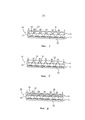
Фиг.1: поперечное боковое сечение одного варианта осуществления инкапсулированной оптической системы данного изобретения, где в оптической системе используется матрица собирающих (например, выпуклых) линз;Figure 1: cross-sectional side view of one embodiment of the encapsulated optical system of the present invention, where an array of collecting (e.g., convex) lenses is used in the optical system;
Фиг.2: поперечное боковое сечение другого варианта осуществления инкапсулированной оптической системы данного изобретения, где в оптической системе используется матрица рассеивающих (например, вогнутых) линз;Figure 2: cross-sectional side view of another embodiment of the encapsulated optical system of the present invention, where an array of scattering (eg, concave) lenses is used in the optical system;
Фиг.3: поперечное боковое сечение другого варианта осуществления инкапсулированной оптической системы данного изобретения, где в оптической системе используется матрица собирающих (например, выпуклых) градиентных линз (граданов).Figure 3: cross-sectional side view of another embodiment of the encapsulated optical system of the present invention, where an optical system uses a matrix of collecting (e.g., convex) gradient lenses (gradans).
ПОДРОБНОЕ ОПИСАНИЕ ИЗОБРЕТЕНИЯDETAILED DESCRIPTION OF THE INVENTION
[0021] Как подробно описано, например, в Патенте США №7,333,268, выданном на имя Стинблика и др., фокусное расстояние фокусирующих элементов в микрооптических материалах определяет оптическое разделение фокусирующих элементов от матрицы пиктограмм изображений. Иными словами, матрицы в этих уже известных микрооптических материалах располагаются таким образом, чтобы совместить фокальную точку каждого фокусирующего элемента с соответствующими им пиктограммами изображений. Когда фокальная точка находится на матрице пиктограмм изображений или в ее пределах, синтетическое изображение находится в резком фокусе. Однако если фокальная точка находится выше или ниже матрицы пиктограмм изображений, то синтетическое изображение является размытым и находится не в фокусе.[0021] As described in detail, for example, in US Patent No. 7,333,268, issued to Steenblick et al., The focal length of the focusing elements in micro-optical materials determines the optical separation of the focusing elements from the matrix of image icons. In other words, the matrices in these already known micro-optical materials are arranged in such a way as to align the focal point of each focusing element with the corresponding image pictograms. When the focal point is on or within the matrix of image icons, the synthetic image is in sharp focus. However, if the focal point is above or below the matrix of image icons, the synthetic image is blurry and out of focus.
[0022] С помощью примеров осуществления данного изобретения геометрия фокусирующих элементов (например, микролинз) и коэффициенты преломления как первого, так и второго материалов подгоняются для достижения требуемого фокусного расстояния, и, соответственно, оптического разделения (при наличии такового) между матрицами. Без такой подгонки фокусное расстояние фокусирующих элементов будет либо слишком большим или слишком малым (т.е. фокусное расстояние каждого фокусирующего элемента будет попадать выше или ниже матрицы пиктограмм изображений), из-за чего система не сможет сформировать одно или несколько синтетических изображений.[0022] Using embodiments of the present invention, the geometry of the focusing elements (for example, microlenses) and the refractive indices of both the first and second materials are adjusted to achieve the desired focal length, and, accordingly, optical separation (if any) between the matrices. Without this adjustment, the focal length of the focusing elements will be either too large or too small (i.e., the focal length of each focusing element will fall above or below the matrix of image icons), because of which the system will not be able to form one or more synthetic images.
[0023] Физические свойства компонентов в этих примерах осуществления изобретения предназначены для работы только в сочетании друг с другом. Как это сразу становится понятным для лиц, сведущих в данной области техники, при подгонке фокусирующих элементов для получения требуемого фокусного расстояния обычно рассматриваются радиус кривизны и коэффициенты преломления материалов, используемых для изготовления фокусирующих элементов, и окружающего (инкапсулирующего) материала (обычно - воздуха). Разница между коэффициентами в сочетании с радиусом кривизны определяют угол преломления. При использовании градиентных (граданных) материалов радиус кривизны определяется концентрацией градиента, которая вместе с разницей между коэффициентами преломления определяет угол преломления.[0023] The physical properties of the components in these embodiments are intended to work only in combination with each other. As this immediately becomes apparent to those skilled in the art, when fitting focusing elements to obtain the required focal length, the radius of curvature and the refractive indices of the materials used to manufacture the focusing elements and the surrounding (encapsulating) material (usually air) are usually considered. The difference between the coefficients in combination with the radius of curvature determines the angle of refraction. When using gradient (gradational) materials, the radius of curvature is determined by the concentration of the gradient, which together with the difference between the refractive indices determines the angle of refraction.
[0024] Изобретенная оптическая система будет далее описана по одному из примеров ее осуществления как система, включающая (а) одну или несколько структур пиктограмм изображений и (b) одну или несколько частично или полностью включенных структур фокусирующих элементов пиктограмм изображений, коэффициент преломления которых изменяется в интервале между первым и вторым коэффициентами преломления, причем первый коэффициент преломления значительно или измеримо отличается от второго коэффициента преломления.[0024] The inventive optical system will be described below in one example of its implementation as a system comprising (a) one or more structures of image icons and (b) one or more partially or fully included structures of focusing elements of image icons, the refractive index of which varies in the interval between the first and second refractive indices, the first refractive index being significantly or measurably different from the second refractive index.
[0025] Структуры фокусирующих элементов пиктограмм изображений могут формироваться из одного или нескольких материалов. Формируемые из одного материала структуры фокусирующих элементов пиктограмм изображений с изменяющимся коэффициентом преломления могут приготавливаться, например, посредством выборочной полимеризации материала, осуществляемой таким образом, чтобы степень сшивания полимера следовала за градиентом.[0025] The structures of the focusing elements of the image icons may be formed from one or more materials. The structures of focusing elements of image pictograms with varying refractive index formed from the same material can be prepared, for example, by selectively polymerizing the material so that the degree of polymer crosslinking follows the gradient.
[0026] Одна или несколько структур фокусирующих элементов пиктограмм изображений, используемые в данном изобретении, могут выбираться из группы, в которую входят:[0026] One or more of the focusing element structures of image icons used in the present invention may be selected from the group consisting of:
i. матрица цилиндрических или нецилиндрических линз (например, микролинз, включая собирающие (например, выпуклые) линзы, рассеивающие (например, вогнутые) линзы, градиентные линзы (граданы), воздушные линзы;i. a matrix of cylindrical or non-cylindrical lenses (for example, microlenses, including collecting (for example, convex) lenses, scattering (for example, concave) lenses, gradient lenses (gradans), air lenses;
ii. непрозрачный слой, содержащий многочисленные апертуры (пример: оптика микроотверстий); иii. an opaque layer containing numerous apertures (example: micro-hole optics); and
iii. отражающий слой.iii. reflective layer.
[0027] В одном предпочтительном варианте осуществления изобретения фокусирующие элементы являются нецилиндрическими выпуклыми или вогнутыми микролинзами со сферической или асферической поверхностью. Асферические поверхности включают конические, эллиптические, параболические и другие профили. Эти линзы могут иметь круглую, овальную или многоугольную (например, шестиугольную, в значительной степени шестиугольную, квадратную, в значительной степени квадратную) геометрию основания и могут размещаться в упорядоченных, неупорядоченных или произвольных одномерных или двухмерных матрицах.[0027] In one preferred embodiment, the focusing elements are non-cylindrical convex or concave microlenses with a spherical or aspherical surface. Aspherical surfaces include conical, elliptical, parabolic and other profiles. These lenses may have round, oval, or polygonal (e.g., hexagonal, substantially hexagonal, square, substantially square) base geometry and may be arranged in ordered, disordered, or arbitrary one-dimensional or two-dimensional matrices.
[0028] В более предпочтительном варианте осуществления изобретения микролинзы являются асферическими вогнутыми или выпуклыми линзами с многоугольной (например, шестиугольной) геометрией основания, размещенными в упорядоченной двухмерной матрице на подкладке или светопроводящей полимерной пленке.[0028] In a more preferred embodiment, the microlenses are aspherical concave or convex lenses with a polygonal (eg, hexagonal) geometry of the base, placed in an ordered two-dimensional matrix on a lining or light guide polymer film.
[0029] В другом более предпочтительном варианте осуществления изобретения фокусирующие элементы являются выпуклыми или вогнутыми граданными микролинзами.[0029] In another more preferred embodiment, the focusing elements are convex or concave gradual microlenses.
[0030] В одном из предполагаемых вариантов осуществления изобретения фокусирующие элементы имеют предпочтительную ширину (при использовании цилиндрических линз) и предпочтительный диаметр основания (при использовании нецилиндрических линз) менее 1 миллиметра или 1 миллиметр, включая среди прочего следующие значения ширины и эффективного диаметра: от приблизительно 200 до приблизительно 500 микрон и от приблизительно 50 до приблизительно 199 микрон, предпочтительные фокусные расстояния менее 1 миллиметра или 1 миллиметр, включая среди прочего указанные выше поддиапазоны, и предпочтительные числа f менее 10 или равные 10 (более предпочтительно - менее 6 или равные 6). В другом предполагаемом варианте осуществления изобретения фокусирующие элементы имеют предпочтительную ширину и предпочтительный диаметр основания менее приблизительно 50 микрон (более предпочтительно - менее приблизительно 45 микрон и наиболее предпочтительно - от приблизительно 10 до приблизительно 40 микрон), предпочтительные фокусные расстояния менее приблизительно 50 микрон (более предпочтительно - менее приблизительно 45 микрон, и наиболее предпочтительно - от приблизительно 10 до приблизительно 30 микрон), и предпочтительные числа f менее 10 или равные 10 (более предпочтительно - менее 6 или равные 6).[0030] In one contemplated embodiment, the focusing elements have a preferred width (when using cylindrical lenses) and a preferred base diameter (when using non-cylindrical lenses) of less than 1 millimeter or 1 millimeter, including, but not limited to, the following widths and effective diameters: from approximately 200 to about 500 microns and from about 50 to about 199 microns, preferred focal lengths of less than 1 millimeter or 1 millimeter, including but not limited to the above sub-ranges, and preferred numbers f less than 10 or equal to 10 (more preferably less than 6 or equal to 6). In another contemplated embodiment, the focusing elements have a preferred width and a preferred base diameter of less than about 50 microns (more preferably less than about 45 microns and most preferably from about 10 to about 40 microns), preferred focal lengths less than about 50 microns (more preferably less than about 45 microns, and most preferably from about 10 to about 30 microns), and preferred numbers f less than 10 or equal to 10 (more preferably less than 6 or equal to 6).
[0031] Одна или несколько структур пиктограмм изображений, используемых в данном изобретении, предпочтительно состоят из микро-структурированных пиктограмм изображений (т.е. из пиктограмм изображений, имеющих физический рельеф).[0031] One or more of the image icon structures used in this invention preferably consists of micro-structured image icons (ie, image icons having a physical profile).
[0032] В одном предполагаемом варианте осуществления данного изобретения пиктограммы изображений являются необязательно покрываемыми и(или) заполняемыми пустотами или углублениями, формируемыми на подкладке или внутри нее. Общая глубина каждой пустоты или каждого углубления - от приблизительно 0,5 до приблизительно 8 микрон.[0032] In one contemplated embodiment of the present invention, the image thumbnails are optionally covered and / or filled with voids or indentations formed on or within the lining. The total depth of each void or each depression is from about 0.5 to about 8 microns.
[0033] В другом предполагаемом варианте осуществления изобретения пиктограммы изображений формируются из имеющих определенную форму столбиков, устраиваемых на поверхности подкладки, общая высота каждого из которых - от приблизительно 0,5 до приблизительно 8 микрон.[0033] In another contemplated embodiment, image thumbnails are formed from shaped columns arranged on the surface of the lining, the total height of each of which is from about 0.5 to about 8 microns.
[0034] Хотя это и не требуется данным изобретением, оптическое разделение между структурами фокусирующих элементов и пиктограммами изображений может быть достигнуто за счет использования оптической прокладки. В одном из таких вариантов осуществления изобретения оптическая прокладка прикрепляется к структурам фокусирующих элементов. В другом варианте осуществления изобретения оптическая прокладка может формироваться как часть структур фокусирующих элементов, или толщина структур фокусирующих элементов может увеличиваться для того, чтобы структуры могли быть свободностоящими. В еще одном варианте осуществления изобретения оптическая прокладка прикрепляется к другой оптической прокладке.[0034] Although not required by this invention, optical separation between the structures of the focusing elements and the pictograms of the images can be achieved by using an optical pad. In one such embodiment, the optical spacer is attached to the structures of the focusing elements. In another embodiment of the invention, the optical spacer can be formed as part of the structures of the focusing elements, or the thickness of the structures of the focusing elements can be increased so that the structures can be self-supporting. In yet another embodiment, the optical spacer is attached to another optical spacer.
[0035] Оптическая прокладка может формироваться с использованием одного или нескольких практически бесцветных материалов, включая среди прочего такие полимеры, как поликарбонат, полиэстер, полиэтилен, полиэтиленнафталат, полиэтилентерефталат, полипропилен, поливинилиденхлорид и тому подобные.[0035] An optical spacer can be formed using one or more substantially colorless materials, including but not limited to polymers such as polycarbonate, polyester, polyethylene, polyethylene naphthalate, polyethylene terephthalate, polypropylene, polyvinylidene chloride, and the like.
[0036] Как подробно описано в Патенте США №7,333,268, выданном на имя Стинблика и др., Патенте США №7,468,842, выданном на имя Стинблика и др., и Патенте США №7,738,175, выданном на имя Стинблика и др., матрицы фокусирующих элементов и пиктограмм изображений могут формироваться из разнообразных материалов, таких как в значительной степени прозрачные или чистые цветные или бесцветные полимеры - акриловые полимеры, акрилированные полиэфиры, акрилированные уретаны, эпоксидные смолы, поликарбонаты, полипропилены, полиэфиры, уретаны и тому подобное с использованием разнообразных методов, известных в области микрооптики и репликации микроструктур, включая экструзию (например, экструзивное тиснение, мягкое тиснение), отливку с радиационным отверждением, литье под давлением, реактивное литье под давлением и реактивную отливку. Цветные и бесцветные материалы с высокими коэффициентами преломления (при 589 нм, 20°C) более 1,5, 1,6, 1,7 и выше, такие как материалы, описанные в Публикации заявки US 2010/0109317 А1 на имя Хоффмюллера и др., также могут использоваться при практическом осуществлении данного изобретения.[0036] As described in detail in US Patent No. 7,333,268, issued in the name of Steenblick et al., US Patent No. 7,468,842 issued in the name of Stinblick et al., And US Patent No. 7,738,175, issued in the name of Stinblick et al., Matrix of focusing elements and pictograms of images can be formed from a variety of materials, such as substantially transparent or pure color or colorless polymers - acrylic polymers, acrylic polyesters, acrylic urethanes, epoxies, polycarbonates, polypropylenes, polyesters, urethanes and the like using aniem variety of methods known in the field of microoptics and replication of the microstructures, including extrusion (e.g., extrusion embossing, soft embossing), molding with radiation curing, injection molding, reaction injection molding and casting reactive. Colored and colorless materials with high refractive indices (at 589 nm, 20 ° C) of more than 1.5, 1.6, 1.7 and higher, such as the materials described in Publication of the application US 2010/0109317 A1 in the name of Hoffmüller and others ., can also be used in the practical implementation of the present invention.
[0037] Пример метода изготовления описанных здесь вариантов осуществления изобретения заключается в следующем: пиктограммы формируются как пустоты в отверждаемом с помощью радиации жидком полимере (например, акрилированном уретане), отливаемом на служащей основанием пленке (т.е. оптической прокладке), например, на полиэтилентерефталатной пленке (ПЭТФ) калибра 75 с повышенной адгезионной прочностью, затем из отверждаемого с помощью радиации жидкого полимера на противоположной поверхности, служащей основанием пленки, формируются линзы с надлежащей регулировкой наклона относительно пиктограмм, после этого пустоты пиктограмм на поверхности пленки заполняются красителем, пигментированным субмикронными частицами, с помощью скребка-лопатки (как при изготовлении гравюр), а заполняющий материал (отверждается соответствующим способом (например, удалением растворителя, применением радиации или осуществлением химической реакции).[0037] An example of a manufacturing method for the embodiments described herein is as follows: pictograms are formed as voids in a radiation curable liquid polymer (eg, acrylated urethane) cast on a base film (ie, optical pad), for example a polyethylene terephthalate film (PET) of caliber 75 with increased adhesive strength, then lenses are formed on the opposite surface serving as the base of the film from radiation-cured liquid polymer proper adjustment of the inclination relative to the pictograms, after which the voids of the pictograms on the film surface are filled with dye pigmented with submicron particles using a scraper blade (as in the manufacture of engravings), and the filling material (is cured by an appropriate method (for example, removing solvent, using radiation, or using chemical reactions).
[0038] Второй материал имеет коэффициент преломления, значительно или измеримо отличный от коэффициента преломления материала, используемого для формирования фокусирующих элементов (т.е. первого материала). В частности, разница между этими коэффициентами преломления приводит к изменению фокусного расстояния фокусирующих элементов, по меньшей мере, на приблизительно 0,1 микрона.[0038] The second material has a refractive index that is significantly or measurably different from the refractive index of the material used to form the focusing elements (ie, the first material). In particular, the difference between these refractive indices leads to a change in the focal length of the focusing elements by at least about 0.1 microns.
[0039] Второй материал может быть прозрачным, просвечивающим, тонированным или пигментированным и может обеспечивать дополнительную функциональность в том, что касается защиты и аутентификации, включая поддержку систем автоматической аутентификации, проверки, счета и распознавания валюты и слежения за валютой, в работе которых используются оптические эффекты, электропроводность, емкостное сопротивление и обнаружение магнитного поля. Подходящие материалы могут включать адгезивы, гели, клеи, лаки, жидкости, формованные полимеры, полимеры или другие материалы, содержащие дисперсии органических веществ или металлов.[0039] The second material may be transparent, translucent, tinted or pigmented and may provide additional functionality in terms of protection and authentication, including support for automatic authentication systems, verification, account and currency recognition and currency tracking, which use optical effects, electrical conductivity, capacitance and magnetic field detection. Suitable materials may include adhesives, gels, adhesives, varnishes, liquids, molded polymers, polymers or other materials containing dispersions of organic substances or metals.
[0040] Второй материал наносится либо на первый материал структуры фокусирующих элементов, либо одновременно и на первый материал структуры фокусирующих элементов и на структуру пиктограмм изображений с помощью прозрачной печати, формовки, растворимого геля (осаждения раствора химикатов), нанесения покрытия поливом или скребком-лопаткой, нанесения покрытия заливкой, просушки и отверждения на открытом воздухе, нанесения покрытия и отверждения с помощью ультрафиолета (УФ)/энергии с использованием гладкого цилиндра, ламинирования пленкой с адгезивным слоем, с использованием анилоксового или дозирующего вала, испарения, химического осаждения из паровой фазы (CVD), физического осаждения из паровой фазы (PVD) или с помощью любых других способов нанесения вещества на поверхность, включая описанные в Патенте США №7,333,268, выданном на имя Стинблика и др., Патенте США №7,468,842, выданном на имя Стинблика и др., и Патенте США №7,738,175, выданном на имя Стинблика и др., которые, как указано выше, полностью включены в этот документ посредством ссылок, как если бы они были изложены здесь в полном объеме.[0040] The second material is applied either to the first material of the structure of the focusing elements, or simultaneously to the first material of the structure of the focusing elements and the structure of the image icons using transparent printing, molding, soluble gel (deposition of a solution of chemicals), coating with irrigation or scraper-spatula , coating by pouring, drying and curing in the open air, coating and curing with ultraviolet (UV) / energy using a smooth cylinder, film lamination an adhesive layer using an anilox or metering roll, vaporization, chemical vapor deposition (CVD), physical vapor deposition (PVD), or any other method of applying a substance to a surface, including those described in US Pat. No. 7,333,268, issued the name of Steenblick et al., US Patent No. 7,468,842, issued to the name of Stinblick et al., and US Patent No. 7,738,175, issued to the name of Stinblick and others, which, as indicated above, are fully incorporated into this document by reference, as if they have been set forth here in full e.
[0041] Оптическая система данного изобретения может также включать дополнительные особенности, например те, что описаны в Патенте США №7,333,268, выданном на имя Стинблика и др., Патенте США №7,468,842, выданном на имя Стинблика и др., и Патенте США №7,738,175, выданном на имя Стинблика и др. Например, изобретенная система может также включать текстурированные поверхности для лучшей адгезии к последующим слоям, активаторы склеивания и т.д.[0041] The optical system of this invention may also include additional features, for example, those described in US Patent No. 7,333,268, issued in the name of Steenblick and others, US Patent No. 7,468,842, issued in the name of Stinblick and others, and US Patent No. 7,738,175 issued in the name of Steenblick et al. For example, the invented system may also include textured surfaces for better adhesion to subsequent layers, adhesion promoters, etc.
[0042] Изобретенная оптическая система далее будет описана, раскрыта, иллюстрирована и показана ниже в одной из ее простейших форм как система, в основном состоящая из (а) матрицы пиктограмм изображений и (b) матрицы полностью включенных фокусирующих элементов пиктограмм изображений. В соответствии с намерениями изобретателей объем данного изобретения не ограничивается и не должен считаться ограниченным приводимым ниже примером; права на другие подобные варианты осуществления изобретения, показанные или предложенные в изложенном здесь, а также в публикациях, заявках на патенты, патентах и других упомянутых здесь справочных материалах, сохраняются.[0042] The inventive optical system will hereinafter be described, disclosed, illustrated and shown below in one of its simplest forms as a system mainly consisting of (a) a matrix of image icons and (b) a matrix of fully included focusing elements of image icons. In accordance with the intentions of the inventors, the scope of this invention is not limited and should not be considered limited by the following example; rights to other similar embodiments of the invention shown or proposed in the foregoing, as well as in publications, patent applications, patents, and other reference materials mentioned here, are reserved.
[0043] На Фиг.1 и 2 в разделе чертежей в общем показаны примеры осуществления системы данного изобретения (10). Система 10 в основном включает следующее:[0043] Figs. 1 and 2 in the drawings section generally show exemplary embodiments of the system of the present invention (10).
(a) матрицу пиктограмм изображений 12;(a) an
(b) матрицу фокусирующих элементов пиктограмм изображений 14, сформированную из первого материала 16, имеющего коэффициент преломления (n1), при этом матрица фокусирующих элементов пиктограмм изображений 14 состоит из собирающих (например, выпуклых) линз 18 на Фиг.1 и рассеивающих (например, вогнутых) линз 20 на Фиг.2;(b) a matrix of focusing elements of pictograms of
(c) второй материал 22, имеющий коэффициент преломления (n2); и(c) a
(d) оптическую прокладку 24, расположенную между матрицей пиктограмм изображений 12 и матрицей фокусирующих элементов пиктограмм изображений 14,(d) an
где второй материал 22 также образует слой на матрице пиктограмм изображений 12, тем самым полностью инкапсулируя систему.where the
[0044] В этих примерах осуществления изобретения геометрия линз и коэффициенты преломления n1 и n2 подгоняются для получения требуемого фокусного расстояния, которое в обоих этих вариантах осуществления изобретения больше нуля.[0044] In these embodiments, the lens geometry and refractive indices n1 and n2 are adjusted to obtain the desired focal length, which in both of these embodiments is greater than zero.
[0045] В другом примере осуществления изобретенной системы, обозначенном цифрой 26 на Фиг.3, фокусирующие элементы пиктограмм изображений являются выпуклыми граданными микролинзами 28. В этом случае коэффициент преломления изменяется в пространстве между внешними границами второго и первого материалов 22, 16. Этот градиент коэффициента преломления может образовываться посредством процесса диффузии с использованием определенного температурного режима, различных материалов с различной молекулярной массой, растворимости одного из материалов в другом или смешиваемости одного из материалов с другим или выборочного отверждения таким образом, чтобы степень сшивания полимера следовала за градиентом, или с использованием других способов, известных лицам, сведущим в данной области техники. Второй материал 22 в этом варианте осуществления изобретения образует слой на матрице пиктограмм изображений 12, тем самым полностью инкапсулируя систему.[0045] In another example embodiment of the inventive system, indicated by 26 in FIG. 3, the focusing elements of the image icons are convex, graded
[0046] Как было указано выше, изобретенная система может использоваться в виде, например, защитной полосы, нити, накладки или покрытия и наноситься на поверхность волокнистого или неволокнистого листового материала, или, по меньшей мере, частично включаться в такой материал (примеры: банкноты, паспорта, идентификационные карточки, кредитные карты, этикетки), или использоваться в коммерческих продуктах (примеры: оптические диски, компакт-диски, диски DVD, упаковки медикаментов) и т.д. для аутентификации. Изобретенная система также может использоваться в виде отдельного продукта (например, подкладки для последующей печати или персонализации) или в виде неволокнистого листового материала, используемого в изготовлении, например, банкнот, паспортов и тому подобного, или приобретать утолщенную и более прочную форму для использования в качестве, например, базовой платформы для идентификационных карточек, обладающих высокой ценностью документов и прочих защищаемых документов.[0046] As indicated above, the inventive system can be used in the form of, for example, a protective strip, thread, lining or coating and applied to the surface of a fibrous or non-fibrous sheet material, or at least partially included in such a material (examples: banknotes , passports, ID cards, credit cards, labels), or used in commercial products (examples: optical discs, CDs, DVDs, medicine packaging), etc. for authentication. The inventive system can also be used as a separate product (for example, linings for subsequent printing or personalization) or in the form of non-fibrous sheet material used in the manufacture of, for example, banknotes, passports and the like, or to acquire a thicker and more durable form for use as for example, a basic platform for identification cards with high value of documents and other protected documents.
[0047] При использовании в виде защитной полосы, нити, накладки или покрытия общая толщина изобретенной системы предпочтительно менее приблизительно 50 микрон (более предпочтительно - менее приблизительно 45 микрон, а наиболее предпочтительно - от приблизительно 10 до приблизительно 40 микрон). Матрица фокусирующих элементов пиктограмм изображений предпочтительно формируется из первого материала, выбираемого из группы, в которую входят акрилированные уретаны, эпоксиакрилаты и олигомеры акриловых смол, при этом первый материал имеет коэффициент преломления от приблизительно 1,5 до приблизительно 1,8, и из второго материала, выбираемого из группы, в которую входят уретанакрилаты и мономеры акриловых смол, при этом второй материал имеет коэффициент преломления от приблизительно 1,35 до приблизительно 1,49. Более предпочтительно, чтобы первый материал являлся модифицированным эпоксиакрилатом, который можно приобрести в компании «Сартомер Ю-Эс-Эй Эл-Эл-Си» (502 Томас Джонс Уэй, г.Экстон, штат Пенсильвания, 19341) (далее - «Сартомер»), код изделия CN115, при этом первый материал имеет коэффициент преломления от приблизительно 1,549 до приблизительно 1,56, а второй материал является изодецилакрилатом, который можно приобрести в компании «Сартомер» (код изделия SR395), при этом второй материал имеет коэффициент преломления от приблизительно 1,44 до приблизительно 1,45.[0047] When used as a protective strip, thread, patch or coating, the total thickness of the invented system is preferably less than about 50 microns (more preferably less than about 45 microns, and most preferably from about 10 to about 40 microns). The matrix of focusing elements of the pictograms of images is preferably formed from the first material selected from the group consisting of acrylated urethanes, epoxy acrylates and oligomers of acrylic resins, the first material having a refractive index of from about 1.5 to about 1.8, and from the second material, selected from the group consisting of urethane acrylates and monomers of acrylic resins, the second material having a refractive index of from about 1.35 to about 1.49. It is more preferred that the first material be a modified epoxy acrylate, which can be purchased from Sartomer USA Al-El-Si (502 Thomas Jones Way, Exton, PA, 19341) (hereinafter “Sartomer”) , product code CN115, wherein the first material has a refractive index of from about 1.549 to about 1.56, and the second material is isodecyl acrylate, which can be purchased from Sartomer (product code SR395), while the second material has a refractive index of approximately 1.44 to approximate of 1.45.
[0048] Защитные полосы, нити, накладки или покрытия могут быть частично включены в документ или установлены на его поверхности. При частичном включении полос и нитей определенные их части выходят на поверхность документа с заданными интервалами по длине полосы или нити в окнах или апертурах, устроенных в документе.[0048] Protective strips, threads, overlays or coatings may be partially incorporated into or mounted on a surface of a document. With the partial inclusion of strips and threads, certain parts of them go to the surface of the document at predetermined intervals along the length of the strip or thread in the windows or apertures arranged in the document.
[0049] Изобретенные оптические защитные устройства могут быть, по меньшей мере, частично включены в защищаемые бумажные продукты, при их изготовлении с использованием технологий, повсеместно используемых в бумажной промышленности. Например, изобретенное защитное устройство в виде полосы или нити может подаваться в бумагоделательную машину с формующим цилиндром, в машину с ванной цилиндра или в подобную машину известного типа для полного или частичного включения полосы или нити в структуру готовой бумаги.[0049] The inventive optical security devices can be at least partially incorporated into security paper products when manufactured using technologies commonly used in the paper industry. For example, the inventive security device in the form of a strip or thread can be fed into a paper machine with a forming cylinder, into a machine with a cylinder bath, or into a similar machine of a known type for completely or partially incorporating a strip or thread into the structure of the finished paper.
[0050] Защитные полосы, нити, накладки или покрытия могут также прикрепляться к поверхности документа с использованием или без использования адгезива. Соединение без использования адгезива может достигаться с помощью, например, технологий термической сварки - ультразвуковой сварки, вибрационной сварки, лазерной плавки. Адгезивы для прикрепления изобретенных устройств к поверхности документа могут являться разновидностями термоклея, адгезивами с термической активацией, адгезивами, реагирующими на давление, полимерными ламинирующими пленками. Эти адгезивы предпочтительно являются поперечно сшиваемыми (отверждаемые ультрафиолетом акриловые или эпоксидные смолы); поперечное сшивание происходит, когда адгезив пребывает в расплавленном состоянии.[0050] Protective strips, threads, overlays or coatings may also be attached to the surface of the document with or without adhesive. The connection without the use of adhesive can be achieved using, for example, thermal welding technologies - ultrasonic welding, vibration welding, laser melting. Adhesives for attaching the inventive devices to the surface of a document may be hot melt adhesives, thermal activation adhesives, pressure sensitive adhesives, polymer laminating films. These adhesives are preferably crosslinkable (UV curable acrylic or epoxy resins); Crosslinking occurs when the adhesive is in a molten state.
[0051] В другом предполагаемом варианте осуществления изобретения система формирует часть конструкции этикетки, содержащую прозрачный или просвечивающий адгезив (т.е. второй материал), находящийся в контакте с первым материалом структуры фокусирующих элементов или слоя линз. Изобретенная система может размещаться на внутренней стороне упаковки таким образом, чтобы синтетическое(ие) изображение(я) было(и) видно(ы).[0051] In another contemplated embodiment, the system forms a portion of the label structure containing a transparent or translucent adhesive (ie, a second material) in contact with the first material of the structure of the focusing elements or layer of lenses. The invented system can be placed on the inside of the package so that the synthetic image (s) are (are) visible (s).
[0052] При использовании в качестве базовой платформы для идентификационных карточек, имеющих большую ценность документов или других защищаемых документов, общая толщина изобретенной системы предпочтительно составляет менее приблизительно 1 миллиметра (мм) или равна приблизительно 1 мм, в том числе среди прочего толщина находится в следующих интервалах: от приблизительно 200 до приблизительно 500 микрон; от приблизительно 50 до приблизительно 199 микрон, а также составляет менее приблизительно 50 микрон. Матрица фокусирующих элементов пиктограмм изображений предпочтительно формируется из первого материала, выбираемого из группы, в которую входят уретанакрилаты и мономеры акриловых смол, при этом первый материал имеет коэффициент преломления от приблизительно 1,35 до приблизительно 1,49. Второй материал предпочтительно выбирается из группы, в которую входят эпоксиакрилаты, олигомеры полиэфиров, поли(ароматические карбонаты) и поли(алифатические карбонаты), при этом второй материал имеет коэффициент преломления от приблизительно 1,5 до приблизительно 1,8. Более предпочтительно, чтобы первый материал являлся три(пропиленгликоль)диакрилатом, который можно приобрести в компании «Сартомер» (код изделия SR306), при этом первый материал имеет коэффициент преломления от приблизительно 1,449 до приблизительно 1,46, а второй материал являлся поликарбонатом, который можно приобрести в компании «Байер МатириалСаенс АГ» (Кайзер-Вильгельм-Аллее, 51368, г.Леверкузен, Германия), при этом второй материал имеет коэффициент преломления от приблизительно 1,584 до приблизительно 1,685.[0052] When used as a base platform for identification cards having high value of documents or other security documents, the total thickness of the invented system is preferably less than about 1 millimeter (mm) or equal to about 1 mm, including, but not limited to, the thickness is in the following intervals: from about 200 to about 500 microns; from about 50 to about 199 microns, and is also less than about 50 microns. The matrix of focusing elements of the image pictograms is preferably formed from a first material selected from the group consisting of urethane acrylates and acrylic resin monomers, the first material having a refractive index of from about 1.35 to about 1.49. The second material is preferably selected from the group consisting of epoxy acrylates, polyester oligomers, poly (aromatic carbonates) and poly (aliphatic carbonates), the second material having a refractive index of from about 1.5 to about 1.8. More preferably, the first material is three (propylene glycol) diacrylate, which can be purchased from Sartomer (product code SR306), the first material having a refractive index of from about 1.499 to about 1.46, and the second material is polycarbonate, which can be purchased from Bayer MatirialSaens AG (Kaiser-Wilhelm-Allee, 51368, Leverkusen, Germany), while the second material has a refractive index of from about 1.584 to about 1.685.
[0053] В этом варианте осуществления изобретения из вогнутых линз формируется оптическая прокладка с использованием материала, имеющего меньший коэффициент преломления (т.е. первого материала). Слой поликарбоната, имеющего больший коэффициент преломления (т.е. второй материал), помещается поверх вогнутых линз. Затем под воздействием высокой температуры и давления выдавливается и удаляется попавший внутрь воздух, а поликарбонат вводится в полости линз. После охлаждения система создает находящиеся в резком фокусе синтетические изображения с гладким защитным верхним слоем.[0053] In this embodiment, an optical spacer is formed from concave lenses using a material having a lower refractive index (ie, the first material). A polycarbonate layer having a higher refractive index (i.e., a second material) is placed over concave lenses. Then, under the influence of high temperature and pressure, the air that has got inside is squeezed out and removed, and polycarbonate is introduced into the lens cavity. After cooling, the system creates sharp focus synthetic images with a smooth protective top layer.
[0054] Несмотря на то, что различные варианты осуществления данного изобретения описаны выше, необходимо понимать, что они приведены лишь в качестве примеров и не имеют ограничивающий характер. Поэтому масштаб и объем данного изобретения не ограничиваются какими-либо примерами его осуществления.[0054] Although various embodiments of the present invention have been described above, it should be understood that they are provided by way of example only and are not restrictive. Therefore, the scope and scope of the present invention are not limited to any examples of its implementation.
Claims (67)
Applications Claiming Priority (3)
| Application Number | Priority Date | Filing Date | Title |
|---|---|---|---|
| US12/820,320 US8867134B2 (en) | 2003-11-21 | 2010-06-22 | Optical system demonstrating improved resistance to optically degrading external effects |
| US12/820,320 | 2010-06-22 | ||
| PCT/US2011/041348 WO2011163298A1 (en) | 2010-06-22 | 2011-06-22 | An optical system demonstrating improved resistance to optically degrading external effects |
Publications (3)
| Publication Number | Publication Date |
|---|---|
| RU2013101539A RU2013101539A (en) | 2014-07-27 |
| RU2602487C2 RU2602487C2 (en) | 2016-11-20 |
| RU2602487C9 true RU2602487C9 (en) | 2017-08-29 |
Family
ID=43300192
Family Applications (1)
| Application Number | Title | Priority Date | Filing Date |
|---|---|---|---|
| RU2013101539A RU2602487C9 (en) | 2010-06-22 | 2011-06-22 | Optical system having higher resistance to external influence affecting optical properties |
Country Status (12)
| Country | Link |
|---|---|
| US (1) | US8867134B2 (en) |
| EP (1) | EP2585861B1 (en) |
| JP (2) | JP2013537640A (en) |
| KR (1) | KR101946656B1 (en) |
| CN (1) | CN103097919B (en) |
| AU (1) | AU2011271030C1 (en) |
| BR (1) | BR112012033221B1 (en) |
| CA (1) | CA2803857C (en) |
| ES (1) | ES2731671T3 (en) |
| MX (1) | MX2013000197A (en) |
| RU (1) | RU2602487C9 (en) |
| WO (1) | WO2011163298A1 (en) |
Families Citing this family (52)
| Publication number | Priority date | Publication date | Assignee | Title |
|---|---|---|---|---|
| US8020754B2 (en) | 2001-08-13 | 2011-09-20 | Jpmorgan Chase Bank, N.A. | System and method for funding a collective account by use of an electronic tag |
| US8867134B2 (en) * | 2003-11-21 | 2014-10-21 | Visual Physics, Llc | Optical system demonstrating improved resistance to optically degrading external effects |
| USD636021S1 (en) | 2008-07-17 | 2011-04-12 | Jpmorgan Chase Bank, N.A. | Eco-friendly transaction device |
| AT510366B1 (en) * | 2010-08-27 | 2012-12-15 | Hueck Folien Gmbh | VALUE DOCUMENT WITH AT LEAST PARTIALLY EMBEDDED SAFETY ELEMENT |
| FR2968239B1 (en) * | 2010-12-07 | 2012-12-21 | Hologram Ind | SECURE PRODUCT AND METHOD OF MAKING SAID SECURE PRODUCT |
| MY159709A (en) | 2011-01-28 | 2017-01-13 | Crane & Co Inc | A laser marked device |
| BR112013033917A2 (en) | 2011-06-28 | 2019-09-24 | Visual Physics Llc | optical film laminate weak or null winding paper |
| IN2014CN02023A (en) | 2011-08-19 | 2015-05-29 | Visual Physics Llc | |
| AU2012322328B2 (en) * | 2011-10-14 | 2016-07-21 | 3Dtl, Inc. | Security element or document with a security feature including at least one dynamic-effect feature |
| DE102011117677A1 (en) * | 2011-11-04 | 2013-05-08 | Giesecke & Devrient Gmbh | Optically variable security element |
| KR101203199B1 (en) * | 2012-02-03 | 2012-11-21 | (주)쓰리에스엠케이 | Injection-molded products with stereoscopic security element and the producing method thereof |
| CN103358808B (en) * | 2012-03-28 | 2015-12-16 | 中钞特种防伪科技有限公司 | A kind of optical anti-counterfeit element and use the product of this optical anti-counterfeit element |
| WO2013188518A1 (en) | 2012-06-13 | 2013-12-19 | Visual Physics, Llc | Micro-optic material with improved abrasion resistance |
| KR102014576B1 (en) | 2012-08-17 | 2019-08-26 | 비쥬얼 피직스 엘엘씨 | A process for transferring microstructures to a final substrate |
| EP2767395A1 (en) * | 2013-02-15 | 2014-08-20 | KBA-NotaSys SA | Substrate for security papers and method of manufacturing the same |
| BR112015022369A2 (en) | 2013-03-15 | 2017-07-18 | Visual Physics Llc | optical safety device |
| US9873281B2 (en) | 2013-06-13 | 2018-01-23 | Visual Physics, Llc | Single layer image projection film |
| CN103342060B (en) * | 2013-06-18 | 2016-01-20 | 坤达国际有限公司 | A kind of Three-dimensional printed matter and stereoscopic picture printing technique |
| GB201313362D0 (en) * | 2013-07-26 | 2013-09-11 | Rue De Int Ltd | Security Devices and Methods of Manufacture |
| DE102013108485B4 (en) | 2013-08-06 | 2015-06-25 | Khs Gmbh | Device and method for error tracking in strip materials |
| WO2015034896A1 (en) * | 2013-09-05 | 2015-03-12 | 3M Innovative Properties Company | Double-sided optical film with lenslets and clusters of prisms |
| JP2017522602A (en) * | 2014-03-27 | 2017-08-10 | ビジュアル フィジクス エルエルシー | Optical device that produces flicker-like optical effects |
| US10766292B2 (en) | 2014-03-27 | 2020-09-08 | Crane & Co., Inc. | Optical device that provides flicker-like optical effects |
| DE102014004700A1 (en) | 2014-03-31 | 2015-10-01 | Giesecke & Devrient Gmbh | Security element with a lenticular image |
| CA2950253C (en) * | 2014-05-20 | 2019-02-12 | Lumenco, Llc | Slant lens interlacing with linearly arranged lenses |
| ES2721757T3 (en) * | 2014-07-17 | 2019-08-05 | Visual Physics Llc | Improved polymeric sheet material for use in obtaining polymeric security documents such as banknotes |
| KR102189819B1 (en) * | 2014-09-01 | 2020-12-14 | 삼성디스플레이 주식회사 | Organic light emitting display apparatus |
| AU2015317844B2 (en) | 2014-09-16 | 2019-07-18 | Crane Security Technologies, Inc. | Secure lens layer |
| US10859851B2 (en) | 2014-10-24 | 2020-12-08 | Wavefront Technology, Inc. | Optical products, masters for fabricating optical products, and methods for manufacturing masters and optical products |
| US20160121640A1 (en) * | 2014-11-04 | 2016-05-05 | Lumenco, Llc | Flat concave micro lens for security as an integrated focusing element |
| WO2016130822A1 (en) | 2015-02-11 | 2016-08-18 | Crane & Co., Inc. | Method for the surface application of a security device to a substrate |
| CN105988228B (en) * | 2015-02-13 | 2020-07-31 | 北京三星通信技术研究有限公司 | Three-dimensional display device and three-dimensional display method thereof |
| US10252563B2 (en) | 2015-07-13 | 2019-04-09 | Wavefront Technology, Inc. | Optical products, masters for fabricating optical products, and methods for manufacturing masters and optical products |
| US10286716B2 (en) * | 2015-10-27 | 2019-05-14 | Ecole Polytechnique Fédérale Lausanne (EPFL) | Synthesis of superposition shape images by light interacting with layers of lenslets |
| WO2017163778A1 (en) * | 2016-03-23 | 2017-09-28 | 株式会社エンプラス | Marker |
| US10850550B2 (en) | 2016-04-22 | 2020-12-01 | Wavefront Technology, Inc. | Optical switch devices |
| US11113919B2 (en) | 2017-10-20 | 2021-09-07 | Wavefront Technology, Inc. | Optical switch devices |
| TW201805191A (en) * | 2016-07-22 | 2018-02-16 | 日商富士軟片股份有限公司 | Three-dimensional molded object |
| US10864762B2 (en) | 2016-08-15 | 2020-12-15 | Visual Physics, Llc | Anti-harvestable security feature |
| CA3051876A1 (en) | 2017-02-10 | 2018-08-16 | Crane & Co., Inc. | Authentication and anti-harvesting security feature with machine detectable indicia |
| ES2922024T3 (en) | 2017-02-10 | 2022-09-06 | Crane & Co Inc | Optical machine-readable security device |
| CN107367247B (en) * | 2017-06-09 | 2019-12-13 | 北京工业大学 | Frequency multiplication type microstrip patch antenna strain sensor |
| WO2019136171A1 (en) | 2018-01-03 | 2019-07-11 | Visual Physics, Llc | Micro-optic security device with interactive dynamic security features |
| FR3079052A1 (en) * | 2018-03-16 | 2019-09-20 | Idemia France | DOCUMENT TO GENERATE A COLOR IMAGE |
| CN109433694B (en) * | 2018-10-18 | 2020-11-03 | 浙江富兴服装有限公司 | Pet that takes drying function from comprehensive clearance stings ball cleaning device |
| US11668977B2 (en) | 2018-12-14 | 2023-06-06 | 3M Innovative Properties Company | Liquid crystal display having a frontside light control film |
| CN113195238B (en) * | 2018-12-27 | 2023-10-31 | 克瑞尼股份有限公司 | Surface application type low-light anti-counterfeiting safety device |
| CN111619262B (en) * | 2019-02-28 | 2021-05-11 | 中钞特种防伪科技有限公司 | Optical anti-counterfeiting element and anti-counterfeiting product |
| CN109870821A (en) * | 2019-04-03 | 2019-06-11 | 冯煜 | A kind of focusing structure and the method for realizing naked eye 3D display |
| WO2020214239A1 (en) | 2019-04-19 | 2020-10-22 | Wavefront Technology, Inc. | Optical switch devices |
| CA3141584A1 (en) | 2019-05-20 | 2020-11-26 | Crane & Co., Inc. | Use of nanoparticles to tune index of refraction of layers of a polymeric matrix to optimize microoptic (mo) focus |
| WO2022204441A1 (en) * | 2021-03-24 | 2022-09-29 | Simpson Interventions, Inc. | Oct catheter with low refractive index optical material |
Citations (4)
| Publication number | Priority date | Publication date | Assignee | Title |
|---|---|---|---|---|
| US20030112523A1 (en) * | 2000-03-17 | 2003-06-19 | Stephen Daniell | Lens arrays |
| US20030179364A1 (en) * | 2002-01-24 | 2003-09-25 | Nanoventions, Inc. | Micro-optics for article identification |
| WO2005106601A2 (en) * | 2004-04-30 | 2005-11-10 | De La Rue International Limited | Arrays of microlenses and arrays of microimages on transparent security substrates |
| US20070291362A1 (en) * | 2006-06-20 | 2007-12-20 | Applied Opsec, Inc. | Optically variable device with diffraction-based micro-optics, method of creating the same, and article employing the same |
Family Cites Families (221)
| Publication number | Priority date | Publication date | Assignee | Title |
|---|---|---|---|---|
| US992151A (en) | 1909-02-04 | 1911-05-16 | Rodolphe Berthon | Apparatus for color photography. |
| US1824353A (en) | 1926-12-15 | 1931-09-22 | Jensen Rasmus Olaf Jonas | Screen for showing projected images in lighted rooms and for shortexposure photography |
| US1849036A (en) | 1926-12-23 | 1932-03-08 | Victor C Ernst | Photographic process and auxiliary element therefor |
| US1942841A (en) | 1931-01-19 | 1934-01-09 | Shimizu Takeo | Daylight screen |
| US2268351A (en) | 1938-08-25 | 1941-12-30 | Tanaka Nawokich | Means for presenting pictures in apparent three dimensions |
| US2355902A (en) | 1941-04-10 | 1944-08-15 | Photoplating Company | Sign with animated effect |
| US2432896A (en) | 1945-03-12 | 1947-12-16 | Hotchner Fred | Retroreflective animation display |
| NL110404C (en) | 1955-03-29 | |||
| US2888855A (en) | 1956-08-23 | 1959-06-02 | Tanaka Nawokich | Means for presenting pictures in three dimensional effect |
| US3122853A (en) | 1961-08-10 | 1964-03-03 | John C Koonz | Fishing lure |
| US3264164A (en) | 1962-04-30 | 1966-08-02 | Toscony Inc | Color dynamic, three-dimensional flexible film and method of making it |
| US3241429A (en) | 1962-05-14 | 1966-03-22 | Pid Corp | Pictorial parallax panoramagram units |
| US3357772A (en) | 1963-02-27 | 1967-12-12 | Rowland Products Inc | Phased lenticular sheets for optical effects |
| GB1095286A (en) | 1963-07-08 | 1967-12-13 | Portals Ltd | Security device for use in security papers |
| US3312006A (en) | 1964-03-11 | 1967-04-04 | Rowland Products Inc | Motion displays |
| JPS414953Y1 (en) | 1964-07-28 | 1966-03-18 | ||
| JPS4622600Y1 (en) | 1965-07-02 | 1971-08-05 | ||
| US3463581A (en) | 1966-01-17 | 1969-08-26 | Intermountain Res & Eng | System for three-dimensional panoramic static-image motion pictures |
| US3811213A (en) | 1968-11-17 | 1974-05-21 | Photo Motion Corp | Moire motion illusion apparatus and method |
| JPS4941718B1 (en) | 1968-12-30 | 1974-11-11 | ||
| US3643361A (en) | 1969-11-17 | 1972-02-22 | Photo Motion Corp | Moire motion illusion apparatus |
| BE789941A (en) | 1971-04-21 | 1973-02-01 | Waly Adnan | MINIATURIZED IMAGE RECORDING AND PLAYBACK SYSTEM |
| US4025673A (en) | 1972-04-13 | 1977-05-24 | Reinnagel Richard E | Method of forming copy resistant documents by forming an orderly array of fibers extending upward from a surface, coating the fibers and printing the coated fibers and the copy resistant document resulting from said method |
| US3887742A (en) | 1972-04-13 | 1975-06-03 | Richard E Reinnagel | Copy resistant documents |
| US4105318A (en) | 1974-05-30 | 1978-08-08 | Izon Corporation | Pinhole microfiche recorder and viewer |
| US4082426A (en) | 1976-11-26 | 1978-04-04 | Minnesota Mining And Manufacturing Company | Retroreflective sheeting with retroreflective markings |
| US4185191A (en) | 1978-06-05 | 1980-01-22 | Honeywell Inc. | Range determination system |
| US4498736A (en) | 1981-02-02 | 1985-02-12 | Griffin Robert B | Method and apparatus for producing visual patterns with lenticular sheets |
| US4417784A (en) | 1981-02-19 | 1983-11-29 | Rca Corporation | Multiple image encoding using surface relief structures as authenticating device for sheet-material authenticated item |
| US4892385A (en) | 1981-02-19 | 1990-01-09 | General Electric Company | Sheet-material authenticated item with reflective-diffractive authenticating device |
| US4345833A (en) | 1981-02-23 | 1982-08-24 | American Optical Corporation | Lens array |
| DE3211102A1 (en) | 1982-03-25 | 1983-10-06 | Schwarz Klaus Billett Automat | METHOD FOR AUTHENTICITY CONTROL OF PAPER SECTIONS AND USE OF A COLOR REACTION SYSTEM SUITABLE FOR THIS |
| JPS58175091A (en) | 1982-04-06 | 1983-10-14 | 株式会社東芝 | Security thread detector |
| US4814594A (en) | 1982-11-22 | 1989-03-21 | Drexler Technology Corporation | Updatable micrographic pocket data card |
| US4645301A (en) | 1983-02-07 | 1987-02-24 | Minnesota Mining And Manufacturing Company | Transparent sheet containing authenticating image and method of making same |
| US4634220A (en) | 1983-02-07 | 1987-01-06 | Minnesota Mining And Manufacturing Company | Directionally imaged sheeting |
| US4507349A (en) | 1983-05-16 | 1985-03-26 | Howard A. Fromson | Security medium and secure articles and methods of making same |
| NL8400868A (en) | 1984-03-19 | 1984-10-01 | Philips Nv | LAYERED OPTICAL COMPONENT. |
| US4534398A (en) | 1984-04-30 | 1985-08-13 | Crane & Co. | Security paper |
| US4688894A (en) | 1985-05-13 | 1987-08-25 | Minnesota Mining And Manufacturing Company | Transparent retroreflective sheets containing directional images and method for forming the same |
| US4662651A (en) | 1985-05-31 | 1987-05-05 | The Standard Register Company | Document protection using multicolor characters |
| DE3687560D1 (en) | 1985-10-15 | 1993-03-04 | Gao Ges Automation Org | DATA CARRIER WITH AN OPTICAL AUTHENTICITY CHARACTER, AND METHOD FOR PRODUCING AND CHECKING THE DATA CARRIER. |
| US4920039A (en) | 1986-01-06 | 1990-04-24 | Dennison Manufacturing Company | Multiple imaging |
| US4935335A (en) | 1986-01-06 | 1990-06-19 | Dennison Manufacturing Company | Multiple imaging |
| DE3609090A1 (en) | 1986-03-18 | 1987-09-24 | Gao Ges Automation Org | SECURITY PAPER WITH SECURED THREAD STORED IN IT AND METHOD FOR THE PRODUCTION THEREOF |
| CH670904A5 (en) | 1986-07-10 | 1989-07-14 | Landis & Gyr Ag | |
| DE3741179A1 (en) | 1987-12-04 | 1989-06-15 | Gao Ges Automation Org | DOCUMENT WITH FALSE-PROOF SURFACE RELIEF AND METHOD FOR PRODUCING THE SAME |
| IN173621B (en) | 1987-12-04 | 1994-06-18 | Portals Ltd | |
| DE69033853T2 (en) | 1989-01-31 | 2002-06-13 | Dainippon Printing Co Ltd | Thermal transfer recording methods and thermal transfer image receiving sheets |
| JPH0355501A (en) | 1989-07-25 | 1991-03-11 | Nippon Sheet Glass Co Ltd | Lens array plate |
| US5085514A (en) | 1989-08-29 | 1992-02-04 | American Bank Note Holographics, Inc. | Technique of forming a separate information bearing printed pattern on replicas of a hologram or other surface relief diffraction pattern |
| US4988151A (en) | 1989-08-31 | 1991-01-29 | Hughes Aircraft Company | Method for making edge faded holograms |
| US5695346A (en) | 1989-12-07 | 1997-12-09 | Yoshi Sekiguchi | Process and display with moveable images |
| US6724536B2 (en) | 1990-05-18 | 2004-04-20 | University Of Arkansas | Directional image lenticular window sheet |
| US6870681B1 (en) | 1992-09-21 | 2005-03-22 | University Of Arkansas, N.A. | Directional image transmission sheet and method of making same |
| US5232764A (en) | 1990-06-04 | 1993-08-03 | Meiwa Gravure Co., Ltd. | Synthetic resin pattern sheet |
| US5215864A (en) | 1990-09-28 | 1993-06-01 | Laser Color Marking, Incorporated | Method and apparatus for multi-color laser engraving |
| US5254390B1 (en) | 1990-11-15 | 1999-05-18 | Minnesota Mining & Mfg | Plano-convex base sheet for retroreflective articles |
| JP3120401B2 (en) | 1991-01-08 | 2000-12-25 | 日本ビクター株式会社 | Optical card |
| GB9106128D0 (en) | 1991-03-22 | 1991-05-08 | Amblehurst Ltd | Article |
| GB9113462D0 (en) | 1991-06-21 | 1991-08-07 | Pizzanelli David J | Laser-activated bar-code holograms and bar-code recognition system |
| US5384861A (en) | 1991-06-24 | 1995-01-24 | Picker International, Inc. | Multi-parameter image display with real time interpolation |
| US5211424A (en) | 1991-08-15 | 1993-05-18 | Prc Inc. | Secure passport document and method of making the same |
| US5626969A (en) | 1992-02-21 | 1997-05-06 | General Binding Corporation | Method of manufacturing film for lamination |
| DK95292D0 (en) | 1992-07-23 | 1992-07-23 | Frithioff Johansen | PROCEDURE AND DISPLAY TO PROVIDE AN ENLARGED PICTURE OF A TWO-DIMENSIONAL PERIODIC PICTURE PATTERN |
| US5359454A (en) | 1992-08-18 | 1994-10-25 | Applied Physics Research, L.P. | Apparatus for providing autostereoscopic and dynamic images |
| DE4243987C2 (en) | 1992-12-23 | 2003-10-09 | Gao Ges Automation Org | ID cards with visually visible authenticity |
| GB9309673D0 (en) | 1993-05-11 | 1993-06-23 | De La Rue Holographics Ltd | Security device |
| US5393099A (en) | 1993-05-21 | 1995-02-28 | American Bank Note Holographics, Inc. | Anti-counterfeiting laminated currency and method of making the same |
| US5449200A (en) | 1993-06-08 | 1995-09-12 | Domtar, Inc. | Security paper with color mark |
| US5555476A (en) | 1993-08-30 | 1996-09-10 | Toray Industries, Inc. | Microlens array sheet for a liquid crystal display, method for attaching the same and liquid crystal display equipped with the same |
| EP0722098B1 (en) | 1993-09-30 | 2003-01-29 | Grapac Japan Co., Inc. | Lens manufacturing method, lensed article manufacturing method, lensed article, and partition-forming resin composition |
| US6345104B1 (en) | 1994-03-17 | 2002-02-05 | Digimarc Corporation | Digital watermarks and methods for security documents |
| US5598281A (en) | 1993-11-19 | 1997-01-28 | Alliedsignal Inc. | Backlight assembly for improved illumination employing tapered optical elements |
| KR0135922B1 (en) * | 1993-12-16 | 1998-04-27 | 다테이시 요시오 | Liquid crystal projector and liquid crystal display device using micro lens plate |
| DE4344553A1 (en) | 1993-12-24 | 1995-06-29 | Giesecke & Devrient Gmbh | Security paper with a thread-like or ribbon-shaped security element and method for producing the same |
| GB9400942D0 (en) | 1994-01-19 | 1994-03-16 | De La Rue Thomas & Co Ltd | Copy indicating security device |
| US5464690A (en) | 1994-04-04 | 1995-11-07 | Novavision, Inc. | Holographic document and method for forming |
| US5933276A (en) | 1994-04-13 | 1999-08-03 | Board Of Trustees, University Of Arkansas, N.A. | Aberration-free directional image window sheet |
| US6373965B1 (en) | 1994-06-24 | 2002-04-16 | Angstrom Technologies, Inc. | Apparatus and methods for authentication using partially fluorescent graphic images and OCR characters |
| FR2722303B1 (en) | 1994-07-07 | 1996-09-06 | Corning Inc | METHOD AND DEVICE FOR MANUFACTURING OPTICAL MICROLENTIAL NETWORKS |
| GB9415780D0 (en) | 1994-08-04 | 1994-09-28 | Portals Ltd | A security thread, a film and a method of manufacture of a security thread |
| US6036230A (en) | 1994-10-11 | 2000-03-14 | Oesterreichische National Bank | Paper, especially security paper |
| US5642226A (en) | 1995-01-18 | 1997-06-24 | Rosenthal; Bruce A. | Lenticular optical system |
| US5604635A (en) | 1995-03-08 | 1997-02-18 | Brown University Research Foundation | Microlenses and other optical elements fabricated by laser heating of semiconductor doped and other absorbing glasses |
| GB9509487D0 (en) | 1995-05-10 | 1995-07-05 | Ici Plc | Micro relief element & preparation thereof |
| US5639126A (en) | 1995-06-06 | 1997-06-17 | Crane & Co., Inc. | Machine readable and visually verifiable security threads and security papers employing same |
| EP0853296B1 (en) | 1995-08-01 | 2004-07-07 | Boris Iliich Belousov | Tape data carrier, method and device for manufacturing the same |
| US5886798A (en) | 1995-08-21 | 1999-03-23 | Landis & Gyr Technology Innovation Ag | Information carriers with diffraction structures |
| US5995638A (en) | 1995-08-28 | 1999-11-30 | Ecole Polytechnique Federale De Lausanne | Methods and apparatus for authentication of documents by using the intensity profile of moire patterns |
| DE19541064A1 (en) | 1995-11-03 | 1997-05-07 | Giesecke & Devrient Gmbh | Data carrier with an optically variable element |
| DE69636991T2 (en) | 1995-11-28 | 2007-12-06 | Ovd Kinegram Ag | Optical information carrier |
| US7114750B1 (en) | 1995-11-29 | 2006-10-03 | Graphic Security Systems Corporation | Self-authenticating documents |
| CN1126970C (en) | 1996-01-17 | 2003-11-05 | 布鲁斯·A·罗森塔尔 | Lenticular optical system |
| JP2761861B2 (en) | 1996-02-06 | 1998-06-04 | 明和グラビア株式会社 | Decorative sheet |
| EP0900433A1 (en) | 1996-05-20 | 1999-03-10 | Minnesota Mining And Manufacturing Company | Tamper indicating multilayer sheet |
| GB9612496D0 (en) | 1996-06-14 | 1996-08-14 | De La Rue Thomas & Co Ltd | Security device |
| US6819775B2 (en) | 1996-07-05 | 2004-11-16 | ECOLE POLYTECHNIQUE FéDéRALE DE LAUSANNE | Authentication of documents and valuable articles by using moire intensity profiles |
| JPH1039108A (en) * | 1996-07-19 | 1998-02-13 | Toray Ind Inc | Manufacture of microlens array sheet |
| RU2111125C1 (en) | 1996-08-14 | 1998-05-20 | Молохина Лариса Аркадьевна | Decorative base for personal visiting, business or identification card, souvenir or congratulatory card, or illustration, or monetary document |
| AUPO260296A0 (en) | 1996-09-26 | 1996-10-24 | Reserve Bank Of Australia | Banknotes incorporating security devices |
| AUPO289296A0 (en) | 1996-10-10 | 1996-10-31 | Securency Pty Ltd | Self-verifying security documents |
| KR100194536B1 (en) | 1996-10-17 | 1999-06-15 | 김충환 | 3D effect handbill and its manufacturing method |
| US6060143A (en) | 1996-11-14 | 2000-05-09 | Ovd Kinegram Ag | Optical information carrier |
| DE59610252D1 (en) | 1996-12-12 | 2003-04-24 | Ovd Kinegram Ag Zug | SURFACE PATTERN |
| US6362868B1 (en) | 1997-07-15 | 2002-03-26 | Silverbrook Research Pty Ltd. | Print media roll and ink replaceable cartridge |
| AUPP044197A0 (en) | 1997-11-19 | 1997-12-11 | Securency Pty Ltd | Moire security device |
| US6930606B2 (en) | 1997-12-02 | 2005-08-16 | Crane & Co., Inc. | Security device having multiple security detection features |
| JP3131771B2 (en) | 1997-12-26 | 2001-02-05 | 明和グラビア株式会社 | Decorative sheet with three-dimensional effect |
| DE19804858A1 (en) | 1998-01-30 | 1999-08-05 | Ralf Dr Paugstadt | Methods and devices for producing lenticular alternating images |
| JP3931936B2 (en) | 1998-05-11 | 2007-06-20 | セイコーエプソン株式会社 | Microlens array substrate, method for manufacturing the same, and display device |
| CA2239671C (en) | 1998-06-04 | 2007-10-02 | H.B. Fuller Licensing & Financing, Inc. | Waterborne primer and oxygen barrier coating with improved adhesion |
| DE19825950C1 (en) | 1998-06-12 | 2000-02-17 | Armin Grasnick | Arrangement for three-dimensional representation |
| IL125210A (en) | 1998-07-05 | 2003-03-12 | Mvt Multi Vision Technologies | Computerized method for creating a multi-image print |
| US6256149B1 (en) | 1998-09-28 | 2001-07-03 | Richard W. Rolfe | Lenticular lens sheet and method of making |
| US6301363B1 (en) | 1998-10-26 | 2001-10-09 | The Standard Register Company | Security document including subtle image and system and method for viewing the same |
| DE69925086T2 (en) | 1998-10-30 | 2006-02-02 | Avery Dennison Corp., Pasadena | Retroreflective sheeting with an image for authenticity testing and process for its preparation |
| GB9828770D0 (en) | 1998-12-29 | 1999-02-17 | Rue De Int Ltd | Security paper |
| JP2000256994A (en) | 1999-03-10 | 2000-09-19 | Tokushu Paper Mfg Co Ltd | Windowed thread paper |
| JP3505617B2 (en) | 1999-06-09 | 2004-03-08 | ヤマックス株式会社 | Virtual image appearance decoration |
| DE19932240B4 (en) | 1999-07-10 | 2005-09-01 | Bundesdruckerei Gmbh | Optically variable displayable / concealable security elements for value and security documents |
| US6751024B1 (en) | 1999-07-22 | 2004-06-15 | Bruce A. Rosenthal | Lenticular optical system |
| GB9917442D0 (en) | 1999-07-23 | 1999-09-29 | Rue De Int Ltd | Security device |
| GB9918617D0 (en) | 1999-08-07 | 1999-10-13 | Epigem Limited | An optical display composite |
| JP2003510648A (en) | 1999-09-30 | 2003-03-18 | コーニンクレッカ フィリップス エレクトロニクス エヌ ヴィ | Lenticular device |
| JP2000098490A (en) * | 1999-09-30 | 2000-04-07 | Hitachi Ltd | Display device |
| JP2001141908A (en) | 1999-11-12 | 2001-05-25 | Seiko Epson Corp | Method for manufacturing microlens substrate, microlens substrate, counter substrate for liquid crystal panel, liquid crystal panel and projection display device |
| ATE268927T1 (en) | 1999-11-29 | 2004-06-15 | Ecole Polytech | NEW METHOD AND APPARATUS FOR AUTHENTICATING DOCUMENTS BY USING MOIRE PATTERNS INTENSITY PROFILE |
| FR2803939B1 (en) | 2000-01-18 | 2002-03-01 | Rexor | SECURITY WIRE OR TRANSFER FILM FOR HOT MARKING FOR BANK NOTES, DOCUMENTS OR OTHER SECURITY ARTICLES |
| CA2397806C (en) | 2000-01-21 | 2009-05-05 | Flex Products, Inc. | Optically variable security devices |
| US20010048968A1 (en) | 2000-02-16 | 2001-12-06 | Cox W. Royall | Ink-jet printing of gradient-index microlenses |
| US6288842B1 (en) | 2000-02-22 | 2001-09-11 | 3M Innovative Properties | Sheeting with composite image that floats |
| US7336422B2 (en) | 2000-02-22 | 2008-02-26 | 3M Innovative Properties Company | Sheeting with composite image that floats |
| US7068434B2 (en) | 2000-02-22 | 2006-06-27 | 3M Innovative Properties Company | Sheeting with composite image that floats |
| US7254265B2 (en) | 2000-04-01 | 2007-08-07 | Newsight Corporation | Methods and systems for 2D/3D image conversion and optimization |
| GB2362493B (en) | 2000-04-04 | 2004-05-12 | Floating Images Ltd | Advertising hoarding,billboard or poster with high visual impact |
| JP4013450B2 (en) | 2000-05-16 | 2007-11-28 | 凸版印刷株式会社 | Dot pattern display medium and manufacturing method thereof |
| GB0013379D0 (en) | 2000-06-01 | 2000-07-26 | Optaglio Ltd | Label and method of forming the same |
| GB0015871D0 (en) | 2000-06-28 | 2000-08-23 | Rue De Int Ltd | A security device |
| US6424467B1 (en) | 2000-09-05 | 2002-07-23 | National Graphics, Inc. | High definition lenticular lens |
| US6500526B1 (en) | 2000-09-28 | 2002-12-31 | Avery Dennison Corporation | Retroreflective sheeting containing a validation image and methods of making the same |
| ES2273883T3 (en) | 2000-10-05 | 2007-05-16 | Trub Ag | SUPPORT FOR DATA RECORDING. |
| EP1346315A4 (en) | 2000-11-02 | 2008-06-04 | Taylor Corp | Lenticular card and processes for making |
| DE10139719A1 (en) | 2000-11-04 | 2002-05-08 | Kurz Leonhard Fa | Multi-layer body, in particular multi-layer film and method for increasing the security against forgery of a multi-layer body |
| US6450540B1 (en) | 2000-11-15 | 2002-09-17 | Technology Tree Co., Ltd | Printed matter displaying various colors according to view angle |
| DE10058638A1 (en) | 2000-11-25 | 2002-06-13 | Orga Kartensysteme Gmbh | Method for producing a data carrier and a data carrier |
| US6795250B2 (en) | 2000-12-29 | 2004-09-21 | Lenticlear Lenticular Lens, Inc. | Lenticular lens array |
| US6833960B1 (en) | 2001-03-05 | 2004-12-21 | Serigraph Inc. | Lenticular imaging system |
| US20030205895A1 (en) | 2001-03-27 | 2003-11-06 | Scarbrough Joel Scott | Reflective printed article and method of manufacturing same |
| US6726858B2 (en) | 2001-06-13 | 2004-04-27 | Ferro Corporation | Method of forming lenticular sheets |
| GB0117096D0 (en) | 2001-07-13 | 2001-09-05 | Qinetiq Ltd | Security label |
| GB0117391D0 (en) | 2001-07-17 | 2001-09-05 | Optaglio Ltd | Optical device and method of manufacture |
| JP2003039583A (en) | 2001-07-27 | 2003-02-13 | Meiwa Gravure Co Ltd | Decorative sheet |
| DE10139653A1 (en) | 2001-08-11 | 2003-02-20 | Tesa Ag | Label with increased protection against counterfeiting |
| US7030997B2 (en) | 2001-09-11 | 2006-04-18 | The Regents Of The University Of California | Characterizing aberrations in an imaging lens and applications to visual testing and integrated circuit mask analysis |
| JP3909238B2 (en) | 2001-11-30 | 2007-04-25 | 日本写真印刷株式会社 | Printed matter with micropattern |
| WO2003052680A1 (en) | 2001-12-18 | 2003-06-26 | Digimarc Id System, Llc | Multiple image security features for identification documents and methods of making same |
| DE10226114A1 (en) | 2001-12-21 | 2003-07-03 | Giesecke & Devrient Gmbh | Security element for security papers and documents of value |
| PL372119A1 (en) | 2001-12-21 | 2005-07-11 | Giesecke & Devrient Gmbh | Devices and methods for the production of sheet material |
| DE10163266A1 (en) | 2001-12-21 | 2003-07-03 | Giesecke & Devrient Gmbh | Document of value and device for processing documents of value |
| GB0201767D0 (en) | 2002-01-25 | 2002-03-13 | Rue De Int Ltd | Improvements in methods of manufacturing substrates |
| US6856462B1 (en) | 2002-03-05 | 2005-02-15 | Serigraph Inc. | Lenticular imaging system and method of manufacturing same |
| EP1490236B2 (en) | 2002-04-03 | 2022-03-16 | De La Rue International Limited | Optically variable security device |
| US6943952B2 (en) | 2002-04-08 | 2005-09-13 | Hologram Industries (Sa) | Optical security component |
| AT504463A1 (en) | 2002-04-11 | 2008-05-15 | Hueck Folien Gmbh | COATED SUPPORT SUBSTRATE, PREFERABLY WITH BOTH DIFFERENT OPTICAL AND / OR FLUORESCENT CHARACTERISTICS |
| EP1511620A4 (en) | 2002-05-17 | 2009-08-05 | Visual Physics Llc | Microstructured taggant particles, applications and methods of making the same |
| US6983048B2 (en) | 2002-06-06 | 2006-01-03 | Graphic Security Systems Corporation | Multi-section decoding lens |
| US6935756B2 (en) | 2002-06-11 | 2005-08-30 | 3M Innovative Properties Company | Retroreflective articles having moire-like pattern |
| JP2004021814A (en) | 2002-06-19 | 2004-01-22 | Konica Minolta Holdings Inc | Ic card and creation method therefor |
| US7058202B2 (en) | 2002-06-28 | 2006-06-06 | Ecole polytechnique fédérale de Lausanne (EPFL) | Authentication with built-in encryption by using moire intensity profiles between random layers |
| MXPA05001528A (en) | 2002-08-13 | 2005-04-11 | Giesecke & Devrient Gmbh | Data carrier comprising an optically variable structure. |
| DE10243863A1 (en) | 2002-08-13 | 2004-02-26 | Giesecke & Devrient Gmbh | Data carrier, e.g. a banknote, with at least a security marking area to prevent counterfeiting in the form of an optically variable embossed structure with optically varying coatings arranged over the embossed area |
| US7751608B2 (en) | 2004-06-30 | 2010-07-06 | Ecole Polytechnique Federale De Lausanne (Epfl) | Model-based synthesis of band moire images for authenticating security documents and valuable products |
| US7194105B2 (en) | 2002-10-16 | 2007-03-20 | Hersch Roger D | Authentication of documents and articles by moiré patterns |
| US6803088B2 (en) | 2002-10-24 | 2004-10-12 | Eastman Kodak Company | Reflection media for scannable information system |
| RU2245566C2 (en) | 2002-12-26 | 2005-01-27 | Молохин Илья Валерьевич | Light-reflecting layout material |
| JP4391103B2 (en) | 2003-03-03 | 2009-12-24 | 大日本印刷株式会社 | Authenticator and authenticator label |
| US7763179B2 (en) | 2003-03-21 | 2010-07-27 | Digimarc Corporation | Color laser engraving and digital watermarking |
| WO2004087430A1 (en) | 2003-04-02 | 2004-10-14 | Ucb, S.A. | Authentication means |
| US20040209049A1 (en) | 2003-04-17 | 2004-10-21 | Marco Bak | Laser marking in retroreflective security laminate |
| BRPI0409596A (en) | 2003-04-21 | 2006-05-02 | 3M Innovative Properties Co | violation indicating device, and article |
| US20080130018A1 (en) | 2003-05-19 | 2008-06-05 | Nanoventions, Inc. | Microstructured Taggant Particles, Applications and Methods of Making the Same |
| KR20060065731A (en) | 2003-09-22 | 2006-06-14 | 진 돌고프 | Omnidirectional lenticular and barrier-grid image displays and methods for making them |
| US7389939B2 (en) | 2003-09-26 | 2008-06-24 | Digimarc Corporation | Optically variable security features having covert forensic features |
| DE10351129B4 (en) * | 2003-11-03 | 2008-12-24 | Ovd Kinegram Ag | Diffractive security element with a halftone image |
| US8867134B2 (en) * | 2003-11-21 | 2014-10-21 | Visual Physics, Llc | Optical system demonstrating improved resistance to optically degrading external effects |
| EP2311647B1 (en) | 2003-11-21 | 2018-01-10 | Visual Physics, LLC | Micro-optic security and image presentation system |
| JP2005234036A (en) * | 2004-02-17 | 2005-09-02 | Seiko Epson Corp | Large-sized substrate, chip-like substrate, electrooptical apparatus using chip-like substrate, and method for manufacturing chip-like substrate |
| US7576918B2 (en) | 2004-07-20 | 2009-08-18 | Pixalen, Llc | Matrical imaging method and apparatus |
| US7504147B2 (en) | 2004-07-22 | 2009-03-17 | Avery Dennison Corporation | Retroreflective sheeting with security and/or decorative image |
| EP1771758A2 (en) | 2004-07-26 | 2007-04-11 | Applied Opsec, Inc. | Diffraction-based optical grating structure and method of creating the same |
| US7686187B2 (en) | 2004-08-26 | 2010-03-30 | Scott V. Anderson | Apparatus and method for open thread, reusable, no-waste collapsible tube dispensers with control ribs and/or detent |
| JP4285373B2 (en) | 2004-09-01 | 2009-06-24 | セイコーエプソン株式会社 | Microlens manufacturing method, microlens and microlens array, and electro-optical device and electronic apparatus |
| EP1801636B1 (en) * | 2004-09-10 | 2008-10-08 | Sumitomo Electric Industries, Ltd. | Transluscent display panel and method for manufacturing the same |
| US7524617B2 (en) | 2004-11-23 | 2009-04-28 | E.I. Du Pont De Nemours And Company | Low-temperature curable photosensitive compositions |
| DE102005028162A1 (en) | 2005-02-18 | 2006-12-28 | Giesecke & Devrient Gmbh | Security element for protecting valuable objects, e.g. documents, includes focusing components for enlarging views of microscopic structures as one of two authenication features |
| JP4484738B2 (en) * | 2005-03-18 | 2010-06-16 | 富士フイルム株式会社 | Photosensitive composition and planographic printing plate precursor |
| WO2006125224A2 (en) * | 2005-05-18 | 2006-11-23 | Nanoventions Holdings, Llc. | Image presentation and micro-optic security system |
| US20070092680A1 (en) | 2005-10-26 | 2007-04-26 | Sterling Chaffins | Laser writable media substrate, and systems and methods of laser writing |
| DE102005062132A1 (en) | 2005-12-23 | 2007-07-05 | Giesecke & Devrient Gmbh | Security unit e.g. seal, for e.g. valuable document, has motive image with planar periodic arrangement of micro motive units, and periodic arrangement of lens for moire magnified observation of motive units |
| US7812935B2 (en) | 2005-12-23 | 2010-10-12 | Ingenia Holdings Limited | Optical authentication |
| BRPI0707515A2 (en) | 2006-02-06 | 2011-05-10 | Rubbermaid Commercial Products | crate receptacle |
| KR20090028523A (en) | 2006-05-12 | 2009-03-18 | 크레인 앤드 캄파니 인코퍼레이티드 | A micro-optic film structure that alone or together with a security document or label projects images spatially coordinated with static images and/or other projected images |
| JP2007310142A (en) * | 2006-05-18 | 2007-11-29 | Konica Minolta Medical & Graphic Inc | Image recording body, manufacturing method of image recording body and manufacturing apparatus of image recording body |
| US7457039B2 (en) | 2006-06-07 | 2008-11-25 | Genie Lens Technologies, Llc | Lenticular display system with a lens sheet spaced apart from a paired interlaced image |
| KR101376434B1 (en) | 2006-06-28 | 2014-04-01 | 비쥬얼 피직스 엘엘씨 | Micro-optic security and image presentation system |
| EP1876028A1 (en) | 2006-07-07 | 2008-01-09 | Setec Oy | Method for producing a data carrier and data carrier produced therefrom |
| DE102006034854A1 (en) | 2006-07-25 | 2008-01-31 | Ovd Kinegram Ag | A method for generating a laser mark in a security document and such a security document |
| DE102007005414A1 (en) * | 2007-01-30 | 2008-08-07 | Ovd Kinegram Ag | Security element for securing value documents |
| DE102007007914A1 (en) | 2007-02-14 | 2008-08-21 | Giesecke & Devrient Gmbh | Embossing lacquer for micro-optical safety elements |
| DE102007029203A1 (en) | 2007-06-25 | 2009-01-08 | Giesecke & Devrient Gmbh | security element |
| DE102007029204A1 (en) | 2007-06-25 | 2009-01-08 | Giesecke & Devrient Gmbh | security element |
| JP5163036B2 (en) * | 2007-09-27 | 2013-03-13 | 凸版印刷株式会社 | Display and labeled goods |
| WO2009121784A2 (en) | 2008-04-01 | 2009-10-08 | Agfa Gevaert | Security laminate having a security feature |
| MX2011000592A (en) | 2008-07-15 | 2011-05-27 | Azuna Llc | Method and assembly for personalized three-dimensional products. |
| DE102008036482A1 (en) | 2008-08-05 | 2010-02-11 | Giesecke & Devrient Gmbh | Method for producing microlenses |
| TWI382239B (en) | 2008-09-12 | 2013-01-11 | Eternal Chemical Co Ltd | Optical film |
| RO127445B1 (en) | 2009-03-04 | 2018-08-30 | Ccl Secure Pty Ltd | Lens arrays and method for producing lens arrays |
| DE102009023715A1 (en) | 2009-06-03 | 2010-12-09 | Leonhard Kurz Stiftung & Co. Kg | The security document |
| EP3626474A1 (en) | 2009-08-12 | 2020-03-25 | Visual Physics, LLC | A tamper indicating optical security device |
| EP2335937B1 (en) | 2009-12-18 | 2013-02-20 | Agfa-Gevaert | Laser markable security film |
-
2010
- 2010-06-22 US US12/820,320 patent/US8867134B2/en active Active
-
2011
- 2011-06-22 JP JP2013516710A patent/JP2013537640A/en active Pending
- 2011-06-22 BR BR112012033221-0A patent/BR112012033221B1/en active IP Right Grant
- 2011-06-22 CA CA2803857A patent/CA2803857C/en active Active
- 2011-06-22 KR KR1020137001573A patent/KR101946656B1/en active IP Right Grant
- 2011-06-22 AU AU2011271030A patent/AU2011271030C1/en active Active
- 2011-06-22 EP EP11741336.9A patent/EP2585861B1/en not_active Revoked
- 2011-06-22 MX MX2013000197A patent/MX2013000197A/en active IP Right Grant
- 2011-06-22 CN CN201180040538.XA patent/CN103097919B/en active Active
- 2011-06-22 RU RU2013101539A patent/RU2602487C9/en active
- 2011-06-22 WO PCT/US2011/041348 patent/WO2011163298A1/en active Application Filing
- 2011-06-22 ES ES11741336T patent/ES2731671T3/en active Active
-
2018
- 2018-06-11 JP JP2018110948A patent/JP6759280B2/en active Active
Patent Citations (4)
| Publication number | Priority date | Publication date | Assignee | Title |
|---|---|---|---|---|
| US20030112523A1 (en) * | 2000-03-17 | 2003-06-19 | Stephen Daniell | Lens arrays |
| US20030179364A1 (en) * | 2002-01-24 | 2003-09-25 | Nanoventions, Inc. | Micro-optics for article identification |
| WO2005106601A2 (en) * | 2004-04-30 | 2005-11-10 | De La Rue International Limited | Arrays of microlenses and arrays of microimages on transparent security substrates |
| US20070291362A1 (en) * | 2006-06-20 | 2007-12-20 | Applied Opsec, Inc. | Optically variable device with diffraction-based micro-optics, method of creating the same, and article employing the same |
Also Published As
| Publication number | Publication date |
|---|---|
| CN103097919B (en) | 2018-06-22 |
| JP6759280B2 (en) | 2020-09-23 |
| BR112012033221B1 (en) | 2020-11-03 |
| RU2602487C2 (en) | 2016-11-20 |
| US8867134B2 (en) | 2014-10-21 |
| CA2803857C (en) | 2018-10-30 |
| BR112012033221A2 (en) | 2016-11-16 |
| KR101946656B1 (en) | 2019-02-11 |
| EP2585861A1 (en) | 2013-05-01 |
| EP2585861B1 (en) | 2019-03-27 |
| JP2018156110A (en) | 2018-10-04 |
| MX2013000197A (en) | 2013-06-28 |
| AU2011271030C1 (en) | 2016-09-29 |
| CN103097919A (en) | 2013-05-08 |
| US20100308571A1 (en) | 2010-12-09 |
| JP2013537640A (en) | 2013-10-03 |
| ES2731671T3 (en) | 2019-11-18 |
| KR20130092549A (en) | 2013-08-20 |
| AU2011271030A1 (en) | 2013-01-17 |
| RU2013101539A (en) | 2014-07-27 |
| AU2011271030B2 (en) | 2015-01-15 |
| WO2011163298A1 (en) | 2011-12-29 |
| CA2803857A1 (en) | 2011-12-29 |
Similar Documents
| Publication | Publication Date | Title |
|---|---|---|
| RU2602487C9 (en) | Optical system having higher resistance to external influence affecting optical properties | |
| ES2652034T3 (en) | Optionally transferable optical system of reduced thickness | |
| KR102497982B1 (en) | Secure lens layer | |
| RU2689041C9 (en) | Improved polymer sheet material for use in making polymer protected documents, such as banknotes | |
| RU2395401C2 (en) | Microprism-based protective device and component incorporating such device | |
| KR101429755B1 (en) | Stereoscopic security film and injection-molded products with thereof and the producing method thereof | |
| JP2013537640A5 (en) | ||
| CN110582412A (en) | Machine readable optical security device | |
| AU2014245835B2 (en) | Lens-foil based security device | |
| CN108349178B (en) | Method for manufacturing safety image film based on cylindrical lens with micrometer unit thickness | |
| JP2006119258A (en) | Authenticity determination object and authenticity determination label | |
| TWI537147B (en) | A temper indicating security device, sheet materials comprising said tamper indicating security device mounted on a surface of, or at least partially embedded within, the sheet material, document made from said sheet material, method for revealing or ind |
Legal Events
| Date | Code | Title | Description |
|---|---|---|---|
| TH4A | Reissue of patent specification |