RU2573962C2 - Kneading device for dough kneading and stirring - Google Patents
Kneading device for dough kneading and stirring Download PDFInfo
- Publication number
- RU2573962C2 RU2573962C2 RU2013134122/13A RU2013134122A RU2573962C2 RU 2573962 C2 RU2573962 C2 RU 2573962C2 RU 2013134122/13 A RU2013134122/13 A RU 2013134122/13A RU 2013134122 A RU2013134122 A RU 2013134122A RU 2573962 C2 RU2573962 C2 RU 2573962C2
- Authority
- RU
- Russia
- Prior art keywords
- shaft
- kneading
- rotation
- axis
- feed
- Prior art date
Links
- 238000004898 kneading Methods 0.000 title claims abstract description 154
- 238000003756 stirring Methods 0.000 title 1
- 230000009471 action Effects 0.000 claims abstract description 58
- 238000007688 edging Methods 0.000 claims description 15
- 238000006073 displacement reaction Methods 0.000 claims description 6
- 230000002596 correlated effect Effects 0.000 claims description 3
- 230000000875 corresponding effect Effects 0.000 claims description 3
- 230000000694 effects Effects 0.000 abstract description 4
- 238000007599 discharging Methods 0.000 abstract 2
- 239000000126 substance Substances 0.000 abstract 1
- 125000006850 spacer group Chemical group 0.000 description 12
- 230000008859 change Effects 0.000 description 3
- 230000007423 decrease Effects 0.000 description 3
- 230000008901 benefit Effects 0.000 description 2
- 238000005520 cutting process Methods 0.000 description 2
- 238000000034 method Methods 0.000 description 2
- 230000008569 process Effects 0.000 description 2
- 229910000831 Steel Inorganic materials 0.000 description 1
- 238000005452 bending Methods 0.000 description 1
- 238000004140 cleaning Methods 0.000 description 1
- 238000001723 curing Methods 0.000 description 1
- 230000003247 decreasing effect Effects 0.000 description 1
- 230000001419 dependent effect Effects 0.000 description 1
- 238000009826 distribution Methods 0.000 description 1
- 238000005516 engineering process Methods 0.000 description 1
- 230000003993 interaction Effects 0.000 description 1
- 238000003475 lamination Methods 0.000 description 1
- 238000004519 manufacturing process Methods 0.000 description 1
- 230000001404 mediated effect Effects 0.000 description 1
- 238000003801 milling Methods 0.000 description 1
- 230000001105 regulatory effect Effects 0.000 description 1
- 238000000518 rheometry Methods 0.000 description 1
- 239000010959 steel Substances 0.000 description 1
Images
Classifications
-
- B—PERFORMING OPERATIONS; TRANSPORTING
- B01—PHYSICAL OR CHEMICAL PROCESSES OR APPARATUS IN GENERAL
- B01F—MIXING, e.g. DISSOLVING, EMULSIFYING OR DISPERSING
- B01F27/00—Mixers with rotary stirring devices in fixed receptacles; Kneaders
- B01F27/60—Mixers with rotary stirring devices in fixed receptacles; Kneaders with stirrers rotating about a horizontal or inclined axis
- B01F27/70—Mixers with rotary stirring devices in fixed receptacles; Kneaders with stirrers rotating about a horizontal or inclined axis with paddles, blades or arms
- B01F27/701—Mixers with rotary stirring devices in fixed receptacles; Kneaders with stirrers rotating about a horizontal or inclined axis with paddles, blades or arms comprising two or more shafts, e.g. in consecutive mixing chambers
- B01F27/705—Mixers with rotary stirring devices in fixed receptacles; Kneaders with stirrers rotating about a horizontal or inclined axis with paddles, blades or arms comprising two or more shafts, e.g. in consecutive mixing chambers with stirrers rotating in opposite directions about the same axis, e.g. with a first stirrer surrounded by a tube inside a second stirrer
-
- A—HUMAN NECESSITIES
- A21—BAKING; EDIBLE DOUGHS
- A21C—MACHINES OR EQUIPMENT FOR MAKING OR PROCESSING DOUGHS; HANDLING BAKED ARTICLES MADE FROM DOUGH
- A21C1/00—Mixing or kneading machines for the preparation of dough
- A21C1/14—Structural elements of mixing or kneading machines; Parts; Accessories
- A21C1/142—Feeding mechanisms, e.g. skip lifting mechanisms
-
- A—HUMAN NECESSITIES
- A21—BAKING; EDIBLE DOUGHS
- A21C—MACHINES OR EQUIPMENT FOR MAKING OR PROCESSING DOUGHS; HANDLING BAKED ARTICLES MADE FROM DOUGH
- A21C1/00—Mixing or kneading machines for the preparation of dough
- A21C1/06—Mixing or kneading machines for the preparation of dough with horizontally-mounted mixing or kneading tools; Worm or screw mixers
-
- B—PERFORMING OPERATIONS; TRANSPORTING
- B01—PHYSICAL OR CHEMICAL PROCESSES OR APPARATUS IN GENERAL
- B01F—MIXING, e.g. DISSOLVING, EMULSIFYING OR DISPERSING
- B01F27/00—Mixers with rotary stirring devices in fixed receptacles; Kneaders
- B01F27/05—Stirrers
- B01F27/07—Stirrers characterised by their mounting on the shaft
- B01F27/072—Stirrers characterised by their mounting on the shaft characterised by the disposition of the stirrers with respect to the rotating axis
- B01F27/0722—Stirrers characterised by their mounting on the shaft characterised by the disposition of the stirrers with respect to the rotating axis perpendicular with respect to the rotating axis
-
- B—PERFORMING OPERATIONS; TRANSPORTING
- B01—PHYSICAL OR CHEMICAL PROCESSES OR APPARATUS IN GENERAL
- B01F—MIXING, e.g. DISSOLVING, EMULSIFYING OR DISPERSING
- B01F27/00—Mixers with rotary stirring devices in fixed receptacles; Kneaders
- B01F27/05—Stirrers
- B01F27/07—Stirrers characterised by their mounting on the shaft
- B01F27/072—Stirrers characterised by their mounting on the shaft characterised by the disposition of the stirrers with respect to the rotating axis
- B01F27/0724—Stirrers characterised by their mounting on the shaft characterised by the disposition of the stirrers with respect to the rotating axis directly mounted on the rotating axis
-
- B—PERFORMING OPERATIONS; TRANSPORTING
- B01—PHYSICAL OR CHEMICAL PROCESSES OR APPARATUS IN GENERAL
- B01F—MIXING, e.g. DISSOLVING, EMULSIFYING OR DISPERSING
- B01F27/00—Mixers with rotary stirring devices in fixed receptacles; Kneaders
- B01F27/05—Stirrers
- B01F27/11—Stirrers characterised by the configuration of the stirrers
- B01F27/13—Openwork frame or cage stirrers not provided for in other groups of this subclass
-
- B—PERFORMING OPERATIONS; TRANSPORTING
- B01—PHYSICAL OR CHEMICAL PROCESSES OR APPARATUS IN GENERAL
- B01F—MIXING, e.g. DISSOLVING, EMULSIFYING OR DISPERSING
- B01F27/00—Mixers with rotary stirring devices in fixed receptacles; Kneaders
- B01F27/60—Mixers with rotary stirring devices in fixed receptacles; Kneaders with stirrers rotating about a horizontal or inclined axis
- B01F27/70—Mixers with rotary stirring devices in fixed receptacles; Kneaders with stirrers rotating about a horizontal or inclined axis with paddles, blades or arms
- B01F27/701—Mixers with rotary stirring devices in fixed receptacles; Kneaders with stirrers rotating about a horizontal or inclined axis with paddles, blades or arms comprising two or more shafts, e.g. in consecutive mixing chambers
- B01F27/703—Mixers with rotary stirring devices in fixed receptacles; Kneaders with stirrers rotating about a horizontal or inclined axis with paddles, blades or arms comprising two or more shafts, e.g. in consecutive mixing chambers with stirrers rotating at different speeds
-
- B—PERFORMING OPERATIONS; TRANSPORTING
- B01—PHYSICAL OR CHEMICAL PROCESSES OR APPARATUS IN GENERAL
- B01F—MIXING, e.g. DISSOLVING, EMULSIFYING OR DISPERSING
- B01F27/00—Mixers with rotary stirring devices in fixed receptacles; Kneaders
- B01F27/60—Mixers with rotary stirring devices in fixed receptacles; Kneaders with stirrers rotating about a horizontal or inclined axis
- B01F27/70—Mixers with rotary stirring devices in fixed receptacles; Kneaders with stirrers rotating about a horizontal or inclined axis with paddles, blades or arms
Landscapes
- Chemical & Material Sciences (AREA)
- Chemical Kinetics & Catalysis (AREA)
- Life Sciences & Earth Sciences (AREA)
- Engineering & Computer Science (AREA)
- Food Science & Technology (AREA)
- Manufacturing And Processing Devices For Dough (AREA)
- Mixers Of The Rotary Stirring Type (AREA)
- Processing And Handling Of Plastics And Other Materials For Molding In General (AREA)
- Food-Manufacturing Devices (AREA)
Abstract
Description
Изобретение относится к месильному устройству для замешивания и перемешивания теста с по меньшей мере местами ограниченной со всех сторон посредством стенки месильной камерой, которая имеет разгрузочное отверстие для разгрузки замешенного теста и расположенную на обращенной от разгрузочного отверстия стороне загрузочную зону для заполнения месильной камеры подлежащим замешиванию тестом. Месильное устройство содержит также в себе по меньшей мере два вала, на которых закреплены расположенные в месильной камере инструменты, причем по меньшей мере один из инструментов выполнен подающим тесто из загрузочной зоны по направлению подачи к разгрузочному отверстию.The invention relates to a kneading device for kneading and mixing dough with at least places bounded on all sides by a kneading chamber wall, which has a discharge opening for unloading the kneaded dough and a loading zone located on the side facing away from the discharge opening to fill the kneading chamber with the dough to be kneaded. The kneading device also contains at least two shafts on which the instruments located in the kneading chamber are fixed, at least one of the instruments is made to feed the dough from the loading zone in the direction of flow to the discharge opening.
Подобные месильные устройства известны как так называемые мешалки непрерывного действия для приготовления теста в технологии производства пищевых продуктов. Месильная камера образована дежей, в которой вращаются два укомплектованных рабочими органами тестомесильной машины вала. Рабочие органы тестомесильной машины месят тесто и одновременно транспортируют его в направлении подачи. Общую частоту вращения обоих валов при этом можно повышать или понижать, вследствие чего изменяются месильный процесс, а также транспортировка теста в направлении подачи. Однако недостатком подобных месильных устройств является то, что месильное действие устройства, с одной стороны, и действие подачи в форме объемного потока теста в направлении подачи, с другой стороны, можно изменить по отдельности только за счет того, что одни рабочие органы тестомесильной машины заменяют другими рабочими органами тестомесильной машины, которые, например, быстрее транспортируют тесто в направлении подачи к выходному отверстию. Однако переналадка подобного устройства весьма трудоемка.Such kneading devices are known as so-called continuous mixers for preparing dough in food production technology. The kneading chamber is formed by a bowl in which two shaft kneading machines equipped with working bodies rotate. The working bodies of the kneading machine knead the dough and at the same time transport it in the feed direction. In this case, the total speed of both shafts can be increased or decreased, as a result of which the kneading process and the transportation of the dough in the feed direction are changed. However, the disadvantage of such kneading devices is that the kneading action of the device, on the one hand, and the feed action in the form of a volumetric flow of dough in the feed direction, on the other hand, can be changed individually only due to the fact that some working bodies of the kneading machine are replaced by others working bodies of the kneading machine, which, for example, transport the dough faster in the feed direction to the outlet. However, the readjustment of such a device is very laborious.
В основе изобретения лежит задача предложить устройство указанного ранее типа, в котором месильное действие, с одной стороны, и действие подачи, с другой стороны, соответственно могут быть изменены простым образом.The basis of the invention is the task to offer a device of the type indicated above, in which the kneading action, on the one hand, and the feed action, on the other hand, can accordingly be changed in a simple way.
Изобретение решено посредством месильного устройства указанного ранее типа, в котором частоты вращения обоих приводимых в действие при помощи моторов валов могут быть установлены и изменены отдельно друг от друга с помощью управляющего устройства. Кроме того, оба вала укомплектованы инструментами отлично друг от друга таким образом, что действие подачи комплекта инструментов первого вала в форме объемного потока находящегося в месильной камере теста в направлении подачи и/или месильное действие комплекта инструментов первого вала в форме объемного потока находящегося в месильной камере теста по направлению к инструментам другого вала отличается от действия подачи и/или месильного действия комплекта инструментов второго вала при соответственно одинаковой частоте вращения валов. Таким образом, действие инструментов мысленно делится на две составляющие. Первая, названная действием подачи составляющая, заключается в том, в какой мере инструменты одного вала пригодны для транспортировки находящегося в месильной камере теста в направлении подачи. Вторая, названная месильным действием, составляющая заключается в том, в какой мере инструменты первого вала пригодны для перемещения находящегося в месильной камере теста перпендикулярно направлению подачи по направлению к инструментам соответственно другого вала.The invention was solved by means of a kneading device of the previously indicated type, in which the rotational speeds of both shaft driven by motor motors can be set and changed separately from each other using a control device. In addition, both shafts are equipped with tools different from each other in such a way that the action of feeding the tool kit of the first shaft in the form of a volumetric flow of the dough located in the kneading chamber in the feed direction and / or the kneading action of the tool kit of the first shaft in the form of a volumetric flow in the kneading chamber the test towards the tools of the other shaft differs from the action of the feed and / or kneading action of the tool kit of the second shaft with the same shaft speed in. Thus, the action of tools is mentally divided into two components. The first component, called the feeding action, consists in the extent to which the tools of one shaft are suitable for transporting the dough in the mixing chamber in the feeding direction. The second component, called the kneading action, consists in the extent to which the tools of the first shaft are suitable for moving the dough located in the kneading chamber perpendicular to the feed direction towards the tools of the other shaft, respectively.
Только вследствие этого движения получается взаимодействие с инструментами другого вала - обминка, слоение и резка теста и, тем самым, месильное действие. Отличающиеся между собой действие подачи и месильное действие комплекта инструментов соответствующих валов могут быть реализованы различными способами. Валы предпочтительно комплектуются различными инструментами, причем действие подачи и/или месильное действие различных инструментов отличаются между собой. Однако в качестве альтернативы валы могут также комплектоваться одинаковыми инструментами, причем на каждом валу расположены по меньшей мере два разных инструмента с отличающимися между собой действием подачи и/или месильным действием, и количество соответствующих инструментов или их распределение на валах отличаются между собой.Only as a result of this movement, interaction with the tools of another shaft is obtained - curing, lamination and cutting of the dough and, thereby, a kneading action. Differing feed action and kneading action of the tool kit of the respective shafts can be implemented in various ways. The shafts are preferably equipped with various tools, the feed action and / or the kneading action of the different tools being different. However, as an alternative, the shafts can also be equipped with the same tools, with at least two different tools with different feeding and / or kneading actions located on each shaft, and the number of corresponding tools or their distribution on the shafts are different.
Благодаря такой комбинации из раздельно регулируемых частот вращения валов и различных действий подачи и/или месильного действия инструментов валов достигается то, что месильное действие и действие подачи как важные факторы для производительности на выходе месильного устройства могут быть заданы раздельно одно от другого. Если, например, нужно усилить месильное действие при неизменном действии подачи, то повышают частоту вращения вала, оснащенного инструментами, которые в совокупности имеют более сильное месильное действие, чем инструменты другого вала. Чтобы иметь возможность поддерживать постоянным действие подачи и, тем самым, косвенно также производительность устройства на выходе в общем на прежнем уровне, одновременно при необходимости уменьшают скорость вращения другого вала, пока не будет снова установлено первоначальное действие подачи, которое получается из суммы действия подачи всех находящихся в месильной камере инструментов при соответствующих скоростях вращения валов.Thanks to this combination of separately adjustable shaft speeds and various feed and / or kneading actions of the shaft tools, it is achieved that the kneading and feed actions as important factors for productivity at the output of the kneading device can be set separately from one another. If, for example, it is necessary to strengthen the kneading action with a constant feed action, then increase the frequency of rotation of the shaft equipped with tools, which together have a stronger kneading effect than the tools of the other shaft. In order to be able to keep the feed action constant and, therefore, indirectly also the output device’s overall performance at the same level, at the same time, if necessary, reduce the rotation speed of the other shaft until the initial feed action, which is obtained from the sum of the feed action of all in the kneading chamber of the tools at appropriate speeds of rotation of the shafts.
С помощью управляющего устройства частоты вращения обоих валов можно, предпочтительно, задавать таким образом, чтобы действие подачи оставалось ниже максимально возможной производительности на выходе месильного устройства, определенной размерами разгрузочного отверстия и дистанцией уже проходящего через разгрузочное отверстие теста. Замес в месильной камере и разгрузка происходят при этом почти без давления. Таким образом получаются особо преимущественные реологические свойства выходящего из месильного устройства теста.Using a control device, the rotational speeds of both shafts can preferably be set so that the feed action remains below the maximum possible output at the kneading device, determined by the size of the discharge opening and the distance already passing through the discharge opening of the dough. Kneading in the kneading chamber and unloading occur with almost no pressure. In this way, particularly advantageous rheological properties of the dough leaving the kneading device are obtained.
Первый вал и закрепленные на нем инструменты расположены к тому же внутри воображаемого цилиндрического кожуха, по которому движутся обращенные к первому валу внутренние кромки закрепленных на втором валу инструментов во время вращения вокруг оси второго вала. Во время вращательного движения второго вала и расположенных на нем инструментов по находящейся вокруг оси вращения второго вала цилиндрической области не проходят инструменты второго вала. В этом воображаемом цилиндре расположен первый вал, а также закрепленные на нем инструменты. Во время вращательных движений обоих валов инструменты первого вала движутся внутри свободного от инструментов второго вала пространства. Инструменты второго вала, наоборот, вращаются во время вращения инструментов первого вала. В предпочтительном варианте осуществления изобретение ось вращения первого вала совпадает с осью вращения второго вала.The first shaft and the tools fixed on it are also located inside an imaginary cylindrical casing along which the inner edges of the tools fixed on the second shaft are turned towards the first shaft during rotation around the axis of the second shaft. During the rotational movement of the second shaft and the tools located on it, the tools of the second shaft do not pass along the cylindrical region around the axis of rotation of the second shaft. In this imaginary cylinder, the first shaft is located, as well as the tools attached to it. During the rotational movements of both shafts, the tools of the first shaft move inside the space free of tools of the second shaft. The tools of the second shaft, in contrast, rotate while the tools of the first shaft rotate. In a preferred embodiment, the axis of rotation of the first shaft coincides with the axis of rotation of the second shaft.
Если же за пределами месильной камеры к разгрузочному отверстию присоединен эксцентриковый шнековый насос для лучшей разгрузки выходящего из разгрузочного отверстия теста, который дополнительно приводится в действие не от собственного вала, а от первого вала, то ось вращения первого вала обращается по повторяющейся траектории оси вращения второго вала.If, outside the kneading chamber, an eccentric screw pump is connected to the discharge hole to better discharge the dough coming out of the discharge opening, which is additionally driven not from its own shaft, but from the first shaft, then the axis of rotation of the first shaft is drawn along the repeating path of the axis of rotation of the second shaft .
Дальнейшие преимущественные варианты осуществления следуют из признаков зависимых пунктов формулы изобретения.Further advantageous embodiments follow from the features of the dependent claims.
Является преимуществом, что отличие действия подачи комплекта инструментов второго вала, предпочтительно, является более чем двукратным, прежде всего более чем девятикратным, чем действие подачи комплекта инструментов первого вала соответственно при равной частоте вращения. Особо предпочтительно, чтобы действие подачи давал в сумме только весь комплект инструментов второго вала. За счет этого варианта осуществления соответственно достигается, что вследствие усиленного вращения второго вала может быть увеличено действие подачи в форме объемного потока находящегося в месильной камере теста в направлении подачи. Наоборот, месильное действие устройства в целом можно увеличить повышением частоты вращения первого вала. Для этого больше не требуется трудоемкая замена находящихся на валах инструментов.It is an advantage that the difference in the feed action of the tool kit of the second shaft is preferably more than twofold, especially more than nine-fold, than the feed action of the tool kit of the first shaft, respectively, at the same speed. It is particularly preferred that the feed action only add up to the entire toolbox of the second shaft. Due to this embodiment, it is accordingly achieved that due to the increased rotation of the second shaft, the feed action in the form of a volumetric flow of the dough located in the kneading chamber in the feed direction can be increased. On the contrary, the kneading effect of the device as a whole can be increased by increasing the speed of the first shaft. This no longer requires the laborious replacement of tools located on the shafts.
Предпочтительно, второй вал имеет расположенные параллельно направлению подачи, находящейся с равномерными промежутками распорки, на которых закреплены инструменты второго вала. К тому же второй вал имеет первый круглый фиксирующий элемент и другой круглый фиксирующий элемент, на которых закреплены распорки второго вала. При этом первый вал проходит через центр круга первого круглого фиксирующего элемента и не закреплен относительно него. К тому же оба вала предпочтительно имеют противоположные направления вращения. Благодаря вышеупомянутым вариантам осуществления соответственно независимо одно от другого достигается, что месильное действие и действие подачи простым образом могут варьироваться путем изменения частоты вращения обоих валов.Preferably, the second shaft has parallel to the feed direction, spaced at regular intervals spacers, on which the tools of the second shaft are fixed. In addition, the second shaft has a first round locking element and another round locking element on which the spacers of the second shaft are fixed. In this case, the first shaft passes through the center of the circle of the first round locking element and is not fixed relative to it. In addition, both shafts preferably have opposite directions of rotation. Due to the aforementioned embodiments, respectively, independently of one another, it is achieved that the kneading action and the feeding action in a simple manner can be varied by changing the rotational speed of both shafts.
В особо предпочтительном варианте осуществления изобретения инструменты первого вала образованы несколькими лопастями с лопастной поверхностью, перемещающей во время вращения первого вала находящееся в месильной камере тесто. При этом лопасти расположены вдоль первого вала с взаимным смещением и траектории движения лопастных поверхностей двух соседних лопастей во время вращения вокруг оси первого вала частично накладываются друг на друга. Благодаря такому варианту осуществления предотвращается застойная зона, в которой могло бы скапливаться тесто. Каждая лопастная поверхность при этом выполнена лежащей предпочтительно по меньшей мере на 90% в плоскости лопастной поверхности. Таким образом можно особо просто и добротно изготовлять лопасти.In a particularly preferred embodiment of the invention, the tools of the first shaft are formed by several blades with a blade surface that moves the dough located in the kneading chamber during rotation of the first shaft. In this case, the blades are located along the first shaft with mutual displacement and the trajectory of the blade surfaces of two adjacent blades during rotation around the axis of the first shaft partially overlap. Thanks to this embodiment, the stagnation zone in which the dough could accumulate is prevented. Each blade surface in this case is made lying preferably at least 90% in the plane of the blade surface. In this way, blades can be especially simply and solidly manufactured.
В особо предпочтительном варианте осуществления изобретения лопастные поверхности по меньшей мере на 90% расположены параллельно оси вращения первого вала. За счет этого достигается, что действие подачи лопастей выражено слабо. Особо предпочтительно лопастные поверхности расположены полностью параллельно оси вращения первого вала. Лопасти в этом случае более не имеют действия подачи и оказывают только сугубо месильное действие, подавая тесто к инструментам второго вала.In a particularly preferred embodiment, the blade surfaces are at least 90% parallel to the axis of rotation of the first shaft. Due to this, it is achieved that the action of the feed blades is weakly expressed. Particularly preferably, the blade surfaces are completely parallel to the axis of rotation of the first shaft. In this case, the blades no longer have a feed action and only have a purely kneading effect, feeding the dough to the tools of the second shaft.
Предпочтительно, лопастная поверхность имеет обращенную к инструментам второго вала внешнюю окантовку и расположенную напротив нее внутреннюю замыкающую линию. Исходящий радиально от оси первого вала, касательный к внутренней замыкающей линии первый луч образует при этом с плоскостью лопастной поверхности угол от 90° до 60°, касательный к внешней окантовке другой радиальный луч образует с плоскостью лопастной поверхности угол от 0° до 35°. За счет этого варианта осуществления лопасти особо пригодны в качестве рабочих органов тестомесильной машины, подающих тесто к инструментам второго вала. Если отдельные лопасти при этом выполняются как обособленные детали, то образуется внутренняя замыкающая линия внутренней окантовки.Preferably, the blade surface has an outer rim facing the tools of the second shaft and an inner closing line located opposite it. Outgoing radially from the axis of the first shaft, tangential to the inner closing line, the first beam forms an angle from 90 ° to 60 ° with the plane of the blade surface, and another radial beam tangent to the outer edging forms an angle from 0 ° to 35 ° with the plane of the blade surface. Due to this embodiment, the blades are particularly suitable as working bodies of a kneading machine, feeding the dough to the tools of the second shaft. If the individual blades in this case are performed as separate parts, an inner closing line of the inner edging is formed.
Предпочтительно, инструменты второго вала образованы несколькими подающими и месящими сегментами, которые соответственно имеют рабочую поверхность, перемещающую во время вращения второго вала находящееся в месильной камере тесто, и расположены на валу с взаимным смещением. При этом траектории движения рабочих поверхностей двух соседних подающих и месящих сегментов, по меньшей мере, частично накладываются друг на друга во время вращения вокруг оси второго вала. Благодаря такому варианту осуществления достигается, что между отдельными подающими и месящими сегментами не может образоваться застойная зона, в которой самопроизвольно скапливается тесто.Preferably, the tools of the second shaft are formed by several feed and month segments, which respectively have a working surface that moves the dough located in the kneading chamber during rotation of the second shaft and is located on the shaft with mutual displacement. In this case, the trajectories of the working surfaces of two adjacent feed and kneading segments, at least partially overlap each other during rotation around the axis of the second shaft. Thanks to this embodiment, it is achieved that between the feed and month segments, a stagnant zone cannot form in which the dough spontaneously accumulates.
Предпочтительно, рабочая поверхность каждого подающего и месящего сегмента по меньшей мере на 90% лежит в плоскости подающего и месящего сегмента. Особо предпочтительно, рабочая поверхность каждого подающего и месящего сегмента даже полностью лежит в плоскости подающего и месящего сегмента. Это имеет место в предпочтительном варианте осуществления изобретения, в котором подающие и месящие сегменты состоят из полосовой стали. За счет этого варианта осуществления соответственно независимо одно от другого достигается, что тесто, с одной стороны, можно особенно эффективно перемещать в направлении подачи и, с другой стороны, можно пододвигать к инструментам первого вала для достижения месильного действия. При этом тесто перемещается туда и обратно между подающими и месящими сегментами и инструментами первого вала и, кроме того, подвергается резке и смешиванию.Preferably, the working surface of each feeding and curing segment is at least 90% in the plane of the feeding and curing segment. Particularly preferably, the working surface of each feeding and curing segment even lies completely in the plane of the feeding and curing segment. This is the case in a preferred embodiment of the invention in which the feed and milling segments consist of strip steel. Due to this embodiment, respectively, independently of one another, it is achieved that the dough, on the one hand, can be especially effectively moved in the feed direction and, on the other hand, it can be pushed to the tools of the first shaft to achieve a kneading action. In this case, the dough is moved back and forth between the feed and month segments and tools of the first shaft and, in addition, is subjected to cutting and mixing.
В особо предпочтительном варианте осуществления изобретения каждый подающий и месящий сегмент имеет обращенную к инструментам первого вала внутреннюю окантовку и расположенную напротив нее обращенную к стенке месильной камеры внешнюю окантовку. При этом обе окантовки выполнены дугообразными таким образом, что подающие и месящие сегменты в проекции на проходящую перпендикулярно оси вращения второго вала плоскость поперечного сечения имеют форму сектора окружности с центром окружности и выполненными в форме дуги окружности внутренней и внешней окантовкой. Особо предпочтительно, окантовки имеют форму сектора эллипса. За счет этого можно также независимо одно от другого предотвратить, что в области инструментов второго вала возникает застойная зона, в которой самопроизвольно скапливается тесто.In a particularly preferred embodiment, each feed and month segment has an inner rim facing the tools of the first shaft and an outer rim located opposite it, facing the wall of the kneading chamber. In this case, both fringes are made arcuate in such a way that the feeding and kneading segments in the projection onto the plane of the cross section passing perpendicular to the axis of rotation of the second shaft have the shape of a circle sector with a center of a circle and internal and external fringes made in the form of a circular arc. Particularly preferably, the edging is in the form of an ellipse sector. Due to this, it is also possible, independently from one another, to prevent that a stagnant zone arises in the tool region of the second shaft, in which the dough spontaneously accumulates.
Предпочтительно, рабочие поверхности подающих и месящих сегментов относительно оси вращения второго вала установлены с таким наклоном, что первый угол наклона между осью вращения второго вала и первым лучом, исходящим в проекции на проходящую перпендикулярно к оси вращения второго вала плоскость поперечного сечения от этой оси вращения и лежащим в плоскости соотнесенного подающего и месящего сегмента на обращенном от разгрузочного отверстия конце рабочей поверхности, составляет от 90° до 60°. Кроме того, другой угол наклона между осью вращения второго вала и другим лучом, исходящим в проекции на проходящую перпендикулярно к оси вращения второго вала плоскость поперечного сечения от этой оси вращения и лежащим в плоскости соотнесенного подающего и месящего, составляет от 30° до 75°. При этом центральный угол лучей между первым лучом и вторым лучом в проекции лучей на плоскость поперечного сечения составляет от 45° до 90°. Благодаря такому уменьшению угла наклона достигается, что тесто, захватываемое подающим и месящим сегментом, прежде всего усиленно перемещается в направлении подачи и лишь ограниченно перемещается в направлении первого вала. При продолжающемся вращении подающего и месящего сегмента угол наклона еще сильнее уменьшается, так что действие подачи подающего и месящего сегмента также уменьшается и движение теста в направлении инструментов первой оси вращения усиливается. Непрерывное изменение угла наклона вызывает при этом своего рода загибание теста в направлении инструментов первого вала, которое в отношении реологии дает особенно хорошо вымешенное тесто.Preferably, the working surfaces of the feed and kneading segments with respect to the axis of rotation of the second shaft are set so that the first angle of inclination between the axis of rotation of the second shaft and the first beam projecting onto the plane of the cross section from the axis of rotation perpendicular to the axis of rotation of the second shaft lying in the plane of the correlated feed and curing segment at the end of the working surface facing away from the discharge opening is from 90 ° to 60 °. In addition, a different angle of inclination between the axis of rotation of the second shaft and the other beam emanating from the axis of rotation of the second shaft and lying in the plane of the associated feed and month is projected from 30 ° to 75 °. Moreover, the central angle of the rays between the first beam and the second beam in the projection of the rays on the plane of the cross section is from 45 ° to 90 °. Due to such a decrease in the angle of inclination, it is achieved that the dough, captured by the feed and cube segment, primarily moves intensively in the feed direction and only limitedly moves in the direction of the first shaft. With continued rotation of the feed and kneading segments, the angle of inclination decreases even more, so that the feed action of the feed and kneading segments also decreases and the movement of the dough in the direction of the tools of the first axis of rotation is enhanced. A continuous change in the angle of inclination causes a kind of bending of the dough in the direction of the instruments of the first shaft, which in terms of rheology gives a particularly well-kneaded dough.
Предпочтительно, подающие и месящие сегменты выполнены и расположены таким образом, что отношение действия подачи комплекта подающих и месящих сегментов к их месильному действию составляет от 1 до 5 и, прежде всего, от 2,5 до 3,5. Оказалось, что такие отношения особенно пригодны для того, чтобы задавать независимо одно от другого действие подачи и через него опосредствованно производительность на выходе месильного устройства, с одной стороны, и месильное действие, с другой стороны.Preferably, the feed and kneading segments are made and arranged in such a way that the ratio of the feed action of the set of feed and kneading segments to their kneading action is from 1 to 5 and, above all, from 2.5 to 3.5. It turned out that such relations are especially suitable for setting independently the feed action and through it the productivity at the output of the kneading device is mediated, on the one hand, and the kneading action, on the other hand.
Предпочтительно, отношение суммы рабочих поверхностей подающих и месящих сегментов в проекции на плоскость поперечного сечения, перпендикулярную к направлению подачи, к сумме лопастных поверхностей лопастей составляет от 0,2 до 1,1 и, прежде всего, от 0,7 до 0,9. Оказалось, что именно благодаря предусмотренным подобным отношениям действие подачи и месильное действие устройства в целом особенно хорошо пригодны для изменения и регулировки.Preferably, the ratio of the sum of the working surfaces of the feed and kneading segments in the projection onto the plane of the cross section perpendicular to the feed direction to the sum of the blade surfaces of the blades is from 0.2 to 1.1 and, above all, from 0.7 to 0.9. It turned out that it is precisely due to such relationships provided for that the feed action and the kneading action of the device as a whole are particularly well suited for change and adjustment.
Предпочтительно, проекция лопастных поверхностей на плоскость перпендикулярно направлению подачи во время полного вращательного движения вокруг оси вращения первого вала дает форму окружности. Отношение суммы рабочих поверхностей подающих и месящих сегментов в проекции на эту плоскость перпендикулярно направлению подачи к площади окружности составляет при этом от 0,2 до 1,1 и, прежде всего, от 0,7 до 0,9. Здесь также оказалось, что именно благодаря предусмотренным подобным отношениям действие подачи и месильное действие устройства в целом особенно хорошо пригодны для изменения и регулировки.Preferably, the projection of the blade surfaces onto a plane perpendicular to the feed direction during a complete rotational movement about the axis of rotation of the first shaft gives a circle shape. The ratio of the sum of the working surfaces of the feed and kneading segments in the projection onto this plane perpendicular to the feed direction to the circumference is from 0.2 to 1.1 and, above all, from 0.7 to 0.9. It also turned out that it is precisely due to such relations provided for that the feed action and the kneading action of the device as a whole are particularly well suited for change and adjustment.
Предпочтительно, минимальное расстояние между лопастями и подающими и месящими сегментами составляет от 1,5 мм до 15,0 мм и, предпочтительно, от 5,0 мм до 10,0 мм. Благодаря такому варианту осуществления устройство может месить большое количество разных видов теста, причем инструменты или же валы устройства заменять не нужно.Preferably, the minimum distance between the blades and the feed and month segments is from 1.5 mm to 15.0 mm, and preferably from 5.0 mm to 10.0 mm. Thanks to this embodiment, the device can knead a large number of different types of dough, and the tools or shafts of the device do not need to be replaced.
В предпочтительном варианте осуществления изобретения второй вал имеет расположенные параллельно оси вращения второго вала распорки, на которых закреплены инструменты второго вала. По меньшей мере одна из распорок имеет к тому же в направлении вращения второго вала обращенную к тесту захватывающую поверхность, которая в поперечном сечении распорки выполнена плоской или имеет изгиб в виде лопатки. Благодаря такому варианту осуществления распорок достигается, что находящееся на дне месильной камеры тесто захватывается распоркой, вовлекается во вращение и на стороне, противоположной дну месильной камеры, подается снова, падая, на инструменты первого вала. За счет этого, в общем, улучшаются месильное действие и действие подачи.In a preferred embodiment of the invention, the second shaft has spacers parallel to the axis of rotation of the second shaft, on which the tools of the second shaft are fixed. At least one of the spacers also has an exciting surface facing the test in the direction of rotation of the second shaft, which is flat in the cross-section of the spacer or has a bend in the form of a blade. Thanks to this embodiment of the spacers, it is achieved that the dough at the bottom of the kneading chamber is caught by the spacer, engages in rotation and, on the side opposite to the bottom of the kneading chamber, is fed again, falling, onto the tools of the first shaft. Due to this, in general, the kneading action and the feed action are improved.
Другие подробности и преимущества изобретения следуют из дополнительных пунктов формулы изобретения, а также из описанного далее схематического примера осуществления. Other details and advantages of the invention follow from the additional claims, as well as from the following schematic embodiment.
На фиг.1 приведено трехмерное изображение месильного устройства согласно изобретению,Figure 1 shows a three-dimensional image of a kneading device according to the invention,
на фиг.2 - устройство согласно фиг.1 в другом трехмерном изображении,figure 2 - the device according to figure 1 in another three-dimensional image,
на фиг.3 - устройство согласно фиг.1 в другом трехмерном изображении,figure 3 - the device according to figure 1 in another three-dimensional image,
на фиг.4 - вид в деталях устройства согласно фиг.1, показаны только одни валы устройства,figure 4 is a view in detail of the device according to figure 1, shows only one shaft of the device,
на фиг.5 - вид в деталях месильного устройства согласно фиг.1 в поперечном сечении,figure 5 is a view in detail of the kneading device according to figure 1 in cross section,
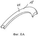
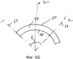
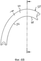
на фиг.6А-фиг.6Ж - различные виды в деталях подающего и месящего сегмента из месильного устройства согласно фиг.1,on figa-fig.6ZH - various views in detail of the feed and curing segment of the kneading device according to figure 1,
на фиг.7 - вид валов в деталях согласно фиг.1, иFig.7 is a view of the shafts in detail according to Fig.1, and
на фиг.8 - вид в деталях месильного устройства согласно изобретению в поперечном сечении.Fig. 8 is a cross-sectional view in detail of a kneading device according to the invention.
Далее имеющие одинаковую функцию элементы месильного устройства, в меру целесообразности, обозначены одинаковыми ссылочными обозначениями. Описанные далее признаки примера осуществления месильного устройства согласно изобретению, само собой разумеется, могут быть предметом изобретения и в других комбинациях.Further, the elements of the kneading device having the same function, to the extent appropriate, are denoted by the same reference signs. The following features of an example implementation of a kneading device according to the invention, of course, can be the subject of the invention in other combinations.
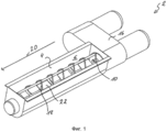
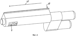
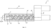
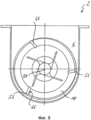
На фиг.1-3 показано месильное устройство 2 согласно изобретению в различных трехмерных изображениях. Месильное устройство 2 содержит частично ограниченную со всех сторон стенкой 4 месильную камеру 6, имеющую изображенное на фиг.2 разгрузочное отверстие 8 для разгрузки замешенного теста из месильной камеры 6, и загрузочную зону 10 для загрузки в месильную камеру 6 подлежащего замешиванию теста, причем загрузочная зона 10 расположена на обращенной от разгрузочного отверстия 8 стороне месильной камеры 6. Месильное устройство 2 содержит также первый вал 12 и второй вал 14, которые в деталях изображены на фиг.4 и 5. Частоты вращения обоих приводимых в действие при помощи мотора валов 12, 14 можно раздельно регулировать и изменять с помощью управляющего устройства 16.Figure 1-3 shows a
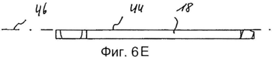
Второй вал 14 оснащен подающими и месящими сегментами 18, которые показаны подающими тесто от загрузочной зоны 10 на обращенной от разгрузочного отверстия 8 стороне месильной камеры 6 в направлении подачи, обозначенном стрелкой 20, к разгрузочному отверстию 8. Под противоположной стороной при этом понимается сторона месильной камеры 6, на которой вал 14 начинает транспортировку подающими и месящими сегментами 18. Загрузочная зона 10 и разгрузочное отверстие 8 расположены, таким образом, с максимальным удалением друг от друга, чтобы иметь возможность обрабатывать тесто на максимальном длинном участке пути в направлении 20 подачи в месильной камере 6.The
Как, прежде всего, видно на фиг.4 и фиг.5, первый вал 12 оснащен в качестве инструментов исключительно лопастями 22, а второй вал 14 оснащен исключительно подающими и месящими сегментами 18. Первый вал 12 и закрепленные на нем лопасти 22 расположены внутри воображаемого цилиндрического кожуха 24, по которому движутся обращенные к первому валу 12 внутренние кромки 26 подающих и месящих сегментов 18 во время вращения вокруг оси 28 второго вала 14. В настоящем примере осуществления ось 28 вращения второго вала 14 идентична оси 30 вращения первого вала 12. Лопасти 22 имеют соответственно лопастную поверхность 32, во время вращения первого вала 12 приводящую в движение находящееся в месильной камере 6 тесто. Как видно, прежде всего, на фиг.3, лопасти 22 расположены вдоль первого вала 12 с взаимным смещением, и траектории движения лопастных поверхностей 32 двух соседних лопастей 22 во время вращения вокруг оси 30 первого вала 12 частично накладываются друг на друга. Каждая лопастная поверхность 32 по меньшей мере на 90%, а в примере осуществления даже полностью, выполнена лежащей в плоскости 34 лопастной поверхности. Кроме того, лопастные поверхности 32 расположены по меньшей мере на 90%, в примере осуществления даже полностью, параллельны оси 30 вращения первого вала 12.As, first of all, it is seen in FIGS. 4 and 5, the
Каждая лопастная поверхность 22 имеет обращенную к подающим и месящим сегментам 18 внешнюю окантовку 36 и расположенную напротив нее внутреннюю замыкающую линию 38. Как показано на фиг.5, исходящий радиально от оси 30 первого вала 12, касательный к внутренней замыкающей линии 38 луч 40 образует с плоскостью 34 лопастной поверхности угол α от 90° до 60°. Касательный к внешней окантовке 36 другой исходящий от оси 30 первого вала 12 луч 42, кроме того, образует с плоскостью 34 лопастной поверхности угол β между 0° и 35°.Each
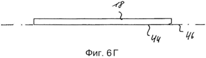
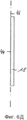
На фиг.4 и фиг.5 показано, что подающие и месящие сегменты 18 соответственно имеют рабочую поверхность 44. Подающие и месящие сегменты 18 расположены вдоль первого вала 14 с взаимным смещением, причем траектории движения рабочих поверхностей 44 двух соседних подающих и месящих сегментов 18 во время вращения вокруг оси 28 второго вала 14 по меньшей мере частично накладываются друг на друга. Рабочая поверхность 44 каждого подающего и месящего сегмента 18 по меньшей мере на 90%, в примере осуществления даже полностью, лежит в плоскости 46 подающего и месящего сегмента. Плоскость 46 подающих и месящих сегментов видна на фиг.6А-фиг.6Ж.Figures 4 and 5 show that the feed and
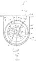
На фиг.5 показан вид в деталях поперечного сечения месильного устройства 2 согласно изобретению. На этом изображении видно, что каждый подающий и месящий сегмент 18 ограничен обращенной к лопастям 22 внутренней окантовкой 48 и противоположной ей, обращенной к стенке 4 месильной камеры 6 внешней окантовкой 50. Обе окантовки 48, 50 выполнены дугообразными таким образом, что подающий и месящий сегмент 18 в проекции на проходящую перпендикулярно оси 28 вращения второго вала 14 плоскость поперечного сечения, которая в примере выполнения соответствует плоскости бумаги, имеет форму сектора окружности с центром окружности и выполненными в форме дуги окружности внутренней и внешней окантовкой 48, 50. Центр окружности при этом идентичен оси 28 вращения второго вала 14. На фиг.6Б вновь показан изолированный подающий и месящий сегмент 18 таким образом, каким он виден в проекции на указанную плоскость поперечного сечения.Figure 5 shows a detail view of a cross section of a
Как видно на фиг.7, рабочие поверхности подающих и месящих сегментов 18 относительно оси 28 вращения второго вала 14 установлены с таким наклоном, что первый угол γ наклона между осью 28 вращения второго вала 14 и первым лучом 52, исходящим в проекции на проходящую перпендикулярно к оси 28 вращения второго вала 14 плоскость поперечного сечения от этой оси 28 вращения и лежащим в плоскости 46 подающего и месящего сегмента на обращенном от разгрузочного отверстия 8 конце подающего и месящего сегмента 18, составляет от 90° до 60°. Другой угол δ наклона между осью 28 вращения второго вала 14 и другим лучом 54, исходящим в проекции на проходящую перпендикулярно к оси 28 вращения второго вала 14 плоскость поперечного сечения от этой оси вращения и лежащим в плоскости 46 подающего и месящего сегмента, составляет от 30° до 75°. При этом первый луч 52 и второй луч 54 в проекции лучей 52, 54 на плоскость поперечного сечения образуют центральный угол ε лучей от 45° до 90°.As can be seen in Fig. 7, the working surfaces of the feeding and kneading
Минимальное расстояние А между лопастями 22 и подающими и месящими сегментами 18 составляет от 1,5 мм до 15,0 мм и, предпочтительно, от 5,0 мм до 10,0 мм, как видно на фиг.5.The minimum distance A between the
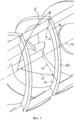
На фиг.4 и фиг.5 видно, что второй вал 14 имеет три расположенных параллельно направлению 20 подачи, находящиеся на равных расстояниях между собой распорки 56, на которых закреплены подающие и месящие сегменты 18. К тому же второй вал 14 имеет первый круглый фиксирующий элемент 58, на котором закреплены распорки 56 второго вала 14. При этом первый вал 12 проходит через выемку 57 первого круглого фиксирующего элемента 58 и не закреплен относительно него. Кроме того, оба вала 12, 14 имеют противоположные направления вращения, показанные на фиг.5 для первого вала 12 круговой стрелкой 62, а для второго вала 14 - другой круговой стрелкой 64. При этом распорки 56 могут быть выполнены круглыми в поперечном сечении для облегчения их очистки. Они могут также иметь обращенную в направлении 64 вращения второго вала 14 к тесту захватывающую поверхность 66, которая в поперечном сечении распорок 56 выполнена плоской, как показано на фиг.8, или имеет изгиб в виде лопатки.Figure 4 and figure 5 shows that the
ССЫЛОЧНЫЕ ОБОЗНАЧЕНИЯREFERENCE NUMBERS
2 месильное устройство2 kneading device
4 стенка4 wall
6 месильная камера6 kneading chamber
8 разгрузочное отверстие8 discharge port
10 загрузочная зона10 boot zone
12 первый вал12 first shaft
14 второй вал14 second shaft
16 управляющее устройство16 control device
18 подающий и месящий сегмент18 feed and month segment
20 направление подачи20 feed direction
22 лопасть22 blade
24 цилиндрический кожух24 cylindrical casing
26 внутренние кромки инструментов второго вала26 inner edges of the tools of the second shaft
28 ось вращения второго вала28 axis of rotation of the second shaft
30 ось вращения первого вала30 axis of rotation of the first shaft
32 лопастная поверхность32 blade surface
34 плоскость лопастной поверхности34 plane of the blade surface
36 внешняя окантовка лопастной поверхности36 outer edging of the blade surface
38 внутренняя замыкающая линия38 internal circuit
40 первый радиальный луч угол α40 first radial beam angle α
42 второй радиальный луч угол β42 second radial beam angle β
44 рабочая поверхность44 work surface
46 плоскость подающего и месящего сегмента46 plane of the giving and cashing segment
48 внутренняя окантовка рабочей поверхности48 inner edging
50 внешняя окантовка рабочей поверхности первый угол γ наклона50 outer fringing of the working surface first inclination angle γ
52 первый луч второй угол δ наклона52 first beam second angle of inclination δ
54 второй луч центральный угол ε лучей54 second ray center angle ε rays
56 распорки56 spacers
57 выемка в первом фиксирующем элементе57 recess in the first locking element
58 первый фиксирующий элемент58 first locking element
62 направление вращения первого вала62 direction of rotation of the first shaft
64 направление вращения второго вала64 direction of rotation of the second shaft
66 захватывающую поверхность66 breathtaking surface
А расстояние между лопастью и подающим и месящим сегментомAnd the distance between the blade and the feed and month segment
Claims (29)
Applications Claiming Priority (3)
| Application Number | Priority Date | Filing Date | Title |
|---|---|---|---|
| DE102010055800.1 | 2010-12-23 | ||
| DE102010055800.1A DE102010055800B4 (en) | 2010-12-23 | 2010-12-23 | kneading |
| PCT/EP2011/005335 WO2012084079A1 (en) | 2010-12-23 | 2011-10-22 | Kneading apparatus for kneading and mixing dough |
Related Child Applications (1)
| Application Number | Title | Priority Date | Filing Date |
|---|---|---|---|
| RU2015151198A Division RU2618123C1 (en) | 2010-12-23 | 2015-11-30 | Kneading device for kneading and stirring dough |
Publications (2)
| Publication Number | Publication Date |
|---|---|
| RU2013134122A RU2013134122A (en) | 2015-01-27 |
| RU2573962C2 true RU2573962C2 (en) | 2016-01-27 |
Family
ID=44936222
Family Applications (2)
| Application Number | Title | Priority Date | Filing Date |
|---|---|---|---|
| RU2013134122/13A RU2573962C2 (en) | 2010-12-23 | 2011-10-22 | Kneading device for dough kneading and stirring |
| RU2015151198A RU2618123C1 (en) | 2010-12-23 | 2015-11-30 | Kneading device for kneading and stirring dough |
Family Applications After (1)
| Application Number | Title | Priority Date | Filing Date |
|---|---|---|---|
| RU2015151198A RU2618123C1 (en) | 2010-12-23 | 2015-11-30 | Kneading device for kneading and stirring dough |
Country Status (10)
| Country | Link |
|---|---|
| US (1) | US9408397B2 (en) |
| EP (1) | EP2654437B1 (en) |
| JP (1) | JP6410425B2 (en) |
| CN (1) | CN103347394B (en) |
| DE (1) | DE102010055800B4 (en) |
| ES (1) | ES2613609T3 (en) |
| PL (1) | PL2654437T3 (en) |
| RU (2) | RU2573962C2 (en) |
| UA (1) | UA112172C2 (en) |
| WO (1) | WO2012084079A1 (en) |
Families Citing this family (1)
| Publication number | Priority date | Publication date | Assignee | Title |
|---|---|---|---|---|
| DE102017123164B3 (en) | 2017-10-05 | 2018-12-27 | Inotec Gmbh Maschinenentwicklung Und Vertrieb | Device for treating a product |
Citations (4)
| Publication number | Priority date | Publication date | Assignee | Title |
|---|---|---|---|---|
| FR2380066A1 (en) * | 1977-02-11 | 1978-09-08 | Creusot Loire | Mixer for continuous mixing of solid powders e.g. cement and clay - has cutting vane passing between helical blades on a shaft, attached to rotating support bars |
| RU2005379C1 (en) * | 1988-11-18 | 1994-01-15 | Бюлер Аг | Kneading device and dough paste production method |
| DE29517612U1 (en) * | 1994-11-16 | 1996-01-11 | Snoek, Michael, Temse | Mixed transport device |
| DE19507181A1 (en) * | 1995-03-02 | 1996-09-05 | Guenter Krueger | Dough mixer assembly with horizontal contra-rotating concentric mixer blades |
Family Cites Families (20)
| Publication number | Priority date | Publication date | Assignee | Title |
|---|---|---|---|---|
| US1660221A (en) * | 1926-05-26 | 1928-02-21 | Robinson Mfg Company | Mixing and crushing machine |
| US2957681A (en) | 1958-03-18 | 1960-10-25 | Ici Ltd | Mixing machines |
| NL283609A (en) * | 1961-10-11 | |||
| US3194504A (en) * | 1962-09-07 | 1965-07-13 | Patterson Ind Inc | Mixing machine |
| DD125478A5 (en) * | 1974-12-11 | 1977-04-20 | ||
| JPS5664750A (en) | 1979-10-30 | 1981-06-02 | Minoru Sekine | Stirring shaft in tea leaf steamer |
| JPS597497B2 (en) | 1980-07-25 | 1984-02-18 | 不二パウダル株式会社 | mixer |
| US4428535A (en) | 1981-07-06 | 1984-01-31 | Liquid Carbonic Corporation | Apparatus to cool particulate matter for grinding |
| JPS6055175B2 (en) | 1982-09-21 | 1985-12-04 | 不二パウダル株式会社 | Mixer/granulator |
| JPS6118813U (en) * | 1984-11-19 | 1986-02-03 | 技術資源開発株式会社 | Continuous concrete mixer |
| US4655701A (en) * | 1986-02-19 | 1987-04-07 | Fuji Paudal Kabushiki Kaisha | Granulating apparatus |
| JPS62259539A (en) * | 1986-05-06 | 1987-11-11 | 株式会社 大竹麺機 | Apparatus for supplying dough to screw extruder for producing food |
| DE3719950A1 (en) * | 1987-06-15 | 1989-01-05 | Agintec Ag | DISPLACEMENT MACHINE |
| DE19636989B4 (en) | 1995-10-27 | 2010-08-26 | Richard Frisse Gmbh | Shearing / mixing tool |
| JPH11179180A (en) | 1997-12-24 | 1999-07-06 | Taiheiyo Kiko Kk | Container fixing type horizontal shaft mixer |
| IT1310181B1 (en) | 1999-03-02 | 2002-02-11 | Map S R L | MIXER DEVICE FOR INCONERENT MATERIAL. |
| FR2814338B1 (en) * | 2000-09-28 | 2005-04-22 | Vmi | HORIZONTAL PETRIN WITH ASYMMETRIC TANK |
| JP4309745B2 (en) * | 2003-11-14 | 2009-08-05 | Jfe環境ソリューションズ株式会社 | Agitating and conveying screw, firing apparatus and firing system using the same |
| AT503036B1 (en) * | 2005-05-25 | 2007-07-15 | Binder Co Ag | Label Remover |
| DE102007011505A1 (en) * | 2007-02-26 | 2008-08-28 | Eglass Machinery & Parts Gmbh | Device homogenizing viscous materials, dispersing striation and streaks, employs stirrer body with vanes designed and arranged to increase stirrer efficiency |
-
2010
- 2010-12-23 DE DE102010055800.1A patent/DE102010055800B4/en not_active Expired - Fee Related
-
2011
- 2011-10-22 UA UAA201309108A patent/UA112172C2/en unknown
- 2011-10-22 US US13/996,620 patent/US9408397B2/en not_active Expired - Fee Related
- 2011-10-22 WO PCT/EP2011/005335 patent/WO2012084079A1/en active Application Filing
- 2011-10-22 PL PL11781744T patent/PL2654437T3/en unknown
- 2011-10-22 RU RU2013134122/13A patent/RU2573962C2/en active
- 2011-10-22 ES ES11781744.5T patent/ES2613609T3/en active Active
- 2011-10-22 JP JP2013545068A patent/JP6410425B2/en not_active Expired - Fee Related
- 2011-10-22 CN CN201180062269.7A patent/CN103347394B/en not_active Expired - Fee Related
- 2011-10-22 EP EP11781744.5A patent/EP2654437B1/en active Active
-
2015
- 2015-11-30 RU RU2015151198A patent/RU2618123C1/en active
Patent Citations (4)
| Publication number | Priority date | Publication date | Assignee | Title |
|---|---|---|---|---|
| FR2380066A1 (en) * | 1977-02-11 | 1978-09-08 | Creusot Loire | Mixer for continuous mixing of solid powders e.g. cement and clay - has cutting vane passing between helical blades on a shaft, attached to rotating support bars |
| RU2005379C1 (en) * | 1988-11-18 | 1994-01-15 | Бюлер Аг | Kneading device and dough paste production method |
| DE29517612U1 (en) * | 1994-11-16 | 1996-01-11 | Snoek, Michael, Temse | Mixed transport device |
| DE19507181A1 (en) * | 1995-03-02 | 1996-09-05 | Guenter Krueger | Dough mixer assembly with horizontal contra-rotating concentric mixer blades |
Also Published As
| Publication number | Publication date |
|---|---|
| RU2013134122A (en) | 2015-01-27 |
| JP2014507125A (en) | 2014-03-27 |
| PL2654437T3 (en) | 2017-04-28 |
| RU2618123C1 (en) | 2017-05-02 |
| EP2654437A1 (en) | 2013-10-30 |
| WO2012084079A1 (en) | 2012-06-28 |
| ES2613609T3 (en) | 2017-05-24 |
| DE102010055800B4 (en) | 2014-12-11 |
| UA112172C2 (en) | 2016-08-10 |
| US9408397B2 (en) | 2016-08-09 |
| EP2654437B1 (en) | 2016-11-16 |
| DE102010055800A1 (en) | 2012-06-28 |
| CN103347394B (en) | 2016-10-19 |
| JP6410425B2 (en) | 2018-10-24 |
| US20130343146A1 (en) | 2013-12-26 |
| CN103347394A (en) | 2013-10-09 |
Similar Documents
| Publication | Publication Date | Title |
|---|---|---|
| JP6661249B2 (en) | Mixer and mixing method | |
| KR102021153B1 (en) | Foreign substance separator | |
| TW474792B (en) | Apparatus for encrusting a filling material | |
| RU2573962C2 (en) | Kneading device for dough kneading and stirring | |
| WO2017018037A1 (en) | Apparatus for heating or cooling starting material | |
| JP2017505228A (en) | Stirring ball mill | |
| KR101237302B1 (en) | raw material crush and gyro screener apparatus | |
| KR20190033157A (en) | Sealing Device for Ratationg Shaft and Machine Appliance having the same | |
| BR112018010914B1 (en) | ROTOR, POLISHING MACHINE AND AIR SUCTION CASING | |
| JP6227736B2 (en) | Kneading equipment | |
| JP2017500200A5 (en) | ||
| CN111989161A (en) | Mixing disk | |
| TW201611954A (en) | Shot blasting apparatus | |
| US3513477A (en) | Apparatus for measuring and feeding food dressing material | |
| JP6081150B2 (en) | Kneading equipment | |
| KR101383778B1 (en) | Paste machine | |
| TWI658859B (en) | Mixing device | |
| RU2553702C1 (en) | Mixer of high-viscosity materials | |
| RU2490876C1 (en) | Metering unit of bulk materials | |
| US144830A (en) | Improvement in machines for the manufacture of flour | |
| RU2601556C1 (en) | Method and device for grinding suspension in opposite rotating streams | |
| RU2533366C1 (en) | Dosing device for bulk materials | |
| RU2678049C1 (en) | Dispenser of bulk materials for preparation of multicomponent mixtures | |
| KR200360881Y1 (en) | Dough mixer screw for food | |
| UA129108U (en) | COMBINED FEED MIXER |