RU2503554C2 - Top-hung door - Google Patents
Top-hung door Download PDFInfo
- Publication number
- RU2503554C2 RU2503554C2 RU2011139535/11A RU2011139535A RU2503554C2 RU 2503554 C2 RU2503554 C2 RU 2503554C2 RU 2011139535/11 A RU2011139535/11 A RU 2011139535/11A RU 2011139535 A RU2011139535 A RU 2011139535A RU 2503554 C2 RU2503554 C2 RU 2503554C2
- Authority
- RU
- Russia
- Prior art keywords
- door
- vehicle body
- vehicle
- opening part
- hinge
- Prior art date
Links
- 238000006243 chemical reaction Methods 0.000 claims abstract description 26
- 238000006073 displacement reaction Methods 0.000 claims description 30
- 239000000725 suspension Substances 0.000 claims description 17
- 230000002093 peripheral effect Effects 0.000 claims description 12
- 238000004904 shortening Methods 0.000 claims description 6
- 230000006835 compression Effects 0.000 claims description 4
- 238000007906 compression Methods 0.000 claims description 4
- 230000008602 contraction Effects 0.000 claims 1
- 230000000694 effects Effects 0.000 abstract description 9
- 239000000126 substance Substances 0.000 abstract 1
- 230000014759 maintenance of location Effects 0.000 description 17
- 230000000052 comparative effect Effects 0.000 description 10
- 239000000853 adhesive Substances 0.000 description 5
- 230000001070 adhesive effect Effects 0.000 description 5
- 238000010276 construction Methods 0.000 description 4
- 238000009434 installation Methods 0.000 description 4
- 239000002184 metal Substances 0.000 description 3
- 230000003014 reinforcing effect Effects 0.000 description 3
- 230000005489 elastic deformation Effects 0.000 description 2
- 239000005357 flat glass Substances 0.000 description 2
- 229920002635 polyurethane Polymers 0.000 description 2
- 239000004814 polyurethane Substances 0.000 description 2
- JOYRKODLDBILNP-UHFFFAOYSA-N Ethyl urethane Chemical compound CCOC(N)=O JOYRKODLDBILNP-UHFFFAOYSA-N 0.000 description 1
- 241000272168 Laridae Species 0.000 description 1
- 230000009286 beneficial effect Effects 0.000 description 1
- 229920001971 elastomer Polymers 0.000 description 1
- 239000007788 liquid Substances 0.000 description 1
- 239000000463 material Substances 0.000 description 1
- 239000007769 metal material Substances 0.000 description 1
- 238000011084 recovery Methods 0.000 description 1
- 230000001105 regulatory effect Effects 0.000 description 1
- 239000005060 rubber Substances 0.000 description 1
- 239000007779 soft material Substances 0.000 description 1
- 230000002269 spontaneous effect Effects 0.000 description 1
- 230000001629 suppression Effects 0.000 description 1
- 229920003051 synthetic elastomer Polymers 0.000 description 1
- 229920003002 synthetic resin Polymers 0.000 description 1
- 239000000057 synthetic resin Substances 0.000 description 1
- 239000005061 synthetic rubber Substances 0.000 description 1
Images


Classifications
-
- B—PERFORMING OPERATIONS; TRANSPORTING
- B60—VEHICLES IN GENERAL
- B60J—WINDOWS, WINDSCREENS, NON-FIXED ROOFS, DOORS, OR SIMILAR DEVICES FOR VEHICLES; REMOVABLE EXTERNAL PROTECTIVE COVERINGS SPECIALLY ADAPTED FOR VEHICLES
- B60J5/00—Doors
- B60J5/10—Doors arranged at the vehicle rear
- B60J5/101—Doors arranged at the vehicle rear for non-load transporting vehicles, i.e. family cars including vans
-
- E—FIXED CONSTRUCTIONS
- E05—LOCKS; KEYS; WINDOW OR DOOR FITTINGS; SAFES
- E05D—HINGES OR SUSPENSION DEVICES FOR DOORS, WINDOWS OR WINGS
- E05D5/00—Construction of single parts, e.g. the parts for attachment
- E05D5/02—Parts for attachment, e.g. flaps
- E05D5/04—Flat flaps
- E05D5/043—Flat flaps specially adapted for vehicles
-
- E—FIXED CONSTRUCTIONS
- E05—LOCKS; KEYS; WINDOW OR DOOR FITTINGS; SAFES
- E05F—DEVICES FOR MOVING WINGS INTO OPEN OR CLOSED POSITION; CHECKS FOR WINGS; WING FITTINGS NOT OTHERWISE PROVIDED FOR, CONCERNED WITH THE FUNCTIONING OF THE WING
- E05F1/00—Closers or openers for wings, not otherwise provided for in this subclass
- E05F1/08—Closers or openers for wings, not otherwise provided for in this subclass spring-actuated, e.g. for horizontally sliding wings
- E05F1/10—Closers or openers for wings, not otherwise provided for in this subclass spring-actuated, e.g. for horizontally sliding wings for swinging wings, e.g. counterbalance
- E05F1/1091—Closers or openers for wings, not otherwise provided for in this subclass spring-actuated, e.g. for horizontally sliding wings for swinging wings, e.g. counterbalance with a gas spring
-
- E—FIXED CONSTRUCTIONS
- E05—LOCKS; KEYS; WINDOW OR DOOR FITTINGS; SAFES
- E05D—HINGES OR SUSPENSION DEVICES FOR DOORS, WINDOWS OR WINGS
- E05D5/00—Construction of single parts, e.g. the parts for attachment
- E05D5/02—Parts for attachment, e.g. flaps
- E05D5/06—Bent flaps
- E05D5/062—Bent flaps specially adapted for vehicles
-
- E—FIXED CONSTRUCTIONS
- E05—LOCKS; KEYS; WINDOW OR DOOR FITTINGS; SAFES
- E05F—DEVICES FOR MOVING WINGS INTO OPEN OR CLOSED POSITION; CHECKS FOR WINGS; WING FITTINGS NOT OTHERWISE PROVIDED FOR, CONCERNED WITH THE FUNCTIONING OF THE WING
- E05F5/00—Braking devices, e.g. checks; Stops; Buffers
- E05F5/02—Braking devices, e.g. checks; Stops; Buffers specially for preventing the slamming of swinging wings during final closing movement, e.g. jamb stops
- E05F5/022—Braking devices, e.g. checks; Stops; Buffers specially for preventing the slamming of swinging wings during final closing movement, e.g. jamb stops specially adapted for vehicles, e.g. for hoods or trunks
-
- E—FIXED CONSTRUCTIONS
- E05—LOCKS; KEYS; WINDOW OR DOOR FITTINGS; SAFES
- E05Y—INDEXING SCHEME ASSOCIATED WITH SUBCLASSES E05D AND E05F, RELATING TO CONSTRUCTION ELEMENTS, ELECTRIC CONTROL, POWER SUPPLY, POWER SIGNAL OR TRANSMISSION, USER INTERFACES, MOUNTING OR COUPLING, DETAILS, ACCESSORIES, AUXILIARY OPERATIONS NOT OTHERWISE PROVIDED FOR, APPLICATION THEREOF
- E05Y2201/00—Constructional elements; Accessories therefor
- E05Y2201/40—Motors; Magnets; Springs; Weights; Accessories therefor
- E05Y2201/404—Function thereof
- E05Y2201/416—Function thereof for counterbalancing
-
- E—FIXED CONSTRUCTIONS
- E05—LOCKS; KEYS; WINDOW OR DOOR FITTINGS; SAFES
- E05Y—INDEXING SCHEME ASSOCIATED WITH SUBCLASSES E05D AND E05F, RELATING TO CONSTRUCTION ELEMENTS, ELECTRIC CONTROL, POWER SUPPLY, POWER SIGNAL OR TRANSMISSION, USER INTERFACES, MOUNTING OR COUPLING, DETAILS, ACCESSORIES, AUXILIARY OPERATIONS NOT OTHERWISE PROVIDED FOR, APPLICATION THEREOF
- E05Y2900/00—Application of doors, windows, wings or fittings thereof
- E05Y2900/50—Application of doors, windows, wings or fittings thereof for vehicles
- E05Y2900/53—Type of wing
- E05Y2900/546—Tailboards, tailgates or sideboards opening upwards
Landscapes
- Engineering & Computer Science (AREA)
- Mechanical Engineering (AREA)
- Body Structure For Vehicles (AREA)
- Closing And Opening Devices For Wings, And Checks For Wings (AREA)
Abstract
Description
Область техникиTechnical field
Настоящее изобретение относится к верхнеподвесной конструкции двери, поддерживающей дверь, которая открывает и закрывает открывающуюся часть кузова транспортного средства, с помощью шарниров, обеспеченных на верхней стороне открывающейся части.The present invention relates to a top-hung door structure supporting a door that opens and closes an opening portion of a vehicle body using hinges provided on the upper side of the opening portion.
Уровень техникиState of the art
Известно множество различных приспособлений, таких как, например, приспособления, выполняющие операцию плавного открывания/закрывания и т.п. для задних дверей (см., например, публикации выложенных заявок на патент Японии (JP-A) №2007-245747, JP-A №9-220934, JP-A 2003-291645, JP-A №11-350827 и JP-A №8-324255).Many different devices are known, such as, for example, devices that perform a smooth opening / closing operation and the like. for rear doors (see, for example, Japanese Patent Laid-Open Publication (JP-A) No. 2007-245747, JP-A No. 9-220934, JP-A 2003-291645, JP-A No. 11-350827 and JP- A No. 8-324255).
Проблемы, на решение которых направлено изобретениеProblems to be Solved by the Invention
Что касается задней двери, поддерживаемой на кузове транспортного средства посредством шарниров, размещенных на верхней стороне открывающейся части кузова транспортного средства, то, когда такой элемент, как демпфер или т.п., для поддерживания двери в полностью открытом положении обеспечен только с одной концевой стороны в горизонтальном направлении кузова транспортного средства, имеется возможность улучшения подгонки двери.As for the rear door supported on the vehicle body by means of hinges placed on the upper side of the opening part of the vehicle body, when such an element as a damper or the like is provided for supporting the door in a fully open position from only one end side in the horizontal direction of the vehicle body, it is possible to improve the fit of the door.
Задачей настоящего изобретения является создание в конструкции, где механизм удержания двери для поддерживания двери в полностью открытом положении предусмотрен только с одной концевой стороны в горизонтальном направлении, верхнеподвесной конструкции двери, которая может обеспечить правильную установку двери на кузове транспортного средства.It is an object of the present invention to provide, in a structure where a door holding mechanism for supporting a door in a fully open position, is provided on only one end side in a horizontal direction, a top-hung door structure that can ensure proper installation of the door on a vehicle body.
Средство решения проблемProblem Solver
Верхнеподвесная конструкция двери согласно первому аспекту настоящего изобретения имеет: пару шарниров, обеспеченных на кузове транспортного средства так, что они отстоят друг от друга в горизонтальном направлении и находятся на верхней стороне в вертикальном направлении транспортного средства по отношению к открывающейся части, сформированной в кузове транспортного средства; дверь, которая поддерживается в кузове транспортного средства парой шарниров и которая открывает и закрывает открывающуюся часть путем поворота относительно осей шарниров, являющихся осями вращения; механизм удержания двери, обеспеченный между дверью и кузовом транспортного средства с одной концевой стороны двери в горизонтальном направлении, который создает силу сопротивления, преодолевающую собственный вес двери, и поддерживает положение, в котором дверь полностью открывает открывающуюся часть, и который из-за нагрузки, превышающей силу сопротивления, позволяет двери перемещаться в направлении закрывания открывающейся части; и конструкцию для поддерживания двери, которая выполнена так, что в состоянии, когда дверь не поддерживается, ось одного шарнира, расположенного на стороне, где установлен механизм удержания двери между парой шарниров, расположена дальше в направлении верхней стороны в вертикальном направлении транспортного средства, чем ось другого шарнира.The upper hinged door structure according to the first aspect of the present invention has: a pair of hinges provided on the vehicle body so that they are spaced apart from each other in the horizontal direction and are on the upper side in the vertical direction of the vehicle with respect to an opening portion formed in the vehicle body ; a door that is supported in the vehicle body by a pair of hinges and which opens and closes the opening part by rotation about the hinge axes, which are rotation axes; a door holding mechanism provided between the door and the vehicle body at one end of the door in the horizontal direction, which creates a resistance force that overcomes the own weight of the door and maintains a position in which the door completely opens the opening part, and which due to a load exceeding resistance force, allows the door to move in the direction of closing the opening part; and a structure for supporting the door, which is designed so that in a state where the door is not supported, the axis of one hinge located on the side where the door holding mechanism is installed between the pair of hinges is located further in the direction of the upper side in the vertical direction of the vehicle than the axis another hinge.
Согласно вышеописанному аспекту, что касается двери, которая поворачивается относительно осей шарниров как осей вращения и открывает и закрывает открывающуюся часть кузова транспортного средства, то положение полного открытия открывающейся части поддерживается механизмом удержания двери, преодолевающим ее собственный вес. Когда к двери в направлении закрывания (в направлении нижней части транспортного средства) приложена нагрузка заранее определенного или большего значения, которая превышает указанную силу сопротивления, дверь достигает положения закрывания открывающейся части, преодолевая силу сопротивления механизма удержания двери.According to the above-described aspect, with regard to a door that rotates relative to the hinge axes as rotational axes and opens and closes the opening part of the vehicle body, the full opening position of the opening part is supported by the door holding mechanism, overcoming its own weight. When a load of a predetermined or greater value that exceeds the specified resistance force is applied to the door in the closing direction (towards the bottom of the vehicle), the door reaches the closing position of the opening part, overcoming the resistance force of the door holding mechanism.
Впрочем, в конструкции, где механизм удержания двери обеспечен только с одной концевой стороны в горизонтальном направлении между кузовом транспортного средства и дверью, из-за силы реакции механизма удержания двери дверь легко поворачивается относительно кузова транспортного средства, так что часть со стороны, где установлен механизм удержания двери, располагается с нижней стороны в вертикальном направлении транспортного средства по отношению к противоположной стороне.However, in a design where the door retention mechanism is provided on only one end side in a horizontal direction between the vehicle body and the door, due to the reaction force of the door retention mechanism, the door is easily rotated relative to the vehicle body, so that the part from the side where the mechanism is installed door holding, located on the bottom side in the vertical direction of the vehicle relative to the opposite side.
Здесь в конструкции для поддерживания двери, которая обеспечивает верхнеподвесную конструкцию двери согласно вышеописанному аспекту, в состоянии, когда дверь не поддерживается, шарнир, расположенный на стороне, где между парой шарниров установлен механизм удержания двери, расположен дальше в направлении верхней стороны в вертикальном направлении транспортного средства, чем другой шарнир. Таким образом, даже в том случае, если дверь поворачивается, как было описано выше, позиционное смещение в вертикальном направлении транспортного средства может поддерживаться малым в части с той стороны, где на двери установлен механизм удержания двери, и с противоположной стороны.Herein, in a door support structure that provides a top-hung door structure according to the above-described aspect, in a state where the door is not supported, a hinge located on a side where a door holding mechanism is installed between the pair of hinges is located further towards the upper side in the vehicle vertical direction than another hinge. Thus, even if the door is rotated, as described above, the positional displacement in the vertical direction of the vehicle can be kept small in part from the side where the door retention mechanism is installed on the door, and from the opposite side.
Таким путем в конструкции, относящейся к вышеописанному аспекту, может быть обеспечена правильная установка двери на кузове транспортного средства с использованием конструкции, где механизм удержания двери для поддерживания двери в полностью открытом положении обеспечен только с одной концевой стороны в горизонтальном направлении.In this way, in a structure related to the above aspect, a door can be correctly mounted on the vehicle body using a structure where the door holding mechanism for supporting the door in a fully open position is provided from only one end side in a horizontal direction.
Согласно вышеописанному аспекту конструкция для поддерживания двери может быть выполнена так, что в состоянии, когда дверь не поддерживается, монтажная поверхность, на которой смонтирован шарнир на кузове транспортного средства, располагается дальше в направлении верхней стороны в вертикальном направлении транспортного средства со стороны одного шарнира, которая расположена со стороны, где установлена конструкция для удержания двери, чем со стороны другого шарнира.According to the above-described aspect, the structure for supporting the door can be configured such that in a state where the door is not supported, the mounting surface on which the hinge is mounted on the vehicle body is located further in the direction of the upper side in the vertical direction of the vehicle from the side of one hinge, which located on the side where the structure for holding the door is installed, than on the side of the other hinge.
Согласно вышеописанному аспекту при использовании вместе пары шарниров позиционное смещение в вертикальном направлении транспортного средства может поддерживаться малым в части со стороны, где на двери установлен механизм удержания двери, и с противоположной стороны. Кроме того, из-за вышеописанного поворота двери относительно кузова транспортного средства, происходит упругая деформация кузова транспортного средства вблизи монтажных поверхностей шарниров в направлении нижней стороны, причем более сильная на той стороне, где установлен механизм удержания двери, чем на противоположной стороне.According to the above aspect, when using a pair of hinges together, the positional displacement in the vertical direction of the vehicle can be kept small in part from the side where the door retention mechanism is mounted on the door, and from the opposite side. In addition, due to the above-described rotation of the door relative to the vehicle body, elastic deformation of the vehicle body occurs near the mounting surfaces of the hinges in the direction of the lower side, more severe on the side where the door holding mechanism is installed than on the opposite side.
Таким образом, поддерживающая сила реакции с той стороны, где установлен механизм удержания двери, будет больше, чем с противоположной стороны. Благодаря этому не допускается вышеописанный самопроизвольный поворот двери относительно кузова транспортного средства.Thus, the supporting reaction force from the side where the door retention mechanism is installed will be greater than from the opposite side. Due to this, the above-described spontaneous rotation of the door relative to the vehicle body is not allowed.
Верхнеподвесная конструкция двери, связанная со вторым аспектом настоящего изобретения имеет: пару шарниров, обеспеченных на кузове транспортного средства так, что они отстоят друг от друга в горизонтальном направлении и находятся на верхней стороне в вертикальном направлении транспортного средства по отношению к открывающейся части, сформированной в кузове транспортного средства; дверь, которая поддерживается в кузове транспортного средства парой шарниров и которая открывает и закрывает открывающуюся часть путем поворота относительно осей шарниров, являющихся осями вращения; механизм удержания двери, обеспеченный между дверью и кузовом транспортного средства с одной концевой стороны двери в горизонтальном направлении, который создает силу сопротивления, преодолевающую собственный вес двери, и поддерживает положение, в котором дверь полностью открывает открывающуюся часть, и который из-за нагрузки, превышающей силу сопротивления, позволяет двери перемещаться в направлении закрывания открывающейся части; и конструкцию для поддерживания двери, которая выполнена так, что поддерживающая сила реакции, в вертикальном направлении транспортного средства, монтажной части одного шарнира, расположенного на стороне, где установлен механизм удержания двери между парой шарниров, превышает поддерживающую силу реакции, в вертикальном направлении транспортного средства, монтажной части другого шарнира.The top-hung door structure associated with the second aspect of the present invention has: a pair of hinges provided on the vehicle body so that they are spaced apart from each other in the horizontal direction and are on the upper side in the vertical direction of the vehicle with respect to an opening portion formed in the body vehicle; a door that is supported in the vehicle body by a pair of hinges and which opens and closes the opening part by rotation about the hinge axes, which are rotation axes; a door holding mechanism provided between the door and the vehicle body at one end of the door in the horizontal direction, which creates a resistance force that overcomes the own weight of the door and maintains a position in which the door completely opens the opening part, and which due to a load exceeding resistance force, allows the door to move in the direction of closing the opening part; and a structure for supporting the door, which is designed so that the supporting reaction force in the vertical direction of the vehicle, the mounting part of one hinge located on the side where the door holding mechanism is installed between the pair of hinges, exceeds the supporting reaction force in the vertical direction of the vehicle, mounting part of another hinge.
Согласно вышеописанному аспекту, что касается двери, которая поворачивается относительно осей шарниров как осей вращения и открывает и закрывает открывающуюся часть кузова транспортного средства, то положение полного открытия открывающейся части поддерживается механизмом удержания двери, преодолевающим собственный вес. Когда к двери в направлении закрывания, в направлении нижней части транспортного средства, приложена нагрузка заранее определенного или большего значения, которая превышает указанную силу сопротивления, дверь достигает положения закрывания открывающейся части, преодолевая силу сопротивления механизма удержания двери.According to the above-described aspect, with regard to a door that rotates relative to the hinge axes as rotational axes and opens and closes the opening part of the vehicle body, the full opening position of the opening part is supported by the door holding mechanism that overcomes its own weight. When a load of a predetermined or greater value that exceeds the specified resistance force is applied to the door in the closing direction, in the direction of the lower part of the vehicle, the door reaches the closing position of the opening part, overcoming the resistance force of the door holding mechanism.
Впрочем, в конструкции, где механизм удержания двери обеспечен только с одной концевой стороны в горизонтальном направлении между кузовом транспортного средства и дверью, из-за силы реакции механизма удержания двери дверь легко поворачивается относительно кузова транспортного средства, так что часть со стороны, где установлен механизм удержания двери, располагается с нижней стороны в вертикальном направлении транспортного средства по отношению к противоположной стороне.However, in a design where the door retention mechanism is provided on only one end side in a horizontal direction between the vehicle body and the door, due to the reaction force of the door retention mechanism, the door is easily rotated relative to the vehicle body, so that the part from the side where the mechanism is installed door holding, located on the bottom side in the vertical direction of the vehicle relative to the opposite side.
Здесь в конструкции для поддерживания двери, которая обеспечивает верхнеподвесную конструкцию двери согласно вышеописанному аспекту, в монтажной части шарнира, которая расположена со стороны, где установлен механизм удержания двери между парой шарниров, поддерживающая сила реакции в вертикальном направлении транспортного средства сделана большей, чем в монтажной части другого шарнира. Таким образом, на стороне, где установлен механизм удержания двери, затруднено смещение двери в направлении нижней стороны в вертикальном направлении транспортного средства из-за силы реакции механизма удержания двери. То есть не допускается вышеописанный поворот двери относительно кузова транспортного средства, вызываемый механизмом удержания двери, обеспеченным только с одной концевой стороны.Here, in the structure for supporting the door, which provides the upper suspension door structure according to the above aspect, in the mounting part of the hinge, which is located on the side where the door holding mechanism is installed between the pair of hinges, the supporting reaction force in the vertical direction of the vehicle is made larger than in the mounting part another hinge. Thus, on the side where the door holding mechanism is installed, it is difficult to move the door toward the lower side in the vertical direction of the vehicle due to the reaction force of the door holding mechanism. That is, the above-described rotation of the door relative to the vehicle body caused by the door holding mechanism provided from only one end side is not allowed.
Таким путем в конструкции, относящейся к вышеописанному аспекту, может быть обеспечена правильная установка двери на кузове транспортного средства с использованием конструкции, где механизм удержания двери для поддерживания двери в полностью открытом положении обеспечен только с одной концевой стороны в горизонтальном направлении.In this way, in a structure related to the above aspect, a door can be correctly mounted on the vehicle body using a structure where the door holding mechanism for supporting the door in a fully open position is provided from only one end side in a horizontal direction.
Согласно вышеописанному аспекту конструкция для поддерживания двери может быть выполнена так, что в состоянии, когда дверь не поддерживается, монтажная поверхность, на которой смонтирован шарнир на кузове транспортного средства, располагается дальше в направлении верхней стороны в вертикальном направлении транспортного средства со стороны одного шарнира, которая расположена со стороны, где установлена конструкция для удержания двери, чем со стороны другого шарнира.According to the above-described aspect, the structure for supporting the door can be configured such that in a state where the door is not supported, the mounting surface on which the hinge is mounted on the vehicle body is located further in the direction of the upper side in the vertical direction of the vehicle from the side of one hinge, which located on the side where the structure for holding the door is installed, than on the side of the other hinge.
Согласно вышеописанному аспекту монтажная поверхность шарнира на кузове транспортного средства расположена дальше в направлении верхней стороны в вертикальном направлении транспортного средства со стороны, где установлен механизм удержания двери, чем с противоположной стороны. Другими словами, величина смещения (хода) верхней концевой части двери из-за вышеописанного поворота двери относительно кузова транспортного средства сделана большей со стороны, где установлен механизм удержания двери, чем с противоположной стороны. Из-за этого кузов транспортного средства упруго деформируется в направлении нижней стороны более сильно с той стороны, где установлен механизм удержания двери, чем с противоположной стороны, и, следовательно, поддерживающая сила реакции двери оказывается большей со стороны, где установлен механизм удержания двери, чем с противоположной стороны. Кроме того, поскольку сторона, на которой установлен механизм удержания двери, расположена с верхней стороны, может поддерживаться малое позиционное смещение в вертикальном направлении транспортного средства у части на стороне, где у двери установлен механизм удержания двери, и на противоположной стороне.According to the above-described aspect, the mounting surface of the hinge on the vehicle body is located further in the direction of the upper side in the vertical direction of the vehicle from the side where the door holding mechanism is installed than from the opposite side. In other words, the displacement (stroke) of the upper end of the door due to the above-described rotation of the door relative to the vehicle body is made larger on the side where the door holding mechanism is installed than on the opposite side. Because of this, the vehicle body is elastically deformed in the direction of the lower side more strongly from the side where the door holding mechanism is installed than from the opposite side, and therefore, the supporting reaction force of the door is greater from the side where the door holding mechanism is installed than from the opposite side. In addition, since the side on which the door retention mechanism is mounted is located on the upper side, a small positional displacement in the vertical direction of the vehicle can be maintained at the part on the side where the door retention mechanism is installed at the door and on the opposite side.
Согласно вышеописанному аспекту возможна конструкция, в которой соответствующие монтажные поверхности являются поверхностями, которые обращены к верхней стороне в вертикальном направлении транспортного средства, и где пара шарниров закреплена на кузове транспортного средства болтами, которые проходят в вертикальном направлении транспортного средства сквозь панель кузова транспортного средства, имеющую монтажные поверхности.According to the above-described aspect, a structure is possible in which the respective mounting surfaces are surfaces that face the upper side in the vertical direction of the vehicle, and where a pair of hinges are fixed to the vehicle body with bolts that extend in the vertical direction of the vehicle through the vehicle body panel having mounting surfaces.
Согласно вышеописанному аспекту шарниры закреплены на монтажных поверхностях кузова транспортного средства силой зажима в вертикальном направлении транспортного средства благодаря болтам. В этой конструкции кузов транспортного средства (листовой металл) легко подвергается упругой деформации в вертикальном направлении транспортного средства (направление толщины пластины), и, следовательно, благодаря тому, что монтажная поверхность находится дальше в направлении верхней стороны в вертикальном направлении транспортного средства со стороны, где установлен механизм удержания двери, чем с противоположной стороны, облегчается правильная установка двери в кузов транспортного средства.According to the above aspect, the hinges are fixed to the mounting surfaces of the vehicle body by a clamping force in the vertical direction of the vehicle due to bolts. In this design, the vehicle body (sheet metal) easily undergoes elastic deformation in the vertical direction of the vehicle (direction of plate thickness), and therefore, due to the fact that the mounting surface is further in the direction of the upper side in the vertical direction of the vehicle from the side where a door retention mechanism is installed than on the opposite side, the correct installation of the door in the vehicle body is facilitated.
Согласно вышеописанному аспекту верхнеподвесная конструкция двери может представлять собой конструкцию, дополнительно имеющую регулировочный элемент, который обеспечен между кузовом транспортного средства и частью с противоположной стороны в горизонтальном направлении стороны, где установлен механизм удержания двери, у нижней части двери в вертикальном направлении транспортного средства, и который регулирует дверь, находящуюся в положении закрывания открывающейся части, и смещаемую в направлении закрывания открывающейся части относительно кузова транспортного средства.According to the above-described aspect, the top-hung door structure may be a structure further having an adjustment element which is provided between the vehicle body and the part on the opposite side in the horizontal direction of the side where the door holding mechanism is installed at the bottom of the door in the vertical direction of the vehicle, and which adjusts the door in the closing position of the opening part, and shifted in the closing direction of the opening part about in relative to the vehicle body.
В конструкции, где механизм удержания двери обеспечен у двери только с одной концевой стороны в горизонтальном направлении, из-за силы реакции механизма удержания двери дверь легко отклоняется относительно кузова транспортного средства, так что часть со стороны, где у двери установлен механизм удержания двери, выталкивается в направлении внешней стороны транспортного средства относительно противоположной стороны.In a design where the door retention mechanism is provided at the door with only one end side in the horizontal direction, due to the reaction force of the door retention mechanism, the door is easily deflected relative to the vehicle body, so that the part from the side where the door retention mechanism is installed at the door is ejected towards the outside of the vehicle relative to the opposite side.
Здесь согласно вышеописанному аспекту смещение двери в направлении стороны кузова транспортного средства, которая находится в положении закрывания открывающейся части, регулируется (дверь воспринимает регулировочное усилие) регулировочным элементом в части, находящейся на противоположной стороне, в горизонтальном направлении и вертикальном направлении относительно части, к которой прикладывается сила реакции от механизма удержания двери. Следовательно, момент, преодолевающий вышеописанный наклон двери, возрастает из-за регулировочного усилия со стороны регулировочного элемента, в связи с чем не допускается наклон двери.Here, according to the above-described aspect, the displacement of the door in the direction of the side of the vehicle body, which is in the closing position of the opening part, is regulated (the door receives an adjustment force) by the adjustment element in the part located on the opposite side, in the horizontal direction and the vertical direction relative to the part to which is applied reaction force from the door holding mechanism. Therefore, the moment that overcomes the above-described inclination of the door increases due to the adjusting force on the part of the adjusting element, and therefore the inclination of the door is not allowed.
Верхнеподвесная конструкция двери, связанная с третьим аспектом настоящего изобретения имеет: пару шарниров, обеспеченных на кузове транспортного средства, так что они отстоят друг от друга в горизонтальном направлении и находятся на верхней стороне в вертикальном направлении транспортного средства по отношению к открывающейся части, сформированной в кузове транспортного средства; дверь, которая поддерживается в кузове транспортного средства парой шарниров и которая открывает и закрывает открывающуюся часть путем поворота относительно осей шарниров, являющихся осями вращения; механизм удержания двери, обеспеченный между дверью и кузовом транспортного средства с одной концевой стороны двери в горизонтальном направлении, который создает силу сопротивления, преодолевающую собственный вес двери, и поддерживает положение, в котором дверь полностью открывает открывающуюся часть, и который из-за нагрузки, превышающей силу сопротивления, позволяет двери перемещаться в направлении закрывания открывающейся части; и регулировочный элемент, обеспеченный между кузовом транспортного средства и частью на противоположной стороне в горизонтальном направлении стороны, где установлен механизм удержания двери, у нижней части двери в вертикальном направлении транспортного средства и который регулирует дверь, находящуюся в положении закрывания открывающейся части, смещаемой в направлении закрывания открывающейся части относительно кузова транспортного средства.The top-hung door structure associated with the third aspect of the present invention has: a pair of hinges provided on the vehicle body so that they are spaced apart in the horizontal direction and are on the upper side in the vertical direction of the vehicle with respect to an opening portion formed in the body vehicle; a door that is supported in the vehicle body by a pair of hinges and which opens and closes the opening part by rotation about the hinge axes, which are rotation axes; a door holding mechanism provided between the door and the vehicle body at one end of the door in the horizontal direction, which creates a resistance force that overcomes the own weight of the door and maintains a position in which the door completely opens the opening part, and which due to a load exceeding resistance force, allows the door to move in the direction of closing the opening part; and an adjustment element provided between the vehicle body and the part on the opposite side in the horizontal direction of the side where the door holding mechanism is installed, at the bottom of the door in the vertical direction of the vehicle and which adjusts the door in the closing position of the opening part that is shifted in the closing direction opening part relative to the vehicle body.
Согласно вышеописанному аспекту, что касается двери, которая поворачивается относительно осей шарниров как осей вращения и открывает и закрывает открывающуюся часть кузова транспортного средства, то положение полного открытия открывающейся части поддерживается механизмом удержания двери, преодолевающим собственный вес. Когда к двери в направлении закрывания (в направлении нижней части транспортного средства) приложена нагрузка заранее определенного или большего значения, которая превышает указанную силу сопротивления, дверь достигает положения закрывания открывающейся части, преодолевая силу сопротивления механизма удержания двери.According to the above-described aspect, with regard to a door that rotates relative to the hinge axes as rotational axes and opens and closes the opening part of the vehicle body, the full opening position of the opening part is supported by the door holding mechanism that overcomes its own weight. When a load of a predetermined or greater value that exceeds the specified resistance force is applied to the door in the closing direction (towards the bottom of the vehicle), the door reaches the closing position of the opening part, overcoming the resistance force of the door holding mechanism.
Впрочем, в конструкции, где механизм удержания двери обеспечен у двери только с одной концевой стороны в горизонтальном направлении, из-за силы реакции механизма удержания двери дверь легко отклоняется относительно кузова транспортного средства, так что часть на стороне, где у двери установлен механизм удержания двери, выталкивается в направлении внешней стороны транспортного средства относительно противоположной стороны.However, in a design where the door retention mechanism is provided at the door with only one end side in the horizontal direction, due to the reaction force of the door retention mechanism, the door is easily deflected relative to the vehicle body, so that the part on the side where the door retention mechanism is installed at the door pushed towards the outside of the vehicle relative to the opposite side.
Здесь в верхнеподвесной конструкции двери согласно вышеописанному аспекту на противоположной стороне стороны, где между кузовом транспортного средства и дверью установлен механизм удержания двери, установлен ограничительный элемент. Таким образом, регулируется смещение (в направлении стороны кузова транспортного средства) двери, находящейся в положении закрывания открывающейся части (дверь воспринимает регулировочное усилие) с помощью регулировочного элемента в части, находящейся у противоположной стороны, в горизонтальном направлении и вертикальном направлении относительно части, к которой приложена сила реакции от механизма удержания двери. Следовательно, момент, преодолевающий вышеописанный наклон двери относительно кузова транспортного средства, увеличивается из-за силы сопротивления регулировочного элемента, в связи с чем не допускается наклон двери.Here, in the upper suspension door structure according to the above-described aspect, on the opposite side of the side where the door holding mechanism is installed between the vehicle body and the door, a restriction member is installed. Thus, the displacement (in the direction of the side of the vehicle body) of the door in the closing position of the opening part (the door takes up the adjusting force) is controlled by the adjustment element in the part located on the opposite side in the horizontal direction and the vertical direction relative to the part to which reaction force is applied from the door holding mechanism. Therefore, the moment, overcoming the above-described inclination of the door relative to the vehicle body, increases due to the resistance force of the adjusting element, and therefore the inclination of the door is not allowed.
Таким путем в конструкции, относящейся к вышеописанному аспекту, может быть обеспечена правильная установка двери в кузов транспортного средства при использовании конструкции, где механизм удержания двери для поддерживания двери в полностью открытом положении обеспечен только с одной концевой стороны в горизонтальном направлении.In this way, in a structure related to the above aspect, the door can be correctly installed in the vehicle body using a structure where the door holding mechanism for supporting the door in a fully open position is provided from only one end side in the horizontal direction.
Согласно вышеописанному аспекту регулировочный элемент может иметь конструкцию, которая в состоянии, когда дверь закрывает открывающуюся часть, смещается, упруго сжимаясь между дверью и кузовом транспортного средства.According to the above-described aspect, the adjusting element may have a structure which, when the door closes the opening part, is displaced, elastically contracting between the door and the vehicle body.
Согласно вышеописанному аспекту в положении закрывания открывающейся части дверь всегда контактирует с регулировочным элементом и оказывается в состоянии упругого сжатия между регулировочным элементом и кузовом транспортного средства. Следовательно, чем большим становится вышеописанный наклон двери, тем большим становится регулировочное усилие, препятствующее этому наклону. Кроме того, не допускается относительное смещение (например, дребезжания или т.п.) двери относительно кузова транспортного средства.According to the above aspect, in the closing position of the opening part, the door is always in contact with the adjusting element and is in a state of elastic compression between the adjusting element and the vehicle body. Therefore, the greater the above-described inclination of the door becomes, the greater becomes the adjusting force that prevents this inclination. In addition, the relative displacement (for example, rattles or the like) of the door relative to the vehicle body is not allowed.
Согласно вышеописанному аспекту возможна конструкция, в которой дверь имеет оконную часть, причем, по меньшей мере, часть периферийной краевой части оконной части усилена в отношении нагрузки в вертикальном направлении транспортного средства. Согласно вышеописанному аспекту повышается жесткость двери в вертикальном направлении, где усилена периферийная краевая часть оконной части. Таким образом, из-за силы реакции механизма удержания двери, который обеспечен только с одной стороны открывающейся части в поперечном направлении, не допускается самодеформация двери в вертикальном направлении транспортного средства, и поддерживается малая величина позиционного смещения в вертикальном направлении транспортного средства в части на стороне, где установлен механизм удержания двери, и на противоположной стороне.According to the above-described aspect, a structure is possible in which the door has a window portion, wherein at least a portion of the peripheral edge portion of the window portion is reinforced with respect to the load in the vertical direction of the vehicle. According to the above-described aspect, the door stiffness in the vertical direction is increased, where the peripheral edge portion of the window portion is reinforced. Thus, due to the reaction force of the door holding mechanism, which is provided only on one side of the opening part in the transverse direction, the door cannot self-deform in the vertical direction of the vehicle, and a small amount of positional displacement in the vertical direction of the vehicle in the side part is maintained, where the door retention mechanism is installed, and on the opposite side.
В вышеописанном аспекте возможна конструкция, в которой в механизме удержания двери предусмотрен боковой элемент кузова транспортного средства, соединенный с частью, расположенной с одной концевой стороны в горизонтальном направлении относительно открывающейся части на верхней части кузова транспортного средства, и боковой элемент двери, соединенный с такой же стороной, как соединительная сторона бокового элемента кузова транспортного средства, по отношению к открывающейся части у двери, причем боковой элемент кузова транспортного средства и боковой элемент двери соединены так, что имеется возможность растяжения и сжатия из-за относительного смещения во взаимно-продольном направлении, а конструкция механизма удержания двери такова, что создает поддерживающую силу при растяжении, когда дверь открывает открывающуюся часть, и создает силу сопротивления при укорачивании, когда дверь закрывает открывающуюся часть.In the above-described aspect, a structure is possible in which a side member of a vehicle body is provided in the door holding mechanism connected to a part located on one end side in a horizontal direction relative to an opening portion on the top of the vehicle body and a side door element connected to the same side, as the connecting side of the side element of the vehicle body, in relation to the opening part at the door, and the side element of the vehicle body the means and the side door element are connected so that it is possible to stretch and compress due to relative displacement in the longitudinal direction, and the design of the door holding mechanism is such that it creates a tensile support force when the door opens the opening part, and creates a resistance force when shortening when the door closes the opening part.
Согласно вышеописанному аспекту сила реакции, которая может вызвать поворот/наклон двери, закрывающей открывающуюся часть, относительно кузова транспортного средства, прикладывается от механизма удержания двери. Однако благодаря вышеописанному механизму удержания двери обеспечивается установка двери в правильное положение относительно кузова транспортного средства.According to the above-described aspect, a reaction force that can cause a pivot / tilt of the door closing the opening part relative to the vehicle body is applied from the door holding mechanism. However, due to the above-described door holding mechanism, the door is set in the correct position relative to the vehicle body.
Эффекты изобретенияEffects of the invention
Как было описано выше, верхнеподвесная конструкция двери, относящаяся к настоящему изобретению, обладает замечательным положительным эффектом, состоящим в возможности правильной установки двери в кузов транспортного средства при использовании конструкции, где механизм удержания двери для поддерживания двери в полностью открытом положении обеспечен только с одной концевой стороны в горизонтальном направлении.As described above, the door hinge structure of the present invention has a remarkable beneficial effect of being able to correctly install the door into the vehicle body using a structure where the door holding mechanism for supporting the door in the fully open position is provided from only one end side in the horizontal direction.
Краткое описание чертежейBrief Description of the Drawings
Фиг. 1 - вид сзади, показывающий открытое состояние задней открывающейся части на транспортном средстве, к которому применима конструкция задней двери, относящаяся к первому варианту настоящего изобретения;FIG. 1 is a rear view showing an open state of a rear opening portion on a vehicle to which a rear door structure related to a first embodiment of the present invention is applicable;
фиг. 2 - вид сзади, показывающий закрытое состояние задней открывающейся части на транспортном средстве, к которому применима конструкция задней двери, относящаяся к первому варианту настоящего изобретения;FIG. 2 is a rear view showing a closed state of a rear opening portion of a vehicle to which a rear door structure related to a first embodiment of the present invention is applicable;
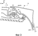
фиг. 3 - вид в разрезе по линии 3-3 с фиг. 5, показывающий конструкцию, корректирующую поворот, которая входит в состав конструкции задней двери, относящейся к первому варианту настоящего изобретения;FIG. 3 is a sectional view taken along line 3-3 of FIG. 5 showing a rotation correcting structure that is part of a rear door structure related to a first embodiment of the present invention;
фиг. 4 - вид в разрезе по линии 4-4 с фиг. 5, показывающий конструкцию для коррекции поворота, которая входит в состав конструкции задней двери, относящейся к первому варианту настоящего изобретения;FIG. 4 is a sectional view taken along line 4-4 of FIG. 5, showing a rotation correction structure that is part of a rear door structure related to a first embodiment of the present invention;
фиг. 5 - вид сзади, схематически показывающий конструкцию для коррекции поворота, которая входит в состав конструкции задней двери, относящейся к первому варианту настоящего изобретения;FIG. 5 is a rear view schematically showing a rotation correction structure that is part of a rear door structure related to a first embodiment of the present invention;
фиг. 6 - боковой вид в разрезе, схематически показывающий конструкцию для коррекции наклона, которая входит в состав конструкции задней двери, относящейся к первому варианту настоящего изобретения;FIG. 6 is a cross-sectional side view schematically showing a tilt correction structure that is part of a rear door structure related to a first embodiment of the present invention;
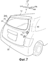
фиг. 7 - вид в перспективе, поясняющий силы реакции от демпфера в транспортном средстве, к которому применима конструкция задней двери, относящаяся к первому варианту настоящего изобретения;FIG. 7 is a perspective view illustrating reaction forces from a damper in a vehicle to which a tailgate structure related to a first embodiment of the present invention is applicable;
фиг. 8 - вид сзади, поясняющий поворотное смещение двери, наклонное смещение двери относительно кузова транспортного средства из-за силы реакции от демпфера и силы сопротивления, которая их подавляет, на транспортном средстве, к которому применима конструкция задней двери, относящаяся к первому варианту настоящего изобретения;FIG. 8 is a rear view explaining a rotational displacement of a door, an inclined displacement of a door relative to a vehicle body due to a reaction force from a damper and a resistance force that suppresses them, on a vehicle to which a rear door structure related to the first embodiment of the present invention is applicable;
фиг. 9 - графики, иллюстрирующие улучшение эффектов подгонки задней двери по сравнению со сравнительным примером благодаря конструкции задней двери, относящейся к первому варианту настоящего изобретения;FIG. 9 is a graph illustrating an improvement in tailgate fit effects compared to a comparative example due to the tailgate structure of the first embodiment of the present invention;
фиг. 10А - схематический вид, на котором воспроизведена конструкция перед поддержкой задней двери конструкцией для коррекции поворота, которая входит в состав конструкции задней двери, относящейся к первому варианту настоящего изобретения;FIG. 10A is a schematic view showing a structure in front of supporting a rear door with a rotation correction structure that is part of a rear door structure related to a first embodiment of the present invention;
фиг. 10В - схематический вид, на котором воспроизведена конструкция в состоянии поддержки задней двери конструкцией для коррекции поворота, которая входит в состав конструкции задней двери, относящейся к первому варианту настоящего изобретения;FIG. 10B is a schematic view showing a structure in a state of supporting a rear door with a rotation correction structure that is part of a structure of a rear door related to a first embodiment of the present invention;
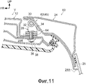
фиг. 11 - вид в разрезе по линии 11-11 с фиг. 12, показывающий конструкцию для коррекции поворота, которая входит в состав конструкции задней двери, относящейся ко второму варианту настоящего изобретения;FIG. 11 is a sectional view taken along line 11-11 of FIG. 12, showing a rotation correction structure that is part of a rear door structure related to a second embodiment of the present invention;
фиг. 12 - вид сзади, схематически показывающий конструкцию для коррекции поворота, которая входит в состав конструкции задней двери, относящейся ко второму варианту настоящего изобретения;FIG. 12 is a rear view schematically showing a rotation correction structure that is part of a rear door structure related to a second embodiment of the present invention;
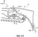
фиг. 13 - вид в разрезе по линии 13-13 с фиг. 14, показывающий конструкцию для коррекции поворота, которая входит в состав конструкции задней двери, относящейся к третьему варианту настоящего изобретения;FIG. 13 is a sectional view taken along line 13-13 of FIG. 14 showing a rotation correction structure that is part of a rear door structure related to a third embodiment of the present invention;
фиг. 14 - вид сзади, схематически показывающий конструкцию, для коррекции поворота, которая входит в состав конструкции задней двери, относящейся к третьему варианту настоящего изобретения;FIG. 14 is a rear view schematically showing a structure for pivoting correction, which is part of a rear door structure related to a third embodiment of the present invention;
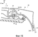
фиг. 15 - вид в разрезе по линии 15-15 с фиг. 18, показывающий конструкцию для коррекции поворота, которая входит в состав конструкции задней двери, относящейся к четвертому варианту настоящего изобретения;FIG. 15 is a sectional view taken along line 15-15 of FIG. 18 showing a rotation correction structure that is part of a rear door structure related to a fourth embodiment of the present invention;
фиг. 16 - вид сзади, схематически показывающий конструкцию для коррекции поворота, которая входит в состав конструкции задней двери, относящейся к четвертому варианту настоящего изобретения; иFIG. 16 is a rear view schematically showing a rotation correction structure that is part of a rear door structure related to a fourth embodiment of the present invention; and
фиг. 17 - боковой вид в разрезе, схематически показывающий конструкцию для коррекции наклона, которая входит в состав конструкции задней двери, относящейся к пятому варианту настоящего изобретения.FIG. 17 is a cross-sectional side view schematically showing a tilt correction structure that is part of a rear door structure related to a fifth embodiment of the present invention.
Наилучшие формы осуществления изобретенияBest Modes for Carrying Out the Invention
Далее со ссылкой на фи. 1-10 описывается конструкция 10 задней двери, к которой применима верхнеподвесная конструкция двери, относящаяся к первому варианту настоящего изобретения. Заметим, что стрелка FR, показанная на чертежах, указывает прямое направление в продольном направлении транспортного средства, стрелка UP указывает направление вверх в вертикальном направлении транспортного средства, стрелка RH указывает правую сторону, если смотреть в прямом направлении, то есть одну сторону в поперечном направлении транспортного средства, а стрелка LH соответственно указывает левую сторону, то есть направление, противоположное стрелке RH. Кроме того, в последующем пояснении при использовании продольного и вертикального направлений и направлений влево/вправо указаны продольное направление (продольное направление транспортного средства), вертикальное направление и направление влево/вправо транспортного средства V, если специально не упомянуто иное.Further with reference to phi. 1-10, a
На виде сзади на фиг. 1 показана схематическая конструкция транспортного средства V, к которому применима конструкция 10 задней двери. Как показано на этом чертеже, в кузове 12 транспортного средства V сформирована задняя открывающаяся часть 14, которая открывается назад. Задняя открывающаяся часть 14 является открывающейся частью для доступа в багажное отделение 16, которое представляет собой пространство в задней части пространства для пассажиров (сидения) транспортного средства V. Если более конкретно, то задняя открывающаяся часть 14 представляет собой открывающуюся часть, которая фактически имеет форму прямоугольника на виде сзади и окружена парой задних стоек 18 (левой и правой) (D стойки), задним основанием 20 крыши и задним бампером 22 (непоказанная нижняя задняя панель).In the rear view of FIG. 1 shows a schematic structure of a vehicle V to which a
Задняя открывающаяся часть 14 открывается и закрывается задней дверью 24, которая является примером двери в настоящем изобретении. В верхней части задней двери 24 сформировано заднее окно 24А, являющееся оконной частью, причем заднее окно 24А закрыто задним оконным стеклом 25. Задняя дверь 24 поддерживается относительно кузова 12 транспортного средства с возможностью поворота вокруг осей 30 шарниров, которые проходят в поперечном направлении транспортного средства через пару дверных шарниров 26, 28 (левый и правый), которые предусмотрены на заднем основании 20 крыши.The rear opening portion 14 is opened and closed by the
Если более конкретно, то, как показано на фиг. 3 и 4, в конструкции дверных шарниров 26, 28 предусмотрены основные части в виде кронштейнов 32 шарниров, на которых обеспечены соответствующие оси 30 шарниров и шарнирные лапы 34, которые поддерживаются с возможностью свободного поворота вокруг шарнирных осей 30 относительно шарнирных кронштейнов 32. Шарнирные кронштейны 32 смонтированы на кузове 12 транспортного средства путем их крепления к верхней поверхности заднего основания 20 крыши, образованного панелью основного кузова, с помощью болтов 36, проходящих через заднее основание 20 крыши в вертикальном направлении, и гаек 38. Шарнирные лапы 34 соединены с верхней концевой частью задней двери 24 непоказанными соединительными элементами (например, болты и гайки).More specifically, as shown in FIG. 3 and 4, the door hinges 26, 28 are provided with main parts in the form of
Благодаря такой конструкции задняя дверь 24 способна путем поворота вокруг шарнирных осей 30 занять полностью открытое положение, в котором задняя дверь 24 полностью открывает заднюю открывающуюся часть 14, как показано на фиг. 1, и занять полностью закрытое положение, в котором задняя дверь 24 полностью закрывает заднюю открывающуюся часть 14, как показано на фиг. 2. Заметим, что, как показано на фиг. 5, между задним основанием 20 крыши и каждым шарнирным кронштейном 32 находится прокладка 39, выполненная из синтетической резины или т.п.Due to such a structure, the
Кроме того, между кузовом 12 транспортного средства и задней дверью 24 предусмотрен демпфер 40, служащий в качестве механизма удержания двери. Демпфер 40 имеет цилиндр 42, служащий в качестве бокового элемента кузова транспортного средства, и стержень 4, служащий в качестве бокового элемента двери, который вставлен в цилиндр 42 с возможностью перемещения вперед и назад, причем демпфер 40 входит в состав конструкции для удержания двери, которая растягивается и сжимается, сопровождая перемещение стрежня 44 вперед и назад относительно цилиндра 42. Конструкция демпфера 40 обеспечивает создание силы сопротивления, сопровождающей укорачивание, с помощью не показанного здесь поршня, предусмотренного в цилиндре 42, и газа, которым заполнен цилиндр 42. В этом варианте конструкция демпфера 40 обеспечивает создание поддерживающей силы в направлении растяжения, когда устранено ограничение в направлении укороченного состояния. Поскольку конкретная конструкция демпфера 40 хорошо известна, ее описание здесь опущено.In addition, a
Как показано на фиг. 1, в демпфере 40 один конец 42А цилиндра 42 соединен с верхней частью кузова 12 транспортного средства с возможностью относительного углового перемещения, а один конец 44А стержня 44 соединен с промежуточной частью задней двери 24, проходящей в вертикальном направлении, с возможностью относительного углового перемещения. Конструкция демпфера 40 обеспечивает в растянутом состоянии удерживание задней двери 24 в полностью открытом состоянии, преодолевая (момент в направлении закрывания) собственный вес задней двери 24 благодаря вышеупомянутой силе сопротивления.As shown in FIG. 1, in the
С другой стороны, при приложении к задней двери 24 внешней силы, направленной вниз, и приложении нагрузки в направлении укорачивания, которая превышает вышеупомянутую силу сопротивления, демпфер 40, находясь в укороченном состоянии, позволяет задней двери 24 перемещаться в сторону полностью закрытого положения. В полностью закрытом положении, показанном на фиг. 2, демпфер 40 находится в укороченном состоянии. Кроме того, конструкция демпфера 40 такова, что при перемещении задней двери 40 из полностью закрытого положения в сторону полностью открытого положения создается вышеупомянутая поддерживающая сила при удлинении. Таким образом, демпфер 40 прикладывает нагрузку к задней двери 24 даже в полностью закрытом положении, как описывается ниже.On the other hand, by applying an external force directed downward to the
Кроме того, в конструкции 10 задней двери предусмотрен только один демпфер 40. В этом варианте единственный демпфер 40 расположен с правой стороны (внешняя сторона в поперечном направлении транспортного средства, которое является горизонтальным направлением) по отношению к задней открывающейся части 14. Если более конкретно, то один конец 42А цилиндра 42 соединен с задней стойкой 18 с правой стороны, а один конец 44А стержня 44 соединен с правосторонней частью по отношению к заднему окну 24А на задней двери 24.In addition, only one
Таким образом, в конструкции 10 задней двери нагрузка от демпфера 40, которая прикладывается к задней двери 24 в вышеописанном полностью закрытом положении, имеет левую/правую асимметрию. Если более конкретно, то в правой концевой части задней двери 24, как показано на фиг. 7, от демпфера 40 прикладывается нагрузка Fd, направленная вниз. Кроме того, как показано на этом чертеже, в полностью закрытом положении задней двери 24 демпфер 40 расположен с наклоном, так что нижний конец (один конец 44А стержня 44) располагается дальше по направлению к задней стороне транспортного средства, чем верхний конец (один конец 42А цилиндра 42). Таким образом, от демпфера 40 на правой концевой части задней двери 24 прикладывается нагрузка Fb, направленная назад.Thus, in the structure of the
Как показано на фиг. 8, из-за нагрузки Fd, конструкция задней двери 24 обеспечивает создание поворотного смещения (по стрелке А), так что происходит относительное смещение правой боковой части задней двери 24 вниз, а левой боковой части вверх.As shown in FIG. 8, due to the load Fd, the design of the
Здесь в конструкции 10 боковой двери предусмотрена конструкция 45 для поддерживания двери. Можно понять, что конструкция 45 для поддерживания двери корректирует положение задней двери 24 относительно кузова 12 транспортного средства в отличие от случая, в котором задняя дверь 24 создает вышеупомянутое поворотное смещение и смещение с наклоном относительно кузова 12 транспортного средства, когда указанная конструкция 45 для поддерживания двери не предусмотрена. Далее следует конкретное описание.Here, the
Как показано на фиг. 5, конструкция 45 для поддерживания двери включает в себя конструкцию 46 для коррекции поворота, которая различает высоту в вертикальном направлении монтажных поверхностей 20L, 20R левого и правого дверных шарниров 26, 28 на заднем основании 20 крыши в состоянии, когда задняя дверь 24 не поддерживается. В конструкции 46 для коррекции поворота монтажная поверхность 20R на правой стороне, где расположен демпфер 40, смещена в направлении верхней стороны относительно монтажной поверхности 20L на левой стороне, где демпфер 40 не предусмотрен. А именно, в конструкции 10 задней двери в состоянии, когда поддерживается задняя дверь 24, шарнирная ось 30 с правой стороны смещена в направлении верхней стороны дальше, чем шарнирная ось 30 с левой стороны.As shown in FIG. 5, the
Как можно понять из сравнения фиг. 3 и 4, монтажная поверхность 20L представляет собой верхнюю поверхность выступающей части 20А листового металла, который образует заднее основание 20 крыши, причем эта верхняя поверхность смещена в направлении верхней стороны по отношению к монтажной поверхности 20R, которая является основной поверхностью листового металла, образующего заднее основание 20 крыши. Назначение этой конструкции 46 для коррекции поворота описано ниже вместе с описанием работы согласно первому варианту.As can be understood from the comparison of FIG. 3 and 4, the mounting
Кроме того, конструкция 45 для поддерживания двери включает в себя конструкцию 48 для коррекции наклона. В конструкции 48 для коррекции наклона предусмотрен стопор 50 для регулировки подгонки на нижней левой части между задней дверью, которая находится в полностью закрытом положении, и кузовом 12 транспортного средства. А именно, в конструкции 48 для коррекции наклона стопор 50, который служит в качестве регулировочного элемента, расположен на противоположной стороне в вертикальном направлении и слева/справа (в горизонтальном направлении) по отношению к стороне, где установлен демпфер 40 (в месте, которое фактически образует диагональ по отношению к положению, в котором установлен демпфер 40).In addition, the
Стопор 50 в этом варианте обеспечен таким образом, что он выступает назад, как показано на фиг. 6, в положении, которое перекрывает нижнюю левую часть задней двери 24 в ее полностью закрытом положении на виде сзади у нижней части задней стойки 18 на левой стороне (окрестность границы с нижней задней панелью), как показано на фиг. 1. Если более конкретно, то стопор 50 сформирован в форме цилиндра из, например, резины или т.п., причем его передняя концевая сторона удерживается у вышеупомянутой задней стойки 18 на левой стороне, а задняя концевая сторона является свободным концом.The
Конструкция стопора 50 такова, что в состоянии упругого сжатия в продольном направлении благодаря его расположению между задней дверью 24 в полностью закрытом положении и задней стойкой 18 обеспечивается регулировка смещения вперед задней двери 24 относительно кузова 12 транспортного средства. На фиг. 6 пунктирной линией показан стопор 50 в свободном состоянии. А именно, в конструкции 48 для коррекции наклона стопор 50 выполнен с возможностью перекрытия, в результате чего, пространство, занимаемое стопором 50 в свободном состоянии, и пространство, занимаемое задней дверью 24 в полностью закрытом положении, перекрываются.The design of the
Соответственно, стопор 50, входящий в состав конструкции 48 для коррекции наклона (конструкция 45 для поддерживания двери), образован в виде элемента, отделенного от непоказанного стопора для предотвращения сильного закрывания, то есть для регулирования задней двери 24, проходящей в полностью закрытое положение и достигающей кузова 12 транспортного средства. Кроме того, стопор 50 выполнен из более мягкого материала по сравнению со стопором для предотвращения сильного закрывания.Accordingly, the
Кроме того, в данном варианте величина выступа стопора 50 по отношению к кузову 12 транспортного средства (величина перекрытия с задней дверью 24) может регулироваться; а если более конкретно, то с передней концевой стороны стопора 50 формируется охватываемая винтовая часть 50А, и эта охватываемая винтовая часть 50А ввинчивается в резьбовое отверстие 52, сформированное в нижней стойке 18. Соответственно, получается конструкция, в которой благодаря повороту стопора 50 вокруг своей оси можно регулировать величину выступа стопора 50 по отношению к кузову 12 транспортного средства.In addition, in this embodiment, the protrusion value of the
Кроме того, в конструкции 45 для поддерживания двери в данном варианте (фланец с отверстием, сформированный в продольном направлении) периферийная краевая часть заднего окна 24А в задней двери 24 оказывается усиленной. Усиленные зоны 24RF в этом варианте показаны на фиг. 2 пунктирными линиями. В качестве такой усиливающей конструкции используется конструкция, которая увеличивает силу сцепления между боковой дверью 24 и стеклом 25 заднего окна, защищая заднее окно 24А. В этом варианте периферийная краевая часть заднего окна 24А в задней двери 24 усиливается посредством использования уретанового клея (коэффициент упругости после отверждения 0,8 МПа), имеющего большую силу сцепления, чем обычный полиуретановый клей (коэффициент упругости после отверждения 0,1 МПа). Заметим, что усиленный полиуретановый клей можно использовать по всей периферии заднего окна 24А, либо его можно использовать только для краевых частей, проходящих в вертикальном направлении заднего окна 24А в задней двери 24.In addition, in the
Далее описывается принцип действия настоящего варианта осуществления изобретения.The following describes the principle of operation of the present embodiment.
В вышеописанной конструкции 10 задней двери, когда задняя открывающаяся часть 14 открыта, не допускается состояние защелкивания задней двери с помощью непоказанного язычка и механизма защелки. Таким образом, задняя дверь 24, больше не ограниченная язычком и механизмом защелки, перемещается в полностью открытое положение поддерживающей силой, которая сопровождает растяжение демпфера 40, а также легким усилием, прикладываемым пользователем. Собственный вес задней двери 24 (момент в горизонтальном направлении) в полностью открытом положении поддерживается силой сопротивления демпфера 40, и задняя дверь 24 удерживается в этом полностью открытом положении. С другой стороны, при закрывании задней открывающейся части 14 нижняя часть задней двери 24 (задняя часть в полностью открытом положении) выталкивается вниз, преодолевая силу сопротивления демпфера 40. Затем задняя дверь 24 поворачивается вниз вокруг шарнирных осей 30, в то время как демпфер 40 укорачивается, и, когда задняя дверь 24 достигает полностью закрытого положения, она защелкивается язычком и механизмом защелки. В этом состоянии стопор 50 зажимается между задней дверью 24 и задней стойкой 18.In the above-described design of the
Впрочем, в конструкции 10 задней двери, где единственный демпфер 40 соединяет кузов 12 транспортного средства и заднюю дверь 24 на одной концевой стороне в поперечном направлении транспортного средства, как было описано выше, поворотное смещение в направлении стрелки А из-за нагрузки Fd и наклонное смещение в направлении стрелки В из-за нагрузки Fb возрастают, как было описано выше. Таким образом, в сравнительном примере, где отсутствует конструкция 45 для поддерживания двери (конструкция 45 для поддерживания двери и конструкция 48 для коррекции наклона), задняя дверь 24 поворачивается в направлении стрелки А и устанавливается в кузове транспортного средства в положении с наклоном в направлении стрелки В, по сравнению с правильной подгонкой (положение установки) задней двери 24 по отношению к кузову 12 транспортного средства.However, in the
Если более конкретно, то, как показано на фиг. 9, из сравнительного примера, который показан кривыми из черных точек, можно понять, что верхний конец и нижний конец задней двери 24 сильнее перемещаются вниз в направлении правой стороны (сторона, на которой установлен демпфер 40) из-за поворотного смещения в направлении стрелки А. Очевидно, что в сравнительном примере на верхнем конце, нижнем конце задней двери 24 позиционные различия в вертикальном направлении между соответствующими правыми концами и левыми концами будут велики, и также будут велики различия по отношению к эталонному положению (смещение 0) на правых концевых сторонах. Кроме того, позиционное различие по вертикали между левой и правой стороной, которое больше на нижнем конце, чем на верхнем конце задней двери 24, вызывает деформацию вниз самой задней двери 24.More specifically, as shown in FIG. 9, from the comparative example, which is shown by the curves from black dots, it can be understood that the upper end and lower end of the
Кроме того, можно понять, что в этом сравнительном примере правый конец задней двери 24 сильно смещается назад от эталонного положения (смещение 0) из-за наклонного смещения в направлении стрелки В. Кроме того, очевидно, что из-за наклонного смещения в направлении стрелки В правый конец и левый конец задней двери 24 сильно смещаются к левой стороне в поперечном направлении транспортного средства.Furthermore, it can be understood that in this comparative example, the right end of the
В противоположность этому, в конструкции 10 задней двери, имеющей конструкцию 46 для коррекции поворота, как показано на фиг. 9, смещение в вертикальном направлении верхнего конца, нижнего конца задней двери 24 из-за поворотного смещения в направлении стрелки А не допускается в отличие от вышеописанного сравнительного примера. А именно, в конструкции 46 для коррекции поворота в состоянии перед поддержкой задней двери 24 монтажная поверхность 20R с правой стороны (сторона, где установлен демпфер 40) расположена на верхней стороне по отношению к монтажной поверхности 20L с левой стороны. Таким образом, правая сторона задней двери 24 смещается вниз сильнее, чем левая сторона на величину, соответствующую, по меньшей мере, части (ΔH) позиционного различия в вертикальном направлении между монтажной поверхностью 20L и монтажной поверхностью 20R, сопровождая поворот в направлении стрелки А. Соответственно, сокращается различие левого/правого смещения у верхнего конца, нижнего конца задней двери 24 по сравнению с вышеописанным сравнительным примером на величину, соответствующую, по меньшей мере, части различия ΔH левого/правого смещения.In contrast, in the
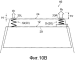
Кроме того, поскольку задняя дверь 24 сильно деформирует сторону 20R монтажной поверхности заднего основания 20 крыши на величину, соответствующую вышеупомянутому ΔH, по отношению к стороне 20L монтажной поверхности, поддерживающая сила реакции от кузова транспортного средства с правой стороны будет больше, чем с левой стороны. Конкретно, как схематически показано на фиг. 10А, это можно смоделировать в виде конструкции, где монтажная поверхность 20L (дверной шарнир 26), монтажная поверхность 20R (дверной шарнир 28) заднего основания 20 крыши поддерживаются соответственно пружинами Sl, Sr, имеющими коэффициент K жесткости и собственную длину L, а монтажная поверхность 20R смещена вверх относительно монтажной поверхности 20L. Как показано на фиг. 10В, при условии, что величина деформации пружины Sl с левой стороны в состоянии поддержки задней двери 24 равна Hl, а величина деформации пружины Sr с правой стороны составляет Hr(=Hl+ΔH), поддерживающая сила Rl реакции на стороне Sl пружины составит Rl=K×Hl, а поддерживающая сила Rr реакции со стороны пружины Sr составит Rr=K×Hr.In addition, since the
Благодаря этому в конструкции 10 задней двери поддерживающая сила Rr реакции от шарнира 28 с правой стороны оказывается больше на величину, соответствующую ΔR=K×ΔH, чем поддерживающая сила Rl реакции от дверного шарнира 26 с левой стороны, в связи с чем предотвращается самоповорот задней двери 24 в направлении стрелки А. А именно, на основе указанного различия сил реакции, как показано на фиг. 8, момент Ma в направлении, противоположном стрелке А, возрастает, в связи с чем исключается поворот задней двери 24 в направлении стрелки А благодаря указанному моменту Ma.Due to this, in the design of the
По этим причинам в вышеописанной конструкции 10 задней двери не допускается перемещение в вертикальном направлении верхнего конца, нижнего конца задней двери 24 благодаря поворотному смещению в направлении стрелки А.For these reasons, in the above-described construction of the
Кроме того, в конструкции 10 задней двери конструкция 45 для поддерживания двери имеет усиленную конструкцию открывающегося фланца периферийного края заднего окна 24А в задней двери 24. Таким образом, на задней двери 24 предотвращается деформирование правой части вниз из-за направленной вниз нагрузки Fd от демпфера 40. Благодаря этому, как можно понять из сравнения величин деформации в вертикальном направлении верхней концевой стороны и нижней концевой стороны, показанных на фиг. 9, не наблюдается значительное различие в величинах деформации слева и справа на верхнем конце и нижнем конце задней двери 24.In addition, in the
Кроме того, в конструкции 10 задней двери, которая имеет конструкцию 48 для коррекции наклона, по сравнению с вышеописанным сравнительным примером, показанным на фиг. 9, исключается смещение в продольном направлении левого конца, правого конца задней двери 24 из-за наклонного смещения. А именно, в конструкции 48 для коррекции наклона предусмотрен стопор 50 на стороне, противоположной стороне, где установлен демпфер 40, который толкает заднюю дверь 24 назад благодаря нагрузке Fb, и поскольку этот стопор 50 находится в сжатом деформированном состоянии между задней дверью 24 в полностью закрытом положении и кузовом 12 транспортного средства, момент Mb (смотри фиг.8) в противоположном направлении (направление по стрелке В) возрастает на основе направленной назад силы восстановления стопора 50. Из-за этого момента Mb не допускается наклон задней двери 24 в направлении стрелки В.Furthermore, in the
Благодаря этому, как показано на фиг. 9, в конструкции 10 задней двери не допускается смещение правого конца задней двери 24 назад, а также уменьшается различие в смещении двери вверх/вниз, по сравнению с вышеописанным сравнительным примером. Кроме того, также исключается смещение задней двери 24 в поперечном направлении транспортного средства по сравнению с вышеописанным сравнительным примером.Due to this, as shown in FIG. 9, in the structure of the
Благодаря вышеуказанному в конструкции 10 задней двери, относящейся к первому варианту, при использовании варианта конструкции с единственным демпфером 40 задняя дверь 24 может быть правильно (в рамках допуска) установлена в кузове 12 транспортного средства (с обеспечением качественной подгонки). В транспортном средстве V, в котором применяется указанная конструкция 10 задней двери, задняя дверь 24 может быть установлена в кузове 12 транспортного средства путем подгонки, такой же, как в случае транспортного средства, имеющего пару (левый, правый) демпферов 40. Таким образом, в транспортном средстве V, в котором применена конструкция 10 задней двери, по сравнению с транспортным средством, имеющим пару (левый, правый) демпферов 40, можно добиться аналогичной подгонки, если вместо одного из демпферов 40 предусмотреть стопор 50, и тогда можно уменьшить затраты при обеспечении аналогичного качества подгонки задней двери 24.Due to the aforementioned design of the
Кроме того, в конструкции 10 задней двери монтажная поверхность 20R выполнена со смещением вверх относительно монтажной поверхности 20L, и обеспечена конструкция, в которой обеспечивается различие в их положении в вертикальном направлении.In addition, in the
Таким образом, левый и правый дверные шарниры 26, 28 могут быть выполнены как общие детали, и, кроме того, левая и правая прокладки 39 могут использоваться как общие, что дополнительно уменьшает затраты.Thus, the left and right door hinges 26, 28 can be made as common parts, and in addition, the left and
Кроме того, в конструкции задней двери стопор 50, который сформирован из мягкого материала с возможностью перекрывания, всегда контактирует с задней дверью 24, которая находится в полностью зарытом состоянии, в связи с чем исключается дребезжание нижней концевой части задней двери 24 относительно кузова 12 транспортного средства, что соответственно исключает возникновение вибрации и шума, вызванных дребезжанием задней двери 24. А именно, при обеспечении качественной подгонки задней двери 24 относительно кузова 12 транспортного средства можно обеспечить подавление вибраций и шумов, что также вносит вклад в повышение привлекательности транспортного средства V как товара широкого потребления.In addition, in the design of the rear door, the
Кроме того, путем регулировки положения свинченных вместе части 50А с наружной резьбой с винтовым отверстием 52 величина выступа стопора 50 над кузовом транспортного средства может регулироваться в соответствии, например, с разбросом погрешностей линейных размеров кузова 12 транспортного средства и задней двери 24 или т.п. Кроме того, стопор 50 также может быть использован в разных типах транспортных средств.In addition, by adjusting the position of the male-threaded
Заметим, что в первом варианте показан пример, где благодаря установке монтажной поверхности 20R у выступающей части 20А заднего основания 20 крыши монтажная поверхность 20R смещена вверх по отношению к монтажной поверхности 2L, но настоящее изобретение к этому не сводится, и, например, возможна конструкция, где монтажная поверхность 20R смещена вверх относительно монтажной поверхности 20L, например, путем установки монтажной поверхности 20L в углублении, сформированном в заднем основании 20 крыши.Note that in the first embodiment, an example is shown where, due to the installation of the mounting
Другие вариантыOther options
Далее описываются другие варианты настоящего изобретения. Следует отметить, что детали и части, по сути аналогичные конструкциям вышеописанного первого варианта или которые были описаны ранее, обозначены такими же ссылочными позициями, как конструкции в вышеописанном первом варианте или описанные ранее, в связи с чем их описание опущено.Other embodiments of the present invention are described below. It should be noted that parts and parts that are essentially similar to the structures of the above-described first embodiment or which were described earlier are indicated by the same reference numbers as the structures in the above-described first embodiment or described previously, and therefore their description is omitted.
Второй вариант осуществления изобретенияSecond Embodiment
На фиг. 11 на боковом виде в разрезе, соответствующем фиг. 3, показана конструкция 60 задней двери, в которой используется верхнеподвесная конструкция, относящаяся ко второму варианту настоящего изобретения. Как показано на этом чертеже, конструкция 60 задней двери такова, что ее конструкция 45 для поддерживания двери вместо конструкции 46 для коррекции поворота имеет конструкцию 62 для коррекции поворота. Конструкция 62 для коррекции поворота такова, что монтажная поверхность 20R выполнена как общая поверхность заднего основания 20 крыши так же, как монтажная поверхность 20L, а вместо прокладки 39 предусмотрена прокладка 64.In FIG. 11 in a side sectional view corresponding to FIG. 3, a
Прокладка 64 толще, чем прокладка 39, и из-за этого, как показано на фиг. 12, возникает позиционное различие в вертикальном направлении между (соответствующими осями 30 шарниров) дверным шарниром 26 и дверным шарниром 28 в состоянии, когда задняя дверь 24 не поддерживается. Кроме того, прокладка 64 имеет жесткость (коэффициент жесткости пружины), равную или большую, чем прокладка 39, и при выполнении установки задней двери 24 деформируется, сжимаясь более сильно, чем прокладка 39. Другие конструктивные особенности в конструкции 60 задней двери, включая непоказанные части, по существу аналогичны соответствующим конструктивным особенностям конструкции 10 задней двери, относящейся к первому варианту.The
Соответственно, конструкция 60 задней двери, относящаяся ко второму варианту, имеет принцип действия и эффекты, в основном аналогичные конструкции 10 задней двери. Заметим, что в конструкцию 60 задней двери также включены конструкции, где жесткость прокладки 60 установлена низкой или т.п., но эффекты из-за различия ΔH в величине деформации в вертикальном направлении между прокладкой 64 и прокладкой 39, создающей момент Ma, не проявляются, либо указанные эффекты малы.Accordingly, the
Третий вариант осуществления изобретенияThird Embodiment
На фиг. 13 на боковом виде в разрезе, соответствующем фиг. 3, показана конструкция 70 задней двери, в которой используется верхнеподвесная конструкция, относящаяся к третьему варианту настоящего изобретения. Как показано на этом чертеже, конструкция 70 задней двери такова, что ее конструкция 45 для поддерживания двери вместо конструкции 46 для коррекции поворота имеет конструкцию 72 для коррекции поворота. Конструкция 72 для коррекции поворота такова, что монтажная поверхность 20R выполнена как общая поверхность заднего основания 20 крыши так же, как монтажная поверхность 20L, и вместо кронштейна 32 шарнира дверной шарнир 28 имеет кронштейн 74 шарнира, высота которого больше в вертикальном направлении.In FIG. 13 in a side sectional view corresponding to FIG. 3, a
А именно, как показано на фиг. 14, кронштейн 74 шарнира, который входит в состав дверного шарнира 28, таков, что высота от общей поверхности заднего основания 20 крыши, то есть монтажных поверхностей 20L, 20R, до шарнирной оси 30 велика по сравнению с кронштейном 32 дверного шарнира 26. Благодаря этому в конструкции 70 задней двери кронштейн 74 шарнира создает различие в вертикальном направлении между (соответствующими шарнирными осями 30) дверным шарниром 26 и дверным шарниром 28 в состоянии, когда задняя дверь 24 не поддерживается. Другие конструктивные особенности в конструкции 70 задней двери, включая непоказанные части, по существу аналогичны соответствующим конструктивным особенностям конструкции 10 задней двери, относящейся к первому варианту.Namely, as shown in FIG. 14, the
Соответственно, конструкция 70 задней двери, относящаяся ко второму варианту, имеет принцип действия и эффекты, в основном аналогичные конструкции 10 задней двери.Accordingly, the
Четвертый вариант осуществления изобретенияFourth Embodiment
На фиг. 15 на боковом виде в разрезе, соответствующем фиг. 3, показана конструкция 80 задней двери, в которой используется верхнеподвесная конструкция, относящаяся к четвертому варианту настоящего изобретения. Как показано на этом чертеже, конструкция 80 задней двери такова, что ее конструкция 45 для поддерживания двери вместо конструкции 46 для коррекции поворота имеет конструкцию 82 для коррекции поворота. Конструкция 82 для коррекции поворота такова, что монтажная поверхность 20R выполнена как общая поверхность заднего основания 20 крыши так же, как монтажная поверхность 20L, и вместо прокладки 39 имеется прокладка 84.In FIG. 15 in a sectional side view corresponding to FIG. 3, a
Прокладка 84 выполнена, например, из металлического материала или т.п. и имеет более высокую жесткость, чем прокладка 39, выполненная из синтетической смолы или т.п. В этом варианте толщина прокладки 84 эквивалентна толщине прокладки 39. Другие конструктивные особенности в конструкции 60 задней двери, включая непоказанные части, по существу аналогичны соответствующим конструктивным особенностям конструкции 10 задней двери, относящейся к первому варианту.The
Соответственно, конструкция 80 задней двери, относящаяся к четвертому варианту, имеет принцип действия и эффекты, в основном аналогичные конструкции 10 задней двери. В дополнение к этому в конструкции 80 задней двери различие в жесткости (легкость деформации) левой и правой прокладок 39, 82 соответствует различию в положении в вертикальном направлении между монтажной поверхностью 20L и монтажной поверхностью 20R в конструкции 10 задней двери. А именно, в конструкции 80 задней двери при выполнении поворотного смещения задней двери 24 в направлении стрелки А заднее основание 20 крыши деформируется более сильно с правой стороны (сторона, с которой установлен демпфер 40), чем с левой стороны на величину, соответствующую различию в степени деформации левой и правой прокладок 39, 82, в связи с чем поддерживающая сила реакции с правой стороны оказывается большой, и исключается вышеупомянутое поворотное смещение задней двери 24. С другой стороны, поскольку прокладка 39 деформируется, сжимаясь сильнее, чем прокладка 84, исключается различие в смещении в вертикальном направлении задней двери 24 влево и вправо.Accordingly, the
Пятый вариант осуществления изобретенияFifth Embodiment
На фиг. 17 на боковом виде в разрезе, соответствующем фиг. 3, показана конструкция 90 задней двери, в которой используется верхнеподвесная конструкция, относящаяся к пятому варианту настоящего изобретения. Как показано на этом чертеже, конструкция 90 задней двери такова, что ее конструкция 45 для поддерживания двери вместо конструкции 48 для коррекции наклона имеет конструкцию 92 для коррекции наклона. Конструкция 92 для коррекции наклона такова, что стопор 50 вместо задней стойки 18 (кузов 12 транспортного средства) смонтирован на задней двери 24.In FIG. 17 in a sectional side view corresponding to FIG. 3, a rear door structure 90 is shown in which a top suspension structure relating to a fifth embodiment of the present invention is used. As shown in this drawing, the structure of the rear door 90 is such that its
В состав конструкции 92 для коррекции наклона входит стопор 50, который ввинчен в винтовое отверстие 52, сформированное в задней двери 24, причем стопор 50 смонтирован так, что имеется возможность регулировки величины его выступа в направлении кузова 12 транспортного средства. Хотя это не показано, позиция стопора 50 в конструкции 92 коррекции наклона, как видно на виде сзади, совпадает с позицией стопора 50 в конструкции 10 (60, 70, 80) задней двери, как видно на соответствующем виде сзади. Другие конструктивные особенности в конструкции 90 задней двери, включая непоказанные части, по существу аналогичны соответствующим конструктивным особенностям конструкции 10 задней двери, относящейся к первому варианту.The
Соответственно, конструкция 90 задней двери, относящаяся к пятому варианту, имеет принцип действия и эффекты, в основном аналогичные конструкции 10 задней двери. Заметим, что в вышеописанных соответствующих вариантах приведены примеры, в которых конструкция 45 для поддерживания двери имеет как конструкцию 46, 62, 72, 82 для коррекции поворота, так и конструкцию 48, 92 для коррекции наклона, но настоящее изобретение этим не ограничено, и возможны конструкции, имеющие, например, либо конструкцию 46, 62, 72, 82 для коррекции поворота, либо конструкцию 48, 92 для коррекции наклона.Accordingly, the rear door structure 90 related to the fifth embodiment has an operating principle and effects substantially similar to the
Кроме того, в вышеописанных соответствующих вариантах приведены примеры, в которых периферийная краевая часть заднего окна 24А на задней двери 24 является усиленной, но настоящее изобретение этим не ограничено, и возможны конструкции, в которых, например, периферийная краевая часть заднего окна 24А на задней двери 24 не усилена. Кроме того, вместо усиления конструкции с помощью адгезива возможна конструкция, в которой периферийная краевая часть заднего окна 24А на задней двери 24 усилена путем увеличения толщины открытого фланца периферийного края заднего окна 24 или присоединения усиливающего элемента.In addition, in the above-described respective embodiments, examples are given in which the peripheral edge portion of the
Кроме того, в вышеописанных вариантах приведены примеры, в которых демпфер 40 расположен с правой стороны кузова 12 транспортного средства, задней двери 24, но настоящее изобретение этим не ограничено, и возможна конструкция, в которой, например, демпфер 40 расположен с левой стороны кузова 12 транспортного средства, задней двери 24.In addition, in the above embodiments, examples are given in which the
Кроме того, в вышеописанных вариантах приведены примеры, в которых в качестве механизма удержания двери используется демпфер 40, являющийся газовым демпфером, но настоящее изобретение этим не ограничивается, и в качестве механизма удержания двери может быть использован демпфер, который вместо или вдобавок к газу заполнен жидкостью (маслом), или, например, в качестве механизма удержания двери может быть использована комбинация демпфера и рычажного механизма.In addition, in the above embodiments, examples are given in which the
Наряду с этим, в вышеописанных вариантах приведены примеры, в которых на стопоре 50 сформирована часть 50А с наружной резьбой, и имеется возможность регулировки величины выступа стопора 50 в направлении задней двери 24 (или кузова 12 транспортного средства), но настоящее изобретение этим не ограничивается, и возможны, например, конструкции, где стопор 50 закреплен на кузове 12 транспортного средства или задней двери 24.In addition, in the above embodiments, examples are given in which an
Кроме того, в вышеописанных вариантах приведены примеры, в которых в конструкции 10, 60, 70, 80, 90 используется верхнеподвесная конструкция двери, относящаяся к настоящему изобретению, но настоящее изобретение можно применить, например, к конструкции боковой двери типа «крыло чайки», которая поворачивается вокруг оси шарнира, проходящей в продольном направлении, и открывает и закрывает открывающуюся часть, предназначенную для входа/выхода пассажиров.In addition, in the above embodiments, examples are given in which a top-hanging door structure related to the present invention is used in the
Наряду с этим, в вышеописанных вариантах приведены примеры, в которых дверной шарнир 26, дверной шарнир 28 крепятся к заднему основанию 20 крыши болтами 36, проходящими вертикально через монтажные поверхности 20L, 20R, которые обращены к верхней стороне, но настоящее изобретение этим не ограничивается, и возможны конструкции, в которых, например, указанные дверной шарнир 26, дверной шарнир 28 крепятся к заднему основанию 20 крыши болтами 36, проходящими горизонтально через монтажные поверхности 20L, 20R, которые обращены назад.In addition, in the above embodiments, examples are given in which the
Claims (18)
пару шарниров, обеспеченных на кузове транспортного средства, так что они отстоят друг от друга в горизонтальном направлении и находятся на верхней стороне в вертикальном направлении транспортного средства по отношению к открывающейся части, сформированной в кузове транспортного средства;
дверь, которая поддерживается в кузове транспортного средства парой шарниров и которая открывает и закрывает открывающуюся часть путем поворота относительно осей шарниров, являющихся осями вращения;
механизм удержания двери, обеспеченный между дверью и кузовом транспортного средства с одной концевой стороны двери в горизонтальном направлении, который создает силу сопротивления, преодолевающую собственный вес двери, и поддерживает положение, в котором дверь полностью открывает открывающуюся часть, и который из-за нагрузки, превышающей силу сопротивления, позволяет двери перемещаться в направлении закрывания открывающейся части; и
конструкцию для поддерживания двери, которая выполнена так, что в состоянии, когда дверь не поддерживается, ось одного шарнира, расположенного на стороне, где установлен механизм удержания двери между парой шарниров, расположена дальше в направлении верхней стороны в вертикальном направлении транспортного средства, чем ось другого шарнира.1. A top-hung door structure comprising:
a pair of hinges provided on the vehicle body, so that they are spaced apart from each other in the horizontal direction and are on the upper side in the vertical direction of the vehicle with respect to an opening portion formed in the vehicle body;
a door that is supported in the vehicle body by a pair of hinges and which opens and closes the opening part by rotation about the hinge axes, which are rotation axes;
a door holding mechanism provided between the door and the vehicle body at one end of the door in the horizontal direction, which creates a resistance force that overcomes the own weight of the door and maintains a position in which the door completely opens the opening part, and which due to a load exceeding resistance force, allows the door to move in the direction of closing the opening part; and
a structure for supporting the door, which is designed so that in a state where the door is not supported, the axis of one hinge located on the side where the door holding mechanism is installed between the pair of hinges is located further in the direction of the upper side in the vertical direction of the vehicle than the axis of the other hinge.
соответствующие монтажные поверхности являются поверхностями, которые обращены к верхней стороне в вертикальном направлении транспортного средства, и
пара шарниров закреплена на кузове транспортного средства болтами, которые проходят в вертикальном направлении транспортного средства сквозь панель кузова транспортного средства, имеющую монтажные поверхности.3. The upper suspension door structure according to claim 2, in which
respective mounting surfaces are surfaces that face the upper side in the vertical direction of the vehicle, and
a pair of hinges is fixed on the vehicle body with bolts that extend in the vertical direction of the vehicle through the vehicle body panel having mounting surfaces.
механизм удержания двери создает поддерживающую силу при растяжении, когда дверь открывает открывающуюся часть, и создает силу сопротивления при укорачивании, когда дверь закрывает открывающуюся часть.7. The upper suspension door structure according to claim 1 or 2, in which a vehicle body side element is provided in the door holding mechanism structure, connected to a part located on one end side in a horizontal direction relative to an opening part on the upper part of the vehicle body, and a side a door element connected to the same side as the connected side of the side member of the vehicle body with respect to the opening part at the door, the side body member tr nsportnogo means and side door element is connected with the possibility of expansion and contraction due to relative displacement in mutually longitudinally, and
the door holding mechanism creates a tensile support force when the door opens the opening part, and creates a shortening resistance force when the door closes the opening part.
пару шарниров, обеспеченных на кузове транспортного средства так, что они отстоят друг от друга в горизонтальном направлении и находятся на верхней стороне в вертикальном направлении транспортного средства по отношению к открывающейся части, сформированной в кузове транспортного средства;
дверь, которая поддерживается в кузове транспортного средства парой шарниров и которая открывает и закрывает открывающуюся часть путем поворота относительно осей шарниров, являющихся осями вращения;
механизм удержания двери, обеспеченный между дверью и кузовом транспортного средства с одной концевой стороны двери в горизонтальном направлении, который создает силу сопротивления, преодолевающую собственный вес двери, и поддерживает положение, в котором дверь полностью открывает открывающуюся часть, и который из-за нагрузки, превышающей силу сопротивления, позволяет двери перемещаться в направлении закрывания открывающейся части; и
конструкцию для поддерживания двери, которая выполнена так, что поддерживающая сила реакции, в вертикальном направлении транспортного средства, монтажной части одного шарнира, расположенного на стороне, где установлен механизм удержания двери между парой шарниров, превышает поддерживающую силу реакции, в вертикальном направлении транспортного средства, монтажной части другого шарнира.8. A top-hung door structure comprising:
a pair of hinges provided on the vehicle body so that they are spaced apart from each other in the horizontal direction and are on the upper side in the vertical direction of the vehicle with respect to an opening portion formed in the vehicle body;
a door that is supported in the vehicle body by a pair of hinges and which opens and closes the opening part by rotation about the hinge axes, which are rotation axes;
a door holding mechanism provided between the door and the vehicle body at one end of the door in the horizontal direction, which creates a resistance force that overcomes the own weight of the door and maintains a position in which the door completely opens the opening part, and which due to a load exceeding resistance force, allows the door to move in the direction of closing the opening part; and
a structure for supporting the door, which is designed so that the supporting reaction force in the vertical direction of the vehicle, the mounting part of one hinge located on the side where the door holding mechanism is installed between the pair of hinges, exceeds the supporting reaction force in the vertical direction of the vehicle, mounting parts of another hinge.
соответствующие монтажные поверхности являются поверхностями, которые обращены к верхней стороне в вертикальном направлении транспортного средства, и
пара шарниров закреплена на кузове транспортного средства болтами, которые проходят в вертикальном направлении транспортного средства сквозь панель кузова транспортного средства, имеющую монтажные поверхности.10. The upper suspension door structure according to claim 9, in which
respective mounting surfaces are surfaces that face the upper side in the vertical direction of the vehicle, and
a pair of hinges is fixed on the vehicle body with bolts that extend in the vertical direction of the vehicle through the vehicle body panel having mounting surfaces.
механизм удержания двери создает поддерживающую силу при растяжении, когда дверь открывает открывающуюся часть, и создает силу сопротивления при укорачивании, когда дверь закрывает открывающуюся часть.14. The upper suspension door structure according to claim 8 or 9, in which a vehicle body side member is provided in the door holding mechanism structure, connected to a part located on one end side in a horizontal direction with respect to an opening part on the top of the vehicle body, and a side a door element connected to the same side as the connected side of the side member of the vehicle body with respect to the opening part at the door, the side body member tr of the aport means and the side element of the door are connected with the possibility of stretching and compression due to relative displacement in the longitudinal direction, and
the door holding mechanism creates a tensile support force when the door opens the opening part, and creates a shortening resistance force when the door closes the opening part.
пару шарниров, обеспеченных на кузове транспортного средства так, что они отстоят друг от друга в горизонтальном направлении и находятся на верхней стороне в вертикальном направлении транспортного средства по отношению к открывающейся части, сформированной в кузове транспортного средства;
дверь, которая поддерживается в кузове транспортного средства парой шарниров и которая открывает и закрывает открывающуюся часть путем поворота относительно осей шарниров, являющихся осями вращения;
механизм удержания двери, обеспеченный между дверью и кузовом транспортного средства с одной концевой стороны двери в горизонтальном направлении, который создает силу сопротивления, преодолевающую собственный вес двери, и поддерживает положение, в котором дверь полностью открывает открывающуюся часть, и который из-за нагрузки, превышающей силу сопротивления, позволяет двери перемещаться в направлении закрывания открывающейся части; и
регулировочный элемент, обеспеченный между кузовом транспортного средства и частью с противоположной стороны в горизонтальном направлении стороны, где установлен механизм удержания двери, у нижней части двери в вертикальном направлении транспортного средства и который регулирует дверь, находящуюся в положении закрывания открывающейся части, смещаемой в направлении закрывания открывающейся части относительно кузова транспортного средства.15. A top-hung door structure comprising:
a pair of hinges provided on the vehicle body so that they are spaced apart from each other in the horizontal direction and are on the upper side in the vertical direction of the vehicle with respect to an opening portion formed in the vehicle body;
a door that is supported in the vehicle body by a pair of hinges and which opens and closes the opening part by rotation about the hinge axes, which are rotation axes;
a door holding mechanism provided between the door and the vehicle body at one end of the door in the horizontal direction, which creates a resistance force that overcomes the own weight of the door and maintains a position in which the door completely opens the opening part, and which due to a load exceeding resistance force, allows the door to move in the direction of closing the opening part; and
an adjustment element provided between the vehicle body and the part on the opposite side in the horizontal direction of the side where the door holding mechanism is installed at the bottom of the door in the vertical direction of the vehicle and which controls the door in the closing position of the opening part, which is displaced in the closing direction of the opening parts relative to the vehicle body.
механизм удержания двери создает поддерживающую силу при растяжении, когда дверь открывает открывающуюся часть, и создает силу сопротивления при укорачивании, когда дверь закрывает открывающуюся часть. 18. The upper suspension door structure according to claim 15 or 16, wherein a side member of the vehicle body is provided in the structure of the door holding mechanism connected to a part located on one end side in a horizontal direction with respect to an opening portion on the top of the vehicle body and a side a door element connected to the same side as the connected side of the side member of the vehicle body with respect to an opening portion at the door, the side member of the body t vehicle and the side door element are connected with the possibility of stretching and compression due to relative displacement in the longitudinal direction, and
the door holding mechanism creates a tensile support force when the door opens the opening part, and creates a shortening resistance force when the door closes the opening part.
Applications Claiming Priority (1)
| Application Number | Priority Date | Filing Date | Title |
|---|---|---|---|
| PCT/JP2009/069453 WO2011058658A1 (en) | 2009-11-16 | 2009-11-16 | Top-hinged door structure |
Publications (2)
| Publication Number | Publication Date |
|---|---|
| RU2011139535A RU2011139535A (en) | 2013-12-27 |
| RU2503554C2 true RU2503554C2 (en) | 2014-01-10 |
Family
ID=43991337
Family Applications (1)
| Application Number | Title | Priority Date | Filing Date |
|---|---|---|---|
| RU2011139535/11A RU2503554C2 (en) | 2009-11-16 | 2009-11-16 | Top-hung door |
Country Status (7)
| Country | Link |
|---|---|
| US (1) | US8746777B2 (en) |
| EP (2) | EP2644815B1 (en) |
| JP (1) | JP5152404B2 (en) |
| CN (1) | CN102365185B (en) |
| BR (1) | BRPI0924919B1 (en) |
| RU (1) | RU2503554C2 (en) |
| WO (1) | WO2011058658A1 (en) |
Families Citing this family (20)
| Publication number | Priority date | Publication date | Assignee | Title |
|---|---|---|---|---|
| CN103510779A (en) * | 2012-06-30 | 2014-01-15 | 重庆长安汽车股份有限公司 | Back door buffering pad applicable to passenger car |
| JP6049390B2 (en) * | 2012-10-17 | 2016-12-21 | ダイキョーニシカワ株式会社 | Vehicle back door |
| JP2014151816A (en) * | 2013-02-12 | 2014-08-25 | Suzuki Motor Corp | Vehicle back door reinforcing structure |
| WO2014175243A1 (en) * | 2013-04-23 | 2014-10-30 | 本田技研工業株式会社 | Vehicle |
| FR3005606B1 (en) * | 2013-05-17 | 2016-04-15 | Plastic Omnium Cie | TAIL TO BE MOUNTED ARTICULATED ON A BOX OF A MOTOR VEHICLE, IMPROVED IN STUDY |
| USD760137S1 (en) * | 2013-06-24 | 2016-06-28 | Fca Us Llc | Automobile rear bumper |
| WO2015037132A1 (en) * | 2013-09-13 | 2015-03-19 | 本田技研工業株式会社 | Vehicle door structure |
| JP5992901B2 (en) * | 2013-12-27 | 2016-09-14 | 本田技研工業株式会社 | Body structure with tailgate |
| JP2016030586A (en) * | 2014-07-30 | 2016-03-07 | トヨタ自動車株式会社 | Resin back door structure for vehicles |
| JP6018154B2 (en) * | 2014-10-22 | 2016-11-02 | 本田技研工業株式会社 | Body structure |
| FR3036327B1 (en) | 2015-05-20 | 2017-05-19 | Faurecia Bloc Avant | LINING-PONTET ASSEMBLY FOR PLASTIC SHUTTER |
| US9636979B1 (en) * | 2015-12-16 | 2017-05-02 | Ford Global Technologies, Llc | Vehicle frame structure |
| US11198477B2 (en) | 2016-06-20 | 2021-12-14 | Compagnie Plastic Omnium | Opening panel made from plastic, which continues to block the opening in the body shell in the event of an impact |
| JP6547716B2 (en) * | 2016-09-26 | 2019-07-24 | トヨタ自動車株式会社 | Vehicle back door device |
| JP7054476B2 (en) * | 2018-06-01 | 2022-04-14 | スズキ株式会社 | Vehicle backdoor structure |
| DE102018220956B4 (en) * | 2018-12-04 | 2022-07-28 | Audi Ag | Motor vehicle having a multi-layer mounting flange portion for a tailgate hinge |
| JP7272984B2 (en) * | 2020-03-17 | 2023-05-12 | トヨタ自動車株式会社 | vehicle |
| JP7328273B2 (en) * | 2021-03-29 | 2023-08-16 | トヨタ自動車株式会社 | vehicle and back door |
| JP7448505B2 (en) * | 2021-04-09 | 2024-03-12 | トヨタ自動車株式会社 | vehicle body |
| FR3142213A1 (en) * | 2022-11-21 | 2024-05-24 | Psa Automobiles Sa | Stop for supporting an opening of a motor vehicle and vehicle with opening comprising a fixing interface for such a stop |
Citations (4)
| Publication number | Priority date | Publication date | Assignee | Title |
|---|---|---|---|---|
| RU2009048C1 (en) * | 1991-03-11 | 1994-03-15 | Волжское объединение по производству легковых автомобилей | Motor car back door |
| US5997072A (en) * | 1997-02-07 | 1999-12-07 | Raven Industries | Slide-over rear door for automotive applications |
| US6318782B1 (en) * | 1999-08-20 | 2001-11-20 | Mazda Motor Corporation | Opening/closing rear component structure of a vehicle |
| RU53994U1 (en) * | 2005-05-11 | 2006-06-10 | Открытое акционерное общество "АВТОВАЗ" | REAR PART OF THE BODY OF THE CAR |
Family Cites Families (35)
| Publication number | Priority date | Publication date | Assignee | Title |
|---|---|---|---|---|
| JPS5555410U (en) * | 1978-10-11 | 1980-04-15 | ||
| US4305614A (en) * | 1980-04-07 | 1981-12-15 | Ford Motor Company | Convertible vehicle body |
| JPS6084422U (en) * | 1983-11-17 | 1985-06-11 | トヨタ自動車株式会社 | Back door device with door stopper |
| JPH0744033B2 (en) | 1985-10-29 | 1995-05-15 | 新神戸電機株式会社 | Anode plate for sealed lead acid battery |
| US4761852A (en) * | 1985-11-12 | 1988-08-09 | Sauber Charles J | Hinge for vehicle panel door |
| JPS62103975U (en) * | 1985-12-20 | 1987-07-02 | ||
| US4790047A (en) * | 1988-04-04 | 1988-12-13 | General Motors Corporation | Hinge bushing adjustment means for a hinge assembly |
| JPH04138916A (en) | 1990-09-30 | 1992-05-13 | Mazda Motor Corp | Door structure of vehicle |
| JPH05195666A (en) | 1992-01-23 | 1993-08-03 | Toyota Motor Corp | Back door opening/closing device for vehicle |
| JPH07246837A (en) | 1994-03-09 | 1995-09-26 | Araco Corp | Mounting structure for vehicle back-door to car body opening port |
| JP2902573B2 (en) | 1995-05-31 | 1999-06-07 | ダイハツ工業株式会社 | Back door stopper structure |
| JPH09170374A (en) | 1995-12-20 | 1997-06-30 | Asmo Co Ltd | Back door closing control restricting device |
| JP3387301B2 (en) * | 1996-02-19 | 2003-03-17 | 三菱自動車工業株式会社 | Opening / closing device for vehicle back door |
| JP3466037B2 (en) | 1997-01-23 | 2003-11-10 | ダイハツ工業株式会社 | Back door hinge mounting structure |
| JP3358543B2 (en) * | 1998-06-09 | 2002-12-24 | トヨタ車体株式会社 | Stopper structure of vehicle door |
| JP2000215780A (en) | 1999-01-26 | 2000-08-04 | Matsushita Electric Works Ltd | Terminal device for circuit breaker |
| JP3572450B2 (en) | 2000-07-17 | 2004-10-06 | 日産自動車株式会社 | Opening / closing body stopper mounting structure |
| DE10143643A1 (en) * | 2001-09-05 | 2003-04-03 | Wagon Automotive Gmbh | Hatchback for automobile, has hinge brackets arranged for pivotally connecting movable hinge portions, mounted on windshield, to stationary hinge blocks using hinges |
| JP2003291645A (en) * | 2002-04-04 | 2003-10-15 | Nissan Motor Co Ltd | Vehicle backdoor structure |
| CN1309614C (en) * | 2003-09-02 | 2007-04-11 | 本田技研工业株式会社 | Rear part structure of vehicle |
| KR100506923B1 (en) * | 2003-11-01 | 2005-08-08 | 기아자동차주식회사 | Over Slam Bumper for Tailgate of a Vehicle |
| US7089626B2 (en) * | 2004-02-12 | 2006-08-15 | Ford Motor Company | Adjustable door hinge |
| JP4178139B2 (en) * | 2004-11-01 | 2008-11-12 | ダイキョーニシカワ株式会社 | Back door stopper mounting structure |
| JP4530870B2 (en) | 2005-02-15 | 2010-08-25 | シロキ工業株式会社 | Locking device in the back door |
| JP4372743B2 (en) * | 2005-10-31 | 2009-11-25 | 本田技研工業株式会社 | Opening and closing structure of the vehicle |
| EP1813454B1 (en) * | 2006-01-26 | 2012-04-18 | Honda Motor Co., Ltd. | Hatchback door structure for vehicles |
| JP2007245747A (en) * | 2006-03-13 | 2007-09-27 | Toyota Motor Corp | Opening and closing body structure for vehicles |
| US7618083B2 (en) * | 2006-08-02 | 2009-11-17 | Honda Motor Co., Ltd. | Rear door structure for vehicle |
| FR2907716B1 (en) * | 2006-10-27 | 2009-02-06 | Plastic Omnium Cie | REAR MODULE FOR REPORTING ON A MOTOR VEHICLE |
| JP2010000880A (en) | 2008-06-19 | 2010-01-07 | Kanto Auto Works Ltd | Automobile back door mounting structure |
| US8182025B2 (en) * | 2009-04-29 | 2012-05-22 | Inalfa Roof Systems Group B.V. | Method of producing a panel assembly |
| JP2010260519A (en) * | 2009-05-11 | 2010-11-18 | Kanto Auto Works Ltd | Back door |
| JP2011057188A (en) | 2009-09-14 | 2011-03-24 | Kanto Auto Works Ltd | Arrangement structure of resin door |
| US8256825B1 (en) * | 2011-03-08 | 2012-09-04 | Nissan North America, Inc. | Vehicle body structure |
| JP5681015B2 (en) * | 2011-03-30 | 2015-03-04 | マツダ株式会社 | Lift gate structure for vehicles |
-
2009
- 2009-11-16 CN CN200980158484.XA patent/CN102365185B/en not_active Expired - Fee Related
- 2009-11-16 BR BRPI0924919-2A patent/BRPI0924919B1/en not_active IP Right Cessation
- 2009-11-16 RU RU2011139535/11A patent/RU2503554C2/en active
- 2009-11-16 JP JP2011505046A patent/JP5152404B2/en not_active Expired - Fee Related
- 2009-11-16 EP EP13173372.7A patent/EP2644815B1/en not_active Not-in-force
- 2009-11-16 WO PCT/JP2009/069453 patent/WO2011058658A1/en not_active Ceased
- 2009-11-16 EP EP09851288.2A patent/EP2502770B1/en not_active Not-in-force
- 2009-11-16 US US13/203,592 patent/US8746777B2/en active Active
Patent Citations (4)
| Publication number | Priority date | Publication date | Assignee | Title |
|---|---|---|---|---|
| RU2009048C1 (en) * | 1991-03-11 | 1994-03-15 | Волжское объединение по производству легковых автомобилей | Motor car back door |
| US5997072A (en) * | 1997-02-07 | 1999-12-07 | Raven Industries | Slide-over rear door for automotive applications |
| US6318782B1 (en) * | 1999-08-20 | 2001-11-20 | Mazda Motor Corporation | Opening/closing rear component structure of a vehicle |
| RU53994U1 (en) * | 2005-05-11 | 2006-06-10 | Открытое акционерное общество "АВТОВАЗ" | REAR PART OF THE BODY OF THE CAR |
Also Published As
| Publication number | Publication date |
|---|---|
| EP2644815B1 (en) | 2018-04-04 |
| BRPI0924919A2 (en) | 2020-08-11 |
| EP2502770A4 (en) | 2013-02-20 |
| EP2644815A1 (en) | 2013-10-02 |
| US20120272580A1 (en) | 2012-11-01 |
| EP2502770B1 (en) | 2014-02-12 |
| WO2011058658A1 (en) | 2011-05-19 |
| CN102365185B (en) | 2014-07-09 |
| JP5152404B2 (en) | 2013-02-27 |
| RU2011139535A (en) | 2013-12-27 |
| CN102365185A (en) | 2012-02-29 |
| BRPI0924919B1 (en) | 2021-01-19 |
| JPWO2011058658A1 (en) | 2013-03-28 |
| EP2502770A1 (en) | 2012-09-26 |
| US8746777B2 (en) | 2014-06-10 |
Similar Documents
| Publication | Publication Date | Title |
|---|---|---|
| RU2503554C2 (en) | Top-hung door | |
| USRE49858E1 (en) | Rear part structure of vehicle | |
| US10350976B2 (en) | Door structure of automotive vehicle and assembly method of the same | |
| US20140210230A1 (en) | Opening/closing body structure for vehicle | |
| KR101539004B1 (en) | Back door structure for vehicle | |
| US9440521B2 (en) | Vehicular deflector device | |
| CN1277713C (en) | Vehicle front body structure | |
| US20160251038A1 (en) | Automobile body structure | |
| US9963924B2 (en) | Door support structure of automotive vehicle | |
| US7281756B2 (en) | Automotive rear body structure | |
| US20160236559A1 (en) | Rear vehicle-body structure of vehicle | |
| CN1958374A (en) | Open-close portion structure of vehicle body | |
| US20080309127A1 (en) | Supporting Device for a Soft Top Compartment Cover of a Convertible | |
| KR101091963B1 (en) | Special purpose vehicle loading box of wing body type structure | |
| CN103527024B (en) | Top-hinged door structure | |
| US9963024B2 (en) | Rear vehicle-body structure of automotive vehicle with storing-type roof | |
| JP2882452B2 (en) | Roof beam support system for roof-openable cargo vehicles | |
| KR100920906B1 (en) | Car door striker | |
| KR0139610Y1 (en) | Door hinge support structure for automobile | |
| US20240190223A1 (en) | Vehicle body roof structure | |
| KR20070021444A (en) | Swing type car door | |
| JP2026022987A (en) | Gate beam structure | |
| KR100200525B1 (en) | Center Rail Mounting Structure for Slide Door of Van | |
| JP2006151249A (en) | Bumper mounting structure | |
| KR20070025057A (en) | Trunk lid switchgear of passenger car |