RU2450958C1 - Aircraft towing device - Google Patents
Aircraft towing device Download PDFInfo
- Publication number
- RU2450958C1 RU2450958C1 RU2010140183/11A RU2010140183A RU2450958C1 RU 2450958 C1 RU2450958 C1 RU 2450958C1 RU 2010140183/11 A RU2010140183/11 A RU 2010140183/11A RU 2010140183 A RU2010140183 A RU 2010140183A RU 2450958 C1 RU2450958 C1 RU 2450958C1
- Authority
- RU
- Russia
- Prior art keywords
- truck
- tractor
- aircraft
- trolley
- hydraulic cylinder
- Prior art date
Links
Images
Landscapes
- Handcart (AREA)
Abstract
Description
Изобретение относится к устройствам для наземного обслуживания самолетов, в частности для их буксирования.The invention relates to devices for ground handling of aircraft, in particular for towing them.
Известно устройство для буксировки [Патент ФРГ, №1481899, М.кл5. B64F 1/22, опубл. 1973], содержащее тягач, водило, несущее на конце захват, взаимодействующий с передней стойкой шасси, и тяги с захватами, взаимодействующие с задними стойками шасси.A device for towing [Patent of Germany, No. 1481899, M.cl 5 . B64F 1/22, publ. 1973], containing a tractor, a carrier, carrying a gripper at the end, interacting with the front landing gear, and traction with grippers, interacting with the rear landing gear.
Однако это устройство недостаточно эффективно в работе из-за длительности процесса переналадки его в зависимости от типа буксируемого самолета и из-за низких тяговых качеств по сцеплению колесных движителей тягача с опорной поверхностью.However, this device is not effective enough in operation due to the length of the process of its readjustment depending on the type of towed aircraft and because of the low traction qualities in the adhesion of the wheel propulsion of the tractor with the supporting surface.
Известно устройство для буксировки самолетов [Патент 2139227 RU C1, МКИ6 B64F 1/22. Устройство для буксировки самолетов. / Борисенков В.А., Терехов А.А., Великанов А.В. (RU) - №98116240/28; Заявлено 24.08.98; Опубл. 10.10.99; Бюл. №28.], включающее тягач с шарнирно закрепленным в его задней части водилом, управляемым силовым гидроцилиндром, которое взаимодействует с передней стойкой самолета.A device for towing aircraft [Patent 2139227 RU C1, MKI 6
Устройство обеспечивает увеличение тягово-сцепных качеств тягача за счет частичного или полного вывешивания передней стойки шасси самолета. Однако оно создает значительные нагрузки, изгибающие раму тягача за счет большой консоли водила, а гидросистема тягача при частичном вывешивании передней стойки шасси затрачивает на поддержание этого процесса энергию двигателя.The device provides an increase in the towing capacity of the tractor due to the partial or full hanging of the front landing gear of the aircraft. However, it creates significant loads bending the tractor frame due to the large carrier console, and the hydraulic system of the tractor, with partial hanging of the front landing gear, spends the engine energy to maintain this process.
Наиболее близким к заявляемому техническому решению является устройство для эвакуации самолетов [Патент 2316454 RU C1, МКИ7 B64F 1/22. Устройство для эвакуации самолетов. / Великанов А.В., Лазарев С.В., Нилов В.А. и др. (RU) - №2006114492/11; Заявлено 27.04.2006; Опубл. 10.02.2008; Бюл. №4.], включающее тягач с закрепленной с ним тележкой, выполненной в виде рамы, снабженной вилкообразным захватом, взаимодействующим с передней стойкой шасси самолета, и имеющей силовой привод.Closest to the claimed technical solution is a device for the evacuation of aircraft [Patent 2316454 RU C1, MKI 7
Такое устройство резко снижает нагрузки, изгибающие раму тягача, однако оно не позволяет полностью вывешивать переднюю стойку шасси, что затрудняет применение устройства при низких значениях коэффициента сцепления колес тягача с опорной поверхностью (заснеженное или обледенелое покрытие).Such a device dramatically reduces the loads bending the tractor frame, however, it does not allow the front landing gear to be completely hung out, which makes it difficult to use the device at low values of the coefficient of adhesion of the tractor wheels to the supporting surface (snowy or icy coating).
Изобретение направлено на уменьшение нагрузок, изгибающих раму тягача, при сохранении возможности полного вывешивания передней стойки шасси для максимального увеличения сцепного веса тягача. Это достигается тем, что тележка горизонтальным шарниром присоединена к водилу, при этом само водило и подкосы для удержания ее в рабочем положении соединены с тягачом вертикальными шарнирами, а между тягачом и тележкой для поворота последней установлен гидроцилиндр, который присоединен к тягачу универсальным шарниром.The invention is aimed at reducing the loads bending the tractor frame, while maintaining the possibility of fully hanging the front landing gear to maximize the grip weight of the tractor. This is achieved by the fact that the truck is connected to the carrier with a horizontal hinge, while the carrier itself and the struts to hold it in working position are connected to the tractor by vertical hinges, and a hydraulic cylinder is installed between the tractor and the trolley to rotate the latter, which is connected to the tractor by a universal hinge.
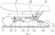
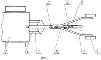
Сущность заявляемого устройства пояснена чертежами, где на фиг.1 дан общий вид устройства при минимальных нагрузках, изгибающих раму тягача; на фиг.2 устройство изображено при максимальной догрузке тягача; на фиг.3 приведен вид устройства сверху.The essence of the claimed device is illustrated by drawings, where in Fig. 1 a general view of the device is given at minimum loads bending the tractor frame; figure 2, the device is shown at the maximum load of the tractor; figure 3 shows a top view of the device.
Устройство для буксировки самолетов включает тягач 1, водило 2 с подкосами 3 и тележку 4 с опорными колесами 5 (фиг.1). Водило 2 и подкосы 3 соединены с тягачом 1 вертикальными шарнирами 6 и 7, а с тележкой 4 - поперечным шарниром 8. Для подъема передней стойки 9 шасси самолета на тележке 4 смонтирован механизм подъема 10 (фиг.2), включающий шарнирно закрепленный к тележке 4 рычаг 11, снабженный вилкообразным захватом 12 (фиг.3) и управляемый гидроцилиндром 13. Между тележкой 4 и тягачом 1 установлен гидроцилиндр 14, присоединенный к тягачу 1 универсальным шарниром 15. Опорные колеса 5 установлены с возможностью изменения длины тележки 4 за счет перестановки фиксирующих пальцев 16.A device for towing aircraft includes a
Устройство работает следующим образом. Устройство предусматривает два режима буксирования: буксирование по чистому покрытию, обладающему высоким коэффициентом сцепления, и буксирование по заснеженному покрытию с низким коэффициентом сцепления, особенно при начале движения.The device operates as follows. The device has two towing modes: towing on a clean cover with a high grip coefficient, and towing on a snowy cover with a low grip coefficient, especially when starting to move.
В первом случае до начало буксирования проверяют, находится ли гидроцилиндр 14 в плавающем положении (если нет, то устанавливают гидроцилиндр 14 в плавающее положение). Затем устанавливают необходимую длину тележки 4 за счет перестановки фиксирующих пальцев 16 (фиг.1), которая обеспечивает достаточный сцепной вес тягачу для буксирования самолета с конкретным взлетным весом. Затем тягач 1 подъезжает к самолету так, чтобы его передняя стойка 9 шасси оказалась вблизи вилкообразного захвата 12 (фиг.3), и производят захват передней стойки 9 шасси вилкообразным захватом 12 и посредством механизма подъема 10 производят гидроцилиндром 13 подъем передней стойки 9 шасси до полного отрыва от опорной поверхности. После чего гидроцилиндр 13 запирают на все время буксирования самолета.In the first case, before towing starts, it is checked whether the
После вывешивания передней стойки 9 шасси ее вес распределяется между опорными колесами 5 и поперечным шарниром 8 обратно пропорционально их расстоянию от передней стойки 9 шасси (плечи «b-a» и «c», фиг.1). Вертикальная нагрузка R, действующая на поперечный шарнир 8, меньше веса, приходящегося на переднюю стойку 9 шасси Gcm, и целиком передается на тягач 1, увеличивая его сцепной вес. При этом существенно уменьшается изгибающий момент, действующий на тягач 1 (как за счет уменьшения консоли «а<б», так и за счет меньшей величины догрузки «R<Gcm»).After hanging the
Движение тягач 1 начинает с увеличенным сцепным весом, при минимальных изгибающих его раму нагрузках. Динамические нагрузки при начале движения тягача 1, в ходе транспортирования и при торможении воспринимаются водилом 2, которое выполнено в виде двустороннего амортизатора. Наличие в устройстве вертикальных шарниров 6 и 7 обеспечивает высокую маневренность при буксировании. Все отмеченные особенности повышают эксплуатационные качества буксировщика.The movement of the
Буксирование по заснеженному покрытию с низким коэффициентом сцепления, особенно при начале движения, требует большего сцепного веса тягача. Поэтому перед началом буксировки максимально удлиняют длину тележки 4 за счет перестановки фиксирующих пальцев 16. Затем увеличивают сцепной вес тягача 1 описанным выше образом и с помощью гидроцилиндра 14 приподнимают тележку 4 вместе с передней стойкой 9 шасси до отрыва опорных колес 5 (появляется зазор «d», фиг.2), поворачивая тележку 4 относительно поперечного шарнира 8. В этом случае догрузка тягача 1 добавочным сцепным весом становится максимальной («R=Gcm»), тягач 1 преодолевает участок с низким коэффициентом сцепления, однако в это время на тягач 1 действует максимальный изгибающий момент («R×в»). После преодоления такого участка (или после набора скорости) гидроцилиндр 14 переводят в плавающее положение, догрузка тягача и изгибающие нагрузки становятся меньше («a<в», «R<Gcm», фиг.1).Towing on a snowy coating with a low coefficient of adhesion, especially at the start of driving, requires a greater grip of the tractor. Therefore, before towing begins, the length of the trolley 4 is maximally lengthened by shifting the
Предлагаемое устройство позволяет осуществлять буксирование самолетов с разной степенью увеличения их сцепного веса без затрат на это дополнительной энергии двигателя и при минимальных изгибающих нагрузках. Возможна кратковременная работа при максимальной догрузке тягача и значительных изгибающих тягач нагрузках. В целом устройство обеспечивает при работе буксировщика минимальные энергетические затраты и рациональное нагружение его трансмиссии и металлоконструкций.The proposed device allows towing aircraft with varying degrees of increase in their grip weight without the expense of additional engine energy and with minimal bending loads. Short-term operation is possible with maximum loading of the tractor and significant bending tractor loads. In general, the device provides the towing vehicle with minimal energy costs and rational loading of its transmission and metal structures.
Claims (3)
Priority Applications (1)
| Application Number | Priority Date | Filing Date | Title |
|---|---|---|---|
| RU2010140183/11A RU2450958C1 (en) | 2010-09-30 | 2010-09-30 | Aircraft towing device |
Applications Claiming Priority (1)
| Application Number | Priority Date | Filing Date | Title |
|---|---|---|---|
| RU2010140183/11A RU2450958C1 (en) | 2010-09-30 | 2010-09-30 | Aircraft towing device |
Publications (2)
| Publication Number | Publication Date |
|---|---|
| RU2010140183A RU2010140183A (en) | 2012-04-10 |
| RU2450958C1 true RU2450958C1 (en) | 2012-05-20 |
Family
ID=46031357
Family Applications (1)
| Application Number | Title | Priority Date | Filing Date |
|---|---|---|---|
| RU2010140183/11A RU2450958C1 (en) | 2010-09-30 | 2010-09-30 | Aircraft towing device |
Country Status (1)
| Country | Link |
|---|---|
| RU (1) | RU2450958C1 (en) |
Cited By (2)
| Publication number | Priority date | Publication date | Assignee | Title |
|---|---|---|---|---|
| CN106240834A (en) * | 2016-07-29 | 2016-12-21 | 安庆米锐智能科技有限公司 | A kind of unmanned plane landing platform based on parallel institution |
| CN110615116A (en) * | 2019-09-29 | 2019-12-27 | 北京航瑞达科技有限公司 | Novel electric traction device of double-rudder hydraulic steering clamp type for airplane |
Citations (6)
| Publication number | Priority date | Publication date | Assignee | Title |
|---|---|---|---|---|
| SU234162A1 (en) * | Г. А. Леонтьев | DEVICE FOR DETERMINATION WITH EXPLOSIVE-LANDING BAND OF A PLANE WITH DESTRUCTURED POLISHING [SCAMWAY | ||
| US3662911A (en) * | 1970-03-20 | 1972-05-16 | Donald A Harman | Towing device |
| US4130210A (en) * | 1977-08-04 | 1978-12-19 | Purviance John R | Self-propelled airplane dolly |
| DE4426519A1 (en) * | 1994-07-27 | 1996-02-08 | Jaegeler Gmbh | Towing equipment for medium size aircraft which have undercarriage and nose=wheel |
| RU2316454C1 (en) * | 2006-04-27 | 2008-02-10 | Государственное образовательное учреждение высшего профессионального образования Воронежское высшее военное авиационное инженерное училище (военный институт) | Facility for aircraft evacuation |
| RU2361786C1 (en) * | 2008-04-09 | 2009-07-20 | Государственное образовательное учреждение высшего профессионального образования "Воронежское высшее военное авиационное инженерное училище (военный институт)" Министерства обороны Российской Федерации | Aircraft towing device |
-
2010
- 2010-09-30 RU RU2010140183/11A patent/RU2450958C1/en not_active IP Right Cessation
Patent Citations (6)
| Publication number | Priority date | Publication date | Assignee | Title |
|---|---|---|---|---|
| SU234162A1 (en) * | Г. А. Леонтьев | DEVICE FOR DETERMINATION WITH EXPLOSIVE-LANDING BAND OF A PLANE WITH DESTRUCTURED POLISHING [SCAMWAY | ||
| US3662911A (en) * | 1970-03-20 | 1972-05-16 | Donald A Harman | Towing device |
| US4130210A (en) * | 1977-08-04 | 1978-12-19 | Purviance John R | Self-propelled airplane dolly |
| DE4426519A1 (en) * | 1994-07-27 | 1996-02-08 | Jaegeler Gmbh | Towing equipment for medium size aircraft which have undercarriage and nose=wheel |
| RU2316454C1 (en) * | 2006-04-27 | 2008-02-10 | Государственное образовательное учреждение высшего профессионального образования Воронежское высшее военное авиационное инженерное училище (военный институт) | Facility for aircraft evacuation |
| RU2361786C1 (en) * | 2008-04-09 | 2009-07-20 | Государственное образовательное учреждение высшего профессионального образования "Воронежское высшее военное авиационное инженерное училище (военный институт)" Министерства обороны Российской Федерации | Aircraft towing device |
Cited By (2)
| Publication number | Priority date | Publication date | Assignee | Title |
|---|---|---|---|---|
| CN106240834A (en) * | 2016-07-29 | 2016-12-21 | 安庆米锐智能科技有限公司 | A kind of unmanned plane landing platform based on parallel institution |
| CN110615116A (en) * | 2019-09-29 | 2019-12-27 | 北京航瑞达科技有限公司 | Novel electric traction device of double-rudder hydraulic steering clamp type for airplane |
Also Published As
| Publication number | Publication date |
|---|---|
| RU2010140183A (en) | 2012-04-10 |
Similar Documents
| Publication | Publication Date | Title |
|---|---|---|
| US7377398B2 (en) | Portable knockdown trolley hoist | |
| US8182193B2 (en) | Trailer for transporting freight containers and method of use | |
| US5701966A (en) | Omnidirectional self-propelled vehicle for ground handling of equipment | |
| US8066467B2 (en) | Omni-directional towbarless aircraft transporter for moving aircraft | |
| AU623115B2 (en) | Aircraft ground handling vehicle | |
| US8967939B2 (en) | Aircraft transporter dolly with hinged gate for moving aircraft | |
| CN104843038A (en) | Cart with extension-type wheels | |
| US5150860A (en) | Air vehicle launching device | |
| US8636461B2 (en) | Omni-directional aircraft transporter with hinged gate for moving aircraft | |
| RU2450958C1 (en) | Aircraft towing device | |
| US9011073B2 (en) | Truck loading device | |
| CN108996232A (en) | A kind of luggage elevator device people | |
| CN201842613U (en) | Accompanying type self-loading and self-unloading electric forklift | |
| CN210116428U (en) | Electric power emergency car | |
| WO2010082842A1 (en) | Improved trailer having adjustable elevation | |
| RU2483988C1 (en) | Small-size device for aircraft towing | |
| CN205221135U (en) | Auxiliary device is removed on sled formula helicopter semi -mounted type ground | |
| RU2294863C2 (en) | Method of transportation of aircraft | |
| RU2316454C1 (en) | Facility for aircraft evacuation | |
| CN202944246U (en) | Helicopter transshipment semi-trailer | |
| US20130315696A1 (en) | Vehicle Chassis | |
| CN102390784A (en) | Hoist frame winch transport vehicle | |
| RU2487061C1 (en) | Aircraft tractor unit | |
| RU2511236C2 (en) | Method of aircraft towing | |
| AU2008101058A4 (en) | A wheel stillage |
Legal Events
| Date | Code | Title | Description |
|---|---|---|---|
| MM4A | The patent is invalid due to non-payment of fees |
Effective date: 20131001 |