RU2433355C1 - Electric heater box for radiator space heater - Google Patents
Electric heater box for radiator space heater Download PDFInfo
- Publication number
- RU2433355C1 RU2433355C1 RU2010142384/03A RU2010142384A RU2433355C1 RU 2433355 C1 RU2433355 C1 RU 2433355C1 RU 2010142384/03 A RU2010142384/03 A RU 2010142384/03A RU 2010142384 A RU2010142384 A RU 2010142384A RU 2433355 C1 RU2433355 C1 RU 2433355C1
- Authority
- RU
- Russia
- Prior art keywords
- box
- heater block
- fitting
- tank
- hot water
- Prior art date
Links
- XLYOFNOQVPJJNP-UHFFFAOYSA-N water Substances O XLYOFNOQVPJJNP-UHFFFAOYSA-N 0.000 claims abstract description 101
- 238000010438 heat treatment Methods 0.000 claims abstract description 55
- 238000000926 separation method Methods 0.000 claims description 54
- 230000007704 transition Effects 0.000 claims description 4
- 230000009471 action Effects 0.000 abstract description 3
- 230000000694 effects Effects 0.000 abstract description 3
- 238000012546 transfer Methods 0.000 abstract description 3
- 230000005611 electricity Effects 0.000 abstract description 2
- 238000009435 building construction Methods 0.000 abstract 1
- 238000004064 recycling Methods 0.000 abstract 1
- 239000000126 substance Substances 0.000 abstract 1
- 239000000446 fuel Substances 0.000 description 8
- 210000002445 nipple Anatomy 0.000 description 7
- 239000004033 plastic Substances 0.000 description 7
- 210000001991 scapula Anatomy 0.000 description 7
- 229910000831 Steel Inorganic materials 0.000 description 6
- 238000009434 installation Methods 0.000 description 6
- 239000010959 steel Substances 0.000 description 6
- 238000012423 maintenance Methods 0.000 description 5
- 229920000181 Ethylene propylene rubber Polymers 0.000 description 4
- 230000001174 ascending effect Effects 0.000 description 4
- 238000010276 construction Methods 0.000 description 4
- 238000013461 design Methods 0.000 description 3
- 229920001971 elastomer Polymers 0.000 description 3
- 239000002360 explosive Substances 0.000 description 3
- 230000020169 heat generation Effects 0.000 description 3
- 239000003351 stiffener Substances 0.000 description 3
- RYGMFSIKBFXOCR-UHFFFAOYSA-N Copper Chemical compound [Cu] RYGMFSIKBFXOCR-UHFFFAOYSA-N 0.000 description 2
- 229920002943 EPDM rubber Polymers 0.000 description 2
- 239000007864 aqueous solution Substances 0.000 description 2
- 229910052802 copper Inorganic materials 0.000 description 2
- 239000010949 copper Substances 0.000 description 2
- 238000010586 diagram Methods 0.000 description 2
- 238000007599 discharging Methods 0.000 description 2
- 239000002184 metal Substances 0.000 description 2
- 229910052751 metal Inorganic materials 0.000 description 2
- 230000001681 protective effect Effects 0.000 description 2
- 230000008439 repair process Effects 0.000 description 2
- 239000002904 solvent Substances 0.000 description 2
- 239000011248 coating agent Substances 0.000 description 1
- 238000000576 coating method Methods 0.000 description 1
- 239000002274 desiccant Substances 0.000 description 1
- 239000007789 gas Substances 0.000 description 1
- 238000009499 grossing Methods 0.000 description 1
- 230000017525 heat dissipation Effects 0.000 description 1
- 239000011261 inert gas Substances 0.000 description 1
- 238000007689 inspection Methods 0.000 description 1
- 239000011810 insulating material Substances 0.000 description 1
- 238000003754 machining Methods 0.000 description 1
- 238000000034 method Methods 0.000 description 1
- 239000000203 mixture Substances 0.000 description 1
- 239000002991 molded plastic Substances 0.000 description 1
- 238000011022 operating instruction Methods 0.000 description 1
- 230000008569 process Effects 0.000 description 1
- 238000012545 processing Methods 0.000 description 1
- 230000009467 reduction Effects 0.000 description 1
- 238000003303 reheating Methods 0.000 description 1
- 230000003014 reinforcing effect Effects 0.000 description 1
- 230000002269 spontaneous effect Effects 0.000 description 1
- 229910001220 stainless steel Inorganic materials 0.000 description 1
- 239000010935 stainless steel Substances 0.000 description 1
- 238000007751 thermal spraying Methods 0.000 description 1
Images


Classifications
-
- F—MECHANICAL ENGINEERING; LIGHTING; HEATING; WEAPONS; BLASTING
- F24—HEATING; RANGES; VENTILATING
- F24H—FLUID HEATERS, e.g. WATER OR AIR HEATERS, HAVING HEAT-GENERATING MEANS, e.g. HEAT PUMPS, IN GENERAL
- F24H3/00—Air heaters
- F24H3/002—Air heaters using electric energy supply
- F24H3/004—Air heaters using electric energy supply with a closed circuit for a heat transfer liquid
-
- F—MECHANICAL ENGINEERING; LIGHTING; HEATING; WEAPONS; BLASTING
- F24—HEATING; RANGES; VENTILATING
- F24D—DOMESTIC- OR SPACE-HEATING SYSTEMS, e.g. CENTRAL HEATING SYSTEMS; DOMESTIC HOT-WATER SUPPLY SYSTEMS; ELEMENTS OR COMPONENTS THEREFOR
- F24D19/00—Details
- F24D19/06—Casings, cover lids or ornamental panels, for radiators
-
- F—MECHANICAL ENGINEERING; LIGHTING; HEATING; WEAPONS; BLASTING
- F24—HEATING; RANGES; VENTILATING
- F24D—DOMESTIC- OR SPACE-HEATING SYSTEMS, e.g. CENTRAL HEATING SYSTEMS; DOMESTIC HOT-WATER SUPPLY SYSTEMS; ELEMENTS OR COMPONENTS THEREFOR
- F24D3/00—Hot-water central heating systems
- F24D3/10—Feed-line arrangements, e.g. providing for heat-accumulator tanks, expansion tanks ; Hydraulic components of a central heating system
- F24D3/1008—Feed-line arrangements, e.g. providing for heat-accumulator tanks, expansion tanks ; Hydraulic components of a central heating system expansion tanks
Landscapes
- Engineering & Computer Science (AREA)
- Physics & Mathematics (AREA)
- Thermal Sciences (AREA)
- Chemical & Material Sciences (AREA)
- Combustion & Propulsion (AREA)
- Mechanical Engineering (AREA)
- General Engineering & Computer Science (AREA)
- Steam Or Hot-Water Central Heating Systems (AREA)
- Domestic Hot-Water Supply Systems And Details Of Heating Systems (AREA)
- Housings, Intake/Discharge, And Installation Of Fluid Heaters (AREA)
- Central Heating Systems (AREA)
Abstract
Description
Настоящее изобретение относится к коробке блока электронагревателя, содержащей коробку для размещения единиц разного рода оборудования, используемого после подключения к радиатору с циркуляцией горячей воды для внутреннего отопления и, в частности, для внутреннего отопления здания.The present invention relates to a box of an electric heater block containing a box for accommodating units of various kinds of equipment used after connecting to a radiator with hot water circulation for internal heating and, in particular, for internal heating of a building.
Существуют различные типы внутренних систем водяного отопления, типичные примеры которых представлены на фиг. 6, иллюстрирующей пример 1 предшествующего уровня техники, и на фиг. 7, иллюстрирующей пример 2 предшествующего уровня техники. Пример 1 предшествующего уровня техники на фиг. 6 представляет собой типичную внутреннюю систему водяного отопления, рассматриваемую в непатентном документе 1, причем на фиг. 6(A) представлен общий схематический вид системы, на фиг. 6(B) - вид спереди тепловыделяющей секции системы отопления, а фиг. 6(C) - вид сбоку тепловыделяющей секции.There are various types of domestic water heating systems, typical examples of which are shown in FIG. 6 illustrating prior art example 1, and in FIG. 7 illustrating example 2 of the prior art. Prior art example 1 in FIG. 6 is a typical internal water heating system discussed in
В частности, в случае примера 1 предшествующего уровня техники (фиг. 6) бойлер 100, снабженный с манометром 103, предохранительно-разгрузочным клапаном, отверстием 101 для впуска воды и отверстием 102 для выпуска воды, подвергается нагреву электричеством, газом и т.д., через трубопровод P и выходной коллектор 107 горячая вода, нагретая в бойлере 100, подается в радиатор HR металлической панели MP, размещенной в отдельных жилых комнатах, для внутреннего обогрева и затем возвращается из отдельных радиаторов HR через трубопровод P и возвратный коллектор 108 в бойлер 100 для повторного нагрева. В функциональном блоке циркуляции горячей воды установлены циркуляционный насос 104, закрытый расширительный бачок 105, выпускной воздушный клапан, коллекторы 107, 108 и т.д., а в отдельных радиаторах HR размещены выпускной воздушный клапан Va, клапан Vt термостата и вентиль V впуска/выпуска горячей воды. Таким образом, система отопления подключена к большому числу радиаторов HR через одну систему циркуляции горячей воды, размещенной в центре системы отопления.In particular, in the case of Example 1 of the prior art (FIG. 6), the
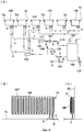
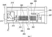
Пример 2 предшествующего уровня техники (фиг. 7) относится к электрическому бойлеру EHR, рассматриваемому в патентном документе 1. Как показано на фиг. 7, электрический бойлер EHR представляет собой нагреватель с большим числом теплоизлучающих ребер 202, размещенных на внешней поверхности нагревательной медной трубы 201, с нагревательным элементом 204 в кожухе, установленным в нагревательной камере 203, заполненной водным раствором 205, внутри нагревательной медной трубы 201 практически вдоль всей ее длины, и с расширительной комнатной трубой 206, проходящей от нагревательной камеры 203 через коленчатый патрубок 207 и формирующей, таким образом, расширительную камеру 208 с клапаном 209 сброса давления на конце. В расширительную камеру 208 закачан инертный газ, что в результате объединения нагревательной и тепловыделяющей секций одной с другой позволяет минимизировать размеры нагревателя в целом и ускорить разогрев теплоизлучающих ребер 202 на начальном этапе работы бойлера.Prior art Example 2 (FIG. 7) relates to an EHR electric boiler as described in
Позиция 210 обозначает коробку с термостатом 211 и переключателем 212 предохранения от перегрева.
Патентный документ l:JP 6-18813 YPatent Document l: JP 6-18813 Y
Непатентный документ l: Главы "Меры предосторожности при проектировании, установке и эксплуатации" и "Инструкции по эксплуатации термопанелей" в рекламном буклете (№ 0402-5C-dB) "Техническая документация по панельным системам водяного отопления Моринага" компании Morinaga Engineering Co., Ltd.Non-Patent Document l: Chapters "Precautions for Design, Installation and Operation" and "Operating Instructions for Thermal Panels" in leaflet (No. 0402-5C-dB) "Technical Documentation for Morinaga Panel Water Heating Systems" by Morinaga Engineering Co., Ltd .
Система отопления с циркуляцией горячей воды, рассмотренная в примере 1 предшествующего уровня техники (фиг. 6), является одной из систем отопления с циркуляцией горячей воды, содержащей бойлер 100, снабженный предохранительно-разгрузочным клапаном, манометром, перепускным клапаном для выпуска воды и перепускным клапаном для подачи воды, закрытый расширительный бачок 105, снабженный предохранительно-разгрузочным клапаном, выходным коллектором и возвратным коллектором, насос для циркуляции горячей воды, воздухоотделитель 110, размещенный между бойлером и насосом для циркуляции горячей воды и снабженный выпускным воздушным клапаном, и группу из большого числа радиаторов HR, размещенных в соответствующих камерах и подключенных один к другому перед началом работы системы отопления через трубопровод. Так как бойлер находится в одной камере и соединяется с каждым из радиаторов HR через трубопровод, проходящий под полом, через стены и в потолке, то существуют следующие проблемы.The heating system with hot water circulation, described in Example 1 of the prior art (Fig. 6), is one of the heating systems with hot water circulation containing a
(A) В случае использования системы централизованного управления трубопровод P для подключения системы отопления с циркуляцией горячей воды к соответствующим группам радиаторов, распределенным по помещениям, устанавливают при постройке нового здания в стенах, под полом и в потолке, в результате чего устранение повреждения водопроводных линий для горячей воды (от системы отопления с циркуляцией горячей воды до соответствующих радиаторов HR) или их ремонт в течение срока эксплуатации включает в себя работы, выполняемые под полом, в стенах и в потолке, требующие времени и расходов.(A) In the case of using a centralized control system, the P pipeline for connecting a heating system with hot water circulation to the corresponding groups of radiators distributed throughout the rooms is installed during the construction of a new building in the walls, under the floor and in the ceiling, as a result of which the damage to the water supply lines for hot water (from a heating system with hot water circulation to the corresponding HR radiators) or their repair during the operation period includes work performed under the floor, in the walls and in the ceiling, requiring time and expense.
(B) Поломка циркуляционного насоса и т.д. в системе отопления с циркуляцией горячей воды ведет к прекращению работы всей системы отопления.(B) Circulation pump failure, etc. in a heating system with circulation of hot water leads to the cessation of the entire heating system.
(C) Соединительный трубопровод от системы циркуляции до соответствующих комнат вследствие выделения теплоты в водопроводных линиях для горячей воды имеет большие тепловые потери.(C) The connecting pipe from the circulation system to the respective rooms, due to heat generation in the hot water pipes, has large heat losses.
В случае электрического бойлера, рассматриваемого в примере 2 предшествующего уровня техники (фиг. 7), водный раствор в нагревательном элементе 204, заключенном в кожух, подвергается только нагреву, и горячая вода не совершает циркуляции, что ведет к возникновению локальных участков нагрева и обусловливает малое тепловыделение.In the case of the electric boiler described in Example 2 of the prior art (Fig. 7), the aqueous solution in the
Кроме того, так как выделение тепла для отопления в этом случае связано с естественной конвекцией, то это ведет к возникновению участков нагрева, определяемых положением тепловыделяющих участков, и обеспечить равномерность отопления по всей поверхности тепловыделяющей секции невозможно.In addition, since the heat generation for heating in this case is associated with natural convection, this leads to the appearance of heating sections determined by the position of the fuel sections, and it is impossible to ensure uniform heating across the entire surface of the fuel section.
Кроме того, объединение нагревательной и тепловыделяющей секций одной с другой обусловливает повышение частоты операций включения/выключения источника электропитания, работой которого управляет термостат, что ведет к снижению эффективности тепловыделения в зависимости мощности.In addition, the combination of the heating and fuel sections of one with the other leads to an increase in the frequency of operations on / off of the power source, the operation of which is controlled by a thermostat, which leads to a decrease in the efficiency of heat generation depending on power.
Настоящее изобретение позволяет решить проблемы предшествующего уровня техники или усовершенствовать рассмотренные примеры, и для этого предлагается электрическая система циркуляции горячей воды, размещенная в коробке блока нагревателя, устанавливаемой отдельно и независимо от радиатора, являющейся компактной по размерам и, таким образом, позволяющей свободно переносить, размещать или устанавливать эту электрическую систему циркуляции горячей воды и осуществлять эти действия беспрепятственно как при строительстве нового здания, так и при перестройке уже имеющегося.The present invention allows to solve the problems of the prior art or to improve the examples considered, and for this an electric hot water circulation system is proposed, which is located in a box of a heater block, which is installed separately and independently of a radiator, which is compact in size and, thus, allowing free transfer, placement or install this electric hot water circulation system and carry out these actions without hindrance as in the construction of a new building, ak and in the restructuring of an existing one.
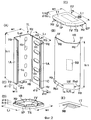
Коробка блока электронагревателя согласно изобретению содержит коробку 1 блока нагревателя, например, в форме длинномерного полигонального цилиндра 1K, показанного на фиг. 1, с возможностью свободного открывания или закрывания крышками 1D, 1U, надетыми на его соответствующие торцы, где внутри коробки 1 блока нагревателя размещены функциональные блоки секции циркуляции горячей воды, представляющие собой воздухоотделительный бачок 2 высокого давления, циркуляционный насос 3 и трубчатые нагреватели 4, соединенные один с другим посредством трубопроводного соединения с помощью труб через шаровые клапаны 6A, 6B, 6C и тройники 7, 7A с возможностью обеспечения, таким образом, подключения коробки 1 блока нагревателя к радиатору с циркуляцией горячей воды для внутреннего отопления, причем как показано на фиг. 2 и фиг. 3, полигональный цилиндр 1K состоит из длинномерных левого и правого листов 1L, 1R, имеющих L-образную форму сечения, образующих разъемное соединение один с другим, и на одной боковой стороне Ls1 левого листа 1L с L-образной формой сечения имеется большое число отверстий H1 для кабелей, выполненных в вертикальном направлении на равном расстоянии одно от другого, а на другой боковой стороне Ls2 левого листа 1L имеется большое число отверстий H3 для циркуляции воздуха, выполненных на участках, соответствующих соответствующим отверстиям H1 для кабелей.The box of the electric heater block according to the invention comprises a
В этом случае достаточно лишь обеспечить штуцером каждую из выходящих труб, идущих к радиатору (подводящих труб), и каждую из труб, идущих от радиатора (возвратных труб), на соответствующих участках коробка 1 блока нагревателя.In this case, it is enough to provide a fitting for each of the outgoing pipes going to the radiator (supply pipes), and each of the pipes coming from the radiator (return pipes), in the corresponding sections,
Кроме того, каждый из составных компонентов коробки блока электронагревателя, таких как циркуляционный насос 3, трубчатые нагреватели 4, шаровые клапаны 6A, 6B, 6C и тройники 7, 7A выполнены как обычные компоненты, а воздухоотделительный бачок 2 высокого давления представляет собой новый компонент с функциями расширительного бачка и воздухоотделителя, описываемыми в примере 1 предшествующего уровня техники, и трубы для трубопровода изготовлены из этилен-пропиленового каучука, отличающегося износоустойчивостью, термостойкостью и стойкостью к действию растворителей.In addition, each of the components of the box of the electric heater block, such as the
Кроме того, в предпочтительном варианте в качестве предпочтительного трубчатого нагревателя 4 может быть использован нагреватель SC (торговая марка) компании Нэцусе К.К. для выработки тепла на 1 кВт, отличающийся своими энергосберегающими характеристиками, причем в зависимости от тепловой мощности трубчатого нагревателя 4 таких нагревателей может быть несколько.In addition, in a preferred embodiment, as the preferred
Следовательно, если коробка блока электронагревателя согласно изобретению используется для универсального нагревателя мощностью 1-3 кВт, то эта коробка блока электронагревателя представляет собой коробку 1 блока нагревателя малых размеров (стандартные значения: 180 мм (ширина)×160 мм (глубина)×590 мм (длина)), которая может быть размещена или в горизонтальном положении, как показано на фиг. 1, или в вертикальном положении (не показанном) и установлена рядом с отдельно стоящим радиатором с циркуляцией горячей воды, и поэтому трубопроводное соединение от коробки 1 блока нагревателя к радиатору может быть выполнено на близком расстоянии, например, в пределах одной комнаты, а тепло, выделяющееся из трубопроводного соединения, может быть использовано для частичного внутреннего отопления, и обеспечить, таким образом, создание системы отопления, работающей за счет циркуляции горячей воды, с практически нулевыми тепловыми потерями.Therefore, if the box of the electric heater block according to the invention is used for a universal heater with a power of 1-3 kW, then this box of the electric heater block is a
Кроме того, так как функциональный блок циркуляции горячей воды представляет собой компактную коробку в форме полигонального цилиндра, то этот функциональный блок обладает высокой гибкостью с точки зрения возможности его размещения внутри помещения, и при условии размещения рядом с разъемом источника электропитания возможно свободное размещение коробки блока электронагревателя независимо от того, осуществляется ли это при строительстве нового здания или при перестройке уже имеющегося.In addition, since the hot water circulation functional block is a compact box in the form of a polygonal cylinder, this functional block is highly flexible in terms of being able to be placed indoors, and provided that the electric heater box can be freely placed next to the power supply connector regardless of whether it is carried out during the construction of a new building or during the reconstruction of an existing one.
Поэтому даже в случае, например, здания с системой водяного отопления, рассматриваемой в примере 1 предшествующего уровня техники (фиг. 6), при перестройке старый трубопровод может быть оставлен под полом, в стенах и в потолке, и при условии размещения каждой коробки блока электронагревателя согласно изобретению с соблюдением соотношения 1:1 с каждым из радиаторов или 1:2 с каждыми двумя соседними радиаторами возможно создание внутренней системы водяного отопления с тепловыделяющей секцией и секцией циркуляции горячей воды, установленными одна отдельно от другой, обладающей высокой работоспособностью и высокой ремонтопригодностью.Therefore, even in the case of, for example, a building with a water heating system, considered in Example 1 of the prior art (Fig. 6), during reconstruction, the old pipeline can be left under the floor, in the walls and in the ceiling, and provided that each box of the electric heater block is placed according to the invention in compliance with a ratio of 1: 1 with each of the radiators or 1: 2 with every two adjacent radiators, it is possible to create an internal water heating system with a fuel section and a hot water circulation section installed bottom separately from each other, having high workability and high maintainability.
Кроме того, согласно настоящему изобретению, как показано, например, на фиг. 2 и 3, коробка 1 блока нагревателя содержит длинномерный полигональный цилиндр 1K, образованный в результате разъемного соединения длинномерных левого и правого листов 1L, 1R, имеющих L-образную форму сечения, одного с другим, а также съемные верхнюю и нижнюю крышки 1U и 1D, надетые на соответствующие торцы полигонального цилиндра 1K, причем в предпочтительном варианте на одной боковой стороне Ls1 левого листа 1L имеется большое число отверстий H1 для кабелей, выполненных в вертикальном направлении на равном расстоянии одно от другого, а на другой боковой стороне Ls2 левого листа 1L имеются отверстия H3 для циркуляции воздуха, выполненные на участках, соответствующих отверстиям H1 для кабелей.In addition, according to the present invention, as shown, for example, in FIG. 2 and 3, the
В этом случае левый лист 1L со стороны своей внутренней поверхности крепится на несущей стойке для единиц разного рода оборудования, а правый лист 1R используется в качестве крышки для полигонального цилиндра 1K.In this case, the
Кроме того, отверстия H1 для кабелей могут быть использованы для обеспечения размещения в соответствующем положении проводного соединения между электромонтажной коробкой (не показанной), предварительно встроенной в поверхность стены WL или в поверхность пола FL, и блоком регулирования температуры (не показанным), размещаемым в коробке блока нагревателя, размеры отверстий H1 для кабелей позволяют человеку вводить в них свою руку, а сами отверстия шириной 60 мм и высотой 40 мм имеют, как правило, продолговатую форму и размещены на пяти участках боковой стороны Ls1 на одинаковом расстоянии одно от другого, составляющем 100 мм.In addition, cable holes H1 can be used to ensure that the wire connection between the wiring box (not shown) pre-integrated into the wall surface WL or the floor surface FL and the temperature control unit (not shown) placed in the box is in an appropriate position heater block, the hole sizes H1 for cables allow a person to enter his hand into them, and the holes themselves are 60 mm wide and 40 mm high, as a rule, have an oblong shape and are located in five sections b the shackle side Ls1 at the same distance from one another, amounting to 100 mm.
Отверстия H3 для циркуляции воздуха обеспечивают рассеяние тепла, выделяющегося в коробке 1 блока нагревателя, наружу и, следовательно, создание в коробке 1 блока нагревателя потока воздуха, причем эти отверстия имеют, как правило, продолговатую форму, а их ширина и высота составляют соответственно 20 мм и 40 мм.The air circulation openings H3 ensure that the heat released in
При размещении коробки 1 блока нагревателя в вертикальном положении панель 9B управления может быть установлена на верхней крышке 1U, а при размещении коробки 1 блока нагревателя в горизонтальном положении панель 9B управления может быть установлена на правом листе 1R, служащем крышкой полигонального цилиндра 1K.When the
Следовательно, при снятии верхней и нижней крышек 1U, 1D полигональный цилиндр 1K может быть разобран на левый и правый листы 1L, 1R, имеющие L-образную форму сечения, и крепление единиц оборудования, подлежащих установке в коробке 1, может быть осуществлено только на левом листе 1L, что обеспечивает возможность беспрепятственного выполнения техобслуживания в коробке 1 блока нагревателя в результате простого убирания правого листа 1R, служащего крышкой полигонального цилиндра 1K.Therefore, when removing the upper and
Кроме того, что касается размещения коробки 1 блока нагревателя в соответствующих комнатах, то так как отверстия H1 выполнены одно за другим в несколько ярусов, то возможен выбор варианта положения соединения с электромонтажной коробкой, находящейся снаружи, что обеспечивает возможность размещения коробки 1 блока нагревателя в соответствующих комнатах без вреда для его внешнего вида.In addition, with regard to the placement of the
При этом, так как воздух в помещении, находящийся снаружи от коробки 1 блока нагревателя, может проходить как через отверстия H1 для кабелей, так и через отверстия H3 для циркуляции воздуха в коробке 1 блока нагревателя, то появляется возможность использования тепла, рассеиваемого после нагрева в коробке 1 блока нагревателя, для частичного внутреннего отопления, что позволяет создать систему отопления, работающую за счет циркуляции горячей воды, с практически нулевыми тепловыми потерями.Moreover, since the air in the room located outside of the
Кроме того, в коробке 1 блока нагревателя оба краевых участка левого листа 1L с L-образной формой сечения подвергнуты изгибу и образуют соответствующие угловые стороны 1A, как показано на фиг. 2 (A), а концы угловых сторон 1A образуют фиксаторы 1С с L-образной формой сечения, в то время как на обоих краевых участках правого листа 1R с L-образной формой сечения размещены опорные фиксаторы 1F, входящие в контакт с соответствующими фиксаторами 1C левого листа 1L, причем в предпочтительном варианте на верхнем и нижнем краевых участках левого и правого листов 1L, 1R с L-образной формой сечения выполнены соответствующие резьбовые отверстия H2, обеспечивающие крепление верхней и нижней крышек 1U, 1D с помощью винтов, ввинчиваемых в эти резьбовые отверстия H2 и в соответствующие резьбовые отверстия H2, выполненные на верхней и нижней крышках 1U, 1D.In addition, in
Левый и правый листы 1L, 1R, как правило, представляют собой стальные листы толщиной 1,2 мм, и для осуществления требуемого крепления соответствующих единиц оборудования, таких как шаровые клапаны, тройники, воздухоотделительного бачка высокого давления и т.д., к внутренней поверхности левого листа 1L посредством обыкновенной несущей стойки в предпочтительном варианте на соответствующих боковых сторонах Ls1, Ls2 и на угловых сторонах 1A размещены ребра 1G жесткости в форме выступов.The left and
Следовательно, появляется возможность беспрепятственной сборки-разборки коробки 1 блока нагревателя в результате соединения верхней и нижней крышек 1U, 1D с левым и правым листами 1L, 1R с помощью винтов, а также возможность крепления единиц разного рода оборудования только на левом листе 1L и беспрепятственного выполнения техобслуживания при проведении техосмотра, ремонтных работ, замены и т.д.Consequently, it becomes possible to freely assemble and disassemble the
Кроме того, наличие фиксаторов 1C и опорных фиксаторов 1F не только облегчает проведение операции повторного крепления правого листа, который убирается при техобслуживании, к левому листу 1L, но и позволяет использовать фиксаторы 1C и опорные 1F в качестве ребер жесткости коробки 1.In addition, the presence of
Кроме того, как показано на фиг. 5, воздухоотделительный бачок 2 высокого давления, размещенный в коробке 1 блока нагревателя, имеет форму коробки, содержащей нижнюю сторону 2D, переднюю сторону 2F, заднюю сторону 2B, верхнюю сторону 2T и боковые стороны 2L, 2R, где по наклонной стороне Sf верхняя сторона 2T постепенно переходит в переднюю сторону 2F, а по наклонной стороне Sb верхняя сторона 2T постепенно переходит в заднюю сторону 2B. В центре по вертикали на передней стороне 2F установлен штуцер Jl, в центре по вертикали на задней стороне 2B установлен штуцер J2, а в задней части верхней стороны 2T - штуцер J3. Между левой и правой боковыми сторонами 2L, 2R бачка 2 размещены две лопатки - передняя лопатка 2A и задняя лопатка 2A', расположенные с наклоном вверх в направлении назад, причем передняя лопатка 2A занимает низкое положение и размещена за штуцером J1, установленным на передней стороне 2F, а задняя лопатка 2A' занимает высокое положение и размещена под штуцером J3, установленным на верхней стороне 2T.Furthermore, as shown in FIG. 5, the high-pressure
В этом случае объем воздухоразделительного бачка 2 высокого давления может быть задан в результате вычисления на основе количества воды в системе отопления с циркуляцией при комнатной температуре (стандартное значение: 15°C), количества горячей воды (стандартное значение: 80°C) в системе отопления с циркуляцией после расширения и давления воздуха в баке 2, соответствующего количеству горячей воды при расширении. В предпочтительном варианте положения штуцеров J1, J2, J3 задают так, что даже при комнатной температуре при горизонтальном положении коробки 1 блока нагревателя в процессе использования штуцеры J1, J2 находятся ниже уровня воды, а при вертикальном положении коробки 1 блока нагревателя в процессе использования штуцеры J3, J2 находятся ниже уровня воды.In this case, the volume of the high-pressure
Кроме того, лопатка 2A, установленная в низком положении, и лопатка 2A', установленная в высоком положении, могут вызывать появление управляемых турбулентных потоков, которые могут быть использованы для усиления воздухоотделения, и если каждая из лопаток размещена с наклоном под углом 30°, то как при вертикальном, так и при горизонтальном положении бачка в процессе использования лопатки будут служить для подавления спонтанных вихревых потоков и в результате разделения потоков вызывать появление управляемых турбулентных потоков, которые могут быть использованы для усиления воздухоотделения.In addition, the
Воздухоотделительный бачок 2 высокого давления представляет собой бачок малых размеров, изготовленный из пластика, и в случае отсутствия необходимости выпускного воздушного и предохранительно-разгрузочного клапанов, как правило, представляет собой формованное изделие из пластика с толщиной стенок 0,6 мм, имеющее прочность (коэффициент запаса прочности), приблизительно в три раза превышающую взрывную прочность при высоком давлении в системе циркуляции. В случае радиатора мощностью 1 кВт при вертикальном положении воздухоотделительного бачка 2 высокого давления в процессе использования объем воды в нем и внутреннее давление в системе при комнатной температуре составляют соответственно 0,19 л (литров) и 0,01 МПа, а при температуре 80°C - соответственно 0,26 л и 0,04 МПа, в то время как при горизонтальном положении воздухотделительного бачка 2 высокого давления в процессе использования объем воды в нем и внутреннее давление в системе при комнатной температуре составляют соответственно 0,28 л и 0,01 мПа, а при температуре 80°C - соответственно 0,34 л и 0,04 МПа.The high-pressure
Случай, когда воздухоотделительный бачок 2 высокого давления выполнен из полупрозрачного пластика, обеспечивает возможность наблюдения за пространством внутри бачка снаружи и позволяет осуществлять визуальный контроль притока воды в этот бачок при заполнении системы отопления с циркуляцией водой, что создает определенные удобства при подготовке системы циркуляции к работе и при выполнении ее техобслуживания.The case when the high-pressure
Следовательно, в воздухотделительном бачке 2 высокого давления как при вертикальном, так и при горизонтальном его положении в процессе использования поток горячей воды внутри бачка 2 преобразуется в управляемые турбулентные потоки, эффективные для воздухоотделения с помощью двух лопаток - лопатки 2A и лопатки 2A', что в сочетании с резким снижением скорости потока горячей воды в бачке вызывает подъем воздушных пузырьков, находящихся в воде, вверх и их отделение и гарантирует сохранение воздуха, находящегося в системе циркуляции, внутри воздухоотделительного бачка 2 высокого давления. Для этого предлагается воздухоотделительный бачок высокого давления, размещаемый внутри системы циркуляции, без предохранительно-разгрузочного и выпускного воздушного клапанов, требуемых в случае примера 1 предшествующего уровня техники (фиг. 6), использование которого обеспечивает возможность размещения всей системы циркуляции, за исключением радиатора 6, рассматриваемого в примере 1 предшествующего уровня (фиг. 6), в одной коробке 1 блока нагревателя и позволяет использовать коробку 1 блока нагревателя как в вертикальном, так и в горизонтальном положении и гарантировать уменьшение размеров этой коробки.Therefore, in the high-pressure
Кроме того, в случае вертикального положения коробки 1 блока нагревателя согласно настоящему изобретению в форме полигонального цилиндра в процессе использования в предпочтительном варианте воздухоотделительный бачок 2 высокого давления размещают так, что передняя сторона 2F этого бачка располагается с верхней стороны коробки 1 блока нагревателя, а задняя сторона 2B - с нижней стороны коробки 1 блока нагревателя, штуцер J3 на верхней стороне 2T посредством трубопровода соединяется с трубчатым нагревателем 4, с соединительным отверстием J2 на задней стороне 2B соединяется выходная труба S, а штуцер J1 на передней стороне 2F закрывается заглушкой 2C.In addition, in the case of the vertical position of the
В этом случае циркуляционный насос 3 достаточно только установить и прикрепить к подставке 11 на нижней крышке 1D, служащей нижним основанием внутри коробки 1 блока нагревателя.In this case, the
Кроме того, соединение между штуцером J3 и трубчатым нагревателем 4 и соединение между выходной трубой S и штуцером J2 в предпочтительном варианте осуществляют с помощью трубы из этилен-пропиленового каучука (EPDM).In addition, the connection between the nozzle J3 and the
Следовательно, в воздухоотделительном бачке 2 высокого давления, как показано на фиг. 5(D), циркулирующая вода при комнатной температуре будет находиться на уровне wL1, а при температуре 80°C - на уровне wL2, поток Fin воды, втекающий через штуцер J3, превращается в поток Fout воды, вытекающий через штуцер J2. Внутри бачка 2 происходит резкое снижение скорости втекающего потока Fin воды и разделение этого потока с помощью нижней лопатки 2A', установленной внутри бачка 2 в низком положении, на восходящий и нисходящий потоки соответственно F1, F2, а с помощью верхней лопатки 2A, установленной внутри бачка 2 в высоком положении, и на восходящий и нисходящий потоки соответственно F3, F4, после чего происходит отделение воздушных пузырьков, находящихся в воде, и их подъем вверх в воздушную зону Za в верхней части бачка 2, закрытого заглушкой 2C, а горячая вода, не содержащая воздуха, получает возможность циркулировать из выходной трубы S коробки 1 блока нагревателя в тепловыделяющую секцию 8.Therefore, in the high pressure
Поэтому даже при вертикальном положении воздухоотделительного бачка 2 высокого давления согласно настоящему изобретению в процессе использования, как показано на фиг. 5(D), воздухоотделительный бачок 2 высокого давления выполняет функции закрытого расширительного бачка и воздухоотделителя, описываемых в примере 1 предшествующего уровня техники, что обеспечивает возможность уменьшения размеров коробки 1 блока нагревателя.Therefore, even with the upright position of the high-pressure
При этом в случае горизонтального положения коробки 1 блока нагревателя в форме полигонального цилиндра в процессе использования в предпочтительном варианте воздухоотделительный бачок 2 высокого давления размещают так, что верхняя сторона 2T воздухоотделительного бачка 2 высокого давления располагается с верхней стороны коробки 1 блока нагревателя, штуцер Jl на передней стороне 2F посредством трубопровода соединяется с трубчатым нагревателем 4, штуцер J2 на задней стороне 2B соединяется с выходной трубой S, а штуцер J3 на верхней стороне 2T закрывается заглушкой 2C.Moreover, in the case of the horizontal position of the
В этом случае, как показано на фиг. 4(C), циркуляционный насос 3 достаточно только установить и закрепить с помощью подставки 11 на одной боковой стороне Ls1 левого листа 1L, служащей нижним основанием внутри коробки 1 блока нагревателя.In this case, as shown in FIG. 4 (C), the
Кроме того, соединение между штуцером J3 и трубчатым нагревателем 4 и соединение между выходной трубой S и штуцером J2 в предпочтительном варианте осуществляют с помощью трубы из этилен-пропиленового каучука.In addition, the connection between the nozzle J3 and the
Так как штуцер J3 на верхней стороне 2T закрывают заглушкой 2C, то зона внутри бачка 2 под соединительным отверстием J3 становится воздушной зоной Za.Since the nozzle J3 on the
Следовательно, в воздухоотделительном бачке 2 высокого давления, как показано на фиг. 5(C), циркулирующая вода при комнатной температуре (15°C) будет находиться на уровне wL1, а при температуре 80°C - на уровне wL2, поток Fin воды, втекающий из трубчатого нагревателя 4, втекает через штуцер J1 внутрь бачка 2. Внутри бачка 2 происходит резкое снижение скорости втекающего потока воды и разделение этого потока с помощью передней лопатки 2A' на восходящий и нисходящий потоки F1, F2, после чего происходит отделение воздушных пузырьков, находящихся в воде, и их подъем вверх, а с помощью задней лопатки 2A' втекающий поток воды разделяется на восходящий и нисходящий потоки F3, F4 и превращается в вытекающий поток Fout воды, подаваемый через штуцер J2 на задней стороне 2B в выходную трубу S, при одновременном отделении и подъеме вверх воздушных пузырьков, выделяющихся из воды, в воздушную зону Za в верхней части бачка 2.Therefore, in the high pressure
Поскольку штуцер J3 на верхней стороне 2T закрыт заглушкой 2C, и в воздушной зоне Za в верхней части бачка 2 после нагрева и расширения циркулирующей воды устанавливается максимальное давление, не превышающее критической взрывной величины (стандартное значение: одна треть от значения взрывного давления), то даже при горизонтальном положении воздухоотделительного бачка 2 высокого давления в процессе использования, как показано на фиг. 5(C), этот воздухоотделительный бачок 2 высокого давления выполняет функции закрытого расширительного бачка и воздухоотделителя, описываемых в примере 1 предшествующего уровня техники, что обеспечивает возможность уменьшения размеров коробки 1 блока нагревателя.Since the nozzle J3 on the
Кроме того, в предпочтительном варианте, как показано, например, на фиг. 2, коробка 1 блока нагревателя содержит наклонную сторону 1R',сформированную на центральном угловом участке правого листа 1R, на боковой стороне Ls1 левого листа 1L по обе стороны от ряда отверстий H1 для кабелей размещены ребра 1G жесткости в форме выступов, а внутри коробки 1 блока нагревателя на внутренней поверхности одной боковой стороны Ls1 левого листа 1L закреплены единицы разного рода оборудования.Furthermore, in a preferred embodiment, as shown, for example, in FIG. 2, the
В этом случае крепление единиц оборудования, таких как циркуляционный насос 3, воздухоотделительный бачок 2 высокого давления, трубчатые нагреватели 4 и т.д., к левому листу 1L может быть осуществлено посредством выступающей несущей стойки в виде стального уголкового профиля, прикрепленной к обыкновенному стальному профилю желобообразной формы, который крепится к соответствующему участку боковой стороны Ls1 левого листа 1L.In this case, the fastening of pieces of equipment, such as a
Кроме того, в случае, когда левый лист 1L изготовлен в результате обработки стального листа на штамповочном прессе, ребра жесткости 1G могут иметь форму выступов на внешней поверхности этого левого листа 1L.In addition, in the case where the
В результате, коробку 1 блока нагревателя размещают так, что боковая сторона Ls1 левого листа 1L с отверстиями H1 располагается в контакте с участком поверхности WL или FL стены или пола, на котором установлена коробка блока питания (не показанная), а ребра 1G жесткости служат для усиления боковой стороны Ls1, являющейся поверхностью крепления единиц оборудования, а также для сглаживания неровностей между коробкой 1 блока нагревателя 1 и установочной поверхностью (поверхностью WL стены или поверхностью FL пола).As a result, the
При этом на боковой стороне Ls1 левого листа 1L, усиленной ребрами жесткости, в устойчивом состоянии могут быть размещены разные виды единиц оборудования, а кабельные соединения между коробкой блока питания на установочной поверхности и коробкой 1 блока нагревателя могут быть выполнены через соответствующие отверстия H1 для кабелей с помощью кабелей небольшой длины без их взаимного перекрытия.Moreover, on the lateral side Ls1 of the
Кроме того, боковая сторона Ls1 левого листа 1L располагается напротив правого листа 1R, используемого только в качестве крышки для открывания/закрывания коробки 1 блока нагревателя, а на центральном угловом участке правого листа 1R, как показано на фиг. 2(C), сформирована криволинейная поверхность 1R', что позволяет размещать на этой используемой в качестве крышки криволинейной поверхности 1R' панель 9B управления и дает хороший дизайнерский эффект. Таким образом, обеспечивается не только возможность легкой переноски и установки коробки 1 блока нагревателя, но и возможность придания этой коробке отличных дизайнерских характеристик.In addition, the side Ls1 of the
Компактное размещение функционального блока нагрева и циркуляции, входящего в состав системы отопления с циркуляцией горячей воды, внутри коробки в форме полигонального цилиндра обеспечивает возможность установки коробки блока электронагревателя согласно изобретению в непосредственной близости от радиаторов HR с циркуляцией горячей воды в вертикальном или горизонтальном положении с соблюдением соотношения 1:1 с каждым из радиаторов или 1:2 с каждыми двумя радиаторами и позволяет осуществлять установку отдельной независимой системы отопления в любом нужном месте здания.The compact arrangement of the heating and circulation functional unit, which is part of the heating system with hot water circulation, inside the box in the form of a polygonal cylinder makes it possible to install the box of the electric heater block according to the invention in the immediate vicinity of HR radiators with hot water circulation in a vertical or horizontal position in compliance with the ratio 1: 1 with each of the radiators or 1: 2 with every two radiators and allows you to install a separate independent system about heating anywhere in the building.
В результате обеспечивается возможность свободного размещения/установки системы отопления с циркуляцией горячей воды как в случае постройки нового здания, так и в случае перестройки старого здания.As a result, the possibility of free placement / installation of a heating system with circulation of hot water is provided both in the case of the construction of a new building and in the case of reconstruction of the old building.
Кроме того, так как коробка 1 блока нагревателя 1, включающая в себя нагревательную секцию (трубчатый нагреватель), может быть размещена внутри жилой комнаты рядом с радиатором HR, то потери от теплопередачи в водопроводных линиях для циркуляции горячей воды между нагревательной секцией и радиатором будут малыми, и тепло, рассеиваемое в водопроводных линиях, идущих к радиатору HR, и внутри коробки 1 блока нагревателя, будет использоваться для внутреннего отопления, что, несмотря на использование циркуляции горячей воды, обеспечивает внутреннее отопление с практически нулевыми потерями.In addition, since
Сущность изобретения поясняется на чертежах, на которых изображено:The invention is illustrated in the drawings, which depict:
Фиг. l - вид в перспективе коробки блока нагревателя согласно изобретению, размещенного в горизонтальном положении под радиатором.FIG. l is a perspective view of a box of a heater block according to the invention placed horizontally under a radiator.
Фиг. 2 - общий вид в перспективе корпуса коробки блока нагревателя в разобранном состоянии, на котором фиг. 2(A) - вид левого листа 1L, фиг. 2(B) - вид правого листа 1R, фиг. 2(C) - вид верхней крышки 1U, фиг. 2(D) - вид нижней крышки, а фиг. 2(E) - часть верхней крышки, представленной на фиг. 2(C), в увеличенном виде.FIG. 2 is an exploded perspective view of a box housing of a heater block in which FIG. 2 (A) is a view of the
Фиг. 3 - схематический вид коробки блока нагревателя, на котором фиг. 3(A) - вид корпуса коробки в перспективе в собранном состоянии, фиг. 3(B) - сечение корпуса коробки, представленного на фиг. 3(A), по линии В-В, фиг. 3(C) - сечение участка С корпуса коробки, представленного на фиг. 3(A), в увеличенном виде, фиг. 3(D) - участок D сечения, представленного на фиг. 3(B), в увеличенном виде, а фиг. 3(E) - участок E сечения, представленного на фиг. 3(B), в увеличенном виде.FIG. 3 is a schematic view of a box of a heater block, in which FIG. 3 (A) is a perspective view of a box body in an assembled state, FIG. 3 (B) is a sectional view of the box body of FIG. 3 (A), along line BB, FIG. 3 (C) is a section through a portion C of the box body shown in FIG. 3 (A), in an enlarged view, FIG. 3 (D) is a section D of the section shown in FIG. 3 (B), in an enlarged view, and FIG. 3 (E) is a section E of the section shown in FIG. 3 (B), in an enlarged view.
Фиг. 4 - схематический вид коробки блока нагревателя, на котором фиг. 4(A) - схема потоков воды, фиг. 4(B) - вид сверху коробки блока нагревателя в поперечном сечении, фиг. 4(C) - вид спереди коробки блока нагревателя в продольном сечении, а фиг. 4(D) - вид сбоку коробки блока нагревателя в вертикальном положении.FIG. 4 is a schematic view of a box of a heater block in which FIG. 4 (A) is a diagram of water flows, FIG. 4 (B) is a top view of a box of a heater block in cross section, FIG. 4 (C) is a front view of a box of a heater block in longitudinal section, and FIG. 4 (D) is a side view of the box of the heater block in an upright position.
Фиг. 5 - схематический вид воздухоотделительного бачка высокого давления, на котором фиг. 5(A) - общий вид в перспективе воздухоотделительного бачка высокого давления, фиг. 5(B) - вид спереди воздухоотделительного бачка высокого давления, представленного на фиг. 5(A), в направления стрелки B, фиг. 5(C) - продольное сечение воздухоотделительного бачка высокого давления, представленного на фиг. 5(A), по линия С-С, а фиг. 5(D) - схематический вид воздухоотделительного бачка высокого давления при вертикальном положении в процессе использования.FIG. 5 is a schematic view of a high pressure air separation tank, in which FIG. 5 (A) is a perspective perspective view of a high pressure air separation tank, FIG. 5 (B) is a front view of the high-pressure air separation tank of FIG. 5 (A), in the direction of arrow B, FIG. 5 (C) is a longitudinal section of the high-pressure air separation tank shown in FIG. 5 (A), along line CC, and FIG. 5 (D) is a schematic view of a high pressure air separation tank in an upright position during use.
Фиг. 6 - схематический вид внутренней системы водяного отопления согласно примеру 1 предшествующего уровня техники, на котором фиг. 6(A) - схема системы, фиг. 6(B) - вид спереди используемого радиатора, а фиг. 6 (C) - вид радиатора сбоку.FIG. 6 is a schematic view of an internal water heating system according to Example 1 of the prior art, in which FIG. 6 (A) is a system diagram, FIG. 6 (B) is a front view of the radiator used, and FIG. 6 (C) - side view of the radiator.
Фиг. 7 - вид спереди электрического бойлера согласно примеру 2 предшествующего уровня техники в продольном сечении.FIG. 7 is a front view of an electric boiler according to Example 2 of the prior art in longitudinal section.
ОБЪЯСНЕНИЕ НОМЕРОВ ПОЗИЦИЙEXPLANATION OF POSITION NUMBERS
1 - коробка блока нагревателя (корпус, коробка)1 - heater block box (housing, box)
1A - угловая сторона1A - angular side
1B - основание нижней крышки1B - bottom cover base
1С - фиксатор1C - latch
1D - нижняя крышка1D - bottom cover
1F - опорный фиксатор1F - support lock
1G - ребро жесткости (выступ)1G - stiffener (protrusion)
1K - полигональный цилиндр1K - polygonal cylinder
1L - левый лист1L - left sheet
1P - направляющая1P - guide
1R - правый лист1R - right sheet
1R',TS - наклонные стороны1R ', TS - inclined sides
1T - основание верхней крышки1T - base of the top cover
1U - верхняя крышка (крышка)1U - top cover (cover)
1V - контактный ограничитель (контактный фиксатор)1V - contact limiter (contact latch)
2 - воздухоотделительный бачок высокого давления (бачок высокого давления, бачок)2 - high pressure air separation tank (high pressure tank, tank)
2A - передняя лопатка (нижняя лопатка, лопатка)2A - front scapula (lower scapula, scapula)
2A' - задняя лопатка (верхняя лопатка, лопатка)2A '- back scapula (upper scapula, scapula)
2B - задняя сторона2B - back side
2C - заглушка2C - plug
2D - нижняя сторона2D - bottom side
2F - передняя сторона2F - front side
2 G - выступ2 G - ledge
2L - левая боковая сторона (боковая сторона)2L - left side (side)
2R - правая боковая сторона (боковая сторона)2R - right side (side)
2T - верхняя сторона2T - top side
3 - циркуляционный насос3 - circulation pump
3F - вращающийся ниппель3F - rotating nipple
3J - ниппель3J - nipple
3S - опорные ножки3S - support legs
4 - трубчатый нагреватель4 - tubular heater
6A, 6B, 6C - шаровые клапаны6A, 6B, 6C - ball valves
7, 7A - тройники7, 7A - tees
8 - тепловыделяющая секция8 - fuel section
8A - горизонтальная труба (пластиковая труба)8A - horizontal pipe (plastic pipe)
8B - вертикальная труба (пластиковая труба)8B - vertical pipe (plastic pipe)
8R - отверстие для выпуска горячей воды (выпускное отверстие)8R - hot water outlet (outlet)
8S - отверстие для подвода горячей воды (подводящее отверстие)8S - hole for supplying hot water (inlet)
9B - панель управления9B - control panel
11 - подставка11 - stand
13 - верхняя рама13 - upper frame
14 - нижняя рама14 - lower frame
15 - боковая рама15 - side frame
16 - верхний ниппель16 - upper nipple
17 - нижний ниппель17 - lower nipple
18 - защитная крышка18 - protective cover
EP - изогнутый участокEP - curved section
FL - поверхность полаFL - floor surface
H1 - отверстия для кабелейH1 - cable holes
H2 - резьбовые отверстияH2 - threaded holes
H3 - отверстия для циркуляции воздухаH3 - openings for air circulation
HR - радиаторHR - radiator
J1, J2, J3 - штуцерыJ1, J2, J3 - fittings
Ls1, Ls2, Rs1, Rs2 - боковые стороныLs1, Ls2, Rs1, Rs2 - sides
P1~P8 - трубопроводыP1 ~ P8 - piping
R - возвратная трубаR - return pipe
S - выходящая труба (подводящая труба)S - outlet pipe (inlet pipe)
SY - система циркуляции горячей водыSY - hot water circulation system
WL - поверхность стеныWL - wall surface
wL1, wL2 - уровни водыwL1, wL2 - water levels
Корпус коробки блока нагревателя (фиг. 2 и фиг. 3)The box housing of the heater block (Fig. 2 and Fig. 3)
Коробка 1 блока нагревателя представляет собой корпус (коробку) 1, в котором могут быть размещены функциональные блоки системы водяного отопления, включающие в себя нагреватель, циркуляционный насос и единицы разного рода оборудования электрической системы циркуляции горячей воды, подлежащие установке в корпусе. Коробка 1 блока нагревателя может быть установлена рядом с радиатором в вертикальном или горизонтальном положении.
На фиг. 2 представлен общий вид в перспективе корпуса 1, на котором фиг. 2(A) - вид левого листа 1L, фиг. 2(B) - вид правого листа 1R, фиг. 2(C) - вид верхней крышки 1U, а фиг. 2(D) - вид нижней крышки. На фиг. 3A представлен вид в перспективе коробки 1 в собранном состоянии, а на фиг. 3(B) - сечение корпуса коробки, представленного на фиг. 3(A), по линии В-В.In FIG. 2 is a perspective perspective view of the
Как левый лист 1L, так и правый лист 1R изготавливают в результате обработки стального листа толщиной 1,2 мм на штамповочном прессе, а затем левый лист 1L соединяют с правым листом 1R и на торцы полученного при этом полигонального цилиндра надевают верхнюю крышку 1U и нижнюю крышку 1D. Сформированный в результате корпус коробки блока нагревателя, представленный в собранном состоянии на фиг. 3(A), имеет форму полигонального цилиндра шириной L1, составляющей 180 мм, глубиной w1,составляющей 160 мм, и высотой h1, составляющей 590 мм.Both the
Как показано на фиг. 2(A), левый лист 1L представляет собой лист с L-Образной формой сечения, предназначенный для крепления единиц оборудования различных типов на его внутренней поверхности и их размещения в корпусе. На одной боковой стороне Ls1, имеющей высоту h11, составляющую 550 мм, и ширину L1, равную ширине корпуса, составляющей 180 мм, на пяти участках имеются отверстия H1 для кабелей, выполненные в вертикальном направлении на равном расстоянии (на расстоянии 100 мм) одно от другого, а на другой боковой стороне Ls2 левого листа 1L, имеющей глубину, равную глубине w1 корпуса, на пяти участках имеются отверстия H3 для циркуляции воздуха шириной 20 мм и высотой 40 мм, выполненные на участках, соответствующих соответствующим отверстиям H1 для кабелей.As shown in FIG. 2 (A), the
Кроме того, как показано на фиг. 2(A), от краевых участков одной боковой стороны Ls1 и другой боковой стороны Ls2 проходят изогнутые угловые стороны 1A корпуса, имеющие малое значение ширины w11 (стандартное значение: 35 мм), а на краевых участках угловых сторон 1A, как показано на фиг. 3(D), выполнены фиксаторы 1C с L-образной формой сечения и малой величиной d12 выступания (стандартное значение: 10 мм) внутрь корпуса.Furthermore, as shown in FIG. 2 (A), from the edge portions of one lateral side Ls1 and the other lateral side Ls2, there are
В этом случае верхний и нижний концы фиксаторов 1С подрезают на малую величину d11 (стандартное значение: 10 мм).In this case, the upper and lower ends of the
Кроме того, на верхнем и нижнем концах угловых сторон 1A, а также на верхнем и нижнем концах углового участка левого листа 1L выполнены резьбовые отверстия H2.In addition, threaded holes H2 are made at the upper and lower ends of the
Кроме того, для обеспечения возможности крепления единиц оборудования и их размещения внутри корпуса на боковой стороне Ls1 с отверстиями H1 для кабелей сформированы ребра 1G жесткости в форме выступов малой величины d15 (стандартный размер: 6 мм) и полукруглого сечения, проходящие в вертикальном направлении на двух участках боковой стороны Ls1, каждый из которых отстоит от соответствующего угла боковой стороны Ls1 на величину L11 (стандартное значение: 40 мм).In addition, in order to allow the attachment of pieces of equipment and their placement inside the case on the side Ls1 with holes H1 for cables, stiffening
Правый лист 1L при совмещении с левым листом 1L в единую конструкцию образует корпус, в котором правый лист 1R служит листом-крышкой, убираемым при техобслуживании функциональных единиц оборудования различных типов, размещенных на внутренней поверхности левого листа 1L, и как показано на фиг. 2(B), на изогнутом угловом участке между одной боковой стороной Rs1 и другой боковой стороной Rs2 правого листа 1R с L-образной формой сечения сформирована наклонная сторона 1R' шириной L10 (стандартное значение: 86 мм), образующий гладкую поверхность. Как показано на Фиг. 2(B) и 3(D), краевые участки одной боковой стороны Rs1 и другой боковой стороны Rs2 изогнуты внутрь и образуют при этом опорные фиксаторы 1F, выступающие на малую величину d12 (стандартное значение: 7 мм). На верхнем и нижнем концах одной боковой стороны Rs1, а также на верхнем и нижнем концах другой боковой стороны Rs2 выполнены резьбовые отверстия H2.The right-
Верхняя крышка 1U размещается напротив нижней крышки 1D, имеет такую же форму, как и нижняя крышка 1D и предназначена для надевания и закрепления на верхнем торце полигонального цилиндра, корпус 1 которого формируется в результате комбинации левого листа 1L с правым листом 1R. Как показано на фиг. 2(C), основание 1T верхней крышки представляет собой лист глубиной w1, составляющей 160 мм, и шириной L1, составляющей 180 мм, имеющий форму пятиугольника, полученного из прямоугольника, один прямой угол которого со стороны правого листа 1R превращен в наклонную сторону TS длиной L10 (стандартное значение: 86 мм), соответствующую наклонной стороне 1R' правого листа 1R и отстоящую от изогнутого участка EP на расстояние w10 (стандартное значение: 85 мм). Стороны основания 1T верхней крышки снабжены направляющей 1P высотой h10 (20 мм), образующей прямой угол с этим основанием 1T и составляющей с ним единую конструкцию.The
Таким образом, верхняя крышка 1U имеет вид крышки коробки, содержащей основание 1T и направляющую 1P.Thus, the
Кроме того, на внутренней поверхности направляющей 1P, за исключением участков расположения внешних углов, закреплены контактные ограничители 1V с величиной d10 выступания (10 мм). На соответствующих ограничителях 1V выполнены резьбовые отверстия H2, соответствующие резьбовым отверстиям H2 на левом и правом листах 1L, 1R.In addition, on the inner surface of the
Кроме того, симметрично верхней крышке 1U относительно плоскости размещена нижняя крышка 1D, имеющая такую же форму и снабженная направляющей 1P высотой h10 (20 мм), размещенной по периферии основания 1B нижней крышки, имеющего такую же форму, как и основание 1T верхней крышки. На внутренней поверхности направляющей 1P, за исключением участков расположения внешних углов, закреплены контактные ограничители 1V с величиной d10 выступания (10 мм). На соответствующих ограничителях 1V выполнены резьбовые отверстия H2, соответствующие резьбовым отверстиям H2 на левом и правом листах 1L, 1R.In addition, symmetrically to the
Таким образом, при сборке корпуса достаточно совместить края направляющих 1P нижней и верхней крышек 1D, 1U с верхним и нижним краями левого и правого листов 1L, 1R, привести в контакт ограничители 1V нижней и верхней крышек 1D, 1U с внутренними поверхностями левого и правого листов 1L, 1R и закрепить их винтами. Использование винтов для крепления направляющих 1P к левому и правому листам 1L, 1R обеспечивает возможность свободной разборки и сборки корпуса 1. При этом каждый из стальных листов, образующих внешние поверхности корпуса, может быть совмещен один с другим заподлицо.Thus, when assembling the case, it is sufficient to combine the edges of the
Воздухоотделительный бачок высокого давления (фиг. 5)High pressure air separation tank (Fig. 5)
На фиг. 5(A) представлен общий вид в перспективе воздухоотделительного бачка 2 высокого давления, на фиг. 5(B) - вид спереди воздухоотделительного бачка 2 высокого давления, представленного на фиг. 5(A), в направления стрелки B, на фиг. 5(C) - продольное сечение воздухоотделительного бачка 2 высокого давления, представленного на фиг. 5(A), по линии С-С, а на фиг. 5(D) - схематический вид воздухоотделительного бачка 2 высокого давления в вертикальном положении.In FIG. 5 (A) is a perspective perspective view of the high pressure
Воздухоотделительный бачок 2 высокого давления представляет собой новый компонент, размещенный в водопроводных линиях для циркуляции горячей воды, позволяющий избежать необходимости использования расширительного бачка, воздухоотделителя, перепускного клапана для выпуска воды и предохранительно-разгрузочного клапана, требуемых в случае примера 1 предшествующего уровня техники (фиг. 6). Ниже приводится описание примера осуществления бачка, используемого для получения тепловой мощности в диапазоне 1-3 кВт.The high-pressure
Воздухоотделительный бачок 2 высокого давления представляет собой формованное изделие из полупрозрачного пластика с толщиной стенок 0,6 мм, конструкция которого, как показано на фиг. 5(C), содержит нижнюю часть в форме коробки длиной (L2) 140 мм, высотой (h3) 55 мм и шириной (w2) 50 мм, а также верхнюю часть в форме усеченной пирамиды высотой (h4), верхнее основание 2T которой имеет ширину (w3) 38 мм и длину (L3) 70 мм. На передней стороне 2F коробки и расположенной напротив этой стороны задней стороне 2B выполнены штуцеры соответственно J1 и J2 с внешним диаметром 13 мм и толщиной стенок 0,5 мм, размещенные в центре по ширине w2 на расстоянии (d5) 30 мм над нижним краем этой коробки, а на ее верхней стороне 2T выполнен штуцер J3 с такими же размерами, как и у штуцеров J1, J2, размещенный по центру ширины (w3) на расстоянии (L5) 55 мм от задней стороны 2B.The high pressure
Кроме того, для обеспечения крепления каучуковой трубы 5A или каучуковой заглушки 2C к штуцерам Jl, J2 и J3 на двух участках этих штуцеров выполнены выступы 2G шириной 1 мм и высотой 0,5 мм, расположенные на расстоянии 6 мм один от другого.In addition, to secure the rubber pipe 5A or rubber plug 2C to the fittings Jl, J2 and J3,
Кроме того, как показано на фиг. 5(C), внутри бачка 2 между его левой стороной 2L и правой стороной 2R размещены передняя лопатка 2A и задняя лопатка 2A', обеспечивающие перекрытие внутреннего пространства бачка 2 в вертикальном направлении.Furthermore, as shown in FIG. 5 (C), inside the
Передняя лопатка 2A шириной w5, составляющей 35 мм, и толщиной 6 мм размещена с наклоном вверх под углом 30° в направлении назад, и передний край этой лопатки располагается на расстоянии (L6) 25 мм от передней стороны 2F и на высоте (h5) 20 мм от нижней стороны 2D, а задняя лопатка 2A' шириной w6, составляющей 30 мм, и толщиной 6 мм размещена с наклоном вверх под углом 30° в направлении назад, и передний край этой лопатки располагается на расстоянии (L5) 55 мм от задней стороны 2B и на высоте (h6) 35 мм от нижней стороны 2D, в результате чего внутренний объем бачка 2 задается равным 0,5 л.The
Следовательно, в случае горизонтального положения воздухоотделительного бачка 2 высокого давления в процессе использования, как показано на фиг. 5(C), при уровне wL1 воды в условиях комнатной температуры (15°C), объеме воды, составляющем 0,28 л, и объеме воздуха (пространственном объеме), составляющем 0,22 л, поток Fin воды, втекающий через штуцер J1 на передней стороне 2F, будет иметь скорость 0,885 м/с и под передней лопаткой 2A будет превращаться в медленный поток F2 со скоростью 0,118 м/с, а поток F1 над передней лопаткой 2A будет превращаться в еще более медленный поток, чем поток F2, в результате чего будет происходить разделение воды и воздуха, и отделенный воздух будет подниматься в верх в воздушную зону Za.Therefore, in the case of horizontal position of the high pressure
Кроме того, полное отделение части воздуха, неотделенного с помощью передней лопатки 2A и остающегося в циркулирующей воде, будет происходить за счет низкой скорости потока F4 воздуха под задней лопаткой 2A', составляющей 0,06 м/с, и за счет перемешивания медленных потоков F1, F2, F3, F4, образующихся в результате разделения циркулирующей воды с помощью двух лопаток - передней лопатки 2A и задней лопатки 2A'.In addition, the complete separation of part of the air not separated by the
Кроме того, после расширения при высокой температуре (80°C) уровень циркулирующей воды будет достигать wL2, и в результате продолжения работы при закрытом каучуковой заглушкой 2C штуцере J3 на верхней стороне 2T в воздушной зоне Za будет находиться воздух, сжатый до допустимого давления.In addition, after expansion at a high temperature (80 ° C), the level of circulating water will reach wL2, and as a result of continued work with the J3 fitting closed with
Кроме того, при вертикальном положении бачка 2 в процессе использования, как показано на фиг. 5(D), передняя сторона 2F бачка 2 будет располагаться с верхней стороны, поток Fin воды, втекающий через штуцер J3 на верхней стороне 2T, будет превращаться в поток Fout, вытекающий через штуцер J2 на задней стороне 2B, вода при комнатной температуре, т.е. на начальном этапе работы, будет находиться на уровне wL1, а при достижении температуры нагрева для внутреннего отопления, составляющей 80°С, уровень воды в бачке 2 с внутренним объемом 0,5 л, объемом воды 0,19 л с пространственным объемом (объемом воздуха) 0,31 л достигнет wL2.In addition, when the
При этом внутри бачка 2 будет происходить резкое снижение скорости потока Fin воды, втекающего со скоростью 0,885 м/с, и соударение этого потока с задней лопаткой 2A', после чего поток F1, направляемый задней лопаткой 2A' вверх, будет превращаться с помощью передней лопатки 2A во фронтальный поток F3 и задний поток F4, которые будут перемешиваться с нисходящим потоком F2, и за счет перемешивания этих медленных разделенных потоков будет происходить отделение воздуха. При этом отделенный воздух будет подвергаться сжатию в воздушной камере Za до определенного давления (стандартное значение: не выше 0,04 МПа).In this case, inside the
В случае когда тепловая мощность задается равной 3 кВт и предполагается снижение давления внутри системы, при необходимости возможно одновременное использование двух бачков 2.In the case when the thermal power is set equal to 3 kW and it is assumed to reduce the pressure inside the system, if necessary, the simultaneous use of two
Циркуляционный насос 3 (фиг. 4)Circulation pump 3 (Fig. 4)
В качестве циркуляционного насоса 3 может быть использован обыкновенный насос, который может быть установлен внутри коробки 1 блока нагревателя на нижней крышке 1D при вертикальном положении коробки 1 блока нагревателя в процессе использования или на боковой стороне Ls1 левого листа 1L при горизонтальном положении коробки блока нагревателя в процессе использования, причем допускается использование обыкновенного электромагнитного насоса из пластика.As the
Предпочтительным вариантом электромагнитного насоса из пластика являются изделие компании Сансо дэнки К.К. торговой марки PMD-141B (однофазный насос для напряжения 100 В) или торговой марки PMD-142BSG (однофазный насос для напряжения 200 В), отличающиеся дешевизной, малым весом, превосходной транспортабельностью и простотой установки, а также низким уровнем шума, составляющим 38 дБ.A preferred embodiment of the plastic plastic electromagnetic pump is a product by Sanso Denki K.K. trademark PMD-141B (single-phase pump for voltage 100 V) or trademark PMD-142BSG (single-phase pump for voltage 200 V), characterized by low cost, low weight, excellent portability and ease of installation, as well as low noise level of 38 dB.
Трубчатый нагреватель 4 (фиг. 4)Tubular heater 4 (Fig. 4)
Предпочтительным вариантом трубчатого нагревателя 4 является нагреватель SC (торговая марка) энергосберегающего типа компании Нэцусе К.К. с высокой плотностью мощности, составляющей 30 Вт/м2, и тепловым к.п.д., составляющим 95 %, в котором используются трубы из нержавеющей стали с нанесенными методом термического напыления изолирующим, токопроводящим и теплоизолирующим слоями.A preferred embodiment of the
Один трубчатый нагреватель 4 мощностью 1 кВт имеет форму трубы с наружным диаметром 15,88 мм, длиной 280 мм и толщиной стенок 2 мм, оба торца которой с целью придания шероховатости подвергнуты пескоструйной обработке. В случае необходимости повышения тепловой мощности до 3 кВт возможно использование трех трубчатых нагревателей 4. Кроме того, повысить эффект тепловыделения можно в результате нанесения покрытия из теплоизоляционного материала на внешнюю поверхность трубы.One
Трубы для трубопроводаPipes for the pipeline
В качестве труб для трубопровода, образующих водопроводные линии внутри коробки 1 ящика блока нагревателя, используют обыкновенные трубы из этилен-пропиленового каучука (EPDM) с толщиной стенок 3 мм и внутренним диаметром 14 мм, отличающиеся износоустойчивостью, термостойкостью, устойчивостью к действию низких температур и стойкостью к действию растворителей.As pipes for the pipeline, forming water lines inside the
Шаровые клапаны 6A, 6B, 6C (фиг. 4)
В качестве шаровых клапанов 6A, 6B, 6C, каждый из которых представляет собой клапан для отпирания/запирания водопроводных линий внутри коробки 1 блока нагревателя, используют шаровые клапаны компании Barophic Co., Ltd (Дания) в форме патрубка длиной 29,5 мм с отверстием для отпирания/запирания диаметром 3 мм на цилиндрическом участке, в которое вставлен шестигранный гаечный ключ для отпирания/запирания вентиля, и резьбой диаметром 12 мм на одном конце.As
Тройники (фиг. 4)Tees (Fig. 4)
В качестве тройников 7, 7A, предназначенных для соединения водопроводных линий внутри коробки 1 блока нагревателя одной с другой, используют обыкновенные тройники 7, представляющие собой соединительную металлическую арматуру T-образной формы, позволяющую осуществлять соединение соответствующих труб, проходящих в трех направлениях, одну с другой и содержащую цилиндрический участок диаметром 26 мм и длиной 46 мм со штуцером, выступающим на 9 мм из центра по длине под прямым углом к этому цилиндрическому участку.As
Установка единиц оборудования в коробку блока нагревателя (фиг. 4)Installation of equipment in the box of the heater block (Fig. 4)
Установка единиц разного рода оборудования в коробку 1 блока нагревателя выполняется на сборочном заводе, и например, в случае коробки 1 блока нагревателя с горизонтальным положением, как показано на фиг. 4, нижнюю крышку 1D крепят к левому листу 1L посредством резьбовых отверстий H2 с помощью винтов, боковую сторону Ls1 размещают со стороны нижнего основания коробки, в результате чего боковая сторона Ls2 принимает вертикальное положение. После этого на верхней поверхности боковой стороны Ls1 размещают подставку 11, причем так, чтобы обеспечить совмещение с опорными ножками 3S циркуляционного насоса 3, и крепят этот циркуляционный насос 3 с помощью болтов 3.The installation of various types of equipment in the
Точно так же устанавливают подставку 11 под воздухоотделительным бачком 2 высокого давления 2, и, как показано на фиг. 4(D), крепят этот воздухоотделительный бачок 2 высокого давления на боковой стороне Ls1, снабженной ребрами 1G жесткости.In the same way, a
Кроме того, на боковой стороне Ls1 устанавливают выступающую несущую стойку (не показанную) и размещают на ней в соответствующих положениях три трубчатых нагревателя 4.In addition, on the side of Ls1, a protruding support column (not shown) is installed and three
Кроме того, с помощью труб для трубопровода вращающийся ниппель 3F циркуляционного насоса 3 соединяют трубопроводом P2 с верхним трубчатым нагревателем 4, входящим в состав группы трубчатых нагревателей 4, один с другим три трубчатых нагревателя 4 соединяют трубопроводом P3 и трубопроводом P4, нижний трубчатый нагреватель 4 в составе группы соединяют трубопроводом P5 с воздухоотделительным бачком 2 высокого давления, а сам воздухоотделительный бачок 2 высокого давления соединяют трубопроводом P7 с отверстием 8S для подвода горячей воды, а трубопроводом P1 через перекрестный тройник 7A - с отверстием 8R для выпуска горячей воды.In addition, with the help of pipes for the pipeline, the
Затем, используя зазоры между единицами разного рода оборудования, выполняют электрические соединения для блоков регулирования, таких как циркуляционный насос 3, трубчатые нагреватели 4, термостат (не показанный), датчик температуры (не показанный) и т.д, а панель 9B управления блоками электрического регулирования размещают на наклонной стороне 1R' правого листа 1R, и крепят правый лист 1R к левому листу 1L, нижней крышке 1D и верхней крышке 1U с помощью винтов.Then, using the gaps between units of various kinds of equipment, electrical connections are made for control units, such as a
Фиг. 4 иллюстрирует пример с использованием трубопровода P8 и влагопоглотительного бачка 12, которые в случае замкнутой системы циркуляции стандартного типа не используются.FIG. 4 illustrates an example using piping P8 and
ПрочееOther
В рассматриваемом примере осуществления одна коробка 1 блока нагревателя 1, как показано на фиг. 1, размещена в горизонтальном положении под одним радиатором HR, короб которого собран из верхней рамы 13, нижней рамы 14, боковых рам 15, верхнего ниппеля 16, нижнего ниппеля 17 и защитной крышки 18. Однако коробка 1 блока нагревателя может быть установлена и на боковой поверхности радиатора HR с соблюдением соотношения 1:1 с радиатором или одна коробка 1 блока нагревателя, установленная в вертикальное или горизонтальное положение, может приходиться на несколько соседних радиаторов HR, разделенных стеной.In this exemplary embodiment, one
Кроме того, в случае, когда коробка 1 блока нагревателя установлена вертикально (занимает вертикальное положение), воздухоотделительный бачок 2 высокого давления, как показано на фиг. 4(D), может быть размещен в процессе использования в вертикальном положении, а панель 9B управления блоками электрического регулирования, как показано на фиг. 2(C), может быть установлена на верхней крышке 1U.In addition, in the case where the
Claims (6)
Applications Claiming Priority (2)
| Application Number | Priority Date | Filing Date | Title |
|---|---|---|---|
| JP2008-067604 | 2008-03-17 | ||
| JP2008067604A JP4447040B2 (en) | 2008-03-17 | 2008-03-17 | Electric heater unit box for connection to a radiator for room heating |
Publications (1)
| Publication Number | Publication Date |
|---|---|
| RU2433355C1 true RU2433355C1 (en) | 2011-11-10 |
Family
ID=41090792
Family Applications (1)
| Application Number | Title | Priority Date | Filing Date |
|---|---|---|---|
| RU2010142384/03A RU2433355C1 (en) | 2008-03-17 | 2009-03-03 | Electric heater box for radiator space heater |
Country Status (5)
| Country | Link |
|---|---|
| JP (1) | JP4447040B2 (en) |
| KR (1) | KR101233530B1 (en) |
| CN (1) | CN101978221B (en) |
| RU (1) | RU2433355C1 (en) |
| WO (1) | WO2009116386A1 (en) |
Cited By (1)
| Publication number | Priority date | Publication date | Assignee | Title |
|---|---|---|---|---|
| RU191464U1 (en) * | 2019-01-19 | 2019-08-07 | Алексей Петрович Сальников | Panel heater protective housing |
Families Citing this family (2)
| Publication number | Priority date | Publication date | Assignee | Title |
|---|---|---|---|---|
| JP4454038B2 (en) * | 2008-04-03 | 2010-04-21 | 株式会社テスク | Electric hot water circulation heating system |
| CN110986154B (en) * | 2019-12-03 | 2020-10-30 | 珠海格力电器股份有限公司 | Electric heater control method and device, storage medium and electric heater |
Family Cites Families (8)
| Publication number | Priority date | Publication date | Assignee | Title |
|---|---|---|---|---|
| JPS5818105Y2 (en) * | 1975-08-28 | 1983-04-12 | 株式会社デンソー | Water circuit of heating system |
| JPH024136A (en) * | 1988-06-21 | 1990-01-09 | Matsushita Electric Ind Co Ltd | Heating device |
| CN2043726U (en) * | 1989-01-24 | 1989-08-30 | 吕宝贞 | Electric water heating device |
| JPH04116321A (en) * | 1990-09-06 | 1992-04-16 | Rinnai Corp | Hot-water heater |
| CN2573900Y (en) * | 2002-08-27 | 2003-09-17 | 刘淑元 | Radiator shield |
| CN2740934Y (en) * | 2004-06-10 | 2005-11-16 | 李静 | Household electric heater with automatic temperature control |
| YU105504A (en) * | 2004-12-02 | 2006-08-17 | Jovan Adnađ | Induction heaters for floor heating |
| JP4454038B2 (en) * | 2008-04-03 | 2010-04-21 | 株式会社テスク | Electric hot water circulation heating system |
-
2008
- 2008-03-17 JP JP2008067604A patent/JP4447040B2/en not_active Expired - Fee Related
-
2009
- 2009-03-03 WO PCT/JP2009/053948 patent/WO2009116386A1/en active Application Filing
- 2009-03-03 CN CN200980109658.3A patent/CN101978221B/en not_active Expired - Fee Related
- 2009-03-03 KR KR1020107020990A patent/KR101233530B1/en not_active IP Right Cessation
- 2009-03-03 RU RU2010142384/03A patent/RU2433355C1/en not_active IP Right Cessation
Cited By (1)
| Publication number | Priority date | Publication date | Assignee | Title |
|---|---|---|---|---|
| RU191464U1 (en) * | 2019-01-19 | 2019-08-07 | Алексей Петрович Сальников | Panel heater protective housing |
Also Published As
| Publication number | Publication date |
|---|---|
| CN101978221B (en) | 2013-09-11 |
| KR101233530B1 (en) | 2013-02-14 |
| KR20100138946A (en) | 2010-12-31 |
| JP2009222303A (en) | 2009-10-01 |
| JP4447040B2 (en) | 2010-04-07 |
| WO2009116386A1 (en) | 2009-09-24 |
| CN101978221A (en) | 2011-02-16 |
Similar Documents
| Publication | Publication Date | Title |
|---|---|---|
| JP4587490B2 (en) | Moisturizing type electric hot water circulation heating system | |
| RU2433354C1 (en) | Electric circulation system of water heating | |
| RU2433355C1 (en) | Electric heater box for radiator space heater | |
| KR102009808B1 (en) | Hot Water Storage Tank of Assembly-type | |
| US7277627B2 (en) | Rooftop water heater | |
| CN108869204B (en) | Cooling system, wind power generating set and heat dissipation support platform | |
| JP4545199B2 (en) | Electric hot water circulation heating system | |
| EP3089570B1 (en) | Modular cooling apparatus for high-voltage direct-current transmission system | |
| CA1209422A (en) | Fluid storage system | |
| KR20170011725A (en) | Cooling system for building integrated photovoltaic system | |
| JP4916034B2 (en) | Electric hot water circulation heating system | |
| CN207234222U (en) | A kind of electromechanical distribution box of outdoor building | |
| CN110873352B (en) | Wall-mounted compact building heat exchange unit | |
| WO2010067638A1 (en) | Electrical hot water circulating floor heating system | |
| EP2280229B1 (en) | Space Heater | |
| CN215579891U (en) | Block terminal for electric power engineering | |
| CN221102153U (en) | Power generation cabinet device of integrated hydrogen fuel cell | |
| CN221172384U (en) | Integrated heat supply station of closed gas module furnace | |
| US20240219073A1 (en) | Water heater fixing assembly | |
| CN104813106B (en) | Thermal balance unit | |
| ITUD940049A1 (en) | DOUBLE DISTRIBUTION MANIFOLD FOR THERMO-WATER CENTRAL UNITS OF THE STANDARDIZED TYPE | |
| FI103528B (en) | Wall valve for radiator | |
| CN113809666A (en) | Be used for electrical equipment heat dissipation cooling device | |
| JP2020070993A (en) | Heat shielding and heat exchange device | |
| JPH09317975A (en) | Gas meter connecting joint |
Legal Events
| Date | Code | Title | Description |
|---|---|---|---|
| MM4A | The patent is invalid due to non-payment of fees |
Effective date: 20180304 |