RU2417486C2 - Rehydration of fuel elements - Google Patents
Rehydration of fuel elements Download PDFInfo
- Publication number
- RU2417486C2 RU2417486C2 RU2008139284/07A RU2008139284A RU2417486C2 RU 2417486 C2 RU2417486 C2 RU 2417486C2 RU 2008139284/07 A RU2008139284/07 A RU 2008139284/07A RU 2008139284 A RU2008139284 A RU 2008139284A RU 2417486 C2 RU2417486 C2 RU 2417486C2
- Authority
- RU
- Russia
- Prior art keywords
- fuel cell
- current
- cell stack
- rehydration
- fuel
- Prior art date
Links
- 239000000446 fuel Substances 0.000 title claims abstract description 177
- 230000036571 hydration Effects 0.000 claims abstract description 16
- 238000006703 hydration reaction Methods 0.000 claims abstract description 16
- 238000000034 method Methods 0.000 claims description 22
- 239000012528 membrane Substances 0.000 claims description 19
- 239000012530 fluid Substances 0.000 claims description 17
- 239000007800 oxidant agent Substances 0.000 claims description 10
- 230000000737 periodic effect Effects 0.000 claims description 9
- 238000002955 isolation Methods 0.000 claims description 4
- 238000009413 insulation Methods 0.000 claims description 2
- 230000004044 response Effects 0.000 claims description 2
- 230000000694 effects Effects 0.000 abstract description 7
- 238000013461 design Methods 0.000 abstract description 4
- 238000012423 maintenance Methods 0.000 abstract 1
- 239000000126 substance Substances 0.000 abstract 1
- XLYOFNOQVPJJNP-UHFFFAOYSA-N water Substances O XLYOFNOQVPJJNP-UHFFFAOYSA-N 0.000 description 35
- 239000003570 air Substances 0.000 description 25
- 238000009792 diffusion process Methods 0.000 description 14
- QVGXLLKOCUKJST-UHFFFAOYSA-N atomic oxygen Chemical compound [O] QVGXLLKOCUKJST-UHFFFAOYSA-N 0.000 description 10
- 238000001816 cooling Methods 0.000 description 10
- 239000001301 oxygen Substances 0.000 description 10
- 229910052760 oxygen Inorganic materials 0.000 description 10
- 230000008569 process Effects 0.000 description 8
- 239000007789 gas Substances 0.000 description 7
- 230000007423 decrease Effects 0.000 description 6
- UFHFLCQGNIYNRP-UHFFFAOYSA-N Hydrogen Chemical compound [H][H] UFHFLCQGNIYNRP-UHFFFAOYSA-N 0.000 description 5
- 239000001257 hydrogen Substances 0.000 description 5
- 229910052739 hydrogen Inorganic materials 0.000 description 5
- 239000010410 layer Substances 0.000 description 5
- 238000006243 chemical reaction Methods 0.000 description 4
- 230000007613 environmental effect Effects 0.000 description 3
- 230000005012 migration Effects 0.000 description 3
- 238000013508 migration Methods 0.000 description 3
- 230000008901 benefit Effects 0.000 description 2
- 239000006227 byproduct Substances 0.000 description 2
- 230000009977 dual effect Effects 0.000 description 2
- 238000003487 electrochemical reaction Methods 0.000 description 2
- 230000006872 improvement Effects 0.000 description 2
- 229920005597 polymer membrane Polymers 0.000 description 2
- 239000002356 single layer Substances 0.000 description 2
- 239000012080 ambient air Substances 0.000 description 1
- 238000013459 approach Methods 0.000 description 1
- 230000009286 beneficial effect Effects 0.000 description 1
- 230000015572 biosynthetic process Effects 0.000 description 1
- 238000006555 catalytic reaction Methods 0.000 description 1
- 230000008859 change Effects 0.000 description 1
- 239000003153 chemical reaction reagent Substances 0.000 description 1
- 230000000052 comparative effect Effects 0.000 description 1
- 230000001143 conditioned effect Effects 0.000 description 1
- 230000003750 conditioning effect Effects 0.000 description 1
- 239000004020 conductor Substances 0.000 description 1
- 238000011217 control strategy Methods 0.000 description 1
- 238000010586 diagram Methods 0.000 description 1
- 238000005516 engineering process Methods 0.000 description 1
- 238000010438 heat treatment Methods 0.000 description 1
- 230000010354 integration Effects 0.000 description 1
- 230000000116 mitigating effect Effects 0.000 description 1
- 230000003071 parasitic effect Effects 0.000 description 1
- 230000002028 premature Effects 0.000 description 1
- 238000010926 purge Methods 0.000 description 1
- 238000000746 purification Methods 0.000 description 1
- 230000036647 reaction Effects 0.000 description 1
- 229920006395 saturated elastomer Polymers 0.000 description 1
- 238000012546 transfer Methods 0.000 description 1
- 230000001052 transient effect Effects 0.000 description 1
Images
Classifications
-
- H—ELECTRICITY
- H01—ELECTRIC ELEMENTS
- H01M—PROCESSES OR MEANS, e.g. BATTERIES, FOR THE DIRECT CONVERSION OF CHEMICAL ENERGY INTO ELECTRICAL ENERGY
- H01M8/00—Fuel cells; Manufacture thereof
- H01M8/24—Grouping of fuel cells, e.g. stacking of fuel cells
-
- H—ELECTRICITY
- H01—ELECTRIC ELEMENTS
- H01M—PROCESSES OR MEANS, e.g. BATTERIES, FOR THE DIRECT CONVERSION OF CHEMICAL ENERGY INTO ELECTRICAL ENERGY
- H01M8/00—Fuel cells; Manufacture thereof
- H01M8/04—Auxiliary arrangements, e.g. for control of pressure or for circulation of fluids
- H01M8/04082—Arrangements for control of reactant parameters, e.g. pressure or concentration
- H01M8/04089—Arrangements for control of reactant parameters, e.g. pressure or concentration of gaseous reactants
- H01M8/04119—Arrangements for control of reactant parameters, e.g. pressure or concentration of gaseous reactants with simultaneous supply or evacuation of electrolyte; Humidifying or dehumidifying
- H01M8/04156—Arrangements for control of reactant parameters, e.g. pressure or concentration of gaseous reactants with simultaneous supply or evacuation of electrolyte; Humidifying or dehumidifying with product water removal
-
- H—ELECTRICITY
- H01—ELECTRIC ELEMENTS
- H01M—PROCESSES OR MEANS, e.g. BATTERIES, FOR THE DIRECT CONVERSION OF CHEMICAL ENERGY INTO ELECTRICAL ENERGY
- H01M8/00—Fuel cells; Manufacture thereof
- H01M8/04—Auxiliary arrangements, e.g. for control of pressure or for circulation of fluids
- H01M8/04082—Arrangements for control of reactant parameters, e.g. pressure or concentration
- H01M8/04089—Arrangements for control of reactant parameters, e.g. pressure or concentration of gaseous reactants
- H01M8/04119—Arrangements for control of reactant parameters, e.g. pressure or concentration of gaseous reactants with simultaneous supply or evacuation of electrolyte; Humidifying or dehumidifying
- H01M8/04126—Humidifying
-
- H—ELECTRICITY
- H01—ELECTRIC ELEMENTS
- H01M—PROCESSES OR MEANS, e.g. BATTERIES, FOR THE DIRECT CONVERSION OF CHEMICAL ENERGY INTO ELECTRICAL ENERGY
- H01M8/00—Fuel cells; Manufacture thereof
- H01M8/04—Auxiliary arrangements, e.g. for control of pressure or for circulation of fluids
-
- H—ELECTRICITY
- H01—ELECTRIC ELEMENTS
- H01M—PROCESSES OR MEANS, e.g. BATTERIES, FOR THE DIRECT CONVERSION OF CHEMICAL ENERGY INTO ELECTRICAL ENERGY
- H01M8/00—Fuel cells; Manufacture thereof
- H01M8/04—Auxiliary arrangements, e.g. for control of pressure or for circulation of fluids
- H01M8/04298—Processes for controlling fuel cells or fuel cell systems
- H01M8/04313—Processes for controlling fuel cells or fuel cell systems characterised by the detection or assessment of variables; characterised by the detection or assessment of failure or abnormal function
- H01M8/04492—Humidity; Ambient humidity; Water content
-
- H—ELECTRICITY
- H01—ELECTRIC ELEMENTS
- H01M—PROCESSES OR MEANS, e.g. BATTERIES, FOR THE DIRECT CONVERSION OF CHEMICAL ENERGY INTO ELECTRICAL ENERGY
- H01M8/00—Fuel cells; Manufacture thereof
- H01M8/04—Auxiliary arrangements, e.g. for control of pressure or for circulation of fluids
- H01M8/04298—Processes for controlling fuel cells or fuel cell systems
- H01M8/04313—Processes for controlling fuel cells or fuel cell systems characterised by the detection or assessment of variables; characterised by the detection or assessment of failure or abnormal function
- H01M8/04537—Electric variables
- H01M8/04604—Power, energy, capacity or load
- H01M8/04619—Power, energy, capacity or load of fuel cell stacks
-
- H—ELECTRICITY
- H01—ELECTRIC ELEMENTS
- H01M—PROCESSES OR MEANS, e.g. BATTERIES, FOR THE DIRECT CONVERSION OF CHEMICAL ENERGY INTO ELECTRICAL ENERGY
- H01M8/00—Fuel cells; Manufacture thereof
- H01M8/04—Auxiliary arrangements, e.g. for control of pressure or for circulation of fluids
- H01M8/04298—Processes for controlling fuel cells or fuel cell systems
- H01M8/04313—Processes for controlling fuel cells or fuel cell systems characterised by the detection or assessment of variables; characterised by the detection or assessment of failure or abnormal function
- H01M8/04537—Electric variables
- H01M8/04604—Power, energy, capacity or load
- H01M8/04626—Power, energy, capacity or load of auxiliary devices, e.g. batteries, capacitors
-
- H—ELECTRICITY
- H01—ELECTRIC ELEMENTS
- H01M—PROCESSES OR MEANS, e.g. BATTERIES, FOR THE DIRECT CONVERSION OF CHEMICAL ENERGY INTO ELECTRICAL ENERGY
- H01M8/00—Fuel cells; Manufacture thereof
- H01M8/04—Auxiliary arrangements, e.g. for control of pressure or for circulation of fluids
- H01M8/04298—Processes for controlling fuel cells or fuel cell systems
- H01M8/04694—Processes for controlling fuel cells or fuel cell systems characterised by variables to be controlled
- H01M8/04746—Pressure; Flow
- H01M8/04753—Pressure; Flow of fuel cell reactants
-
- H—ELECTRICITY
- H01—ELECTRIC ELEMENTS
- H01M—PROCESSES OR MEANS, e.g. BATTERIES, FOR THE DIRECT CONVERSION OF CHEMICAL ENERGY INTO ELECTRICAL ENERGY
- H01M8/00—Fuel cells; Manufacture thereof
- H01M8/04—Auxiliary arrangements, e.g. for control of pressure or for circulation of fluids
- H01M8/04298—Processes for controlling fuel cells or fuel cell systems
- H01M8/04694—Processes for controlling fuel cells or fuel cell systems characterised by variables to be controlled
- H01M8/04858—Electric variables
- H01M8/04895—Current
- H01M8/0491—Current of fuel cell stacks
-
- H—ELECTRICITY
- H01—ELECTRIC ELEMENTS
- H01M—PROCESSES OR MEANS, e.g. BATTERIES, FOR THE DIRECT CONVERSION OF CHEMICAL ENERGY INTO ELECTRICAL ENERGY
- H01M8/00—Fuel cells; Manufacture thereof
- H01M8/04—Auxiliary arrangements, e.g. for control of pressure or for circulation of fluids
- H01M8/04298—Processes for controlling fuel cells or fuel cell systems
- H01M8/04694—Processes for controlling fuel cells or fuel cell systems characterised by variables to be controlled
- H01M8/04858—Electric variables
- H01M8/04925—Power, energy, capacity or load
- H01M8/0494—Power, energy, capacity or load of fuel cell stacks
-
- H—ELECTRICITY
- H01—ELECTRIC ELEMENTS
- H01M—PROCESSES OR MEANS, e.g. BATTERIES, FOR THE DIRECT CONVERSION OF CHEMICAL ENERGY INTO ELECTRICAL ENERGY
- H01M8/00—Fuel cells; Manufacture thereof
- H01M8/10—Fuel cells with solid electrolytes
- H01M8/1016—Fuel cells with solid electrolytes characterised by the electrolyte material
- H01M8/1018—Polymeric electrolyte materials
-
- H—ELECTRICITY
- H01—ELECTRIC ELEMENTS
- H01M—PROCESSES OR MEANS, e.g. BATTERIES, FOR THE DIRECT CONVERSION OF CHEMICAL ENERGY INTO ELECTRICAL ENERGY
- H01M8/00—Fuel cells; Manufacture thereof
- H01M8/04—Auxiliary arrangements, e.g. for control of pressure or for circulation of fluids
- H01M8/04298—Processes for controlling fuel cells or fuel cell systems
- H01M8/04313—Processes for controlling fuel cells or fuel cell systems characterised by the detection or assessment of variables; characterised by the detection or assessment of failure or abnormal function
- H01M8/0432—Temperature; Ambient temperature
-
- Y—GENERAL TAGGING OF NEW TECHNOLOGICAL DEVELOPMENTS; GENERAL TAGGING OF CROSS-SECTIONAL TECHNOLOGIES SPANNING OVER SEVERAL SECTIONS OF THE IPC; TECHNICAL SUBJECTS COVERED BY FORMER USPC CROSS-REFERENCE ART COLLECTIONS [XRACs] AND DIGESTS
- Y02—TECHNOLOGIES OR APPLICATIONS FOR MITIGATION OR ADAPTATION AGAINST CLIMATE CHANGE
- Y02E—REDUCTION OF GREENHOUSE GAS [GHG] EMISSIONS, RELATED TO ENERGY GENERATION, TRANSMISSION OR DISTRIBUTION
- Y02E60/00—Enabling technologies; Technologies with a potential or indirect contribution to GHG emissions mitigation
- Y02E60/30—Hydrogen technology
- Y02E60/50—Fuel cells
Landscapes
- Life Sciences & Earth Sciences (AREA)
- Engineering & Computer Science (AREA)
- Manufacturing & Machinery (AREA)
- Sustainable Development (AREA)
- Sustainable Energy (AREA)
- Chemical & Material Sciences (AREA)
- Chemical Kinetics & Catalysis (AREA)
- Electrochemistry (AREA)
- General Chemical & Material Sciences (AREA)
- Fuel Cell (AREA)
Abstract
Description
Настоящее изобретение относится к топливным элементам, в частности к топливным элементам с протонообменными мембранами, в которых водород подается к анодной стороне топливного элемента, кислород подается к катодной стороне топливного элемента, а побочный продукт в виде воды образуется на катодной стороне топливного элемента и отводится от нее.The present invention relates to fuel cells, in particular to fuel cells with proton exchange membranes in which hydrogen is supplied to the anode side of the fuel cell, oxygen is supplied to the cathode side of the fuel cell, and a by-product in the form of water is formed on and removed from the cathode side of the fuel cell. .
Такие топливные элементы содержат протонообменую мембрану (ПОМ), заключенную между двумя пористыми электродами, а вместе они образуют мембранно-электродный блок (МЭБ). Сам МЭБ обычно заключен между: (i) катодной диффузионной структурой, имеющей первую поверхность, примыкающую к поверхности катода МЭБ, и (ii) анодной диффузионной структурой, имеющей первую поверхность, примыкающую к поверхности анода МЭБ. Вторая поверхность анодной диффузионной структуры контактирует с анодной пластиной, полям потока текучей среды, для токосъема и для распределения водорода ко второй поверхности анодной диффузионной структуры. Вторая поверхность катодной диффузионной структуры контактирует с катодной пластиной поля потока текучей среды, для токосъема, для распределения кислорода ко второй поверхности катодной диффузионной структуры и для выделения избыточной воды из МЭБ. Анодная и катодная пластины поля потока текучей среды обычно содержат, каждая из них, жесткий, электропроводный материал, имеющий проточные каналы текучей среды в поверхности, примыкающей к соответствующей диффузионной структуре для подачи газов-реагентов (например, водорода и кислорода) и отвода отходящих газов (например, неиспользованного кислорода и водяного пара).Such fuel cells contain a proton exchange membrane (POM), enclosed between two porous electrodes, and together they form a membrane-electrode block (OIE). The OIE itself is usually enclosed between: (i) a cathode diffusion structure having a first surface adjacent to the OIE cathode surface, and (ii) an anode diffusion structure having a first surface adjacent to the OIE anode surface. The second surface of the anode diffusion structure is in contact with the anode plate, the fields of the fluid flow, for current collection and for the distribution of hydrogen to the second surface of the anode diffusion structure. The second surface of the cathode diffusion structure is in contact with the cathode plate of the fluid flow field, for current collection, for oxygen distribution to the second surface of the cathode diffusion structure and for the allocation of excess water from the OIE. The anode and cathode plates of the fluid flow field usually contain, each of them, a rigid, electrically conductive material having flow channels of the fluid in the surface adjacent to the corresponding diffusion structure for supplying reagent gases (e.g., hydrogen and oxygen) and exhaust gases ( e.g. unused oxygen and water vapor).
Важным соображением в работе таких топливных элементов является управление водой внутри МЭБ. Во время работы топливного элемента с ПОМ вода, получаемая в результате реакции между водородом и кислородом, образуется в местах катализа в МЭБ. Эта вода должна отводиться из МЭБ через катодную диффузионную структуру одновременно с транспортировкой кислорода к катодной стороне МЭБ. Вместе с тем важно также, чтобы МЭБ оставался достаточно гидратированным, чтобы гарантировать, что внутреннее электрическое сопротивление элемента остается в допустимых пределах. Сбой в управлении увлажнением приводит к пятнам нагрева и потенциальному отказу элемента и/или неудовлетворительной электрической рабочей характеристике элемента.An important consideration in the operation of such fuel cells is the management of water inside the OIE. During operation of the fuel cell with POM, water produced by the reaction between hydrogen and oxygen is formed at the sites of catalysis in the OIE. This water should be discharged from the OIE through the cathode diffusion structure simultaneously with the transport of oxygen to the cathode side of the OIE. However, it is also important that the OIE remains sufficiently hydrated to ensure that the internal electrical resistance of the element remains within acceptable limits. Failure to control humidification leads to heating spots and potential failure of the element and / or poor electrical performance of the element.
Ключевой функцией во время электрохимической реакции между водородом и кислородом является процесс миграции протонов через ПОМ. Этот процесс миграции протонов будет происходить лишь тогда, когда твердотельная ПОМ достаточно гидратирована. Если вода присутствует в недостаточном количестве, характеристики сопротивления мембраны воде будут ограничивать процесс миграции протонов, приводя к увеличению внутреннего сопротивления элемента. При насыщении ПОМ водой возникает вероятность, что избыточная вода «просочится» в электродную часть МЭБ и ограничит доступ газа к так называемой поверхности раздела трехфазной реакции. Оба эти события оказывают негативное влияние на рабочей характеристике топливного элемента в целом.A key function during the electrochemical reaction between hydrogen and oxygen is the process of proton migration through POM. This proton migration process will occur only when the solid-state POM is sufficiently hydrated. If water is not present in sufficient quantity, the characteristics of the membrane's resistance to water will limit the process of proton migration, leading to an increase in the internal resistance of the element. When POM is saturated with water, it is likely that excess water will “leak” into the electrode part of the OIE and limit the gas access to the so-called interface of the three-phase reaction. Both of these events have a negative effect on the performance of the fuel cell as a whole.
Хотя вода образуется на катоде как часть реакции топливного элемента, существенным является поддержание водного баланса по всему МЭБ. Если сухой воздух вводится в элемент, то существует тенденция к созданию несбалансированного распределения воды по мембране, вследствие чего область вокруг впускного отверстия оказывается суше, чем другие. В конце концов, это может выразиться в возникновении механического напряжения в мембране и привести к неравномерному распределению тока, причем оба эти последствия могут привести к преждевременному отказу. Чтобы учесть это, современная технология предусматривает предварительное увлажнение потока воздуха перед его подачей в активную часть топливного элемента. Это привносит сложность в систему и зачастую может оказаться непрактичным для некоторых приложений топливных элементов.Although water is generated at the cathode as part of the fuel cell reaction, maintaining water balance throughout the OIE is essential. If dry air is introduced into the element, there is a tendency to create an unbalanced distribution of water across the membrane, as a result of which the area around the inlet is drier than others. In the end, this can result in the appearance of mechanical stress in the membrane and lead to an uneven distribution of current, both of which can lead to premature failure. To take this into account, modern technology provides for preliminary humidification of the air flow before it is fed into the active part of the fuel cell. This adds complexity to the system and can often be impractical for some fuel cell applications.
В топливных элементах с открытыми катодами катодные пластины поля потока текучей среды открыты для окружающего воздуха, чему обычно способствует такой источник воздуха пониженного давления, как вентилятор, который выполняет двойную функцию - охлаждение пакетов и подача кислорода. Это обеспечивает очень простую систему топливного элемента, конструкция которой позволяет предотвратить большие паразитные потери (т.е. большое потребление электрической мощности системами, несущими топливные элементы), обычно связанные с пакетом топливных элементов, в котором используется герметизированный катод и увлажняющая подсистема. Вместе с тем двойное назначение потока воздуха (и для подачи кислорода, и для воздушного охлаждения) может привести к конфликту в требованиях к воздушному потоку. Для охлаждения требуется очень большой поток через катодные электроды стехиометрического количества воздуха, а это - в зависимости от окружающих условий и температуры пакета - может привести к низкому содержанию воды в мембране (приводящему к низкой эффективности) или, в экстремальных случаях, к непрерывным чистым потерям воды из пакета топливных элементов со временем, которые, в конечном счете, приведут к прекращению выполнения пакетом своих функций. Это происходит потому, что для заданного уровня выходной мощности (плотности тока) пакета будет достигаться баланс между содержанием воды полимерных мембран топливных элементов и скоростью отвода воды потоком воздуха. Более теплый пакет, меньший током и сильный потоком воздуха будут приводить к уменьшению содержания воды в мембране, и наоборот, более холодный пакет, более сильный ток и более слабый поток воздуха будут увеличивать содержание воды в мембране.In fuel cells with open cathodes, the cathode plates of the fluid flow field are open to ambient air, which is usually facilitated by a reduced pressure air source such as a fan, which has a dual function of cooling the packets and supplying oxygen. This provides a very simple fuel cell system, the design of which prevents large parasitic losses (i.e. high electrical power consumption by systems carrying fuel cells), usually associated with a fuel cell stack that uses a sealed cathode and a humidification subsystem. However, the dual purpose of the air flow (for both oxygen supply and air cooling) can lead to a conflict in the requirements for air flow. Cooling requires a very large flow through the cathode electrodes of a stoichiometric amount of air, and this, depending on the ambient conditions and temperature of the bag, can lead to a low water content in the membrane (leading to low efficiency) or, in extreme cases, to continuous net water loss from a package of fuel cells over time, which, ultimately, will lead to the termination of the package of its functions. This is because for a given level of output power (current density) of the packet, a balance will be achieved between the water content of the polymer membranes of the fuel cells and the rate of water removal by the air stream. A warmer package, less current and a strong air flow will lead to a decrease in the water content in the membrane, and vice versa, a cooler package, a stronger current and a weaker air flow will increase the water content in the membrane.
Задача настоящего изобретения состоит в том, чтобы разработать усовершенствованную конструкцию топливного элемента и стратегию управления для преодоления или, по меньшей мере, смягчения, по меньшей мере, некоторых из вышеупомянутых недостатков.An object of the present invention is to provide an improved fuel cell design and a control strategy for overcoming or at least mitigating at least some of the aforementioned disadvantages.
В соответствии с одним аспектом в настоящем изобретении предложен блок электрохимических топливных элементов, содержащийIn accordance with one aspect, the present invention provides an electrochemical fuel cell unit comprising
пакет топливных элементов, содержащий некоторое количество топливных элементов, каждый из которых содержит мембранно-электродный блок и пластины потока текучей среды для подачи в них топлива и окислителя, и электрический выход для вывода тока из пакета, иa fuel cell package containing a number of fuel cells, each of which contains a membrane-electrode block and fluid flow plates for supplying fuel and an oxidizing agent thereto, and an electrical outlet for outputting current from the packet, and
контроллер мощности пакета для периодического и временного увеличения тока, снимаемого с пакета топливных элементов, помимо или вместо независимого потребления тока, которое является внешним по отношению к упомянутому блоку топливных элементов, в течение интервалов регидратации для увеличения уровня гидратации топливных элементов.a package power controller for periodically and temporarily increasing the current taken from the fuel cell stack, in addition to or instead of independently consuming a current that is external to said fuel cell stack during rehydration intervals to increase the hydration level of the fuel cells.
В соответствии с еще одним аспектом в настоящем изобретении предложен блок электрохимических топливных элементов, содержащийIn accordance with another aspect, the present invention provides an electrochemical fuel cell unit comprising
пакет топливных элементов, содержащий некоторое количество топливных элементов, каждый из которых содержит мембранно-электродный блок и пластины потока текучей среды, для подачи в них топлива и окислителя, и электрический выход для вывода тока из пакета,a fuel cell package containing a number of fuel cells, each of which contains a membrane-electrode block and fluid flow plates, for supplying fuel and an oxidizing agent to them, and an electrical output for outputting current from the packet,
контроллер пакета для модуляции воздушного потока через пакет топливных элементов на периодической основе независимо от потребления тока в блоке пакета топливных элементов для обеспечения интервалов регидратации, которые увеличивают уровень гидратации топливных элементов, иa packet controller for modulating the air flow through the fuel cell stack on a periodic basis regardless of current consumption in the fuel cell stack unit to provide rehydration intervals that increase the hydration level of the fuel cells, and
средства поддержания потребления тока нагрузкой, внешней по отношению к упомянутому блоку топливных элементов, в течение интервалов регидратации.means for maintaining current consumption by a load external to said fuel cell block during rehydration intervals.
В соответствии с еще одним аспектом в настоящем изобретении предложен способ эксплуатации блока электрохимических топливных элементов, содержащего пакет топливных элементов, включающий в себя некоторое количество топливных элементов, каждый из которых содержит мембранно-электродный блок и пластины потока текучей среды, для подачи в них топлива и окислителя, и электрический выход для вывода тока из пакета, при этом способ включает в себя этапы, на которыхIn accordance with another aspect, the present invention provides a method of operating an electrochemical fuel cell unit comprising a fuel cell stack including a plurality of fuel cells, each of which comprises a membrane electrode assembly and fluid flow plates, for supplying fuel to them and an oxidizing agent, and an electrical output for outputting current from the packet, the method comprising the steps of
периодически и временно увеличивают ток, снимаемый с пакета топливных элементов, независимо от потребления тока, которое является внешним по отношению к упомянутому блоку топливных элементов, в течение интервалов регидратации для увеличения уровня гидратации топливных элементов иperiodically and temporarily increase the current taken from the fuel cell stack, regardless of the current consumption, which is external to the said fuel cell block, during rehydration intervals to increase the level of hydration of the fuel cells and
поддерживают потребление тока нагрузкой, внешней по отношению к упомянутому блоку топливных элементов, в течение интервалов регидратации.maintain current consumption by a load external to said fuel cell block during rehydration intervals.
В соответствии с еще одним аспектом в настоящем изобретении предложен способ эксплуатации блока электрохимических топливных элементов, содержащего пакет топливных элементов, включающий в себя некоторое количество топливных элементов, каждый из которых содержит мембранно-электродный блок и пластины потока текучей среды, для подачи в них топлива и окислителя, и электрический выход для вывода тока из пакета, при этом способ включает в себя этапы, на которыхIn accordance with another aspect, the present invention provides a method of operating an electrochemical fuel cell unit comprising a fuel cell stack including a plurality of fuel cells, each of which comprises a membrane electrode assembly and fluid flow plates, for supplying fuel to them and an oxidizing agent, and an electrical output for outputting current from the packet, the method comprising the steps of
модулируют воздушный поток через пакет топливных элементов на периодической основе независимо от потребления тока в блоке пакета топливных элементов для обеспечения интервалов регидратации, увеличивающих уровень гидратации топливных элементов, и одновременно поддерживают потребление тока нагрузкой, внешней по отношению к блоку топливных элементов, в течение интервалов регидратации.modulate the air flow through the fuel cell stack on a periodic basis, regardless of the current consumption in the fuel cell stack block to provide rehydration intervals that increase the hydration level of the fuel cells, and at the same time maintain the current consumption by the load external to the fuel cell block during rehydration intervals.
В общем аспекте в изобретении предложен блок электрохимических топливных элементов, в котором один или более рабочих параметров, например, протекания электрического тока из пакета топливных элементов и воздушного потока в этот пакет внутри блока периодически модулируются в течение интервалов регидратации для прерывистого увеличения уровней гидратации пакета топливных элементов независимо от потребления электрического тока, вырабатываемого в упомянутом блоке топливных элементов, нагрузкой, внешней для этого блока топливных элементов. В течение интервала регидратации поддерживается подача электрического тока во внешнюю нагрузку.In a general aspect, the invention provides an electrochemical fuel cell unit in which one or more operating parameters, for example, the flow of electric current from a fuel cell stack and air flow into this stack within a block are periodically modulated during rehydration intervals to intermittently increase hydration levels of the fuel cell stack regardless of the consumption of electric current generated in the said block of fuel cells, the load external to this block of fuel cells ov. During the rehydration interval, the supply of electric current to the external load is maintained.
Теперь, в качестве примера и со ссылками на прилагаемые чертежи, будут описаны варианты осуществления настоящего изобретения, при этом:Now, by way of example and with reference to the accompanying drawings, embodiments of the present invention will be described, with:
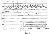
на фиг.1 представлен график, иллюстрирующий потенциал элемента как функцию времени для обычной работы в установившемся режиме топливного элемента по сравнению с работой при пульсирующем токе топливного элемента для двух разных интервалов повторения импульсов;figure 1 is a graph illustrating the potential of an element as a function of time for normal operation in a steady state fuel cell compared to operation with a pulsating current of the fuel cell for two different pulse repetition intervals;
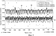
на фиг.2 представлен график, иллюстрирующий мгновенный и усредненный потенциал элемента как функцию времени для обычной работы в установившемся режиме топливного элемента по сравнению с работой при пульсирующем токе;Fig. 2 is a graph illustrating the instantaneous and averaged potential of an element as a function of time for normal operation in a steady state fuel cell compared to operation with a pulsating current;
на фиг.3 представлена условная схема блока питания на основе электрохимических топливных элементов для воплощения алгоритма работы при пульсирующем токе;figure 3 presents a schematic diagram of a power supply based on electrochemical fuel cells for implementing the algorithm of operation with a pulsating current;
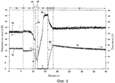
на фиг.4 представлен график, иллюстрирующий напряжение пакета и ток пакета как функцию времени перед импульсом гидратации пакета, во время этого импульса и после него, и4 is a graph illustrating the voltage of the packet and the current of the packet as a function of time before the pulse of hydration of the packet, during this pulse and after it, and
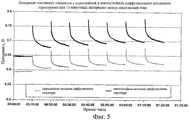
на фиг.5 представлен график, иллюстрирующий сравнительное улучшение рабочей характеристики топливного элемента для работы при пульсирующем токе в (i) топливном элементе с однослойным катодным диффузором и (ii) топливном элементе с многослойным катодным диффузором.5 is a graph illustrating a comparative improvement in the performance of a fuel cell for pulsating current operation in (i) a fuel cell with a single layer cathode diffuser and (ii) a fuel cell with a multilayer cathode diffuser.
В изобретении предложено временное нарушение равновесия (которое может определяться существующими рабочими условиями пакета топливных элементов) содержания воды в мембране и скорости отвода воды для достижения большего кпд пакета и системы. Эта процедура предусматривает образование избыточной воды у катода топливного элемента за короткие периоды времени и последующую эксплуатацию пакета с улучшенной рабочей характеристикой при постепенном восстановлении равновесия с меньшим содержанием воды. При необходимости этот процесс можно повторять с определенными частотами интервалов.The invention proposed a temporary imbalance (which may be determined by the existing operating conditions of the fuel cell package) of the water content in the membrane and the rate of water drainage to achieve greater efficiency of the package and system. This procedure involves the formation of excess water at the cathode of the fuel cell for short periods of time and the subsequent operation of the package with improved performance while gradually restoring equilibrium with a lower water content. If necessary, this process can be repeated with certain interval frequencies.
Короткие периоды времени, в течение которых образуется избыточная вода, называются в этом описании «интервалами регидратации», и этот термин предназначен для указания периода времени, в течение которого блок топливных элементов активно управляет своей рабочей средой, преднамеренно увеличивая уровни гидратации, чтобы сделать их выше уровня, который в противном случае превалировал бы на основе электрической нагрузки, внешней по отношению к топливному элементу, и его окружающих рабочих условий, таких, как температура. Этого процесса регидратации можно достичь одним или обоими нижеследующими методами:Short periods of time during which excess water is formed are referred to in this description as “rehydration intervals”, and this term is intended to indicate the period of time during which the fuel cell unit actively controls its working environment, deliberately increasing hydration levels to make them higher a level that would otherwise prevail based on an electrical load external to the fuel cell and its surrounding operating conditions, such as temperature. This rehydration process can be achieved by one or both of the following methods:
а) эксплуатацией топливного элемента с большей выходной мощностью, чем при «нормальных» рабочих условиях, определяемых прикладываемой нагрузкой, внешней по отношению к блоку топливных элементов, вследствие чего образуется избыточная вода за счет электрохимической реакции, иa) the operation of a fuel cell with a higher output power than under “normal” operating conditions determined by the applied load external to the fuel cell block, resulting in excess water due to an electrochemical reaction, and
б) модуляцией или кратковременной остановкой движения объема (кратковременным прекращением расхода) воздуха через топливный элемент для минимизации процесса отвода воды.b) modulation or short-term stop of the volume movement (short-term stop of flow) of air through the fuel cell to minimize the process of water drainage.
Основным преимуществом этой процедуры является улучшенная рабочая характеристика при нормальных рабочих условиях, получаемая благодаря более высокому напряжению элемента, что дает повышенный кпд преобразования энергии. Это приводит к меньшей рабочей температуре пакета, что может продлить ожидаемый срок службы мембраны. Выгодные эффекты процесса регидратации, описанные здесь, наиболее очевидны во время запуска блока топливных элементов. Это, в частности, случай кондиционирования вновь создаваемого топливного элемента, когда процесс регидратации может улучшить отклик пакета не кондиционированных топливных элементов на немедленные большие нагрузки.The main advantage of this procedure is the improved performance under normal operating conditions, obtained due to the higher voltage of the element, which gives increased energy conversion efficiency. This results in a lower package operating temperature, which can extend the expected membrane life. The beneficial effects of the rehydration process described herein are most apparent during startup of the fuel cell unit. This is, in particular, the case of conditioning a newly created fuel cell, when the rehydration process can improve the response of a package of non-conditioned fuel cells to immediate heavy loads.
Вторым преимуществом является создание пакетов топливных элементов (с открытыми катодами), охлаждаемых воздухом, для работы в широком диапазоне условий окружающей среды, в частности условиях повышенной температуры и пониженной влажности. В системе топливных элементов, в которой используется пакет с открытыми катодами, обычно единственным способом регулирования содержания воды в мембране топливного элемента является изменение воздушного потока, подаваемого охлаждающим вентилятором, при этом увеличение воздушного потока будет приводить к меньшей температуре пакета, и наоборот, меньший поток воздуха будет приводить к нагреву пакета. Вместе с тем, в зависимости от влажности окружающего воздуха, любое из этих воздействий может на самом деле привести к дополнительным потерям воды из пакета. В изобретении предлагается встраивание пакета топливных элементов в систему с аппаратными средствами и операционным контроллером для обеспечения регидратации, не зависящей непосредственно от рабочих условий окружающей среды и внешней нагрузки, с целью поддержания более оптимальной рабочей характеристики.The second advantage is the creation of air-cooled fuel cell packages (with open cathodes) for operation in a wide range of environmental conditions, in particular, conditions of elevated temperature and low humidity. In a fuel cell system that uses an open cathode bag, usually the only way to control the water content in the membrane of the fuel cell is to change the air flow supplied by the cooling fan, while increasing the air flow will result in a lower temperature of the bag, and vice versa, less air flow will heat up the bag. However, depending on the humidity of the surrounding air, any of these effects can actually lead to additional losses of water from the bag. The invention proposes the integration of a fuel cell package into a system with hardware and an operational controller to provide rehydration independent of the environmental and external load conditions in order to maintain a more optimal performance.
На фиг.1 показано влияние периодического и временного увеличения тока, снимаемого с топливного элемента, выше его базовой нагрузки, до большего тока. В данном случае пакет работал при базовой нагрузке 320 мА/см2. Эту базовую нагрузку можно рассматривать как такую, которая определяется потреблением тока, внешним по отношению к блоку топливных элементов, вместе с непрерывной паразитной нагрузкой на пакет топливных элементов, обуславливаемой самим пакетом топливных элементов (т.е. схемами управления, вентиляторами и т.д.). Периодическое и временно увеличенное потребление тока в пакете топливных элементов происходило в виде импульсов тока, в которых ток пакета увеличивался до 900 мА/см2 за интервал регидратации приблизительно 5 секунд через интервалы величиной две и пять минут соответственно. Общее повышение кпд было основано на низшей теплотворной способности (НТС) Н2 при 50 градусах Цельсия и предполагает нулевой кпд в течение 5-секундного импульса регидратации при большой нагрузке.Figure 1 shows the effect of a periodic and temporary increase in the current taken from the fuel cell, above its base load, to a larger current. In this case, the package worked at a base load of 320 mA / cm 2 . This basic load can be considered as such, which is determined by the current consumption external to the fuel cell block, together with the continuous stray load on the fuel cell stack caused by the fuel cell stack itself (i.e., control circuits, fans, etc. ) Periodic and temporarily increased current consumption in the fuel cell stack occurred as current pulses in which the stack current increased to 900 mA / cm 2 over a rehydration interval of approximately 5 seconds at intervals of two and five minutes, respectively. The overall increase in efficiency was based on the lower calorific value (NTS) of N 2 at 50 degrees Celsius and assumed zero efficiency for a 5-second rehydration pulse under heavy load.
Базовая нагрузка 320 мА/см2 в установившемся режиме приводит к напряжению элемента чуть выше 0,65 В, как показано линией 10 на фиг.1, и НТС 52,4%. Напряжение элемента при работе с интервалами регидратации 5 секунд, наступающими через каждые 2 минуты, задается линией 11 на фиг.1. Это соответствует рабочему циклу регидратации примерно 4,2% и дает НТС на уровне 57,6%. Напряжение на элементе при работе с интервалами регидратации 5 секунд, наступающими через каждые 5 минут, задается линией 12 на фиг.1. Это соответствует рабочему циклу регидратации примерно 1,7% и дает НТС на уровне 57,2%.The base load of 320 mA / cm 2 in steady state leads to an element voltage slightly higher than 0.65 V, as shown by
На фиг.1 ясно видно непосредственное увеличение напряжения элемента после интервалов гидратации, и последующий спад. Улучшение рабочей характеристики будет зависеть от коэффициентов удержания воды для топливного элемента, в частности, характеристик полимерной мембраны и любых газодиффузионных слоев, содержащихся в ней, а также температуры пакета элементов и воздушного потока через него. Интервалы гидратации особенно эффективны при использовании совместно с усовершенствованными диффузионными средами, примыкающими к МЭБ, способствующими управлению уровнями воды в мембране и поддержанию этих уровней. Следовательно, это изобретение особенно выгодно, когда его используют совместно с многослойными диффузионными структурами, которые способствуют улавливанию воды, как в случае компоновки пакетов с открытыми катодами, описанной в патентной заявке 0501598.7 Соединенного Королевства и в соответствующей международной патентной заявке PCT/GB2006/000074. На фиг.5 показано сравнение между улучшениями в рабочей характеристике топливного элемента, наблюдаемыми при работе с пульсирующим током в (i) топливном элементе с однослойным катодным диффузором и (ii) топливном элементе с многослойным катодным диффузором. Верхний график демонстрирует напряжение элемента для конфигурации (ii), а нижний график демонстрирует напряжение элемента для конфигурации (i). Импульсы регидратации появляются через каждые десять минут.Figure 1 clearly shows a direct increase in the voltage of the element after intervals of hydration, and the subsequent decline. Improving the performance will depend on the water retention factors for the fuel cell, in particular, the characteristics of the polymer membrane and any gas diffusion layers contained therein, as well as the temperature of the cell stack and air flow through it. Hydration intervals are especially effective when used in conjunction with advanced diffusion media adjacent to the OIE, helping to control and maintain water levels in the membrane. Therefore, this invention is particularly advantageous when used in conjunction with multilayer diffusion structures that facilitate the capture of water, as in the case of open cathode bags described in United Kingdom Patent Application 0501598.7 and corresponding international patent application PCT / GB2006 / 000074. Figure 5 shows a comparison between improvements in the fuel cell performance observed with pulsating current in (i) a single-layer cathode diffuser fuel cell and (ii) a multi-layer cathode diffuser fuel cell. The upper graph shows the cell voltage for configuration (ii), and the lower graph shows the cell voltage for configuration (i). Rehydration pulses appear every ten minutes.
Фиг.2 иллюстрирует эффект в реальном времени и усредненное напряжение элемента характерно для топливного элемента при наличии и отсутствии импульсов тока для регидратации. Ось напряжения элемента отображает среднее напряжение элемента по всему пакету, т.е. напряжение пакета, деленное на количество элементов в пакете. Верхняя прямая линия 20 иллюстрирует усредненное по времени напряжение элемента чуть выше 0,69 В, а верхний график 21 иллюстрирует мгновенное напряжение элемента, причем и упомянутая линия, и упомянутый график соответствуют режиму, в котором пакет работает с интервалами регидратации. Нижняя прямая линия 22 иллюстрирует усредненное по времени напряжение элемента чуть выше 0,65 В, а нижний график 23 иллюстрирует мгновенное напряжение элемента, причем и упомянутая линия, и упомянутый график соответствуют режиму, в котором пакет работает без интервалов регидратации. Следует отметить, что нижний график 23 демонстрирует ту же периодичность на частоте, отличающейся от частоты верхнего графика 21, потому что в обоих случаях происходит периодическая продувка анодов для очистки от воды, накапливающейся на анодной конфигурации, которая в остальное время является конфигурацией анодов с замкнутыми концами, и это является доминирующим фактором на нижнем графике 23. Анод с замкнутыми концами периодически переключается с переходом к конфигурации с разомкнутыми концами, чтобы сдуть воду с анода в течение примерно 1 секунды. Вместе с тем влияния интервалов регидратации совершенно очевидны из значительного увеличения среднего и мгновенного напряжений 20, 21 по сравнению с эквивалентными напряжениями 22, 23, полученными без интервалов регидратации.Figure 2 illustrates the effect in real time and the average cell voltage is characteristic of a fuel cell in the presence and absence of current pulses for rehydration. The voltage axis of the element displays the average voltage of the element over the entire package, i.e. packet voltage divided by the number of elements in the packet. The upper
Для использования влияния интервалов регидратации на систему топливных элементов требуется дополнительная система управления, описываемая в связи с фиг.3.To use the effect of rehydration intervals on the fuel cell system, an additional control system is required, described in connection with FIG.
Блок 30 электрохимических топливных элементов содержит пакет 31 топливных элементов, имеющий некоторое количество топливных элементов 32, соединенных последовательно. Каждый топливный элемент 32 включает в себя мембранно-электродный блок и пластины потока текучей среды, для подачи в них топлива и окислителя в соответствии с обычной конструкцией пакета топливных элементов. Электрический выход 33 обеспечивает вывод электрического тока из пакета 31. Охлаждающая система 34 такая, как вентилятор, обеспечивает охлаждение и воздушного потока, и кислорода, подаваемого в пластины потока текучей среды. Мощность из блока 30 топливных элементов подается на внешнюю нагрузку 41 посредством внешних выходных клемм 35 питания через реле 42 и 43.The electrochemical
Внутренняя электрическая нагрузка 36 переключается переключателем 37 под управлением контроллера 38 мощности для периодического и временного увеличения тока, снимаемого с пакета 31 топливных элементов. С выходными клеммами 35 через реле 43 соединен вспомогательный или «резервный» источник 39 питания для подачи мощности на выходные клеммы 35 питания в моменты, когда пакет 31 топливных элементов переключен на питание внутренней нагрузки 36. Схемой 40 управления нагрузкой и охлаждающей системой 34 также может управлять контроллер 38 мощности. Резервный источник 39 питания предпочтительно представляет собой аккумуляторную батарею, но можно использовать и любую другую форму подходящего устройства накопления зарядов такую, как суперконденсаторы. Схема 40 управления нагрузкой предпочтительно представляет собой преобразователь постоянного тока в постоянный ток.The internal electrical load 36 is switched by a switch 37 under the control of the power controller 38 to periodically and temporarily increase the current taken from the fuel cell stack 31. An auxiliary or “standby” power source 39 is connected to the
При эксплуатации пакет 31 топливных элементов обычно переключен на питание внешней нагрузки 41, тогда как и внутренняя нагрузка 36, и резервный источник 39 питания электрически изолированы от пакета 31 топливных элементов и выходных клемм 35 питания.In operation, the fuel cell stack 31 is typically switched to power the external load 41, while both the internal load 36 and the backup power supply 39 are electrically isolated from the fuel cell stack 31 and the
Вместе с тем в течение интервалов регидратации контроллер 38 мощности открывает реле 42 и задействует переключатель 37 таким образом, что резервный источник 39 питания изолируется от пакета 31 топливных элементов, а ток из пакета 31 топливных элементов отводится на внутреннюю нагрузку 36. Чтобы при этом избежать прерывания подачи мощности на внешнюю нагрузку 41, контроллер 38 мощности поддерживает реле 43 в замкнутом состоянии для поддержания электрической целостности между резервным источником 39 питания и выходными клеммами 35 питания и тем самым - подачи мощности на внешнюю нагрузку 41. В конце интервала регидратации контроллер 39 задействует переключатель 37 и реле 42 для изоляции внутренней нагрузки 36 от пакета 31 топливных элементов и восстановления соединения пакета топливных элементов с выходными клеммами 41. В этот момент резервный источник 39 питания предпочтительно остается соединенным таким образом, что его можно перезаряжать током из пакета 31 топливных элементов. После надлежащего периода зарядки схема 40 управления нагрузкой может срабатывать, изолируя резервный источник 39 питания с помощью третьего реле 44. В альтернативном варианте резервный источник 39 питания можно просто оставлять всегда подсоединенным.However, during the rehydration intervals, the power controller 38 opens the relay 42 and activates the switch 37 so that the backup power source 39 is isolated from the fuel cell stack 31 and the current from the fuel cell stack 31 is diverted to the internal load 36. In order to avoid interruption supplying power to the external load 41, the power controller 38 keeps the relay 43 closed to maintain electrical integrity between the backup power source 39 and the
Таким образом, будет ясно, что пакет 31 топливных элементов является основным источником питания, а в течение интервала регидратации батарея 39 является единственным поставщиком мощности к внешней нагрузке 41. Когда пакет 31 топливных элементов снова оказывается подключенным, он способен полностью перезарядить батарею 39, а когда эта батарея становится полностью заряженной, подача тока в нее будет прекращена.Thus, it will be clear that the fuel cell stack 31 is the main power source, and during the rehydration interval, the battery 39 is the only power supplier to the external load 41. When the fuel cell stack 31 is reconnected, it is able to fully recharge the battery 39, and when this battery becomes fully charged, the current supply to it will be stopped.
В эту компоновку можно внести различные изменения. Например, переключатель 37 не обязательно должен быть из семейства двухпозиционных переключателей, если не требуется изолировать пакет 31 топливных элементов и внутреннюю нагрузку 36 от внешней нагрузки 41 в течение интервала гидратации. Иными словами, если можно будет по-прежнему подавать требуемую мощность на внешнюю нагрузку 41 в течение интервала регидратации, то, в принципе, внутреннюю нагрузку 36 можно просто прибавлять к внешней нагрузке 41, по схеме параллельного соединения, в течение интервала регидратации. В этом случае резервный источник 39 питания может и не потребоваться, поскольку поддерживается протекание тока от пакета 31 топливных элементов к внешней нагрузке 41 даже в течение интервала регидратации. Аналогичным образом выходные клеммы 35 питания могут быть непосредственно соединены с пакетом 31 топливных элементов, внутренняя нагрузка 36, при необходимости, может быть выполнена подключаемой и отключаемой в первой параллельной схеме, а резервный источник 39 питания, при необходимости, может быть выполнен подключаемым и отключаемым с возможностью управления зарядкой во второй параллельной схеме.You can make various changes to this layout. For example, the switch 37 does not have to be from the family of on / off switches if it is not necessary to isolate the fuel cell stack 31 and the internal load 36 from the external load 41 during the hydration interval. In other words, if it is still possible to supply the required power to the external load 41 during the rehydration interval, then, in principle, the internal load 36 can simply be added to the external load 41, according to the parallel connection scheme, during the rehydration interval. In this case, a redundant power supply 39 may not be necessary, since current flows from the fuel cell stack 31 to the external load 41, even during the rehydration interval. Similarly, the
Таким образом, вообще говоря, следует признать, что контроллер 38 управления мощностью пакета может использовать внутреннюю нагрузку 36 для периодического и временного увеличения тока, снимаемого с пакета топливных элементов, помимо или вместо независимого потребления тока, которое является внешним по отношению к блоку топливных элементов, в течение интервалов регидратации. Если потребуется, то можно использовать устройство управления мощностью для переключения внутренней нагрузки 36 на управляемой основе во избежание значительных переходных процессов при переключениях.Thus, generally speaking, it should be recognized that the packet power control controller 38 can use the internal load 36 to periodically and temporarily increase the current taken from the fuel cell stack, in addition to or instead of independently consuming current that is external to the fuel cell stack, during rehydration intervals. If necessary, you can use the power control device to switch the internal load 36 on a controlled basis to avoid significant transients during switching.
Интервалы регидратации также можно воплощать с помощью периодического временного уменьшения воздушного потока к катодам пакета 31 топливных элементов. Таким образом, контроллеру 38 мощности можно придать конфигурацию, обеспечивающую уменьшение питания охлаждающего вентилятора 34 в течение интервала регидратации. В предпочтительном варианте охлаждающий вентилятор отключают в течение интервала регидратации.Rehydration intervals can also be implemented by periodically temporarily reducing the air flow to the cathodes of the fuel cell stack 31. Thus, the power controller 38 can be configured to reduce the power of the cooling fan 34 during the rehydration interval. In a preferred embodiment, the cooling fan is turned off during the rehydration interval.
Таким образом, вообще говоря, контроллер 38 мощности пакета может модулировать воздушный поток через пакет 31 топливных элементов на периодической основе независимо от потребления электрического тока в пакете топливных элементов, для обеспечения интервалов регидратации, которые увеличивают уровень гидратации топливных элементов. Слово «независимо» в этом контексте предназначено для указания на независимость блок 30 топливных элементов от немедленных или переходных изменений во внешней электрической нагрузке 41.Thus, generally speaking, the packet power controller 38 can modulate the air flow through the fuel cell stack 31 on a periodic basis, regardless of the electric current consumption in the fuel cell stack, to provide rehydration intervals that increase the hydration level of the fuel cells. The word "independently" in this context is intended to indicate the independence of the
В целях воплощения интервалов регидратации можно использовать и модуляцию воздуха, и увеличенную нагрузку. График согласно фиг.4 иллюстрирует профили тока и напряжения для этой операции. Верхний график 50 отображает напряжение пакета как функцию времени, а нижний график 51 отображает ток пакета как функцию времени.In order to implement rehydration intervals, both air modulation and increased load can be used. The graph of FIG. 4 illustrates current and voltage profiles for this operation. The
В течение временного периода 52 (t=0-6 секунд) показана нормальная работа топливного элемента. В течение следующего временного периода 53 (t=0-10 секунд) охлаждающие вентиляторы 34, обеспечивающие воздушный поток к катоду, отключены, что вызывает рост температуры пакета. К концу этого периода времени наблюдается небольшое уменьшение напряжения элементов с соответствующим небольшим ростом тока для поддержания постоянной мощности вследствие ограничений по массопереносу. В момент, когда напряжение, подаваемое на преобразователь 40 постоянного тока в постоянный ток, достигает величины напряжения клемм батареи 39, ток из топливного элемента уменьшается до нуля. В данном случае подача мощности на выходные клеммы 35 будет пополняться батареей 39.During the time period 52 (t = 0-6 seconds), the normal operation of the fuel cell is shown. During the next time period 53 (t = 0-10 seconds), the cooling fans 34 providing air flow to the cathode are turned off, which causes the temperature of the stack to rise. Towards the end of this time period, a slight decrease in the voltage of the elements with a corresponding small increase in current is observed to maintain a constant power due to restrictions on mass transfer. At the moment when the voltage supplied to the DC /
Затем выход из пакета 31 топливных элементов изолируется размыканием реле 42 при минимальной электронной нагрузке, оставляя батарею 39 обеспечивающей непрерывную подачу мощности в приложение (например, на внешнюю нагрузку 41), реализуемую падением тока до нуля в период времени 54 (t~10-11 секунд). В момент t=11 секунд внутренний нагрузочный резистор 36 подключается к клеммам 33 пакета 31 топливных элементов, о чем свидетельствует всплеск 55. Это приводит к дополнительному электрическому нагружению пакета 31 топливных элементов в течение управляемого периода времени, а именно интервала 56 большого тока (t~11-12 секунд).Then, the output from the fuel cell stack 31 is isolated by opening the relay 42 at the minimum electronic load, leaving the battery 39 providing a continuous supply of power to the application (for example, to the external load 41), which is realized by dropping the current to zero during a period of 54 (t ~ 10-11 seconds ) At time t = 11 seconds, the internal load resistor 36 is connected to the terminals 33 of the fuel cell stack 31, as indicated by
В течение этого интервала 56 большого тока происходит потребление окислителя, остающегося внутри проточных каналов текучей среды пакета 31 топливных элементов, а напряжение на клеммах пакета снижается до 0 В. При отсутствии вентиляторов 34, отсасывающих побочный продукт в виде воды, на границе раздела МЭБ и газодиффузионного слоя каждого элемента 32 остается избыточная вода. По истечении интервала 56 большого тока пакет 31 топливных элементов оказывается изолированным от всей электрической нагрузки в течение интервала 57 изоляции электрической нагрузки (t=12-16 секунд). В течение этого интервала изоляции протекание тока является нулевым, а напряжение 50 пакета возвращается к пику в момент 58 (t=16 секунд). В течение интервала 59 времени повторного соединения (t~6-18 секунд) мощность из пакета 31 снова задействуется управляемым образом с помощью цифрового управления и подается в преобразователь 40 постоянного тока в постоянный ток для постепенного увеличения уставки предела тока. В момент 60 топливный элемент полностью задействован и начинает перезаряжать батарею 39 (в момент t=18 секунд). Топливный элемент перезаряжает батарею, а также подает мощность на внешнюю нагрузку 41 в течение следующего периода 61 времени. Ток постепенно падает по мере приближения батареи 39 к состоянию полной зарядки.During this high
По истечении подходящего интервала времени, например от 2 до 5 минут, инициируется следующая операция регидратации (не показанная на фиг.4). Можно использовать любой подходящий интервал времени, который эффективен для обеспечения полезного среднего увеличения напряжения элемента. В зависимости от условий окружающей среды таких, как температура и влажность, и от того, работает ли топливный элемент под постоянной фиксированной или переменной нагрузкой, интервал времени может быть коротким, составляя 1 минуту, или длинным, составляя, например, 2 часа.After a suitable time interval, for example from 2 to 5 minutes, the next rehydration operation (not shown in FIG. 4) is initiated. Any suitable time interval that is effective to provide a useful average increase in cell voltage can be used. Depending on the environmental conditions, such as temperature and humidity, and whether the fuel cell operates under constant fixed or variable load, the time interval can be short, amounting to 1 minute, or long, for example, 2 hours.
Оптимальная частота операции регидратации может зависеть от ряда факторов, включая атмосферные условия, такие, как температура и влажность. Когда используется многослойный катодный газодиффузионный слой, то оказываются возможными значительно большее повышение электрохимической рабочей характеристики и более длительный период времени возврата рабочей характеристики топливного элемента к равновесному уровню по сравнению с компоновками, предусматривающими единственный газодиффузионный слой. Это также случай использования метода, предусматривающего применение пакетов с открытыми катодами в противоположность обычным герметизированным катодам, причем в последнем случае принудительное направление воздушного потока по каналам приводит к быстрому отводу избыточной воды.The optimal frequency of rehydration operations may depend on a number of factors, including atmospheric conditions, such as temperature and humidity. When a multilayer cathode gas diffusion layer is used, it is possible to significantly increase the electrochemical performance and a longer period of time to return the fuel cell performance to an equilibrium level compared to arrangements involving a single gas diffusion layer. This is also the case of using a method involving the use of open-cathode bags as opposed to conventional sealed cathodes, in which case the forced air flow through the channels leads to the rapid removal of excess water.
Операции регидратации предпочтительно выполняются автоматически на основе фиксированной периодичности. Вместе с тем следует понять, что можно использовать и дополнительный алгоритм управления для переключения блока 30 топливных элементов между нормальным режимом, в котором операции регидратации не проводятся, и режимом с регидратацией, в котором проводятся периодические и временные операции регидратации. Периодичностью операций регидратации можно управлять в соответствии с некоторым измеряемым параметром пакета, таким, как средняя температура, влажность, профиль напряжения, профиль тока и потребление мощности, и т.д. Рабочим циклом интервалов регидратации можно управлять в соответствии с некоторыми измеряемыми параметрами пакета, такими, как средняя температура, влажность, профиль напряжения, профиль тока и потребление мощности, и т.д. В предпочтительном варианте в течение интервала 57 изоляции происходит съем нулевого тока, но должно быть ясно, что возможен и съем малого тока. В некоторых вариантах осуществления интервал изоляции может и не потребоваться.Rehydration operations are preferably performed automatically based on a fixed periodicity. However, it should be understood that an additional control algorithm can be used to switch the
Другие варианты осуществления следует считать находящимися в рамках объема притязаний прилагаемой формулы изобретения.Other embodiments should be deemed to be within the scope of the appended claims.
Claims (15)
контроллер мощности пакета, содержащий переключаемое нагрузочное устройство и выполненный с возможностью периодического и временного увеличения тока, снимаемого с пакета топливных элементов, в дополнение или вместо независимого потребления тока, которое является внешним по отношению к упомянутому блоку топливных элементов, путем пропускания тока из пакета топливных элементов через переключаемое нагрузочное устройство в течение интервалов регидратации для увеличения уровня гидратации топливных элементов.1. An electrochemical fuel cell unit comprising a fuel cell stack comprising a plurality of fuel cells, each of which includes a membrane electrode assembly and fluid flow plates for supplying fuel and an oxidizing agent thereto, and an electrical outlet for outputting current from the stack, and
a package power controller comprising a switchable load device and configured to periodically and temporarily increase the current taken from the fuel cell stack in addition to or instead of independently consuming current that is external to said fuel cell stack by passing current from the fuel cell stack through a switchable load device during rehydration intervals to increase the hydration level of the fuel cells.
средства поддержания потребления тока нагрузкой, внешней по отношению к блоку топливных элементов, в течение интервалов регидратации.11. An electrochemical fuel cell unit comprising a fuel cell stack comprising a plurality of fuel cells, each of which includes a membrane electrode assembly and fluid flow plates for supplying fuel and an oxidizing agent thereto, and an electrical outlet for outputting current from the stack, a packet controller configured to modulate the air flow through the fuel cell stack on a periodic basis regardless of current consumption in the fuel cell stack unit to provide rehydration intervals tation, which increase the hydration level of the fuel cell, and
means for maintaining current consumption by a load external to the fuel cell block during rehydration intervals.
модулируют воздушный поток через пакет топливных элементов на периодической основе независимо от потребления тока в блоке с пакетом топливных элементов, для обеспечения интервалов регидратации, увеличивающих уровень гидратации топливных элементов, и одновременно поддерживают потребление тока нагрузкой, внешней по отношению к блоку топливных элементов, в течение интервалов регидратации.14. A method of operating an electrochemical fuel cell unit with a fuel cell stack containing a plurality of fuel cells, each of which includes a membrane electrode assembly and fluid flow plates for supplying fuel and an oxidizing agent thereto, and an electrical output for outputting current from the stack , the method includes the steps at which
modulate the air flow through the fuel cell stack on a periodic basis, regardless of the current consumption in the block with the fuel cell stack, to provide rehydration intervals that increase the hydration level of the fuel cells, and at the same time maintain the current consumption by the load external to the fuel cell block for intervals rehydration.
Applications Claiming Priority (2)
| Application Number | Priority Date | Filing Date | Title |
|---|---|---|---|
| GB0604241A GB2435711B (en) | 2006-03-03 | 2006-03-03 | Rehydration of fuel cells |
| GB0604241.0 | 2006-03-03 |
Publications (2)
| Publication Number | Publication Date |
|---|---|
| RU2008139284A RU2008139284A (en) | 2010-04-10 |
| RU2417486C2 true RU2417486C2 (en) | 2011-04-27 |
Family
ID=36219027
Family Applications (1)
| Application Number | Title | Priority Date | Filing Date |
|---|---|---|---|
| RU2008139284/07A RU2417486C2 (en) | 2006-03-03 | 2007-03-05 | Rehydration of fuel elements |
Country Status (18)
| Country | Link |
|---|---|
| US (1) | US8263277B2 (en) |
| EP (2) | EP1992037B1 (en) |
| JP (1) | JP5580991B2 (en) |
| KR (1) | KR101486902B1 (en) |
| CN (1) | CN101411022B (en) |
| AR (2) | AR059744A1 (en) |
| AT (1) | ATE487245T1 (en) |
| BR (1) | BRPI0708440A2 (en) |
| CA (2) | CA2826749C (en) |
| DE (1) | DE602007010248D1 (en) |
| ES (2) | ES2397784T3 (en) |
| GB (1) | GB2435711B (en) |
| MX (1) | MX2008011288A (en) |
| NO (1) | NO20083625L (en) |
| RU (1) | RU2417486C2 (en) |
| TW (1) | TWI401837B (en) |
| WO (1) | WO2007099360A2 (en) |
| ZA (1) | ZA200807462B (en) |
Families Citing this family (10)
| Publication number | Priority date | Publication date | Assignee | Title |
|---|---|---|---|---|
| JP5545378B2 (en) * | 2011-02-16 | 2014-07-09 | トヨタ自動車株式会社 | Fuel cell system and vehicle equipped with the same |
| GB2513636A (en) * | 2013-05-02 | 2014-11-05 | Intelligent Energy Ltd | A fuel cell system |
| JP6341123B2 (en) * | 2015-03-16 | 2018-06-13 | スズキ株式会社 | Fuel cell humidifier and fuel cell motorcycle |
| GB2543031A (en) * | 2015-09-29 | 2017-04-12 | Intelligent Energy Ltd | Fuel cell system controller and associated method |
| CN105720283A (en) * | 2016-04-07 | 2016-06-29 | 北京建筑大学 | Fuel cell hybrid power system and working method thereof |
| US10998562B2 (en) | 2016-04-14 | 2021-05-04 | Intelligent Energy Limited | PEM fuel cell power systems with efficient hydrogen generation |
| WO2018046990A1 (en) | 2016-09-07 | 2018-03-15 | Intelligent Energy Limited | Ground stations and methods for pem fuel cell powered unmanned aerial vehicles |
| WO2019050959A1 (en) | 2017-09-05 | 2019-03-14 | Intelligent Energy Inc. | Compact efficient hydrogen reactor |
| DE102022211779A1 (en) | 2022-11-08 | 2024-05-08 | Robert Bosch Gesellschaft mit beschränkter Haftung | Method for operating a fuel cell system |
| DE102023201054A1 (en) | 2023-02-09 | 2024-08-14 | Robert Bosch Gesellschaft mit beschränkter Haftung | Fuel cell system and operating method for a fuel cell system in high pressure operation |
Family Cites Families (19)
| Publication number | Priority date | Publication date | Assignee | Title |
|---|---|---|---|---|
| US3432356A (en) * | 1963-09-11 | 1969-03-11 | Gen Electric | Regulated fuel cell system |
| JP2001513940A (en) * | 1998-03-06 | 2001-09-04 | マグネート−モートア、ゲゼルシャフト、フュール、マグネートモートリシェ、テヒニク、ミット、ベシュレンクテル、ハフツング | Gas diffusion electrode and polymer electrolyte membrane fuel cell with low water diffusion capacity |
| US6214487B1 (en) * | 1999-02-01 | 2001-04-10 | Motorola, Inc. | Integral sensors for monitoring a fuel cell membrane and methods of monitoring |
| WO2001028022A1 (en) * | 1999-10-14 | 2001-04-19 | Motorola Inc. | Method and apparatus for managing hydration level of fuel cell electrolyte |
| US6589682B1 (en) * | 2000-01-27 | 2003-07-08 | Karen Fleckner | Fuel cells incorporating nanotubes in fuel feed |
| JP2001229943A (en) * | 2000-02-14 | 2001-08-24 | Nissan Motor Co Ltd | Fuel cell system |
| US6835481B2 (en) * | 2000-03-29 | 2004-12-28 | Idatech, Llc | Fuel cell system with load management |
| US20030003341A1 (en) * | 2001-06-29 | 2003-01-02 | Kinkelaar Mark R. | Liquid fuel cell reservoir for water and/or fuel management |
| GB2412784B (en) * | 2002-01-18 | 2006-08-23 | Intelligent Energy Ltd | Fuel cell oxygen removal and pre-conditioning system |
| JP4193521B2 (en) * | 2002-03-20 | 2008-12-10 | ソニー株式会社 | FUEL CELL DEVICE AND FUEL CELL CONTROL METHOD |
| TW558852B (en) * | 2002-07-12 | 2003-10-21 | Asia Pacific Fuel Cell Tech | Control apparatus and method of fuel cell set |
| TW550851B (en) * | 2002-07-17 | 2003-09-01 | Asia Pacific Fuel Cell Tech | Fuel battery having moisturizing module |
| US7318971B2 (en) * | 2003-02-14 | 2008-01-15 | Denso Corporation | Fuel cell system utilizing control of operating current to adjust moisture content within fuel cell |
| JP4608892B2 (en) * | 2003-02-14 | 2011-01-12 | 株式会社デンソー | Fuel cell system |
| JP2005085532A (en) * | 2003-09-05 | 2005-03-31 | Nissan Motor Co Ltd | Fuel cell system |
| US7297428B2 (en) * | 2003-10-31 | 2007-11-20 | 3M Innovative Properties Company | Registration arrangement for fuel cell assemblies |
| US7270900B2 (en) | 2003-11-03 | 2007-09-18 | Mti Microfuel Cells, Inc. | Automatic measurement of fuel cell resistance |
| JP2006079955A (en) * | 2004-09-10 | 2006-03-23 | Casio Comput Co Ltd | Fuel cell system, and container for power generating fuel |
| US7754361B2 (en) * | 2007-05-30 | 2010-07-13 | Idatech, Llc | Fuel cell systems with maintenance hydration by displacement of primary power |
-
2006
- 2006-03-03 GB GB0604241A patent/GB2435711B/en not_active Expired - Fee Related
-
2007
- 2007-03-02 TW TW096107160A patent/TWI401837B/en active
- 2007-03-05 AR ARP070100906A patent/AR059744A1/en active IP Right Grant
- 2007-03-05 ES ES09014297T patent/ES2397784T3/en active Active
- 2007-03-05 CA CA2826749A patent/CA2826749C/en not_active Expired - Fee Related
- 2007-03-05 EP EP07731980A patent/EP1992037B1/en active Active
- 2007-03-05 ES ES07731980T patent/ES2370126T3/en active Active
- 2007-03-05 AT AT07731980T patent/ATE487245T1/en not_active IP Right Cessation
- 2007-03-05 EP EP09014297A patent/EP2161773B1/en active Active
- 2007-03-05 BR BRPI0708440-4A patent/BRPI0708440A2/en not_active Application Discontinuation
- 2007-03-05 CN CN2007800076761A patent/CN101411022B/en active Active
- 2007-03-05 MX MX2008011288A patent/MX2008011288A/en active IP Right Grant
- 2007-03-05 DE DE602007010248T patent/DE602007010248D1/en active Active
- 2007-03-05 KR KR1020087024088A patent/KR101486902B1/en active IP Right Grant
- 2007-03-05 CA CA2644342A patent/CA2644342C/en active Active
- 2007-03-05 WO PCT/GB2007/000760 patent/WO2007099360A2/en active Application Filing
- 2007-03-05 RU RU2008139284/07A patent/RU2417486C2/en not_active IP Right Cessation
- 2007-03-05 JP JP2008556856A patent/JP5580991B2/en active Active
- 2007-03-05 US US12/224,695 patent/US8263277B2/en active Active
-
2008
- 2008-08-22 NO NO20083625A patent/NO20083625L/en not_active Application Discontinuation
- 2008-08-29 ZA ZA200807462A patent/ZA200807462B/en unknown
-
2013
- 2013-03-05 AR ARP130100724A patent/AR090255A2/en not_active Application Discontinuation
Also Published As
Similar Documents
| Publication | Publication Date | Title |
|---|---|---|
| RU2417486C2 (en) | Rehydration of fuel elements | |
| US20080160370A1 (en) | Adaptive Current Controller for a Fuel-Cell System | |
| KR101285997B1 (en) | Fuel cell system operation method and fuel cell system | |
| CN104836319A (en) | Integrated fuel cell power supply system | |
| CN101488580B (en) | System and method for short circuit of fuel cell stack | |
| JP2011103300A (en) | Method for operating fuel cell/battery passive type hybrid power supply | |
| EP1769552A2 (en) | Fuel cell system | |
| JP2007059120A (en) | Fuel battery system | |
| CN204992738U (en) | Integration fuel cell power supply system | |
| CN114024005B (en) | Fuel cell system with rapid shutdown function and shutdown control method | |
| KR20070025834A (en) | Hybrid power supply system of fuel cell and battery with linear voltage profile and operating method | |
| RU70051U1 (en) | FUEL CELL BATTERY FOR A STAND-ALONE POWER SUPPLY | |
| CN216213577U (en) | Standby power generation system of fuel cell of hydrogen station | |
| KR101572033B1 (en) | Apparatus for activating of fuel cell stack | |
| KR20090039441A (en) | Fuel cell system and starting method thereof | |
| PL238623B1 (en) | System for recovering electricity generated during self-humidification of a PEMFC fuel cell stack | |
| KR20130088986A (en) | Power apparatus using cell | |
| CN116455088A (en) | Energy storage system and control method thereof | |
| KR20080044429A (en) | Fuel cell system and emergency driving method | |
| Lee et al. | A Fuel-Cell-Battery Hybrid Platform for Portable Embedded Systems | |
| JP2015204156A (en) | Fuel battery system and control method for the same | |
| JP2013200990A (en) | Fuel cell device |
Legal Events
| Date | Code | Title | Description |
|---|---|---|---|
| MM4A | The patent is invalid due to non-payment of fees |
Effective date: 20160306 |