JP5580991B2 - Humidification of fuel cells - Google Patents
Humidification of fuel cells Download PDFInfo
- Publication number
- JP5580991B2 JP5580991B2 JP2008556856A JP2008556856A JP5580991B2 JP 5580991 B2 JP5580991 B2 JP 5580991B2 JP 2008556856 A JP2008556856 A JP 2008556856A JP 2008556856 A JP2008556856 A JP 2008556856A JP 5580991 B2 JP5580991 B2 JP 5580991B2
- Authority
- JP
- Japan
- Prior art keywords
- fuel cell
- stack
- time
- cell stack
- current
- Prior art date
- Legal status (The legal status is an assumption and is not a legal conclusion. Google has not performed a legal analysis and makes no representation as to the accuracy of the status listed.)
- Active
Links
- 239000000446 fuel Substances 0.000 title claims description 243
- 238000000034 method Methods 0.000 claims description 29
- 239000012528 membrane Substances 0.000 claims description 28
- 239000007800 oxidant agent Substances 0.000 claims description 20
- 230000001590 oxidative effect Effects 0.000 claims description 20
- 239000012530 fluid Substances 0.000 claims description 16
- 230000014759 maintenance of location Effects 0.000 claims description 11
- 238000009413 insulation Methods 0.000 claims description 10
- 238000012423 maintenance Methods 0.000 claims description 2
- 230000003020 moisturizing effect Effects 0.000 claims description 2
- XLYOFNOQVPJJNP-UHFFFAOYSA-N water Substances O XLYOFNOQVPJJNP-UHFFFAOYSA-N 0.000 description 21
- 238000009792 diffusion process Methods 0.000 description 18
- 239000010410 layer Substances 0.000 description 11
- 238000001816 cooling Methods 0.000 description 10
- 230000008569 process Effects 0.000 description 9
- 239000007789 gas Substances 0.000 description 7
- UFHFLCQGNIYNRP-UHFFFAOYSA-N Hydrogen Chemical compound [H][H] UFHFLCQGNIYNRP-UHFFFAOYSA-N 0.000 description 5
- 230000007423 decrease Effects 0.000 description 5
- 238000013459 approach Methods 0.000 description 4
- 230000008859 change Effects 0.000 description 4
- 238000006243 chemical reaction Methods 0.000 description 4
- 230000000694 effects Effects 0.000 description 4
- 230000006872 improvement Effects 0.000 description 4
- 206010016807 Fluid retention Diseases 0.000 description 2
- 230000008901 benefit Effects 0.000 description 2
- 230000003247 decreasing effect Effects 0.000 description 2
- 238000013461 design Methods 0.000 description 2
- 238000003487 electrochemical reaction Methods 0.000 description 2
- 238000010438 heat treatment Methods 0.000 description 2
- 238000002955 isolation Methods 0.000 description 2
- 230000002045 lasting effect Effects 0.000 description 2
- 230000003071 parasitic effect Effects 0.000 description 2
- 229920005597 polymer membrane Polymers 0.000 description 2
- 238000012546 transfer Methods 0.000 description 2
- 230000002411 adverse Effects 0.000 description 1
- 230000033228 biological regulation Effects 0.000 description 1
- 239000003054 catalyst Substances 0.000 description 1
- 239000004020 conductor Substances 0.000 description 1
- 238000010586 diagram Methods 0.000 description 1
- 230000005611 electricity Effects 0.000 description 1
- 230000000737 periodic effect Effects 0.000 description 1
- 230000002093 peripheral effect Effects 0.000 description 1
- 230000002028 premature Effects 0.000 description 1
- 238000012545 processing Methods 0.000 description 1
- 230000004043 responsiveness Effects 0.000 description 1
- 239000002356 single layer Substances 0.000 description 1
- 239000007787 solid Substances 0.000 description 1
- 239000013589 supplement Substances 0.000 description 1
- 230000001052 transient effect Effects 0.000 description 1
- 238000004065 wastewater treatment Methods 0.000 description 1
- 230000003313 weakening effect Effects 0.000 description 1
Images


Classifications
-
- H—ELECTRICITY
- H01—ELECTRIC ELEMENTS
- H01M—PROCESSES OR MEANS, e.g. BATTERIES, FOR THE DIRECT CONVERSION OF CHEMICAL ENERGY INTO ELECTRICAL ENERGY
- H01M8/00—Fuel cells; Manufacture thereof
- H01M8/24—Grouping of fuel cells, e.g. stacking of fuel cells
-
- H—ELECTRICITY
- H01—ELECTRIC ELEMENTS
- H01M—PROCESSES OR MEANS, e.g. BATTERIES, FOR THE DIRECT CONVERSION OF CHEMICAL ENERGY INTO ELECTRICAL ENERGY
- H01M8/00—Fuel cells; Manufacture thereof
- H01M8/04—Auxiliary arrangements, e.g. for control of pressure or for circulation of fluids
- H01M8/04082—Arrangements for control of reactant parameters, e.g. pressure or concentration
- H01M8/04089—Arrangements for control of reactant parameters, e.g. pressure or concentration of gaseous reactants
- H01M8/04119—Arrangements for control of reactant parameters, e.g. pressure or concentration of gaseous reactants with simultaneous supply or evacuation of electrolyte; Humidifying or dehumidifying
- H01M8/04156—Arrangements for control of reactant parameters, e.g. pressure or concentration of gaseous reactants with simultaneous supply or evacuation of electrolyte; Humidifying or dehumidifying with product water removal
-
- H—ELECTRICITY
- H01—ELECTRIC ELEMENTS
- H01M—PROCESSES OR MEANS, e.g. BATTERIES, FOR THE DIRECT CONVERSION OF CHEMICAL ENERGY INTO ELECTRICAL ENERGY
- H01M8/00—Fuel cells; Manufacture thereof
- H01M8/04—Auxiliary arrangements, e.g. for control of pressure or for circulation of fluids
- H01M8/04082—Arrangements for control of reactant parameters, e.g. pressure or concentration
- H01M8/04089—Arrangements for control of reactant parameters, e.g. pressure or concentration of gaseous reactants
- H01M8/04119—Arrangements for control of reactant parameters, e.g. pressure or concentration of gaseous reactants with simultaneous supply or evacuation of electrolyte; Humidifying or dehumidifying
- H01M8/04126—Humidifying
-
- H—ELECTRICITY
- H01—ELECTRIC ELEMENTS
- H01M—PROCESSES OR MEANS, e.g. BATTERIES, FOR THE DIRECT CONVERSION OF CHEMICAL ENERGY INTO ELECTRICAL ENERGY
- H01M8/00—Fuel cells; Manufacture thereof
- H01M8/04—Auxiliary arrangements, e.g. for control of pressure or for circulation of fluids
-
- H—ELECTRICITY
- H01—ELECTRIC ELEMENTS
- H01M—PROCESSES OR MEANS, e.g. BATTERIES, FOR THE DIRECT CONVERSION OF CHEMICAL ENERGY INTO ELECTRICAL ENERGY
- H01M8/00—Fuel cells; Manufacture thereof
- H01M8/04—Auxiliary arrangements, e.g. for control of pressure or for circulation of fluids
- H01M8/04298—Processes for controlling fuel cells or fuel cell systems
- H01M8/04313—Processes for controlling fuel cells or fuel cell systems characterised by the detection or assessment of variables; characterised by the detection or assessment of failure or abnormal function
- H01M8/04492—Humidity; Ambient humidity; Water content
-
- H—ELECTRICITY
- H01—ELECTRIC ELEMENTS
- H01M—PROCESSES OR MEANS, e.g. BATTERIES, FOR THE DIRECT CONVERSION OF CHEMICAL ENERGY INTO ELECTRICAL ENERGY
- H01M8/00—Fuel cells; Manufacture thereof
- H01M8/04—Auxiliary arrangements, e.g. for control of pressure or for circulation of fluids
- H01M8/04298—Processes for controlling fuel cells or fuel cell systems
- H01M8/04313—Processes for controlling fuel cells or fuel cell systems characterised by the detection or assessment of variables; characterised by the detection or assessment of failure or abnormal function
- H01M8/04537—Electric variables
- H01M8/04604—Power, energy, capacity or load
- H01M8/04619—Power, energy, capacity or load of fuel cell stacks
-
- H—ELECTRICITY
- H01—ELECTRIC ELEMENTS
- H01M—PROCESSES OR MEANS, e.g. BATTERIES, FOR THE DIRECT CONVERSION OF CHEMICAL ENERGY INTO ELECTRICAL ENERGY
- H01M8/00—Fuel cells; Manufacture thereof
- H01M8/04—Auxiliary arrangements, e.g. for control of pressure or for circulation of fluids
- H01M8/04298—Processes for controlling fuel cells or fuel cell systems
- H01M8/04313—Processes for controlling fuel cells or fuel cell systems characterised by the detection or assessment of variables; characterised by the detection or assessment of failure or abnormal function
- H01M8/04537—Electric variables
- H01M8/04604—Power, energy, capacity or load
- H01M8/04626—Power, energy, capacity or load of auxiliary devices, e.g. batteries, capacitors
-
- H—ELECTRICITY
- H01—ELECTRIC ELEMENTS
- H01M—PROCESSES OR MEANS, e.g. BATTERIES, FOR THE DIRECT CONVERSION OF CHEMICAL ENERGY INTO ELECTRICAL ENERGY
- H01M8/00—Fuel cells; Manufacture thereof
- H01M8/04—Auxiliary arrangements, e.g. for control of pressure or for circulation of fluids
- H01M8/04298—Processes for controlling fuel cells or fuel cell systems
- H01M8/04694—Processes for controlling fuel cells or fuel cell systems characterised by variables to be controlled
- H01M8/04746—Pressure; Flow
- H01M8/04753—Pressure; Flow of fuel cell reactants
-
- H—ELECTRICITY
- H01—ELECTRIC ELEMENTS
- H01M—PROCESSES OR MEANS, e.g. BATTERIES, FOR THE DIRECT CONVERSION OF CHEMICAL ENERGY INTO ELECTRICAL ENERGY
- H01M8/00—Fuel cells; Manufacture thereof
- H01M8/04—Auxiliary arrangements, e.g. for control of pressure or for circulation of fluids
- H01M8/04298—Processes for controlling fuel cells or fuel cell systems
- H01M8/04694—Processes for controlling fuel cells or fuel cell systems characterised by variables to be controlled
- H01M8/04858—Electric variables
- H01M8/04895—Current
- H01M8/0491—Current of fuel cell stacks
-
- H—ELECTRICITY
- H01—ELECTRIC ELEMENTS
- H01M—PROCESSES OR MEANS, e.g. BATTERIES, FOR THE DIRECT CONVERSION OF CHEMICAL ENERGY INTO ELECTRICAL ENERGY
- H01M8/00—Fuel cells; Manufacture thereof
- H01M8/04—Auxiliary arrangements, e.g. for control of pressure or for circulation of fluids
- H01M8/04298—Processes for controlling fuel cells or fuel cell systems
- H01M8/04694—Processes for controlling fuel cells or fuel cell systems characterised by variables to be controlled
- H01M8/04858—Electric variables
- H01M8/04925—Power, energy, capacity or load
- H01M8/0494—Power, energy, capacity or load of fuel cell stacks
-
- H—ELECTRICITY
- H01—ELECTRIC ELEMENTS
- H01M—PROCESSES OR MEANS, e.g. BATTERIES, FOR THE DIRECT CONVERSION OF CHEMICAL ENERGY INTO ELECTRICAL ENERGY
- H01M8/00—Fuel cells; Manufacture thereof
- H01M8/10—Fuel cells with solid electrolytes
- H01M8/1016—Fuel cells with solid electrolytes characterised by the electrolyte material
- H01M8/1018—Polymeric electrolyte materials
-
- H—ELECTRICITY
- H01—ELECTRIC ELEMENTS
- H01M—PROCESSES OR MEANS, e.g. BATTERIES, FOR THE DIRECT CONVERSION OF CHEMICAL ENERGY INTO ELECTRICAL ENERGY
- H01M8/00—Fuel cells; Manufacture thereof
- H01M8/04—Auxiliary arrangements, e.g. for control of pressure or for circulation of fluids
- H01M8/04298—Processes for controlling fuel cells or fuel cell systems
- H01M8/04313—Processes for controlling fuel cells or fuel cell systems characterised by the detection or assessment of variables; characterised by the detection or assessment of failure or abnormal function
- H01M8/0432—Temperature; Ambient temperature
-
- Y—GENERAL TAGGING OF NEW TECHNOLOGICAL DEVELOPMENTS; GENERAL TAGGING OF CROSS-SECTIONAL TECHNOLOGIES SPANNING OVER SEVERAL SECTIONS OF THE IPC; TECHNICAL SUBJECTS COVERED BY FORMER USPC CROSS-REFERENCE ART COLLECTIONS [XRACs] AND DIGESTS
- Y02—TECHNOLOGIES OR APPLICATIONS FOR MITIGATION OR ADAPTATION AGAINST CLIMATE CHANGE
- Y02E—REDUCTION OF GREENHOUSE GAS [GHG] EMISSIONS, RELATED TO ENERGY GENERATION, TRANSMISSION OR DISTRIBUTION
- Y02E60/00—Enabling technologies; Technologies with a potential or indirect contribution to GHG emissions mitigation
- Y02E60/30—Hydrogen technology
- Y02E60/50—Fuel cells
Description
本発明は、燃料電池に関する。特に、水素ガスが燃料電池の陽極に供給され、酸化剤が燃料電池の陰極に供給され、そして、燃料電池の陰極において、生成水が生じ、排水される、陽子交換膜型燃料電池に関する。 The present invention relates to a fuel cell. In particular, the present invention relates to a proton exchange membrane fuel cell in which hydrogen gas is supplied to the anode of the fuel cell, oxidant is supplied to the cathode of the fuel cell, and produced water is generated and drained at the cathode of the fuel cell.
このような燃料電池は、膜電極接合体(MEA)とともに、2つの多孔質電極の間に挟まれた陽子交換膜(PEM)を含む。MEA自体は、従来、(i)MEAの陰極側表面に隣接する第1の面を有する陰極拡散構造と、(ii)MEAの陽極側表面に隣接する第1の面を有する陽極拡散構造の間に挟まれている。陽極拡散構造の第2の面は、陽極側流体フローフィールドプレートに接触することにより、集電したり、水素ガスを陽極拡散構造の第2の面に配送する。陰極拡散構造の第2の面は、陰極側流体フローフィールドプレートに接触することにより、集電したり、酸化剤を陰極拡散構造の第2の面に配送し、さらに、MEAから生じる余剰水を排水する。陽極側及び陰極側流体フローフィールドプレートは、それぞれ、剛性の伝導体からなり、各拡散構造の隣接面に流体フローチャネルを有しており、反応ガス(水素ガスと酸化剤)の供給や、排出ガス(未使用の酸化剤と水蒸気)の除去を行う。 Such a fuel cell includes a proton exchange membrane (PEM) sandwiched between two porous electrodes together with a membrane electrode assembly (MEA). The MEA itself has conventionally been between (i) a cathode diffusion structure having a first surface adjacent to the cathode side surface of the MEA and (ii) an anode diffusion structure having a first surface adjacent to the anode side surface of the MEA. It is sandwiched between. The second surface of the anode diffusion structure collects electricity or delivers hydrogen gas to the second surface of the anode diffusion structure by contacting the anode-side fluid flow field plate. The second surface of the cathode diffusion structure collects current by contacting the cathode-side fluid flow field plate or delivers the oxidant to the second surface of the cathode diffusion structure, and further removes excess water generated from the MEA. Drain. Each of the anode-side and cathode-side fluid flow field plates is made of a rigid conductor and has a fluid flow channel on the adjacent surface of each diffusion structure to supply and discharge reaction gases (hydrogen gas and oxidant). Gas (unused oxidant and water vapor) is removed.
このような燃料電池の動作において考慮すべき重要なことは、MEA内の水分の管理である。PEM燃料電池セルの動作中、水素ガスと酸化剤の化学反応の生成水は、MEAの触媒部分に生ずる。この水は、酸化剤がMEAの陰極側表面に送り込まれるのと同時に、陰極側拡散構造を介して、MEAから排水される。しかしながら、セルの内部電気抵抗を確実に耐久限度内とするには、MEAが適度に湿っていることも重要である。MEAの湿度制御を誤ると、ホットスポットの発生や、セルの故障や、セルの電気的性能の低下を招いてしまう。 An important consideration in the operation of such fuel cells is the management of moisture in the MEA. During operation of the PEM fuel cell, water produced from the chemical reaction between hydrogen gas and oxidant is generated in the catalyst portion of the MEA. This water is drained from the MEA through the cathode side diffusion structure at the same time that the oxidant is fed to the cathode side surface of the MEA. However, it is also important that the MEA is moderately moist to ensure that the internal electrical resistance of the cell is within the endurance limit. If the humidity control of the MEA is mistaken, a hot spot is generated, the cell breaks down, and the electrical performance of the cell is lowered.
燃料電池の水素ガスと酸化剤の電気化学反応における鍵となる機能は、PEMを介した陽子の移動プロセスである。陽子交換プロセスは、固体状態のPEMが十分な保湿状態であるときのみに起こる。水分が不十分であると、膜の水抵抗の特性により陽子移動プロセスが制限を受けて、セルの内部抵抗が増加する。PEMが過飽和状態であると、余剰水によりMEAの電極部分がフラッディング状態となり、いわゆる3相化学反応インターフェース(three phase reaction interface)へのガスのアクセスが制限を受ける可能性がある。これらのイベントは両方とも、燃料電池セルの全体性能に悪影響を与える。 A key function in the electrochemical reaction between hydrogen gas and oxidant in a fuel cell is the proton transfer process via PEM. The proton exchange process occurs only when the solid state PEM is in a sufficiently moisturized state. Insufficient moisture limits the proton transfer process due to the water resistance characteristics of the membrane and increases the internal resistance of the cell. If the PEM is in a supersaturated state, the MEA electrode portion is flooded by excess water, and gas access to the so-called three phase reaction interface may be limited. Both of these events adversely affect the overall performance of the fuel cell.
水は、燃料電池の化学反応の一部として、陰極で生成されるが、MEA全体にわたる水分のバランスの維持が不可欠である。乾燥したエアがセルの中へ送り込まれる場所において、インレットポートの周辺領域が他よりも乾燥するような膜では、水分の分布がアンバランスとなる傾向がある。結局、これは、膜に機械的なストレスを与え、不均一な電流分布を招き、ともに早期故障を招くこととなる。これに対処するには、エアストリームを、燃料電池セルのアクティブな部分に送り込む前に予め湿らせておくことである。これによると、システムをより複雑化する上に燃料電池セルのアプリケーションによっては現実的ではないことがある。 Water is produced at the cathode as part of the fuel cell chemistry, but it is essential to maintain a moisture balance throughout the MEA. In the film where the peripheral area of the inlet port is dried more than others in the place where the dried air is fed into the cell, the moisture distribution tends to be unbalanced. Eventually, this places mechanical stress on the film, leading to non-uniform current distribution, both leading to premature failure. To address this, the air stream is pre-moistened before being sent to the active part of the fuel cell. This further complicates the system and may not be practical for some fuel cell applications.
開放陰極式燃料電池セル(open cathode fuel cells)では、陰極側流体フローフィールドプレートが周囲のエアに対して開放され、通常、ファンなどの低圧エア発生源により補助されている。低圧エア発生源は、スタックの冷却と、酸化剤の供給という2つの機能を果たす。これによると、通常、圧縮陰極(a pressurised cathode)と加湿サブシステムとを用いるセルスタックに発生する大きな寄生損失(すなわち燃料電池補助システムの電力消耗)を回避して、燃料電池システム設計を非常に単純化することができる。しかしながら、エアフローの2つの目的(酸化剤の供給、並びに冷却の両方)は、エアフローへの要求の対立を招いてしまう。冷却のためには、非常に高い定比(stoichiometric)のエアフローを陰極に流す必要があり、これにより、周囲条件やスタックの温度に依存して、膜含水量が低くなったり(低い性能となる)、極端な場合では、長時間、セルスタックで継続的に水分の純損失が発生し、結局、スタックの機能停止に至る。スタックの電力出力(電流密度)の設定レベルは、セルの高分子膜の含水量とエアフローによる排水率とによって、バランスが成り立つからである。低電流、強いエアフロー、暖かいスタックは、膜含水量を低下させる傾向があり、これとは反対に、高電流、弱いエアフロー、冷たいスタックは、膜含水量を増加させる傾向がある。 In open cathode fuel cells, the cathode-side fluid flow field plate is open to the surrounding air and is usually assisted by a low pressure air source such as a fan. The low pressure air source serves two functions: stack cooling and oxidant supply. This greatly reduces fuel cell system design by avoiding the large parasitic losses that occur in cell stacks that typically use a pressed cathode and humidification subsystems (ie, fuel cell auxiliary system power consumption). It can be simplified. However, the two purposes of airflow (both oxidant supply and cooling) lead to conflicting requirements for airflow. Cooling requires a very high stoichiometric airflow to flow through the cathode, which can result in low membrane moisture content (low performance, depending on ambient conditions and stack temperature) ) In an extreme case, a net loss of water continuously occurs in the cell stack for a long time, and eventually the stack stops functioning. This is because the set level of the power output (current density) of the stack is balanced by the water content of the polymer membrane of the cell and the drainage rate due to airflow. Low current, strong airflow, warm stacks tend to reduce membrane moisture content, whereas high current, weak airflow, cold stacks tend to increase membrane moisture content.
本発明の目的は、上述した欠点の少なくとも一部を克服する、又は、少なくとも緩和するための、改良された燃料電池及び制御方式を提供することである。 It is an object of the present invention to provide an improved fuel cell and control scheme that overcomes or at least mitigates at least some of the disadvantages described above.
本発明の第1の態様によると、本発明は、電気化学燃料電池を提供するものであって、この電気化学燃料電池は、
燃料電池セルスタックとスタック電力制御部とを含んでおり、
前記燃料電池セルスタックは、所定数の燃料電池セルと、出力部とを含み、
前記燃料電池セルは、膜電極接合体と、前記膜電極接合体に燃料及び酸化剤を供給するための流体フロープレートとを有し、
前記出力部は、前記燃料電池セルスタックからの出力電流を供給するためのものであり、
前記スタック電力制御部は、燃料電池外部の独立した電流需要に加えて、又は、この電流需要に代わって、加湿時間中に、周期的かつ一時的に前記燃料電池スタックからの出力電流を増加させることによって、前記燃料電池セルの保湿レベルを増加させる。
According to a first aspect of the present invention, the present invention provides an electrochemical fuel cell, the electrochemical fuel cell comprising:
A fuel cell stack and a stack power control unit,
The fuel cell stack includes a predetermined number of fuel cells and an output unit,
The fuel cell has a membrane electrode assembly and a fluid flow plate for supplying fuel and an oxidant to the membrane electrode assembly,
The output unit is for supplying an output current from the fuel cell stack,
The stack power control unit increases the output current from the fuel cell stack periodically and temporarily during a humidification time in addition to or in place of an independent current demand outside the fuel cell. As a result, the moisture retention level of the fuel cell is increased.
本発明の他の態様によると、本発明は、電気化学燃料電池を提供するものであって、この電気化学燃料電池は、
燃料電池セルスタックとスタック制御部と維持手段とを含んでおり、
前記燃料電池セルスタックは、所定数の燃料電池セルと、電気的な出力部とを含み、
前記燃料電池セルは、膜電極接合体と、前記膜電極接合体に燃料及び酸化剤を供給するための流体フロープレートとを有し、
前記出力部は、前記燃料電池セルスタックからの出力電流を供給するためのものであり、
前記スタック制御部は、燃料電池に対する電流需要とは関係なく、周期的に前記燃料電池セルスタックに流すエアフローを調節することによって、前記燃料電池セルの保湿レベルを増加させる加湿時間を設け、
前記維持手段は、前記加湿時間中、燃料電池外部の負荷の電流需要を支える。
According to another aspect of the present invention, the present invention provides an electrochemical fuel cell, the electrochemical fuel cell comprising:
A fuel cell stack, a stack controller, and a maintenance means,
The fuel cell stack includes a predetermined number of fuel cells and an electrical output unit,
The fuel cell has a membrane electrode assembly and a fluid flow plate for supplying fuel and an oxidant to the membrane electrode assembly,
The output unit is for supplying an output current from the fuel cell stack,
The stack control unit provides a humidification time for increasing the moisture retention level of the fuel cell by periodically adjusting the air flow flowing through the fuel cell stack regardless of the current demand for the fuel cell,
The maintaining means supports the current demand of the load outside the fuel cell during the humidification time.
本発明の他の態様によると、本発明は、電気化学燃料電池の動作方法を提供するものであって、この電気化学燃料電池の動作方法は、
燃料電池セルスタックを有する電気化学燃料電池の動作方法であり、
前記燃料電池セルスタックは、所定数の燃料電池セルと、電気的な出力部とを含み、
前記燃料電池セルは、膜電極接合体と、前記膜電極接合体に燃料及び酸化剤を供給するための流体フロープレートとを有し、
前記出力部は、前記燃料電池セルスタックからの出力電流を供給するためのものであり、
燃料電池外部の電流需要とは関係なく、加湿時間中に、周期的かつ一時的に前記燃料電池スタックからの出力電流を増加させることによって、前記燃料電池セルの保湿レベルを増加させるステップと、
前記加湿時間中、燃料電池外部の負荷の電流需要を支えるステップとを含む。
According to another aspect of the present invention, the present invention provides a method of operating an electrochemical fuel cell, the method of operating the electrochemical fuel cell comprising:
An operation method of an electrochemical fuel cell having a fuel cell stack,
The fuel cell stack includes a predetermined number of fuel cells and an electrical output unit,
The fuel cell has a membrane electrode assembly and a fluid flow plate for supplying fuel and an oxidant to the membrane electrode assembly,
The output unit is for supplying an output current from the fuel cell stack,
Increasing the moisture retention level of the fuel cell by increasing the output current from the fuel cell stack periodically and temporarily during the humidification time regardless of the current demand outside the fuel cell;
Supporting the current demand of the load outside the fuel cell during the humidification time.
本発明の他の態様によると、本発明は、電気化学燃料電池の動作方法を提供するものであって、この電気化学燃料電池の動作方法は、
燃料電池セルスタックを有する電気化学燃料電池の動作方法であり、
前記燃料電池セルスタックは、所定数の燃料電池セルと、電気的な出力部とを含み、
前記燃料電池セルは、膜電極接合体と、前記膜電極接合体に燃料及び酸化剤を供給するための流体フロープレートとを有し、
前記出力部は、前記燃料電池セルスタックからの出力電流を供給するためのものであり、
燃料電池に対する電流需要とは関係なく、周期的に前記燃料電池セルスタックに流すエアフローを調節することによって、前記燃料電池セルの保湿レベルを増加させる加湿時間を設けるとともに、
前記加湿時間中、燃料電池外部の負荷の電流需要を支えるステップとを含む。
According to another aspect of the present invention, the present invention provides a method of operating an electrochemical fuel cell, the method of operating the electrochemical fuel cell comprising:
An operation method of an electrochemical fuel cell having a fuel cell stack,
The fuel cell stack includes a predetermined number of fuel cells and an electrical output unit,
The fuel cell has a membrane electrode assembly and a fluid flow plate for supplying fuel and an oxidant to the membrane electrode assembly,
The output unit is for supplying an output current from the fuel cell stack,
Regardless of the current demand for the fuel cell, by periodically adjusting the air flow flowing through the fuel cell stack, providing a humidifying time to increase the moisture retention level of the fuel cell,
Supporting the current demand of the load outside the fuel cell during the humidification time.
一般的な見地から、本発明によれば、加湿時間中に、装置内の燃料電池セルスタックからの電流出力やセルスタックへのエアフローのような1以上の動作パラメータを、燃料電池に対する燃料電池外部の負荷の電流需要とは関係なく、周期的に調節することによって燃料電池セルの保湿レベルを周期的に増加させる燃料電池を提供する。加湿時間中、外部負荷への電流供給は維持される。 From a general point of view, according to the present invention, during the humidification time, one or more operating parameters, such as current output from the fuel cell stack in the device and air flow to the cell stack, Provided is a fuel cell that periodically increases the moisture retention level of the fuel cell by adjusting it periodically regardless of the current demand of the load. During the humidification time, the current supply to the external load is maintained.
以下、本発明の実施例について、例及び添付図面を参照して説明する。 Embodiments of the present invention will be described below with reference to examples and the accompanying drawings.
本発明は、より高いスタック効率及びシステム効率を実現するために、膜含水量及び排水率の平衡状態(セルスタックの現動作条件により決定される)を一時的に崩すことを提案するものである。その方法は、短時間で燃料電池セルの陰極において過剰水を生成し、次に、含水量が徐々に低くなっていく間に、より高いパフォーマンスでスタックを動作させるものである。この処理は、要求に従った一定間隔周期で繰り返し行なわれる。 The present invention proposes to temporarily break the equilibrium state of membrane water content and drainage rate (determined by the current operating conditions of the cell stack) in order to achieve higher stack efficiency and system efficiency. . The method produces excess water at the cathode of the fuel cell in a short time, and then operates the stack with higher performance while the water content gradually decreases. This process is repeated at regular intervals according to the request.
過剰水が生成される短い時間のことを、本明細書では「加湿時間」として参照する。この表現は、燃料電池セル外部の電気的負荷と、温度のような動作環境条件とに基づく一般的なレベル以上に、保湿レベルを目的に従って増加させるために、燃料電池がその動作環境を能動的に制御する一定の時間を示すものである。加湿処理は、以下の技術の一方、又は両方により実現される。
a)燃料電池の外部負荷によって決まる「通常動作状態」よりも高い電力出力での燃料電池セルの動作と、これに伴う電気化学反応による過剰水の生成。
b)排水処理を最小化するための、燃料電池セルに流すエアの量(フローレート)の調節、又は短時間の停止。
The short time that excess water is generated is referred to herein as “humidification time”. This expression indicates that the fuel cell actively activates its operating environment in order to increase the moisturizing level according to purpose beyond the general level based on the electrical load outside the fuel cell and operating environment conditions such as temperature. It shows a certain time to control. The humidification process is realized by one or both of the following techniques.
a) Operation of the fuel cell at a power output higher than the “normal operation state” determined by the external load of the fuel cell, and generation of excess water due to the electrochemical reaction associated therewith.
b) Adjustment of the amount of air (flow rate) flowing to the fuel cells to minimize wastewater treatment, or a short stop.
この方法の主な利点は、エネルギー変換効率が改善され、高いセル電圧のおかげで通常動作状態での性能が改善されることである。これにより、動作中のスタック温度を低下させることができるため、膜の寿命を延ばすことができる。ここで述べる加湿方法の有利な効果は、燃料電池の始動中に顕著に見られる。これは、とりわけ、新たに増設した燃料電池の調整を行う場合であって、突然の大きな負荷に対する未調整の燃料電池セルスタックの応答性を、加湿処理が改善するところにある。 The main advantage of this method is that the energy conversion efficiency is improved and the performance under normal operating conditions is improved thanks to the high cell voltage. This can reduce the stack temperature during operation, thus extending the life of the film. The advantageous effect of the humidification method described here is noticeable during the start-up of the fuel cell. This is particularly the case when newly added fuel cells are adjusted, and the humidification process improves the responsiveness of an unadjusted fuel cell stack to a sudden large load.
二番目の利点は、空冷式(開放陰極式)燃料電池セルスタックを、幅広い環境下、特に暑く、乾燥した周囲条件において動作させることができる点にある。開放陰極式セルスタックを活用した燃料電池システムにおいて、燃料電池の膜含水量を調節する唯一の方法は、従来、冷却用ファンから流れてくるエアフローを変化させることである。これによると、エアフローを強めるとスタック温度が低下し、逆にエアフローを弱めるとスタックが熱くなる。しかしながら、実際には、周囲のエアの湿度によっては、これらの動作のいずれも、さらなる水分の損失という結果になる。本発明は、燃料電池スタックを、動作周囲条件や外部負荷の状態に直接依存しない加湿処理のために備えられたハードウェア及び動作制御部とともに、システムに構築することによって、より最適な性能を維持することを提案するものである。 The second advantage is that the air-cooled (open cathode) fuel cell stack can be operated in a wide range of environments, especially in hot and dry ambient conditions. In a fuel cell system using an open cathode type cell stack, the only way to adjust the membrane water content of the fuel cell is to change the airflow flowing from the cooling fan. According to this, when the airflow is increased, the stack temperature is decreased, and conversely, when the airflow is decreased, the stack is heated. In practice, however, depending on the humidity of the surrounding air, any of these operations can result in additional moisture loss. The present invention maintains a more optimal performance by constructing a fuel cell stack in a system together with hardware and an operation control unit provided for humidification processing that does not directly depend on the operating ambient conditions and external load conditions. It is suggested to do.
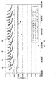
図1に、基本負荷以上の燃料電池セルの出力電流を、周期的かつ一時的に増加させたことによる効果を示す。ここで、スタックは、基本負荷である320(mA/cm2)で動作している。基本負荷は、燃料電池そのものによって燃料電池セルスタックに与えられる継続的な寄生負荷(すなわち制御回路やファンなど)とともに、燃料電池に対する外部の電流需要により決定されるものとする。燃料電池セルスタックへの周期的かつ一時的な電流需要の増加は、電流パルスとして現れる。このとき、スタック電流は、それぞれ2分間隔及び5分間隔で到来する約5秒間の加湿時間によって900(mA/cm2)まで増加した。全体的な効率改善は、50℃のH2の低位発熱量(LHV)に基づいており、高負荷における5秒間の加湿パルスの間は、ゼロ効率と仮定している。 In FIG. 1, the effect by having increased the output current of the fuel cell more than basic load periodically and temporarily is shown. Here, the stack is operating at a basic load of 320 (mA / cm 2 ). The basic load shall be determined by the external current demand on the fuel cell, along with the continuous parasitic load (ie, control circuit, fan, etc.) applied to the fuel cell stack by the fuel cell itself. The periodic and temporary increase in current demand for the fuel cell stack appears as a current pulse. At this time, the stack current increased to 900 (mA / cm 2 ) by the humidification time of about 5 seconds that arrived at intervals of 2 minutes and 5 minutes, respectively. The overall efficiency improvement is based on the low heating value (LHV) of H 2 at 50 ° C., assuming zero efficiency during the 5 second humidification pulse at high load.
320(mA/cm2)の定常状態の基本負荷では、図1の線分10で示すように、セル電圧は0.65(V)をやや上回り、低位発熱量は52.4(%)となる。2分間ごとに5秒間継続する加湿時間で動作したときのセル電圧は、図1の線分11で示される。これは、約4.2(%)の加湿のデューティーサイクル(duty cycle)に対応し、57.6(%)のLHVとなる。5分間ごとに5秒間継続する加湿時間で動作したときのセル電圧は、図1の線分12で示される。これは、約1.7(%)の加湿のデューティーサイクルに対応し、57.2(%)のLHVとなる。
In the steady state basic load of 320 (mA / cm 2 ), as shown by the
加湿時間後のセル電圧の急激な上昇及びその後の下降の程度は、図1から明らかである。性能改善は、燃料電池セルの水分維持の要素、特に、温度と、セルスタックに流れるエアフローとともに、高分子膜と、これに備わるガス拡散層の特性に依存する。加湿時間は、MEAに隣接して膜の保水レベルの制御及び維持を補助する高度拡散媒体(advanced diffusion media)とともに用いると、特に効果的である。すなわち、本発明は、UK特許出願0501598.7と、対応する国際特許出願PCT/GB2006/000074に記載された開放陰極式スタックの構成のような、水流の停止に役立つ複数層の拡散層の構成とともに用いると、特に有効である。図5に、(i)単層の陰極側拡散層を有する燃料電池セルと、(ii)複数層の陰極側拡散層を有する燃料電池セルとにおけるパルス電流動作について、燃料電池の性能改善を比較して示す。上部の軌跡は、(ii)の形態のセル電圧を示し、下部の軌跡は、(i)の形態のセル電圧を示す。加湿パルスは、10分ごとに発生している。 The extent of the rapid rise and subsequent fall of the cell voltage after the humidification time is apparent from FIG. The performance improvement depends on the characteristics of the water retention of the fuel cell, in particular the temperature and the air flow flowing through the cell stack, as well as the characteristics of the polymer membrane and the gas diffusion layer provided therein. The humidification time is particularly effective when used with an advanced diffusion media that helps control and maintain the water retention level of the membrane adjacent to the MEA. That is, the present invention provides a multi-layer diffusion layer configuration that helps stop water flow, such as the configuration of an open cathode stack described in UK patent application 0501598.7 and the corresponding international patent application PCT / GB2006 / 000074. It is particularly effective when used together. FIG. 5 compares the performance improvement of the fuel cell with respect to the pulse current operation in (i) a fuel cell having a single cathode side diffusion layer and (ii) a fuel cell having a plurality of cathode side diffusion layers. Show. The upper trace shows the cell voltage in the form (ii), and the lower trace shows the cell voltage in the form (i). Humidification pulses occur every 10 minutes.
図2に、加湿電流パルスが有る場合及び無い場合における、燃料電池セルのリアルタイムなセル電圧と平均セル電圧に対する影響を表している。セル電圧の軸は、スタック全体の平均セル電圧、つまり、スタック電圧をスタック内のセル数で割った値を表している。上部の直線20はセル電圧の時間平均であって、0.69(V)をやや上回っており、また、上部の軌跡21は瞬間セル電圧であり、ともに加湿時間を設けてスタックを動作させたときのものである。下部の直線22はセル電圧の時間平均であって、0.65(V)をやや上回っており、また、下部の軌跡23は瞬間セル電圧であり、ともに加湿時間を設けないでスタックを動作させたときのものである。下部の軌跡23には、上部の軌跡21とは異なる周波数の周期性が見られることに留意されたい。これは、両方の場合において、他の閉鎖式陽極の形態(closed-ended anode configuration)にある水構造体(water build up)を取り除くため、周期的に陽極の浄化が行われており、この浄化が下部の軌跡23では支配的だからである。周期的に閉鎖式陽極は、約1秒間で陽極から水分を除去するために無制限形態(open-ended configuration)へと切替えられる。しかしながら、平均電圧及び瞬間電圧20,21は、加湿時間の無い場合の等価電圧22,23を上回って、顕著な増加をみせていることから、加湿時間の効果は非常に明確である。
FIG. 2 shows the influence of the fuel cell on the real-time cell voltage and the average cell voltage with and without the humidifying current pulse. The cell voltage axis represents the average cell voltage of the entire stack, that is, the value obtained by dividing the stack voltage by the number of cells in the stack. The upper
燃料電池セルシステムにおいて加湿時間の効果を利用するためには、図3に示すような制御システムを追加する必要がある。 In order to utilize the effect of the humidifying time in the fuel cell system, it is necessary to add a control system as shown in FIG.
燃料電池30は、直列接続された所定数の燃料電池セル32を有する燃料電池セルスタックを含む。各燃料電池セル32は、従来の燃料電池セルスタックの設計に従って、膜電極接合体と、膜電極接合体に燃料及び酸化剤を供給するための流体フロープレートとを有している。出力部33は、燃料電池セルスタックからの出力電流を供給するため備えられている。冷却システム34は、例えばファンであり、冷却用エアフロー及び酸化剤をともにフロープレートへ供給する。燃料電池30からの電力は、リレー42,43を介して、電力の外部出力端子35により外部負荷41へと供給される。
The
内部の電気的負荷36は、電力制御部38の制御下にあるスイッチ37によって接続切替可能であって、周期的かつ一時的に燃料電池スタック31からの出力電流を増加させる。予備電源、すなわち電力「蓄積」部39は、リレー43を介して、出力端子35に接続され、燃料電池スタック31から内部負荷36に電力供給するように接続切替えが行われたときに、出力端子35に電力供給する。また、負荷制御回路40と冷却システム34は、電力制御部38の制御下にある。電力蓄積部39は、リチャージ可能なバッテリーであると好適であるが、スーパーキャパシタのような他の適当なチャージ式蓄積デバイスの類であってもよい。負荷制御回路40としては、DC−DCコンバータを用いるのが好ましい。
The internal
実際には、通常、燃料電池スタック31から外部負荷41に電力供給するように接続が切替えられており、内部負荷36と電力蓄積部39は、両方とも、燃料電池スタック31及び外部出力端子35から絶縁されている。
In practice, the connection is usually switched so as to supply power from the
しかしながら、電力制御部38は、加湿時間中に、リレー42を開き、スイッチ37を操作して、電力蓄積部39を燃料電池スタック31から絶縁させ、燃料電池スタック31からの電流を、内部負荷36へと方向転換させる。電力制御部38は、同時に、外部負荷41への電力供給を阻害しないように、リレー43を閉じた状態に維持し、電力蓄積部39と出力端子35との電気的接続を保ち、そこから外部負荷41へ電力供給がなされる。
加湿時間の最後に、電力制御部38は、スイッチ37とリレー42とを操作して、内部負荷36を燃料電池スタック31から絶縁させ、燃料電池スタックを出力端子41に再接続する。このとき、電力蓄積部39は、燃料電池スタック31との接続を維持し、燃料電池スタック31からの電流によってリチャージされるようにするとよい。適当なチャージ時間の後、負荷制御回路40は、3番目のリレー44を用いて、電力蓄積部39を絶縁させる動作を行う。これに代わり、電力蓄積部39を、単純に、常時、接続させたままでもよい。
However, during the humidification time, the
At the end of the humidification time, the
上述した内容から、燃料電池スタック31が主電源であるが、加湿時間中には、電力蓄積部39が、外部負荷41への唯一の電力供給源であることがわかる。燃料電池スタック31が供給ライン(on line)に戻ると、バッテリー39を満タンにリチャージすることができ、バッテリーが満タン状態に近づくにつれて、バッテリーに流れ込む電流は小さくなる。
From the above description, it can be seen that the
この構成は、様々な変形が可能である。例えば、加湿時間中に燃料電池スタック31及び内部負荷36を外部負荷41から絶縁させる必要がないのであれば、スイッチ37は、2方向スイッチである必要はない。言い換えると、加湿時間中でも外部負荷41に所要電力が供給されるとすれば、原理上、加湿時間中、内部負荷36を外部負荷41に単純に並列接続できる。この場合、加湿時間中でも燃料電池スタック31から外部負荷41への電流は維持されるから、電力蓄積部39は、厳密には必要がない。同様に、出力端子35を燃料電池スタック31に直接接続することができる。つまり、第1の並列回路の内部負荷36は、要求に従い、接続状態と非接続状態に切り替わり、また、第2の並列回路の電力蓄積部は、要求に従い、チャージ制御によって接続状態と非接続状態に切り替わる。
This configuration can be variously modified. For example, if it is not necessary to insulate the
上述したように、一般的な見地から、スタック電力制御部38は、内部負荷36を用いて、加湿時間中に、燃料電池外部の独立した電流需要に加えて、又は、この電流需要に代わって、周期的かつ一時的に燃料電池スタックからの出力電流を増加させる。必要であれば、スイッチング時の大きな過渡電流を避けるために、パワーコントロールデバイスを用いて、制御に基づくスイッチングにより内部負荷36を接続してもよい。
As described above, from a general point of view, the stack
また、加湿時間は、燃料電池セルスタック31の陰極に流すエアフローを周期的に弱めることによって設けることもできる。すなわち、電力制御部38によって、加湿時間中に冷却用ファン34への供給電力を低下させればよい。好ましくは、加湿時間中に冷却用ファンのスイッチを切るのがよい。
Further, the humidifying time can be provided by periodically weakening the air flow that flows to the cathode of the
すなわち、一般的な見地から、スタック電力制御部38は、燃料電池セルスタックに対する電流需要とは関係なく、周期的に燃料電池セルスタック31に流すエアフローを調節することによって、燃料電池セルの保湿レベルを増加させる加湿時間を設ける。ここでいう「関係なく」という表現は、燃料電池30の外部負荷41の急な変化、又は一時的な変化とは無関係であることを示すものである。
That is, from a general point of view, the stack
エアフローの調節と負荷の増加は、ともに加湿時間を設けるという目的のために行われる。図4のグラフは、この動作における電流及び電圧特性である。上部の軌跡50は、スタック電圧を時間関数として示しており、下部の軌跡51は、スタック電流を時間関数として示している。
Both air flow regulation and load increase are performed for the purpose of providing humidification time. The graph of FIG. 4 shows current and voltage characteristics in this operation. The
時間52(t=0−6秒)では、燃料電池の通常動作を示している。次の時間53(t=6−10秒)では、陰極のエアフローを生成する冷却用ファン34のスイッチが切られ、スタック温度が上昇する。多くの移動制限のために、この時間の終わりに近づくにつれて、セル電圧に若干の低下が見られ、これに対応して、一定の電力を維持するように、電流に若干の上昇が見られる。DC−DCコンバータ40への入力電圧がバッテリー39の終端電圧に近づくところでは、燃料電池セルからの出力電流が0に向かって低下している。ここでは、バッテリー39が、出力端子35への電力供給を支えて補っている。
At time 52 (t = 0-6 seconds), the normal operation of the fuel cell is shown. At the next time 53 (t = 6-10 seconds), the cooling
そして、燃料電池セルスタック31からの出力を、最小の電気的負荷のもとでリレー42を開いて絶縁し、バッテリー39からアプリケーション(例えば外部負荷41)に継続的に電力供給させておく。これは、時間54(t=10−11秒)で、電流が0に落ちていることからわかる。時間t=11秒では、スパイク55からわかるように、内部負荷抵抗36が、燃料電池セルスタック31の両端子33に接続切替されている。これにより、燃料電池セルスタック31には、さらに制御時間、言い換えると高電流時間56(t=11−12秒)でも電気的負荷が与えられる。
Then, the output from the
この高電流時間56中、燃料電池セルスタック31の流体フローチャネルに残った酸化剤は消費されて、スタックの端子電圧は0(V)に低下する。生成水を除去するファン34がなければ、各セル31のMEA−ガス拡散層インターフェースに過剰水が滞留してしまう。高電流時間56の後、絶縁時間(t=12−16秒)では、燃料電池セルスタック31は、全ての電気的負荷から絶縁される。この絶縁時間中、電流は0であり、スタック電圧は、ポイント58(t=16秒)にあるピークまで回復する。再接続時間(t=16−18秒)では、DC−DCコンバータ40のデジタル制御により電流の限界設定点を徐々に上げていき、制御された方法によってスタック31の出力電力が供給ラインに戻される。ポイント60では、燃料電池セルは、完全に供給ラインにあり、バッテリー39のリチャージを始めている(t=18秒)。燃料電池セルは、バッテリーのリチャージとともに、次の時間61中に外部負荷41に電力供給する。バッテリー39が、チャージにより満タンに近づくにつれ、電流は徐々に低下する。
During this high
次の加湿時間は、適当な間隔(例えば2−5秒)をおいてから始まる。間隔は、有効にセル電圧の平均を十分に上昇させるのであれば、いくらでもよい。温度及び湿度のような周囲条件と、燃料電池セルが一定の固定負荷、又は可変負荷のどちらで動作しているかとに依存して、例えば、ほんの1分間という短い間隔とすることができるし、2時間もの長い間隔とすることもできる。 The next humidification time begins after a suitable interval (eg 2-5 seconds). The interval may be any number as long as it effectively increases the average cell voltage. Depending on ambient conditions such as temperature and humidity and whether the fuel cell is operating at a fixed load or a variable load, for example, it can be as short as 1 minute, The interval can be as long as 2 hours.
加湿処理の理想的な周期は、温度及び湿度のような周囲条件を含む多くの要素に依存する。複数層の陰極側ガス拡散層を用いると、単層のガス拡散層の構成と比較して、電気化学的性能が格段に増加し、燃料電池セルの性能が同等レベルにまで戻るには長い時間がかかる。これは、従来の圧縮陰極とは反対に、開放陰極のスタックを用いる技術を使う場合でもある。圧縮陰極の場合は、強制的にエアフローを流すことにより即時に過剰水が除去される。 The ideal cycle of the humidification process depends on many factors including ambient conditions such as temperature and humidity. When multiple cathode side gas diffusion layers are used, the electrochemical performance is significantly increased compared to the configuration of a single gas diffusion layer, and it takes a long time for the fuel cell performance to return to the same level. It takes. This is also the case when using techniques that use a stack of open cathodes, as opposed to conventional compressed cathodes. In the case of a compressed cathode, excess water is immediately removed by forcing an air flow.
加湿処理は、自動的に固定周期で実行されるのがよい。しかしながら、燃料電池30を、加湿処理が行なわれない通常モードと、周期的かつ一時的に加湿処理を行う加湿モードの間で切替えるためには、さらなる制御アルゴリズムが用られることを理解されたい。加湿処理の周期は、平均温度、湿度、電圧特性、電流特性、電力需要などのような、スタックの測定可能な動作パラメータに従って制御される。加湿時間のデューティーサイクルは、平均温度、湿度、電圧特性、電流特性、電力需要などのような、スタックの測定可能な動作パラメータに従って制御される。絶縁時間57中の出力電流は0であるのがよいが、低電流が出力されうることを理解されたい。具体例によっては、絶縁時間は不要である。
The humidification process is preferably performed automatically at a fixed period. However, it should be understood that additional control algorithms are used to switch the
他の実施例が添付の特許請求の範囲に記載されている。 Other embodiments are in the appended claims.
Claims (13)
前記燃料電池セルスタック(31)は、所定数の燃料電池セル(32)と、電気的な出力部(33)とを含み、
前記燃料電池セル(32)は、膜電極接合体と、前記膜電極接合体に燃料及び酸化剤を供給するための流体フロープレートとを有し、
前記出力部(33)は、前記燃料電池セルスタック(31)からの出力電流を供給するためのものであり、
前記スタック電力制御部(38)は、
前記出力部(33)に対して接続切替可能な負荷デバイス(36)を含み、
高電流時間と、前記高電流時間に続く絶縁時間とを含む加湿時間が設けられるように制御し、
(i)前記高電流時間中、前記燃料電池セルスタック(31)から前記接続切替可能な負荷デバイス(36)を介して電流を流すことにより、燃料電池外部の独立した電流需要(41)に加えて、又は、この電流需要(41)に代わって、周期的、かつ、一時的に前記燃料電池セルスタック(31)からの出力電流を増加させる制御を行うことによって、前記燃料電池セル(32)の保湿レベルを増加させ、
(ii)前記絶縁時間中、前記燃料電池セルスタック(31)の出力電流が通常動作の電流需要より低くなるように、前記燃料電池セルスタック(31)を前記負荷デバイス(36)、及び、前記燃料電池外部の独立した電流需要(41)から絶縁し、前記燃料電池セルスタック(31)の電圧を回復させる、
電気化学燃料電池。 An electrochemical fuel cell (30) including a fuel cell stack (31) and a stack power control unit (38),
The fuel cell stack (31) includes a predetermined number of fuel cells (32) and an electrical output (33),
The fuel cell (32) has a membrane electrode assembly and a fluid flow plate for supplying fuel and an oxidant to the membrane electrode assembly,
The output section (33) is for supplying an output current from the fuel cell stack (31),
The stack power control unit (38)
A load device (36) capable of switching connection to the output unit (33) ;
Control to provide a humidifying time including a high current time and an insulation time following the high current time,
(I) In addition to the independent current demand (41) outside the fuel cell by flowing current from the fuel cell stack (31) via the switchable load device (36) during the high current time Alternatively, instead of the current demand (41), the fuel cell (32) is controlled by periodically and temporarily increasing the output current from the fuel cell stack (31). Increase the moisturizing level of
(Ii) The fuel cell stack (31) is connected to the load device (36) and the fuel cell stack (31) so that the output current of the fuel cell stack (31) is lower than the current demand for normal operation during the insulation time. Insulate from an independent current demand (41) outside the fuel cell and restore the voltage of the fuel cell stack (31);
Electrochemical fuel cell.
さらに電力蓄積部(39)を含み、
前記電力蓄積部(39)は、前記出力部(33)からの電力を、前記燃料電池外部の独立した電流需要(41)に対して供給する外部出力端子(35)に接続され、
前記スタック電力制御部(38)は、前記加湿時間中に、燃料電池セルスタック(31)の前記出力部(33)を前記外部出力端子(35)から絶縁する制御を行う、
電気化学燃料電池。 The electrochemical fuel cell according to claim 1,
In addition, it includes a power storage unit (39),
The power storage unit (39) is connected to an external output terminal (35) that supplies power from the output unit (33) to an independent current demand (41) outside the fuel cell ,
The stack power control unit (38) performs control to insulate the output unit (33) of the fuel cell stack (31) from the external output terminal (35) during the humidification time.
Electrochemical fuel cell.
さらに電力蓄積部(39)と負荷制御デバイス(40)とを含み、
前記電力蓄積部は、燃料電池(30)の電力の外部出力端子(35)に接続され、
前記負荷制御デバイス(40)は、前記電力蓄積部(39)と前記燃料電池スタック(31)の何れか一方、又は両方から燃料電池の前記外部出力端子(35)への電流の供給を制御する、
電気化学燃料電池。 The electrochemical fuel cell according to claim 1,
Furthermore, it includes a power storage unit (39) and a load control device (40),
The power storage unit is connected to an external output terminal (35) of power of the fuel cell (30),
The load control device (40) controls supply of current from the power storage unit (39) and / or the fuel cell stack (31) to the external output terminal (35) of the fuel cell. ,
Electrochemical fuel cell.
前記電力蓄積部(39)は、リチャージ可能なバッテリーである、
電気化学燃料電池。 The electrochemical fuel cell according to claim 2 or 3,
The power storage unit (39) is a rechargeable battery.
Electrochemical fuel cell.
前記スタック電力制御部(38)は、前記加湿時間が規則的な時間で到来するように制御する、
電気化学燃料電池。 The electrochemical fuel cell according to claim 1,
The stack power control unit (38) controls the humidification time to arrive at a regular time.
Electrochemical fuel cell.
前記スタック電力制御部(38)は、基準内にある前記燃料電池スタックのパラメータに応じて、前記加湿時間が設けられるように制御する、
電気化学燃料電池。 The electrochemical fuel cell according to claim 1 or 5,
The stack power control unit (38) controls the humidification time to be provided according to parameters of the fuel cell stack within a standard.
Electrochemical fuel cell.
前記負荷制御デバイス(40)は、前記加湿時間の後、前記燃料電池スタックから前記外部出力端子(35)への電力供給を立ち上げる制御を行う、
電気化学燃料電池。 The electrochemical fuel cell according to claim 3,
The load control device (40) performs control for starting up power supply from the fuel cell stack to the external output terminal (35) after the humidification time.
Electrochemical fuel cell.
前記スタック電力制御部は、前記加湿時間中、前記燃料電池スタック(31)の前記流体フロープレートに流すエアフローを調節する制御を行う、
電気化学燃料電池。 The electrochemical fuel cell according to claim 1,
The stack power control unit performs control to adjust an air flow flowing through the fluid flow plate of the fuel cell stack (31) during the humidification time.
Electrochemical fuel cell.
前記燃料電池セルスタックは、所定数の燃料電池セル(32)と、電気的な出力部(33)とを含み、
前記燃料電池セルは、膜電極接合体と、前記膜電極接合体に燃料及び酸化剤を供給するための流体フロープレートとを有し、
前記出力部は、前記燃料電池セルスタックからの出力電流を前記燃料電池の外部の負荷に供給するためのものであり、
前記スタック制御部は、燃料電池に対する電流需要とは関係なく、周期的に前記燃料電池セルスタック(31)に流すエアフローを調節する制御を行うことによって、前記燃料電池セルの保湿レベルを増加させる加湿時間を設け、
前記加湿時間は、高電流時間と、前記高電流時間に続く絶縁時間とを含み、
前記スタック制御部は、さらに、前記出力部に対して接続切替可能な負荷デバイス(36)を含み、
(i)前記高電流時間において、前記負荷デバイスを介して、一時的に前記燃料電池スタックからの出力電流を増加させる制御を行うことによって、前記燃料電池セルの保湿レベルを増加させ、
(ii)前記絶縁時間において、前記燃料電池スタックの出力電流が通常動作の電流需要より低くなるように、前記燃料電池セルスタックを前記負荷デバイス、及び、前記燃料電池の外部の負荷から絶縁し、前記燃料電池セルスタックの電圧を回復させ、
前記維持手段は、前記加湿時間中、前記燃料電池外部の負荷の電流需要を支える制御を行う、
電気化学燃料電池。 An electrochemical fuel cell (30) comprising a fuel cell stack (31), a stack controller (38), and a maintenance means,
The fuel cell stack includes a predetermined number of fuel cells (32) and an electrical output (33),
The fuel cell has a membrane electrode assembly and a fluid flow plate for supplying fuel and an oxidant to the membrane electrode assembly,
The output unit is for supplying an output current from the fuel cell stack to a load outside the fuel cell ,
The stack control unit performs control to periodically adjust the air flow flowing through the fuel cell stack (31) regardless of the current demand for the fuel cell, thereby increasing the moisture retention level of the fuel cell. Have time,
The humidification time includes a high current time and an insulation time following the high current time,
The stack control unit further includes a load device (36) capable of switching connection to the output unit,
(I) In the high current time, by performing control to temporarily increase the output current from the fuel cell stack via the load device, the moisture retention level of the fuel cell is increased,
(Ii) isolating the fuel cell stack from the load device and a load external to the fuel cell so that the output current of the fuel cell stack is lower than the current demand for normal operation during the insulation time; Recover the voltage of the fuel cell stack,
Said maintaining means, during the rehydration interval, it performs control to support the current demand of the fuel cell external load,
Electrochemical fuel cell.
前記燃料電池セルスタックは、所定数の燃料電池セル(32)と、電気的な出力部(33)とを含み、
前記燃料電池セルは、膜電極接合体と、前記膜電極接合体に燃料及び酸化剤を供給するための流体フロープレートとを有し、
前記出力部は、前記燃料電池セルスタックからの出力電流を前記燃料電池の外部の負荷(41)に供給するためのものであり、
加湿時間のうち高電流時間中に前記燃料電池セルスタックから燃料電池内部の前記出力部に対して接続切替可能な負荷デバイス(36)を介して電流を流すことにより、燃料電池外部の電流需要とは関係なく、加湿時間中に、周期的かつ一時的に前記燃料電池スタックからの出力電流を増加させることによって、前記燃料電池セルの保湿レベルを増加させるステップと、
前記加湿時間中に、前記高電流時間に続く絶縁時間が設けられるように制御し、前記絶縁時間において、前記燃料電池スタックの出力電流が通常動作の電流需要より低くなるように、前記燃料電池セルスタックを前記負荷デバイス、及び、前記燃料電池の外部の負荷から絶縁し、前記燃料電池セルスタックの電圧を回復させるステップと、
前記加湿時間中、前記燃料電池の外部の負荷の電流需要を支えるステップとを含む、
電気化学燃料電池の動作方法。 A method of operating an electrochemical fuel cell (30) having a fuel cell stack (31) comprising:
The fuel cell stack includes a predetermined number of fuel cells (32) and an electrical output (33),
The fuel cell has a membrane electrode assembly and a fluid flow plate for supplying fuel and an oxidant to the membrane electrode assembly,
The output unit is for supplying an output current from the fuel cell stack to a load (41) outside the fuel cell ,
By flowing current from the fuel cell stack through the load device (36) that can be switched to the output unit inside the fuel cell during the high current time in the humidification time, Regardless of increasing the moisture retention level of the fuel cell by periodically and temporarily increasing the output current from the fuel cell stack during the humidification time;
The fuel cell is controlled so that an insulation time following the high current time is provided during the humidification time, and the output current of the fuel cell stack is lower than the current demand for normal operation during the insulation time. Isolating the stack from the load device and a load external to the fuel cell and restoring the voltage of the fuel cell stack;
Supporting a current demand of a load external to the fuel cell during the humidification time,
Method of operating an electrochemical fuel cell.
前記加湿時間中の電流需要を支えるステップには、電力蓄積部(39)の使用が含まれる、
電気化学燃料電池の動作方法。 An operation method of an electrochemical fuel cell according to claim 10,
The step of supporting the current demand during the humidifying time includes the use of a power storage unit (39).
Method of operating an electrochemical fuel cell.
前記燃料電池セルスタックは、所定数の燃料電池セル(32)と、電気的な出力部(33)とを含み、
前記燃料電池セルは、膜電極接合体と、前記膜電極接合体に燃料及び酸化剤を供給するための流体フロープレートとを有し、
前記出力部は、前記燃料電池セルスタックからの出力電流を前記燃料電池の外部の負荷(41)に供給するためのものであり、
前記負荷デバイスは、前記出力部に対して接続切替可能であり、
燃料電池に対する電流需要とは関係なく、周期的に前記燃料電池セルスタックに流すエアフローを調節することによって、前記燃料電池セルの保湿レベルを増加させる加湿時間を設け、前記加湿時間中、前記燃料電池外部の負荷の電流需要を支えるステップと、
前記加湿時間中に、高電流時間と、前記高電流時間に続く絶縁時間とが設けられるように制御し、
(i)前記高電流時間において、前記負荷デバイスを介して、一時的に前記燃料電池スタックからの出力電流を増加させる制御を行うことによって、前記燃料電池セルの保湿レベルを増加させ、
(ii)前記絶縁時間において、前記燃料電池スタックの出力電流が通常動作の電流需要より低くなるように、前記燃料電池セルスタックを前記負荷デバイス、及び、前記燃料電池の外部の負荷から絶縁し、前記燃料電池セルスタックの電圧を回復させる
ステップとを含む、
電気化学燃料電池の動作方法。 A method of operating an electrochemical fuel cell (30) having a fuel cell stack (31) and a load device (36) , comprising:
The fuel cell stack includes a predetermined number of fuel cells (32) and an electrical output (33),
The fuel cell has a membrane electrode assembly and a fluid flow plate for supplying fuel and an oxidant to the membrane electrode assembly,
The output unit is for supplying an output current from the fuel cell stack to a load (41) outside the fuel cell ,
The load device is switchable for connection to the output unit,
Regardless of the current demand for the fuel cell, a humidifying time for increasing the moisture retention level of the fuel cell is provided by periodically adjusting the air flow flowing through the fuel cell stack, and the fuel cell is used during the humidifying time. Steps to support the current demand of external loads ,
During the humidification time, control is performed so that a high current time and an insulation time following the high current time are provided,
(I) In the high current time, by performing control to temporarily increase the output current from the fuel cell stack via the load device, the moisture retention level of the fuel cell is increased,
(Ii) isolating the fuel cell stack from the load device and a load external to the fuel cell so that the output current of the fuel cell stack is lower than the current demand for normal operation during the insulation time; Recovering the voltage of the fuel cell stack.
Method of operating an electrochemical fuel cell.
前記加湿時間中の電流需要を支えるステップには、電力蓄積部(39)の使用が含まれる、
電気化学燃料電池の動作方法。
An operation method of an electrochemical fuel cell according to claim 12, comprising:
The step of supporting the current demand during the humidifying time includes the use of a power storage unit (39).
Method of operating an electrochemical fuel cell.
Applications Claiming Priority (3)
| Application Number | Priority Date | Filing Date | Title |
|---|---|---|---|
| GB0604241A GB2435711B (en) | 2006-03-03 | 2006-03-03 | Rehydration of fuel cells |
| GB0604241.0 | 2006-03-03 | ||
| PCT/GB2007/000760 WO2007099360A2 (en) | 2006-03-03 | 2007-03-05 | Rehydration of fuel cells |
Publications (3)
| Publication Number | Publication Date |
|---|---|
| JP2009528657A JP2009528657A (en) | 2009-08-06 |
| JP2009528657A5 JP2009528657A5 (en) | 2010-04-15 |
| JP5580991B2 true JP5580991B2 (en) | 2014-08-27 |
Family
ID=36219027
Family Applications (1)
| Application Number | Title | Priority Date | Filing Date |
|---|---|---|---|
| JP2008556856A Active JP5580991B2 (en) | 2006-03-03 | 2007-03-05 | Humidification of fuel cells |
Country Status (18)
| Country | Link |
|---|---|
| US (1) | US8263277B2 (en) |
| EP (2) | EP2161773B1 (en) |
| JP (1) | JP5580991B2 (en) |
| KR (1) | KR101486902B1 (en) |
| CN (1) | CN101411022B (en) |
| AR (2) | AR059744A1 (en) |
| AT (1) | ATE487245T1 (en) |
| BR (1) | BRPI0708440A2 (en) |
| CA (2) | CA2644342C (en) |
| DE (1) | DE602007010248D1 (en) |
| ES (2) | ES2397784T3 (en) |
| GB (1) | GB2435711B (en) |
| MX (1) | MX2008011288A (en) |
| NO (1) | NO20083625L (en) |
| RU (1) | RU2417486C2 (en) |
| TW (1) | TWI401837B (en) |
| WO (1) | WO2007099360A2 (en) |
| ZA (1) | ZA200807462B (en) |
Families Citing this family (8)
| Publication number | Priority date | Publication date | Assignee | Title |
|---|---|---|---|---|
| US9444113B2 (en) | 2011-02-16 | 2016-09-13 | Toyota Jidosha Kabushiki Kaisha | Fuel cell system with water production control, and vehicle equipped with the same |
| GB2513636A (en) * | 2013-05-02 | 2014-11-05 | Intelligent Energy Ltd | A fuel cell system |
| JP6341123B2 (en) * | 2015-03-16 | 2018-06-13 | スズキ株式会社 | Fuel cell humidifier and fuel cell motorcycle |
| GB2543031A (en) * | 2015-09-29 | 2017-04-12 | Intelligent Energy Ltd | Fuel cell system controller and associated method |
| CN105720283A (en) * | 2016-04-07 | 2016-06-29 | 北京建筑大学 | Fuel cell hybrid power system and working method thereof |
| WO2017195045A2 (en) | 2016-04-14 | 2017-11-16 | Intelligent Energy Limited | Pem fuel cell power systems with efficient hydrogen generation |
| WO2018046990A1 (en) | 2016-09-07 | 2018-03-15 | Intelligent Energy Limited | Ground stations and methods for pem fuel cell powered unmanned aerial vehicles |
| WO2019050959A1 (en) | 2017-09-05 | 2019-03-14 | Intelligent Energy Inc. | Compact efficient hydrogen reactor |
Family Cites Families (19)
| Publication number | Priority date | Publication date | Assignee | Title |
|---|---|---|---|---|
| US3432356A (en) * | 1963-09-11 | 1969-03-11 | Gen Electric | Regulated fuel cell system |
| JP2001513940A (en) * | 1998-03-06 | 2001-09-04 | マグネート−モートア、ゲゼルシャフト、フュール、マグネートモートリシェ、テヒニク、ミット、ベシュレンクテル、ハフツング | Gas diffusion electrode and polymer electrolyte membrane fuel cell with low water diffusion capacity |
| US6214487B1 (en) * | 1999-02-01 | 2001-04-10 | Motorola, Inc. | Integral sensors for monitoring a fuel cell membrane and methods of monitoring |
| WO2001028022A1 (en) * | 1999-10-14 | 2001-04-19 | Motorola Inc. | Method and apparatus for managing hydration level of fuel cell electrolyte |
| US6589682B1 (en) * | 2000-01-27 | 2003-07-08 | Karen Fleckner | Fuel cells incorporating nanotubes in fuel feed |
| JP2001229943A (en) * | 2000-02-14 | 2001-08-24 | Nissan Motor Co Ltd | Fuel cell system |
| US6835481B2 (en) * | 2000-03-29 | 2004-12-28 | Idatech, Llc | Fuel cell system with load management |
| US20030003341A1 (en) * | 2001-06-29 | 2003-01-02 | Kinkelaar Mark R. | Liquid fuel cell reservoir for water and/or fuel management |
| GB2412784B (en) * | 2002-01-18 | 2006-08-23 | Intelligent Energy Ltd | Fuel cell oxygen removal and pre-conditioning system |
| JP4193521B2 (en) | 2002-03-20 | 2008-12-10 | ソニー株式会社 | FUEL CELL DEVICE AND FUEL CELL CONTROL METHOD |
| TW558852B (en) | 2002-07-12 | 2003-10-21 | Asia Pacific Fuel Cell Tech | Control apparatus and method of fuel cell set |
| TW550851B (en) * | 2002-07-17 | 2003-09-01 | Asia Pacific Fuel Cell Tech | Fuel battery having moisturizing module |
| US7318971B2 (en) * | 2003-02-14 | 2008-01-15 | Denso Corporation | Fuel cell system utilizing control of operating current to adjust moisture content within fuel cell |
| JP4608892B2 (en) * | 2003-02-14 | 2011-01-12 | 株式会社デンソー | Fuel cell system |
| JP2005085532A (en) * | 2003-09-05 | 2005-03-31 | Nissan Motor Co Ltd | Fuel cell system |
| US7297428B2 (en) * | 2003-10-31 | 2007-11-20 | 3M Innovative Properties Company | Registration arrangement for fuel cell assemblies |
| US7270900B2 (en) | 2003-11-03 | 2007-09-18 | Mti Microfuel Cells, Inc. | Automatic measurement of fuel cell resistance |
| JP2006079955A (en) * | 2004-09-10 | 2006-03-23 | Casio Comput Co Ltd | Fuel cell system, and container for power generating fuel |
| US7754361B2 (en) * | 2007-05-30 | 2010-07-13 | Idatech, Llc | Fuel cell systems with maintenance hydration by displacement of primary power |
-
2006
- 2006-03-03 GB GB0604241A patent/GB2435711B/en not_active Expired - Fee Related
-
2007
- 2007-03-02 TW TW096107160A patent/TWI401837B/en active
- 2007-03-05 KR KR1020087024088A patent/KR101486902B1/en active IP Right Grant
- 2007-03-05 RU RU2008139284/07A patent/RU2417486C2/en not_active IP Right Cessation
- 2007-03-05 MX MX2008011288A patent/MX2008011288A/en active IP Right Grant
- 2007-03-05 ES ES09014297T patent/ES2397784T3/en active Active
- 2007-03-05 DE DE602007010248T patent/DE602007010248D1/en active Active
- 2007-03-05 CA CA2644342A patent/CA2644342C/en active Active
- 2007-03-05 CN CN2007800076761A patent/CN101411022B/en active Active
- 2007-03-05 CA CA2826749A patent/CA2826749C/en not_active Expired - Fee Related
- 2007-03-05 AT AT07731980T patent/ATE487245T1/en not_active IP Right Cessation
- 2007-03-05 BR BRPI0708440-4A patent/BRPI0708440A2/en not_active Application Discontinuation
- 2007-03-05 EP EP09014297A patent/EP2161773B1/en active Active
- 2007-03-05 AR ARP070100906A patent/AR059744A1/en active IP Right Grant
- 2007-03-05 WO PCT/GB2007/000760 patent/WO2007099360A2/en active Application Filing
- 2007-03-05 ES ES07731980T patent/ES2370126T3/en active Active
- 2007-03-05 US US12/224,695 patent/US8263277B2/en active Active
- 2007-03-05 JP JP2008556856A patent/JP5580991B2/en active Active
- 2007-03-05 EP EP07731980A patent/EP1992037B1/en active Active
-
2008
- 2008-08-22 NO NO20083625A patent/NO20083625L/en not_active Application Discontinuation
- 2008-08-29 ZA ZA200807462A patent/ZA200807462B/en unknown
-
2013
- 2013-03-05 AR ARP130100724A patent/AR090255A2/en not_active Application Discontinuation
Also Published As
Similar Documents
| Publication | Publication Date | Title |
|---|---|---|
| JP5580991B2 (en) | Humidification of fuel cells | |
| TWI298957B (en) | Fuel cell apparatus | |
| US20080160370A1 (en) | Adaptive Current Controller for a Fuel-Cell System | |
| JP5480107B2 (en) | Method of operating a fuel cell / battery passive hybrid power supply | |
| US20070224482A1 (en) | Fuel Cell System | |
| WO2008057832A1 (en) | Fuel cell hibernation mode method and apparatus | |
| JP2010103076A (en) | Current collecting device for fuel cell, and method for controlling the same | |
| JP5492460B2 (en) | Reversible cell operation method | |
| JP2007059120A (en) | Fuel battery system | |
| JP2009528657A5 (en) | ||
| JPH11176454A (en) | Power source for fuel cell accessory | |
| JP3583914B2 (en) | Auxiliary power supply for fuel cell | |
| JP2007103114A (en) | Operation method of fuel cell system | |
| JP2000277136A (en) | Solid polymer type fuel cell and method for activating solid polymer type fuel cell | |
| JP2007280678A (en) | Fuel cell | |
| KR101572033B1 (en) | Apparatus for activating of fuel cell stack | |
| JP2012129081A (en) | Operational method of fuel cell system | |
| KR20090039441A (en) | Fuel cell system and starting method thereof | |
| JP2021184362A (en) | Fuel cell system | |
| KR20080044429A (en) | Fuel cell system and emergency driving method | |
| KR20130088986A (en) | Power apparatus using cell |
Legal Events
| Date | Code | Title | Description |
|---|---|---|---|
| A521 | Request for written amendment filed |
Free format text: JAPANESE INTERMEDIATE CODE: A523 Effective date: 20100215 |
|
| A621 | Written request for application examination |
Free format text: JAPANESE INTERMEDIATE CODE: A621 Effective date: 20100215 |
|
| A521 | Request for written amendment filed |
Free format text: JAPANESE INTERMEDIATE CODE: A523 Effective date: 20100225 |
|
| A977 | Report on retrieval |
Free format text: JAPANESE INTERMEDIATE CODE: A971007 Effective date: 20120731 |
|
| A131 | Notification of reasons for refusal |
Free format text: JAPANESE INTERMEDIATE CODE: A131 Effective date: 20120822 |
|
| A601 | Written request for extension of time |
Free format text: JAPANESE INTERMEDIATE CODE: A601 Effective date: 20121116 |
|
| A602 | Written permission of extension of time |
Free format text: JAPANESE INTERMEDIATE CODE: A602 Effective date: 20121126 |
|
| A521 | Request for written amendment filed |
Free format text: JAPANESE INTERMEDIATE CODE: A523 Effective date: 20130110 |
|
| A131 | Notification of reasons for refusal |
Free format text: JAPANESE INTERMEDIATE CODE: A131 Effective date: 20130703 |
|
| A521 | Request for written amendment filed |
Free format text: JAPANESE INTERMEDIATE CODE: A523 Effective date: 20130930 |
|
| A131 | Notification of reasons for refusal |
Free format text: JAPANESE INTERMEDIATE CODE: A131 Effective date: 20140226 |
|
| A521 | Request for written amendment filed |
Free format text: JAPANESE INTERMEDIATE CODE: A523 Effective date: 20140514 |
|
| TRDD | Decision of grant or rejection written | ||
| A01 | Written decision to grant a patent or to grant a registration (utility model) |
Free format text: JAPANESE INTERMEDIATE CODE: A01 Effective date: 20140625 |
|
| A61 | First payment of annual fees (during grant procedure) |
Free format text: JAPANESE INTERMEDIATE CODE: A61 Effective date: 20140714 |
|
| R150 | Certificate of patent or registration of utility model |
Ref document number: 5580991 Country of ref document: JP Free format text: JAPANESE INTERMEDIATE CODE: R150 |
|
| R250 | Receipt of annual fees |
Free format text: JAPANESE INTERMEDIATE CODE: R250 |
|
| R250 | Receipt of annual fees |
Free format text: JAPANESE INTERMEDIATE CODE: R250 |
|
| R250 | Receipt of annual fees |
Free format text: JAPANESE INTERMEDIATE CODE: R250 |
|
| R250 | Receipt of annual fees |
Free format text: JAPANESE INTERMEDIATE CODE: R250 |
|
| R250 | Receipt of annual fees |
Free format text: JAPANESE INTERMEDIATE CODE: R250 |
|
| R250 | Receipt of annual fees |
Free format text: JAPANESE INTERMEDIATE CODE: R250 |
|
| R250 | Receipt of annual fees |
Free format text: JAPANESE INTERMEDIATE CODE: R250 |