RU2389543C2 - Corrosionproof fluid flow conducting parts and method to replace equipment and parts using corrosionproof fluid flow conducting parts - Google Patents
Corrosionproof fluid flow conducting parts and method to replace equipment and parts using corrosionproof fluid flow conducting parts Download PDFInfo
- Publication number
- RU2389543C2 RU2389543C2 RU2007107805/15A RU2007107805A RU2389543C2 RU 2389543 C2 RU2389543 C2 RU 2389543C2 RU 2007107805/15 A RU2007107805/15 A RU 2007107805/15A RU 2007107805 A RU2007107805 A RU 2007107805A RU 2389543 C2 RU2389543 C2 RU 2389543C2
- Authority
- RU
- Russia
- Prior art keywords
- welding
- section
- cylinder
- titanium
- zirconium
- Prior art date
Links
Images

Classifications
-
- B—PERFORMING OPERATIONS; TRANSPORTING
- B01—PHYSICAL OR CHEMICAL PROCESSES OR APPARATUS IN GENERAL
- B01J—CHEMICAL OR PHYSICAL PROCESSES, e.g. CATALYSIS OR COLLOID CHEMISTRY; THEIR RELEVANT APPARATUS
- B01J19/00—Chemical, physical or physico-chemical processes in general; Their relevant apparatus
- B01J19/02—Apparatus characterised by being constructed of material selected for its chemically-resistant properties
-
- B—PERFORMING OPERATIONS; TRANSPORTING
- B23—MACHINE TOOLS; METAL-WORKING NOT OTHERWISE PROVIDED FOR
- B23K—SOLDERING OR UNSOLDERING; WELDING; CLADDING OR PLATING BY SOLDERING OR WELDING; CUTTING BY APPLYING HEAT LOCALLY, e.g. FLAME CUTTING; WORKING BY LASER BEAM
- B23K15/00—Electron-beam welding or cutting
- B23K15/04—Electron-beam welding or cutting for welding annular seams
-
- B—PERFORMING OPERATIONS; TRANSPORTING
- B01—PHYSICAL OR CHEMICAL PROCESSES OR APPARATUS IN GENERAL
- B01J—CHEMICAL OR PHYSICAL PROCESSES, e.g. CATALYSIS OR COLLOID CHEMISTRY; THEIR RELEVANT APPARATUS
- B01J19/00—Chemical, physical or physico-chemical processes in general; Their relevant apparatus
- B01J19/24—Stationary reactors without moving elements inside
- B01J19/2415—Tubular reactors
-
- B—PERFORMING OPERATIONS; TRANSPORTING
- B21—MECHANICAL METAL-WORKING WITHOUT ESSENTIALLY REMOVING MATERIAL; PUNCHING METAL
- B21C—MANUFACTURE OF METAL SHEETS, WIRE, RODS, TUBES OR PROFILES, OTHERWISE THAN BY ROLLING; AUXILIARY OPERATIONS USED IN CONNECTION WITH METAL-WORKING WITHOUT ESSENTIALLY REMOVING MATERIAL
- B21C23/00—Extruding metal; Impact extrusion
- B21C23/02—Making uncoated products
- B21C23/04—Making uncoated products by direct extrusion
- B21C23/08—Making wire, bars, tubes
- B21C23/085—Making tubes
-
- B—PERFORMING OPERATIONS; TRANSPORTING
- B21—MECHANICAL METAL-WORKING WITHOUT ESSENTIALLY REMOVING MATERIAL; PUNCHING METAL
- B21C—MANUFACTURE OF METAL SHEETS, WIRE, RODS, TUBES OR PROFILES, OTHERWISE THAN BY ROLLING; AUXILIARY OPERATIONS USED IN CONNECTION WITH METAL-WORKING WITHOUT ESSENTIALLY REMOVING MATERIAL
- B21C23/00—Extruding metal; Impact extrusion
- B21C23/22—Making metal-coated products; Making products from two or more metals
-
- B—PERFORMING OPERATIONS; TRANSPORTING
- B23—MACHINE TOOLS; METAL-WORKING NOT OTHERWISE PROVIDED FOR
- B23K—SOLDERING OR UNSOLDERING; WELDING; CLADDING OR PLATING BY SOLDERING OR WELDING; CUTTING BY APPLYING HEAT LOCALLY, e.g. FLAME CUTTING; WORKING BY LASER BEAM
- B23K13/00—Welding by high-frequency current heating
- B23K13/01—Welding by high-frequency current heating by induction heating
-
- B—PERFORMING OPERATIONS; TRANSPORTING
- B23—MACHINE TOOLS; METAL-WORKING NOT OTHERWISE PROVIDED FOR
- B23K—SOLDERING OR UNSOLDERING; WELDING; CLADDING OR PLATING BY SOLDERING OR WELDING; CUTTING BY APPLYING HEAT LOCALLY, e.g. FLAME CUTTING; WORKING BY LASER BEAM
- B23K15/00—Electron-beam welding or cutting
- B23K15/0006—Electron-beam welding or cutting specially adapted for particular articles
-
- B—PERFORMING OPERATIONS; TRANSPORTING
- B23—MACHINE TOOLS; METAL-WORKING NOT OTHERWISE PROVIDED FOR
- B23K—SOLDERING OR UNSOLDERING; WELDING; CLADDING OR PLATING BY SOLDERING OR WELDING; CUTTING BY APPLYING HEAT LOCALLY, e.g. FLAME CUTTING; WORKING BY LASER BEAM
- B23K20/00—Non-electric welding by applying impact or other pressure, with or without the application of heat, e.g. cladding or plating
- B23K20/10—Non-electric welding by applying impact or other pressure, with or without the application of heat, e.g. cladding or plating making use of vibrations, e.g. ultrasonic welding
-
- B—PERFORMING OPERATIONS; TRANSPORTING
- B23—MACHINE TOOLS; METAL-WORKING NOT OTHERWISE PROVIDED FOR
- B23K—SOLDERING OR UNSOLDERING; WELDING; CLADDING OR PLATING BY SOLDERING OR WELDING; CUTTING BY APPLYING HEAT LOCALLY, e.g. FLAME CUTTING; WORKING BY LASER BEAM
- B23K20/00—Non-electric welding by applying impact or other pressure, with or without the application of heat, e.g. cladding or plating
- B23K20/12—Non-electric welding by applying impact or other pressure, with or without the application of heat, e.g. cladding or plating the heat being generated by friction; Friction welding
- B23K20/129—Non-electric welding by applying impact or other pressure, with or without the application of heat, e.g. cladding or plating the heat being generated by friction; Friction welding specially adapted for particular articles or workpieces
-
- B—PERFORMING OPERATIONS; TRANSPORTING
- B23—MACHINE TOOLS; METAL-WORKING NOT OTHERWISE PROVIDED FOR
- B23K—SOLDERING OR UNSOLDERING; WELDING; CLADDING OR PLATING BY SOLDERING OR WELDING; CUTTING BY APPLYING HEAT LOCALLY, e.g. FLAME CUTTING; WORKING BY LASER BEAM
- B23K20/00—Non-electric welding by applying impact or other pressure, with or without the application of heat, e.g. cladding or plating
- B23K20/22—Non-electric welding by applying impact or other pressure, with or without the application of heat, e.g. cladding or plating taking account of the properties of the materials to be welded
- B23K20/233—Non-electric welding by applying impact or other pressure, with or without the application of heat, e.g. cladding or plating taking account of the properties of the materials to be welded without ferrous layer
-
- B—PERFORMING OPERATIONS; TRANSPORTING
- B23—MACHINE TOOLS; METAL-WORKING NOT OTHERWISE PROVIDED FOR
- B23K—SOLDERING OR UNSOLDERING; WELDING; CLADDING OR PLATING BY SOLDERING OR WELDING; CUTTING BY APPLYING HEAT LOCALLY, e.g. FLAME CUTTING; WORKING BY LASER BEAM
- B23K31/00—Processes relevant to this subclass, specially adapted for particular articles or purposes, but not covered by only one of the preceding main groups
- B23K31/02—Processes relevant to this subclass, specially adapted for particular articles or purposes, but not covered by only one of the preceding main groups relating to soldering or welding
- B23K31/027—Making tubes with soldering or welding
-
- B—PERFORMING OPERATIONS; TRANSPORTING
- B24—GRINDING; POLISHING
- B24C—ABRASIVE OR RELATED BLASTING WITH PARTICULATE MATERIAL
- B24C1/00—Methods for use of abrasive blasting for producing particular effects; Use of auxiliary equipment in connection with such methods
- B24C1/003—Methods for use of abrasive blasting for producing particular effects; Use of auxiliary equipment in connection with such methods using material which dissolves or changes phase after the treatment, e.g. ice, CO2
-
- C—CHEMISTRY; METALLURGY
- C22—METALLURGY; FERROUS OR NON-FERROUS ALLOYS; TREATMENT OF ALLOYS OR NON-FERROUS METALS
- C22F—CHANGING THE PHYSICAL STRUCTURE OF NON-FERROUS METALS AND NON-FERROUS ALLOYS
- C22F1/00—Changing the physical structure of non-ferrous metals or alloys by heat treatment or by hot or cold working
- C22F1/16—Changing the physical structure of non-ferrous metals or alloys by heat treatment or by hot or cold working of other metals or alloys based thereon
- C22F1/18—High-melting or refractory metals or alloys based thereon
- C22F1/183—High-melting or refractory metals or alloys based thereon of titanium or alloys based thereon
-
- C—CHEMISTRY; METALLURGY
- C22—METALLURGY; FERROUS OR NON-FERROUS ALLOYS; TREATMENT OF ALLOYS OR NON-FERROUS METALS
- C22F—CHANGING THE PHYSICAL STRUCTURE OF NON-FERROUS METALS AND NON-FERROUS ALLOYS
- C22F1/00—Changing the physical structure of non-ferrous metals or alloys by heat treatment or by hot or cold working
- C22F1/16—Changing the physical structure of non-ferrous metals or alloys by heat treatment or by hot or cold working of other metals or alloys based thereon
- C22F1/18—High-melting or refractory metals or alloys based thereon
- C22F1/186—High-melting or refractory metals or alloys based thereon of zirconium or alloys based thereon
-
- F—MECHANICAL ENGINEERING; LIGHTING; HEATING; WEAPONS; BLASTING
- F16—ENGINEERING ELEMENTS AND UNITS; GENERAL MEASURES FOR PRODUCING AND MAINTAINING EFFECTIVE FUNCTIONING OF MACHINES OR INSTALLATIONS; THERMAL INSULATION IN GENERAL
- F16L—PIPES; JOINTS OR FITTINGS FOR PIPES; SUPPORTS FOR PIPES, CABLES OR PROTECTIVE TUBING; MEANS FOR THERMAL INSULATION IN GENERAL
- F16L9/00—Rigid pipes
- F16L9/18—Double-walled pipes; Multi-channel pipes or pipe assemblies
-
- F—MECHANICAL ENGINEERING; LIGHTING; HEATING; WEAPONS; BLASTING
- F28—HEAT EXCHANGE IN GENERAL
- F28F—DETAILS OF HEAT-EXCHANGE AND HEAT-TRANSFER APPARATUS, OF GENERAL APPLICATION
- F28F11/00—Arrangements for sealing leaky tubes and conduits
-
- F—MECHANICAL ENGINEERING; LIGHTING; HEATING; WEAPONS; BLASTING
- F28—HEAT EXCHANGE IN GENERAL
- F28F—DETAILS OF HEAT-EXCHANGE AND HEAT-TRANSFER APPARATUS, OF GENERAL APPLICATION
- F28F19/00—Preventing the formation of deposits or corrosion, e.g. by using filters or scrapers
- F28F19/02—Preventing the formation of deposits or corrosion, e.g. by using filters or scrapers by using coatings, e.g. vitreous or enamel coatings
- F28F19/06—Preventing the formation of deposits or corrosion, e.g. by using filters or scrapers by using coatings, e.g. vitreous or enamel coatings of metal
-
- F—MECHANICAL ENGINEERING; LIGHTING; HEATING; WEAPONS; BLASTING
- F28—HEAT EXCHANGE IN GENERAL
- F28F—DETAILS OF HEAT-EXCHANGE AND HEAT-TRANSFER APPARATUS, OF GENERAL APPLICATION
- F28F9/00—Casings; Header boxes; Auxiliary supports for elements; Auxiliary members within casings
- F28F9/02—Header boxes; End plates
- F28F9/04—Arrangements for sealing elements into header boxes or end plates
- F28F9/16—Arrangements for sealing elements into header boxes or end plates by permanent joints, e.g. by rolling
- F28F9/18—Arrangements for sealing elements into header boxes or end plates by permanent joints, e.g. by rolling by welding
-
- H—ELECTRICITY
- H05—ELECTRIC TECHNIQUES NOT OTHERWISE PROVIDED FOR
- H05B—ELECTRIC HEATING; ELECTRIC LIGHT SOURCES NOT OTHERWISE PROVIDED FOR; CIRCUIT ARRANGEMENTS FOR ELECTRIC LIGHT SOURCES, IN GENERAL
- H05B6/00—Heating by electric, magnetic or electromagnetic fields
- H05B6/02—Induction heating
- H05B6/10—Induction heating apparatus, other than furnaces, for specific applications
-
- B—PERFORMING OPERATIONS; TRANSPORTING
- B01—PHYSICAL OR CHEMICAL PROCESSES OR APPARATUS IN GENERAL
- B01J—CHEMICAL OR PHYSICAL PROCESSES, e.g. CATALYSIS OR COLLOID CHEMISTRY; THEIR RELEVANT APPARATUS
- B01J2219/00—Chemical, physical or physico-chemical processes in general; Their relevant apparatus
- B01J2219/02—Apparatus characterised by their chemically-resistant properties
- B01J2219/0204—Apparatus characterised by their chemically-resistant properties comprising coatings on the surfaces in direct contact with the reactive components
- B01J2219/0236—Metal based
-
- B—PERFORMING OPERATIONS; TRANSPORTING
- B01—PHYSICAL OR CHEMICAL PROCESSES OR APPARATUS IN GENERAL
- B01J—CHEMICAL OR PHYSICAL PROCESSES, e.g. CATALYSIS OR COLLOID CHEMISTRY; THEIR RELEVANT APPARATUS
- B01J2219/00—Chemical, physical or physico-chemical processes in general; Their relevant apparatus
- B01J2219/02—Apparatus characterised by their chemically-resistant properties
- B01J2219/025—Apparatus characterised by their chemically-resistant properties characterised by the construction materials of the reactor vessel proper
- B01J2219/0277—Metal based
-
- B—PERFORMING OPERATIONS; TRANSPORTING
- B23—MACHINE TOOLS; METAL-WORKING NOT OTHERWISE PROVIDED FOR
- B23K—SOLDERING OR UNSOLDERING; WELDING; CLADDING OR PLATING BY SOLDERING OR WELDING; CUTTING BY APPLYING HEAT LOCALLY, e.g. FLAME CUTTING; WORKING BY LASER BEAM
- B23K2103/00—Materials to be soldered, welded or cut
- B23K2103/02—Iron or ferrous alloys
- B23K2103/04—Steel or steel alloys
- B23K2103/05—Stainless steel
-
- B—PERFORMING OPERATIONS; TRANSPORTING
- B23—MACHINE TOOLS; METAL-WORKING NOT OTHERWISE PROVIDED FOR
- B23K—SOLDERING OR UNSOLDERING; WELDING; CLADDING OR PLATING BY SOLDERING OR WELDING; CUTTING BY APPLYING HEAT LOCALLY, e.g. FLAME CUTTING; WORKING BY LASER BEAM
- B23K2103/00—Materials to be soldered, welded or cut
- B23K2103/08—Non-ferrous metals or alloys
- B23K2103/14—Titanium or alloys thereof
-
- B—PERFORMING OPERATIONS; TRANSPORTING
- B23—MACHINE TOOLS; METAL-WORKING NOT OTHERWISE PROVIDED FOR
- B23K—SOLDERING OR UNSOLDERING; WELDING; CLADDING OR PLATING BY SOLDERING OR WELDING; CUTTING BY APPLYING HEAT LOCALLY, e.g. FLAME CUTTING; WORKING BY LASER BEAM
- B23K2103/00—Materials to be soldered, welded or cut
- B23K2103/18—Dissimilar materials
-
- F—MECHANICAL ENGINEERING; LIGHTING; HEATING; WEAPONS; BLASTING
- F28—HEAT EXCHANGE IN GENERAL
- F28F—DETAILS OF HEAT-EXCHANGE AND HEAT-TRANSFER APPARATUS, OF GENERAL APPLICATION
- F28F2275/00—Fastening; Joining
- F28F2275/06—Fastening; Joining by welding
- F28F2275/062—Fastening; Joining by welding by impact pressure or friction welding
-
- Y—GENERAL TAGGING OF NEW TECHNOLOGICAL DEVELOPMENTS; GENERAL TAGGING OF CROSS-SECTIONAL TECHNOLOGIES SPANNING OVER SEVERAL SECTIONS OF THE IPC; TECHNICAL SUBJECTS COVERED BY FORMER USPC CROSS-REFERENCE ART COLLECTIONS [XRACs] AND DIGESTS
- Y02—TECHNOLOGIES OR APPLICATIONS FOR MITIGATION OR ADAPTATION AGAINST CLIMATE CHANGE
- Y02P—CLIMATE CHANGE MITIGATION TECHNOLOGIES IN THE PRODUCTION OR PROCESSING OF GOODS
- Y02P20/00—Technologies relating to chemical industry
- Y02P20/141—Feedstock
-
- Y—GENERAL TAGGING OF NEW TECHNOLOGICAL DEVELOPMENTS; GENERAL TAGGING OF CROSS-SECTIONAL TECHNOLOGIES SPANNING OVER SEVERAL SECTIONS OF THE IPC; TECHNICAL SUBJECTS COVERED BY FORMER USPC CROSS-REFERENCE ART COLLECTIONS [XRACs] AND DIGESTS
- Y10—TECHNICAL SUBJECTS COVERED BY FORMER USPC
- Y10T—TECHNICAL SUBJECTS COVERED BY FORMER US CLASSIFICATION
- Y10T29/00—Metal working
- Y10T29/49—Method of mechanical manufacture
- Y10T29/4935—Heat exchanger or boiler making
-
- Y—GENERAL TAGGING OF NEW TECHNOLOGICAL DEVELOPMENTS; GENERAL TAGGING OF CROSS-SECTIONAL TECHNOLOGIES SPANNING OVER SEVERAL SECTIONS OF THE IPC; TECHNICAL SUBJECTS COVERED BY FORMER USPC CROSS-REFERENCE ART COLLECTIONS [XRACs] AND DIGESTS
- Y10—TECHNICAL SUBJECTS COVERED BY FORMER USPC
- Y10T—TECHNICAL SUBJECTS COVERED BY FORMER US CLASSIFICATION
- Y10T428/00—Stock material or miscellaneous articles
- Y10T428/12—All metal or with adjacent metals
- Y10T428/12292—Workpiece with longitudinal passageway or stopweld material [e.g., for tubular stock, etc.]
-
- Y—GENERAL TAGGING OF NEW TECHNOLOGICAL DEVELOPMENTS; GENERAL TAGGING OF CROSS-SECTIONAL TECHNOLOGIES SPANNING OVER SEVERAL SECTIONS OF THE IPC; TECHNICAL SUBJECTS COVERED BY FORMER USPC CROSS-REFERENCE ART COLLECTIONS [XRACs] AND DIGESTS
- Y10—TECHNICAL SUBJECTS COVERED BY FORMER USPC
- Y10T—TECHNICAL SUBJECTS COVERED BY FORMER US CLASSIFICATION
- Y10T428/00—Stock material or miscellaneous articles
- Y10T428/31504—Composite [nonstructural laminate]
- Y10T428/31801—Of wax or waxy material
- Y10T428/31804—Next to cellulosic
- Y10T428/31808—Cellulosic is paper
Landscapes
- Engineering & Computer Science (AREA)
- Mechanical Engineering (AREA)
- Chemical & Material Sciences (AREA)
- Physics & Mathematics (AREA)
- Thermal Sciences (AREA)
- General Engineering & Computer Science (AREA)
- Organic Chemistry (AREA)
- Chemical Kinetics & Catalysis (AREA)
- Metallurgy (AREA)
- Materials Engineering (AREA)
- Crystallography & Structural Chemistry (AREA)
- Electromagnetism (AREA)
- Pressure Welding/Diffusion-Bonding (AREA)
- Physical Or Chemical Processes And Apparatus (AREA)
- Welding Or Cutting Using Electron Beams (AREA)
- Arc Welding In General (AREA)
- Extrusion Of Metal (AREA)
- Non-Disconnectible Joints And Screw-Threaded Joints (AREA)
- Organic Low-Molecular-Weight Compounds And Preparation Thereof (AREA)
- Lining Or Joining Of Plastics Or The Like (AREA)
Abstract
Description
УРОВЕНЬ ТЕХНИКИBACKGROUND
ОБЛАСТЬ ТЕХНИКИFIELD OF TECHNOLOGY
Настоящее изобретение касается устойчивых к коррозии, проводящих жидкий поток частей оборудования, и оборудования, включающего в себя одну или более таких частей. Настоящее изобретение также касается способов замещения одной или более проводящих жидкий поток частей элемента оборудования на улучшенные, устойчивые к коррозии, проводящие жидкий поток части. Настоящее изобретение дополнительно касается подвергаемых холодной обработке, многослойных элементов, которые могут создавать устойчивые к коррозии, проводящие жидкий поток части.The present invention relates to corrosion-resistant, liquid-conducting parts of equipment, and equipment including one or more such parts. The present invention also relates to methods for replacing one or more fluid-conducting parts of an item of equipment with improved, corrosion-resistant, fluid-conducting parts. The present invention further relates to cold worked, multilayer elements that can create corrosion resistant, fluid conducting parts.
ОПИСАНИЕ УРОВНЯ ТЕХНИКИDescription of the level of technology
Различные промышленные способы и оборудование работают при очень высоких давлениях и температурах. Например, по всему миру промышленный способ синтеза мочевины включает в себя реакцию аммиака и диоксида углерода в больших реакторах высокого давления, при температурах более чем 150°С (302°F) и давлениях приблизительно 150 бар (15,0 МПа). Данный способ хорошо известен и описан, например, в патентах США №4210600, 4899813, 6010669 и 6412684. В данном способе аммиак, который обычно присутствует в избытке, и диоксид углерода реагируют в одном или больше реакторе, давая в качестве конечных продуктов водный раствор, содержащий мочевину, карбамат аммония, не превратившийся в мочевину, и избыток аммиака, применяемый в данном синтезе.Various industrial methods and equipment operate at very high pressures and temperatures. For example, worldwide, an industrial process for the synthesis of urea involves the reaction of ammonia and carbon dioxide in large high pressure reactors, at temperatures of more than 150 ° C (302 ° F) and pressures of approximately 150 bar (15.0 MPa). This method is well known and described, for example, in US patent No. 4210600, 4899813, 6010669 and 6412684. In this method, ammonia, which is usually present in excess, and carbon dioxide react in one or more reactors, giving as the final products an aqueous solution, containing urea, ammonium carbamate, which did not turn into urea, and the excess ammonia used in this synthesis.
Наиболее агрессивные условия во время синтеза мочевины существуют, когда карбамат аммония находится при своей наивысшей концентрации и температуре. Хотя данные условия существуют на большинстве критических этапов данного способа, только относительно небольшое число материалов может выдерживать данные условия, не подвергаясь заметной коррозии, которая может приводить к повреждению оборудования. Материалы, из которых может быть изготовлено оборудование для синтеза мочевины, включают в себя частично, на протяжении некоторого времени, нержавеющую сталь AlSi316L, нержавеющую сталь INOX 25/22/2 Cr/Ni/Mo, свинец, титан, нержавеющую сталь Safurex® и цирконий.The most aggressive conditions during urea synthesis exist when ammonium carbamate is at its highest concentration and temperature. Although these conditions exist at most critical stages of this method, only a relatively small number of materials can withstand these conditions without undergoing noticeable corrosion, which can lead to equipment damage. The materials from which urea synthesis equipment can be made include, for some time, partially AlSi316L stainless steel, INOX 25/22/2 Cr / Ni / Mo stainless steel, lead, titanium, Safurex ® stainless steel and zirconium .
Когда способ синтеза мочевины разработали впервые, использовали аустенитно-ферритные нержавеющие стали "сорта мочевины" и другие патентованные сорта нержавеющей стали. Оборудование данного синтеза включает в себя десорбер, имеющий пучок вертикальных трубок, в которых среда способа синтеза мочевины распадается и конденсируется. Среда способа синтеза мочевины течет по внутреннему объему трубок, тогда как насыщенный пар циркулирует и конденсируется на внешней стороне трубок. Конденсирующийся пар обеспечивает необходимую энергию для разложения избытка аммиака и карбамата аммония в трубках на мочевину и воду. Зазоры между трубками в десорбере поддерживаются перегородками для крепления трубок, которые включают в себя круглые отверстия, через которые проходят трубки, и отдельные трубки также присоединены к поверхности перегородок для крепления трубок прочной сваркой.When the urea synthesis process was first developed, urea grade austenitic-ferritic stainless steels and other proprietary stainless steels were used. The equipment of this synthesis includes a stripper having a bundle of vertical tubes in which the medium of the urea synthesis method decomposes and condenses. The environment for the urea synthesis process flows through the inner volume of the tubes, while saturated steam circulates and condenses on the outside of the tubes. Condensing steam provides the necessary energy to decompose the excess ammonia and ammonium carbamate in the tubes into urea and water. The gaps between the tubes in the stripper are supported by baffles for mounting the tubes, which include round holes through which the tubes pass, and individual tubes are also attached to the surface of the baffles for holding the tubes by strong welding.
Немногие материалы могут выдерживать внутренние и внешние условия, которым подвергаются трубки десорбера, не подвергаясь заметной коррозии и/или эрозии со временем. Устойчивость к коррозии нержавеющих сталей сильно зависит от того, является ли раствор мочевины в трубках однородным и равномерно распределенным по поверхностям трубок, чтобы пассивировать нержавеющую сталь (данный раствор обеспечивает часть пассивирующего кислорода). Если внутренние поверхности трубок не полностью и не непрерывно смачиваются, нержавеющая сталь будет коррозировать. Таким образом, если рабочий узел функционирует в стационарных условиях и при относительно высокой производительности, трубки из нержавеющей стали будут функционировать адекватно. Однако если данный узел работает при меньшей мощности, распределение среды способа синтеза мочевины в трубках десорбера может быть неравномерным или трубки могут включать в себя несмоченные внутренние поверхности, которые не полностью пассивируются, что приводит к коррозии. Таким образом, доступные в настоящее время нержавеющие стали не представляют собой надежный материал для трубок десорбера при использовании в способе синтеза мочевины.Few materials can withstand the internal and external conditions to which the stripper tubes are exposed without undergoing noticeable corrosion and / or erosion over time. Corrosion resistance of stainless steels strongly depends on whether the urea solution in the tubes is uniform and evenly distributed over the surfaces of the tubes to passivate stainless steel (this solution provides part of the passivating oxygen). If the inner surfaces of the tubes are not completely and continuously wetted, stainless steel will corrode. Thus, if the working unit operates in stationary conditions and at relatively high productivity, stainless steel tubes will function adequately. However, if this unit operates at lower power, the distribution of the urea synthesis method in the stripper tubes may be uneven or the tubes may include non-wetted internal surfaces that are not completely passivated, which leads to corrosion. Thus, currently available stainless steels are not a reliable material for stripper tubes when used in the urea synthesis process.
Обращая внимание на проблемы коррозии, возникающие с нержавеющими сталями, на протяжении последних 30 лет было разработано оборудование для синтеза мочевины, изготавливаемое из титана. В данной конструкции плакированный титаном десорбер включает в себя сплошные титановые трубки, соединенные с плакированной титаном перегородкой для крепления трубок. Когда данную конструкцию использовали в работе, вертикально расположенные трубки десорбера подвергались коррозии и эрозии вблизи прочных сварных швов, соединяющих трубки с перегородками десорбера для крепления трубок. Эрозия и коррозия также замечались на первом 1 метре (39,4 дюймов) длины трубок. Карбамат аммония присутствует при очень высокой концентрации и температуре и распадается и конденсируется в данной области, и считается, что эрозия/коррозия происходит из-за внезапного изменения направления течения, столкновения течений или внезапного испарения в данной области. После обнаружения склонности титанового десорбера к коррозии/эрозии данное оборудование было изменено таким образом, что узлы десорбера могли быть перевернуты впритык, позволяя эрозии/коррозии протекать на обоих концах трубок десорбера перед тем, как становилось необходимым замещение трубок. Хотя это почти удваивало срок службы трубок десорбера, это не было постоянным решением проблемы коррозии данных узлов, и многие из узлов в способе синтеза мочевины, изготовленные с титановыми трубками десорбера, испытывали в некоторой степени проблемы эрозии/коррозии.Paying attention to the corrosion problems that arise with stainless steels, equipment for the synthesis of urea made of titanium has been developed over the past 30 years. In this design, the titanium-clad stripper includes solid titanium tubes connected to a titanium-clad partition to secure the tubes. When this design was used in the work, vertically arranged stripper tubes were subjected to corrosion and erosion near strong welds connecting the tubes to the stripper baffles for fastening the tubes. Erosion and corrosion were also seen on the first 1 meter (39.4 inches) of tube length. Ammonium carbamate is present at a very high concentration and temperature and decomposes and condenses in this area, and erosion / corrosion is believed to be due to a sudden change in flow direction, collision of currents, or sudden evaporation in this area. After detecting the tendency of the titanium stripper to corrosion / erosion, this equipment was modified so that the stripper assemblies could be turned upside down, allowing erosion / corrosion to flow at both ends of the stripper tubes before it became necessary to replace the tubes. Although this almost doubled the life of the stripper tubes, it was not a permanent solution to the corrosion problem of these nodes, and many of the nodes in the urea synthesis method made with titanium stripper tubes experienced some degree of erosion / corrosion problems.
Дополнительно обращаясь к проблемам эрозии и коррозии, возникающим в десорберах синтеза мочевины, вводили трубки десорбера, изготовленные с использованием циркония, как описано в патенте США №4899813. Так как цирконий дороже титана и нержавеющей стали, первые оборудованные цирконием трубки десорбера были разработаны с включением внешней трубки из нержавеющей стали (обычно 2 мм (0,8 дюйма) минимальной толщины) и относительно тонкого трубчатого вкладыша из циркония (обычно 0,7 мм (0,03 дюйма) минимальной толщины), механически соединенного (посаженного) с трубкой из нержавеющей стали. Механическое соединение, необходимое для удерживания циркониевого вкладыша на месте, достигалось расширением внутреннего диаметра циркониевого вкладыша так, чтобы аккуратно подогнать во внешней трубке из нержавеющей стали. Внешняя трубка из нержавеющей стали полученной подогнанной двухслойной трубки обеспечивает механическую прочность, а также пониженную стоимость данной трубы относительно сплошной циркониевой трубки. Относительно тонкий циркониевый вкладыш обеспечивает улучшенную устойчивость к коррозии. Цирконий был выбран для данного применения, так как он демонстрирует прекрасную устойчивость к коррозии в высокоагрессивных средах при высоком давлении и высокой температуре.Further addressing the problems of erosion and corrosion arising in the urea synthesis strippers, stripper tubes made using zirconium were introduced as described in US Pat. No. 4,899,813. Since zirconium is more expensive than titanium and stainless steel, the first zirconium-equipped stripper tubes were designed with an external stainless steel tube (typically 2 mm (0.8 in.) Minimum thickness) and a relatively thin tubular zirconium liner (typically 0.7 mm ( 0.03 in.) Minimum thickness) mechanically coupled (planted) with a stainless steel tube. The mechanical connection needed to hold the zirconium liner in place was achieved by expanding the inner diameter of the zirconium liner so that it fit neatly into the stainless steel outer tube. The stainless steel outer tube of the resulting fitted double-layer tube provides mechanical strength as well as the reduced cost of this tube relative to a solid zirconia tube. The relatively thin zirconium liner provides improved corrosion resistance. Zirconium has been selected for this application because it exhibits excellent corrosion resistance in highly aggressive environments at high pressure and high temperature.
Упомянутые двухслойные трубки для десорбера с прилеганием нержавеющая сталь/цирконий изготавливали со строгими требованиями, чтобы гарантировать очень плотное механическое прилегание. Тем не менее, механическое соединение данных слоев служило источником неприятностей в трубках, предназначенных для длительного срока эксплуатации. Из-за отсутствия металлургической связи между вкладышем из устойчивого к коррозии циркония и внешней трубкой из нержавеющей стали существовал небольшой зазор между внутренним циркониевым вкладышем и внешней трубкой из нержавеющей стали. Данный зазор отчасти возникал из-за различных механических и физических свойств циркония и нержавеющих сталей. Например, данные материалы имеют очень различные коэффициенты теплового расширения, и, когда нагревается, нержавеющая сталь расширяется в большей степени, чем цирконий. Также из-за различных свойств данных материалов, они не могут быть сварены плавлением вместе, и становится необходимым удалять часть циркониевого вкладыша с конца трубки десорбера для сварки плавлением трубки с перегородками из нержавеющей стали для крепления трубок. Безотносительно к тому, как хорошо изготавливали трубки из нержавеющей стали и циркониевые вкладыши и как плотно компоненты трубки механически подгоняли вместе, было обнаружено, что со временем коррозионная среда способа синтеза мочевины способна проникать в небольшой зазор между нержавеющей сталью и цирконием, вызывая щелевую коррозию и, в конце, образование отверстий во внешней трубке из нержавеющей стали. В некоторых десорберах синтеза мочевины, имеющих такую конструкцию, трубки начинали повреждаться по данной причине, вызывая отключение оборудования для синтеза мочевины для исправления данной проблемы и вызывая существенные затраты на техническое обслуживание.The mentioned stainless steel / zirconium double-layered stripper tubes for abutment were manufactured to stringent requirements to ensure a very tight mechanical fit. However, the mechanical bonding of these layers served as a source of trouble in tubes designed for long life. Due to the lack of a metallurgical connection between the corrosion resistant zirconium liner and the stainless steel outer tube, there was a small gap between the inner zirconium liner and the stainless steel outer tube. This gap was partially due to the various mechanical and physical properties of zirconium and stainless steels. For example, these materials have very different coefficients of thermal expansion, and when heated, stainless steel expands to a greater extent than zirconium. Also, due to the various properties of these materials, they cannot be fused together, and it becomes necessary to remove part of the zirconium liner from the end of the stripper tube for fusion welding of the tube with stainless steel partitions for fastening the tubes. Regardless of how well the stainless steel tubes and zirconium liners were made and how tightly the tube components were mechanically fitted together, it was found that over time, the corrosive environment of the urea synthesis process can penetrate into the small gap between stainless steel and zirconium, causing crevice corrosion and, in the end, the formation of holes in the outer tube of stainless steel. In some urea synthesis strippers having this design, the tubes began to fail for this reason, causing the urea synthesis equipment to be turned off to correct this problem and causing significant maintenance costs.
Другое недавнее усовершенствование представляет собой разработку пучков трубок десорбера синтеза мочевины, включающих в себя сплошные циркониевые трубки десорбера, плакированные цирконием перегородки для крепления трубок и присоединенная взрывом циркониевая оболочка на всех внутренних смачиваемых поверхностях. Однако с точки зрения стоимости оборудования синтеза мочевины обычно дешевле восстанавливать коррелированные части существующего оборудования, чем замещать оборудование с данной новой, устойчивой к коррозии конструкцией. Хотя замещение частей может быть экономически выгодным вариантом для оборудования десорбера, включая в себя сплошные циркониевые трубки десорбера, плакированные цирконием перегородки для крепления трубок и плакирование цирконием на смачиваемых поверхностях, было бы выгоднее, если бы плакированные титаном узлы десорбера могли изготавливаться с трубками десорбера, имеющими улучшенную устойчивость к коррозии. Причина этого в том, что плакированные титаном узлы десорбера имеют тенденцию быть существенно дешевле для производства, чем плакированные цирконием узлы.Another recent improvement is the development of urea synthesis stripper tube bundles, which include solid zirconium stripper tubes, zirconium-clad septa for tube attachment, and explosion-bonded zirconium sheaths on all internal wetted surfaces. However, from the point of view of the cost of urea synthesis equipment, it is usually cheaper to restore the correlated parts of existing equipment than to replace equipment with this new, corrosion-resistant design. Although replacing parts may be a cost-effective option for desorber equipment, including solid zirconium stripper tubes coated with zirconium septa for mounting the tubes and zirconium cladding on wetted surfaces, it would be more advantageous if titanium-clad stripper assemblies could be manufactured with stripper tubes having improved corrosion resistance. The reason for this is that titanium-clad stripper units tend to be substantially cheaper to manufacture than zirconium-clad units.
Соответственно, было бы предпочтительно предложить улучшенную конструкцию трубок десорбера оборудования для синтеза мочевины. Также было бы предпочтительно предложить способ модифицирования существующих десорберов оборудования для синтеза мочевины некоторой формой замещающих, устойчивых к коррозии трубок десорбера, в то же время используя существующие перегородки десорберов для крепления трубок.Accordingly, it would be preferable to propose an improved design of urea synthesis equipment stripper tubes. It would also be preferable to propose a method for modifying existing strippers of urea synthesis equipment with some form of replacement corrosion-resistant stripper tubes, while at the same time using existing stripper partitions to hold the tubes.
Вообще было бы предпочтительно предложить улучшенную конструкцию для устойчивых к коррозии проточных частей элементов оборудования, работающих при условиях, вызывающих коррозию. В добавление к узлам десорбера оборудования для синтеза мочевины такие элементы оборудования включают в себя, например, другое химическое производственное оборудование, узлы конденсаторов и теплообменное оборудование. Также было бы предпочтительно предложить способ модифицирования существующих изношенных и/или подверженных коррозии частей оборудования устойчивыми к коррозии замещающими частями, где замещающие части изготавливают из устойчивых к коррозии материалов, таких как, например, цирконий, циркониевые сплавы, титан, титановые сплавы и нержавеющие стали.In general, it would be preferable to offer an improved design for corrosion resistant flow parts of equipment components operating under conditions that cause corrosion. In addition to urea synthesis equipment for stripper units, such items of equipment include, for example, other chemical manufacturing equipment, condenser units, and heat exchange equipment. It would also be preferable to propose a method for modifying existing worn and / or corroded parts of equipment with corrosion resistant replacement parts, where the replacement parts are made from corrosion resistant materials, such as, for example, zirconium, zirconium alloys, titanium, titanium alloys and stainless steels.
СУЩНОСТЬ ИЗОБРЕТЕНИЯSUMMARY OF THE INVENTION
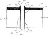
Чтобы обеспечить указанные выше преимущества, согласно одному аспекту настоящего изобретения предлагается первый способ для замещения, по меньшей мере, одной проводящей жидкий поток части элемента оборудования, имеющей участок крепления. Первый способ включает в себя обеспечение замещающей части, содержащей проводящий жидкий поток, первый участок, включающий в себя устойчивый к коррозии первый материал и проводящий жидкий поток, второй участок, включающий в себя второй материал, который идентичен или в основном идентичен материалу участка крепления. Первый участок и второй участок прямо и опосредованно соединяются твердой сваркой, образуя единую, проводящую жидкий поток, замещающую часть. Замещающая часть прикрепляется к элементу оборудования способом, содержащим прикрепление второго материла второго участка замещающей части к участку крепления элемента оборудования.In order to provide the above advantages, according to one aspect of the present invention, there is provided a first method for replacing at least one fluid conducting part of an item of equipment having an attachment portion. The first method includes providing a replacement part comprising a conductive fluid stream, a first portion including a corrosion resistant first material and a conductive fluid stream, a second portion including a second material that is identical or substantially identical to the material of the attachment portion. The first section and the second section are directly and indirectly connected by solid welding, forming a single, conductive liquid flow substituting part. The replacement part is attached to the equipment item in a manner comprising attaching the second material of the second portion of the replacement part to the equipment component attachment area.
В определенных неограничивающих вариантах осуществления первого способа замещающая часть выбирается из части цилиндрической формы, трубки, трубы, сопла, обрезанного конца, соединителя трубок, соединителя труб, трубки десорбера, трубки теплообменника и проводящей жидкий поток части.In certain non-limiting embodiments of the first method, the replacement part is selected from a cylindrical part, a tube, a pipe, a nozzle, a cut-off end, a pipe connector, a pipe connector, a stripper tube, a heat exchanger tube, and a liquid conducting part.
В определенных неограничивающих вариантах осуществления первого способа элемент оборудования представляет собой узел десорбера оборудования для синтеза мочевины, замещающая часть представляет собой трубку десорбера, и участок крепления представляет собой участок перегородки десорбера для крепления трубок.In certain non-limiting embodiments of the first method, the equipment item is a stripper assembly for urea synthesis equipment, the replacement part is a stripper tube, and the attachment portion is a portion of the stripper baffle for attaching the tubes.
В определенных неограничивающих вариантах осуществления первого способа замещающая часть прикрепляется к элементу оборудования способом, включающим в себя приварку второго материала второго участка замещающей части к участку крепления элемента оборудования. В определенных неограничивающих вариантах осуществления первого способа прикрепление второго материала второго участка к участку крепления осуществляется с использованием, например, технологии сварки, выбранной из автогенной сварки и сварки плавлением с использованием сварочного металла.In certain non-limiting embodiments of the first method, the replacement part is attached to the item of equipment by a method including welding the second material of the second portion of the replacement part to the attachment section of the item of equipment. In certain non-limiting embodiments of the first method, the second material is attached to the second portion to the attachment portion using, for example, welding technology selected from autogenous welding and fusion welding using weld metal.
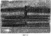
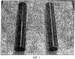
В определенных неограничивающих вариантах осуществления первого способа сварка в твердом состоянии первого участка прямо и опосредованно ко второму участку включает в себя технологию сварки в твердом состоянии, выбранную из холодной сварки, диффузионной сварки, сварки взрывом, кузнечной сварки, сварки трением, инерционной сварки, сварки горячим прессованием, сварки прокаткой и ультразвуковой сварки.In certain non-limiting embodiments of the first method, the solid state welding of the first section directly and indirectly to the second section includes a solid state welding technology selected from cold welding, diffusion welding, explosion welding, blacksmith welding, friction welding, inertia welding, hot welding pressing, welding by rolling and ultrasonic welding.
В определенных неограничивающих вариантах осуществления первого способа первый участок изготовлен из одного материала, и второй участок изготовлен из одного материала. В определенных неограничивающих вариантах осуществления первого способа, устойчивый к коррозии первый материал представляет собой, по меньшей мере, один материал, выбранный из циркония, сплавов циркония, титана, сплавов титана, ниобия и сплавов ниобия. В определенных неограничивающих вариантах осуществления первого способа второй материал выбирают из группы, состоящей из титана, сплавов титана и нержавеющей стали.In certain non-limiting embodiments of the first method, the first portion is made of one material and the second portion is made of one material. In certain non-limiting embodiments of the first method, the corrosion resistant first material is at least one material selected from zirconium, alloys of zirconium, titanium, alloys of titanium, niobium and alloys of niobium. In certain non-limiting embodiments of the first method, the second material is selected from the group consisting of titanium, titanium alloys, and stainless steel.
В определенных неограничивающих вариантах осуществления первого способа второй участок включает в себя внутренний слой из устойчивого к коррозии материала и внешний слой из второго материала. В определенных неограничивающих вариантах осуществления первого способа способ, содержащий сплавление внутреннего слоя и внешнего слоя, формирует данный второй участок. Один неограничивающий пример технологии, которая может быть использована для сплавления внутреннего и внешнего слоев, представляет собой соединение экструзией. В определенных неограничивающих вариантах осуществления первого способа металлургическое связывание внутреннего слоя и внешнего слоя второго участка образует данный второй участок. Такой способ металлургического связывания может включать в себя, например, выполнение, по меньшей мере, одной технологии металлургического связывания, выбранной из связывания экструзией, связывания взрывом, горячего изостатического прессования и центробежного литья. В определенных неограничивающих вариантах осуществления внутренний слой изготавливается из материала, выбранного из группы, состоящей из циркония и сплавов циркония, и внешний слой изготавливается из материала, выбранного из группы, состоящей из титана и сплавов титана.In certain non-limiting embodiments of the first method, the second portion includes an inner layer of a corrosion-resistant material and an outer layer of a second material. In certain non-limiting embodiments of the first method, a method comprising fusing the inner layer and the outer layer forms this second portion. One non-limiting example of a technology that can be used to fuse the inner and outer layers is extrusion bonding. In certain non-limiting embodiments of the first method, metallurgical bonding of the inner layer and the outer layer of the second portion forms this second portion. Such a metallurgical bonding method may include, for example, performing at least one metallurgical bonding technique selected from extrusion bonding, blast bonding, hot isostatic pressing and centrifugal casting. In certain non-limiting embodiments, the inner layer is made from a material selected from the group consisting of zirconium and zirconium alloys, and the outer layer is made from a material selected from the group consisting of titanium and titanium alloys.
Согласно еще одному неограничивающему варианту осуществления первого способа элемент оборудования представляет собой узел десорбера оборудования для синтеза мочевины, замещающая часть представляет собой трубку десорбера, участок крепления представляет собой участок перегородки для крепления трубок, первый участок замещающей части представляет собой цирконий, и второй участок замещающей части содержит внутренний слой из материала, выбранного из группы, состоящей из циркония и сплавов циркония, и внешний слой из материала, выбранного из группы, состоящей из титана и сплавов титана.According to yet another non-limiting embodiment of the first method, the equipment item is a urea synthesis equipment stripper assembly, the replacement portion is a stripper tube, the attachment portion is a baffle portion for tubing attachment, the first portion of the replacement portion is zirconium, and the second portion of the replacement portion contains an inner layer of a material selected from the group consisting of zirconium and zirconium alloys, and an outer layer of a material selected o from the group consisting of titanium and titanium alloys.
В определенных вариантах осуществления первого способа элемент оборудования представляет собой узел десорбера оборудования для синтеза мочевины; замещающая часть представляет собой трубку десорбера; участок крепления представляет собой участок перегородки для крепления трубок; первый участок замещающей части представляет собой цирконий; и второй участок замещающей части содержит внутренний слой из материала, выбранного из циркония и сплавов циркония, и внешний слой из материала, выбранного из титана и сплавов титана. В некоторых из указанных вариантов осуществления внутренний слой металлургически связан с внешним слоем посредством способа, который может включать в себя, например, по меньшей мере, одну технологию, выбранную из связывания экструзией, связывания взрывом, горячего изостатического прессования и центробежного литья. В некоторых из указанных вариантов осуществления участок сварки, образованный сваркой в твердом состоянии первого участка прямо или опосредованно со вторым участком, по существу, свободен от сплавов, объединяющих первый материал и второй материал. В вариантах осуществления, в которых первый участок представляет собой твердое тело, опосредованно приваренное ко второму участку, по меньшей мере, один третий материал может располагаться между первым участком и вторым участком. Такой, по меньшей мере, один третий материал может быть выбран из, например, титана, сплавов титана, ванадия, сплавов ванадия, тантала, сплавов тантала, гафния, сплавов гафния, ниобия и сплавов ниобия.In certain embodiments of the first method, the equipment item is a urea synthesis equipment stripper assembly; the replacement part is a stripper tube; the mounting portion is a portion of the partition for mounting the tubes; the first portion of the replacement part is zirconium; and the second portion of the replacement part comprises an inner layer of a material selected from zirconium and zirconium alloys, and an outer layer of a material selected from titanium and titanium alloys. In some of these embodiments, the inner layer is metallurgically bonded to the outer layer by a process that may include, for example, at least one technology selected from extrusion bonding, blast bonding, hot isostatic pressing, and centrifugal casting. In some of these embodiments, the weld portion formed by solid state welding of the first portion directly or indirectly with the second portion is substantially free of alloys combining the first material and the second material. In embodiments in which the first portion is a solid body indirectly welded to the second portion, at least one third material may be located between the first portion and the second portion. Such at least one third material may be selected from, for example, titanium, titanium alloys, vanadium alloys, vanadium alloys, tantalum alloys, tantalum alloys, hafnium alloys, hafnium alloys, niobium alloys and niobium alloys.
Согласно другому аспекту настоящего изобретения предлагается второй способ. Второй способ предназначен для замены трубки десорбера в узле десорбера для синтеза мочевины на замещающую трубку десорбера. Второй способ включает в себя предложение замещающей трубки десорбера, содержащей проводящий жидкий поток первый участок, включающий в себя устойчивый к коррозии первый материал, и проводящий жидкий поток второй участок, включающий в себя второй материал, который представляет собой материал, идентичный или в основном идентичный материалу, из которого сконструирована перегородка десорбера для крепления трубок. Первый участок и второй участок прямо или опосредованно соединяются сваркой в твердом состоянии, образуя единую, проводящую жидкий поток, замещающую часть. Чтобы присоединить замещающую трубку десорбера к десорберу, второй материал второго участка приваривается к идентичному или в основном идентичному материалу перегородки для крепления трубок. Такой способ сварки может быть, например, технологией сварки сплавлением, выбранной из автогенной сварки и сварки с использованием сварочного металла.According to another aspect of the present invention, a second method is provided. The second method is intended to replace the stripper tube in the urea synthesis stripper assembly with a replacement stripper tube. The second method includes providing a stripper replacement tube comprising a conductive fluid stream of a first portion including a corrosion resistant first material, and a conductive fluid flow of a second portion comprising a second material that is identical or substantially identical to the material from which the stripper baffle is designed for fastening the tubes. The first section and the second section are directly or indirectly connected by welding in a solid state, forming a single, conductive liquid stream, the replacement part. In order to attach the stripper replacement tube to the stripper, the second material of the second portion is welded to the identical or substantially identical baffle material for holding the tubes. Such a welding method may be, for example, fusion welding technology selected from autogenous welding and welding using welding metal.
В определенных неограничивающих вариантах осуществления второго способа устойчивый к коррозии первый материал представляет собой, по меньшей мере, один материал, выбранный из группы, состоящей из циркония и сплавов циркония. Неограничивающие примеры возможных сплавов циркония включают в себя Zr700 (UNS R60700), Zr702 (UNS R60702), Zr705 (UNS R60705) и Zircaloys. В определенных неограничивающих вариантах осуществления второго способа второй материал выбирают из группы, состоящей из титана и сплавов титана.In certain non-limiting embodiments of the second method, the corrosion resistant first material is at least one material selected from the group consisting of zirconium and zirconium alloys. Non-limiting examples of possible zirconium alloys include Zr700 (UNS R60700), Zr702 (UNS R60702), Zr705 (UNS R60705), and Zircaloys. In certain non-limiting embodiments of the second method, the second material is selected from the group consisting of titanium and titanium alloys.
В определенных неограничивающих вариантах осуществления второго способа сварка в твердом состоянии первого участка прямо или опосредованно со вторым участком осуществляется по технологии сварки в твердом состоянии, выбранной из холодной сварки, диффузионной сварки, сварки взрывом, кузнечной сварки, сварки трением, включая в себя инерционную сварку, сварки горячим прессованием, сварки прокаткой и ультразвуковой сварки. В определенных неограничивающих вариантах осуществления второго способа участок сварки, образованный сваркой в твердом состоянии первого участка прямо или опосредованно со вторым участком, по существу, свободен от сплавов устойчивого к коррозии первого материала и второго материала.In certain non-limiting embodiments of the second method, the solid state welding of the first section directly or indirectly with the second region is carried out according to the technology of solid state welding selected from cold welding, diffusion welding, explosion welding, blacksmith welding, friction welding, including inertia welding, hot pressing welding, rolling welding and ultrasonic welding. In certain non-limiting embodiments of the second method, the weld portion formed by solid state welding of the first portion directly or indirectly with the second portion is substantially free of alloys resistant to corrosion of the first material and the second material.
В определенных неограничивающих вариантах осуществления второго способа первый участок замещающей трубки десорбера изготовлен из одного материала, и второй участок изготовлен из одного материала. Альтернативно, в определенных вариантах осуществления второго способа второй участок содержит внутренний слой из устойчивого к коррозии материала и внешний слой из второго материала. В определенных вариантах осуществления альтернативного второго способа второй участок образуется связыванием экструзией так, что внутренний слой и внешний слой второго участка сплавляются. В определенных вариантах осуществления альтернативного второго способа второй участок содержит внутренний слой из материала, выбранного из циркония и сплавов циркония, и внешний участок из материала, выбранного из титана и сплавов титана.In certain non-limiting embodiments of the second method, the first portion of the stripper replacement tube is made of one material, and the second portion is made of one material. Alternatively, in certain embodiments of the second method, the second portion comprises an inner layer of a corrosion resistant material and an outer layer of a second material. In certain embodiments of the alternative second method, the second portion is formed by extrusion bonding so that the inner layer and the outer layer of the second portion are fused. In certain embodiments of the alternative second method, the second portion comprises an inner layer of a material selected from zirconium and zirconium alloys, and an outer portion of a material selected from titanium and titanium alloys.
В определенных неограничивающих вариантах осуществления второго способа первый участок опосредованно приварен в твердом состоянии ко второму участку, так что, по меньшей мере, один третий материал располагается между первым участком и вторым участком. Неограничивающие примеры данного, по меньшей мере, одного третьего материала, расположенного между первым участком и вторым участком, в таких неограничивающих вариантах осуществления включают в себя ванадий, сплавы ванадия, тантал, сплавы тантала, гафний, сплавы гафния, ниобий и сплавы ниобия.In certain non-limiting embodiments of the second method, the first portion is indirectly solid-welded to the second portion, so that at least one third material is located between the first portion and the second portion. Non-limiting examples of this at least one third material located between the first portion and the second portion, in such non-limiting embodiments, include vanadium, vanadium alloys, tantalum, tantalum alloys, hafnium, hafnium alloys, niobium and niobium alloys.
Согласно еще одному аспекту настоящего изобретения предлагается первая часть элемента оборудования. Данная первая часть включает в себя первый участок, проводящий жидкий поток, включающий в себя устойчивый к коррозии первый материал, и второй участок, проводящий жидкий поток, включающий в себя второй материал. Первый участок и второй участок прямо или опосредованно соединяются сваркой в твердом состоянии, образуя единую, проводящую жидкий поток часть. Первая часть может быть, например, замещающей частью или исходной частью элемента оборудования. Неограничивающие примеры возможных форм, в которых может обеспечиваться первая часть, включают в себя часть цилиндрической формы, трубку, трубу, сопло, обрезанный конец, соединитель трубок, соединитель, труб, трубку десорбера, трубку теплообменника и проводящую жидкий поток часть. Неограничивающие примеры элемента оборудования включают в себя химическое производственное оборудование, узел десорбера, узел конденсатора и теплообменник.According to another aspect of the present invention, a first part of an item of equipment is provided. This first part includes a first portion conducting a fluid stream including a corrosion resistant first material, and a second portion conducting a fluid stream including a second material. The first section and the second section are directly or indirectly connected by welding in a solid state, forming a single, conductive liquid flow part. The first part may be, for example, a replacement part or an initial part of an item of equipment. Non-limiting examples of possible shapes in which the first portion can be provided include a cylindrical portion, a tube, a pipe, a nozzle, a cut end, a pipe connector, a connector, pipes, a stripper tube, a heat exchanger tube, and a liquid conducting part. Non-limiting examples of an item of equipment include chemical manufacturing equipment, a stripper assembly, a condenser assembly, and a heat exchanger.
Неограничивающие примеры технологий сварки в твердом состоянии, которые могут быть использованы для прямой или опосредованной сварки в твердом состоянии первого участка со вторым участком первой части, включают в себя холодную сварку, диффузионную сварку, сварку взрывом, кузнечную сварку, сварку трением, инерционную сварку, сварку горячим прессованием, сварку прокаткой и ультразвуковую сварку. В определенных неограничивающих вариантах осуществления первой части устойчивый к коррозии первый материал представляет собой материал, выбранный из сплавов циркония, титана, сплавов титана, ниобия и сплавов ниобия. Неограничивающие примеры возможных сплавов циркония представляют собой Zr700 (UNS R60700), Zr702 (UNS R60702), Zr705 (UNS R60705) и Zircaloys (сорта циркония для ядерного применения). Также в определенных неограничивающих вариантах осуществления первой части второй материал выбирают из группы, состоящей из титана, сплавов титана и нержавеющей стали.Non-limiting examples of solid state welding technologies that can be used for direct or indirect solid state welding of the first section with the second section of the first part include cold welding, diffusion welding, explosion welding, blacksmith welding, friction welding, inertia welding, welding hot pressing, rolling welding and ultrasonic welding. In certain non-limiting embodiments of the first part, the corrosion resistant first material is a material selected from alloys of zirconium, titanium, alloys of titanium, niobium, and niobium alloys. Non-limiting examples of possible zirconium alloys are Zr700 (UNS R60700), Zr702 (UNS R60702), Zr705 (UNS R60705) and Zircaloys (zirconium grades for nuclear use). Also in certain non-limiting embodiments of the first part, the second material is selected from the group consisting of titanium, titanium alloys, and stainless steel.
В определенных неограничивающих вариантах осуществления первой части первый участок опосредованно приваривают в твердом состоянии ко второму участку так, что, по меньшей мере, один третий материал расположен между первым участком и вторым участком. Неограничивающие примеры данного, по меньшей мере, одного третьего материала, расположенного между первым участком и вторым участком, в таких неограничивающих вариантах осуществления включают в себя ванадий, сплавы ванадия, тантал, сплавы тантала, гафний, сплавы гафния, ниобий и сплавы ниобия.In certain non-limiting embodiments of the first part, the first portion is indirectly solid-welded to the second portion such that at least one third material is located between the first portion and the second portion. Non-limiting examples of this at least one third material located between the first portion and the second portion, in such non-limiting embodiments, include vanadium, vanadium alloys, tantalum, tantalum alloys, hafnium, hafnium alloys, niobium and niobium alloys.
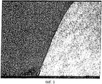
В определенных неограничивающих вариантах осуществления второй участок первой части включает в себя внутренний слой из устойчивого к коррозии материала и внешний слой из второго материала. В определенных неограничивающих вариантах осуществления второй участок первой части включает в себя внутренний слой из материала, выбранного из циркония и сплавов циркония, и внешний слой из материала, выбранного из титана и сплавов титана. Внутренний и внешний слои второго участка могут быть, например, прямо или опосредованно металлургически связаны вместе. В одном варианте осуществления внутренний и внешний слои прямо металлургически связаны с помощью способа, выбранного из связывания экструзией (соэкструзия), связывания взрывом, горячего изостатического прессования и центробежного литья. В определенных вариантах осуществления отсутствие какого-либо существенного междиффузионного слоя, образованного между прямо металлургически связанными внутренним и внешним слоями, позволяет элементу легко обрабатываться холодным способом во время процесса изготовления проводящей жидкий поток части.In certain non-limiting embodiments, the second portion of the first portion includes an inner layer of a corrosion resistant material and an outer layer of a second material. In certain non-limiting embodiments, the second portion of the first portion includes an inner layer of a material selected from zirconium and zirconium alloys, and an outer layer of a material selected from titanium and titanium alloys. The inner and outer layers of the second section can, for example, be directly or indirectly metallurgically bonded together. In one embodiment, the inner and outer layers are directly metallurgically bonded using a method selected from extrusion bonding (coextrusion), explosion bonding, hot isostatic pressing, and centrifugal casting. In certain embodiments, the absence of any substantial interdiffusion layer formed between the directly metallurgically bonded inner and outer layers allows the element to be easily cold worked during the manufacturing process of the fluid-conducting part.
Согласно дополнительному аспекту настоящего изобретения предлагается третий способ. Третий способ предназначен для замены трубки десорбера в десорбере узла синтеза мочевины на замещающую трубку десорбера. Третий способ включает в себя замену существующей трубки десорбера узла синтеза мочевины на устойчивую к коррозии трубку десорбера, имеющую конструкцию вышеописанной первой части.According to a further aspect of the present invention, a third method is provided. The third method is intended to replace the stripper tube in the stripper of the urea synthesis unit with a replacement stripper tube. The third method involves replacing the existing stripper tube of the urea synthesis unit with a corrosion resistant stripper tube having the structure of the first part described above.
Согласно другому аспекту настоящего изобретения предлагается первый элемент оборудования. Данный элемент оборудования включает в себя часть, имеющую конструкцию первой части. Согласно определенным неограничивающим вариантам осуществления первый элемент оборудования представляет собой элемент химического производственного оборудования, узел десорбера, узел конденсатора и теплообменник. Также согласно определенным, неограничивающим вариантам осуществления, первая часть, включенная в первый элемент оборудования, представляет собой часть, выбранную из части цилиндрической формы, трубки, трубы, сопла, обрезанного конца, соединителя трубок, соединителя труб, трубки десорбера, трубки теплообменника и проводящей жидкий поток части.According to another aspect of the present invention, a first item of equipment is provided. This item of equipment includes a part having the construction of the first part. According to certain non-limiting embodiments, the first equipment item is a chemical production equipment element, a stripper assembly, a condenser assembly, and a heat exchanger. Also, according to certain, non-limiting embodiments, the first part included in the first piece of equipment is a part selected from a cylindrical part, a tube, a pipe, a nozzle, a trimmed end, a pipe connector, a pipe connector, a stripper tube, a heat exchanger tube and a conductive liquid flow parts.
Согласно дополнительному аспекту настоящего изобретения обеспечивается четвертый способ. Четвертый способ предназначен для приготовления проводящей жидкий поток части, содержащей внутренний слой из устойчивого к коррозии материала, окружающий проводящий жидкий поток проход, и внешний слой из другого материала. В определенных вариантах осуществления четвертого способа проводящая жидкий поток часть образуется из элемента, включающего первый слой циркония или сплава циркония, который прямо металлургически связан со слоем титана или сплава титана, и в котором нет существенного диффузионного промежуточного слоя между связанными первым и вторым слоями.According to a further aspect of the present invention, a fourth method is provided. A fourth method is for preparing a fluid conducting part containing an inner layer of a corrosion resistant material, a passage surrounding the fluid conducting stream, and an outer layer of another material. In certain embodiments of the fourth method, the fluid conducting part is formed from an element comprising a first layer of zirconium or a zirconium alloy that is directly metallurgically bonded to a titanium or titanium alloy layer and in which there is no significant diffusion intermediate layer between the bound first and second layers.
Согласно другому аспекту настоящего изобретения предлагается пятый способ. Пятый способ предназначен для замены, по меньшей мере, одной проводящей жидкий поток части элемента оборудования, имеющего участок крепления. Пятый способ включает в себя обеспечение замены проводящей жидкий поток части, содержащей внутренний слой из устойчивого к коррозии первого материала, окружающий проводящий жидкий поток проход сквозь данную проводящую жидкий поток часть, и внешний слой из второго материала. Внутренний слой представляет собой слой, прямо или опосредованно металлургически связанный с внешним слоем. Неограничивающие примеры технологий, которые могут быть использованы, чтобы прямо или опосредованно металлургически связывать слои в пятом способе, включают в себя связывание экструзией, связывание взрывом, горячее изостатическое прессование и центробежное литье.According to another aspect of the present invention, a fifth method is provided. The fifth method is intended to replace at least one fluid-conducting part of an equipment item having a mounting portion. A fifth method includes providing a replacement for the fluid conducting part comprising an inner layer of a corrosion resistant first material, a surrounding fluid conducting passage through a given fluid conducting part, and an outer layer of a second material. The inner layer is a layer directly or indirectly metallurgically bonded to the outer layer. Non-limiting examples of technologies that can be used to directly or indirectly metallurgically bond the layers in the fifth method include extrusion bonding, blast bonding, hot isostatic pressing and centrifugal casting.
В определенных неограничивающих вариантах осуществления пятого способа замещающая часть прикрепляется к элементу оборудования посредством способа, содержащего крепление внешнего слоя замещающей части к участку крепления элемента оборудования. Неограничивающие примеры способов, пригодных для крепления внешнего слоя к участку крепления в пятом способе, включают в себя сварку, сварку плавлением, автогенную сварку и сварку плавлением с применением присадочного металла. В определенных неограничивающих вариантах осуществления пятого способа участок крепления включает в себя третий материал, который представляет собой материал, идентичный или в основном идентичный второму материалу замещающей части, и крепление замещающей части к элементу оборудования включает в себя крепление участка внешнего слоя к третьему материалу участка крепления.In certain non-limiting embodiments of the fifth method, the replacement part is attached to an item of equipment by a method comprising attaching an outer layer of the replacement part to an attachment portion of an item of equipment. Non-limiting examples of methods suitable for attaching the outer layer to the attachment site in the fifth method include welding, fusion welding, autogenous welding and fusion welding using filler metal. In certain non-limiting embodiments of the fifth method, the attachment portion includes a third material that is identical or substantially identical to the second material of the replacement portion, and attaching the replacement portion to an item of equipment includes attaching a portion of the outer layer to the third material of the attachment portion.
Проводящая жидкий поток часть упомянутого пятого способа может быть выбрана из, например, части цилиндрической формы, трубки, трубки десорбера, трубки теплообменника, трубы и сопла. Также в определенных неограничивающих вариантах осуществления пятого способа устойчивый к коррозии первый материал выбирают из циркония и сплавов циркония (таких как, например, Zr700 (UNS R60700), Zr702 (UNS R60702), Zr705 (UNS R60705) и Zircaloys). Также в определенных неограничивающих вариантах осуществления пятого способа второй материал выбирают из группы, состоящей из титана и сплавов титана.The liquid conducting part of said fifth method may be selected from, for example, a cylindrical part, a tube, a stripper tube, a heat exchanger tube, a pipe, and a nozzle. Also in certain non-limiting embodiments of the fifth method, the corrosion resistant first material is selected from zirconium and zirconium alloys (such as, for example, Zr700 (UNS R60700), Zr702 (UNS R60702), Zr705 (UNS R60705) and Zircaloys). Also, in certain non-limiting embodiments of the fifth method, the second material is selected from the group consisting of titanium and titanium alloys.
В определенных неограничивающих вариантах осуществления пятого способа внутренний слой и внешний слой представляют собой слои, прямо или опосредованно металлургически связанные посредством способа, включающего, по меньшей мере, одну технологию, выбранную из группы, состоящей из связывания экструзией, связывания взрывом, горячего изостатического прессования и центробежного литья. Также в определенных неограничивающих вариантах осуществления пятого способа не возникает никакого существенного междиффузионного слоя во время прямого или опосредованного металлургического связывания внутреннего и внешнего слоев. В таком случае полученная часть может легко подвергаться холодной обработке, такой как использование холодного волочения или холодного обжатия трубок.In certain non-limiting embodiments of the fifth method, the inner layer and the outer layer are layers directly or indirectly metallurgically bonded by a method comprising at least one technology selected from the group consisting of extrusion bonding, explosion bonding, hot isostatic pressing and centrifugal casting. Also, in certain non-limiting embodiments of the fifth method, no significant interdiffusion layer occurs during direct or indirect metallurgical bonding of the inner and outer layers. In this case, the obtained part can easily be cold worked, such as using cold drawing or cold crimping of the tubes.
В определенных неограничивающих вариантах осуществления упомянутого пятого способа элемент оборудования представляет собой узел десорбера оборудования для синтеза мочевины, замещающая часть представляет собой трубку десорбера, и участок крепления представляет собой участок перегородки для крепления трубок. Также в определенных неограничивающих вариантах осуществления пятого способа элемент оборудования представляет собой узел десорбера оборудования для синтеза мочевины; замещающая часть представляет собой трубку десорбера; участок крепления представляет собой участок перегородки для крепления трубок; внутренний слой замещающей части выбирают из циркония и сплавов циркония; и внешний слой замещения выбирают из титана и сплавов титана.In certain non-limiting embodiments of said fifth method, the equipment item is a urea synthesis equipment stripper assembly, the replacement portion is a stripper tube, and the attachment portion is a portion of the baffle for attachment of the tubes. Also, in certain non-limiting embodiments of the fifth method, the equipment item is a urea synthesis equipment stripper assembly; the replacement part is a stripper tube; the mounting portion is a portion of the partition for mounting the tubes; the inner layer of the replacement part is selected from zirconium and zirconium alloys; and the outer substitution layer is selected from titanium and titanium alloys.
В определенных неограничивающих вариантах осуществления пятого способа крепление замещающей части к элементу оборудования включает в себя сварку плавлением участка второго материала внешнего слоя к третьему материалу участка крепления, так что образованный участок сварки существенно свободен от сплавов, имеющих, по существу, пониженную устойчивость к коррозии относительно первого материала и второго материала.In certain non-limiting embodiments of the fifth method, attaching the replacement part to an item of equipment includes fusion welding of a portion of the second material of the outer layer to the third material of the attachment portion, such that the formed welding portion is substantially free of alloys having substantially reduced corrosion resistance relative to the first material and a second material.
В определенных неограничивающих вариантах осуществления пятого способа внутренний слой прямо металлургически связан с внешним слоем. В определенных неограничивающих вариантах осуществления пятого способа внутренний слой опосредованно металлургически связан с внешним слоем, так что, по меньшей мере, один слой, содержащий третий материал, который отличается от первого материала и второго материала, расположен между внутренним слоем и внешним слоем.In certain non-limiting embodiments of the fifth method, the inner layer is directly metallurgically bonded to the outer layer. In certain non-limiting embodiments of the fifth method, the inner layer is indirectly metallurgically bonded to the outer layer, such that at least one layer containing a third material that is different from the first material and the second material is located between the inner layer and the outer layer.
Согласно еще одному дополнительному аспекту настоящего изобретения предлагается шестой способ. Шестой способ предназначен для замены трубки десорбера в десорбере узла синтеза мочевины на замещающую трубку десорбера. Шестой способ включает в себя обеспечение замещающей трубки десорбера, включающей в себя внутренний слой из устойчивого к коррозии первого материала, окружающий проводящий жидкий поток проход сквозь трубку десорбера, и внешний слой из второго материала, в котором внутренний слой прямо или опосредованно металлургически связан с внешним слоем и в котором второй материал идентичен или существенно идентичен материалу, из которого изготовлена перегородка десорбера для крепления трубок. Второй материал внешнего слоя крепится к идентичному или существенно идентичному материалу перегородки для крепления трубок.According to a still further aspect of the present invention, a sixth method is provided. The sixth method is intended to replace the stripper tube in the stripper of the urea synthesis unit with a replacement stripper tube. A sixth method includes providing a stripper replacement tube including an inner layer of a corrosion resistant first material surrounding a fluid conducting passage through the stripper tube, and an outer layer of a second material in which the inner layer is directly or indirectly metallurgically bonded to the outer layer and in which the second material is identical or substantially identical to the material of which the stripper baffle is made to hold the tubes. The second material of the outer layer is attached to the identical or substantially identical material of the partition wall for fastening the tubes.
В определенных неограничивающих вариантах осуществления шестого способа устойчивый к коррозии первый материал представляет собой, по меньшей мере, один материал, выбранный из циркония и сплавов циркония (таких как, например, Zr700 (UNS R60700), Zr702 (UNS R60702), Zr705 (UNS R60705) и Zircaloys). В определенных неограничивающих вариантах осуществления шестого способа второй материал выбирают из титана и сплавов титана.In certain non-limiting embodiments of the sixth method, the corrosion resistant first material is at least one selected from zirconium and zirconium alloys (such as, for example, Zr700 (UNS R60700), Zr702 (UNS R60702), Zr705 (UNS R60705 ) and Zircaloys). In certain non-limiting embodiments of the sixth method, the second material is selected from titanium and titanium alloys.
Согласно определенным неограничивающим вариантам осуществления шестого способа крепление второго материала внешнего слоя к идентичному или, по существу, идентичному материалу перегородки для крепления трубок содержит сварку второго материала внешнего слоя с по существу идентичным материалом перегородки для крепления трубок. Неограничивающие примеры технологий сварки, которые могут быть использованы, включают в себя автогенную сварку и сварку плавлением с использованием сварочного металла. В определенных вариантах осуществления шестого способа участок сварки, образованный сваркой второго материала внешнего слоя с идентичным или по существу идентичным материалом перегородки для крепления трубок, по существу, свободен от сплавов, имеющих значительно пониженную устойчивость к коррозии относительно второго материала.According to certain non-limiting embodiments of the sixth method, attaching the second material of the outer layer to the identical or substantially identical material of the baffle for fastening the tubes comprises welding the second material of the outer layer with a substantially identical material of the baffle for fastening the tubes. Non-limiting examples of welding technologies that can be used include autogenous welding and fusion welding using weld metal. In certain embodiments of the sixth method, the weld portion formed by welding the second material of the outer layer with identical or substantially identical baffle material for fastening the tubes is substantially free of alloys having significantly reduced corrosion resistance with respect to the second material.
В определенных неограничивающих вариантах осуществления шестого способа внутренний слой и внешний слой трубки десорбера прямо или опосредованно металлургически связаны посредством способа, включающего в себя, по меньшей мере, одну технологию, выбранную из связывания экструзией, связывания взрывом, горячего изостатического прессования и центробежного литья. Также в определенных неограничивающих вариантах осуществления шестого способа внутренний слой прямо металлургически связан с внешним слоем и в определенных вариантах осуществления не возникает, по существу, междиффузионного слоя, когда внутренний слой металлургически связывается с внешним слоем. В других определенных неограничивающих вариантах осуществления шестого способа внутренний слой опосредованно металлургически связан с внешним слоем, так что, по меньшей мере, один слой, содержащий материал, который отличается от первого материала и второго материала, расположен между внутренним слоем и внешним слоем.In certain non-limiting embodiments of the sixth method, the inner layer and the outer layer of the stripper tube are directly or indirectly metallurgically bonded by a method including at least one technology selected from extrusion bonding, explosion bonding, hot isostatic pressing and centrifugal casting. Also, in certain non-limiting embodiments of the sixth method, the inner layer is directly metallurgically bonded to the outer layer and in certain embodiments, essentially no interdiffusion layer occurs when the inner layer is metallurgically bonded to the outer layer. In other specific non-limiting embodiments of the sixth method, the inner layer is indirectly metallurgically bonded to the outer layer, so that at least one layer containing a material that is different from the first material and the second material is located between the inner layer and the outer layer.
Согласно еще одному дополнительному аспекту настоящего изобретения предлагается вторая часть элемента оборудования. Вторая часть выбирается из трубки десорбера и трубки теплообменника и включает в себя внутренний слой из устойчивого к коррозии первого материала, окружающий проводящий жидкий поток проход через проводящую жидкий поток часть, и внешний слой из второго материала, и при этом внутренний слой прямо или опосредованно металлургически связан с внешним слоем. Вторая часть может быть замещающей частью или исходной частью элемента оборудования. В случае когда вторая часть представляет собой трубку десорбера, элемент оборудования может быть, например, узлом десорбера оборудования для синтеза мочевины.According to another additional aspect of the present invention, a second part of an item of equipment is provided. The second part is selected from the stripper tube and the heat exchanger tube and includes an inner layer of a corrosion-resistant first material, a passage surrounding the liquid-conducting passage through the liquid-conducting part, and an outer layer of the second material, and the inner layer is directly or indirectly metallurgically bonded with the outer layer. The second part may be a replacement part or an initial part of an item of equipment. In the case where the second part is a stripper tube, the item of equipment may be, for example, a stripper assembly of urea synthesis equipment.
Как описано, во второй части внутренний слой прямо или опосредованно металлургически связан с внешним слоем. Неограничивающие примеры технологий, которые могут быть использованы, чтобы прямо или опосредованно металлургически связывать слои, включают в себя связывание экструзией, связывание взрывом, горячее изостатическое прессование и центробежное литье.As described, in the second part, the inner layer is directly or indirectly metallurgically bonded to the outer layer. Non-limiting examples of technologies that can be used to directly or indirectly metallurgically bond layers include extrusion bonding, explosion bonding, hot isostatic pressing, and centrifugal casting.
В определенных неограничивающих вариантах осуществления второй части внутренний слой второй части прямо металлургически связан с внешним слоем. В некоторых из таких вариантов осуществления не возникает, по существу, междиффузионного слоя между прямо металлургически связанными внутренним и внешним слоями, что позволяет полученной части легко подвергаться холодной обработке, такой как, например, холодное волочение или холодное обжатие трубок. В других неограничивающих вариантах осуществления второй части внутренний слой опосредованно металлургически связан с внешним слоем, так что, по меньшей мере, один слой, включающий в себя третий материал, который отличается от первого материала и второго материала, располагается между внутренним слоем и внешним слоем.In certain non-limiting embodiments of the second part, the inner layer of the second part is directly metallurgically bonded to the outer layer. In some of these embodiments, essentially no interdiffusion layer arises between the directly metallurgically bonded inner and outer layers, which allows the resulting part to be easily cold worked, such as, for example, cold drawing or cold crimping tubes. In other non-limiting embodiments of the second part, the inner layer is indirectly metallurgically bonded to the outer layer, so that at least one layer including a third material, which is different from the first material and the second material, is located between the inner layer and the outer layer.
Согласно другому аспекту настоящего изобретения предлагается седьмой способ. Седьмой способ предназначен для изготовления проводящей жидкий поток части, содержащей внутренний слой из устойчивого к коррозии первого материала, окружающий проводящий жидкий поток проход, и внешний слой из второго материала. Седьмой способ включает в себя металлургическое связывание внутреннего слоя и внешнего слоя без образования какого-либо существенного междиффузионного слоя между внутренним слоем и внешним слоем.According to another aspect of the present invention, a seventh method is provided. The seventh method is for the manufacture of a liquid conducting part comprising an inner layer of a corrosion resistant first material, a surrounding liquid conducting passage, and an outer layer of a second material. The seventh method involves metallurgical bonding of the inner layer and the outer layer without the formation of any significant interdiffusion layer between the inner layer and the outer layer.
В определенных вариантах осуществления седьмого способа часть, получаемая путем металлургического связывания внутреннего слоя и внешнего слоя, может легко подвергаться холодной обработке, и в таких случаях данный способ может дополнительно включать в себя холодную обработку промежуточной части. Неограничивающие примеры возможных технологий, которые могут быть использованы для холодной обработки данной части, включают в себя холодное волочение, холодное обжатие трубок, трубопрокатку с внутренними и внешними валками и поточное формирование.In certain embodiments of the seventh method, the part obtained by metallurgical bonding of the inner layer and the outer layer can easily be cold worked, and in such cases, the method may further include cold work of the intermediate part. Non-limiting examples of possible technologies that can be used for cold processing of this part include cold drawing, cold crimping of tubes, tube rolling with internal and external rolls, and in-line formation.
В определенных неограничивающих вариантах осуществления седьмого способа устойчивый к коррозии первый материал представляет собой, по меньшей мере, один материал, выбранный из группы, состоящей из циркония и сплавов циркония (таких как, например, Zr700 (UNS R607.00), Zr702 (UNS R60702), Zr705 (UNS R60705) и Zircaloys). Также в определенных вариантах осуществления седьмого способа второй материал выбирается из титана и сплавов титана.In certain non-limiting embodiments of the seventh method, the corrosion resistant first material is at least one material selected from the group consisting of zirconium and zirconium alloys (such as, for example, Zr700 (UNS R607.00), Zr702 (UNS R60702 ), Zr705 (UNS R60705) and Zircaloys). Also, in certain embodiments of the seventh method, the second material is selected from titanium and titanium alloys.
Согласно другому дополнительному аспекту настоящего изобретения предлагается восьмой способ. Восьмой способ предназначен для замены трубки десорбера в десорбере узла синтеза мочевины на замещающую трубку десорбера. Восьмой способ включает в себя замену существующей трубки десорбера узла синтеза мочевины на устойчивую к коррозии трубку десорбера, имеющую конструкцию второй части.According to another further aspect of the present invention, an eighth method is provided. The eighth method is intended to replace the stripper tube in the stripper of the urea synthesis unit with a replacement stripper tube. The eighth method involves replacing the existing urea synthesis unit stripper tube with a corrosion resistant stripper tube having a second part structure.
Согласно дополнительному аспекту настоящего изобретения предлагается элемент оборудования, при этом элемент оборудования включает в себя вторую часть. Возможные неограничивающие примеры элемента оборудования включают в себя химическое производственное оборудование, узел десорбера, узел конденсатора и теплообменник.According to a further aspect of the present invention, an equipment item is provided, wherein the equipment item includes a second part. Possible non-limiting examples of an item of equipment include chemical manufacturing equipment, a stripper assembly, a condenser assembly, and a heat exchanger.
Предпочтительно уменьшение чужеродных загрязнений на, по меньшей мере, одной из внешней поверхности первого цилиндра и внутренней поверхности второго цилиндра содержит чистку, по меньшей мере, одной из внешней поверхности первого цилиндра и внутренней поверхности второго цилиндра с использованием способов очистки, при которых остатки очищающих агентов не остаются на очищаемой поверхности.Preferably, the reduction of foreign contaminants on at least one of the outer surface of the first cylinder and the inner surface of the second cylinder comprises cleaning at least one of the outer surface of the first cylinder and the inner surface of the second cylinder using cleaning methods in which residues of cleaning agents are not remain on the surface being cleaned.
Предпочтительно ледяная продувка включает в себя движение кристаллической воды против поверхности, таким образом механически очищая и промывая жидкостью поверхность.Preferably, ice blowing involves moving crystalline water against the surface, thereby mechanically cleaning and flushing the surface with liquid.
Читатель примет во внимание упомянутые детали и преимущества, а также и другие, при рассмотрении последующего подробного описания определенных неограничивающих вариантов осуществления данных способов, элементов и частей настоящего изобретения. Читатель может также понять определенные дополнительные преимущества и подробности осуществления или использования описанных здесь способов, элементов и частей.The reader will take into account the mentioned details and advantages, as well as others, when considering the subsequent detailed description of certain non-limiting embodiments of these methods, elements and parts of the present invention. The reader may also understand certain additional advantages and details of the implementation or use of the methods, elements and parts described herein.
КРАТКОЕ ОПИСАНИЕ ЧЕРТЕЖЕЙBRIEF DESCRIPTION OF THE DRAWINGS
Признаки и преимущества данных способов могут быть лучше поняты со ссылкой на сопровождающие чертежи.The features and advantages of these methods can be better understood with reference to the accompanying drawings.
Фиг.1 иллюстрирует один вариант осуществления трубки десорбера по настоящему изобретению, в котором трубка включает в себя первый проводящий жидкий поток участок, изготовленный из циркония и присоединенный технологией инерционной сварки или другой сварки в твердом состоянии ко второму проводящему жидкий поток участку, изготовленному из титана.Figure 1 illustrates one embodiment of the stripper tube of the present invention, in which the tube includes a first conductive liquid flow section made of zirconium and joined by inertia welding or other solid state welding technology to a second liquid conductive section made of titanium.
Фиг.2 иллюстрирует расположение для крепления трубки десорбера фиг.1 к плакированной титаном поверхности перегородки для крепления трубок десорбера, которая включает в себя использование многослойного, проводящего жидкий поток обрезка трубы.FIG. 2 illustrates an arrangement for attaching the stripper tube of FIG. 1 to a titanium-clad surface of a baffle for attaching the stripper tubes, which includes the use of a multilayer, fluid-conducting, trimming pipe.
Фиг.3 схематически иллюстрирует вариант осуществления способа изготовления многослойной, проводящей жидкий поток части.Figure 3 schematically illustrates an embodiment of a method for manufacturing a multilayer, fluid-conducting part.
Фиг.4 схематически иллюстрирует конец сваренной двухслойной заготовки, изготовленной в качестве промежуточного элемента в способе фиг.3.Figure 4 schematically illustrates the end of a welded two-layer billet made as an intermediate element in the method of figure 3.
Фиг.5 иллюстрирует расположение для крепления варианта осуществления трубки десорбера, включающей в себя многослойный конец трубы по настоящему изобретению, к плакированной титаном поверхности перегородки для крепления трубок десорбера.FIG. 5 illustrates an arrangement for attaching an embodiment of a stripper tube including a multilayer end of a pipe of the present invention to a titanium-clad surface of a baffle for securing stripper tubes.
Фиг.6 изображает неразрезанный и разрезанный образцы секции циркониевой трубки, которая была сварена инерционной сваркой с секцией титановой трубки.6 depicts uncut and cut samples of a section of a zirconium tube, which was welded by inertia welding with a section of a titanium tube.
Фиг.7 изображает два образца секции циркониевой трубки, сваренной инерционной сваркой с секцией титановой трубки, и в которой полученная цирконий/титановая проводящая жидкий поток трубка была обработана для удаления ребер.7 depicts two samples of a section of a zirconium tube welded by inertia welding with a section of a titanium tube, and in which the obtained zirconium / titanium conductive liquid flow tube was processed to remove fins.
Фиг.8 представляет собой фотографию сечения поверхности раздела сварного шва циркония с титаном в стенке трубки сваренного инерцией образца.Fig. 8 is a photograph of a cross section of the interface of a zirconium weld with titanium in the wall of a tube of an inertia-welded sample.
Фиг.9 представляет собой вид с большим увеличением поверхности раздела сварного шва, показанного на фиг.8.Fig.9 is a view with a large increase in the interface of the weld shown in Fig.8.
Фиг.10 представляет собой изображение с большим увеличением части участка поверхности раздела сварного шва, показанного на фиг.9.Figure 10 is an image with a large increase in part of the portion of the interface surface of the weld shown in Fig.9.
Фиг.11 и 12 представляют собой схематические изображения этапов варианта осуществления способа по настоящему изобретению для изготовления многослойной, проводящей жидкий поток части или части секции.11 and 12 are schematic diagrams of the steps of an embodiment of the method of the present invention for manufacturing a multilayer, liquid-conducting part or part of a section.
Фиг.13 иллюстрирует вид с конца сваренной двухслойной заготовки, изготовленной в качестве промежуточного элемента в одном из этапов способа, включенного в фиг.12.Fig.13 illustrates a view from the end of a welded two-layer billet made as an intermediate element in one of the stages of the method included in Fig.12.
Фиг.14 представляет собой микрофотографию металлургически связанного участка термообработанной многослойной трубки, изготовленной по варианту осуществления способа по настоящему изобретению.Fig. 14 is a micrograph of a metallurgically bonded portion of a heat-treated multilayer tube made in accordance with an embodiment of the method of the present invention.
ПОДРОБНОЕ ОПИСАНИЕ ОПРЕДЕЛЕННЫХ ВАРИАНТОВ ОСУЩЕСТВЛЕНИЯDETAILED DESCRIPTION OF THE SPECIFIC EMBODIMENTS
Определенные варианты осуществления, предлагаемые в настоящем изобретении, включают в себя новые, устойчивые к коррозии, проводящие жидкий поток части, оборудование, включающее в себя одну или больше таких частей, и способы замены проводящих жидкий поток частей оборудования, подвергнутого коррелирующим и/или эродирующим условиям, на устойчивые к коррозии, проводящие жидкий поток, замещающие части. Неограничивающие варианты осуществления новых частей включают в себя, например, части, имеющие цилиндрическую или другую форму, трубки, трубы, сопла, обрезанные концы, соединители трубок, соединители труб и другие проводящие жидкий поток части. Определенные неограничивающие варианты осуществления проводящих жидкий поток частей включают в себя, по меньшей мере, один первый проводящий жидкий поток участок, изготовленный из, по меньшей мере, одного устойчивого к коррозии материала, такого как, например, цирконий, титан, тантал, ниобий, сплавы любого из указанных металлов или другого устойчивого к коррозии металла или сплава. Данные части также включают в себя, по меньшей мере, один второй проводящий жидкий поток участок, включающий в себя материал, который композиционно идентичен или композиционно по существу идентичен материалу, из которого образован существующий участок крепления оборудования, к которому данная часть должна прикрепляться. Устойчивый к коррозии первый участок прямо или опосредованно соединен со вторым участком сваркой в твердом состоянии с образованием единой проводящей жидкий поток части, такой как, например, трубка или труба. Такая часть может прикрепляться к элементу оборудования сваркой с подобными материалами второго участка и части крепления оборудования. Подобные материалы могут свариваться плавлением, например, автогенной сваркой или использованием сварки со сварочным металлом, без возникновения условий в окрестности сварки плавлением, которые будут существенно способствовать коррозии.Certain embodiments of the present invention include new, corrosion resistant, fluid conducting parts, equipment including one or more such parts, and methods for replacing fluid conducting parts of equipment subjected to correlative and / or eroding conditions , resistant to corrosion, conductive liquid flow, replacement parts. Non-limiting embodiments of the new parts include, for example, parts having a cylindrical or other shape, tubes, pipes, nozzles, cut ends, pipe connectors, pipe connectors, and other liquid conducting parts. Certain non-limiting embodiments of the fluid conducting parts include at least one first fluid conducting portion made from at least one corrosion resistant material, such as, for example, zirconium, titanium, tantalum, niobium, alloys any of these metals or other corrosion resistant metal or alloy. These parts also include at least one second fluid conducting portion comprising a material that is compositionally identical or compositionally substantially identical to the material from which the existing equipment attachment portion to which the part is to be attached is formed. The corrosion resistant first section is directly or indirectly connected to the second section by solid state welding to form a single fluid conducting part, such as, for example, a tube or pipe. Such a part may be attached to the equipment element by welding with similar materials of the second section and the equipment mounting part. Such materials can be welded by fusion, for example, by autogenous welding or by welding with welding metal, without the occurrence of conditions in the vicinity of fusion welding, which will significantly contribute to corrosion.
Части и способы, описанные в настоящем изобретении, могут быть адаптированы для использования с различными типами химического производственного и другого оборудования. Неограничивающие варианты осуществления такого оборудования и особых проводящих жидкий поток частей такого оборудования, которые могут быть сконструированы по настоящему изобретению, включают в себя трубки для десорберов мочевины, конденсаторы карбамата и биметаллические десорберы, и трубки теплообменников, и трубы для химических и нефтехимических процессов.Parts and methods described in the present invention can be adapted for use with various types of chemical manufacturing and other equipment. Non-limiting embodiments of such equipment and specific fluid-conducting parts of such equipment that can be constructed according to the present invention include tubes for urea strippers, carbamate condensers and bimetal strippers, and heat exchanger tubes, and pipes for chemical and petrochemical processes.
Особый неограничивающий описанный здесь вариант осуществления представляет собой способ замены коррелированных и/или эродированных титановых трубок десорбера в оборудовании синтеза мочевины на замещающие трубки, содержащие участок устойчивого к коррозии металла или сплава, такого как участок циркония или сплава циркония, который был бы очень устойчивым к эффектам коррозии/эрозии среды процесса синтеза мочевины в трубках. Данный способ позволяет повторно использовать существующие плакированные титаном перегородки для крепления трубок десорбера и головки обменника, так что нет необходимости заменять весь узел десорбера. Данный способ включает в себя обеспечение замещающих трубок десорбера, имеющих (i) трубчатый, устойчивый к коррозии участок, изготовленный из, например, циркония или устойчивого к коррозии сплава циркония, и (ii), по меньшей мере, один трубчатый участок крепления, изготовленный из, например, титана или другого металла или сплава, который может свариваться плавлением с плакированной титаном перегородкой для крепления трубок десорбера без возникновения условий в окрестностях сварки плавлением, которые существенно способствуют коррозии или эрозии. Устойчивый к коррозии участок и участок крепления соединяются прямо или опосредованно технологией сварки в твердом состоянии с образованием проводящей жидкий поток замещающей части.A particular non-limiting embodiment described herein is a method of replacing correlated and / or eroded titanium stripper tubes in urea synthesis equipment with replacement tubes containing a section of a corrosion-resistant metal or alloy, such as a section of zirconium or a zirconium alloy, which would be very resistant to effects corrosion / erosion of the urea synthesis process in the tubes. This method allows you to reuse existing titanium clad partitions for mounting stripper tubes and exchanger heads, so that there is no need to replace the entire stripper assembly. This method includes providing replacement stripper tubes having (i) a tubular, corrosion resistant section made of, for example, zirconium or a corrosion resistant zirconium alloy, and (ii) at least one tubular mounting section made of for example, titanium or another metal or alloy that can be fused with a titanium-clad baffle to fasten stripper tubes without the occurrence of conditions in the vicinity of fusion welding that significantly contribute to corrosion or Rosii. The corrosion-resistant section and the fastening section are connected directly or indirectly by solid-state welding technology to form a fluid-conducting replacement part.
Фиг.1 представляет собой вид в разрезе одного неограничивающего варианта осуществления трубки 10 десорбера, сконструированной по настоящему изобретению. Трубка 10, например, может быть предложена как исходная часть узла десорбера или, как описано выше, может использоваться как замещающая трубка десорбера для модифицирования существующего узла десорбера. Трубка 10 десорбера включает в себя цилиндрический проход 12, определяемый непрерывной стенкой 13. Центральная часть непрерывной стенки 13 трубки 10 представляет собой устойчивую к коррозии циркониевую трубку 14. Некоторая длина титановой трубки 16 приварена инерционной сваркой на каждом конце циркониевой трубки 14. Концы титановой трубки 16 могут быть приварены плавлением к существующей плакированной титаном перегородке для крепления трубок в узле десорбера, не создавая разнородный сварной шов плавления цирконий-титан. Фиг.2 показывает одно возможное расположение сварки трубка-перегородка для крепления трубок, чтобы закрепить трубку 10 десорбера в трубном отверстии в перегородке 20 для крепления трубок. Понятно, что конфигурация крепления, показанная на фиг.2, может использоваться при исходном изготовлении десорбера или может использоваться при замене трубок десорбера в существующем десорбере, то есть при обслуживании. Трубка 10, которая включает в себя кусок титановой трубки 16, приваренный инерционной сваркой на участке 17 к участку 14 циркониевой трубки, располагается в отверстии плакированной титаном пластины 24 перегородки 20 для крепления трубок. Участки 26 представляют собой участки из углеродистой стали или нержавеющей стали перегородки 20 для крепления трубок. Трубка 10 крепится к перегородке 20 для крепления трубок прочным титановым сварным швом 28 при соединении отрезка титановой трубки 16 и плакированной титаном пластины 24. Таким образом, участок сварки плавлением полностью представляет собой титан, и в участке сварки плавлением не возникает сплавов, объединяющих титан и цирконий.Figure 1 is a sectional view of one non-limiting embodiment of a
Как обсуждается ниже, считается, что сплавы, образующиеся в участке сварки, когда сваривают плавлением несхожие металлы, такие как сплавы цирконий-титан, образующиеся, когда сваривают плавлением цирконий и титан, имеют склонность к коррозии, когда подвергаются коррелирующим веществам и/или условиям. Сварка в твердом состоянии, однако, не генерирует сплавы в каких-либо существенных количествах. Соответственно, обеспечивая проводящие жидкий поток части, имеющие высокоустойчивый к коррозии участок, приваренный в твердом состоянии к участку, включающему в себя материал, который идентичен части крепления оборудования или который иным образом не дает сплавов, склонных к коррозии, когда приваривается плавлением к части крепления, настоящий способ позволяет изготавливать или модифицировать оборудование с устойчивыми к коррозии частями, не вызывая условий, способствующих коррозии.As discussed below, it is believed that alloys formed in a weld area when dissimilar metals are welded by fusion, such as zirconium-titanium alloys formed when zirconium and titanium are welded by melting, are prone to corrosion when subjected to correlating substances and / or conditions. Solid state welding, however, does not generate alloys in any significant quantities. Accordingly, providing parts that conduct the liquid flow, having a highly corrosion-resistant portion, welded in a solid state to a portion comprising a material that is identical to the fastening part of the equipment or which otherwise does not produce alloys prone to corrosion when fused to the fastening part, the present method allows the manufacture or modification of equipment with corrosion resistant parts without causing conditions conducive to corrosion.
Используемая здесь сварка в твердом состоянии обозначает группу способов сварки, которая производит сращивание при температурах, по существу, ниже точки плавления основных соединяемых материалов без добавления твердого припоя. Давление может использоваться или нет во время различных способов сварки в твердом состоянии. Неограничивающие примеры технологий сварки в твердом состоянии, которые могут использоваться в вариантах осуществления описанных здесь способов, включают в себя, например, холодную сварку, диффузионную сварку, сварку взрывом, кузнечную сварку, сварку трением (включая в себя инерционную сварку), сварку горячим прессованием, сварку прокаткой и ультразвуковую сварку. Данные технологии использовались в течение многих лет в других применениях и хорошо известны специалистам в данной области техники. Как таковое, расширенное обсуждение таких технологий соединения не должно представляться здесь, чтобы позволить специалистам в данной области техники использовать настоящие способы.The solid state welding used here denotes a group of welding methods that splices at temperatures substantially below the melting point of the main materials to be joined without the addition of solder. Pressure may or may not be used during various solid state welding methods. Non-limiting examples of solid state welding technologies that can be used in embodiments of the methods described herein include, for example, cold welding, diffusion welding, explosion welding, blacksmith welding, friction welding (including inertia welding), hot pressing welding, welding by rolling and ultrasonic welding. These technologies have been used for many years in other applications and are well known to those skilled in the art. As such, an extended discussion of such connection technologies should not be presented here to enable those skilled in the art to use the present methods.
Сварка в твердом состоянии принципиально отличается от сварки плавлением, в которой соединяемые материалы плавятся во время процесса соединения. В случае когда сваренные плавлением материалы неидентичны, участок сварки плавлением обязательно включает в себя сплавы соединяемых материалов. Сварка плавлением циркония прямо с титаном, например, создает сплавы, которые усиливают скорости коррозии/эрозии в окрестностях участка сварки. Сварка плавлением циркония и титана также вызывает упрочнение твердого раствора в получаемом сварном шве, которое, в свою очередь, снижает вязкость сварного шва и существенно увеличивает твердость сварного шва. Полученная сплавная смесь сварного соединения от циркония к титану включает в себя диапазон смесей сплавов цирконий-титан (от 100% титана до 100% циркония и все комбинации между ними). Композиции сплавов, обнаруживаемые в неоднородном сварном шве циркония с титаном, будут иметь разные механические свойства и коррозионные свойства, которые невозможно точно регулировать во время процесса сварки. Механически сплавы циркония и титана имеют очень высокую прочность и могут иметь очень высокую твердость, которая может быть выше до двух раз по сравнению с твердостью чистых металлов. Другие механические свойства, на которые может влиять сварка плавлением, представляют собой чувствительность к надрезу и формуемость. Таким образом, определенные участки шва сварки плавлением цирконий/титан демонстрируют механические свойства, которые неприемлемы, если в оборудовании генерируются существенные давления. Определенные композиции сплавов (участки смеси сварного шва) будут обладать очень высокими скоростями окисления и коррозии.Solid state welding is fundamentally different from fusion welding, in which the materials to be joined are melted during the joining process. In the case when the fusion-welded materials are not identical, the fusion welding section necessarily includes alloys of the materials to be joined. Fusion welding of zirconium directly with titanium, for example, creates alloys that enhance corrosion / erosion rates in the vicinity of the weld area. Fusion welding of zirconium and titanium also causes hardening of the solid solution in the resulting weld, which, in turn, reduces the viscosity of the weld and significantly increases the hardness of the weld. The resulting alloy mixture of the welded joint from zirconium to titanium includes a range of mixtures of zirconium-titanium alloys (from 100% titanium to 100% zirconium and all combinations between them). Alloy compositions found in a heterogeneous weld seam of zirconium with titanium will have different mechanical properties and corrosion properties that cannot be precisely controlled during the welding process. Mechanically, alloys of zirconium and titanium have a very high strength and can have a very high hardness, which can be up to two times higher than the hardness of pure metals. Other mechanical properties that fusion welding can influence are notch sensitivity and formability. Thus, certain sections of the weld seam of fusion of zirconium / titanium demonstrate mechanical properties that are unacceptable if significant pressures are generated in the equipment. Certain alloy compositions (sections of the weld mixture) will have very high oxidation and corrosion rates.
Обычно полученная устойчивость к коррозии металла, сваренного с несходным металлом, будет иметь гораздо меньшую устойчивость к коррозии, чем устойчивость к коррозии чистого металла, и это так, в случае сварки плавлением циркония и титана. Даже если используется сварочный металл из чистого циркония или титана, будет существовать область в сварном шве, в которой существует сплав цирконий-титан, имеющий низкую устойчивость к коррозии по сравнению с чистым металлом. Испытание коррозии по Хьюи представляет собой стандартное испытание коррозии для материалов, используемых в применениях, где материалы контактируют с азотной кислотой и/или мочевиной. Установлено, что в испытании коррозии по Хьюи, например, шов сварки плавлением цирконий-титан демонстрирует высокую скорость коррозии, тогда как сварные швы титан-титан или цирконий-цирконий демонстрируют очень низкую скорость коррозии.Typically, the resulting corrosion resistance of a metal welded with dissimilar metal will have much less corrosion resistance than the corrosion resistance of a pure metal, and this is the case in the case of fusion welding of zirconium and titanium. Even if a weld metal of pure zirconium or titanium is used, there will be a region in the weld in which there is a zirconium-titanium alloy having a low corrosion resistance compared to pure metal. The Huey Corrosion Test is a standard corrosion test for materials used in applications where the materials come in contact with nitric acid and / or urea. It has been found that in a Huey corrosion test, for example, a zirconium-titanium fusion weld exhibits a high corrosion rate, while titanium-titanium or zirconium-zirconium welds exhibit a very low corrosion rate.
Таким образом, сваркой в твердом состоянии циркониевого и титанового проводящих жидкий поток участков и сваркой плавлением одного или больше участков титановой трубки с плакированной титаном перегородки для крепления трубок упомянутый, неограничивающий, описанный здесь вариант осуществления позволяет избежать сварки плавлением разнородных материалов. Это, в свою очередь, позволяет избежать образования сплавов в участках сварного шва, имеющих относительно высокие скорости коррозии/эрозии при контакте со средой процесса синтеза мочевины и в других способствующих коррозии условиях в десорбере оборудования для синтеза мочевины. Должно возникать значительное увеличение срока службы по-новому изготовленного или модифицированного десорбера.Thus, by solid-state welding of zirconium and titanium fluid-conducting sections and by fusion welding of one or more portions of a titanium-clad titanium-clad titanium-clad septum for fastening the tubes, the mentioned, non-limiting embodiment described here avoids fusion welding of dissimilar materials. This, in turn, avoids the formation of alloys in areas of the weld having relatively high corrosion / erosion rates when the urea synthesis process is in contact with the medium and in other conditions conducive to corrosion in the stripper of the urea synthesis equipment. A significant increase in the service life of a newly manufactured or modified stripper should occur.
Принимая во внимание ее воспроизводимость и легкую адаптацию к сплавлению трубчатых и цилиндрических элементов, инерционная сварка может легко применяться для образования вариантов осуществления новых описанных здесь частей. Как известно в технике, инерционная сварка представляет собой технологию сварки в твердом состоянии, которая представляет собой тип сварки трением, когда соединяемые материалы сковывают вместе без плавления данных материалов. В инерционной сварке энергия, требуемая для образования сварного шва, подается, главным образом, путем запасенной вращательной кинетической энергии сварочной машины. Одна из двух заготовок удерживается на способном вращаться валу, приставленном к маховику с определенной массой. Другая заготовка захватывается в зажимном патроне и удерживается от вращения. Маховик ускоряется до заданной скорости вращения и затем освобождается, так что вращающиеся компоненты могут вращаться с определенной кинетической энергией. В это время мотор двигателя маховика выключается, заготовки сжимаются вместе аксиально прилагаемым давлением, которое в некоторых технологиях может усиливаться во время цикла сварки. Кинетическая энергия, запасенная во вращающемся маховике, превращается в тепло посредством трения между заготовками на поверхности раздела сварки, и эта огромная локализованная энергия связывает заготовки. Аксиальное давление поддерживается до тех пор, пока вся энергия вращающейся массы не истратится в сварке, тем самым останавливая вращение. Во время цикла сварки материал, который находится на поверхности раздела, становится пластичным в результате рассеиваемого тепла трения и выходит из сварного шва. Оставшийся пластичный материал претерпевает совместную горячую обработку, образуя сварной шов. Полученная потеря в длине заготовок в результате приложения силы и вытеснения пластичного материала из области контакта называется "высадка". При инерционной сварке трубчатых элементов с образованием некоторой длины трубы и внутренний, и внешний диаметры полученной трубы будут иметь выступ, возникающий из-за высадки. Данный выступ можно удалить, используя технологии чистовой обработки. Так как материалы, соединенные инерционной сваркой, не плавятся во время данного процесса, не происходит заметного сплавления, тем самым исключается вредное воздействие образования сплавов на механические и коррозионные свойства в зоне сварного шва.Taking into account its reproducibility and easy adaptation to the fusion of tubular and cylindrical elements, inertial welding can easily be used to form embodiments of the new parts described here. As is known in the art, inertial welding is a solid state welding technology, which is a type of friction welding when the materials to be bonded are joined together without melting these materials. In inertia welding, the energy required to form a weld is supplied mainly by the stored rotational kinetic energy of the welding machine. One of the two workpieces is held on a rotatable shaft attached to a flywheel with a certain mass. The other workpiece is captured in the chuck and kept from rotation. The flywheel is accelerated to a predetermined rotation speed and then released, so that the rotating components can rotate with a certain kinetic energy. At this time, the flywheel engine motor is turned off, the workpieces are compressed together by axially applied pressure, which in some technologies can be amplified during the welding cycle. The kinetic energy stored in the rotating flywheel is converted into heat through friction between the workpieces on the weld interface, and this huge localized energy binds the workpieces. Axial pressure is maintained until all the energy of the rotating mass is consumed in the weld, thereby stopping the rotation. During the welding cycle, the material that is on the interface becomes plastic as a result of the dissipated heat of friction and leaves the weld. The remaining ductile material undergoes joint heat treatment, forming a weld. The resulting loss in the length of the workpieces as a result of the application of force and the displacement of the plastic material from the contact area is called "upset". During inertial welding of tubular elements with the formation of a certain length of the pipe, both the inner and outer diameters of the resulting pipe will have a protrusion resulting from upsetting. This protrusion can be removed using finishing technology. Since materials connected by inertial welding do not melt during this process, there is no noticeable fusion, thereby eliminating the harmful effect of alloy formation on the mechanical and corrosion properties in the weld zone.
Инерционная сварка может использоваться для соединения металлических комбинаций, обычно не рассматриваемых как совместимые, таких как, например, алюминий и сталь, медь и алюминий, титан и медь и сплавы никеля и сталь. Обычно любые металлические материалы, которые являются ковкими, могут свариваться трением, таким как инерционная сварка, включая в себя мартенситно-стареющую сталь, инструментальную сталь, легированные стали и тантал. Процесс сварки трением обычно происходит гораздо быстрее, чем сварка плавлением, и данный процесс в основном регулируется машиной, устраняя человеческую ошибку, так что полученный сварной шов не зависит от искусства оператора. Также нет необходимости в существенной подготовке сварного соединения, и не требуется сварная проволока или расходуемые предметы сварки.Inertial welding can be used to join metal combinations that are not usually considered compatible, such as, for example, aluminum and steel, copper and aluminum, titanium and copper and nickel alloys and steel. Typically, any metallic materials that are malleable can be welded by friction, such as inertia welding, including maraging steel, tool steel, alloy steels and tantalum. The friction welding process usually happens much faster than fusion welding, and this process is mainly controlled by the machine, eliminating human error, so that the resulting weld is independent of the skill of the operator. There is also no need for substantial preparation of the welded joint, and no welded wire or consumable welding items are required.
Сварка взрывом представляет собой хорошо известную технологию сварки в твердом состоянии для соединения разнородных материалов, и данная технология, в целом, описана в литературе. Примеры таких описаний включают в себя "Explosion Welding", Volume 6, ASM Handbook, Welding, Brazing and Soldering (ASM Intern. 1993), pages 705-718; и A.Nobili, et al., "Recent Developments in Characterization of Titanium-Steel Explosion. Bond Interface", 1999 Reactive Metals in Corrosive Applications Conference Proceedings, September 12-16, 1999 (Sunriver, Oregon), pages 89-98. При сварке взрывом регулируемая энергия детонирующего взрыва используется для создания металлургической связи между двумя или больше однородными или разнородными металлическими материалами. Во время высокоскоростного столкновения материалов при соответствующих условиях образуется струя между материалами, которая сносит прочь загрязняющие поверхностные пленки. Материалы, очищенные от поверхностных пленок воздействием струи, соединяются во внутренней точке под действием очень высокого давления, которое получается вблизи точки столкновения.Explosion welding is a well-known solid state welding technique for joining dissimilar materials, and this technology is generally described in the literature. Examples of such descriptions include “Explosion Welding”, Volume 6, ASM Handbook, Welding, Brazing and Soldering (ASM Intern. 1993), pages 705-718; and A. Nobili, et al., "Recent Developments in Characterization of Titanium-Steel Explosion. Bond Interface", 1999 Reactive Metals in Corrosive Applications Conference Proceedings, September 12-16, 1999 (Sunriver, Oregon), pages 89-98. In explosion welding, the controlled energy of a detonating explosion is used to create a metallurgical bond between two or more homogeneous or dissimilar metallic materials. During high-speed collisions of materials under appropriate conditions, a jet is formed between the materials, which blows away the contaminating surface films. Materials purified from surface films by the action of a jet combine at an internal point under the influence of very high pressure, which is obtained near the point of collision.
Как здесь используется, термин "металлургическая связь" относится к связи между сцепленными металлическими поверхностями, достигнутой посредством применения давления и/или температуры. Диффузия материалов не протекает во время сварки взрывом, поэтому проблемные сплавы не образуются. Данная технология представляет собой способ холодной сварки, в котором поверхностные пленки загрязнений удаляются с основных материалов в результате столкновения материалов при высоком давлении.As used here, the term "metallurgical bond" refers to a bond between bonded metal surfaces achieved by applying pressure and / or temperature. Diffusion of materials does not occur during explosion welding, so problem alloys do not form. This technology is a cold welding method in which surface contamination films are removed from basic materials as a result of collision of materials at high pressure.
В описанном варианте осуществления для изготовления трубок десорбера синтеза мочевины плакированное взрывом сварное соединение может образовываться между сегментами титана и циркония замещающей трубки десорбера. В одном варианте осуществления такого способа, например, цирконий и титан связываются взрывом вместе, и небольшая трубка производится из пластины. Данная трубка состоит из циркониевой стороны и титановой стороны. Цирконий затем приваривается плавлением к участку циркониевой трубки, а титан приваривается плавлением к участку титановой трубки. Плакированные взрывом трубные переходные соединения производятся в настоящее время, хотя изобретатель не осведомлен о таких трубках, имеющих комбинацию металлов цирконий-титан.In the described embodiment, for the manufacture of urea synthesis stripper tubes, an explosion clad weld may be formed between the titanium and zirconium segments of the stripper replacement tube. In one embodiment of such a method, for example, zirconium and titanium are bonded together by explosion, and a small tube is made from a plate. This tube consists of a zirconium side and a titanium side. Zirconium is then fused to the portion of the zirconium tube, and titanium is fused to the portion of the titanium tube. Explosion-plated tube transitions are currently being manufactured, although the inventor is not aware of such tubes having a combination of zirconium-titanium metals.
Хотя упомянутые конкретные варианты осуществления направлены на использование трубок десорбера в узле синтеза мочевины, при этом трубки десорбера включают в себя циркониевый участок и один или больше титановых участков, понятно, что описанные здесь части и способы не так ограничены. Например, способы по настоящему изобретению могут быть приспособлены для обеспечения исходных или замещающих, проводящих жидкий поток частей для других типов химического производственного оборудования, а также других типов оборудования, в которых части содержат первый участок, включающий в себя устойчивый к коррозии материал, прямо или опосредованно соединенный со вторым участком с помощью технологии сварки в твердом состоянии, так что полученный участок сварки не страдает от значительно сниженных механических и/или коррозионных свойств относительно первого и второго материалов. Материал во втором участке может быть выбран так, что он может прикрепляться сваркой плавлением к участку химического производственного или другого оборудования, то есть изготавливаться из совместимого материала. Под "совместимым" подразумевается, что способ сварки плавлением не вызывает сплавов в области сварного шва, имеющих значительно ухудшенные механические и коррозионные свойства. Один пример представляет собой исходную или замещающую трубку для теплообменника, в котором трубка изготавливается из устойчивого к коррозии участка и второго участка, как только что описано.Although the specific embodiments mentioned are directed to the use of stripper tubes in a urea synthesis unit, the stripper tubes include a zirconium section and one or more titanium sections, it is understood that the parts and methods described herein are not so limited. For example, the methods of the present invention can be adapted to provide starting or replacement, fluid-conducting parts for other types of chemical manufacturing equipment, as well as other types of equipment in which the parts comprise a first portion including corrosion-resistant material, directly or indirectly connected to the second section using solid-state welding technology, so that the resulting welding section does not suffer from significantly reduced mechanical and / or corrosion measures relative to the first and second materials. The material in the second section can be selected so that it can be attached by fusion welding to a section of a chemical production or other equipment, that is, be made of a compatible material. By “compatible” is meant that the fusion welding method does not cause alloys in the weld region having significantly impaired mechanical and corrosive properties. One example is an initial or replacement tube for a heat exchanger, in which the tube is made of a corrosion resistant section and a second section, as just described.
Кроме того, хотя вышеприведенные, неограничивающие, конкретные варианты осуществления включают в себя сваренные в твердом состоянии, проводящие жидкий поток части, которые имеют отдельные участки, включающие в себя цирконий и титан, настоящий способ также может применяться в случаях, когда устойчивый к коррозии участок включает в себя один или больше циркониевых сплавов или других устойчивых к коррозии материалов, и/или где второй участок включает в себя титановые сплавы или другие материалы. Неограничивающие примеры возможных сплавов циркония включают в себя, например, Zr700 (UNS R60700), Zr702 (UNS R60702), Zr705 (UNS R60705) и Zircaloys (включая в себя, например, Zr-4, Zr-2 и Zr2, 5Nb). В качестве неограничивающего примера рассматривается, что части, изготовленные по настоящему изобретению, могут быть использованы в оборудовании, в котором существующая структура, с которой сплавляется проводящая жидкий поток часть, представляет собой титановый сплав или нержавеющую сталь, и в данном случае соответствующий участок данной части может быть изготовлен из подобного или по существу подобного титановому сплаву или нержавеющей стали, соответственно. При изготовлении такой части участок, включающий в себя титановый сплав или нержавеющую сталь, прямо или опосредованно приваривается в твердом состоянии к другому участку из циркония, сплава циркония и/или другого металла или сплава, обеспечивающего желаемые механические, коррозионные и/или другие свойства.In addition, although the above, non-limiting, specific embodiments include solid-welded, fluid-conducting parts that have separate sections including zirconium and titanium, the present method can also be applied in cases where the corrosion-resistant section includes one or more zirconium alloys or other corrosion resistant materials, and / or where the second portion includes titanium alloys or other materials. Non-limiting examples of possible zirconium alloys include, for example, Zr700 (UNS R60700), Zr702 (UNS R60702), Zr705 (UNS R60705) and Zircaloys (including, for example, Zr-4, Zr-2 and Zr2, 5Nb). As a non-limiting example, it is contemplated that the parts made by the present invention can be used in equipment in which the existing structure with which the liquid-conducting part is fused is a titanium alloy or stainless steel, and in this case the corresponding portion of this part can be made of similar or substantially similar to titanium alloy or stainless steel, respectively. In the manufacture of such a part, a section including a titanium alloy or stainless steel is directly or indirectly welded in the solid state to another section of zirconium, an alloy of zirconium and / or another metal or alloy providing the desired mechanical, corrosion and / or other properties.
Другая возможная модификация указанного выше варианта осуществления способа настоящего изобретения предназначена для обеспечения многослойного, проводящего жидкий поток конца или участка, включающего в себя устойчивый к коррозии внутренний слой, окружающий проход жидкого потока, и внешний слой из другого материала. Как здесь используется, термин "многослойный" означает присутствие двух или больше слоев из разных материалов, металлургически связанных в обозначаемой структуре. Устойчивый к коррозии материал внутреннего слоя может быть, например, цирконием, сплавом циркония или другим устойчивым к коррозии металлом или сплавом. Многослойный конец или участок могут быть образованы любым подходящим способом, таким как, например, соэкструзия, также известного как связывание экструзией, который представляет собой способ образования труб, хорошо известный специалистам в данной области техники, и который также дополнительно обсуждается здесь. Многослойный проводящий жидкий поток конец или участок может быть приварен в твердом состоянии, например инерционной сваркой, к устойчивому к коррозии, проводящему жидкий поток участку, образованному из циркония или другого устойчивого к коррозии материала. Таким образом, высокоустойчивый к коррозии металл или сплав обеспечивается на протяжении всей внутренней длины проводящей жидкий поток части. Если внешний слой многослойного конца или участка образован из титана, например, он может привариваться плавлением к плакированной титаном перегородке для крепления трубок узла десорбера без значительного ухудшения механических и коррозионных свойств материала в окрестности сварного шва.Another possible modification of the aforementioned embodiment of the method of the present invention is intended to provide a multilayer liquid conducting end or portion including a corrosion resistant inner layer surrounding the passage of the liquid stream and an outer layer of another material. As used here, the term "multilayer" means the presence of two or more layers of different materials metallurgically bonded in the designated structure. The corrosion resistant material of the inner layer may be, for example, zirconium, a zirconium alloy, or other corrosion resistant metal or alloy. The multilayer end or portion may be formed by any suitable method, such as, for example, coextrusion, also known as extrusion bonding, which is a pipe forming method well known to those skilled in the art, and which is also further discussed here. The multilayer conductive fluid flow end or portion may be welded in a solid state, for example by inertia welding, to a corrosion resistant, fluid conductive portion formed of zirconium or other corrosion resistant material. Thus, a highly corrosion-resistant metal or alloy is provided throughout the entire internal length of the liquid-conducting part. If the outer layer of the multilayer end or portion is formed of titanium, for example, it can be fused to a titanium clad septum for fastening the tubes of the stripper assembly without significantly compromising the mechanical and corrosive properties of the material in the vicinity of the weld.
Конструкции многослойных труб известны для ядерного плакирования, чтобы содержать топливные таблетки. Патентная литература включает в себя известные способы металлургического связывания слоев из сплавов на основе циркония для данного особого применения. Например, тонкий внутренний вкладыш из чистого циркония для ядерной плакированной трубки описывается в патенте США №4200492. Указанный циркониевый вкладыш ингибирует зарождение и распространение трещин из-за коррозионного трещинообразования от напряжения. Гораздо более толстый внешний слой из сплава циркония составляет материал основы плакирования и обеспечивает подходящую устойчивость к коррозии и механические свойства. Дополнительные патенты, такие как, например, патенты США №№5383228, 5524032 и 5517540, описывают изменения вариантов химии, наслоения и обработки для многослойного плакирования таблеток ядерного топлива. В одном расположении использовался для плакирования топливных таблеток тонкий внешний вкладыш, чтобы улучшить устойчивость плакирования к водной коррозии. Настоящие изобретатели задумывали приспособление определенных аспектов многослойного плакирования ядерного топлива к вариантам осуществления проводящих жидкий поток частей настоящего изобретения, содержащего компоновку многослойных, проводящих жидкий поток частей. Однако в противоположность определенным вариантам осуществления настоящих проводящих жидкий поток частей упомянутые патенты направлены на плакирование ядерного топлива и на связывание слоев из сплавов, подобных сплавам на основе циркония, и, например, не предполагают или не предлагают металлургическое связывание разнородных реагирующих металлов, таких как титан и цирконий.Multilayer pipe designs are known for nuclear cladding to contain fuel pellets. The patent literature includes known methods for metallurgical bonding of layers of zirconium-based alloys for this particular application. For example, a thin inner liner made of pure zirconium for a nuclear clad tube is described in US Pat. No. 4,200,492. The specified zirconium liner inhibits the nucleation and propagation of cracks due to stress corrosion cracking. The much thicker outer layer of zirconium alloy constitutes the cladding base material and provides suitable corrosion resistance and mechanical properties. Additional patents, such as, for example, US patents Nos. 5383228, 5524032 and 5517540, describe changes in chemistry, layering and processing options for multilayer cladding of nuclear fuel tablets. In one arrangement, a thin outer liner was used to clad fuel pellets to improve the corrosion resistance of the cladding. The present inventors have contemplated adapting certain aspects of multilayer cladding of nuclear fuel to embodiments of the fluid-conducting parts of the present invention, comprising an arrangement of multilayer, liquid-conducting parts. However, in contrast to certain embodiments of the present fluid-conducting parts, said patents are directed to cladding nuclear fuel and bonding layers of alloys like zirconium alloys and, for example, do not or do not suggest metallurgical bonding of dissimilar reactive metals such as titanium and zirconium.
Как здесь отмечается, разнородные реагирующие металлы, такие как сплавы титана и циркония, трудно соединять из-за, например, разности в их свойствах теплового расширения, различиях размера кристаллической решетки и недостатка целостности сварного шва, когда данные материалы связываются. Сварка взрывом используется для металлургического связывания разнородных сплавов, но данная технология страдает от известных недостатков. Например, локализованная деформация или истончение связанных слоев могут происходить из-за изменения взрывной силы. По указанной причине используется обработка после связывания, но может быть трудно во время обработки точно регулировать толщину внутреннего вкладыша. Также силы давления, возникающие во время сварки взрывом, заставляют металл вести себя подобно вязкой жидкости, что может давать волнистую краевую линию между связываемыми материалами. Волнистый характер краевой линии делает трудным или невозможным поддержание точной толщины вкладыша, так как протяженность краевой линии может существенно меняться. В некоторых известных связанных взрывом конструкциях, например, волнистая краевая линия между связанными материалами варьируется в диапазоне от 0,5 мм до 1 мм (от 0,0197 дюйма до 0,0394 дюйма). Геометрия связываемых частей также представляет собой ограничивающий фактор, когда используется сварка взрывом. В определенных технологиях сварки взрывом внешний компонент окружается взрывчатым веществом, чтобы взрываться на внутренний вкладыш из разнородного материала, который поддерживается стержнем, чтобы предотвратить коллапс внутрь после некоторой точки. В такой технологии толщина стенки и прочность внешних компонентов представляют собой ограничивающий фактор. В альтернативной технологии взрывчатое вещество помещается внутри внутреннего диаметра компонента вкладыша, и взрывная сила расширяет внутренний вкладыш на внутреннюю поверхность внешнего компонента. В таком случае внутренний диаметр должен быть достаточно большим, чтобы содержать достаточное количество взрывчатого вещества, что может препятствовать применению данной технологии в изготовлении толстостенных трубок с небольшим внутренним диаметром и других проводящих жидкий поток частей, таких как используются в теплообменниках высокого давления.As noted here, heterogeneous reactive metals, such as titanium and zirconium alloys, are difficult to combine due to, for example, differences in their thermal expansion properties, differences in the size of the crystal lattice, and lack of integrity of the weld when these materials are bonded. Explosion welding is used for metallurgical bonding of dissimilar alloys, but this technology suffers from known shortcomings. For example, localized deformation or thinning of bonded layers may occur due to changes in explosive strength. For this reason, post-binding treatment is used, but it can be difficult to accurately adjust the thickness of the inner liner during processing. Also, the pressure forces arising during explosion welding cause the metal to behave like a viscous liquid, which can give a wavy edge line between the bonded materials. The wavy nature of the edge line makes it difficult or impossible to maintain the exact thickness of the liner, since the length of the edge line can vary significantly. In some well-known explosion-related structures, for example, a wavy edge line between the bonded materials ranges from 0.5 mm to 1 mm (0.0197 inches to 0.0394 inches). The geometry of the parts to be bonded is also a limiting factor when explosion welding is used. In certain explosion welding techniques, the external component is surrounded by explosive to explode on an inner liner of dissimilar material that is supported by the rod to prevent inward collapse after a certain point. In such a technology, wall thickness and strength of external components are a limiting factor. In an alternative technology, an explosive is placed inside the inner diameter of the liner component, and explosive force expands the inner liner to the inner surface of the outer component. In this case, the inner diameter should be large enough to contain a sufficient amount of explosive, which may impede the use of this technology in the manufacture of thick-walled tubes with a small inner diameter and other parts that conduct liquid flow, such as those used in high pressure heat exchangers.
Известно несколько альтернативных способов для металлургического связывания разнородных металлов и сплавов. Например, патент США №4518111 предлагает двухэтапный способ для связывания компонентов из циркония и стали. На начальном этапе сварка взрывом используется для металлургического связывания двух компонентов в заготовку. На втором этапе стальной третий слой металлургически связывается соэкструзией заготовки, тем самым обеспечивая три связанных слоя. Конечно, применение сварки взрывом имеет обсуждаемые выше ограничения, и данное применение двухэтапного способа связывания слоев увеличивает стоимость конечного продукта. Патент США №5259547 также описывает двухэтапный способ, включающий в себя этап сварки взрывом с последующим распространением связанной заготовки по профилированной оправке, чтобы надежно металлургически связать слои. Хотя многослойные, проводящие жидкий поток части в настоящем изобретении могут производиться с использованием многоэтапных способов изготовления, они могут иметь значительное преимущество в стоимости благодаря одноэтапным способам связывания, таким как подробно описанные здесь способы.Several alternative methods are known for the metallurgical bonding of dissimilar metals and alloys. For example, US Pat. No. 4,518,111 provides a two-step process for bonding zirconium and steel components. At the initial stage, explosion welding is used for metallurgical bonding of two components into a workpiece. In a second step, the steel third layer is metallurgically bonded by coextrusion of the workpiece, thereby providing three bonded layers. Of course, the use of explosion welding has the limitations discussed above, and this application of a two-stage method of bonding layers increases the cost of the final product. US patent No. 5259547 also describes a two-stage method, including the step of explosion welding, followed by the spread of the billet on a profiled mandrel to reliably metallurgically bond the layers. Although the multilayer, fluid-conducting parts in the present invention can be manufactured using multi-step manufacturing methods, they can have a significant cost advantage due to one-step bonding methods, such as the methods described in detail herein.
Другой известный подход к металлургическому связыванию разнородных металлов или сплавов заключается в использовании горячего изостатического прессования (ГИП) предварительно связанных цилиндрических компонентов перед связыванием в твердом состоянии экструзией. Патент США №6691397 использует ГИП с давлением свыше 15000 psig и температурой свыше 2000°F в течение, по меньшей мере, от 2 часов до 24 часов. ГИП создает металлургическую связь между разнородными металлами, давая возможность материалам с различными напряжениями пластического течения поддерживать целостность во время горячей экструзии в трубку. Конечно, как описано выше, двухэтапный способ связывания может добавлять стоимость относительно одноэтапного способа. Также исходное образование металлургической связи между материалами посредством ГИП требует значительного времени в условиях давления и температуры. Разнородные материалы могут образовывать хрупкий диффузионный слой на их поверхности раздела или могут вызывать избыточный рост зерен во время нагрева в течение протяженных периодов. Ни одно из указанных свойств нежелательно, если экструдированная трубка затем подвергается холодной обработке.Another known approach to metallurgical bonding of dissimilar metals or alloys is to use hot isostatic pressing (HIP) of pre-bonded cylindrical components before solid bonding by extrusion. US Pat. No. 6,691,397 uses an ISU with a pressure in excess of 15,000 psig and a temperature in excess of 2000 ° F for at least 2 hours to 24 hours. The ISU creates a metallurgical bond between dissimilar metals, enabling materials with different stresses of plastic flow to maintain integrity during hot extrusion into the tube. Of course, as described above, the two-step binding method can add value to the relatively one-step method. Also, the initial formation of a metallurgical bond between materials by means of ISU requires considerable time under pressure and temperature. Heterogeneous materials may form a brittle diffusion layer on their interface or may cause excessive grain growth during heating for extended periods. None of these properties are desirable if the extruded tube is then cold worked.
Еще один подход к образованию металлургической связи между разнородными металлами или сплавами описан в патенте США №5558150, в котором внешний слой сплава центробежно отливается на внутренний слой. Слои составного литья металлургически связываются при охлаждении. Способ данного патента разработан для связывания сталей и реакционноспособного металла, который требует, чтобы литье проводилось в вакууме, чтобы предотвратить загрязнение кислородом и азотом из атмосферы. Кроме того, зернистая структура литых материалов является грубой, мешая последующей холодной обработке.Another approach to the formation of a metallurgical bond between dissimilar metals or alloys is described in US Pat. No. 5,558,150, in which the outer layer of the alloy is centrifugally cast onto the inner layer. Compound casting layers metallurgically bond upon cooling. The method of this patent is designed to bind steels and a reactive metal, which requires casting to be carried out in a vacuum to prevent oxygen and nitrogen pollution from the atmosphere. In addition, the granular structure of cast materials is rough, interfering with subsequent cold working.
Один неограничивающий вариант осуществления способа, по которому цилиндрические многослойные цирконий/титановые, проводящие жидкий поток части или участки частей, применимые в настоящем изобретении, включают в себя этапы, в целом показанные на фиг.3, как дополнительно описано ниже.One non-limiting embodiment of the method in which cylindrical multilayer zirconium / titanium, fluid-conducting parts or portions of parts applicable in the present invention include the steps generally shown in FIG. 3, as further described below.
На первом этапе способа фиг.3 отдельные, полые, цилиндрические титановые и циркониевые, соединяемые вместе компоненты обеспечиваются в подходящих формах, причем цилиндрический циркониевый вкладываемый компонент имеет размер, соответствующий внутреннему диаметру цилиндрического титанового основного компонента. В качестве примера основная часть может быть из титана 3 класса (обозначение ASTM), а циркониевая вкладываемая часть может быть из сплава Zircadyne 702™ (Zr702). Поверхности указанных связываемых вместе частей готовят соответствующим образом, чтобы лучше гарантировать достаточную металлургическую связь между компонентами. Предпочтительно обрабатывать, готовить поверхности и очищать связываемые вместе поверхности. Например, изобретатели определили, что при приготовлении титана и циркония перед металлургическим связыванием, предпочтительно готовить связываемые поверхности так, чтобы каждая имела шероховатость поверхности не больше, чем примерно 63 микродюйма (0,0016 мм) RA. Считается, что обеспечение поверхности с такой отделкой поверхности лучше гарантирует адекватную очистку в выступах и впадинах профиля шероховатости поверхности. Также считается, что отсутствие глубоких выемок и царапин, например, помогает поддерживать непрерывную металлургическую связь между поверхностями без расслаивания.In the first step of the method of FIG. 3, separate, hollow, cylindrical titanium and zirconium components joined together are provided in suitable shapes, the cylindrical zirconium insertion component having a size corresponding to the inner diameter of the cylindrical titanium main component. As an example, the main part may be of class 3 titanium (designation ASTM), and the zirconium insertion part may be of Zircadyne 702 ™ alloy (Zr702). The surfaces of these parts to be bonded together are prepared appropriately in order to better guarantee a sufficient metallurgical bond between the components. It is preferable to process, prepare the surfaces and clean the surfaces bonded together. For example, the inventors have determined that when preparing titanium and zirconium prior to metallurgical bonding, it is preferable to prepare the bonded surfaces so that each has a surface roughness of not more than about 63 microinches (0.0016 mm) RA. It is believed that providing a surface with such a surface finish better guarantees adequate cleaning in the protrusions and depressions of the surface roughness profile. It is also believed that the absence of deep grooves and scratches, for example, helps maintain a continuous metallurgical bond between surfaces without delamination.
Также предпочтительно чистить связываемые поверхности от посторонних загрязнений, таких как, например, грязь и масло, что дает металлургическую связь высокого качества. Пример одного способа, который может использоваться, чтобы очищать поверхности реакционноспособных металлов, представляет собой ледяную струйную очистку, которая описана в патенте США №5483563. Технология ледяной струйной очистки включает в себя интенсивную подачу кристаллической воды на очищаемую поверхность металла или сплава, чтобы получить одновременно механическую очистку и поливку жидкостью. Ледяная струйная очистка может давать улучшенную целостность металлургической связи между поверхностями по сравнению с обычными способами очистки поверхности, так как ледяная струйная очистка не оставляет остатков чистящего агента на очищенной поверхности. Пример такого остатка представляет собой остаточный фторид, который может оставаться на поверхности, травленой плавиковой-азотной кислотой. Неограничивающие примеры альтернативных технологий очистки поверхности включают в себя механическую обработку, травление кислотой и применение растворителей и щелочных очистителей. Другие подходящие технологии очистки поверхности известны специалистам в данной области техники.It is also preferable to clean the bonded surfaces from extraneous contaminants, such as, for example, dirt and oil, which gives a metallurgical bond of high quality. An example of one method that can be used to clean surfaces of reactive metals is ice blast cleaning, which is described in US Pat. No. 5,484,563. The technology of ice blasting involves the intensive supply of crystalline water to the surface of the metal or alloy to be cleaned, in order to obtain both mechanical cleaning and liquid pouring. Ice blast cleaning can give improved metallurgical bond integrity between surfaces compared to conventional surface cleaning methods, since ice blast cleaning does not leave any cleaning agent residue on the cleaned surface. An example of such a residue is residual fluoride that can remain on a surface etched with hydrofluoric nitric acid. Non-limiting examples of alternative surface cleaning technologies include machining, acid pickling, and the use of solvents and alkaline cleaners. Other suitable surface cleaning techniques are known to those skilled in the art.
На втором этапе способа на фиг.3 компоненты собирают таким образом, что циркониевый, вкладываемый компонент подходяще располагается внутри титанового основного компонента, и торцевые соединения между компонентами сваривают так, чтобы обеспечить многослойную заготовку, пригодную для экструзии. Вид с торца многослойной заготовки 110 показан на фиг.4, в которой 114 обозначает цилиндрический титановый внешний основной материал, 116 обозначает цилиндрический циркониевый внутренний вкладыш, и 118 обозначает сваренный торец между основным материалом и вкладышем. Сварка может быть, например, автогенной сваркой плавлением, и в данном случае сварной шов содержит смесь титана/циркония. Как описано выше, сварка плавлением разнородных реакционноспособных металлов дает сплав в зоне сварки, который обычно имеет меньшую прочность и вязкость относительно индивидуальных металлов. Целостность сварного соединения торцов заготовки, однако является критичной для предохранения атмосферы от загрязнения поверхностей раздела компонентов во время предварительного нагрева заготовки перед экструзией заготовки на последующем этапе. Нарушение сварного шва во время экструзии может приводить к атмосферному загрязнению или неравномерному сокращению основного и вложенного компонентов во время экструзии.In the second step of the method of FIG. 3, the components are assembled in such a way that the zirconium embedded component is suitably located inside the titanium main component, and the end connections between the components are welded so as to provide a multilayer workpiece suitable for extrusion. The end view of the
В одном варианте осуществления способа на фиг.3 альтернативная технология, сварка электронным пучком, используется для сварки торцевых соединений между основным и вложенным компонентами, обеспечивая заготовку. Обнаружено, что сварка электронным пучком обеспечивает приемлемую глубину сварки и ширину сварки и обеспечивает адекватную защиту от атмосферного загрязнения между поверхностями раздела. Предпочтительно, сварной шов проникает в торцевое соединение на от 5 до 50 мм (от 0,197 до 1,97 дюйма) (измеряется в плоскостях сваренных поверхностей) и с шириной, адекватной, чтобы изолировать противоположные поверхности основного и вложенного компонентов от атмосферы. Подходящие альтернативные технологии обеспечения автогенной или присадочной сварки известны специалистам в области сварки реакционноспособных металлов.In one embodiment of the method of FIG. 3, an alternative technology, electron beam welding, is used to weld end joints between the main and embedded components, providing a workpiece. It has been found that electron beam welding provides an acceptable weld depth and weld width and provides adequate protection against atmospheric pollution between interfaces. Preferably, the weld penetrates the end joint 5 to 50 mm (0.197 to 1.97 inches) (measured in the planes of the welded surfaces) and with a width adequate to isolate the opposing surfaces of the main and embedded components from the atmosphere. Suitable alternative techniques for providing autogenous or filler welding are known to those skilled in the art of welding reactive metals.
На третьем этапе способа, показанного на фиг.3, заготовку, полученную на предыдущем этапе, нагревают и экструдируют с образованием металлургически связанной, бесшовной трубки из разнородных металлов, имеющую достаточную толщину равномерного вкладыша. В одном варианте осуществления данного способа титановую/циркониевую заготовку индукционно нагревают до температуры в диапазоне от 550 до 900°С (от 1022 до 1652°F). Альтернативно, например, автогенная или электрическая печь может использоваться для нагрева заготовки перед экструзией, но такие технологии нагрева требуют значительно больше времени и создают большее поверхностное загрязнение на заготовке по сравнению с индукционным нагревом.In the third step of the method shown in FIG. 3, the preform obtained in the previous step is heated and extruded to form a metallurgically bonded, seamless tube of dissimilar metals having a sufficient thickness of a uniform liner. In one embodiment of this method, the titanium / zirconium preform is inductively heated to a temperature in the range of 550 to 900 ° C (1022 to 1652 ° F). Alternatively, for example, an autogenous or electric furnace can be used to heat the workpiece before extrusion, but such heating technologies require significantly more time and create more surface contamination on the workpiece than induction heating.
Нагретую заготовку загружают в пресс экструзии при помощи подходящего оборудования, чтобы получить концентрическую трубку из заготовки. В одном варианте осуществления данного способа плунжер экструзии движется, по существу, постоянно от 50 до 900 мм/мин (от 1,969 до 35,4 дюймов/минуту) во время цикла экструзии, чтобы избежать недопустимых отклонений толщины вкладыша экструдированной трубки. Факторы, влияющие на качество металлургической связи, получаемой вследствие экструзии, включают в себя температуру, время при температуре, давление и чистоту поверхности. В настоящем неограничивающем варианте осуществления, например, отношение экструзии может меняться от 3:1 до 30:1, чтобы лучше гарантировать адекватное давление на металлургическую связь основного и вкладываемого компонентов.The heated preform is loaded into an extrusion press using suitable equipment to obtain a concentric tube from the preform. In one embodiment of this method, the extrusion plunger moves substantially continuously from 50 to 900 mm / min (1.969 to 35.4 in / min) during the extrusion cycle to avoid unacceptable variations in the thickness of the liner of the extruded tube. Factors affecting the quality of the metallurgical bond resulting from extrusion include temperature, time at temperature, pressure and surface finish. In the present non-limiting embodiment, for example, the extrusion ratio can vary from 3: 1 to 30: 1 in order to better guarantee adequate pressure on the metallurgical bond of the main and embedded components.
Значительное преимущество индукционного нагрева заготовки и затем экструдирования заготовки, чтобы металлургически связать слои, заключается в том, что период времени, когда заготовка нагревается и поддерживается при температуре экструзии, может быть очень ограниченным. Когда время при температуре экструзии мало, небольшая или нулевая взаимная диффузия происходит между слоями титана и циркония, когда металлургическая связь образуется во время экструзии. Слой взаимной диффузии или просто "диффузионный" слой обычно существует между слоями разнородных металлов, которые связаны металлургически. Диффузионный слой может включать в себя интерметаллические соединения или композиционные градиенты, которые более твердые и более хрупкие, чем индивидуальные сплавы. Так как существует дефицит значительной взаимной диффузии при индукционном нагреве заготовки и последующем экструдировании заготовки, чтобы металлургически связать слои, материал, который является хрупким и имеет высокую прочность относительно слоев циркония и титана, не образуется в значительных количествах. Это дает возможность легко подвергать холодной обработке экструдированную многослойную часть, например, холодным волочением или холодным обжатием трубки, если необходимо изготовить конечную проводящую жидкий поток часть. Соответственно, один значительный аспект некоторых вариантов осуществления описанных здесь способов заключается в изготовлении части, включающей в себя разнородные, металлургически связанные слои, без образования какого-либо существенного слоя взаимной диффузии между слоями. Можно заключить, что существенный слой взаимной диффузии не образуется во время термической обработки при экструзии, отжиге или процессах альтернативного связывания, если полученная, металлургически связанная, многослойная структура может легко подвергаться холодной обработке, такой как холодное волочение или холодное обжатие трубок.A significant advantage of induction heating the preform and then extruding the preform to metallically bond the layers is that the period of time when the preform is heated and maintained at the extrusion temperature can be very limited. When the time at the extrusion temperature is small, little or no mutual diffusion occurs between the layers of titanium and zirconium, when a metallurgical bond is formed during extrusion. A mutual diffusion layer, or simply a “diffusion” layer, usually exists between layers of dissimilar metals that are metallurgically bonded. The diffusion layer may include intermetallic compounds or compositional gradients that are harder and more brittle than individual alloys. Since there is a shortage of significant mutual diffusion during the induction heating of the preform and the subsequent extrusion of the preform in order to metallurgically bond the layers, a material that is brittle and has high strength relative to the layers of zirconium and titanium does not form in significant quantities. This makes it possible to easily cold-treat the extruded multilayer part, for example, by cold drawing or cold crimping of the tube, if it is necessary to produce the final conductive liquid flow part. Accordingly, one significant aspect of some embodiments of the methods described herein is the manufacture of a part comprising heterogeneous, metallurgically bonded layers without the formation of any significant interdiffusion layer between the layers. It can be concluded that a substantial interdiffusion layer does not form during heat treatment during extrusion, annealing, or alternative bonding processes if the resulting metallurgically bonded multilayer structure can easily be subjected to cold treatment, such as cold drawing or cold crimping of the tubes.
На возможном четвертом этапе способа, показанного на фиг.3, экструдированная многослойная труба подвергается термической обработке, чтобы освободить напряжения в материале и/или рекристаллизовать материал перед применением холодной обработки. Предпочтительно, технология тепловой обработки минимизирует развитие слоя взаимной диффузии между реакционноспособными, металлургически связанными слоями. Чтобы лучше ингибировать развитие слоя взаимной диффузии, тепловую обработку предпочтительно приспосабливают, чтобы достичь желаемого снятия напряжений и/или рекристаллизации в составляющих материалах многослойной трубы, используя минимальную необходимую температуру и время. Так, например, титан/цирконий многослойная труба, изготовленная по настоящему варианту осуществления, может отжигаться при температуре в диапазоне от 500 до 750°С (от 932 до 1382°F) в течение от 1 до 12 часов, чтобы ограничить развитие слоя взаимной диффузии. Специалисты в области тепловой обработки могут легко подобрать подходящий режим тепловой обработки для конкретной многослойной проводящей жидкий поток части, изготовленной по настоящему изобретению.In a possible fourth step of the method shown in FIG. 3, the extruded multilayer pipe is heat treated to relieve stress in the material and / or recrystallize the material before applying the cold treatment. Preferably, the heat treatment technology minimizes the development of a cross-diffusion layer between reactive, metallurgically bonded layers. In order to better inhibit the development of the mutual diffusion layer, the heat treatment is preferably adapted to achieve the desired stress relief and / or recrystallization in the constituent materials of the multilayer pipe using the minimum required temperature and time. For example, a titanium / zirconium multilayer pipe made according to the present embodiment can be annealed at a temperature in the range of 500 to 750 ° C (932 to 1382 ° F) for 1 to 12 hours to limit the development of the mutual diffusion layer . Specialists in the field of heat treatment can easily select the appropriate heat treatment mode for a particular multilayer conductive liquid flow part made by the present invention.
На пятом этапе способа фиг.3 многослойная труба подвергается холодной обработке. Холодная обработка реакционноспособных металлов может обеспечить дополнительные свойства, такие как улучшенная зернистая структура, механические свойства, размеры и отделка поверхности. Как отмечено выше, предпочтителен способ изготовления трубы, который ограничивает образование хрупкого слоя взаимной диффузии. Возможные технологии холодной обработки, подходящие для многослойной трубы, изготовленной по настоящему изобретению, включают в себя, например, холодное волочение, холодное обжатие трубки и трубопрокатку внутренними и внешними валками, такую как поточное образование. Другие технологии подходящей холодной обработки многослойного проводящего жидкий поток элемента, изготовленного по настоящему изобретению, будут очевидны специалистам в области, соответствующей настоящему изобретению.In the fifth step of the method of FIG. 3, the multilayer pipe is cold worked. Cold processing of reactive metals can provide additional properties, such as improved grain structure, mechanical properties, dimensions and surface finish. As noted above, a pipe manufacturing method is preferred that limits the formation of a brittle interdiffusion layer. Possible cold working techniques suitable for the multilayer pipe made by the present invention include, for example, cold drawing, cold crimping of the tube, and tube rolling by internal and external rolls, such as in-line formation. Other techniques for suitable cold working on a multilayer liquid conducting element made in accordance with the present invention will be apparent to those skilled in the art.
Обнаружено, что холодное обжатие трубки (также известное как "пильгерирование") представляет собой особенно выгодную технологию холодной обработки в связи с настоящим вариантом осуществления способа настоящего изобретения. При холодном обжатии трубки применяют рифленые ленточные штампы, которые катятся вдоль трубки, прессуя материал на ленточную оправку. Постепенно уменьшение площади сечения вырезов сжимает стенки трубки на соответствующую ленточную оправку. Трубка подается продольно в штампы и вращается вокруг своей продольной оси, так что полная окружность равномерно уменьшается в размере. Обычные уменьшения, достигаемые при холодном обжатии трубчатых элементов из реакционноспособных металлов, находятся в диапазоне от 20 до 90%.It has been found that cold tube crimping (also known as “pilger”) is a particularly advantageous cold working technology in connection with the present embodiment of the method of the present invention. For cold compression of the tube, corrugated tape dies are used, which roll along the tube, pressing the material onto the tape mandrel. Gradually reducing the cross-sectional area of the cuts compresses the walls of the tube onto the corresponding ribbon mandrel. The tube is fed longitudinally into the dies and rotates around its longitudinal axis, so that the full circle is uniformly reduced in size. Typical reductions achieved by cold crimping tubular elements of reactive metals range from 20 to 90%.
Понятно, что, хотя вариант осуществления способа, показанный на фиг.3 и описанный выше, использует титановый основной компонент и циркониевый вкладыш, альтернативные материалы могут использоваться для основного и вкладываемого компонентов. Например, и без намерения ограничить область данного изобретения каким-либо образом, специалист может применить титановую внешнюю основу и ниобиевый внутренний вкладыш или танталовый внешний вкладыш и титановую внутреннюю основу. Другие комбинации материалов могут быть выбраны, основываясь на применении, для которого адаптируется данная труба, и такие комбинации будут очевидны рядовым специалистам в области, касающейся настоящего изобретения.It is understood that although the process embodiment shown in FIG. 3 and described above uses a titanium core component and a zirconium liner, alternative materials can be used for the core and insertion components. For example, and without intent to limit the scope of the invention in any way, one skilled in the art can use a titanium external base and a niobium internal liner or a tantalum external liner and a titanium internal base. Other material combinations can be selected based on the application for which the pipe is being adapted, and such combinations will be apparent to those of ordinary skill in the art of the present invention.
Также понятно, что многослойные проводящие жидкий поток части или участки частей по настоящему изобретению необязательно должны изготавливаться с применением способа, указанного на фиг.3. Например, здесь описаны альтернативные способы. Также рядовые специалисты после прочтения настоящего изобретения могут легко разработать альтернативные способы для обеспечения таких многослойных частей или участков частей.It is also understood that multilayer fluid conducting parts or portions of parts of the present invention need not be manufactured using the method indicated in FIG. 3. For example, alternative methods are described herein. Also, ordinary specialists, after reading the present invention, can easily develop alternative methods for providing such multilayer parts or portions of parts.
Кроме того, поскольку настоящее изобретение касается многослойных частей и участков частей, больше чем два слоя могут обеспечиваться в таких частях и участках частей. Например, часть может включать в себя три или больше слоев, по желанию, которые могут быть скомпонованы в заготовку и превращены в проводящую жидкий поток часть, как обычно описывается выше в отношении части с двумя слоями. Поэтому будет понятно, что область настоящего изобретения включает в себя проводящие жидкий поток части, включающие в себя три или больше слоев, включая в себя устойчивый к коррозии внутренний слой или вкладыш, окружающий проводящий жидкий поток проход сквозь данную часть, внешний слой и один или больше промежуточных слоев, промежуточных между внутренним и внешним слоями. В таком случае внутренний и внешний слои называют здесь "опосредованно" связанными, что противостоит случаю, когда внутренний и внешний слои прямо связаны друг с другом. В каждом случае, однако, непосредственно соседствующие слои в многослойной структуре металлургически связываются вместе. Как отмечается, такие многослойные проводящие жидкий поток части и участки частей могут изготавливаться с использованием приведенных здесь идей вместе со знанием специалистов в данной области техники.In addition, since the present invention relates to multilayer parts and portions of parts, more than two layers can be provided in such parts and portions of the parts. For example, the part may include three or more layers, as desired, which can be arranged into a preform and converted into a liquid-conducting part, as is usually described above with respect to the two-layer part. Therefore, it will be understood that the scope of the present invention includes fluid conducting parts including three or more layers, including a corrosion resistant inner layer or liner surrounding a fluid conducting passage through this part, an outer layer and one or more intermediate layers intermediate between the inner and outer layers. In this case, the inner and outer layers are called here “indirectly” connected, which is opposed to the case when the inner and outer layers are directly connected to each other. In each case, however, directly adjacent layers in the multilayer structure are metallurgically bonded together. As noted, such multilayer fluid-conducting parts and portions of parts can be manufactured using the ideas presented herein together with the knowledge of those skilled in the art.
Одно расположение для прикрепления исходной или замещающей циркониевой/титановой трубки десорбера, имеющей монослойную секцию трубки, приваренную в твердом состоянии к многослойному концу трубки, к перегородке для крепления трубок показано в сечении на фиг.5. Двухслойный конец трубки, показанный на фиг.5, может быть изготовлен, например, соэкструзией, обеспечивая внешнюю трубку из титана и устойчивый к коррозии циркониевый внутренний вкладыш. Как показано на фиг.5, трубка 210 десорбера включает в себя центральный цилиндрический проход 212, определяемый трубчатой стенкой 213. Трубчатый циркониевый участок 214 приварен в твердом состоянии к двухслойному трубчатому участку 216 конца в участке 217 сварки. Участок 216 двухслойного конца включает в себя трубчатый титановый внешний участок 219а, металлургически связанный с трубчатым циркониевым внутренним вкладышем 219b. Перегородка 220 для крепления трубок включает в себя плакированную титаном пластину 224, связанную с участком 226 из углеродистой или нержавеющей стали. Прочный титановый сварной шов 228 образован сваркой плавлением титанового внешнего участка 219а с плакированной титаном пластиной 224. Понятно, что, так как подобные материалы свариваются плавлением, чтобы прикрепить трубку 210 десорбера к перегородке 220 для крепления трубок, проблематичные сплавы, имеющие пониженную устойчивость к коррозии, не возникают, и механические свойства материалов вблизи зоны сварки не портятся существенно.One arrangement for attaching the original or replacement zirconium / titanium stripper tube having a monolayer section of the tube welded in solid state to the multilayer end of the tube to the tube baffle is shown in cross section in FIG. 5. The two-layer end of the tube shown in FIG. 5 can be fabricated, for example, by coextrusion, providing an outer tube of titanium and a corrosion-resistant zirconium inner liner. As shown in FIG. 5, the
В качестве модификации описанного выше, данные трубки могут включать в себя устойчивый к коррозии трубчатый участок из циркония, сплава циркония или другого устойчивого к коррозии материала, и трубчатый участок, включающий в себя нержавеющую сталь, и указанные два участка прямо или опосредованно соединяются инерционной сваркой или другой технологией сварки в твердом состоянии, образуя единую трубку. Трубки десорбера, изготовленные таким образом, могут использоваться в качестве исходного оборудования в заново изготавливаемых десорберах, включающих в себя перегородки для крепления трубок из нержавеющей стали, или могут использоваться в качестве замещающих трубок, чтобы модифицировать десорберы, включающие в себя перегородки для крепления трубок из нержавеющей стали. Нержавеющую сталь трубок десорбера выбирают, по существу, идентичной нержавеющей стали перегородки для крепления трубок, с которой данные трубки сплавляются. Прочный сварной шов образуется при соединении нержавеющей стали трубки и нержавеющей стали перегородки для крепления трубок, прикрепляя трубки к узлу десорбера. Конечно, любые возможные описанные здесь комбинации материалов и конструкции трубок десорбера также применимы в качестве исходных или замещающих трубок десорбера в конкретных конструкциях десорбера.As a modification of the above, these tubes may include a corrosion resistant tubular section of zirconium, a zirconium alloy or other corrosion resistant material, and a tubular section comprising stainless steel, and the two sections are directly or indirectly connected by inertia welding or another technology of welding in the solid state, forming a single tube. Stripper tubes made in this way can be used as starting equipment in newly manufactured strippers, including partitions for mounting stainless steel tubes, or can be used as replacement tubes to modify strippers, including partitions for mounting stainless steel tubes become. The stainless steel of the stripper tubes is chosen to be substantially identical to the stainless steel of the baffle plate for fixing the tubes with which these tubes are fused. A durable weld is formed by connecting stainless steel tubes and stainless steel baffles to attach the tubes by attaching the tubes to the stripper assembly. Of course, any possible combinations of materials and desorber tube designs described herein are also applicable as starting or replacement stripper tubes in specific stripper designs.
Еще одна возможная модификация описанных.здесь частей и способов должна включать в себя промежуточные участки одного или больше материалов данной части, которые соединяются сваркой в твердом состоянии. Участки, соединенные такими промежуточными материалами, называются здесь "опосредованно" соединенными сваркой в твердом состоянии. В случае сварки в твердом состоянии первого участка, из циркония или сплава циркония со вторым участком из титана или сплава титана, например, возможные материалы, расположенные между первым и вторым участками, включают в себя, например, один или больше из низкокислородного титана, ванадия, тантала, гафния, ниобия и сплавов указанных материалов. Указанные промежуточные материалы были бы проблематичными в случае использования сварки плавлением, но могут подходяще соединяться с другими материалами инерционной сваркой.Another possible modification of the described parts and methods here should include intermediate sections of one or more materials of this part, which are connected by welding in a solid state. Sections bonded by such intermediate materials are referred to herein as “indirectly” bonded in solid state. In the case of solid-state welding of the first section, of zirconium or a zirconium alloy with a second section of titanium or a titanium alloy, for example, possible materials located between the first and second sections include, for example, one or more low oxygen titanium, vanadium, tantalum, hafnium, niobium and alloys of these materials. These intermediate materials would be problematic if fusion welding was used, but could suitably be combined with other materials by inertia welding.
Следующие примеры дополнительно иллюстрируют характеристики вариантов осуществления описанных здесь частей и способов.The following examples further illustrate the characteristics of embodiments of the parts and methods described herein.
Пример 1 - Сравнительное изучение соединений сваркой в твердом состоянии и сваркой плавлениемExample 1 - Comparative study of compounds by welding in solid state and fusion welding
В связи с описанными здесь способами, механические и коррозионные характеристики соединений цирконий-титан сваркой плавлением оценивали относительно сварных соединений, полученных сваркой в твердом состоянии. Хорошо известно, что цирконий и титан можно сваривать плавлением, используя такие технологии, как, например, сварка вольфрамовым электродом в автогенной среде, сварка металлическим электродом в автогенной среде, плазменная сварка и сварка сопротивлением, получая высокопрочные сварные соединения. Как отмечалось выше, однако, сварочный шов, полученный при соединении разнородных материалов плавлением, может подвергаться коррозии и подвергается упрочнению твердыми растворами, которые могут значительно увеличивать твердость и прочность зоны сварки. При автогенной (то есть без использования присадочного металла) сварке плавлением циркония с титаном сплавы цирконий-титан, получаемые в зоне сварки, варьируют от 100% циркония до 100% титана. Данный эффект сплавления может быть отчасти уменьшен использованием циркониевого или титанового присадочного металла. Даже с использованием присадочного металла участок сплава будет состоять из различных композиций сплава цирконий-титан, и такой участок сплава может существенно ухудшать устойчивость к коррозии и механические свойства.In connection with the methods described herein, the mechanical and corrosion characteristics of zirconium-titanium compounds by fusion welding were evaluated relative to the welded joints obtained in solid state welding. It is well known that zirconium and titanium can be fusion-welded using technologies such as, for example, tungsten electrode welding in an autogenous medium, metal electrode welding in an autogenous medium, plasma welding and resistance welding, obtaining high-strength welded joints. As noted above, however, the welding seam obtained by combining dissimilar materials by fusion can corrode and undergo hardening with solid solutions, which can significantly increase the hardness and strength of the weld zone. In autogenous (that is, without the use of filler metal) fusion welding of zirconium with titanium, the zirconium-titanium alloys obtained in the welding zone range from 100% zirconium to 100% titanium. This fusion effect can be partially reduced by using a zirconium or titanium filler metal. Even with the use of a filler metal, the alloy section will consist of various zirconium-titanium alloy compositions, and such an alloy section can significantly impair corrosion resistance and mechanical properties.
Сварка в твердом состоянии трубчатых секций была изучена в качестве средства, чтобы избежать плавления соединяемых материалов во время сварки и образования проблематичных сплавов в зоне сварки.The solid state welding of the tubular sections has been studied as a means to avoid melting the joined materials during welding and the formation of problematic alloys in the welding zone.
Экспериментальная методикаExperimental technique
Несколько образцов сварных швов готовили инерционной сваркой секции циркониевой трубки с секцией титановой трубки, получая единую трубку. Фиг.6 изображает целый сваренный инерционной сваркой образец и рассеченный сваренный инерционной сваркой образец, в котором секцию циркониевой трубки (более темноокрашенный материал) сваривали инерционной сваркой с секцией титановой трубки, получая выступ на внутреннем диаметре и внешнем диаметре. Выступ выдавливался из области сварки посредством осадки, протекающей во время цикла сварки. Так как процесс сварки может вызывать термические нагрузки в конечном сваренном соединении, некоторые из сваренных инерционной сваркой образцов освобождали от напряжений прогревом при 550°С (1022°F) в течение около 1/2 часа для удаления напряжений сварного шва. В сваренных образцах, где использовали удаляющую напряжения тепловую обработку, образцы оценивали до и после тепловой обработки. Фиг.7 показывает два полностью изготовленных, сваренных инерционной сваркой образца, в которых выступ удален.Several samples of welds were prepared by inertial welding of a section of a zirconium tube with a section of a titanium tube, obtaining a single tube. 6 depicts a whole inertia-welded sample and a dissected inertia-welded sample, in which a section of a zirconium tube (a darker-colored material) was inertially welded with a section of a titanium tube, obtaining a protrusion on the inner diameter and outer diameter. The protrusion was extruded from the weld area by means of upsetting during the weld cycle. Since the welding process can cause thermal stress in the final welded joint, some of the inertia welding the welded samples was freed from stresses by heating at 550 ° C (1022 ° F) for about 1/2 hour to remove weld stresses. In welded samples, where heat-removing heat treatment was used, the samples were evaluated before and after heat treatment. 7 shows two fully fabricated, inertia-welded samples in which the protrusion is removed.
С целью сравнения готовили и оценивали несколько образцов секции циркониевой пластины, сваренных плавлением с секцией титановой пластины. Готовили образцы, сваренные автогенной сваркой плавлением, и образцы, сваренные плавлением с использованием присадочного металла. Механическое испытание, испытание твердости, металлографию, сканирующую электронную микроскопию и испытание коррозии использовали, чтобы оценить и сравнить сваренные образцы.For comparison, several samples of a section of a zirconium plate welded by fusion with a section of a titanium plate were prepared and evaluated. Samples were prepared by autogenous fusion welding, and samples fusion welded using filler metal. A mechanical test, a hardness test, metallography, scanning electron microscopy and a corrosion test were used to evaluate and compare welded samples.
Результаты механического испытания и испытания твердостиMechanical and Hardness Test Results
Малоразмерные образцы испытывали при комнатной температуре, используя стандартное испытание на растяжение, чтобы определить механическую прочность сваренных соединений. Образцы растяжения обрабатывали с центром зоны сварки в середине образца датчика растяжения. Образцы тестировали согласно ASTM Е-8. Табл. 1 демонстрирует результаты тестов растяжения для нескольких разных сварных швов образцов. Результаты показывают, что сваренные инерционной сваркой образцы имели более высокий предел прочности и немного меньший предел текучести, чем сваренные плавлением образцы. Применение вышеописанного снимающего напряжения отжига к сваренным инерционной сваркой образцам только слегка снижало механическую прочность образцов. При наблюдении действительной процедуры испытания растяжением было видно, что все сваренные образцы (сваренные и инерционной сваркой, и плавлением) разрушались в титановом исходном металле, а не в области сварки.Small samples were tested at room temperature using a standard tensile test to determine the mechanical strength of the welded joints. The tensile samples were processed with the center of the weld zone in the middle of the sample of the tensile sensor. Samples were tested according to ASTM E-8. Tab. 1 shows the results of tensile tests for several different welds of samples. The results show that inertia-welded samples had a higher tensile strength and a slightly lower yield strength than fusion-welded samples. Application of the annealing relieving stress described above to inertia-welded samples only slightly reduced the mechanical strength of the samples. When observing the actual tensile test procedure, it was seen that all welded specimens (welded by both inertia and fusion) were destroyed in the titanium source metal, and not in the weld area.
Титан сорта 3 ASTMForged (not welded)
ASTM Grade 3 Titanium
Цирконий сорта 702™ ASTMForged (not welded)
Zirconium Grade 702 ™ ASTM
Табл. 1 также указывает требования ASTM для титана сорта 2, титана сорта 3 и Zr702. В тестированных образцах сварных швов механические свойства каждой из сваренных инерционной сваркой трубок (условия снятия напряжений) удовлетворяли требованиям для сорта Zr702.Tab. 1 also indicates ASTM requirements for grade 2 titanium, grade 3 titanium, and Zr702. In the tested weld samples, the mechanical properties of each of the inertia-welded tubes (stress relieving conditions) met the requirements for grade Zr702.
Твердость сваренных образцов оценивали, начиная от циркониевого исходного металла и через сварной шов к титановому исходному металлу. Испытание твердости проводили, чтобы определить степень упрочнения твердого раствора в сварных швах циркония и титана, полученных плавлением и инерционной сваркой. Табл. 2 демонстрирует результаты теста твердости. Установлено, что во время инерционной сварки не образуется сплавленный металл сварного шва, "N/A" указывается в качестве твердости сваренного металла для таких образцов. Результаты показывают, что в сваренных плавлением образцах твердость металла сварного шва была больше, чем двойная твердость любого из исходных металлов. Это может вносить вклад в очень плохую пластичность при изгибе сварных швов плавления и может приводить к преждевременному повреждению сварного шва. Напротив, твердость зоны теплового воздействия тестированных, сваренных инерционной сваркой образцов была только слегка повышена относительно непосредственно соседствующего исходного металла. Это различие демонстрирует механический недостаток, возникающий от неизбежного возникновения сплавов в зоне сварки плавлением.The hardness of the welded samples was evaluated starting from the zirconium parent metal and through the weld to the titanium parent metal. A hardness test was carried out to determine the degree of hardening of the solid solution in the welds of zirconium and titanium obtained by melting and inertial welding. Tab. 2 shows the results of a hardness test. It was found that during inertial welding, fused weld metal is not formed, "N / A" is indicated as the hardness of the welded metal for such samples. The results show that in fusion-welded samples, the hardness of the weld metal was greater than the double hardness of any of the starting metals. This can contribute to very poor ductility when bending the fusion welds and may lead to premature damage to the weld. On the contrary, the hardness of the heat affected zone of the tested, inertia-welded samples was only slightly increased relative to the directly adjacent source metal. This difference demonstrates a mechanical flaw arising from the inevitable occurrence of alloys in the fusion welding zone.
Сварные швы образцов испытывали на устойчивость к коррозии в условиях стандартного испытания по Хьюи (65% азотная кислота при температуре кипения 118°С (224°F)) согласно инструкции ASTM А-262. Испытание Хьюи обычно используют, чтобы оценить устойчивость к коррозии материалов, которые подвергаются воздействию азотной кислоты или мочевины. Было пять периодов испытания по 48 часов, и после каждого периода испытания использовали новую азотную кислоту. Азотную кислоту заменяли, так как выщелачивание и растворение ионов Ti+4 в тестовом растворе кислоты будет уменьшать видимую скорость коррозии титана в тестируемых образцах. Кроме того, замена кислотного раствора лучше моделирует динамические условия, существующие в таком оборудовании, как теплообменники, где кислота непрерывно пополняется. Скорость коррозии циркония, однако, не зависит от присутствия ионов титана или циркония в растворе азотной кислоты.The welds of the samples were tested for corrosion resistance under a standard Huey test (65% nitric acid at a boiling point of 118 ° C (224 ° F)) according to ASTM A-262. The Huey test is commonly used to evaluate the corrosion resistance of materials that are exposed to nitric acid or urea. There were five test periods of 48 hours, and new nitric acid was used after each test period. Nitric acid was replaced, since leaching and dissolution of Ti + 4 ions in the acid test solution will reduce the apparent corrosion rate of titanium in the test samples. In addition, replacing an acid solution better models the dynamic conditions that exist in equipment such as heat exchangers, where the acid is continuously replenished. The corrosion rate of zirconium, however, is independent of the presence of titanium or zirconium ions in a nitric acid solution.
Образцы сварных швов подвергали действию тестового раствора в течение предварительно заданного времени, и затем оценивали потерю массы, используя стандартные вычисления скорости коррозии. Коррелированные образцы визуально и металлографически изучали, чтобы определить, подвергалась ли область сварки предпочтительной атаке. Табл. 3 демонстрирует результаты тестов коррозии. Как показано, скорость коррозии сваренных плавлением образцов превышала 15 мил/год (mpy) (0,39 мм/год) для образцов автогенной сварки и образцов, приготовленных с титановым присадочным металлом. Сваренные плавлением образцы, приготовленные с циркониевым присадочным металлом, показали значительно меньшую 5,7 mpy (0,15 мм/год) среднюю скорость коррозии, но испытание поверхности раздела сварного шва показало предпочтительную атаку в области, близкой к границе наружной поверхности сварного шва.Weld samples were exposed to the test solution for a predetermined time, and then mass loss was estimated using standard corrosion rate calculations. Correlated samples were visually and metallographically examined to determine if the weld area was subjected to a preferred attack. Tab. 3 shows the results of corrosion tests. As shown, the corrosion rate of the fusion-welded samples exceeded 15 mil / year (mpy) (0.39 mm / year) for autogenous welding samples and samples prepared with a titanium filler metal. Fusion-welded specimens prepared with a zirconium filler metal showed a significantly lower 5.7 mpy (0.15 mm / year) average corrosion rate, but testing the weld interface showed a preferred attack in the area close to the border of the outer surface of the weld.
В общем, результаты в табл. 3 показывают, что образцы, сваренные плавлением, могут быть менее пригодны, чем образцы, сваренные инерционной сваркой в условиях высокая температура/высокое давление, поскольку у образцов, сваренных плавлением, относительно высокие скорости коррозии. Визуальное рассмотрение сваренных плавлением коррелированных образцов с автогенными сварными швами показало присутствие коррозионной пленки на титановом исходном металле, которая была легко удалена. Тяжелый белый оксид также был замечен на титановой стороне сварного шва, который вначале легко удалялся, но становился более прочным при увеличении продолжительности теста. Общая коррозия была обнаружена вблизи участков в области автогенного сварного шва, где белый оксид не был обнаружен. Визуальное рассмотрение сваренных плавлением коррелированных образцов, образованных циркониевым присадочным металлом, показало, что сварные швы явно не были затронуты бесцветной оксидной пленкой. Титановая сторона была темно-серой с тонкой белой полосой на полосе плавления сварного шва. Более сильная коррозия была найдена на полосе плавления на циркониевой стороне сварного шва. Визуальный осмотр коррелированных образцов, сваренных плавлением с использованием титанового присадочного металла, показал, что область сварного шва была полностью покрыта слоем (окисла) твердого белого отложения. Титановая сторона отложения сварного шва была серого цвета, но светлей по цвету, чем циркониевая сторона. Титан образовывал легко удаляемую светлую серо-белую пленку на образцах во время каждого из периодов теста. Рассчитанная средняя скорость коррозии значительно различалась во время двух тестовых испытаний.In general, the results in table. 3 show that fusion-welded samples may be less suitable than inertia-welded samples under high temperature / high pressure conditions, since fusion-welded samples have relatively high corrosion rates. A visual examination of fusion-welded correlated samples with autogenous welds revealed the presence of a corrosion film on the titanium parent metal, which was easily removed. A heavy white oxide was also seen on the titanium side of the weld, which at first was easily removed, but became stronger with increasing test duration. General corrosion was detected near areas in the area of the autogenous weld, where white oxide was not detected. A visual examination of the fusion-welded correlated samples formed by the zirconium filler metal showed that the welds were clearly not affected by the colorless oxide film. The titanium side was dark gray with a thin white strip on the melting strip of the weld. More severe corrosion was found in the melting strip on the zirconium side of the weld. Visual inspection of correlated samples fused using a titanium filler metal showed that the weld area was completely covered with a layer (oxide) of solid white deposits. The titanium side of the weld deposit was gray, but lighter in color than the zirconium side. Titanium formed an easily removable light gray-white film on the samples during each of the test periods. The calculated average corrosion rate varied significantly during the two test trials.
Значительное различие результатов коррозионных тестов для цирконий-титановых образцов, сваренных плавлением с использованием циркониевого присадочного металла, относительно цирконий-титановых образцов, сваренных плавлением с использованием титанового присадочного металла (или образцов с автогенной сваркой), как полагается, в значительной мере обусловлено более высокой коррозионной устойчивостью циркониевых сплавов относительно коррозионной устойчивости титановых сплавов. Также циркониевый присадочный металл покрывает большую часть свариваемой области. Поэтому 5,7 mpy (0,15 мм/год) скорость коррозии была, по меньшей мере, частично обусловлена площадью границы наружной поверхности сварочного шва, на котором имело место образование сплава на участке сварки.A significant difference in the results of corrosion tests for zirconium-titanium specimens welded by melting using a zirconium filler metal relative to zirconium-titanium specimens welded by melting using a titanium filler metal (or samples with autogenous welding) is believed to be largely due to higher corrosion the stability of zirconium alloys relative to the corrosion resistance of titanium alloys. Also, a zirconium filler metal covers most of the welded area. Therefore, 5.7 mpy (0.15 mm / year), the corrosion rate was at least partially due to the border area of the outer surface of the weld at which alloy formation occurred in the weld area.
Трудно оценить характеристики эрозии в лаборатории. В общем, однако, известно, что титан имеет меньшее сопротивление эрозии, чем цирконий. По существу, обеспечение оборудования исходными или замещающими проводящими жидкий поток частями, полученными, главным образом, из циркония, а не из титана, или включающими в себя внутренний слой циркония в добавление к другим слоям по одному аспекту настоящего изобретения, должно ингибировать эрозию. Кроме того, обеспечение соэкструдированной многослойной трубки, включающей в себя внутренний вкладыш циркония, как описано выше, в котором конец трубки приварен в твердом состоянии к циркониевой части трубки, будет предохранять всю длину трубки десорбера как от эрозии, так и от коррозии.It is difficult to assess the erosion characteristics in the laboratory. In general, however, it is known that titanium has less erosion resistance than zirconium. Essentially, providing the equipment with starting or replacement fluid-conducting parts, obtained mainly from zirconium rather than titanium, or including an inner layer of zirconium in addition to other layers in one aspect of the present invention, should inhibit erosion. In addition, providing a coextruded multilayer tube including an inner zirconium liner, as described above, in which the end of the tube is solid-welded to the zirconium portion of the tube, will protect the entire length of the stripper tube from both erosion and corrosion.
Металлографическое и микроскопическое исследованиеMetallographic and microscopic examination
Металлографию использовали для изучения характеристик поверхности раздела сварного шва цирконий-титан. Фиг.8 представляет собой поперечное сечение поверхности раздела цирконий-титанового сварного шва в стенке трубки образца, сваренного инерционной сваркой. Внешний материал удален с места сварки, но поверхность раздела между разнородными металлами яркая и отчетливая. Фиг.9 представляет собой сильно увеличенный вид той же самой поверхности раздела сварного шва. Затемненная зона каждого из металлов, расположенная рядом с местом сварки, представляет собой зону воздействия тепла. Потемнение вызвано вводом тепла в месте соединения поверхности раздела и не связано со сплавлением. Даже при сильном увеличении поверхность раздела между цирконием и титаном видна ярко и отчетливо и не обнаруживает доказательства сплавления.Metallography was used to study the characteristics of the zirconium-titanium weld interface. Fig. 8 is a cross-sectional view of a zirconium-titanium weld interface in a wall of a tube of a sample welded by inertia welding. External material is removed from the welding site, but the interface between dissimilar metals is bright and distinct. 9 is a greatly enlarged view of the same weld seam surface. The shaded area of each of the metals, located next to the welding site, represents a zone of heat exposure. Darkening is caused by heat input at the junction of the interface and is not associated with fusion. Even with a strong increase, the interface between zirconium and titanium is clearly and clearly visible and does not show evidence of fusion.
Чтобы лучше характеризовать поверхность раздела сварки при инерционной сварке, использовали сканирующий электронный микроскоп (СЭМ). СЭМ использовали, чтобы лучше исследовать, протекает ли сплавление в любом масштабе на участке поверхности раздела, и оценить, присутствуют ли какие-либо области, на которых два металла не были бы полностью соединены. Фиг.10 представляет собой сильно увеличенное изображение СЭМ участка поверхности раздела, который был предварительно исследован металлографически. Участков сплавления не видно на изображении. Энергорассеивающий рентгеновский анализ поверхности раздела того же образца подтвердил отсутствие участков сплавления внутри поверхности раздела при инерционной сварке. Вместо этого, участок соединения двух металлов включал в себя механическую смесь или спиральный след чистого циркония и чистого титана.In order to better characterize the interface between inertial welding, a scanning electron microscope (SEM) was used. SEM was used to better investigate whether fusion occurs at any scale on a section of the interface, and to evaluate if there are any areas where two metals would not be completely connected. 10 is a greatly enlarged SEM image of a section of an interface that has been previously examined metallographically. Fusion sites are not visible in the image. An energy-dispersive X-ray analysis of the interface of the same sample confirmed the absence of fusion sites inside the interface during inertial welding. Instead, the junction of the two metals included a mechanical mixture or a spiral trace of pure zirconium and pure titanium.
Общие наблюдения по результатам тестированияGeneral observations from the test results
Таким образом, вышеупомянутые результаты тестов показали, что цирконий-титановые образцы, сваренные инерционной сваркой, проявляют себя намного лучше, чем образцы, сваренные плавлением, в терминах механических свойств и коррозионной устойчивости, и сваренные инерционной сваркой образцы оказываются, по существу, свободными от участков сплавления в пределах зоны сварки. Очевидного увеличения коррозии не было замечено в сваренных инерционной сваркой образцах, что наблюдалось в образцах, сваренных плавлением. Образцы, сваренные плавлением, имеют высокую скорость коррозии, превышающую 15 mpy (0,38 мм/год), в то время как инерционная сварка показала скорость коррозии меньшую, чем 2 mpy (0,05 мм/год) в тестировании, проведенном для оценки скорости коррозии в азотной кислоте и мочевине.Thus, the above test results showed that inertia-welded zirconium-titanium specimens perform much better than fusion-welded specimens in terms of mechanical properties and corrosion resistance, and inertia-welded specimens appear to be substantially free of sections fusion within the welding zone. An obvious increase in corrosion was not seen in inertia-welded samples, as was observed in fusion-welded samples. Samples welded by fusion have a high corrosion rate in excess of 15 mpy (0.38 mm / year), while inertia welding showed a corrosion rate of less than 2 mpy (0.05 mm / year) in testing performed to evaluate corrosion rates in nitric acid and urea.
Пример 2 - изготовление многослойной трубкиExample 2 - the manufacture of a multilayer tube
Один вариант осуществления металлургического соединения разнородных реакционноспособных металлов, таких как, например, титан и цирконий, для образования многослойного трубчатого проводящего жидкий поток элемента включает в себя три отдельных пути способа. Первый путь способа направлен на изготовление внешней заготовки или основного компонента. Второй путь способа направлен на изготовление компонента внутреннего вкладыша. На третьем пути основной компонент и компонент внутреннего вкладыша объединяют в комплексную заготовку, и заготовку потом экструдируют, подвергают холодной обработке и тепловой обработке для обеспечения многослойной трубки. В следующих параграфах три пути способа описаны с подробными деталями для специального применения в производстве многослойных трубок, включающего в себя титан Марки 3 (UNS R50550) для основного компонента и Zircadyne 702™ (Zr702) (UNS R60702) для внутреннего вкладыша. Сплав Zr702 доступен у ATI Wah Chang, Albany, Oregon, и имеет следующий химический состав (в массовых процентах от суммарной массы сплава): 99,2 мин цирконий + гафний; 4,5 макс. гафний; 0,2 макс. железо + хром; 0,005 макс. водород; 0,25 макс. азот; 0,05 макс. углерод; и 0,16 макс. кислород.One embodiment of a metallurgical compound of dissimilar reactive metals, such as, for example, titanium and zirconium, to form a multilayer tubular fluid-conducting element includes three separate process paths. The first way of the method is directed to the manufacture of an external workpiece or main component. The second way of the method is aimed at manufacturing a component of the inner liner. On the third path, the main component and the component of the inner liner are combined into a complex billet, and the billet is then extruded, subjected to cold treatment and heat treatment to provide a multilayer tube. In the following paragraphs, three ways of the method are described with detailed details for special applications in the production of multilayer tubes, including Mark 3 titanium (UNS R50550) for the main component and Zircadyne 702 ™ (Zr702) (UNS R60702) for the inner liner. Zr702 alloy is available from ATI Wah Chang, Albany, Oregon, and has the following chemical composition (in mass percent of the total mass of the alloy): 99.2 min zirconium + hafnium; 4.5 max hafnium; 0.2 max iron + chrome; 0.005 max hydrogen; 0.25 max. nitrogen; 0.05 max. carbon; and 0.16 max. oxygen.
Стадии, включенные в первый путь способа, схематически показаны с левой стороны фиг.11. Титан Марки 3 (TiGr3) был отлит по слиткам с использованием обычной методики с расходуемыми электродами вакуумно-дугового плавления. Слиток нагревали в области бета-фазы и выковывали до промежуточного диаметра с последующими последовательными восстановлениями в областях альфа и альфа+бета фаз для обеспечения цилиндрической штамповки с диаметром, приблизительно, 210 мм (8,27 дюймов). Штамповки распиливали на индивидуальные заготовки. Каждую заготовку обрабатывали на станке для получения пустотелой цилиндрической заготовки, имеющей приблизительные размеры 201 мм (7,91 дюйма) внешнего диаметра и 108 мм (4,26 дюйма) внутреннего диаметра. Для лучшей гарантии приемлемого металлургического соединения между цилиндрической TiGr3 заготовкой и циркониевым внутренним вкладышем внутренний диаметр TiGr3 заготовки обрабатывали на станке до шероховатости поверхности 63 микродюйма (0,0016 мм) RA максимум. Относительная гладкость поверхностной полировки лучше гарантирует адекватную зачистку пиков и канавок профиля шероховатости поверхности. Отсутствие значительных канавок и царапин на поверхности лучше гарантирует образование непрерывного металлургического соединения между основным и внутренним компонентами, которые не страдают от расслаивания.The steps included in the first path of the method are shown schematically on the left side of FIG. 11. Mark 3 titanium (TiGr3) was cast into ingots using a conventional technique with sacrificial vacuum arc melting electrodes. The ingot was heated in the beta phase region and forged to an intermediate diameter, followed by successive reductions in the alpha and alpha + beta phase regions to provide cylindrical stamping with a diameter of approximately 210 mm (8.27 inches). Stampings were sawn into individual blanks. Each preform was machined to produce a hollow cylindrical preform having an approximate dimension of 201 mm (7.91 in) of outer diameter and 108 mm (4.26 in) of inner diameter. To better guarantee an acceptable metallurgical connection between the cylindrical TiGr 3 billet and the zirconium inner liner, the inner diameter of the TiGr 3 billet was machined to a surface roughness of 63 microinches (0.0016 mm) RA maximum. The relative smoothness of surface polishing better guarantees adequate cleaning of the peaks and grooves of the surface roughness profile. The absence of significant grooves and scratches on the surface better guarantees the formation of a continuous metallurgical connection between the main and internal components that do not suffer from delamination.
Этапы второго пути способа схематически показаны на правой стороне фиг.11. Данный путь связан с изготовлением Zr702 сплава внутреннего вкладыша многослойной трубки. Zr702 сплав был отлит в слитки и выкован способом, аналогичным для сплава TiGr3 выше. Вкладыш был обработан на станке из 115 мм (4,53 дюйма) цилиндрических штамповок (в одной неограничивающей альтернативной методике вкладыши могли быть образованы экструзией трубки большего размера и затем распилены на индивидуальные вкладыши для последовательной обработки на станке). Обработанный на станке вкладыш из сплава Zr702 имел приблизительно 108 мм (4,26 дюйма) внешний диаметр × 54 мм (2,13 дюйма) внутренний диаметр с шероховатостью поверхности внешнего диаметра 63 микродюйма (0,0016 мм) RA максимум.The steps of the second path of the method are shown schematically on the right side of FIG. 11. This path is associated with the manufacture of Zr702 alloy inner liner multilayer tube. The Zr702 alloy was cast into ingots and forged in a manner similar to the TiGr3 alloy above. The liner was machined from 115 mm (4.53 in) cylindrical stampings (in one non-limiting alternative technique, liners could be formed by extruding a larger tube and then sawn into individual liners for sequential machining). The machined Zr702 alloy liner had approximately 108 mm (4.26 inches) outer diameter × 54 mm (2.13 inches) inner diameter with a surface roughness of the outer diameter of 63 microinches (0.0016 mm) RA maximum.
Шероховатость поверхности внешнего диаметра поддерживалась с такими пределами для целей, упомянутых выше относительно шероховатости поверхности внутреннего диаметра TiGr3 цилиндрической заготовки. Вкладыш был подогнан на станке с точным допуском для скольжения внутри TiGr3 заготовки. Предпочтительный допуск для зазора между внутренним диаметром основы и внешним диаметром вкладыша составляет примерно 0,25 мм (примерно 0,010 дюйма).The surface roughness of the outer diameter was maintained with such limits for the purposes mentioned above regarding the surface roughness of the inner diameter of the TiGr 3 cylindrical workpiece. The liner was fitted on the machine with an accurate tolerance for sliding inside the TiGr 3 workpiece. The preferred tolerance for the gap between the inner diameter of the substrate and the outer diameter of the liner is approximately 0.25 mm (approximately 0.010 inches).
В третьем пути способа, показанном схематически на фиг.12, TiGr3 внешний компонент и Zr702 сплав компонента вкладыша были смонтированы в заготовку и затем металлургически соединены и уменьшены до меньшего диаметра многослойной трубки. Перед сборкой внешний компонент и компонент вкладыша чистили ледяной продувкой для удаления чужеродных загрязнений, таких как грязь и масло. Чистота поверхностей важна для получения высококачественного металлургического соединения.In a third method path, shown schematically in FIG. 12, the TiGr 3 outer component and Zr702 alloy of the liner component were mounted in the workpiece and then metallurgically bonded and reduced to a smaller diameter multilayer tube. Prior to assembly, the outer component and the liner component were ice-blown to remove foreign contaminants such as dirt and oil. Surface cleanliness is important for high quality metallurgical compounds.
Чистые и сухие компоненты заготовки и вкладыша соединяли вместе в сборную заготовку. Соединения концов заготовки сваривали в вакууме, равном, по меньшей мере, 1×10⁻³ торр (0,133 Па), с использованием электронной лучевой пушки. Электронный луч фокусировали на соединениях концов для получения сварного шва с проникновением на 10-40 мм в заготовку и с шириной сварного шва, по меньшей мере, равной 5 мм. Целостность сварки важна для предохранения атмосферы от загрязнений и ингибирующих образований в металлургическом соединении во время экструзии сборной заготовки. Фиг.13 схематически показывает вид конца сваренной сборной заготовки 310, в котором 312 представляет собой внешний основной компонент из TiGr3, 314 представляет собой компонент внутреннего вкладыша из сплава Zr702, 316 представляет собой зону сварного шва, включающую в себя смесь, содержащую титан и цирконий, и 318 представляет собой цилиндрическую проводящую жидкий поток полость, проходящую через заготовку.Clean and dry components of the workpiece and liner were joined together in a prefabricated workpiece. The joints of the ends of the preform were welded in vacuum equal to at least 1 × 10 -3 torr (0.133 Pa) using an electron beam gun. The electron beam was focused on the joints of the ends to obtain a weld with penetration of 10-40 mm into the workpiece and with a weld width of at least 5 mm. Welding integrity is important to protect the atmosphere from contamination and inhibitory formations in the metallurgical joint during extrusion of the prefabricated workpiece. 13 schematically shows a view of the end of a welded
Любые брызги сварки были удалены со сваренной собранной заготовки. Заготовку затем индукционно нагревали в цилиндрической спирали до 650-775°С (1202-1427°F) с намеченной температурой 700°С (1292°F) и переносили в 3500-тонный Lombard гидравлический пресс для экструзии. Заготовку помещали в цилиндрический контейнер с сердечником, вставленным во внутренний диаметр компонентов вкладыша для установки размера экструдированного внутреннего диаметра. Шток пресса для экструзии проталкивал заготовку через коническую пресс-форму с использованием давления осадки примерно 1500 тонн (8,896×103 N), чтобы экструдировать заготовку в бесшовную многослойную трубку. Соотношение удлинения экструзии составляло приблизительно 11:1, и цель представляла собой получение экструдированной трубки, имеющей внешний диаметр 3,100±0,010 дюймов (78,74±0,254 мм) и толщину стенки примерно 0,525 дюйма (13,4 мм). Взаимодействовали разнородные металлы и были металлургически соединены при экструзии в результате условий, включающих в себя температуру способа, время при температуре, давление, чистоту соединяемых поверхностей. Несколько дюймов начала и конца металлургически соединенных многослойной экструзией были удалены отпиливанием, чтобы гарантировать одинаковую толщину вкладыша в оставшейся части.Any welding spatter was removed from the welded assembled workpiece. The billet was then induction heated in a cylindrical spiral to 650-775 ° C (1202-1427 ° F) with a target temperature of 700 ° C (1292 ° F) and transferred to a 3500-ton Lombard hydraulic extrusion press. The preform was placed in a cylindrical container with a core inserted into the inner diameter of the liner components to set the size of the extruded inner diameter. The extrusion press rod pushed the preform through a conical mold using an upsetting pressure of about 1,500 tons (8.896 × 10 3 N) to extrude the preform into a seamless multilayer tube. The extrusion elongation ratio was approximately 11: 1, and the goal was to obtain an extruded tube having an external diameter of 3.100 ± 0.010 inches (78.74 ± 0.254 mm) and a wall thickness of approximately 0.525 inches (13.4 mm). Dissimilar metals interacted and were metallurgically bonded during extrusion as a result of conditions including the process temperature, time at temperature, pressure, and the purity of the surfaces to be joined. Several inches of the beginning and end of the metallurgically bonded multilayer extrusion were removed by sawing to ensure the same liner thickness in the remainder.
Экструдированную трубку протравливали в HF/азотной кислоте в течение времени, достаточном для удаления 0,001-0,002 дюйма (0,0254-0,508 мм) со стенки. Трубку затем подвергали холодной обработке на пилигримовом прокатном стане для дальнейшего уменьшения диаметра трубки и толщины стенки. На пилигримовом прокатном стане данная трубка продольно крутилась в желобчатой, суженной к концу матрице, которая прессовала материал над аналогично суженным сердечником. Трубка поступала в матрицу и вращалась вокруг продольной оси для, по существу, одинакового уменьшения длины окружности трубки во время каждого хода прокатного стана. Многослойную трубку уменьшали с использованием первого прохода прокатного стана до промежуточного размера 44,5 мм (1,75 дюйма) внешнего диаметра и 6,3 мм (0,25 дюйма) толщины стенки. Обработанную трубку чистили с использованием щелочного очистителя, промывали водой и раствором 70% азотной кислоты и затем подвергали термообработке отжигом в вакууме для перекристаллизации и смягчения материала. Термообработка включала в себя отжиг трубки при температуре 621±28°С (1150±50°F) в течение 1-2 часов. Другие возможные режимы отжига включают в себя нагрев при других температурах в интервале от 500°С (932°F) до 750°С (1382°F) в течение 1-12 часов. Термообработка должна быть адаптирована, чтобы минимизировать рост интерметаллических частиц или градиентов композиций, которые более твердые и более хрупкие, чем сплавы основы или вкладыша. Хрупкость и/или широкая зона диффузии может приводить к расслаиванию слоев трубки.The extruded tube was etched in HF / nitric acid for a time sufficient to remove 0.001-0.002 inches (0.0254-0.508 mm) from the wall. The tube was then cold worked on a pilgrim rolling mill to further reduce the tube diameter and wall thickness. On a pilgrim rolling mill, this tube rotated longitudinally in a grooved, tapered to the end matrix, which pressed the material over a similarly tapered core. The tube entered the matrix and rotated around the longitudinal axis to substantially equally reduce the circumference of the tube during each stroke of the rolling mill. The multilayer tube was reduced using the first pass of the rolling mill to an intermediate size of 44.5 mm (1.75 inches) of the outer diameter and 6.3 mm (0.25 inches) of the wall thickness. The treated tube was cleaned using an alkaline cleaner, washed with water and a solution of 70% nitric acid, and then subjected to heat treatment by annealing in vacuum to recrystallize and soften the material. Heat treatment included annealing the tube at a temperature of 621 ± 28 ° C (1150 ± 50 ° F) for 1-2 hours. Other possible annealing modes include heating at other temperatures in the range from 500 ° C (932 ° F) to 750 ° C (1382 ° F) for 1-12 hours. Heat treatment should be adapted to minimize the growth of intermetallic particles or composition gradients that are harder and more brittle than base or liner alloys. Fragility and / or a wide diffusion zone can lead to delamination of the tube layers.
Последовательно с отжигом трубку протравливали в 70% уксусной кислоте для удаления любых пятен при вакуумном отжиге и затем выпрямляли при вращении. Трубку затем еще раз прогревали и подвергали вторичному прохождению прокатного стана для уменьшения трубки до конечных размеров 27,0 мм (1,06 дюйма) внешнего диаметра и 3,5 мм (0,138 дюйма) толщины стенки. Конечная толщина циркониевого вкладыша составляла приблизительно 0,9 мм (0,035 дюйма). Фиг.14 представляет собой микроснимок участка металлургического соединения одной из многослойных трубок, изготовленных данным способом. Снимок показывает мелкозернистую структуру (которая обеспечивает, по существу, одинаковые механические свойства) и непрерывное металлургическое соединение между титановым и циркониевым слоями. Металлургическое соединение препятствует щелевой коррозии, наблюдаемой в известных конструкциях трубок с механическим соединением (скользящая посадка).Sequentially with annealing, the tube was etched in 70% acetic acid to remove any stains during vacuum annealing and then straightened during rotation. The tube was then warmed up again and subjected to secondary passage of the rolling mill to reduce the tube to a final dimension of 27.0 mm (1.06 in) of outer diameter and 3.5 mm (0.138 in) of wall thickness. The final thickness of the zirconium liner was approximately 0.9 mm (0.035 in.). Fig. 14 is a micrograph of a metallurgical joint portion of one of the multilayer tubes made by this method. The image shows a fine-grained structure (which provides essentially the same mechanical properties) and a continuous metallurgical connection between the titanium and zirconium layers. The metallurgical connection prevents crevice corrosion observed in known tube designs with a mechanical connection (sliding fit).
Механическую прочность сплава TiGr3/Zr702 многослойных трубок, изготовленных с использованием способа, в данном примере оценивали и сравнивали со свойствами TiGr3 монотрубки. Свойства образцов каждого типа с внешним диаметром 27,0 мм × 3,5 мм внутренним диаметром показаны в табл. 4 ниже. Механические свойства, являющиеся аналогичными, показывают, что Zicradine 702 вкладыш незначительно ухудшает оцененные механические свойства TiGr3 основного материала.The mechanical strength of the TiGr3 / Zr702 alloy of multilayer tubes manufactured using the method was evaluated and compared with the properties of a TiGr3 monotube in this example. The properties of samples of each type with an outer diameter of 27.0 mm × 3.5 mm inner diameter are shown in table. 4 below. The mechanical properties, which are similar, show that the Zicradine 702 liner does slightly impair the estimated mechanical properties of TiGr3 base material.
Части трубки, сформированные способом, описанным в настоящем примере, могут быть приварены в твердом состоянии к концам по длине проводящей жидкий поток трубки, содержащей цирконий или другой устойчивый к коррозии металл или сплав для образования композитной трубки, подходящей для использования в модифицировании десорбера в оборудовании для синтеза мочевины. В случае, подобном описанному выше, материал многослойного внешнего слоя трубки может быть выбран таким образом, что сварка плавлением внешнего слоя с перегородкой для крепления трубок не будет приводить к значительному уменьшению коррозионной устойчивости в области сварки. Например, TiGr3/Zr702 сплав многослойной трубки, полученный в настоящем примере, будет иметь определенные преимущества при использовании в модифицировании десорбера, включающего в себя плакированную титаном перегородку для крепления трубок.Parts of the tube formed by the method described in this example can be solid welded to the ends along the length of the liquid flow conducting tube containing zirconium or other corrosion resistant metal or alloy to form a composite tube suitable for use in modifying a stripper in equipment for urea synthesis. In the case similar to that described above, the material of the multilayer outer layer of the tube can be selected so that fusion welding of the outer layer with a baffle for fastening the tubes will not lead to a significant decrease in corrosion resistance in the welding region. For example, TiGr3 / Zr702, the multilayer tube alloy obtained in the present example will have certain advantages when used in modifying a stripper that includes a titanium-clad baffle for holding the tubes.
Многослойные трубки и другие проводящие жидкий поток части, полученные по настоящему примеру, могут также использоваться без сварки в твердом состоянии с монослойной проводящей жидкий поток частью. В таких вариантах осуществления материал внешнего слоя многослойной трубки или другой части может быть выбран таким образом, что, когда данный материал сваривают плавлением с перегородкой для крепления трубок или с другой монтируемой частью оборудования, не возникает никаких проблем со сплавом, которые могли бы, по существу, негативно влиять на коррозионную устойчивость, на механические или другие важные свойства трубы/части, или монтируемой части.The multilayer tubes and other fluid conducting parts obtained in the present example can also be used without solid welding with a monolayer fluid conducting part. In such embodiments, the material of the outer layer of the multilayer tube or other part can be selected so that when the material is fused to a tube baffle or other mounted part of the equipment, there are no problems with the alloy, which could essentially , adversely affect the corrosion resistance, mechanical or other important properties of the pipe / part, or mounted part.
Конечно, должно быть понятно, что, хотя настоящее обсуждение сфокусировано на использовании многослойных трубок, полученных в настоящем примере, для аппаратов десорбции, трубки также могут быть использованы как проводящая жидкий поток часть других аппаратов, в том числе и отмеченных здесь.Of course, it should be clear that, although the present discussion focuses on the use of the multilayer tubes obtained in the present example for desorption apparatuses, the tubes can also be used as part of the liquid-conducting part of other apparatuses, including those noted here.
Должно быть понятно, что настоящее описание иллюстрирует аспекты, существенные для понимания изложенного. Определенные аспекты, очевидные для специалистов в данной области и которые поэтому не облегчают лучшее понимание, не были представлены, чтобы упростить настоящее изложение. Хотя настоящее изложение было написано в связи с определенными вариантами осуществления, специалисты в данной области при рассмотрении данного изложения признают, что может быть применено много вариаций и модификаций. Предполагается, что предшествующее описание и последующие пункты формулы изобретения охватывают все такие вариации и модификации.It should be understood that the present description illustrates aspects essential for understanding the foregoing. Certain aspects that are obvious to specialists in this field and which therefore do not facilitate a better understanding, have not been presented to simplify the present presentation. Although the present summary has been written in connection with certain embodiments, those skilled in the art will recognize that many variations and modifications can be made when considering this summary. It is intended that the foregoing description and the following claims cover all such variations and modifications.
Claims (101)
предоставление запасной части, содержащей первый участок, проводящий жидкий поток, включающий в себя устойчивый к коррозии первый материал, и проводящий жидкий поток второй участок, включающий в себя второй материал, который представляет собой материал, идентичный или, по существу, идентичный материалу участка крепления, причем первый участок и второй участок прямо или опосредованно соединены конец к концу сваркой в твердом состоянии для образования единой запасной части, проводящей жидкий поток; и
крепление запасной части к элементу оборудования способом, содержащим крепление второго материала второго участка запасной части к участку крепления элемента оборудования.1. A method of replacing at least one part of an item of equipment having a fastening portion conducting a liquid flow, the method includes:
providing a spare part comprising a first portion conducting a fluid flow including a corrosion resistant first material, and a conducting fluid flow a second portion including a second material that is identical or substantially identical to the material of the attachment portion, moreover, the first section and the second section are directly or indirectly connected end-to-end by solid-state welding to form a single spare part that conducts a liquid stream; and
attaching a spare part to an item of equipment in a manner comprising attaching a second material of a second portion of a spare part to an attachment portion of an item of equipment.
элемент оборудования представляет собой узел десорбера оборудования для синтеза мочевины;
запасная часть представляет собой трубку десорбера;
участок крепления представляет собой участок перегородки для крепления трубок;
первый участок запасной части выполнен из циркония;
и второй участок запасной части содержит внутренний слой материала, выбранного из группы, состоящей из циркония и циркониевых сплавов, и внешний слой материала, выбранного из группы, состоящей из титана и титановых сплавов.11. The method according to claim 1, in which:
an item of equipment is a urea synthesis equipment stripper assembly;
the spare part is a stripper tube;
the mounting portion is a portion of the partition for mounting the tubes;
the first portion of the spare part is made of zirconium;
and the second portion of the spare part contains an inner layer of material selected from the group consisting of zirconium and zirconium alloys, and an outer layer of material selected from the group consisting of titanium and titanium alloys.
предоставление запасной трубки десорбера, содержащей проводящий жидкий поток первый участок, включающий в себя устойчивый к коррозии первый материал, и проводящий жидкий поток второй участок, включающий в себя второй материал, который идентичен или, по существу, идентичен материалу, из которого изготовлена перегородка для крепления трубок десорбера, причем первый участок и второй участок прямо или опосредованно соединены конец к концу сваркой в твердом состоянии с образованием единой проводящей жидкий поток запасной части; и
сварку плавлением второго материала второго участка с идентичным или, по существу, идентичным материалом перегородки для крепления трубок.15. The method of replacing the stripper tube in the stripper assembly for the synthesis of urea with a spare stripper tube, the method includes:
providing a spare stripper tube comprising a fluid conductive first portion including a corrosion resistant first material, and a fluid conductive second portion comprising a second material that is identical or substantially identical to the material from which the baffle plate is made stripper tubes, the first section and the second section being directly or indirectly connected end-to-end by solid-state welding to form a single liquid-conducting spare part; and
fusion welding of a second material of a second portion with identical or substantially identical baffle material for holding the tubes.
проводящий жидкий поток первый трубчатый участок, включающий в себя устойчивый к коррозии первый материал; и
проводящий жидкий поток второй трубчатый участок, включающий в себя второй материал; и
в которой первый участок и второй участок представляют собой участки, прямо или опосредованно соединенные конец к концу сваркой в твердом состоянии с помощью технологии, выбранной из группы, состоящей из холодной сварки, диффузионной сварки, сварки взрывом, кузнечной сварки, сварки горячим прессованием, сварки прокаткой и ультразвуковой сварки с образованием единой проводящей жидкий поток цилиндрической части.24. Part of the item of equipment, part contains:
a conductive liquid flow first tubular portion including a corrosion resistant first material; and
a conductive liquid stream of a second tubular portion including a second material; and
in which the first section and the second section are sections directly or indirectly connected end-to-end by solid-state welding using technology selected from the group consisting of cold welding, diffusion welding, explosion welding, blacksmith welding, hot pressing welding, rolling welding and ultrasonic welding with the formation of a single conductive liquid flow cylindrical part.
предоставление запасной проводящей жидкий поток части, содержащей внутренний слой устойчивого к коррозии первого материала, окружающего проход для жидкого потока через проводящую жидкий поток часть, и внешний слой второго материала, причем внутренний слой прямо или опосредованно металлургически соединен с внешним слоем способом, включающим в себя, по меньшей мере, одну технологию, выбранную из группы, состоящей из соединения взрывом, горячего изостатического прессования и центробежного литья; и
крепление запасной части к элементу оборудования способом, содержащим крепление внешнего слоя запасной части к участку крепления элемента оборудования.36. A method for replacing at least one fluid-conducting part of an equipment item having an attachment portion, the method comprising:
providing a spare fluid-conducting portion comprising an inner layer of a corrosion resistant first material surrounding a passage for a fluid flow through a fluid-conducting portion and an outer layer of a second material, the inner layer being directly or indirectly metallurgically bonded to the outer layer by a method including at least one technology selected from the group consisting of explosion bonding, hot isostatic pressing and centrifugal casting; and
attaching a spare part to an item of equipment in a manner comprising attaching an outer layer of a spare part to an attachment site of an item of equipment.
элемент оборудования представляет собой узел десорбера оборудования для синтеза мочевины;
запасная часть представляет собой трубку десорбера;
участок крепления представляет собой участок перегородки для крепления трубок;
внутренний слой запасной части выбран из группы, состоящей из циркония и циркониевых сплавов;
и внешний слой запасной части выбран из группы, состоящей из титана и титановых сплавов.41. The method according to clause 36, in which
an item of equipment is a urea synthesis equipment stripper assembly;
the spare part is a stripper tube;
the mounting portion is a portion of the partition for mounting the tubes;
the inner layer of the spare part is selected from the group consisting of zirconium and zirconium alloys;
and the outer layer of the spare part is selected from the group consisting of titanium and titanium alloys.
предоставление запасной трубки десорбера, содержащей внутренний слой устойчивого к коррозии первого материала, окружающего проход для жидкого потока через трубку десорбера, и внешний слой второго материала, причем внутренний слой представляет собой слой, прямо или опосредованно металлургически соединенный с внешним слоем способом, содержащим, по меньшей мере, одну технологию, выбранную из группы, состоящей из соединения взрывом, горячего изостатического прессования и центробежного литья, и причем второй материал представляет собой материал, идентичный или, по существу, идентичный материалу, из которого сконструирована перегородка для крепления трубок десорбера; и
крепление второго материала внешнего слоя к идентичному или, по существу, идентичному материалу перегородки для крепления трубок.44. A method of replacing a stripper tube in a stripper assembly for urea synthesis with a spare stripper tube, the method includes:
providing a spare stripper tube comprising an inner layer of a corrosion resistant first material surrounding a passage for liquid flow through the stripper tube and an outer layer of a second material, the inner layer being a layer directly or indirectly metallurgically bonded to the outer layer in a manner comprising at least at least one technology selected from the group consisting of explosion bonding, hot isostatic pressing and centrifugal casting, and wherein the second material is m Therians identical or substantially identical to the material from which the baffle is designed for mounting a stripper tube; and
attaching the second material of the outer layer to the identical or substantially identical material of the baffle for attaching the tubes.
проводящий жидкий поток первый трубчатый участок, включающий в себя устойчивый к коррозии первый материал; и
проводящий жидкий поток второй трубчатый участок, включающий в себя второй материал;
причем первый участок и второй участок представляют собой участки, прямо или опосредованно соединенные конец к концу сваркой в твердом состоянии с образованием единой проводящей жидкий поток запасной части.57. The desorber tube of the urea synthesis equipment, the desorber tube contains:
a conductive liquid flow first tubular portion including a corrosion resistant first material; and
a conductive liquid stream of a second tubular portion including a second material;
moreover, the first section and the second section are sections that are directly or indirectly connected end to end by welding in a solid state with the formation of a single conductive liquid flow spare part.
проводящий жидкий поток первый трубчатый участок, включающий в себя устойчивый к коррозии первый материал; и
проводящий жидкий поток второй трубчатый участок, включающий в себя второй материал;
причем первый участок и второй участок представляют собой участки, прямо или опосредованно соединенные конец к концу сваркой в твердом состоянии с образованием единой проводящей жидкий поток запасной части.66. The urea synthesis reactor, comprising at least one stripper tube, contains:
a conductive liquid flow first tubular portion including a corrosion resistant first material; and
a conductive liquid stream of a second tubular portion including a second material;
moreover, the first section and the second section are sections that are directly or indirectly connected end to end by welding in a solid state with the formation of a single conductive liquid flow spare part.
предоставление первого пустотелого цилиндра из устойчивого к коррозии первого материала, причем первый цилиндр имеет внешнюю поверхность;
предоставление второго пустотелого цилиндра из второго материала, отличного от первого материала, причем второй цилиндр имеет внутреннюю поверхность, и при этом первый цилиндр может размещаться во втором цилиндре;
получение, по меньшей мере, одной из внешней поверхности первого цилиндра и внутренней поверхности второго цилиндра с, по меньшей мере, уменьшенной поверхностной шероховатостью и удалением чужеродных загрязнений;
расположение первого цилиндра в пределах второго цилиндра так, что внешняя поверхность первого цилиндра расположена напротив внутренней поверхности второго цилиндра с получением заготовки; и
нагревание и экструзия заготовки для соединения металлургически таким образом внешней поверхности первого цилиндра с внутренней поверхностью второго цилиндра с получением многослойной бесшовной трубки, причем между внешней поверхностью первого цилиндра и внутренней поверхностью второго цилиндра отсутствует слой взаимной диффузии.88. A method of manufacturing a conductive liquid flow part of an item of equipment, the method includes:
providing a first hollow cylinder from a corrosion resistant first material, the first cylinder having an outer surface;
providing a second hollow cylinder of a second material different from the first material, the second cylinder having an inner surface, and the first cylinder can be placed in the second cylinder;
obtaining at least one of the outer surface of the first cylinder and the inner surface of the second cylinder with at least reduced surface roughness and the removal of foreign contaminants;
the location of the first cylinder within the second cylinder so that the outer surface of the first cylinder is located opposite the inner surface of the second cylinder to obtain the workpiece; and
heating and extruding the preform to thereby metallically connect the outer surface of the first cylinder with the inner surface of the second cylinder to obtain a multilayer seamless tube, and there is no mutual diffusion layer between the outer surface of the first cylinder and the inner surface of the second cylinder.
возможную тепловую обработку бесшовной трубки; и
холодную обработку бесшовной трубки и, таким образом, уменьшение толщины стенки бесшовной трубки.100. The method according to claim 99 further comprises:
possible heat treatment of a seamless tube; and
cold processing of the seamless tube and thus reducing the wall thickness of the seamless tube.
Applications Claiming Priority (4)
| Application Number | Priority Date | Filing Date | Title |
|---|---|---|---|
| US59822804P | 2004-08-02 | 2004-08-02 | |
| US60/598,228 | 2004-08-02 | ||
| US11/061,355 | 2005-02-18 | ||
| US11/061,355 US7922065B2 (en) | 2004-08-02 | 2005-02-18 | Corrosion resistant fluid conducting parts, methods of making corrosion resistant fluid conducting parts and equipment and parts replacement methods utilizing corrosion resistant fluid conducting parts |
Publications (2)
| Publication Number | Publication Date |
|---|---|
| RU2007107805A RU2007107805A (en) | 2008-09-10 |
| RU2389543C2 true RU2389543C2 (en) | 2010-05-20 |
Family
ID=35197742
Family Applications (1)
| Application Number | Title | Priority Date | Filing Date |
|---|---|---|---|
| RU2007107805/15A RU2389543C2 (en) | 2004-08-02 | 2005-07-26 | Corrosionproof fluid flow conducting parts and method to replace equipment and parts using corrosionproof fluid flow conducting parts |
Country Status (13)
| Country | Link |
|---|---|
| US (3) | US7922065B2 (en) |
| EP (3) | EP1789175A1 (en) |
| JP (5) | JP2008508100A (en) |
| CN (4) | CN101031355B (en) |
| AU (1) | AU2005274143B2 (en) |
| BR (1) | BRPI0513792B1 (en) |
| CA (2) | CA2899058C (en) |
| MX (2) | MX349220B (en) |
| NO (1) | NO20071167L (en) |
| RU (1) | RU2389543C2 (en) |
| TW (1) | TWI299387B (en) |
| WO (1) | WO2006020381A1 (en) |
| ZA (1) | ZA200700613B (en) |
Cited By (2)
| Publication number | Priority date | Publication date | Assignee | Title |
|---|---|---|---|---|
| RU2654398C2 (en) * | 2016-08-08 | 2018-05-17 | Открытое акционерное общество "Композит" | Method of cladding inner surfaces |
| RU2714355C1 (en) * | 2019-10-08 | 2020-02-14 | Открытое Акционерное Общество "Тяжпрессмаш" | Method for production of seamless pipes of large diameter from structural steels |
Families Citing this family (43)
| Publication number | Priority date | Publication date | Assignee | Title |
|---|---|---|---|---|
| US7922065B2 (en) * | 2004-08-02 | 2011-04-12 | Ati Properties, Inc. | Corrosion resistant fluid conducting parts, methods of making corrosion resistant fluid conducting parts and equipment and parts replacement methods utilizing corrosion resistant fluid conducting parts |
| FR2897250B1 (en) * | 2006-02-13 | 2008-04-04 | Seb Sa | EASY-TO-CLEAN COOKING SURFACE AND HOUSEHOLD ARTICLE COMPRISING SUCH A SURFACE |
| ITMI20061223A1 (en) | 2006-06-26 | 2007-12-27 | Snam Progetti | BIMETALLIC PIPE RESISTANT TO CORROSION AND ITS USE IN TUBIWERO BAND EQUIPMENT |
| TW201012973A (en) * | 2008-09-30 | 2010-04-01 | Industrie De Nora Spa | Cathode member and bipolar plate for hypochlorite cells |
| EP2536951B1 (en) * | 2010-02-19 | 2016-05-18 | Dresser-Rand Company | Compressor casing assembly and manufacturing method thereof |
| WO2011119242A2 (en) | 2010-03-24 | 2011-09-29 | Dresser-Rand Company | Press-fitting corrosion resistant liners in nozzles and casings |
| US9091489B2 (en) * | 2010-05-14 | 2015-07-28 | Paragon Space Development Corporation | Radiator systems |
| CN102168934B (en) * | 2011-04-03 | 2012-09-05 | 赤峰中色库博红烨锌业有限公司 | Repairing method for heat exchanger |
| CN103459969A (en) * | 2011-04-13 | 2013-12-18 | 日本电气株式会社 | Piping structure of cooling device, manufacturing method thereof, and pipe coupling method |
| US9816328B2 (en) * | 2012-10-16 | 2017-11-14 | Smith International, Inc. | Friction welded heavy weight drill pipes |
| EP2738380B1 (en) * | 2012-11-28 | 2018-02-21 | TI Automotive (Heidelberg) GmbH | Steel multilayer tube for gasoline direct injection engines |
| US10118259B1 (en) * | 2012-12-11 | 2018-11-06 | Ati Properties Llc | Corrosion resistant bimetallic tube manufactured by a two-step process |
| US9470462B2 (en) * | 2012-12-14 | 2016-10-18 | TITAN Metal Fabricators | Heat exchanger for heating hydrochloric acid pickling solution, a system and method for pickling, and a method of manufacturing steel products |
| CN103165993B (en) * | 2013-03-06 | 2015-09-30 | 陕西电力科学研究院 | The corrosion-resistant earthing material of a kind of titanium clad steel |
| AU2014249288A1 (en) | 2013-03-12 | 2015-10-01 | Lockheed Martin Corporation | Process of friction stir welding on tube end joints and a product produced thereby |
| US11383280B2 (en) * | 2013-03-22 | 2022-07-12 | Battelle Memorial Institute | Devices and methods for performing shear-assisted extrusion, extrusion feedstocks, extrusion processes, and methods for preparing metal sheets |
| EP2801396A1 (en) * | 2013-05-10 | 2014-11-12 | Casale Sa | Use of duplex stainless steel in an ammonia-stripping of urea plants |
| JP5729421B2 (en) | 2013-06-18 | 2015-06-03 | 住友金属鉱山株式会社 | Lining structure |
| US10112254B2 (en) * | 2014-08-21 | 2018-10-30 | Huntington Alloys Corporation | Method for making clad metal pipe |
| US10072778B2 (en) | 2015-01-08 | 2018-09-11 | Toyota Motor Engineering & Manufacturing North America, Inc. | Tube nut assembly |
| CN104646821A (en) * | 2015-01-08 | 2015-05-27 | 山东大学 | Gas protective friction welding method of titanium alloy and zirconium alloy |
| CN104826890B (en) * | 2015-05-09 | 2016-08-24 | 山西太钢不锈钢股份有限公司 | A kind of manufacture method of super austenitic stainless steel seamless pipe |
| CN105108297B (en) * | 2015-09-01 | 2017-11-10 | 大连船舶重工集团爆炸加工研究所有限公司 | A kind of overall composite flange and its manufacture method |
| CN106078086B (en) * | 2016-06-12 | 2020-11-10 | 上海核工程研究设计院 | Zirconium alloy stainless steel composite tube for nuclear fuel element cladding and preparation method thereof |
| CN106128532B (en) * | 2016-06-12 | 2018-10-12 | 上海核工程研究设计院 | A kind of Reactor fuel element cladding zircaloy titanium alloy composite tube and preparation method thereof |
| WO2017219374A1 (en) * | 2016-06-25 | 2017-12-28 | 西安优耐特容器制造有限公司 | Cladded structure based on tantalum plate and clad steel plate, and method for processing same |
| CN106180969B (en) * | 2016-08-02 | 2018-09-11 | 中国电子科技集团公司第三十八研究所 | The electron beam repair method of agitating friction weldering tunnel defect |
| RU2634644C1 (en) * | 2016-12-23 | 2017-11-02 | Федеральное государственное автономное учреждение "Научно-учебный центр "Сварка и Контроль" при МГТУ им. Н.Э. Баумана" (ФГАУ НУЦСК при МГТУ им. Н.Э. Баумана) | Method for manufacturing corrosion-proof pipe (versions) |
| CN107116339B (en) * | 2017-05-03 | 2019-12-03 | 中国核动力研究设计院 | A kind of zirconium alloy cladding tubing preparation process |
| EP3797239A1 (en) * | 2018-05-22 | 2021-03-31 | AB Sandvik Materials Technology | Tubular element and assemblies |
| CN108907439B (en) * | 2018-08-30 | 2020-09-15 | 郑州郑飞机电技术有限责任公司 | Electron beam welding processing method of titanium alloy thin-walled tube with tube nozzle |
| CN113226582A (en) * | 2018-11-15 | 2021-08-06 | 美国密歇根州立大学董事会 | Extruding metal material using extrusion pad having curved surface |
| CN109894734A (en) * | 2019-04-10 | 2019-06-18 | 南京昭邦金属复合材料有限公司 | Super thick degree is than stainless steel-copper composite plate explosion welding method |
| RU2707376C9 (en) * | 2019-05-23 | 2020-02-04 | Акционерное общество "Чепецкий механический завод" | Method of manufacturing high precision tubing from hafnium |
| US11125522B2 (en) * | 2019-11-21 | 2021-09-21 | Bae Systems Land & Armaments L.P. | Test gun barrel extension joint |
| US11858583B2 (en) * | 2019-12-09 | 2024-01-02 | Sram, Llc | Bicycle component tube |
| CN111531335A (en) * | 2020-05-23 | 2020-08-14 | 北京普惠三航科技有限公司 | Multilayer structure and processing method thereof |
| CN111815072B (en) * | 2020-07-29 | 2023-09-15 | 东北大学 | Steel ladle leakage prevention early warning method, device and storage medium in steelmaking continuous casting process |
| CN112643238B (en) * | 2020-12-29 | 2022-06-24 | 洛阳洛北重工机械有限公司 | Rivet welding butt joint method for large cuboid forge piece |
| CN113426976B (en) * | 2021-04-10 | 2022-08-09 | 桂林理工大学 | Crack control method for bimetal composite pipe |
| CN113814529B (en) * | 2021-08-31 | 2023-04-07 | 东方电气集团东方锅炉股份有限公司 | Welding method for sealing welding between zirconium alloy pipes and plates |
| US20230073632A1 (en) * | 2021-09-03 | 2023-03-09 | Vsens Inc. | Method and system for transporting hydrogen gas via a pipeline |
| WO2023043839A1 (en) | 2021-09-15 | 2023-03-23 | Battelle Memorial Institute | Shear-assisted extrusion assemblies and methods |
Citations (4)
| Publication number | Priority date | Publication date | Assignee | Title |
|---|---|---|---|---|
| US4028785A (en) * | 1973-06-06 | 1977-06-14 | Yorkshire Imperial Metals Limited | Tubular products |
| RU2142869C1 (en) * | 1994-09-22 | 1999-12-20 | Снампрогетти С.П.А. | Method of restoration of functions of equipment of carbamide producing plant attacked by intensive corrosion |
| EP1164180A2 (en) * | 2000-06-12 | 2001-12-19 | Daido Tokushuko Kabushiki Kaisha | Multi-layered anti-coking heat resistant metal tube and method for manfacturing thereof |
| WO2003095060A1 (en) * | 2002-05-13 | 2003-11-20 | Snamprogetti S.P.A. | Tube bundle apparatus for processing corrosive fluids |
Family Cites Families (207)
| Publication number | Priority date | Publication date | Assignee | Title |
|---|---|---|---|---|
| US627289A (en) | 1899-06-20 | bennett | ||
| US1365987A (en) | 1918-03-28 | 1921-01-18 | Hadfield Robert Abbott | Manufacture of gun-tubes and like tubular bodies |
| US1346188A (en) | 1919-08-25 | 1920-07-13 | Frank A Fahrenwald | Firearm and alloy for making same |
| US1384718A (en) | 1919-09-02 | 1921-07-12 | Albert E Guy | Gun-tube and method of manufacturing same |
| US1602282A (en) | 1924-12-04 | 1926-10-05 | Schneider & Cie | Self-hooping of metal tubes |
| US1553825A (en) | 1925-03-28 | 1925-09-15 | Tracy C Dickson | Method of making guns and other hollow metal articles |
| US2104319A (en) | 1934-02-10 | 1938-01-04 | Remington Arms Co Inc | Manufacture of rifled tubes |
| US2222579A (en) * | 1939-07-20 | 1940-11-19 | Lukens Steel Co | Welded seam clad tubing |
| US2392797A (en) | 1941-06-14 | 1946-01-08 | Hackett Walter William | Manufacture of metal tubular articles |
| US2541114A (en) | 1943-10-27 | 1951-02-13 | Ohio Crankshaft Co | Hardened metallic structure |
| US2541116A (en) | 1943-10-27 | 1951-02-13 | Ohio Crankshaft Co | Hardened metallic structure |
| US2990342A (en) | 1952-02-19 | 1961-06-27 | George C Sullivan | Method of making a gun barrel |
| US2876095A (en) | 1953-08-13 | 1959-03-03 | Republic Steel Corp | Manufacture of gun barrels |
| US3017793A (en) | 1959-02-16 | 1962-01-23 | Appel Process Ltd | Forming tools, machines and methods |
| US3091022A (en) | 1959-03-25 | 1963-05-28 | Union Carbide Corp | Cold-formable predominantly cobalt alloys |
| CH416697A (en) | 1962-08-15 | 1966-07-15 | Kobe Steel Ltd | Tube sheet occupied with tubes with a lining and method for making such a tube sheet |
| GB1093632A (en) * | 1964-03-13 | 1967-12-06 | American Mach & Foundry | Friction welding process |
| NL6412699A (en) | 1964-10-31 | 1965-10-25 | ||
| US3364561A (en) | 1966-02-10 | 1968-01-23 | Du Pont | Explosive tube bonding |
| FR1529742A (en) | 1967-04-27 | 1968-06-21 | Improvements to mortar tubes and projectiles | |
| FR1536990A (en) | 1967-05-30 | 1968-08-23 | Trefimetaux | Process for spinning with jacketing and equipment using this process |
| US3568723A (en) | 1967-06-23 | 1971-03-09 | Du Pont | Metal-ceramic composite structures |
| SE338294B (en) * | 1968-01-03 | 1971-09-06 | Cnen | |
| GB1220796A (en) | 1968-06-27 | 1971-01-27 | Du Pont | Internal explosive cladding of tubes |
| CA892488A (en) | 1968-11-15 | 1972-02-08 | W. Kushnir Bud | Two-phase cobalt-iron alloys prepared by powder metallurgy |
| US3798011A (en) | 1969-01-31 | 1974-03-19 | Du Pont | Multilayered metal composite |
| US3571962A (en) | 1969-06-10 | 1971-03-23 | Us Army | Monolithic metallic liner for fiberglass gun tubes |
| US3753286A (en) * | 1969-08-08 | 1973-08-21 | British Aluminium Co Ltd | Low speed friction welding |
| US3660177A (en) | 1970-05-18 | 1972-05-02 | United Aircraft Corp | Processing of nickel-base alloys for improved fatigue properties |
| US3780555A (en) | 1972-04-10 | 1973-12-25 | Sargent Industries | Method of making a pipe with refined grain structure |
| US3962767A (en) * | 1974-08-13 | 1976-06-15 | Westinghouse Electric Corporation | Method for repairing a heat exchanger tube |
| US4200492A (en) | 1976-09-27 | 1980-04-29 | General Electric Company | Nuclear fuel element |
| US3969155A (en) | 1975-04-08 | 1976-07-13 | Kawecki Berylco Industries, Inc. | Production of tapered titanium alloy tube |
| US5160802A (en) | 1975-09-24 | 1992-11-03 | The United States Of America As Represented By The Secretary Of The Navy | Prestressed composite gun tube |
| US4210600A (en) | 1976-10-28 | 1980-07-01 | Snamprogetti, S.P.A. | Method for the preparation of urea with a high-yield reactor |
| JPS605392B2 (en) | 1977-09-21 | 1985-02-09 | 旭化成株式会社 | Manufacturing method of zirconium clad steel |
| US4161112A (en) | 1978-02-21 | 1979-07-17 | The Babcock & Wilcox Company | Tube drawing technique |
| JPS54149012A (en) | 1978-05-15 | 1979-11-21 | Agency Of Ind Science & Technol | Double centrifugal cast pipe for geothermal power generation use |
| US4317271A (en) | 1979-01-08 | 1982-03-02 | Combustion Engineering, Inc. | Method of making metal tubes |
| JPS55152301A (en) * | 1979-05-15 | 1980-11-27 | Hitachi Shipbuilding Eng Co | Replacement of boiler generating tube |
| JPS5611189A (en) * | 1979-07-11 | 1981-02-04 | Kawasaki Heavy Ind Ltd | Production of clad steel material |
| BE878999A (en) | 1979-09-26 | 1980-03-26 | Herstal Sa | COMPOSITE GUN AND METHOD FOR THE PRODUCTION THEREOF |
| JPS5822147B2 (en) | 1979-11-08 | 1983-05-06 | 三井東圧化学株式会社 | Urea synthesis method |
| US4359352A (en) | 1979-11-19 | 1982-11-16 | Marko Materials, Inc. | Nickel base superalloys which contain boron and have been processed by a rapid solidification process |
| US4364969A (en) | 1979-12-13 | 1982-12-21 | United Kingdom Atomic Energy Authority | Method of coating titanium and its alloys |
| JPS56148486A (en) * | 1980-04-15 | 1981-11-17 | Hitachi Ltd | Manufacture of composite billet for fuel cladding tube |
| JPS5736017A (en) * | 1980-08-15 | 1982-02-26 | Hitachi Ltd | Manufacture of sheath for nuclear fuel element |
| EP0057867A1 (en) | 1981-02-03 | 1982-08-18 | Nukem GmbH | Multi-layered container for the safe long-term storage of radioactive material |
| JPS603639B2 (en) * | 1981-03-09 | 1985-01-29 | 株式会社日立製作所 | radioactive waste liquid concentrator |
| US4411569A (en) | 1981-06-22 | 1983-10-25 | The United States Of America As Represented By The Secretary Of The Army | Apparatus for broaching rifling |
| US4417459A (en) | 1981-07-30 | 1983-11-29 | National Distillers And Chemical Corporation | Autofrettage process |
| US4571969A (en) | 1981-07-30 | 1986-02-25 | National Distillers And Chemical Corporation | Autofrettage process |
| EP0097306B1 (en) | 1982-06-18 | 1990-05-23 | Scm Corporation | Method of making dispersion strengthened metal bodies and product |
| JPS594482A (en) * | 1982-06-28 | 1984-01-11 | 石川島播磨重工業株式会社 | Method of polishing and cleaning inner wall of pipe |
| JPS5939414A (en) | 1982-08-25 | 1984-03-03 | Nippon Steel Corp | Slow-cooling device of steel material on cooling bed |
| GR79748B (en) | 1982-12-23 | 1984-10-31 | Ver Edelstahlwerke Ag | |
| US4756677A (en) | 1982-12-23 | 1988-07-12 | Vereinigte Edelstahlwerke Aktiengesellshaft | Method of manufacturing a weapon barrel |
| DE3300175C2 (en) | 1983-01-05 | 1986-06-05 | Wolfgang Th. Dipl.-Ing. 7238 Oberndorf Wegwerth | Process for the manufacture of gun barrels |
| JPS59185724A (en) | 1983-04-05 | 1984-10-22 | Kubota Ltd | Manufacture of heat resistant cast steel pipe |
| JPS6030588A (en) * | 1983-07-30 | 1985-02-16 | Mitsui Eng & Shipbuild Co Ltd | Welded joint of pipes consisting of different materials |
| US4518111A (en) * | 1983-10-17 | 1985-05-21 | Explosive Fabricators, Inc. | Method of fabricating a bi-metal tube |
| US4609524A (en) * | 1983-11-16 | 1986-09-02 | Westinghouse Electric Corp. | Nuclear reactor component rods and method of forming the same |
| US4482398A (en) | 1984-01-27 | 1984-11-13 | The United States Of America As Represented By The Secretary Of The Air Force | Method for refining microstructures of cast titanium articles |
| IT1209532B (en) * | 1984-04-20 | 1989-08-30 | Snam Progetti | PROCESS FOR THE SYNTHESIS OF UREA AND MATERIAL USED IN ITSELF. |
| JPS60238492A (en) | 1984-05-09 | 1985-11-27 | Sumitomo Metal Ind Ltd | Method for preventing corrosion of titanium or titanium alloy |
| US4669212A (en) | 1984-10-29 | 1987-06-02 | General Electric Company | Gun barrel for use at high temperature |
| US4761346A (en) | 1984-11-19 | 1988-08-02 | Avco Corporation | Erosion-resistant coating system |
| US4638712A (en) | 1985-01-11 | 1987-01-27 | Dresser Industries, Inc. | Bullet perforating apparatus, gun assembly and barrel |
| US4690716A (en) | 1985-02-13 | 1987-09-01 | Westinghouse Electric Corp. | Process for forming seamless tubing of zirconium or titanium alloys from welded precursors |
| US4751044A (en) * | 1985-08-15 | 1988-06-14 | Westinghouse Electric Corp. | Composite nuclear fuel cladding tubing and other core internal structures with improved corrosion resistance |
| DE3668834D1 (en) | 1986-02-21 | 1990-03-15 | Mannesmann Ag | TWO LAYER CORROSION-RESISTANT TUBE OR THE LIKE CONTAINER. |
| JPS62220212A (en) * | 1986-03-19 | 1987-09-28 | Kobe Steel Ltd | Manufacture of zirconium liner tube stock |
| JPS62224420A (en) | 1986-03-27 | 1987-10-02 | Sumitomo Metal Ind Ltd | Manufacture of double pipe |
| JPS6349082U (en) * | 1986-09-19 | 1988-04-02 | ||
| US4819471A (en) | 1986-10-31 | 1989-04-11 | Westinghouse Electric Corp. | Pilger die for tubing production |
| US4765174A (en) | 1987-02-20 | 1988-08-23 | Westinghouse Electric Corp. | Texture enhancement of metallic tubing material having a hexagonal close-packed crystal structure |
| JPH07115216B2 (en) * | 1987-05-20 | 1995-12-13 | 石川島播磨重工業株式会社 | Friction welding method |
| JPS6412699A (en) | 1987-07-06 | 1989-01-17 | Sanyo Electric Co | Speaker |
| US4889776A (en) | 1987-08-17 | 1989-12-26 | Barson Corporation | Refractory metal composite coated article |
| JPS6471582A (en) * | 1987-09-11 | 1989-03-16 | Hitachi Ltd | Pipe joint for joining high corrosion resisting stainless steel-zirconium and its manufacture |
| JPH01130822A (en) | 1987-11-16 | 1989-05-23 | Asahi Chem Ind Co Ltd | Method for working surface of metallic pipe |
| JPH01152400A (en) | 1987-12-09 | 1989-06-14 | Hitachi Ltd | High anticorrosion device |
| US4846392A (en) | 1988-06-17 | 1989-07-11 | Hinshaw Experimental Laboratories Limited Partnership | Continuously variable speed, die-drawing device and process for metal, composites, and the like, and compositions therefrom |
| JPH02134485A (en) * | 1988-11-10 | 1990-05-23 | Sumitomo Metal Ind Ltd | Manufacturing pipe fittings of different metals |
| CA2003295C (en) * | 1988-12-09 | 1995-07-04 | Yoshihisa Ohashi | Process for manufacturing clad metal tubing |
| US5111990A (en) | 1988-12-20 | 1992-05-12 | United Technologies Corporation | Inertia weld notch control through the use of differential wall thicknesses |
| US4903887A (en) * | 1988-12-21 | 1990-02-27 | United Technologies Corporation | Inertia weld improvements through the use of staggered wall geometry |
| JPH02179314A (en) * | 1988-12-28 | 1990-07-12 | Nkk Corp | Manufacture of clad sections by hot extrusion |
| JPH02228468A (en) * | 1989-02-28 | 1990-09-11 | Ishikawajima Harima Heavy Ind Co Ltd | Surface treatment for stainless steel stock |
| JPH0336205A (en) | 1989-03-16 | 1991-02-15 | Nkk Corp | Method and apparatus for manufacturing metal fine powder |
| US4911060A (en) | 1989-03-20 | 1990-03-27 | The United States Of America As Represented By The Secretary Of The Army | Reduced weight gun tube |
| JPH02247302A (en) * | 1989-03-20 | 1990-10-03 | Sumitomo Metal Ind Ltd | Manufacture of titanium clad steel tube |
| US4995548A (en) * | 1989-04-10 | 1991-02-26 | Teledyne Industries, Inc. | Preparation process for coextrusion billets with multiple metallic cylindrical layers |
| US5004529A (en) | 1989-10-18 | 1991-04-02 | Robert Bosch Gmbh | Electrochemical etching apparatus |
| GB9008273D0 (en) * | 1990-04-11 | 1990-06-13 | Ici Plc | Manufacture of bi-metallic tube by explosive bonding,hot extrusion and co-extrusion |
| US5154780A (en) | 1990-06-22 | 1992-10-13 | Aluminum Company Of America | Metallurgical products improved by deformation processing and method thereof |
| JPH0755338B2 (en) * | 1990-11-14 | 1995-06-14 | 住友金属工業株式会社 | Clad metal tube manufacturing method |
| US5228427A (en) | 1991-05-06 | 1993-07-20 | Smart Parts, Inc. | Improved barrel for paintball gun |
| SE468545B (en) | 1991-05-24 | 1993-02-08 | Exploweld Ab | PROCEDURE AND DEVICE MECHANICALLY JOIN AN INTERNAL PIPE TO AN EXTERNAL PIPE BY AN EXPLOSIVE GAS |
| GB2257384B (en) | 1991-07-12 | 1995-03-01 | Ici Plc | Method of manufacturing laminer-metallic tubing |
| JPH05185248A (en) * | 1992-01-14 | 1993-07-27 | Power Reactor & Nuclear Fuel Dev Corp | Production of different metallic pipe joint for high-strength and high-corrosion resistant piping |
| JPH0610919A (en) * | 1992-06-26 | 1994-01-21 | Ishikawajima Harima Heavy Ind Co Ltd | Method for forming dissimilar metal jointing joint |
| DE4229600C1 (en) | 1992-07-07 | 1993-11-25 | Mtu Muenchen Gmbh | Protective layer for titanium components and process for their manufacture |
| JPH0627027A (en) | 1992-07-08 | 1994-02-04 | Nikon Corp | Foreign matter inspecting apparatus |
| JPH0655076A (en) | 1992-08-10 | 1994-03-01 | Tosoh Corp | Catalyst for purification of exhaust gas and method for purifying exhaust gas |
| JPH0627027U (en) * | 1992-09-14 | 1994-04-12 | 三重機械鉄工株式会社 | Heat transfer tube extractor for multi-tube heat exchanger |
| US5341719A (en) | 1992-12-14 | 1994-08-30 | General Electric Company | Multi-layer composite gun barrel |
| JPH0655076U (en) * | 1992-12-15 | 1994-07-26 | 三菱重工業株式会社 | Heat exchanger |
| SE506174C2 (en) * | 1992-12-18 | 1997-11-17 | Asea Atom Ab | Method of producing nuclear fuel elements |
| US5285485A (en) | 1993-02-01 | 1994-02-08 | General Electric Company | Composite nuclear fuel container and method for producing same |
| DE4307775A1 (en) | 1993-03-12 | 1994-09-15 | Dynamit Nobel Ag | Method and device for producing high-strength pipes |
| JPH079167A (en) | 1993-06-28 | 1995-01-13 | Kubota Corp | Manufacture of clad pipe |
| US5524032A (en) | 1993-07-14 | 1996-06-04 | General Electric Company | Nuclear fuel cladding having an alloyed zirconium barrier layer |
| US5469481A (en) | 1993-07-14 | 1995-11-21 | General Electric Company | Method of preparing fuel cladding having an alloyed zirconium barrier layer |
| JPH0727884A (en) | 1993-07-14 | 1995-01-31 | Kobe Steel Ltd | Nuclear reactor clad fuel tube superior in corrosion resistance and its production method |
| US5383228A (en) | 1993-07-14 | 1995-01-17 | General Electric Company | Method for making fuel cladding having zirconium barrier layers and inner liners |
| US5517540A (en) | 1993-07-14 | 1996-05-14 | General Electric Company | Two-step process for bonding the elements of a three-layer cladding tube |
| JPH0732167A (en) | 1993-07-20 | 1995-02-03 | Mitsubishi Heavy Ind Ltd | Method for joining different material joint |
| US5419791A (en) | 1993-07-21 | 1995-05-30 | Folmer; Carroll W. | Method of heat assisted sheet metal forming in 360 degree shapes |
| US5344508A (en) | 1993-10-12 | 1994-09-06 | Alliedsignal Inc. | Flow forming of aluminum alloy products |
| US5470373A (en) | 1993-11-15 | 1995-11-28 | The United States Of America As Represented By The Secretary Of The Navy | Oxidation resistant copper |
| EP0666341B1 (en) * | 1994-02-08 | 1997-08-06 | Sumitomo Metal Industries, Ltd. | Process for manufacturing clad pipe |
| US5434897A (en) * | 1994-03-21 | 1995-07-18 | General Electric Company | Hydride damage resistant fuel elements |
| US5483563A (en) | 1994-03-29 | 1996-01-09 | Teledyne Industries, Inc. | Cleaning process for enhancing the bond integrity of multi-layered zirconium and zirconium alloy tubing |
| WO1996004409A1 (en) | 1994-08-01 | 1996-02-15 | Franz Hehmann | Selected processing for non-equilibrium light alloys and products |
| JP2897652B2 (en) | 1994-09-05 | 1999-05-31 | 住友金属工業株式会社 | Mandrel mill and tube rolling method using the same |
| EP0712673B1 (en) | 1994-11-17 | 1998-02-25 | MANNESMANN Aktiengesellschaft | Calibration of Assel rolls |
| US5558150A (en) | 1995-05-26 | 1996-09-24 | Erim | Method of producing a cast multilayered alloy tube and the product thereof |
| US5579988A (en) | 1995-06-09 | 1996-12-03 | Rmi Titanium Company | Clad reactive metal plate product and process for producing the same |
| US5928799A (en) | 1995-06-14 | 1999-07-27 | Ultramet | High temperature, high pressure, erosion and corrosion resistant composite structure |
| RU2085350C1 (en) | 1995-06-20 | 1997-07-27 | Научно-исследовательский и конструкторский институт энерготехники | Adapter for welding stainless steel pipes with zirconium alloy pipes |
| US6318738B1 (en) | 1995-06-29 | 2001-11-20 | Dynamet Technology | Titanium composite skate blades |
| US20040105999A1 (en) | 1995-06-29 | 2004-06-03 | Stanley Abkowitz | Bi-metallic macro composite |
| JP3511749B2 (en) * | 1995-08-30 | 2004-03-29 | 大同特殊鋼株式会社 | Method of joining Ti alloy members |
| DE19532951A1 (en) | 1995-09-07 | 1997-03-13 | Dynamit Nobel Ag | Method and device for the production of pressure-rolled pipes with internal wall thickening at the ends |
| US5856631A (en) | 1995-11-20 | 1999-01-05 | Nitinol Technologies, Inc. | Gun barrel |
| JPH10231267A (en) | 1997-02-19 | 1998-09-02 | Chiyoda Corp | Production of organic carboxylic acid |
| KR100199449B1 (en) | 1996-12-30 | 1999-06-15 | 정종순 | Cobalt-base heat resistance alloy |
| US6363867B1 (en) | 1997-03-07 | 2002-04-02 | Maoz Betzer Tsilevich | Structural protective system and method |
| US6670050B2 (en) | 1997-05-30 | 2003-12-30 | Honeywell International Inc. | Titanium-based heat exchangers and methods of manufacture |
| WO1999004215A1 (en) | 1997-07-17 | 1999-01-28 | Ultramet | Flash suppressor |
| US6129795A (en) | 1997-08-04 | 2000-10-10 | Integran Technologies Inc. | Metallurgical method for processing nickel- and iron-based superalloys |
| IT1295384B1 (en) | 1997-10-23 | 1999-05-12 | Snam Progetti | PROTECTIVE COATING OF PRESSURE EQUIPMENT USED IN PROCESSES FOR THE SYNTHESIS OF UREA |
| US7093340B2 (en) | 1997-12-16 | 2006-08-22 | All-Clad Metalcrafters Llc | Stick resistant ceramic coating for cookware |
| JP4112056B2 (en) | 1997-12-18 | 2008-07-02 | 東洋エンジニアリング株式会社 | Improved urea synthesis method and apparatus |
| GB9809528D0 (en) | 1998-05-06 | 1998-07-01 | Warren Raymond | MIG welding shroud |
| JP2922201B1 (en) | 1998-07-21 | 1999-07-19 | 株式会社三五 | Spinning method and its equipment |
| GB2340911B (en) | 1998-08-20 | 2000-11-15 | Doncasters Plc | Alloy pipes and methods of making same |
| GB9818757D0 (en) * | 1998-08-27 | 1998-10-21 | Forth Tool And Valve Limited | Process for manufacturing pipes |
| US6167794B1 (en) | 1998-12-07 | 2001-01-02 | The United States Of America As Represented By The Secretary Of The Army | Gun barrel vibration absorber |
| SE516130C2 (en) | 1999-03-15 | 2001-11-19 | Damasteel Ab | Substance for metal product, process for making metal product and metal product |
| US6324831B1 (en) * | 2000-01-25 | 2001-12-04 | Hamilton Sundstrand Corporation | Monorotor for a gas turbine engine |
| DE10005578C2 (en) | 2000-02-09 | 2001-09-13 | Leico Werkzeugmaschb Gmbh & Co | Method and pressure rolling device for producing a hollow body |
| DE10024647A1 (en) | 2000-05-17 | 2001-12-06 | Sms Demag Ag | Procedure for preparing a pipe start for drawing over a mandrel |
| DE10025808A1 (en) | 2000-05-24 | 2001-11-29 | Alstom Power Nv | Martensitic hardenable tempering steel with improved heat resistance and ductility |
| US6422010B1 (en) | 2000-06-11 | 2002-07-23 | Nitinol Technologies, Inc. | Manufacturing of Nitinol parts and forms |
| JP4882162B2 (en) * | 2000-06-12 | 2012-02-22 | 大同特殊鋼株式会社 | Heat-resistant multilayer metal tube with excellent caulking resistance and its manufacturing method |
| DE10054268A1 (en) | 2000-11-02 | 2002-05-08 | Sms Demag Ag | Rotary drive of reciprocally rollable roll calibers of a cold pilger rolling mill |
| US6887356B2 (en) | 2000-11-27 | 2005-05-03 | Cabot Corporation | Hollow cathode target and methods of making same |
| US6419768B1 (en) | 2001-01-29 | 2002-07-16 | Crucible Materials Corp. | Method for producing welded tubing having a uniform microstructure |
| US6691397B2 (en) | 2001-10-16 | 2004-02-17 | Chakravarti Management, Llc | Method of manufacturing same for production of clad piping and tubing |
| JP3877597B2 (en) * | 2002-01-21 | 2007-02-07 | シャープ株式会社 | Multi-terminal MOS varactor |
| DE10234029A1 (en) | 2002-07-26 | 2004-02-05 | Rheinmetall W & M Gmbh | Device for section autofrettage of pipes |
| US6594936B1 (en) | 2002-10-03 | 2003-07-22 | Gary Sniezak | Method for lining a gun barrel |
| FR2849620A1 (en) | 2003-01-07 | 2004-07-09 | Metatherm Sa | MULTILAYER COATING FOR PROTECTING A CORROSION COMPONENT, PROCESS FOR PRODUCING THE SAME, AND COATING COMPRISING SUCH COATING |
| US6810615B2 (en) | 2003-02-05 | 2004-11-02 | United Defense, L.P. | Method for gun barrel manufacture using tailored autofrettage mandrels |
| JP4400058B2 (en) | 2003-02-13 | 2010-01-20 | Jfeスチール株式会社 | Ferritic stainless steel welded pipe with excellent spinning processability |
| US6913791B2 (en) | 2003-03-03 | 2005-07-05 | Com Dev Ltd. | Method of surface treating titanium-containing metals followed by plating in the same electrolyte bath and parts made in accordance therewith |
| US6880220B2 (en) | 2003-03-28 | 2005-04-19 | John Gandy Corporation | Method of manufacturing cold worked, high strength seamless CRA PIPE |
| US7482065B2 (en) | 2003-05-23 | 2009-01-27 | The Nanosteel Company, Inc. | Layered metallic material formed from iron based glass alloys |
| US7520947B2 (en) | 2003-05-23 | 2009-04-21 | Ati Properties, Inc. | Cobalt alloys, methods of making cobalt alloys, and implants and articles of manufacture made therefrom |
| US20050076975A1 (en) | 2003-10-10 | 2005-04-14 | Tenaris Connections A.G. | Low carbon alloy steel tube having ultra high strength and excellent toughness at low temperature and method of manufacturing the same |
| JP2005281855A (en) | 2004-03-04 | 2005-10-13 | Daido Steel Co Ltd | Heat-resistant austenitic stainless steel and production process thereof |
| EP1577632A1 (en) | 2004-03-16 | 2005-09-21 | Urea Casale S.A. | Apparatus for treating highly corrosive agents |
| EP1577631A1 (en) | 2004-03-18 | 2005-09-21 | Urea Casale S.A. | Method for the manufacture of apparatus for the treatment of highly corrosive agents |
| US7596848B2 (en) * | 2004-04-12 | 2009-10-06 | United States Steel Corporation | Method for producing bimetallic line pipe |
| WO2005106377A2 (en) | 2004-04-27 | 2005-11-10 | Materials & Electrochemical Research Corp. | Gun barrel and method of forming |
| US20050279630A1 (en) | 2004-06-16 | 2005-12-22 | Dynamic Machine Works, Inc. | Tubular sputtering targets and methods of flowforming the same |
| US7922065B2 (en) * | 2004-08-02 | 2011-04-12 | Ati Properties, Inc. | Corrosion resistant fluid conducting parts, methods of making corrosion resistant fluid conducting parts and equipment and parts replacement methods utilizing corrosion resistant fluid conducting parts |
| US7601232B2 (en) | 2004-10-01 | 2009-10-13 | Dynamic Flowform Corp. | α-β titanium alloy tubes and methods of flowforming the same |
| US20060288854A1 (en) | 2004-10-07 | 2006-12-28 | Mark Witherell | Superalloy mortar tube |
| US7448243B1 (en) | 2005-04-15 | 2008-11-11 | Machine Solutions, Inc. | Swaging technology |
| US8418392B2 (en) | 2007-08-13 | 2013-04-16 | The United States Of America As Represented By The Secretary Of The Army | Compressed elastomer process for autofrettage and lining tubes |
| US7762114B2 (en) | 2005-09-09 | 2010-07-27 | Applied Materials, Inc. | Flow-formed chamber component having a textured surface |
| WO2007031052A2 (en) | 2005-09-13 | 2007-03-22 | Neumayer Tekfor Holding Gmbh | Hollow shaft and method for the production thereof |
| US7963202B1 (en) | 2005-09-21 | 2011-06-21 | The United States Of America As Represented By The Secretary Of The Army | Superalloy mortar tube |
| JP4761993B2 (en) | 2006-02-14 | 2011-08-31 | 日新製鋼株式会社 | Manufacturing method of ferritic stainless steel welded pipe for spinning |
| US7921590B2 (en) | 2006-02-23 | 2011-04-12 | Strum, Ruger & Company, Inc. | Composite firearm barrel reinforcement |
| US7934332B2 (en) | 2006-02-23 | 2011-05-03 | Sturm, Ruger & Company, Inc. | Composite firearm barrel |
| US20100236122A1 (en) | 2006-07-26 | 2010-09-23 | Fonte Matthew V | Flowforming Gun Barrels and Similar Tubular Devices |
| US8075839B2 (en) | 2006-09-15 | 2011-12-13 | Haynes International, Inc. | Cobalt-chromium-iron-nickel alloys amenable to nitride strengthening |
| US8388890B2 (en) | 2006-09-21 | 2013-03-05 | Tyco Electronics Corporation | Composition and method for applying an alloy having improved stress relaxation resistance |
| US20080142268A1 (en) | 2006-12-13 | 2008-06-19 | Geoffrey Downton | Rotary steerable drilling apparatus and method |
| US7818986B1 (en) | 2007-05-23 | 2010-10-26 | The United States Of America As Represented By The Secretary Of The Army | Multiple autofrettage |
| JP5111000B2 (en) | 2007-07-26 | 2012-12-26 | 日新製鋼株式会社 | Spinning method for ferritic stainless steel welded pipe |
| US9273932B2 (en) | 2007-12-06 | 2016-03-01 | Modumetal, Inc. | Method of manufacture of composite armor material |
| WO2010073476A1 (en) | 2008-12-23 | 2010-07-01 | 株式会社 ディムコ | Very thin-walled long metal tube, method of manufacturing very thin-walled long metal tube, and device using very thin-walled long metal tube as roll or belt |
| US20150183047A9 (en) | 2009-03-27 | 2015-07-02 | Jerry E. Gould | System for creating clad materials using resistance seam welding |
| US8302341B2 (en) | 2009-05-26 | 2012-11-06 | Dynamic Flowform Corp. | Stress induced crystallographic phase transformation and texturing in tubular products made of cobalt and cobalt alloys |
| US9375771B2 (en) | 2009-08-17 | 2016-06-28 | Ati Properties, Inc. | Method of producing cold-worked centrifugal cast tubular products |
| US8479549B1 (en) | 2009-08-17 | 2013-07-09 | Dynamic Flowform Corp. | Method of producing cold-worked centrifugal cast tubular products |
| US8910409B1 (en) | 2010-02-09 | 2014-12-16 | Ati Properties, Inc. | System and method of producing autofrettage in tubular components using a flowforming process |
| US20120031516A1 (en) | 2010-06-18 | 2012-02-09 | National Machine Company | Axle Sleeve Manufacturing Process |
| US8869443B2 (en) | 2011-03-02 | 2014-10-28 | Ati Properties, Inc. | Composite gun barrel with outer sleeve made from shape memory alloy to dampen firing vibrations |
| CN102330850A (en) | 2011-08-05 | 2012-01-25 | 昆明理工大学 | Bimetal centrifugal composite pipe and preparation method thereof |
| US9186726B2 (en) | 2012-09-27 | 2015-11-17 | Allomet Corporation | Methods of forming a metallic or ceramic article having a novel composition of functionally graded material and articles containing the same |
| EA034923B1 (en) | 2014-06-27 | 2020-04-07 | ЭйТиАй ПРОПЕРТИЗ ЭлЭлСи | Flowforming corrosion resistant alloy tubes and tubes manufactured thereby |
-
2005
- 2005-02-18 US US11/061,355 patent/US7922065B2/en active Active
- 2005-07-26 EP EP05781453A patent/EP1789175A1/en not_active Ceased
- 2005-07-26 MX MX2012002350A patent/MX349220B/en unknown
- 2005-07-26 AU AU2005274143A patent/AU2005274143B2/en not_active Ceased
- 2005-07-26 EP EP10075547.9A patent/EP2269726A3/en not_active Withdrawn
- 2005-07-26 CA CA2899058A patent/CA2899058C/en active Active
- 2005-07-26 EP EP10075576.8A patent/EP2275199A3/en not_active Withdrawn
- 2005-07-26 CA CA2573882A patent/CA2573882C/en active Active
- 2005-07-26 CN CN2005800287725A patent/CN101031355B/en active Active
- 2005-07-26 CN CN2010105724641A patent/CN102152065A/en active Pending
- 2005-07-26 RU RU2007107805/15A patent/RU2389543C2/en active
- 2005-07-26 JP JP2007524842A patent/JP2008508100A/en not_active Withdrawn
- 2005-07-26 CN CN201310645864.4A patent/CN103769802B/en active Active
- 2005-07-26 BR BRPI0513792-6A patent/BRPI0513792B1/en not_active IP Right Cessation
- 2005-07-26 WO PCT/US2005/026463 patent/WO2006020381A1/en active Application Filing
- 2005-07-26 CN CN201510040984.0A patent/CN104667847A/en active Pending
- 2005-07-26 MX MX2007000664A patent/MX2007000664A/en active IP Right Grant
- 2005-07-29 TW TW094126053A patent/TWI299387B/en not_active IP Right Cessation
-
2007
- 2007-01-22 ZA ZA2007/00613A patent/ZA200700613B/en unknown
- 2007-03-01 NO NO20071167A patent/NO20071167L/en not_active Application Discontinuation
-
2010
- 2010-07-20 US US12/839,618 patent/US8973810B2/en active Active
-
2013
- 2013-05-21 JP JP2013106970A patent/JP5834045B2/en active Active
-
2014
- 2014-08-29 JP JP2014175424A patent/JP5922729B2/en active Active
-
2015
- 2015-01-29 US US14/608,558 patent/US9662740B2/en active Active
- 2015-01-30 JP JP2015016412A patent/JP2015110229A/en not_active Withdrawn
-
2016
- 2016-10-24 JP JP2016207714A patent/JP6339152B6/en active Active
Patent Citations (4)
| Publication number | Priority date | Publication date | Assignee | Title |
|---|---|---|---|---|
| US4028785A (en) * | 1973-06-06 | 1977-06-14 | Yorkshire Imperial Metals Limited | Tubular products |
| RU2142869C1 (en) * | 1994-09-22 | 1999-12-20 | Снампрогетти С.П.А. | Method of restoration of functions of equipment of carbamide producing plant attacked by intensive corrosion |
| EP1164180A2 (en) * | 2000-06-12 | 2001-12-19 | Daido Tokushuko Kabushiki Kaisha | Multi-layered anti-coking heat resistant metal tube and method for manfacturing thereof |
| WO2003095060A1 (en) * | 2002-05-13 | 2003-11-20 | Snamprogetti S.P.A. | Tube bundle apparatus for processing corrosive fluids |
Cited By (2)
| Publication number | Priority date | Publication date | Assignee | Title |
|---|---|---|---|---|
| RU2654398C2 (en) * | 2016-08-08 | 2018-05-17 | Открытое акционерное общество "Композит" | Method of cladding inner surfaces |
| RU2714355C1 (en) * | 2019-10-08 | 2020-02-14 | Открытое Акционерное Общество "Тяжпрессмаш" | Method for production of seamless pipes of large diameter from structural steels |
Also Published As
Similar Documents
| Publication | Publication Date | Title |
|---|---|---|
| RU2389543C2 (en) | Corrosionproof fluid flow conducting parts and method to replace equipment and parts using corrosionproof fluid flow conducting parts | |
| Mudali et al. | Corrosion and microstructural aspects of dissimilar joints of titanium and type 304L stainless steel | |
| EP1515075A2 (en) | Composite tube for ethylene pyrolysis furnace and methods of manufacture and joining same | |
| AU2011202839B2 (en) | Corrosion resistant fluid conducting parts, and equipment and parts replacement methods utilizing corrosion resistant fluid conducting parts | |
| Wright et al. | Summary of prior work on joining of oxide dispersion-strengthened alloys | |
| Jain et al. | A review on behavior of mechanical and metallurgical properties in friction stir welding | |
| Kumar et al. | Friction welding on magnesium and aluminium alloy-a review | |
| JPH04182023A (en) | Manufacture of clad metallic tube | |
| Wilden et al. | Properties of diffusion welded hybrid joints titanium/aluminum | |
| SERİNDAĞ et al. | MIG Welded Dissimilar AISI 430/304L Butt Joint: Microstructure and Joint Performance | |
| Gustiani et al. | Effect of friction time on mechanical properties and microstructure of welded connections friction welding method 403 stainless steel solid cylinder material | |
| Chekunov | Examination of the feasibility of fluxless brazing titanium pipelines |
Legal Events
| Date | Code | Title | Description |
|---|---|---|---|
| PD4A | Correction of name of patent owner |