RU2382313C2 - Antiaircraft self-contained complex of submarine self-defense (sds "spider") and method of its use - Google Patents
Antiaircraft self-contained complex of submarine self-defense (sds "spider") and method of its use Download PDFInfo
- Publication number
- RU2382313C2 RU2382313C2 RU2008105175/02A RU2008105175A RU2382313C2 RU 2382313 C2 RU2382313 C2 RU 2382313C2 RU 2008105175/02 A RU2008105175/02 A RU 2008105175/02A RU 2008105175 A RU2008105175 A RU 2008105175A RU 2382313 C2 RU2382313 C2 RU 2382313C2
- Authority
- RU
- Russia
- Prior art keywords
- self
- container
- segments
- pos
- missiles
- Prior art date
Links
Images


Landscapes
- Aiming, Guidance, Guns With A Light Source, Armor, Camouflage, And Targets (AREA)
- Control Of Position, Course, Altitude, Or Attitude Of Moving Bodies (AREA)
Abstract
Description
Изобретение относится к военно-морской технике, в частности к зенитно-ракетным комплексам подводных лодок.The invention relates to naval technology, in particular to anti-aircraft missile systems of submarines.
Известны зенитные управляемые ракеты (ЗУР) или зенитные ракетные комплексы (ЗРК), запускаемые с подводных лодок для самообороны:Known anti-aircraft guided missiles (SAM) or anti-aircraft missile systems (SAM) launched from submarines for self-defense:
Германская фирма "Бодснзееверке гератетехник" и норвежская "Конгсберг" разрабатывали зенитный ракетный комплекс IDAS для самообороны подводных лодок, находящихся в погруженном положении. Комплекс состоит из транспортно-пускового контейнера (ТПК), четырех реактивно-всплывающих управляемых ракет и пульта оператора. Четыре ракеты размещаются в транспортно-пусковом контейнере, загружаемом в 533-мм торпедные аппараты подводной лодки. Ракеты выполнены по нормальной аэродинамической схеме, оснащены трехступенчатым твердотопливным двигателем, тепловизионной головкой самонаведения (ГСН) и волоконно-оптической линией связи с оператором на подводной лодке. [URL: http://lenta.ru/news/2006/11/20/germany/ по сообщению defense-aerospace.com].The German company Bodsnzeeverke Geratetehnik and the Norwegian Kongsberg developed the IDAS anti-aircraft missile system for self-defense of submarines in submerged position. The complex consists of a transport and launch container (TPK), four reactive pop-up guided missiles and an operator console. Four missiles are placed in a transport and launch container loaded into a 533-mm submarine torpedo tubes. The missiles are made according to the normal aerodynamic scheme, equipped with a three-stage solid-fuel engine, a thermal imaging homing head (GOS) and a fiber-optic communication line with the operator in the submarine. [URL: http://lenta.ru/news/2006/11/20/germany/ according to defense-aerospace.com].
Германская фирма «Даймлер-Бенц аэроспейс» разрабатывает управляемую по оптоволоконному кабелю УР «Тритон» для оснащения подводных лодок. Эта ракета предназначена для поражения противолодочных самолетов и вертолетов, надводных кораблей, а также мобильных и стационарных береговых целей. Ее планер скомпонован по схеме «бесхвостка» с крестообразным расположением крыла. В состав бортовой аппаратуры УР войдут инерциальная система управления, лазерный высотомер, автопилот, тепловизионная головка самонаведения и приемопередающее устройство. На ракете намечено устанавливать осколочно-кумулятивную БЧ. На подводных лодках УР предусматривается хранить в транспортно-пусковых контейнерах (ТПК), которые в свою очередь загружаются в торпедные аппараты. В каждом ТПК может размещаться шесть ракет. [«Зарубежное военное обозрение» №2, М., 2002 г.].The German company Daimler-Benz Aerospace is developing the Triton UR controlled by fiber optic cable to equip submarines. This missile is designed to destroy anti-submarine aircraft and helicopters, surface ships, as well as mobile and stationary coastal targets. Its glider is arranged according to the tailless pattern with a cruciform wing arrangement. The onboard equipment of the UR will include an inertial control system, a laser altimeter, an autopilot, a thermal imaging homing head and a transceiver. It is planned to establish a fragmentation-cumulative warhead on the rocket. On U-boats, it is planned to store them in transport-launch containers (TPK), which in turn are loaded into torpedo tubes. Each TPK can accommodate six missiles. ["Foreign Military Review" No. 2, M., 2002].
Компаниями «Аэросасьяль» (Франция) и «Мессершмит Бельков Блом» (ФРГ) разработан ЗРК Polypheme SM, состоящий из реактивно-всплывающего контейнера (фиг.1, п.1), телеуправляемой самонаводящейся ракеты (фиг.1, п.2) и пульта оператора. ЗУР Polypheme SM выполнена по аэродинамической схеме «утка», имеет твердотопливные стартовый и маршевый двигатели, инфракрасную головку самонаведения и систему телеуправления. [Справочник «Зенитное ракетное оружие мира», АРМС-ТАСС, С-Пб, 2005 г.]Aerosasyal (France) and Messerschmit Belkov Blom (Germany) developed the Polypheme SM SAM, consisting of a reactive pop-up container (FIG. 1, p. 1), a remote-controlled homing missile (FIG. 1, p. 2) and operator console. SAM Polypheme SM is made according to the aerodynamic scheme "duck", has solid-propellant starting and marching engines, an infrared homing and remote control system. [Handbook "World Anti-Aircraft Missile Weapons", ARMS-TASS, St. Petersburg, 2005]
Известны способы применения указанных выше устройств:Known methods of using the above devices:
Зенитно-ракетный комплекс IDAS предназначен для обеспечения боевой устойчивости подводных лодок путем поражения противолодочных вертолетов и самолетов базовой патрульной авиации. Первоначальное обнаружение цели осуществляется гидроакустическим комплексом (ГАК) подводной лодки, данные передаются на пульт оператора, который производит пуск ракеты. Двигатель ракеты запускается в торпедном аппарате (транспортно-пусковом контейнере), далее в процессе движения под водой от ракеты отделяются катушки с волоконно-оптическим кабелем телеуправления. На воздушном участке траектории полета оператор наводит ракету на цель по отметке акустического сигнала, до захвата ее инфракрасной системой самонаведения. Такой принцип наведения позволяет распознавать ложные цели. [URL: http://lenta.ru/news/2006/11/20/germany/ по сообщению defense-aerospace.com].The IDAS anti-aircraft missile system is designed to ensure the combat stability of submarines by hitting anti-submarine helicopters and aircraft of base patrol aviation. The initial target detection is carried out by a submarine sonar system (SAC), the data is transmitted to the operator’s console, which launches the rocket. The rocket engine starts in a torpedo tube (transport and launch container), then during the movement under water, coils with a fiber-optic remote control cable are separated from the rocket. In the air portion of the flight path, the operator directs the missile at the target at the level of the acoustic signal, before it is captured by an infrared homing system. This principle of guidance allows you to recognize false targets. [URL: http://lenta.ru/news/2006/11/20/germany/ according to defense-aerospace.com].
Зенитно-ракетный комплекс «Тритон» предназначен для обеспечения боевой устойчивости подводных лодок путем поражения противолодочных вертолетов и самолетов базовой патрульной авиации. Первоначальное обнаружение цели осуществляется гидроакустическим комплексом (ГАК) подводной лодки. Расчет траектории полета ЗУР согласно данным целеуказания, ввод полетного задания, предстартовая подготовка и пуск будут производиться лодочной системой управления на базе ЭВМ. Обмен данными между ПЛ и ракетой, получение изображения объекта атаки на дисплее системы управления, а также целеназначение УР на конечном участке траектории осуществляется с помощью аппаратуры передачи, приема и преобразования информации по оптоволоконному каналу. При старте УР выталкивается из торпедного аппарата, на безопасном расстоянии от ПЛ включается твердотопливный двигатель и раскрывается крыло ракеты. После прохождения подводного участка она выходит на расчетную траекторию полета. [Журнал «Зарубежное военное обозрение» №2, М., 2002 г.].The Triton anti-aircraft missile system is designed to ensure the combat stability of submarines by hitting anti-submarine helicopters and aircraft of base patrol aviation. Initial target detection is carried out by the sonar system (SAC) of the submarine. Calculation of the flight path of missiles according to target designation, input of the flight mission, prelaunch preparation and launch will be carried out by a boat computer-based control system. Data exchange between a submarine and a missile, obtaining an image of an attack object on a control system display, as well as target designation of SD on the final section of the trajectory, is carried out using equipment for transmitting, receiving, and converting information through a fiber optic channel. At launch, the SD is pushed out of the torpedo tube, at a safe distance from the submarine, the solid-fuel engine is turned on and the wing of the rocket opens. After passing the underwater section, it enters the calculated flight path. [The journal "Foreign Military Review" No. 2, M., 2002].
Зенитно-ракетный комплекс Polypheme предназначен для обеспечения боевой устойчивости подводных лодок путем поражения противолодочных вертолетов и самолетов базовой патрульной авиации. Данные о наличии цели обеспечивает бортовой ГАК ПЛ. Пусковой контейнер после отстреливания реактивно всплывает по запрограммированной траектории. По команде от специального датчика, фиксирующего всплытие, корпус контейнера разделяется продольно на две половины, освобождая ЗУР, у которой раскрывается оперение и срабатывает стартовый двигатель. На начальном участке полета оператор на борту ПЛ осуществляет поиск цели, используя для этого один из двух режимов. Если дальность и пеленг цели определены с достаточной точностью, ЗУР выходит на траекторию перехвата и тепловизионная камера во время полета сканирует зону шириной 3 км. Когда точное местоположение цели неизвестно, ЗУР набирает высоту с разворотом радиусом 1 км и тепловизионная камера сканирует пространство в пределах всей полусферы круговым или спиральным методом. В любом из этих режимов оператор на борту ПЛ оценивает воздушную обстановку, идентифицирует цель, селектирует и захватывает ее. Наведение ракеты на выбранную цель после ее захвата осуществляется автоматически, но остается под контролем оператора. [Справочник «Зенитное ракетное оружие мира», АРМС-ТАСС, С-Пб, 2005 г.]Polypheme anti-aircraft missile system is designed to ensure the combat stability of submarines by hitting anti-submarine helicopters and aircraft of base patrol aviation. Data on the presence of the target is provided by the onboard submarine hull. After firing, the launch container reactively pops up along the programmed path. At the command of a special sensor that detects the ascent, the container body is divided longitudinally into two halves, freeing the SAM, in which the plumage is opened and the starting engine is triggered. At the initial flight section, the operator on board the submarine searches for the target using one of two modes for this. If the range and bearing of the target are determined with sufficient accuracy, the missile launcher enters the trajectory of the interception and the thermal imaging camera during the flight scans a
Рассмотренные устройства и способы их применения имеют серьезные недостатки:The considered devices and methods for their use have serious disadvantages:
1. Иностранные разработки, основанные на телеуправлении зенитных ракет, применимы для дизельных ПЛ, обладающих малыми скоростями подводного хода и невысокой возможностью уклонения от средств обнаружения (целеуказания) и поражения. Для обеспечения большей боевой устойчивости атомная ПЛ должна обладать полной свободой маневра по курсу, скорости и глубине, что делает телеуправление ракетами невозможным по нескольким причинам:1. Foreign developments based on remote control of anti-aircraft missiles are applicable for diesel submarines with low underwater speeds and a low ability to evade detection (target designation) and destruction. To ensure greater combat stability, an atomic submarine must have complete freedom of maneuver in course, speed and depth, which makes remote control of missiles impossible for several reasons:
- с повышением скорости ПЛ теряется акустический контакт с воздушной целью, что с учетом высокоманевренных качеств цели делает наведение ракет оператором крайне неэффективным.- with increasing speed of the submarine, acoustic contact with the air target is lost, which, taking into account the highly maneuverable qualities of the target, makes the guidance of missiles by the operator extremely inefficient.
- возможен обрыв провода телеуправления, попадание его в винты, рули, ограждение рубки и другие выступающие части.- a breakage of the telecontrol wire is possible, it gets into the screws, steering wheels, fencing and other protruding parts.
- ПЛ приходится маневрировать с открытой передней крышкой ТА, что снижает живучесть ПЛ и может вызвать механическое повреждение привода передней крышки с вытекающей невозможностью дальнейшего использования аппарата.- The submarine must be maneuvered with the TA front cover open, which reduces the survivability of the submarine and can cause mechanical damage to the front cover drive with the consequent impossibility of further use of the apparatus.
2. В составе конструкции отсутствует система обнаружения целей, их классификации и целеуказания с собственным источником питания, расположенная вне зенитных ракет, что значительно ограничивает автономность действия комплекса и его эффективность.2. The design does not include a target detection system, their classification and target designation with its own power source located outside anti-aircraft missiles, which significantly limits the autonomy of the complex and its effectiveness.
3. Продолжительность боевого воздействия по цели ограничивается временем полета ракеты.3. The duration of the combat action on the target is limited by the flight time of the rocket.
Основной задачей, на решение которой направлено изобретение, является повышение боевой устойчивости подводных лодок, имеющих стандартную пусковую установку (торпедный аппарат), от атак сил и средств противолодочной авиации путем создания долговременной зоны боевого воздействия, в которой ПЛ может осуществлять автономное относительно безопасное маневрирование в течение времени действия комплекса, при этом воздушные объекты, оказавшиеся в пределах зоны боевого воздействия, будут автоматически обнаружены, классифицированы и обстреляны одной или несколькими зенитными ракетами.The main objective of the invention is to increase the combat stability of submarines having a standard launcher (torpedo tube) from attacks by forces and means of anti-submarine aircraft by creating a long-term combat zone in which the submarine can carry out autonomous relatively safe maneuvering during the time of the complex’s operation, while airborne objects that are within the combat zone will be automatically detected, classified and fired s with one or more anti-aircraft missiles.
Для выполнения поставленной задачи предлагается противовоздушный автономный универсальный комплекс самообороны подводных лодок («ПАУК» СО ПЛ), состоящий из реактивно-всплывающего контейнера с зенитными ракетами, отличающегося тем, что контейнер выполнен разделяющимся на плавающие сегменты, поддерживаемые на поверхности моря наполненными газом внешними емкостями, при этом основной сегмент имеет в надводной части радиолокационное приемоизлучающее устройство, в подводной части - устройство стабилизации на волнении, а ракетные сегменты соединены с основным сегментом шарнирно-штанговыми механизмами с одной степенью свободы в вертикальной плоскости. Комплекс содержит системы, обеспечивающие его функционирование:To accomplish this task, an anti-aircraft autonomous universal complex of self-defense of submarines (“PAUK” SB PL) is proposed, consisting of a jet-pop-up container with anti-aircraft missiles, characterized in that the container is made divided into floating segments supported on the sea surface by external containers filled with gas, the main segment has a radar receiving-emitting device in the surface part, a wave stabilization device in the underwater part, and rocket segments s connected to the main segment of the hinged-rod-mechanisms with one degree of freedom in a vertical plane. The complex contains systems that ensure its functioning:
- систему активации и всплытия на поверхность;- system of activation and ascent to the surface;
- систему развертывания;- deployment system;
- систему стабилизации и учета углов крена на волнении;- a system of stabilization and accounting of roll angles in waves;
- систему поиска и локализации целей;- system of search and localization of goals;
- систему поражения целей;- target destruction system;
- систему самоуничтожения.- self-destruction system.
Такая конструкция ЗРК позволяет добиться реализации важных тактических свойств:This design of the air defense system allows to achieve the implementation of important tactical properties:
- полной автономности маневрирования подводной лодки;- full autonomy of maneuvering the submarine;
- полной автономности функционирования ЗРК при поиске, классификации и обстреле целей;- full autonomy of the functioning of the air defense system in the search, classification and firing of targets;
- долговременного прикрытия области маневрирования ПЛ от приближения воздушных объектов;- long-term cover of the maneuvering area of the submarine from approaching airborne objects;
- сохранения единого координатного пространства для систем целеуказания и поражения целей;- preservation of a single coordinate space for target designation systems and target destruction;
- возможности одновременного или последовательного обстрела одной или нескольких целей;- the possibility of simultaneous or sequential shelling of one or more targets;
- возможности самоуничтожения по одному из заданных признаков.- the possibility of self-destruction according to one of the specified signs.
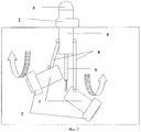
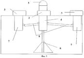
Размещение приборов и механизмов, входящих в состав систем комплекса, поясняется фиг.1-4, где на фиг.1 изображен «ПАУК» в сборном (нераскрытом) положении в разрезе, на фиг.2 показан принцип раскрытия сегментов, на фиг.3 изображен «ПАУК» в раскрытом положении, на фиг.4 изображен механизм стабилизации на волнении в разрезе.The placement of devices and mechanisms that make up the complex’s systems is illustrated in FIGS. 1–4, where FIG. 1 shows a “SPID” in an assembled (unopened) position in a section, FIG. 2 shows the principle of opening segments, FIG. 3 shows "SPIDER" in the open position, figure 4 shows the stabilization mechanism on the waves in the context.
Комплекс состоит из транспортно-пускового контейнера (фиг.1, поз.1), разделяющегося на плавающие сегменты, поддерживаемые на поверхности моря наполненными газом внешними емкостями (фиг.1, 2, 3, поз.2, 3), при этом основной сегмент (фиг.1, 2, 3, поз.4) имеет в надводной части радиолокационное приемоизлучающее устройство (фиг.1, 2, 3, поз.5), в подводной части - устройство стабилизации на волнении (фиг.1, 2, 3, поз.6), а ракетные сегменты (фиг.1, 2, 3, поз.7) соединены с основным сегментом шарнирно-штанговыми механизмами с одной степенью свободы (фиг.1, 2, 3, поз.8) в вертикальной плоскости. Комплекс содержит системы, обеспечивающие его функционирование:The complex consists of a transport and launch container (Fig. 1, pos. 1), divided into floating segments supported on the sea surface by external containers filled with gas (Figs. 1, 2, 3, pos. 2, 3), while the main segment (figure 1, 2, 3, position 4) has a radar receiving-emitting device in the surface part (figure 1, 2, 3, position 5), in the underwater part there is a wave stabilization device (figure 1, 2, 3 , pos.6), and rocket segments (Figs. 1, 2, 3, pos. 7) are connected to the main segment by articulated-rod mechanisms with one degree of freedom (Figs. 1, 2, 3, pos. 8) in vertical linen plane. The complex contains systems that ensure its functioning:
1. Систему активации и всплытия на поверхность, состоящую из:1. The system of activation and ascent to the surface, consisting of:
- стандартного электрического контактного устройства (фиг.1, поз.9), совместимого с электрическим контактным устройством торпедного аппарата, предназначенного для инициации механизмов комплекса в пусковой установке от управляющего пульта (оператора);- a standard electrical contact device (Fig. 1, item 9), compatible with an electric contact device of a torpedo tube, designed to initiate complex mechanisms in a launcher from a control panel (operator);
- стандартного механического контактного устройства (фиг.1, поз.10), предназначенного для фиксации момента выхода комплекса из пусковой установки и передачи сигнала в бортовой компьютер;- a standard mechanical contact device (figure 1, pos. 10), designed to fix the moment the complex leaves the launcher and transmits a signal to the on-board computer;
- порохового реактивного ускорителя (фиг.1, поз.11) с рулевыми машинками и рулями (фиг.1, поз.12), предназначенного для перевода комплекса в вертикальное положения и ускоренного всплытия на поверхность;- powder rocket accelerator (figure 1, item 11) with steering cars and rudders (figure 1, item 12), designed to translate the complex into a vertical position and accelerated ascent to the surface;
- внешней газовой емкости основного сегмента (фиг.1, 2, 3, поз.2), предназначенной для придания комплексу положительной плавучести на конечном участке всплытия, а также создания уверенной плавучести основного сегмента комплекса на поверхности. В нераскрытом положении газовые емкости упакованы во внешние ниши корпуса и прикрыты самораскрывающимися щитками (фиг.1, поз.13);- external gas container of the main segment (Fig. 1, 2, 3, item 2), designed to give the complex positive buoyancy at the final section of the ascent, as well as to create confident buoyancy of the main segment of the complex on the surface. In the unopened position, gas containers are packed in external niches of the casing and covered with self-opening shields (Fig. 1, item 13);
- баллона ГВД (газа высокого давления) или газового генератора (фиг.1, поз.14), предназначенного для заполнения внешней газовой емкости газом;- cylinder high pressure gas (high pressure gas) or gas generator (figure 1, item 14), designed to fill the external gas tank with gas;
- бортового источника электропитания аккумуляторного типа (фиг.1, поз.15), предназначенного для обеспечения электропитанием систем и механизмов комплекса;- an on-board power source of the battery type (Fig. 1, item 15), designed to provide power to the systems and mechanisms of the complex;
- блока управления (бортового компьютера с исполнительными механизмами) (фиг.1, поз.16), предназначенного для управления взаимодействием систем и механизмов комплекса по заданной программе;- control unit (on-board computer with actuators) (Fig. 1, item 16), designed to control the interaction of systems and mechanisms of the complex according to a given program;
- блока гидростатических датчиков (фиг.1, поз.17), предназначенных для передачи сигналов в блок управления о достижении определенной глубины всплытия.- block hydrostatic sensors (figure 1, pos.17), designed to transmit signals to the control unit to achieve a certain depth of ascent.
2. Систему развертывания, состоящую из:2. Deployment system, consisting of:
- пироболтов отделения, предназначенных для отделения реактивного ускорителя (фиг.1, поз.18) и ракетных сегментов (фиг.1, поз.19) от основного сегмента контейнера;- pyro-bolts of the compartment, designed to separate the jet accelerator (Fig. 1, pos. 18) and rocket segments (Fig. 1, pos. 19) from the main segment of the container;
- шарнирно-штанговых механизмов с одной степенью свободы (фиг.1, 2, 3, поз 8), связывающих ракетные сегменты с основным. В нераскрытом положении штанги утоплены в ниши корпуса транспортно-пускового контейнера;- articulated-rod mechanisms with one degree of freedom (Fig. 1, 2, 3, item 8), connecting missile segments with the main one. In the unopened position, the rods are recessed into the niches of the transport launch container body;
- внешних газовых емкостей ракетных сегментов (фиг.1, 2, 3, поз.3), предназначенных для придания устойчивой плавучести ракетным сегментам;- external gas tanks of the rocket segments (FIGS. 1, 2, 3, item 3), designed to give stable buoyancy to the rocket segments;
- баллонов ГВД или газовых генераторов ракетных сегментов (фиг.1, поз.20), предназначенных для наполнения газом внешних газовых емкостей ракетных сегментов.- cylinders GVD or gas generators of the rocket segments (Fig.1, pos.20), designed to fill the gas external gas tanks of the rocket segments.
3. Систему стабилизации и учета углов крена на волнении, состоящую из:3. The system of stabilization and accounting of roll angles in waves, consisting of:
- выдвижного механизма стабилизации на волнении типа «плавучий якорь» (фиг.1, 2, 3, 4, поз.6), предназначенного для снижения раскачивания комплекса на волнении, состоящего из пневмоцилиндра (фиг.4, поз.21), выдвижного фиксируемого в нижнем положении пневмоштока (фиг.4, поз.22) с откидывающимися под действием пружинного механизма (фиг.4, поз.23) четырьмя лопастями из эластичного водонепроницаемого материала (фиг.4, поз.24), натянутого на реи (фиг.4, поз.25), фиксируемые в откинутом положении проволочными струнами (фиг.4, поз.26);- retractable stabilization mechanism on waves “floating anchor” type (Fig. 1, 2, 3, 4, item 6), designed to reduce the swing of the complex on a wave, consisting of a pneumatic cylinder (Fig. 4, item 21), retractable in the lower position of the pneumatic rod (Fig. 4, item 22) with four blades reclining under the action of the spring mechanism (Fig. 4, item 23) of elastic waterproof material (Fig. 4, item 24), stretched over the yokes (Fig. 4, pos. 25), fixed in the tilted position by wire strings (Fig. 4, pos. 26);
- блока учета углов крена (гироскопических приборов основного сегмента), расположенных в блоке управления (фиг.1, поз.27), предназначенных для определения и передачи в блок управления мгновенных значений крена комплекса на волнении.- a unit for accounting roll angles (gyroscopic instruments of the main segment) located in the control unit (Fig. 1, item 27), designed to determine and transmit to the control unit the instantaneous roll values of the complex on a wave.
4. Систему поиска и локализации целей, состоящую из:4. The system of search and localization of goals, consisting of:
- приемоизлучающего устройства (ПИУ) (фиг.1, 2, 3, поз.5), предназначенного для передачи и приема радиолокационных сигналов;- receiving-emitting device (PIE) (figure 1, 2, 3, item 5), designed to transmit and receive radar signals;
- электронного радиолокационного блока (фиг.1, поз.28), предназначенного для формирования радиолокационных импульсов и обработки принятых сигналов;- electronic radar unit (figure 1, pos. 28), designed to generate radar pulses and process the received signals;
- логического устройства РЛС (компьютера РЛС), входящего в состав электронного радиолокационного блока (фиг.1, поз.29), предназначенного для управления излучением и приемом сигналов, а также классификации принятых сигналов по заданным признакам.- logical device radar (computer radar), which is part of the electronic radar unit (figure 1, pos.29), designed to control the emission and reception of signals, as well as the classification of received signals according to specified criteria.
5. Систему поражения целей, состоящую из:5. Target destruction system, consisting of:
- самонаводящихся зенитных ракет (фиг.1, поз.30), размещенных в ракетных сегментах (фиг.1, 2, 3, поз.7), предназначенных для непосредственного поражения целей;- homing anti-aircraft missiles (figure 1, pos. 30), located in the missile segments (figures 1, 2, 3, pos. 7), designed to directly hit targets;
- кабелей электропитания и управления (фиг.1, поз.31), размещенных в полых шарнирно-штанговых механизмах, соединяющих основной и ракетные сегменты (фиг.1, 2, 3, поз.8), предназначенных для подачи управляющих сигналов к механизмам ракетных сегментов и реактивного ускорителя.- power supply and control cables (Fig. 1, pos. 31), placed in hollow swivel-rod mechanisms connecting the main and rocket segments (Figs. 1, 2, 3, pos. 8), designed to supply control signals to the rocket mechanisms segments and a jet accelerator.
6. Систему самоуничтожения, состоящую из:6. Self-destruction system, consisting of:
- заряда взрывчатого вещества с электродетонатором, размещенного в основном сегменте (фиг.1, поз.32), предназначенного для подрыва аппаратуры и внешней газовой емкости основного сегмента;- explosive charge with an electric detonator located in the main segment (Fig. 1, item 32), designed to undermine the equipment and the external gas tank of the main segment;
- зарядов взрывчатого вещества зенитных ракет, размещенных в ракетных сегментах (фиг.1, поз.33), предназначенных для подрыва ЗУР и внешних газовых емкостей ракетных сегментов;- charges of the explosive of anti-aircraft missiles located in the missile segments (Fig. 1, pos. 33), designed to undermine the SAM and external gas tanks of the missile segments;
- электронного командного устройства самоуничтожения (конструктивно входит в блок управления) (фиг.1, поз.15), предназначенного для подачи команды на самоуничтожение комплекса по заданным признакам;- electronic command device of self-destruction (structurally included in the control unit) (Fig. 1, item 15), designed to send a command for self-destruction of the complex according to the specified criteria;
- гидростата атмосферного давления, расположенного в нижней части основного сегмента (фиг.1, поз.34), предназначенного для подачи сигнала в электронное командное устройство самоуничтожения об извлечении комплекса из воды (один из признаков самоуничтожения).- atmospheric pressure hydrostat located in the lower part of the main segment (Fig. 1, item 34), designed to send a signal to the electronic self-destruction command device to remove the complex from the water (one of the signs of self-destruction).
Работа устройстваDevice operation
Способ обеспечения боевой устойчивости ПЛ от атак противолодочной авиации, заключающийся в поражении воздушных объектов самонаводящимися зенитными ракетами, стартующими в надводном положении из реактивно-всплывающего транспортно-пускового контейнера, выстреливаемого из пусковой установки подводной лодки, находящейся в подводном положении, отличающийся долговременностью и многоканальностью боевого воздействия, при этом системы и механизмы комплекса автономно осуществляют следующие операции:A method of ensuring combat stability of a submarine from anti-submarine aircraft attacks, which consists in hitting air objects by homing anti-aircraft missiles launched from a rocket transport and launch container in an underwater position fired from a submarine launcher in an underwater position, characterized by long duration and multi-channel combat action , while the systems and mechanisms of the complex autonomously carry out the following operations:
1. Всплытие на поверхность под воздействием реактивного ускорителя и (или) положительной плавучести внешней газовой емкости.1. Surfacing to the surface under the influence of a jet accelerator and (or) positive buoyancy of an external gas tank.
2. Разделение на сегменты, с сохранением электропитания, управления и единой системы координат для всех сегментов.2. Separation into segments, while maintaining power supply, control and a single coordinate system for all segments.
3. Придание сегментам уверенной положительной плавучести за счет собственных внешних плавучих газовых емкостей;3. Giving the segments confident positive buoyancy due to their own external floating gas tanks;
4. Задействование механической системы стабилизации и электронной системы учета морского волнения.4. Involvement of the mechanical stabilization system and the electronic system of sea waves.
5. Осуществление поиска воздушных (морских) целей путем радиолоцирования воздушной полусферы.5. The search for air (sea) targets by radiolocation of the air hemisphere.
6. Осуществление классификации целей по заданным признакам.6. The implementation of the classification of goals according to specified criteria.
7. Выдачу данных целеуказания (траектории полета) самонаводящимся зенитным ракетам.7. The issuance of target designation data (flight paths) to homing anti-aircraft missiles.
8. Запуск зенитных ракет.8. Launch of anti-aircraft missiles.
9. Повторение пп.5-9 при необходимости.9. Repeat paragraphs 5-9 if necessary.
10. Самоуничтожение комплекса по заданному признаку.10. Self-destruction of the complex for a given sign.
Подводная лодка, находящаяся в подводном положении, обнаруживает наличие противолодочной авиации в районе по характерным признакам гидроакустической станцией. При этом местоположение целей, как правило, неизвестно. «ПАУК» находится в торпедном аппарате, заполненном водой (дежурном). По приказу на применение оператор пульта управления торпедными аппаратами подает электропитание на комплекс и команду на открытие передней крышки ТА. Электропитание через стандартное электрическое контактное устройство (фиг.1, поз.9) поступает к бортовому источнику электропитания (фиг.1, поз.15), инициируя его, далее к блоку управления (фиг.1, поз.16), где происходит разогрев и включение бортового компьютера, к блоку учета углов крена (гироскопических приборов основного сегмента), расположенных в блоке управления (фиг.1, поз.16), где происходит разгон и арретирование гироскопов, а также через кабели электропитания и управления (фиг.1, поз.31), размещенные в полых шарнирно-штанговых механизмах, соединяющих основной и ракетные сегменты (фиг.1, поз.8), поступает на разгон и арретирование гироскопов зенитных ракет (фиг.1, поз.30) в ракетных сегментах (фиг.1, поз.7). К моменту открытия передней крышки ТА электропитание механизмов комплекса передается бортовому источнику электропитания (фиг.1, поз.15). Выбрасывание «ПАУКА» из ТА осуществляется стандартным способом (воздухом или водой высокого давления), при этом происходит потеря жесткого контакта стандартного механического контактного устройства (фиг.1, поз.10) с дорожкой торпедного аппарата, о чем передается сигнал в блок управления (фиг.1, поз.16).The submarine, located in an underwater position, detects the presence of anti-submarine aircraft in the area according to the characteristic signs of a sonar station. Moreover, the location of the targets is usually unknown. "SPIDER" is located in a torpedo tube filled with water (on duty). By order of application, the operator of the control panel of the torpedo tubes supplies power to the complex and a command to open the front cover of the TA. Power supply through a standard electric contact device (Fig. 1, pos. 9) is supplied to the on-board power supply (Fig. 1, pos. 15), initiating it, then to the control unit (Fig. 1, pos. 16), where heating occurs and turning on the on-board computer to the roll angle meter (gyroscopic instruments of the main segment) located in the control unit (Fig. 1, pos. 16), where the gyroscopes are accelerated and arrested, as well as through power and control cables (Fig. 1, pos. 31), placed in hollow hinged-rod mechanisms, the main and missile segments (Fig. 1, pos. 8), it is used to disperse and arrest gyroscopes of anti-aircraft missiles (Fig. 1, pos. 30) in the missile segments (Fig. 1, pos. 7). By the time the front cover TA is opened, the power supply of the complex mechanisms is transferred to the on-board power supply (Fig. 1, item 15). The SPIDER is ejected from the TA by the standard method (high pressure air or water), and the hard contact of the standard mechanical contact device (Fig. 1, pos. 10) with the torpedo tube track is lost, which is transmitted to the control unit (Fig. .1, pos. 16).
После выхода комплекса из торпедного аппарата подводная лодка свободно маневрирует в соответствии с предписаниями руководящих документов. Далее возможны два варианта всплытия «ПАУКа»:After the complex leaves the torpedo tube, the submarine maneuvers freely in accordance with the requirements of the guidelines. Next, there are two options for the ascent of the "Spider":
1. Если сигнал о начальной глубине комплекса, поступивший от блока гидростатических датчиков (фиг.1, поз.17) в блок управления (фиг.1, поз.16) больше установленного, то блок управления (фиг.1, поз.16) подает команду на запуск двигателя реактивного ускорителя (фиг.1, поз.11). Далее блок управления (фиг.1, поз.16), управляя рулями реактивного ускорителя (фиг.1, поз.12), руководствуясь сигналами гироскопов, переводит комплекс в вертикальное положение и управляет процессом всплытия. После получения сигнала от блока гидростатических датчиков (фиг.1, поз.17) о достижении заданной глубины блок управления (фиг.1, поз.16) подает команду на подрыв пироболтов отделения реактивного ускорителя (фиг.1, поз.18) и перекладывает рули (фиг.1, поз.12) таким образом, чтобы резко перевести траекторию движения комплекса в горизонтальную плоскость. При этом реактивный ускоритель отсоединяется от транспортно-пускового контейнера. После сброса реактивного ускорителя блок управления (фиг.1, поз.16) подает команду на открытие запирающего клапана баллона ГВД (фиг.2, поз.14), откуда газ поступает во внешнюю газовую емкость основного сегмента (фиг.1, 2, 3, поз.2), при этом внутренним давлением сбрасываются щитки (фиг.1, поз.13) и емкость раскрывается. Всплытие транспортно-пускового контейнера на конечном участке пути происходит за счет положительной плавучести внешней газовой емкости основного сегмента.1. If the signal about the initial depth of the complex, received from the block of hydrostatic sensors (Fig. 1, pos. 17) to the control unit (Fig. 1, pos. 16) is greater than the installed one, then the control unit (Fig. 1, pos. 16) gives the command to start the engine of the jet accelerator (figure 1, item 11). Next, the control unit (Fig. 1, pos. 16), controlling the rudders of a jet accelerator (Fig. 1, pos. 12), guided by the signals of gyroscopes, puts the complex in a vertical position and controls the ascent process. After receiving a signal from the unit of hydrostatic sensors (Fig. 1, pos. 17) about reaching a predetermined depth, the control unit (Fig. 1, pos. 16) gives a command to detonate the pyro-bolts of the jet accelerator compartment (Fig. 1, pos. 18) and transfers steering wheels (figure 1, item 12) so as to sharply translate the trajectory of the complex into a horizontal plane. In this case, the jet accelerator is disconnected from the transport and launch container. After resetting the jet accelerator, the control unit (Fig. 1, pos. 16) gives a command to open the shut-off valve of the cylinder of the GVD (Fig. 2, pos. 14), from where the gas enters the external gas tank of the main segment (Figs. 1, 2, 3 , pos.2), while the internal pressure drops flaps (figure 1, pos.13) and the capacity is revealed. Ascent of the transport and launch container at the final section of the track is due to the positive buoyancy of the external gas tank of the main segment.
2. Если сигнал о начальной глубине комплекса, поступивший от блока гидростатических датчиков (фиг.1, поз.17) в блок управления (фиг.1, поз.16), меньше установленного, то блок управления (фиг.1, поз.16) подает команду на подрыв пироболтов отделения реактивного ускорителя (фиг.1, поз.18) без запуска реактивного двигателя. После сброса реактивного ускорителя блок управления (фиг.1, поз.16) подает команду на открытие запирающего клапана баллона ГВД (фиг.2, поз.14), откуда газ поступает во внешнюю газовую емкость основного сегмента (фиг.1, 2, 3, поз.2), при этом внутренним давлением сбрасываются щитки (фиг.1, поз.13) и емкость раскрывается. Всплытие транспортно-пускового контейнера происходит за счет положительной плавучести внешней газовой емкости основного сегмента.2. If the signal about the initial depth of the complex, received from the block of hydrostatic sensors (Fig. 1, pos. 17) in the control unit (Fig. 1, pos. 16), is less than the installed one, then the control unit (Fig. 1, pos. 16 ) gives a command to detonate the pyro-bolts of the jet accelerator compartment (Fig. 1, pos. 18) without starting the jet engine. After resetting the jet accelerator, the control unit (Fig. 1, pos. 16) gives a command to open the shut-off valve of the cylinder of the GVD (Fig. 2, pos. 14), from where the gas enters the external gas tank of the main segment (Figs. 1, 2, 3 , pos.2), while the internal pressure drops flaps (figure 1, pos.13) and the capacity is revealed. Ascent of the launch container occurs due to the positive buoyancy of the external gas tank of the main segment.
При достижении поверхности блок гидростатических датчиков (фиг.1, поз.17) подает сигнал в блок управления (фиг.1, поз.16), блок управления (фиг.1, поз.16) подает команду на подрыв пироболтов отделения ракетных сегментов (фиг.1, поз.19), на открытие запирающих клапанов баллонов ГВД ракетных сегментов (фиг.1, поз.20) и подачи газа во внешние газовые емкости ракетных сегментов (фиг.1, 2, 3, поз.3), а также команды на запирающий клапан баллона ГВД основного сегмента и подачи газа в пневмоцилиндр (фиг.4 поз.21) выдвижного механизма стабилизации на волнении (фиг.1, 2, 3, 4, поз.6).When the surface is reached, the hydrostatic sensor unit (Fig. 1, pos. 17) sends a signal to the control unit (Fig. 1, pos. 16), the control unit (Fig. 1, pos. 16) gives a command to detonate the pyro-bolts of the missile segment separation ( figure 1, pos.19), to open the locking valves of the cylinders GVD rocket segments (figure 1, pos.20) and supply gas to the external gas tanks of the rocket segments (figure 1, 2, 3, pos.3), and also the command for the locking valve of the cylinder of the high pressure water supply of the main segment and the gas supply to the pneumatic cylinder (figure 4 pos. 21) of the sliding stabilization mechanism on a wave (figure 1, 2, 3, 4, item 6).
Под давлением газа пневмошток (фиг.4, поз.22) выдвигается, толкая отделившиеся ракетные сегменты (фиг.1, 2, 3, поз.7) и натягивая пружинный механизм (фиг.4, поз.23) раскрытия лопастей устройства. В крайнем нижнем положении пневмошток (фиг.4, поз.22) фиксируется защелками, при этом освобождаются реи (фиг.4, поз 25) и откидываются под действием пружинного механизма до натяжения проволочных струн (фиг.4, поз.26). Четыре лопасти из водонепроницаемого эластичного материала (фиг.4, поз.24), натянутые на реи и струны, находившиеся внутри пневмоштока, распрямляются и создают плавучий якорь, препятствующий раскачиванию комплекса на волнении.Under gas pressure, the pneumatic rod (Fig. 4, item 22) extends, pushing the separated rocket segments (Fig. 1, 2, 3, item 7) and pulling the spring mechanism (Fig. 4, item 23) of the disclosure of the blades of the device. In the lowermost position, the pneumatic rod (Fig. 4, item 22) is fixed with latches, while the shafts are released (Fig. 4, item 25) and recline under the action of the spring mechanism until the wire strings are tensioned (Fig. 4, item 26). Four blades of waterproof elastic material (Fig. 4, item 24), stretched over yards and strings inside the pneumatic rod, straighten and create a floating anchor, which prevents the complex from swaying on a wave.
Ракетные сегменты (фиг.1, 2, 3, поз.7), удерживаемые шарнирно-штанговыми механизмами (фиг.1, 2, 3, поз.8), под воздействием положительной плавучести газовых емкостей разворачиваются и циркуляционно всплывают в надводное положение.Missile segments (Figs. 1, 2, 3, pos. 7), held by articulated-rod mechanisms (Figs. 1, 2, 3, pos. 8), are deployed under the influence of positive buoyancy of gas tanks and circulate to the surface above the surface.
Электропитание для прогрева аппаратуры и инициации электронного радиолокационного блока (фиг.1, поз.28) и логического устройства РЛС (компьютера РЛС) (фиг.1, поз.29) подается одновременно с началом всплытия комплекса. После раскрытия механизма стабилизации (фиг.1, 2, 3, 4, поз.6) и всплытия ракетных сегментов (фиг.1, 2, 3, поз.7) через установленную временную задержку, предназначенную для стабилизации комплекса на поверхности, блок управления (фиг.1, поз.16) подает команду в логическое устройство РЛС (фиг.1, поз.29) на начало поиска целей. Логическое устройство РЛС (фиг.1, поз.29) по заданной программе управляет формированием, излучением и приемом сигналов, создаваемых аппаратурой электронного радиолокационного блока (фиг.1, поз.28), излучаемых и принимаемых радиолокационным приемоизлучающим устройством (фиг.1, 2, 3, поз.5). Классификация целей осуществляется в логическом устройстве РЛС (фиг.1, поз.29) путем сравнения по заданной программе признаков принятых сигналов с заложенными эталонными значениями. Если полученные сигналы классифицированы как цель боевого воздействия, то ее текущие координаты передаются в блок управления (фиг.1, поз.16), где корректируются поправкой, полученной от блока учета углов крена (гироскопических приборов основного сегмента) (фиг.1, поз.27). Далее бортовой компьютер блока управления по заданной программе определяет траекторию полета зенитных ракет и передает данные в инерциальную систему управления ЗУР. После этого блок управления (фиг.1, поз.16) подает команду на запуск ракет. В момент старта первая ракета сбрасывает пластиковую крышку ракетного сегмента, предохраняющую от попадания воды, поднимается вертикально на заданную высоту, осуществляет запрограммированный разворот на боевой курс и сканирует пространство собственной ГСН в процессе полета. Такая последовательность операций осуществляется относительно каждой из целей, классифицированных как объект атаки. По истечении максимального времени полета ракет комплекс вновь осуществляет поиск и классификацию целей, и, если таковые обнаружены, обстреливает их повторно, до полного израсходования боезапаса ЗУР.Power supply for heating the equipment and initiating the electronic radar unit (Fig. 1, pos. 28) and the logical device of the radar (radar computer) (Fig. 1, pos. 29) is supplied simultaneously with the start of the ascent of the complex. After the disclosure of the stabilization mechanism (Fig. 1, 2, 3, 4, item 6) and the ascent of the rocket segments (Fig. 1, 2, 3, item 7) after a set time delay, designed to stabilize the complex on the surface, the control unit (Fig. 1, pos. 16) sends a command to the radar logic device (Fig. 1, pos. 29) at the beginning of the search for targets. The logical device of the radar (Fig. 1, pos. 29), according to a given program, controls the generation, emission and reception of signals generated by the equipment of the electronic radar unit (Fig. 1, pos. 28), emitted and received by the radar transceiver (Fig. 1, 2 , 3, item 5). The classification of targets is carried out in the logical device of the radar (Fig. 1, pos. 29) by comparing, according to a given program, the signs of received signals with embedded reference values. If the received signals are classified as a target of combat action, then its current coordinates are transmitted to the control unit (Fig. 1, pos. 16), where they are adjusted by the correction received from the roll angle meter (gyroscopic devices of the main segment) (Fig. 1, pos. 27). Next, the on-board computer of the control unit according to a predetermined program determines the flight path of the anti-aircraft missiles and transmits data to the inertial control system of the SAM. After that, the control unit (Fig. 1, pos. 16) gives a command to launch rockets. At the time of launch, the first rocket drops the plastic cover of the rocket segment, which prevents water ingress, rises vertically to a predetermined height, carries out a programmed turn to the combat course and scans the space of its own seeker during the flight. This sequence of operations is carried out relative to each of the targets classified as an object of attack. After the maximum missile flight time has elapsed, the complex again searches for and classifies targets, and, if any, detonates them again, until the ammunition is fully used up.
Если при первичном поиске не обнаружены цели, классифицируемые как объект атаки, по команде логического устройства РЛС (фиг.1, поз.29) электронный радиолокационный блок (фиг.1, поз.28) переходит в пассивный режим работы, осуществляя поиск сигналов радиоизлучающих устройств, присущих объектам атаки, в заданных диапазонах частот. При обнаружении таких сигналов либо по истечении заданного времени комплекс вновь переходит в активный режим поиска.If the primary search did not detect targets that are classified as an object of attack, by the command of the logical device of the radar (Fig. 1, pos. 29), the electronic radar unit (Fig. 1, pos. 28) goes into passive mode, searching for signals from radio-emitting devices inherent in the objects of attack in the given frequency ranges. If such signals are detected, or after a predetermined time, the complex again enters the active search mode.
Самоуничтожение комплекса производится по команде электронного командного устройства самоуничтожения (конструктивно входящего в блок управления) (фиг.1, поз.15) путем подрыва заряда взрывчатого вещества с электродетонатором, размещенного в основном сегменте (фиг.1, поз.32), а также зарядов взрывчатого вещества зенитных ракет, размещенных в ракетных сегментах (фиг.1, поз.33), по следующим признакам:Self-destruction of the complex is carried out at the command of the electronic command device of self-destruction (structurally included in the control unit) (Fig. 1, item 15) by undermining the explosive charge with an electric detonator located in the main segment (Fig. 1, item 32), as well as charges explosive anti-aircraft missiles located in the missile segments (Fig.1, pos.33), according to the following signs:
- при полном израсходовании боезапаса ЗУР;- with the full use of ammunition missiles;
- при израсходовании энергозапасов бортового источника питания более чем на 90%;- when the energy reserves of the on-board power supply are used up by more than 90%;
- по истечении заданного времени действия комплекса, установленного в таймер блока управления;- after a predetermined time of the complex, set in the timer of the control unit;
- по сигналу от гидростата атмосферного давления, расположенного в нижней части основного сегмента (фиг.1, поз.34), при несанкционированном извлечении комплекса из воды.- by a signal from a atmospheric pressure hydrostat located in the lower part of the main segment (Fig. 1, item 34), during unauthorized removal of the complex from water.
Claims (2)
Priority Applications (1)
| Application Number | Priority Date | Filing Date | Title |
|---|---|---|---|
| RU2008105175/02A RU2382313C2 (en) | 2008-02-11 | 2008-02-11 | Antiaircraft self-contained complex of submarine self-defense (sds "spider") and method of its use |
Applications Claiming Priority (1)
| Application Number | Priority Date | Filing Date | Title |
|---|---|---|---|
| RU2008105175/02A RU2382313C2 (en) | 2008-02-11 | 2008-02-11 | Antiaircraft self-contained complex of submarine self-defense (sds "spider") and method of its use |
Publications (2)
| Publication Number | Publication Date |
|---|---|
| RU2008105175A RU2008105175A (en) | 2009-08-20 |
| RU2382313C2 true RU2382313C2 (en) | 2010-02-20 |
Family
ID=41150647
Family Applications (1)
| Application Number | Title | Priority Date | Filing Date |
|---|---|---|---|
| RU2008105175/02A RU2382313C2 (en) | 2008-02-11 | 2008-02-11 | Antiaircraft self-contained complex of submarine self-defense (sds "spider") and method of its use |
Country Status (1)
| Country | Link |
|---|---|
| RU (1) | RU2382313C2 (en) |
Cited By (4)
| Publication number | Priority date | Publication date | Assignee | Title |
|---|---|---|---|---|
| RU2453861C1 (en) * | 2010-10-11 | 2012-06-20 | Российская Федерация, от имени которой выступает Министерство промышленности и торговли Российской Федерации (Минпромторг России) | Hydroacoustic receiving-radiating track |
| RU2532279C1 (en) * | 2013-04-11 | 2014-11-10 | Открытое Акционерное Общество "Государственное Машиностроительное Конструкторское Бюро "Радуга" Имени А.Я. Березняка" | Submarine |
| RU2543436C1 (en) * | 2013-09-25 | 2015-02-27 | Вячеслав Константинович Цой | Pseudo simulator of launch system |
| RU186630U1 (en) * | 2018-07-24 | 2019-01-28 | Акционерное общество "Стелла-К" | Anti-aircraft missile homing warhead equipped with an acoustic direction-finding sensor for target coordinates |
-
2008
- 2008-02-11 RU RU2008105175/02A patent/RU2382313C2/en not_active IP Right Cessation
Cited By (5)
| Publication number | Priority date | Publication date | Assignee | Title |
|---|---|---|---|---|
| RU2453861C1 (en) * | 2010-10-11 | 2012-06-20 | Российская Федерация, от имени которой выступает Министерство промышленности и торговли Российской Федерации (Минпромторг России) | Hydroacoustic receiving-radiating track |
| RU2532279C1 (en) * | 2013-04-11 | 2014-11-10 | Открытое Акционерное Общество "Государственное Машиностроительное Конструкторское Бюро "Радуга" Имени А.Я. Березняка" | Submarine |
| RU2543436C1 (en) * | 2013-09-25 | 2015-02-27 | Вячеслав Константинович Цой | Pseudo simulator of launch system |
| RU2543436C9 (en) * | 2013-09-25 | 2015-05-10 | Вячеслав Константинович Цой | Pseudo simulator of launch system |
| RU186630U1 (en) * | 2018-07-24 | 2019-01-28 | Акционерное общество "Стелла-К" | Anti-aircraft missile homing warhead equipped with an acoustic direction-finding sensor for target coordinates |
Also Published As
| Publication number | Publication date |
|---|---|
| RU2008105175A (en) | 2009-08-20 |
Similar Documents
| Publication | Publication Date | Title |
|---|---|---|
| US6610971B1 (en) | Ship self-defense missile weapon system | |
| US20200064112A1 (en) | Visual guidance system for barrel-fired projectiles | |
| RU2382313C2 (en) | Antiaircraft self-contained complex of submarine self-defense (sds "spider") and method of its use | |
| RU2624258C2 (en) | Weapons system for onshore assets destruction and method of its application from the underwater platforms | |
| US5214618A (en) | Method and arrangement for combating a submerged target object | |
| RU2413156C1 (en) | Controlled independent universal positional underwater anti-aircraft (anti-ship) complex ("spider") and method of its implementation | |
| RU2544446C1 (en) | Rolling cruise missile | |
| RU2713546C2 (en) | Cruise missile and method of combat use thereof | |
| RU2511211C2 (en) | False sea target system | |
| RU2613632C2 (en) | Method of concealed underwater movement of unmanned aerial vehicle and its release at launching base | |
| RU2622051C2 (en) | Cruise missile universal in score and engagement methods | |
| JP4888941B2 (en) | Anti-aircraft ultra high-speed flying bullets and anti-aircraft attack methods using them | |
| RU2093783C1 (en) | Method of firing from deck launcher of antisubmarine missile complex | |
| RU2175626C2 (en) | Flying vehicle for destruction of object (versions) | |
| RU105422U1 (en) | RECOGNITION-FIRE COMPLEX OF TANK WEAPONS | |
| RU2546726C1 (en) | Antisubmarine cruise missile and its application method | |
| RU2714274C2 (en) | Cruise missile with self-contained unmanned underwater vehicle-mine | |
| RU2733732C1 (en) | Method of protecting surface ship and vessel from damage by torpedo | |
| CN114993107A (en) | Submarine striking system and striking method | |
| RU70359U1 (en) | RECOGNITION-FIRE COMPLEX OF TANK WEAPONS | |
| NO313957B1 (en) | Method of combating sea mines and apparatus for use in carrying out the method | |
| RU2733734C2 (en) | Method of destroying sea target by torpedoes | |
| RU2680919C1 (en) | Mobile active device for protection of different objects from unmanned controlled automotive weapons | |
| US20060180044A1 (en) | Anti-submarine warfare cluster munitions an cluster depth charges | |
| RU2796086C1 (en) | Rocket glider with homing underwater projectile |
Legal Events
| Date | Code | Title | Description |
|---|---|---|---|
| MM4A | The patent is invalid due to non-payment of fees |
Effective date: 20130212 |