RU2377458C2 - Operation method of power rotation drive and power plant for its implementation - Google Patents
Operation method of power rotation drive and power plant for its implementation Download PDFInfo
- Publication number
- RU2377458C2 RU2377458C2 RU2008105388/11A RU2008105388A RU2377458C2 RU 2377458 C2 RU2377458 C2 RU 2377458C2 RU 2008105388/11 A RU2008105388/11 A RU 2008105388/11A RU 2008105388 A RU2008105388 A RU 2008105388A RU 2377458 C2 RU2377458 C2 RU 2377458C2
- Authority
- RU
- Russia
- Prior art keywords
- link
- rotation
- power plant
- working
- plant according
- Prior art date
Links
Images

Classifications
-
- F—MECHANICAL ENGINEERING; LIGHTING; HEATING; WEAPONS; BLASTING
- F16—ENGINEERING ELEMENTS AND UNITS; GENERAL MEASURES FOR PRODUCING AND MAINTAINING EFFECTIVE FUNCTIONING OF MACHINES OR INSTALLATIONS; THERMAL INSULATION IN GENERAL
- F16H—GEARING
- F16H33/00—Gearings based on repeated accumulation and delivery of energy
- F16H33/20—Gearings based on repeated accumulation and delivery of energy for interconversion, based essentially on inertia, of rotary motion and reciprocating or oscillating motion
-
- F—MECHANICAL ENGINEERING; LIGHTING; HEATING; WEAPONS; BLASTING
- F03—MACHINES OR ENGINES FOR LIQUIDS; WIND, SPRING, OR WEIGHT MOTORS; PRODUCING MECHANICAL POWER OR A REACTIVE PROPULSIVE THRUST, NOT OTHERWISE PROVIDED FOR
- F03G—SPRING, WEIGHT, INERTIA OR LIKE MOTORS; MECHANICAL-POWER PRODUCING DEVICES OR MECHANISMS, NOT OTHERWISE PROVIDED FOR OR USING ENERGY SOURCES NOT OTHERWISE PROVIDED FOR
- F03G3/00—Other motors, e.g. gravity or inertia motors
- F03G3/08—Other motors, e.g. gravity or inertia motors using flywheels
-
- Y—GENERAL TAGGING OF NEW TECHNOLOGICAL DEVELOPMENTS; GENERAL TAGGING OF CROSS-SECTIONAL TECHNOLOGIES SPANNING OVER SEVERAL SECTIONS OF THE IPC; TECHNICAL SUBJECTS COVERED BY FORMER USPC CROSS-REFERENCE ART COLLECTIONS [XRACs] AND DIGESTS
- Y10—TECHNICAL SUBJECTS COVERED BY FORMER USPC
- Y10T—TECHNICAL SUBJECTS COVERED BY FORMER US CLASSIFICATION
- Y10T74/00—Machine element or mechanism
- Y10T74/18—Mechanical movements
- Y10T74/18056—Rotary to or from reciprocating or oscillating
- Y10T74/18344—Unbalanced weights
Landscapes
- Engineering & Computer Science (AREA)
- Chemical & Material Sciences (AREA)
- Combustion & Propulsion (AREA)
- General Engineering & Computer Science (AREA)
- Mechanical Engineering (AREA)
- Connection Of Motors, Electrical Generators, Mechanical Devices, And The Like (AREA)
- One-Way And Automatic Clutches, And Combinations Of Different Clutches (AREA)
- Hybrid Electric Vehicles (AREA)
Abstract
Description
Изобретение относится к способам работы силовых приводов вращательного движения, в частности к инерционным системам накопления и преобразования энергии, и может быть использовано для привода различных машин, транспортных средств и др.The invention relates to methods of operation of rotary motion power drives, in particular to inertial energy storage and conversion systems, and can be used to drive various machines, vehicles, etc.
Известны инерционные (маховичные) двигатели, в которых энергия запасается в виде механической энергии быстровращающегося ротора, а затем используется для приведения в действие различных устройств (см., например, Гулиа Н.В. Инерция. - М.: Наука, 1982; Гулиа Н.В. Инерционные аккумуляторы энергии. Воронеж. Изд-во Воронежского университета, 1973). В известных инерционных двигателях на совершение полезной работы расходуется кинетическая энергия вращения маховичного аккумулятора, который в результате тормозится.Inertial (flywheel) engines are known in which energy is stored in the form of mechanical energy of a rapidly rotating rotor and then used to drive various devices (see, for example, Gulia N.V. Inertia. - M .: Nauka, 1982; Gulia N .V. Inertial energy accumulators. Voronezh. Voronezh University Press, 1973). In known inertial engines, the kinetic energy of rotation of the flywheel accumulator is consumed to complete useful work, which, as a result, is inhibited.
Известны устройства в виде передач вращения с аккумулированием и повторной отдачей энергии, в которых для этого используется вращение неуравновешенных масс (например, DE 2612035 A1, опубл. 22.03.1976; FR 1588205, опубл. 10.04.1970; US 3960036, 01.06.1976). В частности, известно устройство ускорения масс и преобразования энергии (патент US 4498357, опубл. 12.02.1985), в котором используют механизм прерывистого движения, содержащего рабочее звено, согласно которому с помощью источника механических колебаний создают знакопеременный момент вращения и прикладывают его к рабочему звену, выполненному с возможностью вращения.Known devices in the form of rotational gears with accumulation and re-release of energy, which use the rotation of unbalanced masses (for example, DE 2612035 A1, publ. 03/22/1976; FR 1588205, publ. 04/10/1970; US 3960036, 06/01/1976) . In particular, a mass acceleration and energy conversion device is known (US Pat. No. 4,498,357, publ. 12.02.1985), in which an intermittent movement mechanism comprising a working link is used, according to which an alternating moment of rotation is created using a source of mechanical vibrations and applied to the working link made with the possibility of rotation.
Недостатком известных технических решений является то, что в них двигатель, предназначенный для вращения неуравновешенных масс (дебаланс), установлен за пределами общей вращающейся платформы с дебалансами на неподвижном основании. По этой причине сила механического сопротивления нагрузки, приложенная к рабочему звену, воздействует в конечном счете и на вал привода дебалансов.A disadvantage of the known technical solutions is that in them an engine designed to rotate unbalanced masses (unbalance) is installed outside the common rotating platform with unbalances on a fixed base. For this reason, the force of the mechanical resistance of the load applied to the working link affects ultimately the unbalance drive shaft.
Технической задачей настоящего изобретения является устранение вышеуказанных недостатков с целью повышения кпд и стабилизации работы силового привода вращения, в частности за счет снижения или исключения противодействия момента трения элементов привода вращению вала приводного двигателяThe technical task of the present invention is to eliminate the above disadvantages in order to increase the efficiency and stabilize the operation of the power drive rotation, in particular by reducing or eliminating the counteraction of the friction torque of the drive elements to the rotation of the drive motor shaft
Для решения поставленной технической задачи предлагается способ работы силового привода вращательного движения с использованием механизма прерывистого движения, содержащего рабочее звено, согласно которому с помощью источника механических колебаний создают знакопеременный момент вращения и прикладывают его к рабочему звену, выполненному с возможностью вращения. Новым является то, что в качестве источника колебаний применяют центробежный вибратор в виде не менее одного элемента с неуравновешенной массой, который свободно вращают двигателем, аксиально рабочему звену с заданной частотой, при этом двигатель и элемент с неуравновешенной массой устанавливают на рабочем звене, а в механизме прерывистого движения используют, по меньшей мере, одну обгонную муфту.To solve the technical problem, a method of operating a rotary motion power drive using an intermittent movement mechanism comprising a working link is proposed, according to which an alternating moment of rotation is created using a source of mechanical vibrations and applied to a rotary working link. What is new is that a centrifugal vibrator is used as a source of vibrations in the form of at least one element with an unbalanced mass, which is freely rotated by the engine, axially to the working link with a given frequency, while the engine and the element with unbalanced mass are installed on the working link, and in the mechanism intermittent motion using at least one freewheel.
Предлагаемая электростанция, реализующая заявленный способ, содержит электрогенератор, силовой привод для его вращения и устройство управления. Новым в электростанции является то, что силовой привод содержит основание, на котором установлен по крайней мере первый узел, выполненный с возможностью одностороннего вращения и содержащий ведущее звено для передачи рабочего момента, задающий привод, включающий двигатель, передающий вращение не менее одному элементу с неуравновешенной массой на оси, расположенной на первом узле аксиально вращению ведущего звена, при этом кинематическая цепь между ведущим звеном и конечным, ведомым звеном, содержит второй узел, выполненный с возможностью передачи рабочего момента в одном направлении.The proposed power plant that implements the claimed method, contains an electric generator, a power drive for its rotation and a control device. What is new in the power plant is that the power drive contains a base on which at least the first unit is mounted, made with the possibility of one-sided rotation and containing a drive link for transmitting the working moment, a drive that includes an engine that transmits rotation to at least one element with unbalanced mass on an axis located on the first node axially to the rotation of the driving link, while the kinematic chain between the driving link and the final driven link contains a second node, made with the possibility of Strongly working torque transfer in one direction.
В задающем приводе может использоваться по крайней мере один электродвигатель, у которого ротор или статор выполнены с неуравновешенной массой.At least one electric motor may be used in the master drive, in which the rotor or stator is made with an unbalanced mass.
Элемент или элементы с неуравновешенной массой могут соединены с двигателем посредством редуктора.An element or elements with an unbalanced mass can be connected to the engine through a gearbox.
Электродвигатель может устанавливаться на первом узле соосно с ведущим звеном и выполнен с возможностью синхронно-симметричного вращения двух и более элементов с неуравновешенной массой.The electric motor can be mounted on the first node coaxially with the drive link and is configured to synchronously symmetrically rotate two or more elements with unbalanced mass.
При этом элементы с неуравновешенной массой могут быть выполнены в виде неуравновешенных ведомых зубчатых колес, кинематически соединенных с общим ведущим зубчатым колесом, соединенным с валом электродвигателя.Moreover, elements with unbalanced mass can be made in the form of unbalanced driven gears kinematically connected to a common driving gear connected to the motor shaft.
Первый узел может быть соединен с основанием через обгонную муфту.The first assembly can be connected to the base via a freewheel.
Во втором узле может использоваться вторая обгонная муфта.A second overrunning clutch may be used in the second assembly.
Электростанция может снабжаться ускоряющим редуктором (мультипликатором), тихоходное звено которого кинематически соединено с ведущим звеном, а быстроходное звено которого соединено с нагрузкой, например с ротором электрогенератора.The power plant can be equipped with an accelerating gearbox (multiplier), the low-speed link of which is kinematically connected to the driving link, and the high-speed link of which is connected to the load, for example, with the rotor of the electric generator.
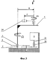
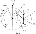
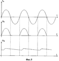
Изобретение поясняется с использованием чертежей, на которых представлено: фиг.1 - общий вид электростанции; фиг.2 - вид А с фиг.1; фиг.3 - кинематическая схема электростанции; фиг.4 - вид Б с фиг.3; и фиг.5 - графики: FY (t)- центробежной силы; Ω4(t) - угловой скорости ведущего звена; Ω22(1) - угловой скорости ротора электрогенератора.The invention is illustrated using the drawings, which show: figure 1 - General view of the power plant; figure 2 is a view a from figure 1; figure 3 is a kinematic diagram of a power plant; 4 is a view B of figure 3; and figure 5 - graphs: F Y (t) - centrifugal force; Ω 4 (t) is the angular velocity of the leading link; Ω 22 (1) - the angular velocity of the rotor of the generator.
Введены следующие цифровые обозначения: 1 - основание, 2 - неподвижная ось, 3 - первая обгонная муфта, 4 - зубчатое колесо, 5 - платформа, 6 - электродвигатель, 7 - вал электродвигателя, 8 - ведущая шестерня, 9 и 10 - ведомые шестерни, 11 и 12 - оси вращения, 13 и 14 - дебалансные массы, 15 - токосъемник, 16 - шестерня, 17 - зубчатое колесо, 18 - ось, 19 - шестерня, 20 - вторая обгонная муфта, 21 - электрогенератор, 22 - вал ротора электрогенератора, 23 - фундамент.The following digital designations are introduced: 1 - base, 2 - fixed axis, 3 - first freewheel, 4 - gear, 5 - platform, 6 - electric motor, 7 - electric motor shaft, 8 - pinion gear, 9 and 10 - driven gears, 11 and 12 - rotation axes, 13 and 14 - unbalanced masses, 15 - current collector, 16 - gear, 17 - gear wheel, 18 - axis, 19 - gear, 20 - second overrunning clutch, 21 - electric generator, 22 - electric generator rotor shaft , 23 - the foundation.
Кроме того, введены буквенные обозначения: Х и Y - координатные оси; Ω - угловая скорость вращения платформы 5 и ведущего зубчатого колеса 4; ω - угловая скорость вращения массы 14; r - радиус вращения массы 14; R - радиус переносного вращения оси 12; F - центробежная сила; FY - проекция центробежной силы F на ось Y; FX - проекция центробежной силы F на ось X. Изогнутые стрелки обозначают направления вращения и момента.In addition, letter designations are introduced: X and Y - coordinate axes; Ω is the angular velocity of rotation of the
Электростанция содержит основание 1, на котором выполнена неподвижная ось 2 с насаженной на нее первой обгонной муфтой 3. Внутреннее кольцо муфты 3 неподвижно, а ее внешнее кольцо может свободно вращаться только в одном направлении. На внешнем кольце муфты 3 закреплен первый узел, включающий рабочее (ведущее) звено, в качестве которого используется зубчатое колесо 4, жестко соединенное с платформой 5, содержащей задающий привод. Задающий привод включает электродвигатель 6, механизм передачи вращения от него к дебалансам, содержащий ось 7 двигателя 6 с насаженной на нее шестерней 8, находящейся в зацеплении с шестернями 9 и 10, на которых выполнены дебалансы 14 и 13. Шестерни 9 и 10 выполнены с возможностью свободного вращения на осях 12 и 11, установленных на платформе 5. Токосъемник 15 предназначен для подвода электропитания к электродвигателю 6. Шестерня 16 и зубчатое 17 установлены на общей оси 18 с возможностью вращения. Кинематическая цепь из зубчатых колес 4, 16 и 17 передает рабочий момент второму узлу. Второй узел содержит ведомую шестерню 19, вторую обгонную муфту 20, вал 22, генератор 21. При этом шестерня 19 соединена с внешним кольцом муфты 20, внутреннее кольцо которой соединено с валом 22 ротора электрогенератора 21, статор которого укреплен неподвижно на основании 1. Муфта 20 передает на вал 22 рабочий момент при увеличении скорости вращения шестерни 19 и размыкает кинематическую цепь - при уменьшении скорости вращения шестерни 19, в соответствии с графиком, представленным на фиг.5.The power plant comprises a
Электростанция работает следующим образом. От источника подают электропитание на электродвигатель 6. Последний набирает обороты до номинальной частоты вращения и раскручивает шестерни 9 и 10 с дебалансными массами 14 и 13 до частоты со. Вращение, например, массы 14 порождает центробежную силу F. Она всегда действует вдоль радиуса r, перпендикулярно оси 12, поэтому начало вектора силы F можно поместить в центре 12 (фиг.4). Ее проекция FY на ось Y изменяется по гармоническому закону:The power plant operates as follows. The power is supplied from the source to the
![]()
![]()
где m - масса 14 (см., например, Яблонский А.А. Курс теоретической механики. Ч. II. Динамика. M., Высшая школа, 1971, стр.142). Проекция силы F на ось Х равна FX. Равнодействующая центробежных сил вдоль оси Х всегда равна нулю, т.к. они взаимно уравновешены симметрично расположенными дебалансами. Составляющая центробежной силы FY создает рабочий момент M относительно оси 2, приложенный к ведущему зубчатому колесу 4 величиной:where m is mass 14 (see, for example, A. Yablonsky, Course in Theoretical Mechanics. Part II. Dynamics. M., Higher School, 1971, p. 142). The projection of the force F on the X axis is equal to F X. The resultant of centrifugal forces along the X axis is always zero, because they are mutually balanced by symmetrically located unbalances. The component of the centrifugal force F Y creates a working moment M relative to the
![]()
![]()
Вектор силы FY - всегда перпендикулярен радиусу R. Одновременно, к зубчатому колесу 4 и к платформе 5 приложен момент трения (механическая нагрузка) Мтр. Момент трения Мтр создает сила трения Fтр, которая всегда перпендикулярна радиусу R, действует вдоль прямой, совпадающей с вектором FY и приложена к оси 12, противоположно последнему. При этом тангенциальная сила Fт, создаваемая двигателем 6 и вращающая дебаланс 14, в свою очередь всегда направлена перпендикулярно к вектору FY. Это означает, что момент Мтр не противодействует вращению вала 7 двигателя 6, за счет чего несколько повышается кпд и происходит стабилизация работы привода устройства в целом.The force vector F Y is always perpendicular to the radius R. At the same time, the friction moment (mechanical load) M tr is applied to the
Следует обратить внимание на то, что центробежная сила относится к силам инерции, а последние являются внешними силами для любой механической системы. Это означает, что рабочий момент М, приложенный к колесу 4, является моментом внешней силы и, в конечном счете, приложен через ось 2 к основанию 1. Поэтому основание 1 должно быть надежно закреплено на фундаменте 23. При использовании способа в устройствах, предназначенных для размещения на транспортных средствах, необходимо устанавливать два одинаковых узла с противоположным направлением рабочих моментов, чтобы взаимно уравновесить их воздействие на транспортное средство.It should be noted that centrifugal force refers to inertial forces, and the latter are external forces for any mechanical system. This means that the working moment M applied to the
Claims (10)
Priority Applications (12)
| Application Number | Priority Date | Filing Date | Title |
|---|---|---|---|
| RU2008105388/11A RU2377458C2 (en) | 2008-02-12 | 2008-02-12 | Operation method of power rotation drive and power plant for its implementation |
| CNU2008201264492U CN201266787Y (en) | 2008-02-12 | 2008-06-27 | power station |
| HRP20130257AT HRP20130257T1 (en) | 2008-02-12 | 2008-10-02 | Method for operating a power rotary actuator and a power plant for carrying out said method |
| US12/867,453 US8866314B2 (en) | 2008-02-12 | 2008-10-02 | Method for operating a power rotary actuator and a power plant for carrying out said method |
| PCT/RU2008/000631 WO2009102232A1 (en) | 2008-02-12 | 2008-10-02 | Method for operating a power rotary actuator and a power plant for carrying out said method |
| ES08872337T ES2402275T3 (en) | 2008-02-12 | 2008-10-02 | Method for operating a rotating power drive element and a power plant for carrying out said method |
| PT88723374T PT2241785E (en) | 2008-02-12 | 2008-10-02 | METHOD FOR OPERATING A ROTARY FEEDING ACTUATOR AND AN ENERGY CENTER FOR CARRYING OUT THE REFERENCE METHOD |
| EP08872337A EP2241785B1 (en) | 2008-02-12 | 2008-10-02 | Method for operating a power rotary actuator and a power plant for carrying out said method |
| SI200830913T SI2241785T1 (en) | 2008-02-12 | 2008-10-02 | Method for operating a power rotary actuator and a power plant for carrying out said method |
| PL08872337T PL2241785T3 (en) | 2008-02-12 | 2008-10-02 | A method of operation of a rotary actuator and an actuator for implementing said method |
| DK08872337.4T DK2241785T3 (en) | 2008-02-12 | 2008-10-02 | A method of operating an electrically rotating actuator and a power unit for carrying out the method |
| CY20131100244T CY1113918T1 (en) | 2008-02-12 | 2013-03-22 | METHOD OF OPERATION OF A MOTION POWER TRANSFER MECHANISM AND INSTALLATION OF FULL EQUIPMENT FOR ITS APPLICATION |
Applications Claiming Priority (1)
| Application Number | Priority Date | Filing Date | Title |
|---|---|---|---|
| RU2008105388/11A RU2377458C2 (en) | 2008-02-12 | 2008-02-12 | Operation method of power rotation drive and power plant for its implementation |
Publications (2)
| Publication Number | Publication Date |
|---|---|
| RU2008105388A RU2008105388A (en) | 2009-08-20 |
| RU2377458C2 true RU2377458C2 (en) | 2009-12-27 |
Family
ID=40833157
Family Applications (1)
| Application Number | Title | Priority Date | Filing Date |
|---|---|---|---|
| RU2008105388/11A RU2377458C2 (en) | 2008-02-12 | 2008-02-12 | Operation method of power rotation drive and power plant for its implementation |
Country Status (12)
| Country | Link |
|---|---|
| US (1) | US8866314B2 (en) |
| EP (1) | EP2241785B1 (en) |
| CN (1) | CN201266787Y (en) |
| CY (1) | CY1113918T1 (en) |
| DK (1) | DK2241785T3 (en) |
| ES (1) | ES2402275T3 (en) |
| HR (1) | HRP20130257T1 (en) |
| PL (1) | PL2241785T3 (en) |
| PT (1) | PT2241785E (en) |
| RU (1) | RU2377458C2 (en) |
| SI (1) | SI2241785T1 (en) |
| WO (1) | WO2009102232A1 (en) |
Cited By (5)
| Publication number | Priority date | Publication date | Assignee | Title |
|---|---|---|---|---|
| RU2481514C1 (en) * | 2011-12-05 | 2013-05-10 | Андрей Викторович Тимофеев | Method of increasing inertia drive of revolution and power drive to this end |
| WO2013074052A1 (en) | 2011-11-18 | 2013-05-23 | Trubyanov Yuriy Valentynovych | Energy generator |
| RU2514958C2 (en) * | 2012-06-28 | 2014-05-10 | Александр Федорович Ежов | Power drive |
| RU2552765C2 (en) * | 2012-12-27 | 2015-06-10 | Эдвид Иванович Линевич | Rotation power drive |
| RU2604908C2 (en) * | 2015-03-18 | 2016-12-20 | Эдвид Иванович Линевич | Vehicle |
Families Citing this family (8)
| Publication number | Priority date | Publication date | Assignee | Title |
|---|---|---|---|---|
| TW201304364A (en) * | 2011-07-11 | 2013-01-16 | Sheng-Chuang Zhang | Electric power generation device |
| US9190886B2 (en) | 2012-04-27 | 2015-11-17 | Sole Power, Llc | Foot-powered energy generator |
| US8970054B2 (en) * | 2012-04-27 | 2015-03-03 | Sole Power, Llc | Foot-powered energy harvesting mechanisms for insoles and shoes |
| EP2781269A1 (en) * | 2013-03-20 | 2014-09-24 | Eurodrill GmbH | Vibration generator, especially for a construction machine |
| CN103912463B (en) * | 2014-04-09 | 2017-01-25 | 保定金荣海重能环保科技有限公司 | Energy-conservation environment-friendly all-wheel-drive power machine |
| WO2018069584A1 (en) * | 2017-03-28 | 2018-04-19 | Maurice Granger | Oscillating mechanism with simultaneous cross centrifugal forces, machine and method for using same |
| WO2018217796A1 (en) * | 2017-05-22 | 2018-11-29 | Resonant Systems, Inc. | Efficient haptic accuator |
| EP4729771A1 (en) | 2024-10-17 | 2026-04-22 | Stefan Ciolacu | Method and device for the sequential conversion of centrifugal and centripetal forces into mechanical work |
Citations (1)
| Publication number | Priority date | Publication date | Assignee | Title |
|---|---|---|---|---|
| GB146783A (en) * | 1918-11-25 | 1920-07-15 | Jean Edouard Andreau | Improvements in or relating to epicyclic transmission gear |
Family Cites Families (23)
| Publication number | Priority date | Publication date | Assignee | Title |
|---|---|---|---|---|
| US3210579A (en) * | 1961-12-18 | 1965-10-05 | Yaskawa Denki Seisakusho Kk | Apparatus for generating vibration |
| FR1576528A (en) * | 1968-05-17 | 1969-08-01 | ||
| FR1588205A (en) | 1968-06-12 | 1970-04-10 | ||
| US3558901A (en) * | 1969-02-24 | 1971-01-26 | Charles J Jacobus | Standby power system |
| US3860844A (en) * | 1972-02-28 | 1975-01-14 | Suisse Horlogerie | Low friction miniature gear drive for transmitting small forces |
| SU417301A1 (en) | 1972-05-22 | 1974-02-28 | ||
| US3960036A (en) | 1975-03-26 | 1976-06-01 | Discojet Corporation | Torque converter |
| DE2612035A1 (en) | 1976-03-22 | 1977-09-29 | Kayser Herold Uwe | Mechanical torque converter with epicyclic gear - has unbalanced weights attached to planet wheels to regulate transmitted torque |
| NZ188087A (en) * | 1977-08-19 | 1980-11-28 | Agrowplow Pty Ltd | Vibrating device |
| US4307629A (en) * | 1978-07-31 | 1981-12-29 | Moller Paul S | Torque converter |
| US4446418A (en) * | 1979-12-06 | 1984-05-01 | Richardson Royest L | Generator and drive system |
| SU1061856A1 (en) | 1981-08-25 | 1983-12-23 | Ленинградское высшее военное инженерное строительное Краснознаменное училище им.генерала армии А.Н.Комаровского | Vibration drive |
| US4498357A (en) | 1982-09-22 | 1985-02-12 | George Makarov | Mass accelerator and power converter unit |
| GB2234037A (en) * | 1989-05-30 | 1991-01-23 | Kramatorsk Ind I | Unbalance vibrator |
| JP3594982B2 (en) * | 1993-03-29 | 2004-12-02 | 三菱電機株式会社 | Electric blower |
| US6998723B2 (en) * | 2002-08-06 | 2006-02-14 | Carl Cheung Tung Kong | Electrical generating system having a magnetic coupling |
| US6700263B1 (en) * | 2002-08-06 | 2004-03-02 | Carl Cheung Tung Kong | Electrical generating system having a magnetic coupling |
| US6946748B2 (en) * | 2003-12-03 | 2005-09-20 | Love Kevin R | Inertia wheel coupled with a leverage transmission |
| WO2006096845A2 (en) * | 2005-03-08 | 2006-09-14 | Manning John B | Electric motor starting device |
| JP4914060B2 (en) * | 2005-11-30 | 2012-04-11 | 株式会社ブイエスディー | Flywheel generator |
| US20080143302A1 (en) * | 2006-12-18 | 2008-06-19 | Regen Technologies, Inc. | Electrical power generation system |
| US7556077B2 (en) * | 2006-12-28 | 2009-07-07 | Tex Year Industries Inc. | Speed-change transmission mechanism for laminator or the like |
| JP2008187758A (en) * | 2007-01-26 | 2008-08-14 | Vsd:Kk | Flywheel generator |
-
2008
- 2008-02-12 RU RU2008105388/11A patent/RU2377458C2/en not_active IP Right Cessation
- 2008-06-27 CN CNU2008201264492U patent/CN201266787Y/en not_active Expired - Lifetime
- 2008-10-02 WO PCT/RU2008/000631 patent/WO2009102232A1/en not_active Ceased
- 2008-10-02 PL PL08872337T patent/PL2241785T3/en unknown
- 2008-10-02 ES ES08872337T patent/ES2402275T3/en active Active
- 2008-10-02 US US12/867,453 patent/US8866314B2/en active Active
- 2008-10-02 DK DK08872337.4T patent/DK2241785T3/en active
- 2008-10-02 EP EP08872337A patent/EP2241785B1/en not_active Not-in-force
- 2008-10-02 PT PT88723374T patent/PT2241785E/en unknown
- 2008-10-02 SI SI200830913T patent/SI2241785T1/en unknown
- 2008-10-02 HR HRP20130257AT patent/HRP20130257T1/en unknown
-
2013
- 2013-03-22 CY CY20131100244T patent/CY1113918T1/en unknown
Patent Citations (1)
| Publication number | Priority date | Publication date | Assignee | Title |
|---|---|---|---|---|
| GB146783A (en) * | 1918-11-25 | 1920-07-15 | Jean Edouard Andreau | Improvements in or relating to epicyclic transmission gear |
Cited By (5)
| Publication number | Priority date | Publication date | Assignee | Title |
|---|---|---|---|---|
| WO2013074052A1 (en) | 2011-11-18 | 2013-05-23 | Trubyanov Yuriy Valentynovych | Energy generator |
| RU2481514C1 (en) * | 2011-12-05 | 2013-05-10 | Андрей Викторович Тимофеев | Method of increasing inertia drive of revolution and power drive to this end |
| RU2514958C2 (en) * | 2012-06-28 | 2014-05-10 | Александр Федорович Ежов | Power drive |
| RU2552765C2 (en) * | 2012-12-27 | 2015-06-10 | Эдвид Иванович Линевич | Rotation power drive |
| RU2604908C2 (en) * | 2015-03-18 | 2016-12-20 | Эдвид Иванович Линевич | Vehicle |
Also Published As
| Publication number | Publication date |
|---|---|
| PT2241785E (en) | 2013-04-02 |
| SI2241785T1 (en) | 2013-06-28 |
| US20110057457A1 (en) | 2011-03-10 |
| RU2008105388A (en) | 2009-08-20 |
| US8866314B2 (en) | 2014-10-21 |
| ES2402275T3 (en) | 2013-04-30 |
| EP2241785A1 (en) | 2010-10-20 |
| EP2241785A4 (en) | 2011-09-14 |
| DK2241785T3 (en) | 2013-04-08 |
| WO2009102232A1 (en) | 2009-08-20 |
| CY1113918T1 (en) | 2016-07-27 |
| EP2241785B1 (en) | 2012-12-26 |
| PL2241785T3 (en) | 2013-07-31 |
| HRP20130257T1 (en) | 2013-05-31 |
| CN201266787Y (en) | 2009-07-01 |
Similar Documents
| Publication | Publication Date | Title |
|---|---|---|
| RU2377458C2 (en) | Operation method of power rotation drive and power plant for its implementation | |
| KR20140093278A (en) | Energy generator | |
| SK20793A3 (en) | Multiplying gear of kinetic energy with driving unit | |
| JP7678489B1 (en) | Thrust generation method | |
| CN202644355U (en) | Road roller vibrating drum capable of shifting modes of circular vibration, oscillation or compound vibration | |
| US12504058B2 (en) | Device for increasing the efficiency of any rotary power generating system with progressive variation | |
| RU2552765C2 (en) | Rotation power drive | |
| RU2514958C2 (en) | Power drive | |
| RU2182533C2 (en) | Vibration type nut driver | |
| RU205136U1 (en) | POWER VIBRATION DRIVE | |
| EP4729771A1 (en) | Method and device for the sequential conversion of centrifugal and centripetal forces into mechanical work | |
| RU2844500C2 (en) | Gearbox | |
| RU2481514C1 (en) | Method of increasing inertia drive of revolution and power drive to this end | |
| RU2182259C2 (en) | Device for making engine-flywheel | |
| RU2081741C1 (en) | Vibration nut-setter | |
| JPH03275180A (en) | Centrifugal force generator for which nonuniform speed gear is used | |
| RU104228U1 (en) | SHOCK ACTUATOR WITH KINETIC ENERGY RECOVERY | |
| RU2076241C1 (en) | Inertia propelling device | |
| SU795927A1 (en) | Electric vibration nut wrench | |
| US20070137420A1 (en) | Method and device for self-contained inertial vehicular propulsion | |
| SU483149A1 (en) | Vibration exciter | |
| SU1196037A1 (en) | Internal vibration exciter of moment | |
| RU2171929C2 (en) | Automatic infinitely variable mechanical transmission | |
| SU1592160A1 (en) | VIBRATION MIXER | |
| RU84929U1 (en) | AUTOMATIC ROTATING TORQUE TRANSFORMER |
Legal Events
| Date | Code | Title | Description |
|---|---|---|---|
| MM4A | The patent is invalid due to non-payment of fees |
Effective date: 20110213 |
|
| NF4A | Reinstatement of patent |
Effective date: 20120410 |
|
| MM4A | The patent is invalid due to non-payment of fees |
Effective date: 20180213 |