RU2373103C1 - Device to fasten and separate submarine surfacing buoy with conducting rope - Google Patents
Device to fasten and separate submarine surfacing buoy with conducting rope Download PDFInfo
- Publication number
- RU2373103C1 RU2373103C1 RU2008113555/11A RU2008113555A RU2373103C1 RU 2373103 C1 RU2373103 C1 RU 2373103C1 RU 2008113555/11 A RU2008113555/11 A RU 2008113555/11A RU 2008113555 A RU2008113555 A RU 2008113555A RU 2373103 C1 RU2373103 C1 RU 2373103C1
- Authority
- RU
- Russia
- Prior art keywords
- buoy
- cable
- housing
- basket
- cover
- Prior art date
Links
Images


Landscapes
- Laying Of Electric Cables Or Lines Outside (AREA)
Abstract
Description
Изобретение относится к области подводного кораблестроения, а именно к устройствам крепления и отделения всплывающего аварийного буя с соединительным трос-кабелем, и предназначено для использования на подводных технических средствах (ПТС) для хранения и постановки привязных буев, например, аварийно-спасательных для подводных лодок.The invention relates to the field of underwater shipbuilding, and in particular to devices for fastening and separating a pop-up emergency buoy with a connecting cable-cable, and is intended for use on underwater technical equipment (PTS) for storing and stowing buoys, for example, rescue boats for submarines.
Известно устройство «Надуваемый сигнальный буй», предназначенное для запуска надуваемого буя с погруженной подводной лодки или другого ПТС (патент Англии №1169273, МПК: В63В 21/52, опубликован 05.11.69 г.). Это устройство содержит выгородку в корпусе с закрывающимся люком, механизм принудительного выталкивания буя, включающий цилиндр с поршнем, который приводится в движение пиротехническим зарядом (ПТЗ), находящимся в цилиндре, механизм сбрасывания крышки люка, устройства сигнализации. Подрыв ПТЗ производится по сигналу, поступающему с поста управления.A device is known “Inflated signal buoy", designed to launch an inflatable buoy from a submerged submarine or other PTS (England patent No. 1169273, IPC: B63B 21/52, published 05.11.69). This device contains a baffle in the case with a closing hatch, a mechanism for forcing buoys, including a cylinder with a piston, which is driven by a pyrotechnic charge (PTZ) located in the cylinder, a mechanism for dropping the manhole cover, and an alarm device. Undermining the PTZ is carried out by a signal from the control station.
Также известно «Устройство для вывода буксируемой антенны из прочного корпуса подводной лодки» (патент США №3245373, НКИ: 114-235, МПК: B63G 8/38, В63В 21/00, заявл. 25.06.1964 г.), обеспечивающее вывод буя за борт.Also known is a "Device for withdrawing a towed antenna from a robust hull of a submarine" (US patent No. 3245373, NKI: 114-235, IPC:
Это устройство содержит цилиндр, вмонтированный в прочный корпус (ПК) ПТС с наружной и внутренней герметичными крышками, внутри которого размещен буй, при этом во внутренней крышке имеется отверстие с сальником для прохождения гибкого металлического трос-кабеля, связанного с буем, а наружная крышка открывается при помощи гидравлического или механического привода известной конструкции, имеется также устройство принудительного выталкивания буя.This device contains a cylinder mounted in a durable case (PC) PTS with outer and inner airtight covers, inside which there is a buoy, while in the inner cover there is an opening with an oil seal for the passage of a flexible metal cable-cable connected with the buoy, and the outer cover opens by means of a hydraulic or mechanical drive of a known design, there is also a device for forcing buoy.
Недостатком этого устройства является низкая эксплуатационная надежность из-за необходимости герметизировать наружную и внутреннюю крышки, вмонтированные в прочный корпус подводной лодки, а также наличие привода для открывания тяжелой наружной крышки. При ненадежной герметизации указанных элементов возможно поступление забортной воды в корпус подводной лодки или заклинивание привода при открывании крышки.The disadvantage of this device is the low operational reliability due to the need to seal the outer and inner covers mounted in a sturdy hull of the submarine, as well as the presence of a drive to open the heavy outer cover. In case of unreliable sealing of these elements, outboard water can enter the hull of the submarine or jam the drive when the lid is opened.
Также известно «Устройство крепления и отделения аварийного буя подводной лодки» по патенту США №3933109, НКИ: 114-16.5, которое содержит корпус (выгородку), открытый сверху и вписанный в верхнюю часть корпуса судна с запорными устройствами, снабженными захватами, и с механизмом крепления-отдачи буя и обрубания кабеля с двумя пиротехническими патронами (пиропатронами). Эта выгородка расположена в надстройке судна, в нижней ее части размещены 2 пиротехнических патрона (пиропатрона), которые управляются вручную или автоматически. При срабатывании пиропатронов буй, обладающий плавучестью, отпускается. Буй снабжен дополнительными элементами плавучести, выполненными в виде баллонов из пористого материала. Запорные устройства удерживают буй при помощи захватов, взаимодействующих с зубьями, установленными на буе. Пиротехнический патрон и кабель связывают буй с пультом субмарины.It is also known "The device for mounting and separating an emergency submarine buoy" according to US patent No. 3933109, NKI: 114-16.5, which contains a hull (baffle), open at the top and inscribed in the upper part of the hull with locking devices equipped with grippers, and with a mechanism fastening-recoil of the buoy and chopping off the cable with two pyrotechnic cartridges (squibs). This baffle is located in the superstructure of the vessel, in its lower part there are 2 pyrotechnic cartridges (squib), which are controlled manually or automatically. When the squibs are triggered, the buoy with buoyancy is released. The buoy is equipped with additional buoyancy elements made in the form of cylinders of porous material. Locking devices hold the buoy by means of grippers interacting with the teeth mounted on the buoy. A pyrotechnic cartridge and cable connect the buoy to the submarine console.
В этом устройстве не обеспечен надежный выход всплывающего буя из камеры (выгородки) при воздействии встречного гидродинамического потока, прижимающего буй к стенкам выгородки, а также при значительном аварийном крене или дифференте ПТС, так как буй выходит из выгородки только за счет плавучести. Задержка выхода буя из камеры может привести к его разрушению при провале ПТС предельной глубины погружения.This device does not provide reliable exit of the pop-up buoy from the chamber (baffle) when exposed to an oncoming hydrodynamic flow, pressing the buoy against the walls of the baffle, as well as with a significant emergency roll or PTS differential, since the buoy leaves the baffle only due to buoyancy. The delay in the exit of the buoy from the chamber can lead to its destruction in case of failure of the TCP of the maximum immersion depth.
Это устройство недостаточно надежно и долговечно в эксплуатации ввиду того, что элементы запорного устройства (пружины и др.) находятся в морской воде и подвержены коррозии. Структура пружинных сталей мелкозернистая, что обуславливает их более интенсивную коррозию по сравнению с корпусными сталями.This device is not reliable enough and durable in operation due to the fact that the elements of the locking device (springs, etc.) are in sea water and are subject to corrosion. The structure of spring steels is fine-grained, which leads to their more intense corrosion compared to case steels.
Это устройство небезопасно в эксплуатации, так как раскрепление буя производится пиропатронами, пороховые газы которых разрезают несущую часть корпуса буя и кабель. В случае несанкционированного срабатывания пиропатронов при обслуживании буя возможны травмы обслуживающего персонала от действия ударной волны пороховых газов.This device is unsafe in operation, since the buoy is unfastened by squibs, the powder gases of which cut the carrying part of the buoy body and cable. In the event of an unauthorized actuation of the squib during maintenance of the buoy, injuries to service personnel from the action of the shock wave of powder gases are possible.
Также известно «Устройство крепления и отделения всплывающего буя на подводном техническом средстве» по патенту России №2214340, МПК 7: В63В 22/08, которое содержит полуоткрытый корпус, вписанный в верхнюю часть подводного технического средства, механизм принудительного выталкивания буя, запорное устройство, выполненное в виде поворотных щитов, установленных сверху снаружи корпуса и имеющих встроенные блоки плавучести из легковесного прочного заполнителя, механизм крепления-отдачи буя и обрубания соединительного кабеля (отсекатель) с пиротехническим приводом.It is also known "The device for mounting and separating a pop-up buoy on an underwater technical means" according to Russian patent No. 2214340, IPC 7: ВВВ 22/08, which contains a half-open housing inscribed in the upper part of the underwater technical means, a mechanism for forcing buoys, a locking device made in the form of rotary shields installed on top of the outside of the hull and having built-in buoyancy units from a lightweight durable aggregate, a fastening-recoil mechanism for the buoy and chopping off of the connecting cable (cut-off) with a pie technical drive.
Устройство по патенту России №2214340 выбрано в качестве наиболее близкого аналога.The device according to the patent of Russia No. 2214340 is selected as the closest analogue.
В известном устройстве недостаточна плавучесть буя, так блок плавучести из легковесного прочного заполнителя встроен только в щиты запорного устройства, закрывающие корпус, для их легкого открывания и не обеспечивает металлическому бую необходимую плавучесть при его всплытии из глубины к поверхности моря совместно с вытравливаемым трос-кабелем, кроме того, в известном устройстве трос-кабель, соединяющий буй с ПТС, отсекается одновременно с отдачей буя, что снижает тактические возможности всплывшего на поверхность моря аварийно-спасательного буя из-за исключения постоянной передачи информации с аварийного подводного технического средства через подсоединенный к бую трос-кабель.In the known device, buoy buoys are insufficient, so a buoyancy unit from a lightweight durable aggregate is integrated only in shutter shields that cover the housing for their easy opening and does not provide the metal buoy with the necessary buoyancy when it emerges from depth to the sea surface together with an etched cable-cable, in addition, in the known device, the cable-cable connecting the buoy with the PTS is cut off simultaneously with the return of the buoy, which reduces the tactical capabilities of the rescued to the surface of the sea buoy due to the exclusion of the constant transmission of information from an emergency underwater technical means through a cable connected to the buoy.
В известном устройстве недостаточна надежность крепления буя ввиду того, что он закреплен в нижней части только за опорную втулку, при этом запорные устройства не удерживают плотно буй за боковые поверхности. При таком креплении встречный гидродинамический поток и инерционные силы, возникающие при движении ПТС, воздействуют на буй, раскачивая его относительно нижней опорной втулки и нижнего опорного кольца.In the known device, the buoy's mounting reliability is insufficient due to the fact that it is fixed in the lower part only to the support sleeve, while the locking devices do not hold the buoy tightly on the side surfaces. With this fastening, the oncoming hydrodynamic flow and the inertial forces arising from the movement of the PTS act on the buoy, swinging it relative to the lower support sleeve and the lower support ring.
В известном устройстве отсутствует сигнализация об отдаче буя, что снижает эксплуатационные характеристики аварийного устройства.In the known device there is no alarm about the return of the buoy, which reduces the operational characteristics of the emergency device.
Задача изобретения заключается в повышении тактических возможностей устройства, а также его эксплуатационных характеристик.The objective of the invention is to increase the tactical capabilities of the device, as well as its operational characteristics.
Задача решена тем, что в известном устройстве, содержащем полуоткрытый корпус с днищем с кольцевым упором, запорным устройством и блоком плавучести, механизм крепления-отдачи буя с пиротехническим приводом, подвижным поршнем и штоком, установленный в съемном корпусном блоке на днище полуоткрытого корпуса отсекатель трос-кабеля и механизм принудительного выталкивания буя, согласно изобретению полуоткрытый корпус выполнен в виде усеченного конуса, обращенного широким основанием кверху, запорное устройство выполнено в виде крышки, установленной на буе, блок плавучести закреплен между крышкой и днищем вокруг буя, а трос-кабель пропущен через днище корпуса и уложен в корзину, при этом корзина снабжена двумя взаимодействующими между собой крышками, выполненными с возможностью поворота и выпуска трос-кабеля, которые снабжены блоками плавучести, а одна из крышек подпружинена и выполнена с возможностью взаимодействия с буем посредством толкателя, который пропущен через днище корпуса и шарнирно соединен с одной стороны с буем, а с другой - с крышкой корзины.The problem is solved in that in the known device comprising a half-open housing with a bottom with an annular stop, a locking device and a buoyancy unit, a fastening-recoil mechanism of the buoy with a pyrotechnic drive, a movable piston and a rod mounted in a removable housing block on the bottom of the half-open housing is a cable cutter cable and the mechanism for forcing buoy, according to the invention, the half-open housing is made in the form of a truncated cone, facing a wide base up, the locking device is made in the form of a cover, mouth Mounted on the buoy, the buoyancy unit is fixed between the lid and the bottom around the buoy, and the cable cable is passed through the bottom of the hull and laid in the basket, while the basket is equipped with two interacting covers that are designed to rotate and release the cable, which are equipped with blocks buoyancy, and one of the lids is spring-loaded and configured to interact with the buoy by means of a pusher, which is passed through the bottom of the hull and is pivotally connected on one side to the buoy, and on the other to the basket lid.
Кроме того, на крышке, на днище и на конусной поверхности корпуса выполнены соответствующие упругие прокладки, к которым прижат блок плавучести, выполненный из легковесного прочного заполнителя, удельная плотность которого меньше, чем удельная плотность воды.In addition, on the lid, on the bottom and on the conical surface of the body, corresponding elastic gaskets are made to which the buoyancy unit is pressed, made of a lightweight durable aggregate, whose specific gravity is less than the specific gravity of water.
Кроме того, механизм крепления-отдачи буя снабжен сигнализатором перемещения штока, закрепленным на подвижном поршне с возможностью взаимодействия с электрическим преобразователем перемещений, закрепленным в съемном корпусном блоке с возможностью регулировки его положения.In addition, the buoy fastening-recoil mechanism is equipped with a rod displacement detector mounted on a movable piston to interact with an electric displacement transducer fixed in a removable housing unit with the possibility of adjusting its position.
Кроме того, кольцевой упор, установленный на днище корпуса, выполнен в виде клюза с возможностью пропускания через него трос-кабеля.In addition, the annular emphasis mounted on the bottom of the housing is made in the form of a clus with the possibility of passing through it a cable cable.
Кроме того, на днище корпуса выполнено отверстие для прохождения толкателя, а на буе закреплен упор с шаровой опорной поверхностью для шарнирного соединения с толкателем.In addition, a hole for the passage of the pusher is made on the bottom of the housing, and a stop with a ball bearing surface is fixed on the buoy for swiveling with the pusher.
Кроме того, толкатель выполнен с возможностью регулирования его установочной длины.In addition, the pusher is configured to adjust its installation length.
Кроме того, крышка корзины подпружинена посредством рычажного механизма, закрепленного на корзине.In addition, the basket lid is spring-loaded by means of a lever mechanism mounted on the basket.
Кроме того, отсекатель и корзина установлены возле места крепления трос-кабеля на подводном техническом средстве.In addition, the cutter and the basket are installed near the place of attachment of the cable cable on the underwater technical equipment.
Встраивание в устройство блока плавучести, охватывающего буй, закрепленного между крышкой и днищем буя, выполненного из легковесного прочного заполнителя с боковой конусной поверхностью, плотно упирающейся в боковую расширяющуюся кверху конусную поверхность корпуса устройства отдачи, позволяет повысить плавучесть буя, что обеспечивает возможность его всплытия к поверхности моря совместно с вытравливаемым трос-кабелем с глубоко погруженного аварийного ПТС, а также более надежно зафиксировать буй в корпусе при его хранении за счет исключения возможности раскачивания буя относительно нижней опорной втулки и нижнего кольцевого упора при воздействии встречного гидродинамического потока и боковых инерционных сил, возникающих при движении ПТС.Integration into the device of a buoyancy unit, covering the buoy, fixed between the cover and the bottom of the buoy, made of lightweight durable aggregate with a lateral conical surface that abuts against the lateral conical surface of the recoil device, which increases the buoyancy, which makes it possible to float to the surface of the sea together with the etched cable from a deeply immersed emergency vehicle, as well as more securely fix the buoy in the hull during its storage due to for prison possible rocking of the buoy relative to the lower bearing sleeve and the lower annular abutment under the action of the hydrodynamic flow and counter-lateral inertial forces due to the motion of the TCP.
Введение в устройство корзины для хранения трос-кабеля с поворотными крышками, со встроенными в них блоками плавучести из легковесного прочного заполнителя, одна из которых подпружинена и шарнирно связана через толкатель с регулировочной установочной длиной с упором с шаровой опорной поверхностью, закрепленным на буе, позволяет надежно хранить и при этом закрепить от вытравливания трос-кабель на ПТС, обеспечить надежное открывание крышек корзины, а также дополнительное выталкивающее усилие для выхода буя из корпуса и вытравливание трос-кабеля с глубоко погруженного аварийного ПТС, а выполнение кольцевого упора, расположенного в нижней части корпуса, в виде клюза для прохождения трос-кабеля позволит обеспечить надежное вытравливание трос-кабеля при значительном крене и дифференте аварийного ПТС без дополнительных его перегибов.The introduction to the device of a basket for storing a cable cable with pivoting covers, with built-in buoyancy units made of lightweight strong aggregate, one of which is spring-loaded and pivotally connected via a pusher with an adjustable installation length with a stop with a ball bearing surface mounted on the buoy, allows reliable to store and at the same time secure the cable-cable to the PTS from etching, to ensure reliable opening of the basket lids, as well as an additional buoyancy force for the buoy to exit the body and to etch the a cable with a deeply submerged emergency TCP, and perform the stop ring, located in the lower housing part in the form of a cable fairlead for passing cable will ensure a reliable etching wire cable with a substantial heel and trim emergency TCP without additional its inflections.
Закрепление на подвижном поршне механизма крепления-отдачи буя сигнализатора перемещения штока с электрическим преобразователем, закрепленным с возможностью регулировки его положения винтом в съемном корпусном блоке, позволяет улучшить эксплуатационные характеристики устройства за счет передачи сигнала на ПТС о фактической отдаче аварийного буя.Fastening on the movable piston of the fastening-recoil mechanism of the buoy of the rod movement detector with an electric converter fixed with the possibility of adjusting its position by a screw in a removable housing unit allows to improve the operational characteristics of the device by transmitting a signal to the TCP about the actual return of the emergency buoy.
Установка отсекателя с пиротехническим приводом, обрубающего трос-кабель, за корзиной для хранения трос-кабеля, в районе закрепления конца трос-кабеля на ПТС, также позволяет улучшить эксплуатационные характеристики устройства за счет обеспечения обрубания трос-кабеля при погружении аварийного ПТС за предельную глубину с целью исключения затопления всплывшего с трос-кабелем буя, а до этого момента связь буя с ПТС будет поддерживаться, что улучшает его тактические возможности.The installation of a cutter with a pyrotechnic drive, chopping off the cable cable, behind the basket for storing the cable cable, in the area of fastening the end of the cable cable to the PTS, also allows to improve the operational characteristics of the device by ensuring the cutting of the cable cable when the emergency PTS is immersed to the maximum depth with the purpose of eliminating the flooding of a buoy that emerged with a cable-cable, and until that moment, the buoy’s connection with the TCP will be maintained, which improves its tactical capabilities.
Устройство пояснено чертежами, где:The device is illustrated by drawings, where:
на фиг.1 представлен продольный разрез по корпусу устройства;figure 1 presents a longitudinal section through the housing of the device;
на фиг.2 представлен поперечный разрез по корпусу устройства;figure 2 presents a cross section through the housing of the device;
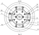
на фиг.3 представлен разрез А-А с фиг.2 - расположение пружинных механизмов принудительного выталкивания буя, а также опорной втулки и упора с шаровой опорной поверхностью на корпусе буя;figure 3 presents a section aa from figure 2 - the location of the spring mechanisms for pushing the buoy, as well as the support sleeve and stop with a ball bearing surface on the body of the buoy;
на фиг.4 показан разрез Б-Б с фиг.1- механизм крепления - отдачи буя;figure 4 shows a section bB with figure 1 - mounting mechanism - recoil buoy;
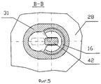
на фиг.5 показан разрез В-В с фиг.4 - паз в ступице с опорной втулкой и штоком механизма крепления - отдачи буя;figure 5 shows a section bb In figure 4 - a groove in the hub with a support sleeve and the rod of the mounting mechanism - return buoy;
на фиг.6 показан разрез Г-Г с фиг.4 - поперечный разрез механизма крепления-отдачи буя.in Fig.6 shows a section GG with Fig.4 is a transverse section of the mechanism of fastening-recoil buoy.
на фиг.7 показан разрез Д-Д с фиг.2 - механизм принудительного выталкивания буя;Fig.7 shows a section DD from Fig.2 - a mechanism for forcing buoy;
на фиг.8 показан разрез Е-Е с фиг.2 - корзина с крышками для хранения трос-кабеля,;in Fig.8 shows a section EE of Fig.2 - a basket with covers for storing a cable cable;
на фиг.9 показан разрез Ж-Ж с фиг.8 - отсекатель трос-кабеля;in Fig.9 shows a section FJ with Fig.8 - cut-off cable;
Устройство крепления и отделения всплывающего буя 1 с трос-кабелем 2 на ПТС (см. фиг.1) имеет корпус 3, установленный заподлицо с надстройкой 4 в междубортном пространстве ПТС. Корпус 3 имеет форму полого усеченного конуса, обращенного широким основанием кверху. В корпус 3 встроен блок плавучести 5, выполненный из легковесного прочного заполнителя с удельной плотностью меньшей, чем удельная плотность воды, который охватывает буй 1 и закреплен стяжками 6 между крышкой - запором 7, предохраняющей блок плавучести 5 от действия ледовой нагрузки при всплытии ПТС в Северных широтах, и днищем 8 буя 1 через прокладку 9. Блок плавучести 5 упирается в кольцевую упругую прокладку 10, закрепленную на внутренней боковой расширяющейся кверху конусной поверхности корпуса 3. Устройство включает также закрепленный на корпусе 3 механизм 11 принудительного выталкивания буя 1, опорное кольцо 12, жестко закрепленное на буе 1, кольцевой упор 13, который выполнен в виде клюза и закреплен в нижней части корпуса 3, механизм 14 крепления-отдачи буя 1 с сигнализатором срабатывания, установленный в корпусе 3, упор 15 с шаровой опорной поверхностью и опорную втулку 16 с боковым пазом, закрепленными на днище 8 буя 1, толкатель 17 с регулируемой установочной длинной, корзину 18 для укладки и хранения в ней трос-кабеля 2, снабженную поворотными крышками 19 и 20 (см. фиг.1, 2).The device for fastening and separating the pop-up buoy 1 with the cable-
Крышка 20 подпружинена рычажным механизмом 21 и взаимодействует с крышкой 19 посредством упора 22 (см. фиг.1, 2, 8). Толкатель 17 шарнирно связан с одной стороны с упором 15 с шаровой опорной поверхностью, а с другой - с крышкой 20 корзины 18. Крышки 19 и 20 закрывают корзину 18, в которой уложен трос-кабель 2, один конец которого закреплен на буе 1, а другой закреплен на ПТС. В крышки 19 и 20 встроен блок плавучести 23 из легковесного прочного заполнителя, обеспечивающий легкость их поворота и открывания в подводном положении ПТС. Рядом с корзиной 18 на ПТС, в районе крепления трос-кабеля 2 установлен механизм обрубания трос-кабеля - отсекатель 24 с пиротехническим приводом 25 (см. фиг..2, 9).The
Корпус 3 (см. фиг.1 и фиг.2) предназначен для хранения буя 1. Конусная часть 26 корпуса 3 вверху заканчивается жестко закрепленным опорным фланцем 27, за который производится крепление корпуса 3 заподлицо с надстройкой 4 ПТС. Конусная часть 26 корпуса 3 внизу имеет днище 28 с центральным отверстием. На днище 28 смонтирован кольцевой упор 13, выполненный в виде клюза для прохождения трос-кабеля 2.The housing 3 (see Fig. 1 and Fig. 2) is designed to store the buoy 1. The
На боковых наружных поверхностях корпуса 3 симметрично относительно буя 1 смонтированы рычажные механизмы 11 принудительного выталкивания буя 1, которые имеют поворотные рычаги 29, проходящие через вырезы в корпусе 3 и взаимодействующие через ролики 30 с днищем 8 буя 1. (см. фиг.1, 2, 3).On the lateral outer surfaces of the
На днище 28 корпуса 3 жестко закреплена ступица 31 (см. фиг.1, 5), на которой смонтирован механизм 14 крепления-отдачи буя 1 с сигнализатором срабатывания. В днище 28 также выполнено отверстие для прохождения толкателя 17.On the bottom 28 of the
Механизм 11 принудительного выталкивания буя 1 (см. фиг.1, 2, 3 и 7) предназначен для выталкивания буя 1 после его отдачи из внутренней полости корпуса 3 устройства. Механизм 11 принудительного выталкивания буя 1 содержит: поворотные трубы 32, которые расположены симметрично относительно буя 1, например, с четырех сторон от него. Каждая поворотная труба 32 имеет по два жестко закрепленных на ней рычага 29, герметично закрыта с двух сторон крышками 33, имеющими уплотнительные кольца 34. Крышки 33 вместе с трубой 32 установлены на неподвижном валике 35 с возможностью поворота относительно последнего (см. фиг.7). Валик 35 расположен внутри трубы и закреплен неподвижно в опорных кронштейнах 36, установленных на корпусе 26. На валик 35 накручена силовая пружина кручения (торсион) 37, один конец которой закреплен на неподвижном валике 35, а другой - на поворотной трубе 32 с рычагами 29, которая поворачивается относительно валика 35 при выталкивании буя 1. Внутренняя герметичная полость трубы 32 заполнена антикоррозионной смазкой для исключения коррозии пружины 37 в случае протечек морской воды во внутреннюю полость трубы 32.The
Пружинный рычажный механизм 21 привода открывания крышки 20 корзины 18 по конструкции аналогичен механизму 11 принудительного выталкивания буя 1 и отличается тем, что вместо роликов 30 к концам рычагов, аналогичных рычагам 29, прикреплена крышка 20 (см. фиг.8).The
Механизм 14 крепления-отдачи буя 1 с сигнализатором срабатывания (см. фиг.1, 2, 4, 5, 6,) предназначен для закрепления буя 1 в походном положении ПТС, отдачи буя 1 при его выпуске и сигнализации срабатывания привода отдачи буя 1.The
Механизм 14 крепления-отдачи буя 1 с сигнализатором срабатывания пиротехнического привода включает закрепленный на днище 28 кольцевой упор 13, выполненный в виде клюза для прохождения трос-кабеля 2 с жестко закрепленной на днище 28 ступицей 31, съемный корпусной блок 38 с направляющими, установленными в пазах ступицы 31, зафиксированный штифтом 39 с пружиной 40 (см. фиг.6). В съемном корпусном блоке 38 установлен поршень 41, ось которого перпендикулярна оси ступицы 31, а в средней части поршня 41 соосно ступице 31 вмонтирован шток 42 с головкой, взаимодействующей с буртиком опорной втулки 16 буя 1, которая размещается в ступице 31, когда буй 1 находится в корпусе 3 устройства. В ступице 31, втулке 16 и съемном корпусном блоке 38 выполнен совмещенный паз, для продольного перемещения в нем штока 42. В съемном корпусном блоке 38 по одну сторону поршня 41 установлен сигнализатор 43 магнитный бесконтактный, взаимодействующий с электрическим преобразователем перемещений 44, закрепленным с возможностью регулировки его положения винтом 45 на корпусном блоке 38 (см. фиг.4).The fastening-
По другую сторону поршня 41 герметично установлен цилиндр 46 со встроенным пиротехническим зарядом 47 и герметичным кабельным вводом 48. Крепление цилиндра 46 в съемном корпусном блоке 38 выполнено соосно с поршнем 41 с помощью кольцевого паза и закладного сухаря 49, установленного в соответствующий паз, выполненный в съемном корпусном блоке 38. Закладной сухарь 49 жестко зафиксирован болтом 50. Герметизация цилиндра 46 выполнена с помощью резиновых уплотнительных колец 51. Поршень 41 зафиксирован относительно съемного корпусного блока 38 предохранительным штифтом 52.On the other side of the
Отсекатель 24 с пиротехническим приводом 25 (см. фиг.8, 9) обрубания трос-кабеля 2 по конструкции аналогичен механизму 14 крепления-отдачи буя 1 с сигнализатором срабатывания пиротехнического привода и содержит поршень 53, одна сторона которого герметично установлена в цилиндр 54 со встроенным пиротехническим зарядом (пиропатроном) 55 и герметичным кабельным вводом 56, а другая сторона поршня 53 имеет режущую кромку, взаимодействующую с трос-кабелем 2, при срабатывании отсекателя 24. Трос-кабель 2 вмонтирован в паз съемной крышки 57 отсекателя 24 и закреплен на ПТС. Для исключения самопроизвольного перемещения поршень 53 неподвижно закреплен в цилиндре 54 предохранительным штифтом 58.The shut-off
Работа устройства крепления - отделения всплывающего буя 1 с трос-кабелем 2 на ПТС происходит в двух режимах:The operation of the attachment device - separation of the pop-up buoy 1 with the cable-
а) крепление буя 1 с трос-кабелем 2 «по-походному» (исходное);a) fastening the buoy 1 with a cable-
б) в режиме отделения буя 1 с трос-кабелем 2 с ПТС по сигналу на отдачу;b) in the mode of separation of the buoy 1 with a cable-
В режиме крепления «по-походному» (исходное состояние) элементы заявляемого устройства находятся в следующем положении.In the mounting mode "marching" (initial state), the elements of the claimed device are in the following position.
Буй 1 находится внутри корпуса 3, блок плавучести 5, охватывающий буй 1 и закрепленный между крышкой 7, днищем 8 и боковой конусной частью 26 корпуса 3, расширяющейся кверху, опирается в упругую прокладку 10. Рычаги 29 находятся в нижнем положении и ролики 30 поджаты к днищу 8 буя 1 усилием от действия взведенных силовых пружин 37 кручения рычажного механизма 11 принудительного выталкивания. Опорное кольцо 12 буя 1 прижато к кольцевому упору 13, втулка 16, жестко закрепленная на днище 8 и имеющая боковой паз, вставлена в ступицу 31, головка штока 42 располагается внутри втулки 16 и сцеплена с ее внутренним буртиком, удерживая втулку 16 от подъема вместе с буем 1 (см. фиг.1, 2, 4, 6).The buoy 1 is located inside the
Трос-кабель 2 проходит через кольцевой упор 13 (см. фиг.1, 2), прикреплен одним концом к бую 1, а другой его конец зажат крышками 19 и 20 с блоками плавучести 23, уложен в корзине 18, выпущен из нее, вмонтирован в отсекатель 24, расположенный за корзиной 18, и закреплен на ПТС.The cable-
Толкатель 17, выполненный с регулируемой установочной длиной для обеспечения сборки устройства, одним концом через шарнир упирается в упор 15 с шаровой опорной поверхностью, жестко закрепленный на днище 8, а другим концом шарнирно закреплен на крышке 20, подпружиненной рычажным механизмом 21, и удерживает ее от открывания.The pusher 17, made with an adjustable installation length to ensure assembly of the device, at one end abuts against a
В механизме 14 крепления-отдачи буя 1 поршень 41 со штоком 42 и цилиндр 46 закреплены в корпусном блоке 38 с помощью кольцевого паза и закладного сухаря 49, установленного в соответствующий паз, выполненный в съемном корпусном блоке 38. Закладной сухарь 49 жестко зафиксирован болтом 50 (см. фиг.4).In the fastening-
Поршень 41 неподвижно закреплен в корпусе 38 предохранительным штифтом 52, а корпус 38 с направляющими неподвижно зафиксирован в ступице 31 с помощью штифта 39, удерживаемого пружиной 40. Пиротехнический заряд 47 размещен внутри герметичного цилиндра 46 и соединен с электрическим проводом кабельного ввода 48. На торце поршня 41 закреплен сигнализатор 43, например магнитный бесконтактный, взаимодействующий с электрическим преобразователем перемещений 44, закрепленным с возможностью регулировки его положения для настройки магнитного контакта винтом 45 на корпусном блоке 38.The
При креплении буя 1 «по-походному» конструкция устройства предусматривает также возможность обслуживания и съема буя 1 из устройства без срабатывания пиротехнического заряда 47. Для этого вручную при нажатии на фиксатор 39 сжимается пружина 40 (см. фиг.6,) и корпусной блок 38 перемещают вдоль направляющих ступицы 31 до выхода головки штока 42 из втулки 16, в результате чего буй 1 возможно выдвинуть из корпуса 26, при этом под действием пружин рычажного механизма 21 открывается крышка 20 и вручную открывается крышка 19 для осмотра трос-кабеля 2. Установка устройства в исходное положение производится в обратном порядке.When mounting the buoy 1 "in a marching" design, the device also provides for the possibility of servicing and removing the buoy 1 from the device without triggering a
В режиме отделения буя 1 с трос-кабелем 2 заявляемое устройство, погруженное в воду, работает следующим образом.In the separation mode of the buoy 1 with
По команде с пульта управления (на чертеже не показано) подают электрический сигнал на пиротехнический заряд 47 механизма 14 крепления-отдачи буя 1 (см. фиг.4), который срабатывает и создает значительное избыточное давление газов в герметичном цилиндре 46, которое воздействует на поршень 41 и перемещает его вместе с закрепленным на нем штоком 42 с головкой, разрушая предохранительный штифт 52, и перемещает сигнализатор 43, который через электрический преобразователь 44 передает сигнал на ПТС об отдаче буя 1. После перемещения штока 42 с головкой до упора в ступицу 31 втулка 16 освобождается и выходит из ступицы 31, при этом плавучий буй 1 начинает всплывать вверх за счет блока плавучести 5, а также от воздействия на него механизма принудительного выталкивания 11 посредством рычагов 29 с роликами 30, прижатыми к днищу 8 буя 1. Рычаги 29 поворачиваются вместе с трубами 32 за счет раскручивания силовых пружин 37 (см. фиг.7). Кроме того, толкатель 17 за счет открывания подпружиненной крышки 20 с блоком плавучести 23 также принудительно выталкивает буй 1. При открывании крышки 20 открывается и крышка 19, также снабженная блоком плавучести 23, что освобождает трос-кабель 2, который вытравливается через опорное кольцо (клюз) 13 из корзины 18 за счет положительной плавучести буя 1, всплывающего к поверхности моря для функционирования.On command from the control panel (not shown in the drawing), an electrical signal is supplied to the
В случае если аварийное ПТС затапливается на глубину, большую предельной и большую, чем длина трос-кабеля 2, по сигналу датчика забортного давления воды (на чертеже не показан) подается электрический сигнал на пиротехнический заряд 55 (см. фиг.9), который срабатывает и создает значительное избыточное давление газов в герметичном цилиндре 54, которое воздействует на поршень 53 и перемещает его, срезая предохранительный штифт 58 и обрубая острой кромкой поршня 53 трос-кабель 2, в результате чего буй 1 отделяется от ПТС и работает на поверхности моря в автономном режиме, сохраняя последнюю информацию.If the emergency vehicle is flooded to a depth greater than the limit and greater than the length of the
Цикл работы заявленного устройства заканчивается.The cycle of operation of the claimed device ends.
Предлагаемая конструкция устройства крепления и отделения всплывающего буя с трос-кабелем на ПТС позволяет повысить тактические возможности устройства, повысить надежность закрепления буя и улучшить эксплуатационные характеристики устройства:The proposed design of the device for fastening and separating a pop-up buoy with a cable cable at the PTS allows to increase the tactical capabilities of the device, increase the reliability of the buoy fastening and improve the operational characteristics of the device:
за счет крепления к бую между верхней крышкой, предохраняющей блок плавучести от действия ледовой нагрузки при всплытии ПТС в Северных широтах, и днищем охватывающего его блока плавучести из легковесного прочного заполнителя с удельной плотностью меньшей, чем удельная плотность воды повышается плавучесть буя;due to the attachment to the buoy between the top cover, which protects the buoyancy unit from ice loads during the emergence of the TCP in the Northern latitudes, and the bottom of the buoyancy block covering it from a lightweight durable aggregate with a specific gravity less than the specific gravity of the water, the buoyancy increases;
за счет выполнения блока плавучести, охватывающего буй, с боковой конусной поверхностью, плотно упирающейся в боковую расширяющуюся в верхней части конусную поверхность корпуса устройства отдачи через упругую прокладку, компенсирующую зазоры и люфты, обеспечивается при хранении более надежное закрепление буя и исключение его раскачивания относительно нижней опорной втулки и нижнего опорного кольца при воздействии встречного гидродинамического потока и боковых инерционных сил, возникающих при движении ПТС;due to the implementation of the buoyancy unit, covering the buoy, with a lateral conical surface that abuts against the lateral conical surface of the recoil device, expanding in the upper part, through an elastic gasket that compensates for gaps and backlash, more reliable fastening of the buoy is ensured during storage and the rocking against the lower supporting the sleeve and the lower support ring when exposed to the oncoming hydrodynamic flow and lateral inertial forces arising from the movement of the TCP;
за счет введения корзины для хранения трос-кабеля с поворотными крышками обеспечивается надежное хранение и закрепление трос-кабеля на ПТС и обеспечивается возможность его вытравливания при всплытии буя к поверхности моря с закрепленным концом трос-кабеля с глубоко погруженного аварийного ПТС совместно с вытравливаемым трос-кабелем, обеспечивая постоянную передачу информации с аварийного подводного технического средства через подсоединенный к бую трос-кабель;due to the introduction of a cable storage basket with rotary covers, reliable storage and fastening of the cable cable to the PTS is ensured and it can be etched when the buoy ascends to the sea surface with a fixed cable end from a deeply immersed emergency PTS together with the etched cable , providing a constant transmission of information from an emergency underwater technical equipment through a cable cable connected to the buoy;
за счет выполнения кольцевого упора, расположенного в нижней части корпуса устройства, в виде клюза для прохождения трос-кабеля, жестко закрепленного к бую, обеспечивается надежное вытравливание трос-кабеля при значительных крене и дифференте аварийного ПТС без дополнительных его перегибов;due to the execution of the ring stop located in the lower part of the device’s body, in the form of a clus for the passage of the cable-cable rigidly fixed to the buoy, reliable etching of the cable-cable is provided with significant roll and differential of the emergency vehicle without additional bends;
за счет выполнения поворотной крышки над корзиной хранения трос-кабеля, подпружиненной рычажным механизмом, а также встраивания в нее блока плавучести из легковесного прочного заполнителя с удельной плотностью меньшей, чем удельная плотность воды, и введение толкателя с регулируемой установочной длиной, шарнирно прикрепленного к поворотной крышке и упирающегося в упор с шаровой опорной поверхностью, закрепленный на буе, через отверстие в днище корпуса устройства обеспечивается дополнительное выталкивающее усилие и обеспечивается более надежный выход буя из корпуса устройства при его отдаче;due to the implementation of the rotary cover over the storage basket of the cable-spring loaded by a lever mechanism, as well as the integration of a buoyancy unit from it of a lightweight durable aggregate with a specific gravity lower than the specific gravity of water, and the introduction of a pusher with an adjustable installation length pivotally attached to the rotary cover and abutting against a stop with a ball bearing surface, mounted on a buoy, an additional pushing force is provided through an opening in the bottom of the device body and is provided more a more reliable exit of the buoy from the device’s body when it is returned;
за счет монтажа на подвижном поршне механизма крепления-отдачи буя с пиротехническим приводом сигнализатора перемещения штока и электрического преобразователя, закрепленного с возможностью регулировки его положения винтом на корпусе механизма крепления-отдачи буя, обеспечивается передача сигнала на ПТС об отдаче буя и повышаются эксплуатационные характеристики устройства;due to the mounting on the movable piston of the buoy fastening-recoil mechanism with a pyrotechnic drive of the rod movement indicator and an electric converter fixed with the ability to adjust its position with a screw on the buoy fastening-recoil mechanism housing, the signal is transmitted to the PTS about the buoy return and the device’s performance characteristics are improved;
за счет установки отсекателя с пиротехническим приводом, обрубающего трос-кабель, за корзиной, возле места крепления трос-кабеля на ПТС обеспечивается обрубание трос-кабеля при затапливании ПТС на глубину, превышающую предельную и большую, чем длина трос-кабеля, при этом исключается затапливание буя и сохраняется его последняя информация.by installing a cutter with a pyrotechnic drive that cuts off the cable cable, behind the basket, near the cable cable mounting point on the PTS, the cable cable is cut off when the PTS is flooded to a depth exceeding the maximum and greater than the length of the cable cable, while flooding is excluded buoy and its latest information is saved.
Claims (8)
Priority Applications (1)
| Application Number | Priority Date | Filing Date | Title |
|---|---|---|---|
| RU2008113555/11A RU2373103C1 (en) | 2008-04-07 | 2008-04-07 | Device to fasten and separate submarine surfacing buoy with conducting rope |
Applications Claiming Priority (1)
| Application Number | Priority Date | Filing Date | Title |
|---|---|---|---|
| RU2008113555/11A RU2373103C1 (en) | 2008-04-07 | 2008-04-07 | Device to fasten and separate submarine surfacing buoy with conducting rope |
Publications (1)
| Publication Number | Publication Date |
|---|---|
| RU2373103C1 true RU2373103C1 (en) | 2009-11-20 |
Family
ID=41477816
Family Applications (1)
| Application Number | Title | Priority Date | Filing Date |
|---|---|---|---|
| RU2008113555/11A RU2373103C1 (en) | 2008-04-07 | 2008-04-07 | Device to fasten and separate submarine surfacing buoy with conducting rope |
Country Status (1)
| Country | Link |
|---|---|
| RU (1) | RU2373103C1 (en) |
Cited By (10)
| Publication number | Priority date | Publication date | Assignee | Title |
|---|---|---|---|---|
| RU2482026C2 (en) * | 2011-07-25 | 2013-05-20 | Открытое акционерное общество Научно-производственное объединение "Искра" | Recoverable info tank |
| RU2685498C1 (en) * | 2018-08-13 | 2019-04-18 | Федеральное государственное бюджетное учреждение науки Институт проблем морских технологий Дальневосточного отделения Российской академии наук (ИПМТ ДВО РАН) | Device for capture of floating halyard by autonomous unmanned underwater vehicle |
| CN110395357A (en) * | 2019-05-21 | 2019-11-01 | 中国船舶重工集团公司第七一九研究所 | A kind of buoy storage release device |
| CN110588921A (en) * | 2019-09-25 | 2019-12-20 | 博雅工道(北京)机器人科技有限公司 | Floating ball device and underwater robot |
| CN110588896A (en) * | 2019-10-22 | 2019-12-20 | 上海普适导航科技股份有限公司 | Release locator |
| RU2723998C1 (en) * | 2020-02-03 | 2020-06-18 | Российская Федерация, от имени которой выступает ФОНД ПЕРСПЕКТИВНЫХ ИССЛЕДОВАНИЙ | Device for attachment and separation of small object (buoy) from high-speed underwater object |
| RU2735194C1 (en) * | 2020-03-02 | 2020-10-28 | Российская Федерация, от имени которой выступает Государственная корпорация по атомной энергии "Росатом" (Госкорпорация "Росатом") | Device for remote suspension at specified depth in water of self-contained floating instrument part |
| RU2755692C1 (en) * | 2021-02-09 | 2021-09-20 | Павел Анатольевич Прилепко | Acoustic disconnector |
| CN115140241A (en) * | 2022-07-12 | 2022-10-04 | 海洋石油工程股份有限公司 | Automatic tripping device for underwater mooring rope and anchor chain |
| CN118494702A (en) * | 2024-07-17 | 2024-08-16 | 威海德创海洋科技有限公司 | Semi-submersible wind power ship |
Citations (4)
| Publication number | Priority date | Publication date | Assignee | Title |
|---|---|---|---|---|
| US2375299A (en) * | 1943-05-19 | 1945-05-08 | Hartnett Joseph Robert | Apparatus for escape from submerged vessels |
| US4497632A (en) * | 1983-04-06 | 1985-02-05 | Rocket Research Company | Inflatable buoy |
| SU1729905A1 (en) * | 1990-02-01 | 1992-04-30 | Научно-исследовательский институт прикладной математики и механики | Sunk object lifting device |
| RU2214340C2 (en) * | 2001-12-17 | 2003-10-20 | Федеральное государственное унитарное предприятие Санкт-Петербургское морское бюро машиностроения "Малахит" | Device for securing and releasing surfacing buoy on submersible technical facility |
-
2008
- 2008-04-07 RU RU2008113555/11A patent/RU2373103C1/en active
Patent Citations (4)
| Publication number | Priority date | Publication date | Assignee | Title |
|---|---|---|---|---|
| US2375299A (en) * | 1943-05-19 | 1945-05-08 | Hartnett Joseph Robert | Apparatus for escape from submerged vessels |
| US4497632A (en) * | 1983-04-06 | 1985-02-05 | Rocket Research Company | Inflatable buoy |
| SU1729905A1 (en) * | 1990-02-01 | 1992-04-30 | Научно-исследовательский институт прикладной математики и механики | Sunk object lifting device |
| RU2214340C2 (en) * | 2001-12-17 | 2003-10-20 | Федеральное государственное унитарное предприятие Санкт-Петербургское морское бюро машиностроения "Малахит" | Device for securing and releasing surfacing buoy on submersible technical facility |
Cited By (10)
| Publication number | Priority date | Publication date | Assignee | Title |
|---|---|---|---|---|
| RU2482026C2 (en) * | 2011-07-25 | 2013-05-20 | Открытое акционерное общество Научно-производственное объединение "Искра" | Recoverable info tank |
| RU2685498C1 (en) * | 2018-08-13 | 2019-04-18 | Федеральное государственное бюджетное учреждение науки Институт проблем морских технологий Дальневосточного отделения Российской академии наук (ИПМТ ДВО РАН) | Device for capture of floating halyard by autonomous unmanned underwater vehicle |
| CN110395357A (en) * | 2019-05-21 | 2019-11-01 | 中国船舶重工集团公司第七一九研究所 | A kind of buoy storage release device |
| CN110588921A (en) * | 2019-09-25 | 2019-12-20 | 博雅工道(北京)机器人科技有限公司 | Floating ball device and underwater robot |
| CN110588896A (en) * | 2019-10-22 | 2019-12-20 | 上海普适导航科技股份有限公司 | Release locator |
| RU2723998C1 (en) * | 2020-02-03 | 2020-06-18 | Российская Федерация, от имени которой выступает ФОНД ПЕРСПЕКТИВНЫХ ИССЛЕДОВАНИЙ | Device for attachment and separation of small object (buoy) from high-speed underwater object |
| RU2735194C1 (en) * | 2020-03-02 | 2020-10-28 | Российская Федерация, от имени которой выступает Государственная корпорация по атомной энергии "Росатом" (Госкорпорация "Росатом") | Device for remote suspension at specified depth in water of self-contained floating instrument part |
| RU2755692C1 (en) * | 2021-02-09 | 2021-09-20 | Павел Анатольевич Прилепко | Acoustic disconnector |
| CN115140241A (en) * | 2022-07-12 | 2022-10-04 | 海洋石油工程股份有限公司 | Automatic tripping device for underwater mooring rope and anchor chain |
| CN118494702A (en) * | 2024-07-17 | 2024-08-16 | 威海德创海洋科技有限公司 | Semi-submersible wind power ship |
Similar Documents
| Publication | Publication Date | Title |
|---|---|---|
| RU2373103C1 (en) | Device to fasten and separate submarine surfacing buoy with conducting rope | |
| EP2138395B1 (en) | Assembly for deploying a payload from a submarine | |
| US6021731A (en) | Ballast system for underwater vehicle | |
| US9126662B2 (en) | Release apparatus for a load on a device and underwater device | |
| US20080127877A1 (en) | Pre-positioning deployment system | |
| IL191114A (en) | Appliance for lowering and tracking an underwater vessel | |
| RU2214340C2 (en) | Device for securing and releasing surfacing buoy on submersible technical facility | |
| RU2719491C1 (en) | Device for underwater launch and reception of autonomous unmanned underwater vehicle | |
| RU2042570C1 (en) | Method and device for breaking ice by means of submersible water craft | |
| US5619951A (en) | System for launching a lifeboat | |
| US20220266956A1 (en) | Parachute sea anchor | |
| RU2186707C1 (en) | Device for storage, anchorage and reception of buoy with floating line on underwater facility | |
| RU2309871C2 (en) | Two-module submarine with emergency and rescue system and operational-tactical complex | |
| KR20130115506A (en) | Underwater vehicle | |
| RU2174088C1 (en) | System for collective rescue of submarine tanker crew in an emergency at considerable list and trim | |
| US4313381A (en) | Mooring system | |
| US5033354A (en) | Deep operating monitor and destruct device | |
| RU149901U1 (en) | RESCUE-RESCUE CAMERA FOR USE WHEN OPERATING SUBMARINE UNDER UNDER CONDITIONS | |
| WO2010133788A1 (en) | Method and device for the remote-controlled deployment of systems or means that can be used for the protection of harbours and ships, for marine safety or for the discrete marking of underwater objects | |
| RU2708067C1 (en) | Double-housing lifeboat of closed type for evacuation and rescue of personnel and crew of sea objects in ice conditions | |
| RU2707477C2 (en) | Device for separation of floating chamber with underwater technical equipment | |
| FR2701102A1 (en) | Independent device for launching an object in a submarine environment | |
| RU2680538C2 (en) | Rescue hatch of underwater technical means | |
| RU2214342C1 (en) | Container for storage and release of radio buoy on submersible technical facility |