RU2318640C2 - Mode of laser welding for one pass of t-shaped mount of metallic elements - Google Patents
Mode of laser welding for one pass of t-shaped mount of metallic elements Download PDFInfo
- Publication number
- RU2318640C2 RU2318640C2 RU2003132652/02A RU2003132652A RU2318640C2 RU 2318640 C2 RU2318640 C2 RU 2318640C2 RU 2003132652/02 A RU2003132652/02 A RU 2003132652/02A RU 2003132652 A RU2003132652 A RU 2003132652A RU 2318640 C2 RU2318640 C2 RU 2318640C2
- Authority
- RU
- Russia
- Prior art keywords
- welding
- head
- laser welding
- legs
- shaped assembly
- Prior art date
Links
Images


Classifications
-
- B—PERFORMING OPERATIONS; TRANSPORTING
- B23—MACHINE TOOLS; METAL-WORKING NOT OTHERWISE PROVIDED FOR
- B23K—SOLDERING OR UNSOLDERING; WELDING; CLADDING OR PLATING BY SOLDERING OR WELDING; CUTTING BY APPLYING HEAT LOCALLY, e.g. FLAME CUTTING; WORKING BY LASER BEAM
- B23K26/00—Working by laser beam, e.g. welding, cutting or boring
- B23K26/08—Devices involving relative movement between laser beam and workpiece
- B23K26/10—Devices involving relative movement between laser beam and workpiece using a fixed support, i.e. involving moving the laser beam
-
- B—PERFORMING OPERATIONS; TRANSPORTING
- B23—MACHINE TOOLS; METAL-WORKING NOT OTHERWISE PROVIDED FOR
- B23K—SOLDERING OR UNSOLDERING; WELDING; CLADDING OR PLATING BY SOLDERING OR WELDING; CUTTING BY APPLYING HEAT LOCALLY, e.g. FLAME CUTTING; WORKING BY LASER BEAM
- B23K26/00—Working by laser beam, e.g. welding, cutting or boring
- B23K26/02—Positioning or observing the workpiece, e.g. with respect to the point of impact; Aligning, aiming or focusing the laser beam
- B23K26/06—Shaping the laser beam, e.g. by masks or multi-focusing
- B23K26/067—Dividing the beam into multiple beams, e.g. multifocusing
-
- B—PERFORMING OPERATIONS; TRANSPORTING
- B23—MACHINE TOOLS; METAL-WORKING NOT OTHERWISE PROVIDED FOR
- B23K—SOLDERING OR UNSOLDERING; WELDING; CLADDING OR PLATING BY SOLDERING OR WELDING; CUTTING BY APPLYING HEAT LOCALLY, e.g. FLAME CUTTING; WORKING BY LASER BEAM
- B23K26/00—Working by laser beam, e.g. welding, cutting or boring
- B23K26/02—Positioning or observing the workpiece, e.g. with respect to the point of impact; Aligning, aiming or focusing the laser beam
- B23K26/06—Shaping the laser beam, e.g. by masks or multi-focusing
- B23K26/0604—Shaping the laser beam, e.g. by masks or multi-focusing by a combination of beams
- B23K26/0608—Shaping the laser beam, e.g. by masks or multi-focusing by a combination of beams in the same heat affected zone [HAZ]
-
- B—PERFORMING OPERATIONS; TRANSPORTING
- B23—MACHINE TOOLS; METAL-WORKING NOT OTHERWISE PROVIDED FOR
- B23K—SOLDERING OR UNSOLDERING; WELDING; CLADDING OR PLATING BY SOLDERING OR WELDING; CUTTING BY APPLYING HEAT LOCALLY, e.g. FLAME CUTTING; WORKING BY LASER BEAM
- B23K26/00—Working by laser beam, e.g. welding, cutting or boring
- B23K26/20—Bonding
- B23K26/21—Bonding by welding
- B23K26/24—Seam welding
- B23K26/242—Fillet welding, i.e. involving a weld of substantially triangular cross section joining two parts
-
- B—PERFORMING OPERATIONS; TRANSPORTING
- B23—MACHINE TOOLS; METAL-WORKING NOT OTHERWISE PROVIDED FOR
- B23K—SOLDERING OR UNSOLDERING; WELDING; CLADDING OR PLATING BY SOLDERING OR WELDING; CUTTING BY APPLYING HEAT LOCALLY, e.g. FLAME CUTTING; WORKING BY LASER BEAM
- B23K33/00—Specially-profiled edge portions of workpieces for making soldering or welding connections; Filling the seams formed thereby
-
- B—PERFORMING OPERATIONS; TRANSPORTING
- B23—MACHINE TOOLS; METAL-WORKING NOT OTHERWISE PROVIDED FOR
- B23K—SOLDERING OR UNSOLDERING; WELDING; CLADDING OR PLATING BY SOLDERING OR WELDING; CUTTING BY APPLYING HEAT LOCALLY, e.g. FLAME CUTTING; WORKING BY LASER BEAM
- B23K2101/00—Articles made by soldering, welding or cutting
- B23K2101/04—Tubular or hollow articles
Abstract
Description
Область техники, к которой относится изобретениеFIELD OF THE INVENTION
Изобретение относится к постоянному скреплению узла из двух или трех металлических элементов в форме Т, доступного только с одной наружной поверхности. Он используется, в частности, для соединения тонкого, закрытого и разделенного кожуха, такого как лопатка, размещенная в канале с выходной стороны вентилятора в турбореактивном двигателе.The invention relates to the permanent fastening of a node of two or three metal elements in the form of T, accessible from only one outer surface. It is used, in particular, to connect a thin, closed and split casing, such as a blade, located in the channel on the outlet side of the fan in a turbojet engine.
Уровень техники и связанные с этим проблемыBackground and Related Problems
Функцией этого типа лопатки является повышение жесткости структуры турбореактивного двигателя, в частности, за счет создания соединения между двумя коаксиальными кольцевыми оболочками и, возможно, для направления или отклонения потока холодного воздуха, циркулирующего в вентиляторном канале. Эти лопатки являются металлическими ребрами, предпочтительно состоящими из полого кожуха, внутри которого расположены элементы жесткости. Эти кожухи трудно изготавливать и необходимо несколько операций, в частности, для изготовления первичных элементов и для изготовления узла и скрепления так, чтобы были правильными размеры кожуха.The function of this type of blade is to increase the rigidity of the structure of a turbojet engine, in particular by creating a connection between two coaxial annular shells and, possibly, to direct or reject the flow of cold air circulating in the fan duct. These blades are metal ribs, preferably consisting of a hollow casing, within which stiffeners are located. These casings are difficult to manufacture and several operations are necessary, in particular for the manufacture of primary elements and for the manufacture of the assembly and fastening so that the dimensions of the casing are correct.
Как показано на фиг.1, в патенте FR 2705603 раскрыт способ лазерной сварки для сборки двух металлических элементов в форме Т. Этот способ показывает средство для изготовления разделенных кожухов посредством скрепления элементов снаружи кожуха. Лазерный луч 8А, 8В зажигают последовательно два раза под наклонным углом, при этом путь пересекает наружную поверхность 1В элемента 1 с образованием головки Т-образного узла. Две оси лазерного луча 8А и 8В при сварке касаются двух верхних углов 2С элемента 2, выполняющего роль ножки Т. Сварочное устройство расположено снаружи кожуха, другими словами, со стороны наружной поверхности 1В головки Т-образного узла.As shown in FIG. 1, patent FR 2705603 discloses a laser welding method for assembling two metal elements in the form of T. This method shows a means for manufacturing divided shells by fastening the elements outside the shell. The
Поэтому этот способ использует два последовательных прохода лазерного луча, каждый из которых вызывает последовательные деформации.Therefore, this method uses two consecutive passes of the laser beam, each of which causes successive deformations.
Можно добавить, что этот тип сборки требует дополнительного материала в виде присадочной проволоки для предотвращения дефектов формы после сварки. Это относится, в частности, к шероховатости и к различным выемкам и подрезам. Кроме того, затраты на инструмент являются относительно большими, поскольку элементы необходимо постоянно удерживать неподвижно относительно друг друга и необходимо использовать разматывающее устройство для присадочной проволоки. Наконец, существенным является то, что во время сварки необходимо управлять положением проволоки.It can be added that this type of assembly requires additional material in the form of filler wire to prevent shape defects after welding. This applies in particular to roughness and to various notches and undercuts. In addition, the cost of the tool is relatively large, since the elements must be constantly held motionless relative to each other and it is necessary to use an unwinding device for the filler wire. Finally, it is essential that the position of the wire be controlled during welding.
Поэтому, целью изобретения является преодоление этих недостатков.Therefore, the aim of the invention is to overcome these disadvantages.
Сущность изобретенияSUMMARY OF THE INVENTION
Основной задачей изобретения является создание способа лазерной сварки для узла из металлических элементов, расположенных в форме Т, при этом ножка Т-образного узла образована пластиной с параллельными поверхностями, причем узел является доступным со стороны головки Т-образного узла через наружную поверхность, при этом способ содержит следующие стадии:The main objective of the invention is to provide a laser welding method for a node of metal elements arranged in the form of a T, the leg of the T-shaped node is formed by a plate with parallel surfaces, the node being accessible from the side of the head of the T-shaped node through the outer surface, the method contains the following stages:
- сборки Т-образного узла из элементов, смежных друг с другом,- Assembly of a T-shaped assembly of elements adjacent to each other,
- лазерной сварки узла через наружную поверхность головки Т-образного узла с помощью двух сварочных швов.- laser welding of the assembly through the outer surface of the head of the T-shaped assembly using two welding seams.
Согласно изобретению два сварочных шва выполняются одновременно и являются параллельными друг другу и перпендикулярными наружной поверхности головки Т-образного узла, так что каждая из двух осей сварки является касательной к одной из поверхностей пластины, образующей ножку Т-образного узла.According to the invention, two welds are performed simultaneously and are parallel to each other and perpendicular to the outer surface of the head of the T-shaped assembly, so that each of the two welding axes is tangent to one of the surfaces of the plate forming the leg of the T-shaped assembly.
В предпочтительном варианте выполнения изобретения два сварочных шва выполняются одновременно с помощью двухфокусной сварочной головки.In a preferred embodiment of the invention, two welds are performed simultaneously using a two-focus welding head.
В первом варианте выполнения узла с использованием способа сварки согласно изобретению пластина ножки Т снабжена лапками заданной длины и толщины, и узел содержит второй элемент, образующий головку Т-образного узла с прорезями, имеющими длину и толщину, соответствующими размерам лапок на пластине ножки Т-образного узла.In the first embodiment of the assembly using the welding method according to the invention, the leg plate T is provided with legs of a predetermined length and thickness, and the assembly comprises a second element forming the head of the T-shaped assembly with slots having length and thickness corresponding to the sizes of the legs on the plate of the T-leg node.
В этом случае предпочтительно, если высота Н лапок слегка больше, чем толщина второго элемента узла, образующего головку Т-образного узла.In this case, it is preferable if the height H of the legs is slightly larger than the thickness of the second element of the assembly forming the head of the T-shaped assembly.
Во втором варианте выполнения Т-образного узла с использованием способа сварки согласно изобретению головка Т-образного узла образована двумя пластинами, перпендикулярными пластине ножки Т-образного узла и находящимися своими кромками в контакте с пластиной, образующей ножку.In a second embodiment of the T-shaped assembly using the welding method according to the invention, the head of the T-shaped assembly is formed by two plates perpendicular to the leg plate of the T-shaped assembly and being in contact with the leg-forming plate.
Краткое описание чертежейBrief Description of the Drawings
Для лучшего понимания изобретения и его технических характеристик ниже приводится описание двух вариантов выполнения изобретения со ссылками на чертежи, на которых изображено:For a better understanding of the invention and its technical characteristics, the following is a description of two embodiments of the invention with reference to the drawings, which depict:
фиг.1 - разрез крепления с использованием способа сварки согласно уровню техники, описание которого приведено выше;figure 1 - section of the mount using the welding method according to the prior art, the description of which is given above;
фиг.2 - первая стадия изготовления узла согласно первому варианту выполнения изобретения, в разнесенной изометрической проекции;figure 2 - the first stage of manufacture of the node according to the first embodiment of the invention, in an exploded isometric view;
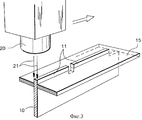
фиг.3 - узел согласно фиг.2, во время стадии сварки, в изометрической проекции;figure 3 - node according to figure 2, during the welding stage, in isometric view;
фиг.4 - узел согласно фиг.2 и 3, в готовом виде;figure 4 - the node according to figure 2 and 3, in finished form;
фиг.5 - второй узел, подлежащий сварке с использованием способа сварки согласно изобретению, в изометрической проекции.5 is a second node to be welded using the welding method according to the invention, in isometric view.
Подробное описание двух вариантов выполнения изобретенияDetailed description of two embodiments of the invention
Первый узелFirst knot
Как показано на фиг.2, первый узел, который можно сваривать с использованием способа сварки, согласно изобретению состоит из двух элементов: ножки 10 Т-образного узла и головки 15 Т-образного узла. Ножка 10 является прямоугольной пластиной заданной толщины с лапками 11 заданной длины, расположенными на заданном расстоянии друг от друга. В соответствии с этим прорези 16 образованы в головке 15 с длиной и шириной, соответствующими лапкам 11 ножки 10. Как показано на фиг.3, можно легко понять, что сборка состоит во вставлении лапок 11 ножки 10 в прорези 16 в головке 15.As shown in FIG. 2, the first assembly that can be welded using the welding method according to the invention consists of two elements:
Лазерная сварочная головка 20 расположена вертикально над лапками 11 ножки Т-образного узла. Эта лазерная сварочная головка 20 является двухфокусной, другими словами, она может излучать два лазерных луча 21, параллельных друг другу. Лазерная сварочная головка 20 отрегулирована так, что два лазерных луча 21 расположены на расстоянии, равном заданной толщине ножки 10. Другими словами, каждый из двух лазерных лучей проходит по касательной к поверхности ножки 10.The
Лапки 11 на ножке 10 и прорези 16 в головке 15 вырезаются с помощью лазерного резания, однако можно использовать также другие способы резания.The
Поэтому сварку с обеих сторон верхнего участка ножки 10 вдоль и между лапками 11 выполняют за один проход посредством продольного перемещения лазерной сварочной головки 20.Therefore, welding on both sides of the upper portion of the
Высота лапок 11 слегка больше толщины головки 15, так что они слегка выступают из нее. Как показано на фиг.4, после завершения сварки эти лапки 11, которые являются присадочным металлом, преобразуются в небольшие выступы 12. Высота сварочного шва увеличивается после сварки при увеличении высоты лапок 11 перед сваркой.The height of the
Второй узелSecond knot
На фиг.5 показан второй узел, который можно использовать для образования Т-образного с использованием лазерного сварочного соединения. Снова используется ножка 30, но без лапок. Два участка, 35D и 35G, расположены в контакте с ножкой 30 и вблизи ее верхнего участка. Они закреплены на ней на одной из кромок и поэтому перпендикулярно выступают из нее. Они также находятся на одной линии друг с другом.Figure 5 shows a second assembly that can be used to form a T-joint using a laser welding joint.
Можно использовать двухфокусную сварку, как указывалось выше применительно к предыдущему узлу, точно тем же образом, при этом каждая из двух осей двух лазерных лучей 21 параллельна вертикальной поверхности ножки 30, при этом сварочный шов выполняется по всей длине узла.Two-focus welding can be used, as mentioned above with respect to the previous node, in exactly the same way, while each of the two axes of two
Главное преимущество изобретения состоит в том, что сварку выполняют за один проход без необходимости применения присадочной проволоки. В результате получают сварочный шов без каких-либо дефектов формы, и минимизируется опасность деформации узла во время сварки.The main advantage of the invention is that welding is performed in one pass without the need for filler wire. As a result, a weld is obtained without any shape defects, and the risk of knot deformation during welding is minimized.
Claims (5)
Applications Claiming Priority (2)
| Application Number | Priority Date | Filing Date | Title |
|---|---|---|---|
| FR0213914A FR2846898B1 (en) | 2002-11-07 | 2002-11-07 | METHOD FOR LASER WELDING IN ONE PASS OF A T-ASSEMBLY OF METAL PARTS |
| FR0213914 | 2002-11-07 |
Publications (2)
| Publication Number | Publication Date |
|---|---|
| RU2003132652A RU2003132652A (en) | 2005-04-20 |
| RU2318640C2 true RU2318640C2 (en) | 2008-03-10 |
Family
ID=32116432
Family Applications (1)
| Application Number | Title | Priority Date | Filing Date |
|---|---|---|---|
| RU2003132652/02A RU2318640C2 (en) | 2002-11-07 | 2003-11-06 | Mode of laser welding for one pass of t-shaped mount of metallic elements |
Country Status (12)
| Country | Link |
|---|---|
| US (1) | US7071445B2 (en) |
| EP (1) | EP1473108B1 (en) |
| JP (1) | JP2004154866A (en) |
| KR (1) | KR101131198B1 (en) |
| CN (1) | CN1308116C (en) |
| CA (1) | CA2448321C (en) |
| DE (1) | DE60320755D1 (en) |
| ES (1) | ES2305404T3 (en) |
| FR (1) | FR2846898B1 (en) |
| MA (1) | MA26174A1 (en) |
| RU (1) | RU2318640C2 (en) |
| UA (1) | UA79742C2 (en) |
Cited By (3)
| Publication number | Priority date | Publication date | Assignee | Title |
|---|---|---|---|---|
| RU2606682C2 (en) * | 2012-07-26 | 2017-01-10 | Ниссин Стил Ко., Лтд. | Shaped part made by laser welding |
| RU2627553C1 (en) * | 2016-05-27 | 2017-08-08 | Российская Федерация, от имени которой выступает Государственная корпорация по атомной энергии "Росатом" (Госкорпорация "Росатом") | Method of electron-beam welding of a plate with finned surface |
| RU2761595C2 (en) * | 2017-10-04 | 2021-12-10 | Сен-Гобен Экофон Аб | Profile element and its manufacturing method |
Families Citing this family (28)
| Publication number | Priority date | Publication date | Assignee | Title |
|---|---|---|---|---|
| US7100358B2 (en) * | 2004-07-16 | 2006-09-05 | Pratt & Whitney Canada Corp. | Turbine exhaust case and method of making |
| DE102005035495B4 (en) * | 2005-07-26 | 2007-08-02 | Faurecia Innenraum Systeme Gmbh | Method and apparatus for laser welding |
| JP3953085B1 (en) * | 2006-03-08 | 2007-08-01 | ダイキン工業株式会社 | Centrifugal blower impeller blade, blade support rotating body, centrifugal blower impeller, and method for manufacturing centrifugal blower impeller |
| JP5600435B2 (en) * | 2006-08-29 | 2014-10-01 | オーチス エレベータ カンパニー | Elevator load bearing end assembly |
| JP5153368B2 (en) * | 2008-01-31 | 2013-02-27 | 日立Geニュークリア・エナジー株式会社 | T-type joint penetration welding method and penetration welded structure |
| FR2946553B1 (en) * | 2009-06-11 | 2011-07-22 | Faurecia Sieges Automobile | METHOD FOR WELDING ELEMENTS OF SEATS OF A MOTOR VEHICLE. |
| JP5880032B2 (en) * | 2011-12-27 | 2016-03-08 | トヨタ自動車株式会社 | Laser welding method |
| JP2013237052A (en) * | 2012-05-11 | 2013-11-28 | Trumpf Kk | Welding method by non-contact welding |
| CN102689145B (en) * | 2012-06-06 | 2014-06-04 | 沈阳飞机工业(集团)有限公司 | Method for controlling numeric control machining deformation of slender and complicated T-shaped component |
| KR101461077B1 (en) * | 2012-06-28 | 2014-11-13 | 한라비스테온공조 주식회사 | Heat exchanger |
| US9021744B2 (en) * | 2012-08-17 | 2015-05-05 | Michael Wayne Kirkpatrick | Heat recovery steam generator access door kit |
| US9221121B2 (en) * | 2013-03-27 | 2015-12-29 | General Electric Company | Welding process for welding three elements using two angled energy beams |
| JP6341637B2 (en) * | 2013-06-14 | 2018-06-13 | 三菱電機株式会社 | Manufacturing method of centrifugal blower |
| CN104227239B (en) * | 2013-06-20 | 2016-04-27 | 宝山钢铁股份有限公司 | A kind of band steel laser assembly solder connects method |
| CN104166234A (en) * | 2014-08-13 | 2014-11-26 | 合肥鑫晟光电科技有限公司 | Laser sintering equipment and laser scanning head used for same |
| JP6135691B2 (en) * | 2015-02-18 | 2017-05-31 | トヨタ自動車株式会社 | Laser welding method |
| CN105382411B (en) * | 2015-12-28 | 2017-03-22 | 哈尔滨工业大学 | Bilateral laser scanning and welding method of T-shaped connector |
| FR3047912B1 (en) * | 2016-02-20 | 2018-08-03 | Sas Tourrette | METHOD FOR MANUFACTURING A METAL PIECE HAVING AT LEAST ONE RIGHT ANGLE |
| CA3022520A1 (en) * | 2016-04-29 | 2017-11-02 | Termaco Ltee | Method for laser welding |
| CN108747065B (en) * | 2018-05-22 | 2020-12-01 | 南京宝色股份公司 | Manufacturing process of large-specification thin-wall TA5 alloy sheet with T-shaped rib plate |
| EP3604792B1 (en) | 2018-08-03 | 2021-11-10 | GE Renewable Technologies | Pre-formed plug with inter-blade profiles for hydraulic turbines |
| CN109865952A (en) * | 2019-04-03 | 2019-06-11 | 西安飞机工业(集团)有限责任公司 | A kind of preset welding wire method in wire filling laser welding |
| CN110125546A (en) * | 2019-05-21 | 2019-08-16 | 深圳市亿和精密科技集团有限公司 | A kind of welding structure and welding method applied to server |
| CN113385839A (en) * | 2021-07-07 | 2021-09-14 | 上海交通大学 | Method for improving laser welding seam strength of panel and web plate in T-shaped joint |
| KR102533886B1 (en) * | 2021-12-02 | 2023-05-18 | 대해선박기술 주식회사 | A structure for a ship |
| CN114227259A (en) * | 2021-12-24 | 2022-03-25 | 德正数控机床(宁波)有限公司 | Laser welding and polishing all-in-one |
| CN115283772A (en) * | 2022-07-06 | 2022-11-04 | 江苏亚威机床股份有限公司 | Laser welding rotary wire feeding device |
| CN115464339B (en) * | 2022-09-15 | 2023-06-27 | 浙江中天恒筑钢构有限公司 | Super-high ultra-wide steel structure bearing platform component with longitudinal and transverse stiffening ribs and manufacturing method thereof |
Family Cites Families (12)
| Publication number | Priority date | Publication date | Assignee | Title |
|---|---|---|---|---|
| DK165283C (en) * | 1983-04-20 | 1993-03-22 | British Shipbuilders Eng | METHOD OF LASER RADIATION |
| IT1179064B (en) * | 1984-08-20 | 1987-09-16 | Fiat Auto Spa | SHEET WELDING PROCEDURE |
| JPS61229489A (en) * | 1985-04-03 | 1986-10-13 | Mitsubishi Heavy Ind Ltd | Laser fillet welding method |
| US4691093A (en) * | 1986-04-22 | 1987-09-01 | United Technologies Corporation | Twin spot laser welding |
| FR2705603B1 (en) * | 1993-05-25 | 1995-06-30 | Snecma | Method of laser welding an assembly of two metal parts. |
| DE19521892C1 (en) * | 1995-06-16 | 1996-08-08 | Waggonfabrik Talbot Gmbh & Co | Flat surface element with top and bottom cover plates |
| DE19533831C1 (en) * | 1995-09-13 | 1997-01-30 | Howaldtswerke Deutsche Werft | Process for stapling T-shaped components |
| JP3675115B2 (en) * | 1997-07-11 | 2005-07-27 | 株式会社日立製作所 | Electric blower and method of manufacturing impeller used for this electric blower |
| JP2000102888A (en) * | 1998-09-28 | 2000-04-11 | Topy Ind Ltd | Laser welding method of t-joint |
| FR2789609B1 (en) * | 1999-02-16 | 2001-04-27 | Armor Inox Sa | METHOD OF ASSEMBLING SHEETS AND RIGID STRUCTURE OBTAINED BY SAID METHOD |
| DE19907926C1 (en) * | 1999-02-24 | 2000-12-07 | Voegele Ag J | Welded 3-dimensional road laying vehicle chassis manufacturing method uses computer-controlled laser beam cutter for providing platform components welded together along their edges |
| DE10156106A1 (en) * | 2001-11-16 | 2003-05-28 | Isaak Klaus | Process for joining sheet metal parts |
-
2002
- 2002-11-07 FR FR0213914A patent/FR2846898B1/en not_active Expired - Fee Related
-
2003
- 2003-10-28 JP JP2003367325A patent/JP2004154866A/en active Pending
- 2003-10-29 US US10/694,853 patent/US7071445B2/en not_active Expired - Fee Related
- 2003-11-03 MA MA27377A patent/MA26174A1/en unknown
- 2003-11-03 CA CA2448321A patent/CA2448321C/en not_active Expired - Fee Related
- 2003-11-05 KR KR1020030077917A patent/KR101131198B1/en not_active IP Right Cessation
- 2003-11-06 ES ES03104107T patent/ES2305404T3/en not_active Expired - Lifetime
- 2003-11-06 DE DE60320755T patent/DE60320755D1/en not_active Expired - Lifetime
- 2003-11-06 EP EP03104107A patent/EP1473108B1/en not_active Expired - Lifetime
- 2003-11-06 RU RU2003132652/02A patent/RU2318640C2/en not_active IP Right Cessation
- 2003-11-06 UA UA20031110029A patent/UA79742C2/en unknown
- 2003-11-07 CN CNB2003101142158A patent/CN1308116C/en not_active Expired - Fee Related
Cited By (4)
| Publication number | Priority date | Publication date | Assignee | Title |
|---|---|---|---|---|
| RU2606682C2 (en) * | 2012-07-26 | 2017-01-10 | Ниссин Стил Ко., Лтд. | Shaped part made by laser welding |
| RU2627553C1 (en) * | 2016-05-27 | 2017-08-08 | Российская Федерация, от имени которой выступает Государственная корпорация по атомной энергии "Росатом" (Госкорпорация "Росатом") | Method of electron-beam welding of a plate with finned surface |
| RU2761595C2 (en) * | 2017-10-04 | 2021-12-10 | Сен-Гобен Экофон Аб | Profile element and its manufacturing method |
| US11542706B2 (en) | 2017-10-04 | 2023-01-03 | Saint-Gobain Ecophon Ab | Profile member and method for manufacturing thereof |
Also Published As
| Publication number | Publication date |
|---|---|
| US7071445B2 (en) | 2006-07-04 |
| FR2846898B1 (en) | 2005-07-15 |
| EP1473108A3 (en) | 2006-09-06 |
| CN1308116C (en) | 2007-04-04 |
| KR101131198B1 (en) | 2012-03-28 |
| FR2846898A1 (en) | 2004-05-14 |
| MA26174A1 (en) | 2004-07-01 |
| EP1473108A2 (en) | 2004-11-03 |
| CN1498714A (en) | 2004-05-26 |
| UA79742C2 (en) | 2007-07-25 |
| RU2003132652A (en) | 2005-04-20 |
| EP1473108B1 (en) | 2008-05-07 |
| ES2305404T3 (en) | 2008-11-01 |
| DE60320755D1 (en) | 2008-06-19 |
| US20040089641A1 (en) | 2004-05-13 |
| KR20040041017A (en) | 2004-05-13 |
| CA2448321C (en) | 2012-06-12 |
| JP2004154866A (en) | 2004-06-03 |
| CA2448321A1 (en) | 2004-05-07 |
Similar Documents
| Publication | Publication Date | Title |
|---|---|---|
| RU2318640C2 (en) | Mode of laser welding for one pass of t-shaped mount of metallic elements | |
| US7200933B2 (en) | Method for manufacturing a stator component | |
| RU2287418C2 (en) | Rotor or stator component forming method | |
| US5190207A (en) | Method for welding rectangular tubes | |
| JP2730664B2 (en) | Laser welding method of joint of two metal parts | |
| JPH08278029A (en) | Liner for combustor and manufacture thereof | |
| US20050246894A1 (en) | Method for manufacturing a stator or rotor component | |
| CA2111045A1 (en) | Method for producing a monobloc rotor with hollow blades and monobloc rotor with hollow blades obtained by said method | |
| JP2005315264A (en) | Nozzle/cooling insert assembly having cast-in rib section | |
| US20050241149A1 (en) | Method for manufacturing a stator component | |
| RU2004109592A (en) | METHOD FOR PRODUCING A STAVOR OR ROTOR COMPONENT BLADE TURN | |
| US7381476B2 (en) | Structural element having a metal wall of generally tubular shape | |
| US6247200B1 (en) | Scraper mounting apparatus for extensible machine slideway guards and a related construction method | |
| JP6056786B2 (en) | Joining method | |
| CN116780055B (en) | Blade battery shell, blade battery and welding method of blade battery | |
| JP6487623B2 (en) | Joining method | |
| WO2018141807A1 (en) | Method for making a heat exchanger for gases and heat exchanger for gases made by said method | |
| JP3065186B2 (en) | Steel frame with inner diaphragm plate | |
| JP2021090995A (en) | Welding method and structure | |
| JP2001280883A (en) | Heat exchanger | |
| JP2009185727A (en) | Connection constituting member of cross-flow fan, cross-flow fan and indoor unit of air conditioner | |
| GB2062208A (en) | Plate heat exchanger | |
| JPH06238475A (en) | Laser beam machining method | |
| JP2021087984A (en) | Welding method and structure | |
| JPH05126092A (en) | Impeller with welded construction |
Legal Events
| Date | Code | Title | Description |
|---|---|---|---|
| MM4A | The patent is invalid due to non-payment of fees |
Effective date: 20171107 |