RU2138535C1 - Furnace for hard material - Google Patents
Furnace for hard material Download PDFInfo
- Publication number
- RU2138535C1 RU2138535C1 RU95113728/02A RU95113728A RU2138535C1 RU 2138535 C1 RU2138535 C1 RU 2138535C1 RU 95113728/02 A RU95113728/02 A RU 95113728/02A RU 95113728 A RU95113728 A RU 95113728A RU 2138535 C1 RU2138535 C1 RU 2138535C1
- Authority
- RU
- Russia
- Prior art keywords
- combustion chamber
- flue gas
- chamber according
- waste
- heating pipes
- Prior art date
Links
Images
Classifications
-
- F—MECHANICAL ENGINEERING; LIGHTING; HEATING; WEAPONS; BLASTING
- F28—HEAT EXCHANGE IN GENERAL
- F28F—DETAILS OF HEAT-EXCHANGE AND HEAT-TRANSFER APPARATUS, OF GENERAL APPLICATION
- F28F13/00—Arrangements for modifying heat-transfer, e.g. increasing, decreasing
- F28F13/06—Arrangements for modifying heat-transfer, e.g. increasing, decreasing by affecting the pattern of flow of the heat-exchange media
- F28F13/12—Arrangements for modifying heat-transfer, e.g. increasing, decreasing by affecting the pattern of flow of the heat-exchange media by creating turbulence, e.g. by stirring, by increasing the force of circulation
-
- C—CHEMISTRY; METALLURGY
- C10—PETROLEUM, GAS OR COKE INDUSTRIES; TECHNICAL GASES CONTAINING CARBON MONOXIDE; FUELS; LUBRICANTS; PEAT
- C10B—DESTRUCTIVE DISTILLATION OF CARBONACEOUS MATERIALS FOR PRODUCTION OF GAS, COKE, TAR, OR SIMILAR MATERIALS
- C10B53/00—Destructive distillation, specially adapted for particular solid raw materials or solid raw materials in special form
-
- C—CHEMISTRY; METALLURGY
- C10—PETROLEUM, GAS OR COKE INDUSTRIES; TECHNICAL GASES CONTAINING CARBON MONOXIDE; FUELS; LUBRICANTS; PEAT
- C10B—DESTRUCTIVE DISTILLATION OF CARBONACEOUS MATERIALS FOR PRODUCTION OF GAS, COKE, TAR, OR SIMILAR MATERIALS
- C10B1/00—Retorts
- C10B1/10—Rotary retorts
-
- F—MECHANICAL ENGINEERING; LIGHTING; HEATING; WEAPONS; BLASTING
- F27—FURNACES; KILNS; OVENS; RETORTS
- F27B—FURNACES, KILNS, OVENS, OR RETORTS IN GENERAL; OPEN SINTERING OR LIKE APPARATUS
- F27B7/00—Rotary-drum furnaces, i.e. horizontal or slightly inclined
- F27B7/10—Rotary-drum furnaces, i.e. horizontal or slightly inclined internally heated, e.g. by means of passages in the wall
-
- F—MECHANICAL ENGINEERING; LIGHTING; HEATING; WEAPONS; BLASTING
- F28—HEAT EXCHANGE IN GENERAL
- F28D—HEAT-EXCHANGE APPARATUS, NOT PROVIDED FOR IN ANOTHER SUBCLASS, IN WHICH THE HEAT-EXCHANGE MEDIA DO NOT COME INTO DIRECT CONTACT
- F28D7/00—Heat-exchange apparatus having stationary tubular conduit assemblies for both heat-exchange media, the media being in contact with different sides of a conduit wall
- F28D7/16—Heat-exchange apparatus having stationary tubular conduit assemblies for both heat-exchange media, the media being in contact with different sides of a conduit wall the conduits being arranged in parallel spaced relation
-
- Y—GENERAL TAGGING OF NEW TECHNOLOGICAL DEVELOPMENTS; GENERAL TAGGING OF CROSS-SECTIONAL TECHNOLOGIES SPANNING OVER SEVERAL SECTIONS OF THE IPC; TECHNICAL SUBJECTS COVERED BY FORMER USPC CROSS-REFERENCE ART COLLECTIONS [XRACs] AND DIGESTS
- Y02—TECHNOLOGIES OR APPLICATIONS FOR MITIGATION OR ADAPTATION AGAINST CLIMATE CHANGE
- Y02E—REDUCTION OF GREENHOUSE GAS [GHG] EMISSIONS, RELATED TO ENERGY GENERATION, TRANSMISSION OR DISTRIBUTION
- Y02E50/00—Technologies for the production of fuel of non-fossil origin
- Y02E50/10—Biofuels, e.g. bio-diesel
-
- Y—GENERAL TAGGING OF NEW TECHNOLOGICAL DEVELOPMENTS; GENERAL TAGGING OF CROSS-SECTIONAL TECHNOLOGIES SPANNING OVER SEVERAL SECTIONS OF THE IPC; TECHNICAL SUBJECTS COVERED BY FORMER USPC CROSS-REFERENCE ART COLLECTIONS [XRACs] AND DIGESTS
- Y02—TECHNOLOGIES OR APPLICATIONS FOR MITIGATION OR ADAPTATION AGAINST CLIMATE CHANGE
- Y02P—CLIMATE CHANGE MITIGATION TECHNOLOGIES IN THE PRODUCTION OR PROCESSING OF GOODS
- Y02P20/00—Technologies relating to chemical industry
- Y02P20/10—Process efficiency
- Y02P20/129—Energy recovery, e.g. by cogeneration, H2recovery or pressure recovery turbines
Abstract
Description
Изобретение относится к топочной камере для твердого материала, вращающейся вокруг своей продольной оси, в частности к барабану швелевания для отходов, с множеством размещенных в ее внутреннем пространстве, проходящих примерно параллельно друг другу нагревательных труб, через которые протекает топочный газ. The invention relates to a combustion chamber for solid material, rotating around its longitudinal axis, in particular to a channeling channel for waste, with a plurality of heating pipes placed in its inner space passing approximately parallel to each other through which the flue gas flows.
Топочная камера предпочтительно используется для термического удаления отходов, в частности, в качестве барабана швелевания для способа швелевания-сжигания. The combustion chamber is preferably used for thermal waste disposal, in particular as a channeling drum for a channeling-burning method.
В области устранения отходов стал известным так называемый способ швелевания-сжигания. Способ и работающая согласно этому способу установка для термического удаления отходов описаны, например, в EP-A-O 302 310, а также в DE-A-38 30 153. Установка для термического удаления отходов по способу швелевания-сжигания содержит в качестве существенной компоненты устройство швелевания (барабан швелевания, пиролизный реактор) и высокотемпературную камеру сжигания. Устройство швелевания преобразует отходы, загружаемые через устройство транспортировки отходов в недостехиометрически протекающем процессе швелевания или пиролиза в газ швелевания и остаточное вещество пиролиза (твердый материал швелевания). Газ швелевания и остаточное вещество пиролиза подводятся после соответствующей обработки к горелке высокотемпературной камеры сжигания. В высокотемпературной камере сжигания образуется расплавленный шлак, который отбирается через отвод и после охлаждения имеется в стекловидной форме. Образующийся дымовой газ по трубопроводу дымового газа подводится к выпускной трубе в качестве выпуска. В этот трубопровод дымового газа встроены, в частности, парогенератор на отходящем тепле в качестве охлаждающего устройства, пылефильтровальная установка и газоочистительная установка. Далее в трубопроводе дымового газа находится газовый компрессор, который расположен непосредственно на выходе газоочистительной установки и может быть выполнен в виде вытяжного вентилятора. Встроенный газовый компрессор служит для поддержания пониженного давления - хотя бы и незначительного- в пиролизном барабане. За счет этого пониженного давления препятствуется, чтобы газ швелевания выходил наружу в окружающее пространство через кольцевые уплотнения пиролизного барабана. In the field of waste management, the so-called channelization-burning method has become known. The method and the installation for thermal waste disposal according to this method are described, for example, in EP-AO 302 310, as well as in DE-A-38 30 153. The installation for thermal waste removal using the channel-burning method comprises a channeling device as an essential component (channelization drum, pyrolysis reactor) and a high-temperature combustion chamber. The channeling device converts the waste loaded through the waste transportation device in a non-stoichiometric flowing channeling or pyrolysis process into a channeling gas and residual pyrolysis substance (solid channeling material). The channel gas and the residual pyrolysis substance are fed after appropriate treatment to the burner of the high-temperature combustion chamber. In the high-temperature combustion chamber, molten slag is formed, which is sampled through the outlet and, after cooling, is in a glassy form. The resulting flue gas is supplied to the exhaust pipe through the flue gas pipe as an outlet. In particular, a flue gas steam generator as a cooling device, a dust filter unit and a gas cleaning unit are integrated in this flue gas pipeline. Further in the flue gas pipeline is a gas compressor, which is located directly at the outlet of the gas treatment plant and can be made in the form of an exhaust fan. The built-in gas compressor serves to maintain a reduced pressure - even a slight one - in the pyrolysis drum. Due to this reduced pressure, it is prevented that the channeling gas escapes to the outside through the O-rings of the pyrolysis drum.
Через устройство транспортировки отходов отходы различного вида, например измельченный бытовой мусор, подобные бытовому мусору промышленные отходы и размельченный громоздкий мусор, а также обезвоженный шламм, подводятся к барабану швелевания. Through a waste transport device, various types of waste, such as shredded household waste, industrial waste similar to household waste, and crushed bulky waste, as well as dehydrated sludge, are led to a stirring drum.
В качестве камеры швелевания (пиролизный реактор) используют, как правило, вращающийся, относительно длинный барабан швелевания, который содержит внутри множество параллельных нагревательных труб, на которых отходы нагреваются в значительной степени без доступа воздуха. Барабан швелевания при этом вращается вокруг своей продольной оси. Предпочтительно продольная ось барабана швелевания несколько наклонена относительно горизонтали, так что твердый материал швелевания собирается на выходе барабана швелевания и оттуда через разгрузочную камеру газа швелевания и остаточного вещества швелевания с вертикальной шахтой остаточного вещества может разгружаться в направлении устройства разделения остаточного вещества. As a channeling chamber (pyrolysis reactor), a generally rotating, relatively long channeling drum is used, which contains many parallel heating pipes inside, on which the waste is heated to a large extent without air. The channeling drum rotates around its longitudinal axis. Preferably, the longitudinal axis of the channeling channel is slightly inclined relative to the horizontal, so that solid channeling material is collected at the outlet of the channeling channel and from there through the discharge chamber of channeling channel and residual channeling substance with a vertical shaft of residual material, it can be discharged in the direction of the residual substance separation device.
В барабане швелевания материал швелевания нагревается с помощью нагревательных труб. Для этой цели топочный газ проходит через расположенные в продольном направлении барабана швелевания нагревательные трубы. При этом, как правило, действуют по принципу противотока, то есть топочный газ поступает в область горячего конца барабана и покидает барабан швелевания в области холодного конца барабана. Возникающая при этом проблема состоит в том, что в области холодного конца барабана существует относительно большая потребность в тепловой энергии, а в области горячего конца барабана относительно малая потребность в тепловой энергии. Более высокая потребность в энергии возникает, в частности, при сушке материала швелевания, а относительно меньшая потребность в энергии возникает при швелевании последнего. Относительно большая потребность в тепловой энергии получается - при рассмотрении в направлении транспортировки отходов - примерно в области между 0 и 1/3, а небольшая потребность в энергии получается примерно в области между 2/3 и всей длиной барабана. In the channeling drum, the channeling material is heated using heating pipes. For this purpose, the flue gas passes through the heating pipes arranged in the longitudinal direction of the channeling drum. In this case, as a rule, they operate according to the counterflow principle, that is, flue gas enters the region of the hot end of the drum and leaves the channeling channel in the region of the cold end of the drum. The problem that arises in this case is that in the region of the cold end of the drum there is a relatively large demand for thermal energy, and in the region of the hot end of the drum there is a relatively small need for thermal energy. A higher energy demand arises, in particular, when drying the channeling material, and a relatively lower energy demand arises when channeling the latter. A relatively large need for thermal energy is obtained - when viewed in the direction of waste transport - approximately in the region between 0 and 1/3, and a small energy demand is obtained in the region between 2/3 and the entire length of the drum.
При этом виде принципа противотока нужно констатировать, что в области относительно небольшой потребности в энергии имеет место высокая температура топочного газа с высокой скоростью течения топочного газа. Теплопередача от топочного газа на нагревательную трубу и оттуда на твердое вещество является таким образом относительно хорошей. В области большой потребности в энергии в противоположность этому получается более низкая температура топочного газа, так как топочный газ между тем охладился; таким образом получается более низкая скорость топочного газа и в конце концов значительно худшая теплопередача от топочного газа в нагревательные трубы и таким образом на находящиеся в барабане швелевания отходы. In this type of counterflow principle, it must be stated that in the region of relatively small energy demand, there is a high temperature of the flue gas with a high flow rate of the flue gas. The heat transfer from the flue gas to the heating pipe and from there to the solid is thus relatively good. In the area of high energy demand, in contrast, a lower temperature of the flue gas is obtained, since the flue gas has cooled; in this way a lower flue gas speed and ultimately significantly worse heat transfer from the flue gas to the heating pipes and thus to the waste located in the channeling drum are obtained.
Задачей изобретения является такое выполнение топочной камеры названного в начале вида, чтобы в области высокой потребности в энергии, то есть в области более низкой температуры топочного газа, была улучшена теплопередача. The objective of the invention is such a combustion chamber named at the beginning of the form so that in the region of high energy demand, that is, in the region of lower temperature of the flue gas, heat transfer is improved.
Эта задача решается согласно изобретению тем, что - при рассмотрении в направлении течения топочного газа - в конечной области нагревательных труб внутри этих нагревательных труб размещены завихрители. This problem is solved according to the invention by the fact that - when viewed in the direction of the flow of the flue gas - in the end region of the heating pipes inside these heating pipes are placed swirls.
С помощью завихрителей достигается то, что в области высокой потребности в энергии в граничном слое на внутренней стенке соответствующей нагревательной трубы создается высокое завихрение. Таким образом происходит повышение средней скорости топочного газа. Это имеет следствием улучшение теплопередачи. Using swirlers, it is achieved that in the region of high energy demand in the boundary layer, a high swirl is created on the inner wall of the corresponding heating pipe. Thus, an increase in the average velocity of the flue gas occurs. This results in improved heat transfer.
Предпочтительно в качестве завихрителей используют расположенные на расстоянии друг от друга завихрительные кольца. Они выполнены предпочтительно из нержавеющей стали. Они могут иметь прямоугольное, специально квадратное, или также круглое поперечное сечение. Preferably, swirl rings spaced apart from one another are used. They are preferably made of stainless steel. They can have a rectangular, specially square, or also circular cross section.
Дальнейшие предпочтительные формы выполнения и дальнейшего развития изобретения описаны в зависимых пунктах формулы изобретения. Further preferred embodiments and further development of the invention are described in the dependent claims.
Примеры выполнения изобретения поясняются ниже более подробно с помощью восьми фигур, на которых показано:
Фигура 1 - входная часть установки швелевания-сжигания с барабаном швелевания, нагревательные трубы которого протекаются топочным газом по принципу противотока;
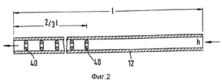
Фигура 2 - в продольном сечении нагревательная труба для барабана швелевания с множеством используемых кольцеобразных завихрителей;
Фигура 3 - увеличенный вырез такой нагревательной трубы;
Фигура 4 - нагревательная труба из фигуры 3 в поперечном сечении;
Фигура 5 - в продольном сечении увеличенный вырез нагревательной трубы с измененным расположением используемых кольцеобразных завихрителей;
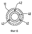
Фигура 6 - нагревательная труба из фигуры 5 в поперечном сечении;
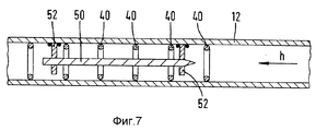
Фигура 7 - в продольном сечении нагревательная труба с используемыми завихрителями и с используемым вытеснительным телом согласно первой форме выполнения и
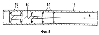
Фигура 8 - в продольном сечении нагревательная труба с используемыми завихрителями и вытеснительным телом согласно второй форме выполнения.Examples of the invention are explained in more detail below with the help of eight figures, which show:
Figure 1 - the inlet of the channeling-burning installation with a channeling drum, the heating pipes of which flow flue gas according to the principle of counterflow;
Figure 2 is a longitudinal section of a heating pipe for a channeling drum with many used annular swirlers;
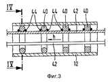
Figure 3 is an enlarged cutout of such a heating pipe;
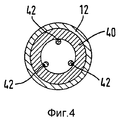
Figure 4 - heating pipe of figure 3 in cross section;
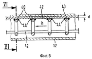
Figure 5 - in longitudinal section, an enlarged cutout of the heating pipe with a modified arrangement of the used annular swirlers;
Figure 6 - heating pipe of figure 5 in cross section;
Figure 7 is a longitudinal section of a heating pipe with swirls used and with a displacing body according to the first embodiment and
Figure 8 is a longitudinal section of a heating pipe with used swirlers and a displacing body according to a second embodiment.
Согласно фигуре 1 твердые отходы А через подводящее или загрузочное устройство 2 с вертикальной шахтой 3 и через шнек 4, который приводится двигателем 6 и расположен в загрузочной трубе 7, вводятся по центру в пиролизный реактор или камеру швелевания 8. Камера швелевания 8 представляет собой в примере выполнения обогреваемый изнутри, вращающийся вокруг своей продольной оси 10 барабан швелевания или пиролиза, который может иметь длину 15-30 метров и работает при температуре 300 - 600 oC, который эксплуатируется в значительной степени без доступа кислорода и наряду с летучим газом швелевания s создает также в значительной степени твердое остаточное вещество пиролиза f. При этом речь идет о барабане швелевания 8 с внутренними трубами с множеством (например, 50 до 200) направленных параллельно друг другу нагревательных труб 12, из которых на фигуре 1 показаны только четыре, которые расположены во внутреннем пространстве 13. На правом или "горячем" конце предусмотрен впуск для топочного газа h в форме неподвижной уплотненной впускной камеры топочного газа 14, а на левом или "холодном" конце расположен выпуск для топочного газа h в форме неподвижной уплотненной выпускной камеры топочного газа 16. Продольная ось 10 барабана швелевания 8 предпочтительно наклонена относительно горизонтали, так что выпуск на лежащем справа "горячем" конце расположен ниже, чем показанный слева впуск для отходов А. Барабан швелевания 8 предпочтительно поддерживается при легком пониженном давлении относительно окружающей среды.According to figure 1, solid waste A through a feed or loading device 2 with a vertical shaft 3 and through a screw 4, which is driven by a motor 6 and is located in the loading pipe 7, are introduced in the center into the pyrolysis reactor or channel 8. The channel 8 is in the example run inside heated, rotating around its longitudinal axis 10, a channel of stirring or pyrolysis, which can have a length of 15-30 meters and operates at a temperature of 300 - 600 o C, which is operated largely without acid hydrogen and along with the volatile channeling gas s also creates a substantially solid pyrolysis residual f. In this case, we are talking about a channeling drum 8 with inner pipes with many (for example, 50 to 200)
К пиролизному барабану 8 на стороне выхода или разгрузки через вращающуюся вместе центральную разгрузочную трубу 17 подключено разгрузочное устройство 18, которое снабжено выпускным патрубком газа швелевания 20 для отвода газа швелевания s и выходом остаточного вещества пиролиза 22 для выдачи твердого остаточного вещества пиролиза f. Подключенный к выпускному патрубку газа швелевания 20 трубопровод газа швелевания соединен с горелкой (не показанной на чертеже) высокотемпературной камеры сжигания. A discharge device 18 is connected to the pyrolysis drum 8 on the outlet or discharge side through a central unloading pipe 17 rotating together, which is equipped with a channeling gas of channel 20 for the removal of channeling gas s and the output of the residual pyrolysis substance 22 to produce solid residual pyrolysis substance f. Connected to the outlet of the channeling gas 20, the channeling channel of the channeling gas is connected to the burner (not shown in the drawing) of the high-temperature combustion chamber.
Вращательное движение барабана швелевания 8 вокруг продольной оси 10 вызывается приводом 24 в форме передачи, которая подключена к двигателю 26. Приводные средства 24, 26 работают, например, на зубчатом венце, который закреплен на окружности барабана швелевания 8. Опоры барабана швелевания 8 обозначены позицией 27. The rotational movement of the channeling drum 8 around the longitudinal axis 10 is caused by the drive 24 in the form of a gear that is connected to the engine 26. The drive means 24, 26 work, for example, on a gear ring, which is mounted on the circumference of the channeling channel 8. The supports of the channeling channel 8 are indicated by 27 .
Из фигуры 1 видно, что нагревательные трубы 12 своим одним концом закреплены на первой концевой плите 28 и своим другим концом на второй концевой плите 30. Крепление на концевых плитах 28, 30 выполнено так, что получается возможность легкой замены нагревательных труб 12. Концы нагревательных труб 12 входят соответственно через отверстие из внутреннего пространства 13 налево в выпускную камеру 16 или соответственно направо во впускную камеру 14. Ось нагревательных труб 12 при этом направлена соответственно перпендикулярно к поверхности концевых плит 28, 30. При показанной конструкции следует учитывать, что отдельные нагревательные трубы 12 подвержены высокой термической и механической нагрузке и что концевые плиты 28, 30, которые могут быть обозначены также как трубные плиты или основания трубы барабана, вращаются вместе вокруг продольной оси 10 барабана швелевания 8. From figure 1 it is seen that the
Между концевыми плитами 28, 30 предусмотрены точки опоры X, Y для опирания (в противном случае возможно провисающих) нагревательных труб 12. При рассмотрении в направлении транспортировки отходов А первая точка опоры X лежит примерно при одной трети (1/3 1), а вторая точка опоры Y лежит примерно при двух третях (2/3 1) общей длины 1 барабана швелевания 8. Здесь предусмотрены несущие или опорные кронштейны 31, 32 в форме скругленных перфорированных плит из металла, например из стали. Они закреплены на внутренней стенке 33. Between the end plates 28, 30, support points X, Y are provided for supporting (otherwise possibly sagging) the
Согласно фигуре 2 нагревательная труба 12 протекается в направлении стрелки топочным газом h. В левой частичной области нагревательной трубы 12, а именно там, где должна иметь место хорошая теплопередача на поступающие в барабан швелевания отходы А с целью испарения содержащейся там влаги, то есть в конечной области или специально в последних двух третях длины 1, (при рассмотрении в направлении течения топочного газа h) внутри расположено множество завихрителей 40. При этом речь идет специально о кольцеобразных завихрителях или завихрительных кольцах, которые расположены на равномерном или не равномерном расстоянии друг от друга вдоль направления течения. Они выполнены предпочтительно из нержавеющей стали. Они служат для того, чтобы создавать в 2/3 1-области нагревательной трубы 12 высокое завихрение в граничном слое и таким образом повышение скорости газа. Это приводит к лучшей теплопередаче топочного газа h, который охлаждается на своем пути справа налево. According to figure 2, the
Из фигур 3 и 4 ясно, что завихрительные кольца 40 могут иметь круглое или прямоугольное, специально также квадратное поперечное сечение. From figures 3 and 4 it is clear that the swirl rings 40 can have a round or rectangular, especially also square cross-section.
Завихрительные кольца 40 размещены здесь внутри нагревательной трубы 12 с помощью трех простирающихся в продольном направлении дистанционно удерживающих проводов 42. Места сварки между завихрительными кольцами 40 и дистанционно удерживающими проводами 42 обозначены позицией 44. На фигурах 3 и 4 завихрительные кольца 40 прилегают к внутренней стенке нагревательной трубы 12. Они уменьшают в своей области действия свободное поперечное сечение для топочного газа h, повышают тем самым скорость течения и приводят к образованию завихрений. Тем самым, как уже пояснялось, повышается теплопередача от топочного газа h на нагревательную трубу 12 и оттуда на отходы. Vortex rings 40 are placed here inside the
Дальнейшая форма выполнения показана на фигурах 5 и 6. Здесь завихрительные кольца 40 удерживаются на определенном расстоянии d относительно внутренней стенки нагревательной трубы 12. Предпочтительным является концентричное расположение. Чтобы поддерживать это расстояние d и взаимное расстояние завихрительных колец 40 опять-таки предусмотрены удерживающие провода 42. Они здесь расположены на внешней стороне отдельных завихрительных колец 40 и закреплены там с помощью сварных швов 44. Толщина d удерживающих проводов 42 соответствует расстоянию d между внешним диаметром завихрительных колец 40 и внутренним диаметром нагревательной трубы 12. Эффект относительно теплопередачи является практически таким же, что и в форме выполнения согласно фигурам 3 и 4. A further embodiment is shown in figures 5 and 6. Here, the swirl rings 40 are held at a certain distance d relative to the inner wall of the
На фигурах 7 и 8 показаны формы дальнейшего развития. Уже было упомянуто, что с охлаждением топочного газа h скорость его течения уменьшается. Эта скорость течения снова повышается с помощью, по меньшей мере, одного вытеснительного тела 50, которое расположено, в частности, концентрично в нагревательной трубе 12. В комбинации с описанными завихрителями 40 таким образом снова получается повышение теплопередачи. Таким образом по всей длине 1 отдельных нагревательных труб 12, несмотря на охлаждение топочного газа h, достигается примерно равномерная теплопередача от топочного газа h на стенку соответствующей нагревательной трубы 12. Эти меры могут приводить к тому, что по сравнению с обычным выполнением длина барабана швелевания 8 может быть более короткой. Это приводит к достойному упоминания уменьшению расходов на изготовление барабана швелевания 8. In figures 7 and 8 shows forms of further development. It has already been mentioned that with cooling of the flue gas h, its flow rate decreases. This flow rate is again increased by means of at least one displacing
На фигуре 7 показано, что вытесняющее тело 50, которое предпочтительно выполнено из нержавеющей стали, может быть выполнено в основном цилиндрическим. Вершина вытесняющего тела 50 направлена навстречу топочному газу h. На фигуре 8 в противоположность этому показано, что вытесняющее тело 50, которое также может быть выполнено из нержавеющей стали, может быть выполнено в виде пирамиды или конуса. Также и здесь вершина вытесняющего тела 50 направлена против течения. Figure 7 shows that the displacing
Вытесняющие тела 50 из фигур 7 и 8 закреплены соответственно концентрично в нагревательной трубе 12. Для этого служат соответственно три аксиально смещенные относительно друг друга на 120o опорные ножки 52, которые предусмотрены на переднем и заднем конце вытесняющего тела 50. Такие опорные ножки 52 показаны для наглядности только на фигуре 7. Длина вытесняющего тела 50 простирается соответственно на несколько завихрительных колец 40. Вдоль всего участка 2/3 1 может быть предусмотрено множество вытесняющих тел 50.The displacing
Claims (12)
Applications Claiming Priority (2)
| Application Number | Priority Date | Filing Date | Title |
|---|---|---|---|
| DEP4429908.7 | 1994-08-23 | ||
| DE4429908A DE4429908A1 (en) | 1994-08-23 | 1994-08-23 | Heating chamber for solid goods equipped with heating pipes |
Publications (2)
| Publication Number | Publication Date |
|---|---|
| RU95113728A RU95113728A (en) | 1997-07-10 |
| RU2138535C1 true RU2138535C1 (en) | 1999-09-27 |
Family
ID=6526375
Family Applications (1)
| Application Number | Title | Priority Date | Filing Date |
|---|---|---|---|
| RU95113728/02A RU2138535C1 (en) | 1994-08-23 | 1995-08-18 | Furnace for hard material |
Country Status (17)
| Country | Link |
|---|---|
| US (1) | US5769007A (en) |
| EP (1) | EP0703288B1 (en) |
| JP (1) | JP3607757B2 (en) |
| KR (1) | KR100359416B1 (en) |
| CN (1) | CN1071369C (en) |
| AT (1) | ATE173004T1 (en) |
| CA (1) | CA2156589A1 (en) |
| CZ (1) | CZ287011B6 (en) |
| DE (2) | DE4429908A1 (en) |
| DK (1) | DK0703288T3 (en) |
| ES (1) | ES2124478T3 (en) |
| HU (1) | HU215011B (en) |
| MY (1) | MY132080A (en) |
| PL (1) | PL178974B1 (en) |
| RU (1) | RU2138535C1 (en) |
| SK (1) | SK281364B6 (en) |
| TW (1) | TW269724B (en) |
Families Citing this family (25)
| Publication number | Priority date | Publication date | Assignee | Title |
|---|---|---|---|---|
| US6189463B1 (en) * | 1998-05-12 | 2001-02-20 | General Technology, Inc. | Methods and apparatus for incinerating combustible waste material such as farm animal biomass |
| JP3266591B2 (en) * | 1999-12-10 | 2002-03-18 | アートセラミック株式会社 | Intermittent flow type pyrolysis equipment |
| JP2007064514A (en) * | 2005-08-29 | 2007-03-15 | Usui Kokusai Sangyo Kaisha Ltd | Heat transfer tube for heat exchanger, and heat exchanger incorporating the heat transfer tube |
| DE102005051417A1 (en) * | 2005-10-27 | 2007-05-03 | X-Fab Semiconductor Foundries Ag | Simulation or layout method for vertical power transistors with variable channel width and variable gate-drain capacitance |
| DE102007005799B4 (en) * | 2006-10-18 | 2018-01-25 | Heinz-Jürgen Mühlen | Process for producing a hydrogen-rich product gas |
| JP4752816B2 (en) * | 2007-06-27 | 2011-08-17 | セントラル硝子株式会社 | Functional gas production equipment |
| RU2364451C1 (en) * | 2008-07-21 | 2009-08-20 | Сергей Юрьевич Вильчек | Universal method for processing of materials in sectional apparatus of drum type with through holes in partitions between sections and device for its realisation |
| JP5695348B2 (en) * | 2009-09-14 | 2015-04-01 | 高砂工業株式会社 | Rotary kiln |
| DE102011078944B4 (en) * | 2011-07-11 | 2014-09-25 | Coperion Gmbh | Bulk material heat exchanger device, heat exchanger system for bulk material with at least one such bulk material heat exchanger device and method for operating such a heat exchanger system |
| US9920635B2 (en) * | 2014-09-09 | 2018-03-20 | Honeywell International Inc. | Turbine blades and methods of forming turbine blades having lifted rib turbulator structures |
| GB2536048A (en) * | 2015-03-05 | 2016-09-07 | Standard Gas Ltd | Advanced thermal treatment methods and apparatus |
| JP2018080843A (en) * | 2015-03-20 | 2018-05-24 | パナソニックIpマネジメント株式会社 | Heat exchanger |
| CN105650648B (en) * | 2016-03-26 | 2018-06-12 | 福建泉成机械有限公司 | Waste turbulent burner and its waste turbulent combustion method |
| CN106111020B (en) * | 2016-08-31 | 2019-09-06 | 广东新生环保科技股份有限公司 | A kind of macromolecule pyrolysis furnace |
| CN107192278A (en) * | 2017-03-27 | 2017-09-22 | 黄云生 | High temperature resistant shoe last tube core heat exchanger |
| NL2019553B1 (en) | 2017-09-14 | 2019-03-27 | Torrgas Tech B V | Process to prepare an activated carbon product and a syngas mixture |
| NL2019552B1 (en) | 2017-09-14 | 2019-03-27 | Torrgas Tech B V | Process to prepare a char product and a syngas mixture |
| CN107687773A (en) * | 2017-09-15 | 2018-02-13 | 新疆广汇煤炭清洁炼化有限责任公司 | Cooling drying system |
| CN109608013B (en) * | 2018-11-14 | 2021-11-30 | 杭州职业技术学院 | Cow dung biogas residue drying equipment |
| US20240101907A1 (en) | 2019-10-29 | 2024-03-28 | Michiel Cramwinckel | Process for a plastic product conversion |
| KR102507913B1 (en) | 2021-02-02 | 2023-03-07 | 연세대학교 원주산학협력단 | Turbulator apparatus and assembling method thereof |
| KR102507914B1 (en) * | 2021-02-08 | 2023-03-07 | 연세대학교 원주산학협력단 | Turbulator apparatus and assembling method thereof |
| KR102436569B1 (en) | 2021-02-25 | 2022-08-24 | 연세대학교 원주산학협력단 | Turbulator apparatus |
| EP4330344A2 (en) | 2021-04-28 | 2024-03-06 | Torrgas Technology B.V. | Process to prepare lower olefins |
| WO2023135114A1 (en) | 2022-01-11 | 2023-07-20 | Torrgas Technology B.V | Process to prepare synthesis gas |
Family Cites Families (17)
| Publication number | Priority date | Publication date | Assignee | Title |
|---|---|---|---|---|
| DE382865C (en) * | 1923-10-08 | Albert Dargatz Fa | Swirler for heat exchange devices | |
| DE505561C (en) * | 1922-05-21 | 1930-09-18 | Kohlenveredlung Akt Ges | Oven for drying and smoldering |
| DE1931148A1 (en) * | 1969-06-19 | 1971-01-07 | Otte & Co Kg Laurenz | Conical flue gas duct |
| DE2539933C3 (en) * | 1975-09-09 | 1979-06-21 | Heinrich Tritschler Gmbh & Co Kg Maschinen- U. Ofenfabrik, 8750 Aschaffenburg | Use in a flue pipe of a boiler to increase the turbulence of the flue gas |
| US4028817A (en) * | 1975-09-29 | 1977-06-14 | Auto-Heat, Inc. | Apparatus for recovery of heat from exhaust gases of dryer |
| DE2944693A1 (en) * | 1979-11-06 | 1981-05-14 | Hölter, Ing.(grad.), Heinz, 4390 Gladbeck | Rotary drum furnace for pyrolysis of garbage - has axial radiant heating tube contg. burner, and separate outlets for pyrolysis gases and coke |
| GB2097910B (en) * | 1981-03-20 | 1984-10-31 | Gavin Cal Ltd | Insert for placement in a vessel |
| DE3346338A1 (en) * | 1983-12-22 | 1985-07-11 | Pka Pyrolyse Kraftanlagen Gmbh, 7080 Aalen | ROTATING SUSPENSION DRUM FOR SUSPENSIONING WASTE |
| US4693302A (en) * | 1984-12-28 | 1987-09-15 | Leonard Oboler | Heat exchanging apparatus for cooling and condensing by evaporation |
| DE3706771A1 (en) * | 1987-03-03 | 1988-09-22 | Gutehoffnungshuette Man | Rotary drum for carbonising wastes with exclusion of air |
| DE3702318C1 (en) * | 1987-01-27 | 1988-01-28 | Gutehoffnungshuette Man | Rotary drum for the carbonisation of wastes with exclusion of air |
| DE3811820A1 (en) | 1987-08-03 | 1989-02-16 | Siemens Ag | METHOD AND SYSTEM FOR THERMAL WASTE DISPOSAL |
| DE3830153A1 (en) | 1988-09-05 | 1990-03-15 | Siemens Ag | Pyrolysis reactor with indirect and direct heating |
| US4889060A (en) * | 1989-01-27 | 1989-12-26 | Westinghouse Electric Corp. | Web for rotary combustor |
| US5103745A (en) * | 1991-02-25 | 1992-04-14 | Westinghouse Electric Corp. | Movable air seals for a rotary combustor |
| DE4329871A1 (en) * | 1993-09-03 | 1995-03-09 | Siemens Ag | Pipe-rotatable heating chamber for waste |
| DE9319041U1 (en) * | 1993-12-11 | 1994-02-24 | Babcock Bsh Ag | Rotary drum |
-
1994
- 1994-08-23 DE DE4429908A patent/DE4429908A1/en not_active Withdrawn
-
1995
- 1995-08-03 TW TW084108090A patent/TW269724B/zh active
- 1995-08-08 CN CN95115378A patent/CN1071369C/en not_active Expired - Fee Related
- 1995-08-10 DK DK95112613T patent/DK0703288T3/en active
- 1995-08-10 AT AT95112613T patent/ATE173004T1/en not_active IP Right Cessation
- 1995-08-10 EP EP95112613A patent/EP0703288B1/en not_active Expired - Lifetime
- 1995-08-10 DE DE59504128T patent/DE59504128D1/en not_active Expired - Fee Related
- 1995-08-10 ES ES95112613T patent/ES2124478T3/en not_active Expired - Lifetime
- 1995-08-16 CZ CZ19952095A patent/CZ287011B6/en not_active IP Right Cessation
- 1995-08-18 JP JP23337395A patent/JP3607757B2/en not_active Expired - Fee Related
- 1995-08-18 RU RU95113728/02A patent/RU2138535C1/en not_active IP Right Cessation
- 1995-08-21 CA CA002156589A patent/CA2156589A1/en not_active Abandoned
- 1995-08-21 PL PL95310104A patent/PL178974B1/en unknown
- 1995-08-21 MY MYPI95002462A patent/MY132080A/en unknown
- 1995-08-22 US US08/518,009 patent/US5769007A/en not_active Expired - Fee Related
- 1995-08-22 HU HU9502453A patent/HU215011B/en not_active IP Right Cessation
- 1995-08-23 SK SK1035-95A patent/SK281364B6/en unknown
- 1995-08-23 KR KR1019950026077A patent/KR100359416B1/en not_active IP Right Cessation
Also Published As
| Publication number | Publication date |
|---|---|
| CN1126236A (en) | 1996-07-10 |
| JPH0875132A (en) | 1996-03-19 |
| CA2156589A1 (en) | 1996-02-24 |
| DE4429908A1 (en) | 1996-02-29 |
| CZ287011B6 (en) | 2000-08-16 |
| CN1071369C (en) | 2001-09-19 |
| MY132080A (en) | 2007-09-28 |
| PL310104A1 (en) | 1996-03-04 |
| ES2124478T3 (en) | 1999-02-01 |
| DK0703288T3 (en) | 1999-07-19 |
| TW269724B (en) | 1996-02-01 |
| SK103595A3 (en) | 1998-08-05 |
| CZ209595A3 (en) | 1996-05-15 |
| DE59504128D1 (en) | 1998-12-10 |
| EP0703288A1 (en) | 1996-03-27 |
| KR960008255A (en) | 1996-03-22 |
| JP3607757B2 (en) | 2005-01-05 |
| EP0703288B1 (en) | 1998-11-04 |
| HU9502453D0 (en) | 1995-10-30 |
| US5769007A (en) | 1998-06-23 |
| ATE173004T1 (en) | 1998-11-15 |
| SK281364B6 (en) | 2001-02-12 |
| PL178974B1 (en) | 2000-07-31 |
| HUT76154A (en) | 1997-07-28 |
| KR100359416B1 (en) | 2003-01-15 |
| HU215011B (en) | 1998-08-28 |
Similar Documents
| Publication | Publication Date | Title |
|---|---|---|
| RU2138535C1 (en) | Furnace for hard material | |
| RU2103316C1 (en) | Waste-combustion rotary furnace chamber with internal tubes | |
| EA001294B1 (en) | Gasification reactor apparatus | |
| JPH01500251A (en) | How to reduce NOx in flue gas | |
| US4120644A (en) | Apparatus for regeneration of spent active carbon | |
| FI89734C (en) | FOERFARANDE OCH ANORDNING FOER BEHANDLING AV GASER FRAON FOERGASNINGS- ELLER FOERBRAENNINGSANLAEGGNINGAR | |
| KR20130126508A (en) | Integrated gas cooling system for electric arc furnace | |
| JPH0868596A (en) | Rotary type heat transfer and heating type purifier applied to exhaust gas | |
| KR20120067047A (en) | Heat recovery system with improved heat recovery rate and combined heat and power generation system using this | |
| RU2385438C1 (en) | System for utilisation of moist carbon containing wastes | |
| CN202253558U (en) | Heat recovery system and cogeneration system utilizing same | |
| CN116007356A (en) | Device and method for preventing low-temperature drying hardening of titanium concentrate rotary kiln | |
| HUT60851A (en) | Multilateral water-cooled rotary combustion chamber | |
| JPH10318A (en) | Dust removing device for high-temperature gas | |
| RU2133409C1 (en) | Wood waste incinerator | |
| JP6523007B2 (en) | Fluidized bed incinerator | |
| WO2022089323A1 (en) | Swirler | |
| RU2756150C1 (en) | Integrated heat generating plant | |
| JP2002085932A (en) | Indirect water cooling method of waste combustion gas | |
| JP4390173B2 (en) | Combustion treatment equipment and method | |
| RU1805268C (en) | Dust concentrator | |
| JP3431407B2 (en) | Dry distillation pyrolysis reactor for waste | |
| RU13795U1 (en) | INSTALLATION FOR ACTIVE CARBON | |
| RU2625189C1 (en) | System for recycling wet carbon-containing wastes | |
| CN105713670A (en) | Refuse disposal system |
Legal Events
| Date | Code | Title | Description |
|---|---|---|---|
| MM4A | The patent is invalid due to non-payment of fees |
Effective date: 20030819 |