RU2129478C1 - Bag production method - Google Patents
Bag production method Download PDFInfo
- Publication number
- RU2129478C1 RU2129478C1 RU97119636/12A RU97119636A RU2129478C1 RU 2129478 C1 RU2129478 C1 RU 2129478C1 RU 97119636/12 A RU97119636/12 A RU 97119636/12A RU 97119636 A RU97119636 A RU 97119636A RU 2129478 C1 RU2129478 C1 RU 2129478C1
- Authority
- RU
- Russia
- Prior art keywords
- tube
- folding
- folds
- bag
- weld
- Prior art date
Links
Images


Classifications
-
- G—PHYSICS
- G09—EDUCATION; CRYPTOGRAPHY; DISPLAY; ADVERTISING; SEALS
- G09F—DISPLAYING; ADVERTISING; SIGNS; LABELS OR NAME-PLATES; SEALS
- G09F3/00—Labels, tag tickets, or similar identification or indication means; Seals; Postage or like stamps
- G09F3/08—Fastening or securing by means not forming part of the material of the label itself
- G09F3/10—Fastening or securing by means not forming part of the material of the label itself by an adhesive layer
-
- B—PERFORMING OPERATIONS; TRANSPORTING
- B29—WORKING OF PLASTICS; WORKING OF SUBSTANCES IN A PLASTIC STATE IN GENERAL
- B29C—SHAPING OR JOINING OF PLASTICS; SHAPING OF MATERIAL IN A PLASTIC STATE, NOT OTHERWISE PROVIDED FOR; AFTER-TREATMENT OF THE SHAPED PRODUCTS, e.g. REPAIRING
- B29C63/00—Lining or sheathing, i.e. applying preformed layers or sheathings of plastics; Apparatus therefor
- B29C63/0004—Component parts, details or accessories; Auxiliary operations
- B29C63/0013—Removing old coatings
-
- B—PERFORMING OPERATIONS; TRANSPORTING
- B31—MAKING ARTICLES OF PAPER, CARDBOARD OR MATERIAL WORKED IN A MANNER ANALOGOUS TO PAPER; WORKING PAPER, CARDBOARD OR MATERIAL WORKED IN A MANNER ANALOGOUS TO PAPER
- B31B—MAKING CONTAINERS OF PAPER, CARDBOARD OR MATERIAL WORKED IN A MANNER ANALOGOUS TO PAPER
- B31B70/00—Making flexible containers, e.g. envelopes or bags
-
- B—PERFORMING OPERATIONS; TRANSPORTING
- B32—LAYERED PRODUCTS
- B32B—LAYERED PRODUCTS, i.e. PRODUCTS BUILT-UP OF STRATA OF FLAT OR NON-FLAT, e.g. CELLULAR OR HONEYCOMB, FORM
- B32B3/00—Layered products comprising a layer with external or internal discontinuities or unevennesses, or a layer of non-planar form; Layered products having particular features of form
- B32B3/10—Layered products comprising a layer with external or internal discontinuities or unevennesses, or a layer of non-planar form; Layered products having particular features of form characterised by a discontinuous layer, i.e. formed of separate pieces of material
-
- B—PERFORMING OPERATIONS; TRANSPORTING
- B65—CONVEYING; PACKING; STORING; HANDLING THIN OR FILAMENTARY MATERIAL
- B65C—LABELLING OR TAGGING MACHINES, APPARATUS, OR PROCESSES
- B65C3/00—Labelling other than flat surfaces
- B65C3/06—Affixing labels to short rigid containers
- B65C3/08—Affixing labels to short rigid containers to container bodies
-
- B—PERFORMING OPERATIONS; TRANSPORTING
- B65—CONVEYING; PACKING; STORING; HANDLING THIN OR FILAMENTARY MATERIAL
- B65C—LABELLING OR TAGGING MACHINES, APPARATUS, OR PROCESSES
- B65C9/00—Details of labelling machines or apparatus
- B65C9/0015—Preparing the labels or articles, e.g. smoothing, removing air bubbles
-
- B—PERFORMING OPERATIONS; TRANSPORTING
- B65—CONVEYING; PACKING; STORING; HANDLING THIN OR FILAMENTARY MATERIAL
- B65C—LABELLING OR TAGGING MACHINES, APPARATUS, OR PROCESSES
- B65C9/00—Details of labelling machines or apparatus
- B65C9/20—Gluing the labels or articles
- B65C9/22—Gluing the labels or articles by wetting, e.g. by applying liquid glue or a liquid to a dry glue coating
- B65C9/2204—Gluing the labels or articles by wetting, e.g. by applying liquid glue or a liquid to a dry glue coating using spraying means
- B65C9/2213—Applying the liquid on the label
- B65C9/2217—Applying the liquid on the label discretely, i.e. several points or strips or interrupted films
-
- B—PERFORMING OPERATIONS; TRANSPORTING
- B31—MAKING ARTICLES OF PAPER, CARDBOARD OR MATERIAL WORKED IN A MANNER ANALOGOUS TO PAPER; WORKING PAPER, CARDBOARD OR MATERIAL WORKED IN A MANNER ANALOGOUS TO PAPER
- B31B—MAKING CONTAINERS OF PAPER, CARDBOARD OR MATERIAL WORKED IN A MANNER ANALOGOUS TO PAPER
- B31B2155/00—Flexible containers made from webs
-
- B—PERFORMING OPERATIONS; TRANSPORTING
- B31—MAKING ARTICLES OF PAPER, CARDBOARD OR MATERIAL WORKED IN A MANNER ANALOGOUS TO PAPER; WORKING PAPER, CARDBOARD OR MATERIAL WORKED IN A MANNER ANALOGOUS TO PAPER
- B31B—MAKING CONTAINERS OF PAPER, CARDBOARD OR MATERIAL WORKED IN A MANNER ANALOGOUS TO PAPER
- B31B2160/00—Shape of flexible containers
- B31B2160/10—Shape of flexible containers rectangular and flat, i.e. without structural provision for thickness of contents
-
- B—PERFORMING OPERATIONS; TRANSPORTING
- B31—MAKING ARTICLES OF PAPER, CARDBOARD OR MATERIAL WORKED IN A MANNER ANALOGOUS TO PAPER; WORKING PAPER, CARDBOARD OR MATERIAL WORKED IN A MANNER ANALOGOUS TO PAPER
- B31B—MAKING CONTAINERS OF PAPER, CARDBOARD OR MATERIAL WORKED IN A MANNER ANALOGOUS TO PAPER
- B31B50/00—Making rigid or semi-rigid containers, e.g. boxes or cartons
- B31B50/26—Folding sheets, blanks or webs
- B31B50/36—Folding sheets, blanks or webs by continuously feeding the sheets, blanks or webs to stationary members, e.g. plates, ploughs or cores
-
- B—PERFORMING OPERATIONS; TRANSPORTING
- B31—MAKING ARTICLES OF PAPER, CARDBOARD OR MATERIAL WORKED IN A MANNER ANALOGOUS TO PAPER; WORKING PAPER, CARDBOARD OR MATERIAL WORKED IN A MANNER ANALOGOUS TO PAPER
- B31B—MAKING CONTAINERS OF PAPER, CARDBOARD OR MATERIAL WORKED IN A MANNER ANALOGOUS TO PAPER
- B31B70/00—Making flexible containers, e.g. envelopes or bags
- B31B70/26—Folding sheets, blanks or webs
- B31B70/262—Folding sheets, blanks or webs involving longitudinally folding, i.e. along a line parallel to the direction of movement
- B31B70/266—Folding sheets, blanks or webs involving longitudinally folding, i.e. along a line parallel to the direction of movement involving gusset-forming
-
- B—PERFORMING OPERATIONS; TRANSPORTING
- B31—MAKING ARTICLES OF PAPER, CARDBOARD OR MATERIAL WORKED IN A MANNER ANALOGOUS TO PAPER; WORKING PAPER, CARDBOARD OR MATERIAL WORKED IN A MANNER ANALOGOUS TO PAPER
- B31B—MAKING CONTAINERS OF PAPER, CARDBOARD OR MATERIAL WORKED IN A MANNER ANALOGOUS TO PAPER
- B31B70/00—Making flexible containers, e.g. envelopes or bags
- B31B70/26—Folding sheets, blanks or webs
- B31B70/36—Folding sheets, blanks or webs by continuously feeding them to stationary members, e.g. plates, ploughs or cores
-
- B—PERFORMING OPERATIONS; TRANSPORTING
- B31—MAKING ARTICLES OF PAPER, CARDBOARD OR MATERIAL WORKED IN A MANNER ANALOGOUS TO PAPER; WORKING PAPER, CARDBOARD OR MATERIAL WORKED IN A MANNER ANALOGOUS TO PAPER
- B31B—MAKING CONTAINERS OF PAPER, CARDBOARD OR MATERIAL WORKED IN A MANNER ANALOGOUS TO PAPER
- B31B70/00—Making flexible containers, e.g. envelopes or bags
- B31B70/74—Auxiliary operations
- B31B70/86—Forming integral handles or mounting separate handles
- B31B70/872—Forming integral handles on bags
-
- B—PERFORMING OPERATIONS; TRANSPORTING
- B65—CONVEYING; PACKING; STORING; HANDLING THIN OR FILAMENTARY MATERIAL
- B65C—LABELLING OR TAGGING MACHINES, APPARATUS, OR PROCESSES
- B65C9/00—Details of labelling machines or apparatus
- B65C9/0015—Preparing the labels or articles, e.g. smoothing, removing air bubbles
- B65C2009/0018—Preparing the labels
- B65C2009/0021—Preparing the labels for temporary attachment to transfer means or to the article
Abstract
Description
Настоящее изобретение относится к способу и устройству для изготовления пластиковых сумок, например, пакетов для сбора мусора. The present invention relates to a method and apparatus for manufacturing plastic bags, for example, garbage collection bags.
Хорошо известен способ изготовления пластиковых сумок из бесконечной трубки, полученной экструдированием из полиэтилена. Полученную экструдированием трубку вытягивают, для того, чтобы уменьшить толщину полиэтиленовой пленки, складывают, формируют сварной шов и отрезают в поперечном направлении трубки так, чтобы сварные швы образовывали нижние части сумок. Ручки могут быть образованы путем удаления верхней средней части сумок, и благодаря созданию ряда поперечных линий перфорации, а не разрезанием трубки, можно изготавливать ряд сумок, которые могут быть скатаны в рулон. Для уменьшения ширины рулона сумок и для уменьшения размеров оборудования для изготовления сумок, известен способ складывания боковых сторон трубки внутрь для образования внутренних складок до выполнения сварного шва. A well-known method of manufacturing plastic bags from an endless tube obtained by extrusion from polyethylene. The tube obtained by extrusion is pulled in order to reduce the thickness of the plastic film, fold, form a weld and cut in the transverse direction of the tube so that the welds form the lower parts of the bags. Handles can be formed by removing the upper middle part of the bags, and by creating a series of transverse perforation lines rather than cutting the tube, a number of bags can be made that can be rolled up. To reduce the width of the roll of bags and to reduce the size of the equipment for the manufacture of bags, there is a method of folding the sides of the tube inward to form internal folds before making a weld.
Известен также способ складывания трубки с образованием внутренних складок до выполнения сварного шва, описанный в патенте Великобритании GB-A-1 584 746, кл. B 65 D 30/10, публ. 18.02.81, который позволяет выполнять особо прочный шов. Однако, этот способ укладки не подходит для изготовления рулонов из соединенных между собой сумок, сформированных вместе с ручками, так как в ходе операции складывания ручки укладывают в ту же сторону, куда складывают саму трубку, и в результате ряд сумок не может быть должным образом накатан в рулон. Ручки на открытом крае сумки часто желательны для завязывания сумки в плотный пакет после его заполнения, например, отбросами, или для удобства ношения сумки. There is also a method of folding the tube with the formation of internal folds before performing a weld, described in British patent GB-A-1 584 746, class. B 65
В патенте Великобритании GB-A-2 274 446, кл. D 65 D 30/10, публ. 27.07.94 недостатки описанного выше способа складывания преодолены путем создания сумки, у которой противоположные боковые внутренние складки, сложенные относительно продольных линий сгиба, отогнуты на противоположные стороны относительно средней части сумки. British Patent GB-A-2 274,446, cl. D 65
Способ складывания сумки, описанный в патенте GB-A-2 274 446, сохраняет преимущества, заключающиеся в образовании прочного нижнего шва. Он также позволяет изготавливать сумку с ручками, которая, в сложенном виде, существенно уже, чем известные до тех пор сумки с ручками, и ручки сложенной сумки могут быть распложены по разные стороны сумки, что желательно, когда ряд сумок необходимо скатать в рулон. The bag folding method described in GB-A-2 274 446 retains the advantages of forming a durable lower seam. It also allows the manufacture of a bag with handles, which, when folded, is substantially narrower than previously known bags with handles, and the handles of a folded bag can be placed on opposite sides of the bag, which is desirable when a number of bags need to be rolled up.
Кроме того, известный способ складывания сумки не обеспечивает необходимого качества складывания. In addition, the known method of folding the bag does not provide the required quality of folding.
Задачей изобретения является повышение качества складывания и дальнейшее усовершенствование существующих способов. The objective of the invention is to improve the quality of folding and further improve existing methods.
Таким образом настоящее изобретение относится к усовершенствованному способу изготовления сумки из сплющенной трубки, включающему первое складывание продольных краев трубки с образованием внутренних складок, последующее складывание сплющенной трубки с внутренними складками с целью уменьшения ширины трубки, при котором части, образующие внутренние складки, отгибают последовательно относительно соответствующих продольных линий перегиба таким образом, чтобы расположить их с противоположных сторон от средней части трубки, расположенной между частями, образующими внутренние складки, образование поперечного сварного шва на сложенной трубке с внутренними складками для создания дна сумки и формирование ручек между операциями складывания, причем согласно изобретению формирование ручек осуществляют путем удаления средней части сложенной трубки с внутренними складками и путем образования поперечного сварного шва на трубке в месте, соответствующем концам ручек, при этом части, образующие внутренние складки, отгибают последовательно относительно соответствующих продольных линий перегиба. Thus, the present invention relates to an improved method for manufacturing a bag from a flattened tube, including first folding the longitudinal edges of the tube with the formation of internal folds, then folding the flattened tube with internal folds in order to reduce the width of the tube, in which the parts forming the internal folds are folded sequentially relative to the corresponding longitudinal inflection lines in such a way as to position them on opposite sides from the middle part of the tube between the parts forming the inner folds, the formation of a transverse weld on a folded tube with inner folds to create the bottom of the bag and the formation of handles between folding operations, and according to the invention, the formation of handles is carried out by removing the middle part of the folded tube with inner folds and by forming a transverse weld on the tube in a place corresponding to the ends of the handles, while the parts forming the inner folds are bent sequentially relative to the corresponding products ol inflection lines.
Предпочтительно трубку складывают так, чтобы образовать сложенные треугольником складки, причем складки обращены внутрь на глубину, составляющую преимущественно одну треть ширины трубки со сформированными внутренними складками. Preferably, the tube is folded so as to form folded triangles, the folds facing inward to a depth that is predominantly one third of the width of the tube with internal folds formed.
Кроме того, в предпочтительном исполнении настоящего способа внутреннюю складку формируют путем пропускания сплющенной трубки относительно отдельного дугового складывающего клина, имеющего боковую грань, относительно которой трубку перегибают. Перед и после каждого складывающего клина располагают зажимные пары роликов, натяжение трубки во время ее прохождения по складывающему клину контролируют путем регулирования относительно скорости зажимных пар роликов и ориентацию зажимных пар роликов регулируют для поддержания в существенной степени равномерного натяжения в поперечном направлении трубки во время ее прохождения относительно складывающего клина. Регулирование ориентации зажимов позволяет получать удовлетворительное качество складок несмотря на асимметричность двух стадий второго этапа складывания. In addition, in a preferred embodiment of the present method, the inner fold is formed by passing a flattened tube relative to a separate arc folding wedge having a side face relative to which the tube is bent. Clamping pairs of rollers are placed before and after each folding wedge, the tension of the tube during its passage through the folding wedge is controlled by adjusting the speed of the clamping pairs of rollers relative to the speed and the orientation of the clamping pairs of rollers is controlled to maintain a substantially uniform tension in the transverse direction of the tube relative to folding wedge. Adjusting the orientation of the clamps allows you to obtain a satisfactory quality of the folds despite the asymmetry of the two stages of the second folding stage.
Хотя порядок, в котором выполняют этапы удаления средней части трубки с внутренними складками и формирования сварного шва на трубке в месте, соответствующем концам ручек, вполне можно поменять на обратный, было установлено, что процесс изготовления сумки легче контролировать тогда, когда поперечный сварной шов не трубке выполняют в месте, соответствующем концам ручек, до того, как будет удалена средняя часть трубки со сформированными внутренними складками. Although the order in which the steps of removing the middle part of the tube with the inner folds and forming the weld on the tube in the place corresponding to the ends of the handles are performed can be reversed, it was found that the bag manufacturing process is easier to control when the transverse weld is not in the tube performed in a place corresponding to the ends of the handles, before the middle part of the tube with the formed internal folds is removed.
Скорость трубки между первым складыванием и свариванием поперечным швом в сложенном состоянии с внутренними складками контролируют, используя сигнал, генерируемый в соответствии со скоростью, которую имеет трубка после первого складывания. The speed of the tube between the first folding and welding with the transverse seam in the folded state with the inner folds is controlled using a signal generated in accordance with the speed that the tube has after the first folding.
Далее в предпочтительном варианте исполнения настоящего способа ряд сумок формируют из непрерывной склюшенной трубки так, что ручки одной сумки присоединены к основанию следующей сумки, при этом создают поперечную линию ослабления прочности между соседними сварными швами, разделяющими основания и ручки, для обеспечения удобства отделения каждой сумки, причем упомянутую линию ослабления прочности выполняют после того, как складывание двух сумок, соединенных по линии ослабления прочности, будет завершено. Благодаря созданию поперечных линий ослабления прочности, например, рядов перфорации, после того как труба была сложена, трубку можно подвергнуть большему натяжению во время складывания, чем это возможно в любых других случаях, и, следовательно, скорость подачи трубки и скорость изготовления сумок могут быть увеличены. Further, in a preferred embodiment of the present method, a number of bags are formed from a continuous bent tube so that the handles of one bag are attached to the base of the next bag, thereby creating a transverse line of weakening of strength between adjacent welds separating the bases and handles, to ensure the convenience of separating each bag, moreover, the said line of weakening of strength is performed after the folding of two bags connected along the line of weakening of strength is completed. By creating transverse weakening lines, for example, perforation rows, after the pipe has been folded, the pipe can be subjected to more tension during folding than is possible in any other cases, and therefore the tube feed rate and bag manufacturing speed can be increased .
Настоящим изобретением также создано устройство для производства ряда сумок из сплющенной трубки, содержащее средство для выполнения первого этапа складывания для складывания продольных краев трубки и образования внутренних складок, средство для выполнения второго этапа складывания для последующего складывания трубки с внутренними складками с целью уменьшения ширины трубки, выполненное с возможностью последовательного отгибания частей, содержащих внутренние складки, относительно соответствующих продольных линий перегиба последовательно так, чтобы они были размещены по разные стороны от средней части трубки внутренними складками, средство для образования поперечного сварного шва на сложенной с внутренними складками трубке для создания дна сумки, средство для выполнения поперечной линии ослабления прочности, расположенной поперек трубки для облегчения отделения каждой сумки, режущее средство для удаления средней части трубки и образования ручек и средство для создания сварного шва для образования поперечного шва на трубке в месте, соответствующем концам ручек, размещенные между средствами для выполнения первого и второго этапа складывания. The present invention also provides a device for producing a series of bags from a flattened tube, comprising means for performing a first folding step for folding the longitudinal edges of the tube and forming inner folds, means for performing a second folding step for subsequently folding the tube with inner folds to reduce the width of the tube, with the possibility of sequentially bending parts containing internal folds relative to the corresponding longitudinal lines of inflection of the last so that they are placed on opposite sides from the middle of the tube by internal folds, means for forming a transverse weld on the tube folded with internal folds to create the bottom of the bag, means for creating a transverse line of weakening, located across the tube to facilitate separation of each bag , cutting means for removing the middle part of the tube and forming handles and means for creating a weld to form a transverse seam on the tube at a place corresponding to the ends of the handles k, placed between the means for performing a first and a second folding step.
В предпочтительном варианте устройства предусмотрено, что средство для выполнения первого этапа складывания введено для отгибания продольных краев трубки преимущественно на одну треть ширины трубки со сформированными внутренними складками для образования частей трубки с внутренними складками, а средство для выполнения второго этапа складывания содержит два дуговых клина для укладывания соответствующих частей на среднюю часть и средство для направления сплющенной трубки на складывающие клинья. In a preferred embodiment of the device, it is provided that the means for performing the first folding step is introduced to bend the longitudinal edges of the tube mainly by one third of the width of the tube with formed inner folds to form parts of the tube with inner folds, and the means for performing the second folding step comprises two arc wedges for laying corresponding parts to the middle part and means for directing the flattened tube to the folding wedges.
Направляющее средство предпочтительно содержит зажимные пары роликов, расположенные до и после каждого складывающего клина, причем относительную скорость зажимных пар роликов регулируют с целью контролирования натяжения трубки во время ее прохождения по клину. The guiding means preferably comprises clamping pairs of rollers located before and after each folding wedge, the relative speed of the clamping pairs of rollers being adjusted to control the tension of the tube as it passes through the wedge.
Целесообразно также, чтобы зажимные пары роликов были установлены с возможностью регулирования их положения с целью поддержания приблизительно равномерного натяжения трубки в поперечном направлении во время ее прохождения по клину. It is also advisable that the clamping pairs of the rollers were installed with the possibility of adjusting their position in order to maintain approximately uniform tension of the tube in the transverse direction during its passage along the wedge.
Также средство для формирования сварного шва введено для выполнения сварного шва в поперечном направлении по всей ширине трубки с внутренними складками, а режущее средство расположено после средства для формирования сварного шва и введено для удаления вместе со средней частью трубки части сварного шва, выполненного средством для формирования сварного шва. Also, the means for forming the weld is introduced to perform the weld in the transverse direction along the entire width of the tube with internal folds, and the cutting means is located after the means for forming the weld and introduced to remove together with the middle part of the tube part of the weld made by means for forming the weld seam.
Предусмотрено, что предложенное устройство имеет контролер для определения скорости трубки с внутренними складками и генерирования сигнала для координирования рабочей скорости режущего средства, средства для формирования сварного шва и средства для выполнения второго этапа складывания. It is envisaged that the proposed device has a controller for determining the speed of the tube with inner folds and generating a signal for coordinating the working speed of the cutting means, means for forming a weld and means for performing the second folding step.
Целесообразно, чтобы средство для выполнения поперечной линии ослабления прочности было расположено после вторых средств для складывания. It is advisable that the means for performing the transverse line of weakening of strength was located after the second means for folding.
Объектами изобретения также являются: сумка, изготовленная согласно предложенному способу изготовления сумки из сплющенной трубки, а также рулон сумок, изготовленный в соответствии с предложенным устройством для производства ряда сумок из сплющенной трубки. Objects of the invention are also: a bag made according to the proposed method of manufacturing a bag from a flattened tube, as well as a roll of bags made in accordance with the proposed device for the production of a number of bags from a flattened tube.
Более четкое представление о настоящем изобретении может быть получено при ознакомлении со следующим описанием предпочтительного варианта исполнения, которое приведено со ссылками на прилагаемые иллюстрации, на которых изображено
на фиг. 1 - трубка в поперечном сечении после формирования внутренних складок; на фиг. 2 - схематический вид в перспективе, показывающий нижнюю часть готовой сумки; на фиг. 3 - аналогичный схематический вид, показывающий верхний край готовой сумки в сложенном виде; на фиг. 4 - вид сверху верхнего края сложенной сумки, представленной на фиг. 3; на фиг. 5 - вид, аналогичный представленному на фиг. 3, показывающий сумку в разложенном состоянии и готовую к раскрыванию ее; на фиг. 6 - этапы формирования сумки до готового состояния; на фиг. 7 - начальные этапы формирования множества параллельных производственных линий, идущих от одного экструдера; на фиг. 8 - схематический вид сбоку устройства для складывания; на фиг. 9 и 10 - сечения по А-А1 и В-В1, соответственно, на фиг. 8.A clearer picture of the present invention can be obtained by reading the following description of the preferred embodiment, which is given with reference to the accompanying illustrations, which depict
in FIG. 1 - tube in cross section after the formation of internal folds; in FIG. 2 is a schematic perspective view showing the bottom of a finished bag; in FIG. 3 is a similar schematic view showing the upper edge of the finished bag when folded; in FIG. 4 is a plan view of the upper edge of the folded bag of FIG. 3; in FIG. 5 is a view similar to that shown in FIG. 3, showing the bag unfolded and ready to be opened; in FIG. 6 - stages of forming the bag to the finished state; in FIG. 7 - the initial stages of the formation of many parallel production lines coming from one extruder; in FIG. 8 is a schematic side view of a folding device; in FIG. 9 and 10 are sections along AA- 1 and B-B 1 , respectively, in FIG. eight.
На фиг. 1-5 слои пластиковой пленки, из которой изготовлена сумка, показаны отдельно, но это сделано только для простоты изображения, и следует иметь в виду, что в действительности они плотно прилегают друг к другу в плоскости. In FIG. 1-5 layers of the plastic film of which the bag is made are shown separately, but this is done only for simplicity of the image, and it should be borne in mind that in reality they are snug against each other in the plane.
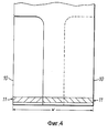
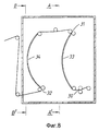
Трубка, показана на фиг. 1, имеет одинаковые внутренние складки 2, глубина которых W в существенной степени равна одной трети ширины трубки с сформированными внутренними складками, и поэтому остается средняя часть 3 трубки шириной w между двумя боковыми частями 4, прилегающими к сформированным внутренним складкам и тоже имеющими ширину w. The tube shown in FIG. 1 has the same
Боковые части 4, прилегающие к внутренним складкам, отгибают относительно соответствующих продольных линий сгиба 5 так, чтобы они были расположены по разные стороны от средней части 3, как показано стрелкой 6 на фиг. 1, так чтобы сложенная трубка приняла конфигурацию, показанную на фиг. 2. Сварной шов 7 выполняют в поперечном направлении на всю ширину сложенной трубки путем прикладывания нагретого ножа, проволоки или бруса к сложенной трубке хорошо известным способом, и как видно из фиг. 2, 10 слоев пленки оказываются сваренными вместе вдоль приблизительно общей длины шва. В альтернативном варианте нагретый нож, проволока или брус могут быть приложены одновременно с каждой стороны трубки. Очень прочный шов может быть получен в результате применения любого из этих способов. The lateral parts 4 adjacent to the inner folds are folded relative to the corresponding longitudinal lines of the fold 5 so that they are located on different sides from the
Испытания показали, что сварной шов не должен иметь выявляемых слабых мест. Tests have shown that the weld should not have detectable weaknesses.
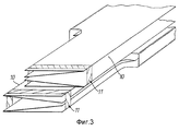
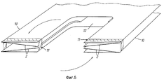
На фиг. 3, 4 и 5 представлен верхний край сумки, которая открыта и снабжена ручками 10, изготовленными путем удаления части сумки, например, с помощью соответствующей операции вырезания. Ручки 10 сформированы на противоположных сторонах трубки 1 с сформированными внутренними складками и имеют ширину меньшую, чем ширина внутренней складки. Предпочтительно, чтобы ширина каждой ручки была в пределах 1/2w - 2/3w, так чтобы, когда сумка находится в сложенном состоянии, ручки были уложены на средней части сложенной сумки. Сварной шов 11 выполняют в поперечном направлении верхним концов ручек путем прикладывания нагретого ножа, проволоки или бруса, способом, аналогичным тому, которым выполнен сварной шов 7, для соединения слоев пластиковой пленки, образующих ручки. Из непрерывной трубки с внутренними складками из пластиковой пленки можно формировать непрерывную цепь сумок с ручками так, чтобы ручки одной сумки были соединены с нижней частью следующей сумки, причем, благодаря созданию перфорации между нижним сварным швом 7 одного сумки и сварным швом ручек 11 следующей сумки, каждую сумку можно легко отделить для ее использования, отрывая сумки вдоль перфорации. На фиг. 5 показан верхний край разложенной сумки, готовой к использованию, с ручками 10 по бокам от горловины 12 сумки. После использования сумки горловину 12 можно закрыть путем завязывания ручек 10 между собой, если это требуется. In FIG. 3, 4 and 5 show the upper edge of the bag, which is open and provided with
На фиг. 6 показаны последовательности операций, которые следует выполнить для изготовления ряда сумок, в соответствии с настоящим изобретением, из вытянутой полиэтиленовой трубки 1. In FIG. 6 shows the sequence of operations that should be performed for the manufacture of a number of bags, in accordance with the present invention, from an
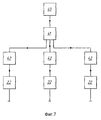
Полиэтиленовую трубку 1 непрерывно выдавливают из экструдера 20 и вытягивают для образования направленной вверх цилиндрической колонны известным способом. Вытянутую трубку протягивают вверх скоростной парой валов через первое складывающее устройство 21, которое одновременно перемещает боковые стороны трубки внутрь для образования внутренних складок 2, как было описано выше, и сплющивают цилиндрическую колонну трубки. В альтернативном варианте вытянутую трубку можно сплющивать и затем формировать внутренние складки способом, известным до настоящего времени. Кроме того, в соответствии с модификацией, представленной на фиг. 7, большую колонну трубки вытягивают из экструдера 40 и сплющивают без внутренних складок. Трубку разрезают и сваривают в продольном направлении с образованием множества, например, трех сплющенных трубок одинаковой ширины. Трубки отделяют одну от другой с помощью ряда роликов 41 и подают к складывающим устройствам 42. Каждую трубку вновь раздувают и формируют внутренние складки способом, аналогичным первому альтернативному варианту, описанному ранее, с помощью складывающего устройства 42. Таким образом, множество параллельных производственных линий может быть запитано от одного экструдера 40. Экструдер 40 и экструдер 20 отличаются только масштабами. В каждом варианте исполнения следующее описание процесса формирования сумок и устройства относится в равной степени к одной производственной линии, показанной на фиг. 6, и к каждой из параллельных производственных линий, показанных на фиг. 7. The
Ручки 10 отдельных сумок, которые должны быть изготовлены из непрерывной трубки, формируют путем выполнения первого сварного шва в поперечном направлении трубки с помощью сварного устройства 22, которое хорошо известным способом налагает нагретый нож так, что слои пленки привариваются друг к другу. Поперечные сварные швы формируют через регулярные интервалы вдоль трубки в соответствии с длиной изготавливаемых сумок. Среднюю часть трубки с внутренними складками, расположенную рядом с каждым сварным швом, затем удаляют с помощью соответствующего устройства для вырезания 23 для образования ручек с каждой стороны трубки с внутренними складками. Следует иметь в виду, что удаленные средние части трубки включают среднюю часть поперечного сварного шва между ручками. Сварочное и режущее устройства 22 и 23 могут быть объединены в одно устройство и/или их порядок расположения может быть изменен на обратный. The
Трубку затем складывают с помощью второго складывающего устройства 24, более подробно описанного ниже. Нижний сварной шов 7 выполняют в поперечном направлении по ширине сложенной сумки, как было описано выше, сварочным устройством 25, и ряд перфораций изготавливают в поперечном направлении по ширине трубки между нижним сварным швом 7 одной сумки и швом 11, скрепляющим ручки, следующей сумки с помощью перфорирующего устройства 26. Сварочное и перфорирующее устройства 25 и 26 могут быть также объединены в одно устройство и/или их последовательность может быть изменена на обратную. Окончательно трубку скатывают в рулон с использованием накатного устройства 27. Отдельные сумки могут быть отделены одна от другой до скатывания в рулон, и скатаны таким образом, чтобы отдельные сумки были уложены внахлест. Рулон сумок может иметь или может не иметь отдельный патрон, например, картонную трубку, в зависимости от конкретных требований потребителя. The tube is then folded using a
В предпочтительной последовательности операций перфорирование более благоприятно производить после завершения складывания сумки, т.е. после второго средства складывания 24 по ходу движения пластиковой трубки, что позволяет протягивать трубку через складывающие устройства и другие аппараты далее за перфорирующим устройством с большей скоростью, чем это могло бы быть возможно в других случаях. In a preferred sequence of operations, it is more advantageous to perforate after folding the bag, i.e. after the second folding means 24 along the direction of movement of the plastic tube, which allows the tube to be pulled through folding devices and other devices further behind the perforating device at a higher speed than would otherwise be possible.
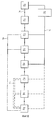
Эталонный сигнал (A), характеризующий линейную скорость, может быть послан датчиком скорости в контроллер 28, который согласует скорости действий сварочного, режущего и складывающих устройств 22, 23 и 24 в единой производственной линии, представленной на фиг. 6, или в каждой из параллельных производственных линий, представленных на фиг. 7. The reference signal (A), characterizing the linear speed, can be sent by the speed sensor to the
Сварочное и режущее устройства 22 и 23 согласуют посредством использования координирующего эталонного сигнала (B), генерируемого первым устройством, расположенным после первого складывающего устройства 21. The welding and cutting
Чувствительный элемент, определяющий наличие отверстия, образующегося в результате удаления сегмента сумки, выполняемого режущим устройством 23, запускает в работу сварочное и перфорационное устройства 25, 26. Предпочтительно, использовать оптический чувствительный элемент для определения наличия отверстия, но может быть применен и любой другой подходящий датчик. A sensing element detecting the presence of an opening resulting from the removal of the bag segment by the cutting
Управление накатным устройством 27 осуществляют с помощью датчика, определяющего наличие перфорации, выполненной перфорирующим устройством 26. Management of the rolling
По выбору, количество сумок, скатанных в рулоны накатным устройством 27, может быть сосчитано с использованием согласующего эталонного сигнала (B), или используя эталонный сигнал (C) непосредственно от устройств 25 или 26. В предпочтительном варианте исполнения управление скоростями сварочного, перфорирующего и накатного устройств 25, 26 и 27 отделено от действия эталонного сигнала скорости (A), но устройствами 25, 26 и 27 можно, в альтернативном варианте, управлять, используя сигнал (A). Optionally, the number of bags rolled up by the
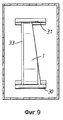
На фиг. 8 - 10 схематически представлено второе складывающее устройство, которое содержит первую и вторую зажимные пары роликов 30, 31 и первый дуговой складывающий клин или укос 33 между ними, и второй дуговой складывающий клин или укос 34, расположенный между второй зажимной парой роликов 31 и третьей зажимной парой роликов 32. Клинья имеют боковые грани, вокруг которых трубу перегибают. Трубка 1 проходит под натяжением между двумя зажимными парами роликов 30 и 31, которые направляют трубку вокруг первого клина 33 так, что одну наружную боковую часть 4 сплющенной трубки укладывают с помощью клина 33 на среднюю часть 3 трубки. Затем трубку пропускают под натяжением относительно клина 34 между второй и третьей зажимными парами роликов 31 и 32, с помощью которых укладывают вторую боковую часть 4 на противоположную сторону средней части, образуя таким образом "сэндвич", в котором средняя часть находится между двумя наружными частями. In FIG. 8-10, a second folding device is shown schematically which comprises a first and second clamping pair of
Натяжение трубки, проходящей относительно складывающих клиньев 33, 34 контролируют путем регулирования скорости зажимных пар роликов 30-32, и регулированием ориентации зажимных пар роликов может быть поддержано одинаковое натяжение по ширине трубки во время ее прохождения относительно клиньев 33, 34. Поддержание одинакового натяжения по ширине трубки позволяет получать удовлетворительное качество складывания, так что каждую из двух боковых частей 4 успешно укладывают на среднюю часть 3. The tension of the tube passing relative to the
Claims (18)
01.05.95 по пп.1 - 3, 6 - 8, 9, 10 - 12, 15 - 17, 18;
08.03.96 по пп.4, 5, 13, 14.Priority on points:
05/01/95 according to claims 1 - 3, 6 - 8, 9, 10 - 12, 15 - 17, 18;
03/08/96 according to paragraphs 4, 5, 13, 14.
Applications Claiming Priority (5)
| Application Number | Priority Date | Filing Date | Title |
|---|---|---|---|
| GBGB9508808.4A GB9508808D0 (en) | 1995-05-01 | 1995-05-01 | Manufacture of bags |
| GBGB9604995.2A GB9604995D0 (en) | 1995-05-01 | 1996-03-08 | Manufacture of bags |
| GB9604995.2 | 1996-03-08 | ||
| GB9508808.4 | 1996-03-08 | ||
| PCT/GB1996/000997 WO1996034737A1 (en) | 1995-05-01 | 1996-04-25 | Manufacture of bags |
Publications (1)
| Publication Number | Publication Date |
|---|---|
| RU2129478C1 true RU2129478C1 (en) | 1999-04-27 |
Family
ID=26306955
Family Applications (1)
| Application Number | Title | Priority Date | Filing Date |
|---|---|---|---|
| RU97119636/12A RU2129478C1 (en) | 1995-05-01 | 1996-04-25 | Bag production method |
Country Status (14)
| Country | Link |
|---|---|
| US (1) | US6254520B1 (en) |
| EP (1) | EP0823876B1 (en) |
| JP (1) | JPH11504276A (en) |
| CN (1) | CN1090082C (en) |
| AU (1) | AU5405496A (en) |
| DE (1) | DE69630028T2 (en) |
| DK (1) | DK0823876T3 (en) |
| ES (1) | ES2207673T3 (en) |
| GB (1) | GB9604995D0 (en) |
| HK (1) | HK1003877A1 (en) |
| PL (1) | PL180692B1 (en) |
| PT (1) | PT823876E (en) |
| RU (1) | RU2129478C1 (en) |
| WO (1) | WO1996034737A1 (en) |
Families Citing this family (10)
| Publication number | Priority date | Publication date | Assignee | Title |
|---|---|---|---|---|
| US7011615B2 (en) * | 1998-01-09 | 2006-03-14 | S.C. Johnson Home Storage, Inc. | Method for making a multicompartment thermoplastic bag |
| US6488222B1 (en) * | 2000-08-18 | 2002-12-03 | Larry G. West | Bag dispensing system and C-fold bag used therewith |
| US20050261119A1 (en) * | 2004-05-18 | 2005-11-24 | Sabrina Pichee Chen | Tri-fold plastic bag roll, method and apparatus for making same |
| US7093978B2 (en) * | 2004-05-20 | 2006-08-22 | Gregorio Lim Tan | Pre-cut plastic bag roll, method and apparatus for making same |
| US7311442B1 (en) | 2004-07-06 | 2007-12-25 | Moravek Lawrence R | Air valve for a fillable poly bag |
| NL1029173C2 (en) * | 2005-06-02 | 2006-12-05 | Smq Group B V | Foldable liner for use in a holder. |
| US9517605B2 (en) | 2012-08-08 | 2016-12-13 | Greg Tan | Tri-fold plastic bag roll, method and apparatus for making same |
| CN103753857B (en) * | 2014-02-21 | 2016-09-07 | 南通捷诺塑胶科技有限公司 | A kind of composite membrane textile folding helps the hole-punching method of stereoscopic bag |
| US10406771B2 (en) * | 2016-06-08 | 2019-09-10 | Miller Weldmaster Corporation | Method and apparatus for producing plastic bags |
| US10717558B2 (en) * | 2016-10-17 | 2020-07-21 | Morrisette Paper Company, Inc. | Machine and process for packaging unique items |
Family Cites Families (13)
| Publication number | Priority date | Publication date | Assignee | Title |
|---|---|---|---|---|
| US3263901A (en) * | 1964-12-23 | 1966-08-02 | Dow Chemical Co | Container of flexible film |
| US3518810A (en) * | 1968-07-26 | 1970-07-07 | Norton Co | Web pleating apparatus and packaged web article |
| DE1934041A1 (en) * | 1969-07-04 | 1971-02-04 | Sengewald Dr Karl H | Method for producing bags or carrier bags with an associated device and carrier bag produced according to the method |
| US3670953A (en) * | 1970-12-10 | 1972-06-20 | Ethyl Corp | Bag |
| DE2428322B2 (en) * | 1974-06-12 | 1976-09-09 | Windmöller & Hölscher, 4540 Lengerich | METHOD AND DEVICE FOR MANUFACTURING SHIRT BAG TOTE BAGS |
| US4386924A (en) * | 1980-10-23 | 1983-06-07 | Fmc Corporation | Handle bag making apparatus |
| US4666423A (en) * | 1985-11-15 | 1987-05-19 | Mobil Oil Corporation | Method of aligning fastener elements on a folded web and device for implementing the method |
| US4923436A (en) * | 1985-11-26 | 1990-05-08 | Sonoco Products Company | Plastic bag and method and apparatus of manufacture |
| DE3613427A1 (en) * | 1986-04-21 | 1987-10-22 | Windmoeller & Hoelscher | METHOD FOR THE PRODUCTION OF SOCIAL SHIRT BAGS |
| US5000728A (en) * | 1987-06-12 | 1991-03-19 | Lemo M. Lehmacher & Sohn Gmbh Maschinenfabrik | Method of and apparatus for stacking bag segments |
| DE4122887C1 (en) * | 1991-07-11 | 1992-09-24 | Lemo M. Lehmacher & Sohn Gmbh, 5216 Niederkassel, De | Prodn. of plastics film bags - with grip strip welded to edges prior to doubling over |
| GB2274446B (en) * | 1993-01-25 | 1996-04-17 | Poly Lina Ltd | Manufacture of bags |
| US5573489A (en) * | 1993-12-22 | 1996-11-12 | Tenneco Plastics Company | Integral handled layflat thermoplastic bag |
-
1996
- 1996-03-08 GB GBGB9604995.2A patent/GB9604995D0/en active Pending
- 1996-04-25 DE DE69630028T patent/DE69630028T2/en not_active Expired - Fee Related
- 1996-04-25 DK DK96911055T patent/DK0823876T3/en active
- 1996-04-25 PL PL96323193A patent/PL180692B1/en not_active IP Right Cessation
- 1996-04-25 ES ES96911055T patent/ES2207673T3/en not_active Expired - Lifetime
- 1996-04-25 WO PCT/GB1996/000997 patent/WO1996034737A1/en active IP Right Grant
- 1996-04-25 JP JP8533101A patent/JPH11504276A/en not_active Ceased
- 1996-04-25 EP EP96911055A patent/EP0823876B1/en not_active Expired - Lifetime
- 1996-04-25 US US08/930,913 patent/US6254520B1/en not_active Expired - Fee Related
- 1996-04-25 CN CN96195025A patent/CN1090082C/en not_active Expired - Fee Related
- 1996-04-25 PT PT96911055T patent/PT823876E/en unknown
- 1996-04-25 RU RU97119636/12A patent/RU2129478C1/en not_active IP Right Cessation
- 1996-04-25 AU AU54054/96A patent/AU5405496A/en not_active Abandoned
-
1998
- 1998-04-20 HK HK98103294A patent/HK1003877A1/en not_active IP Right Cessation
Also Published As
| Publication number | Publication date |
|---|---|
| CN1189123A (en) | 1998-07-29 |
| GB9604995D0 (en) | 1996-05-08 |
| HK1003877A1 (en) | 1998-11-13 |
| PT823876E (en) | 2003-12-31 |
| DE69630028T2 (en) | 2004-04-01 |
| EP0823876B1 (en) | 2003-09-17 |
| DE69630028D1 (en) | 2003-10-23 |
| PL323193A1 (en) | 1998-03-16 |
| WO1996034737A1 (en) | 1996-11-07 |
| PL180692B1 (en) | 2001-03-30 |
| ES2207673T3 (en) | 2004-06-01 |
| EP0823876A1 (en) | 1998-02-18 |
| US6254520B1 (en) | 2001-07-03 |
| AU5405496A (en) | 1996-11-21 |
| DK0823876T3 (en) | 2003-10-20 |
| CN1090082C (en) | 2002-09-04 |
| JPH11504276A (en) | 1999-04-20 |
Similar Documents
| Publication | Publication Date | Title |
|---|---|---|
| US6416452B1 (en) | Method of producing mutliwall plastic bags, especially tie bags | |
| EP2261130B1 (en) | Consumer bags and processes of manufacture and dispensing systems for consumer bags | |
| RU2129478C1 (en) | Bag production method | |
| US5957824A (en) | Bags and method of making bags | |
| US5890810A (en) | Manufacture of bags | |
| JP6804303B2 (en) | Bag webs, and methods for packaging products in film bags by using such bag webs. | |
| CA2394521C (en) | Refuse bags with integral ties and method of manufacture | |
| NL8002089A (en) | METHOD FOR MANUFACTURING A BAG WITH A CARRYING HANDLE | |
| NZ213012A (en) | Forming flat rectangular bottomed gusseted plastics bags | |
| EP1508435B1 (en) | Roll of wave-cut overlapping trash bags and method for producing the same | |
| EP0348823B1 (en) | Method and device for manufacturing bags with thermoplastic pull strings | |
| EP2411203B1 (en) | A process of making bags | |
| JP2756669B1 (en) | How to make bags with headers | |
| NL1007029C2 (en) | Method and device for manufacturing bags. | |
| FR2508020A1 (en) | PLASTIC BAG FOR DOMESTIC USE AND METHOD OF MAKING SAME | |
| JPH0628921B2 (en) | Method and apparatus for manufacturing synthetic resin bag with check | |
| SU728705A3 (en) | Method and apparatus for manufacturing and filling polymeric material bags | |
| US3334552A (en) | Flexible bag of tubular material | |
| EP0257267A2 (en) | Method and device for enveloping objects in a weldable film | |
| NL1004904C2 (en) | Method for manufacturing a chair cover from foil. | |
| NL8002684A (en) | Making bags from folded thermoplastic film printed on two faces - to reduce unit printing cycles and utilise a simple welding unit | |
| CA2170769C (en) | Bags and method of making bags | |
| GB2138353A (en) | Production of bags from an elongate web | |
| JPS62156935A (en) | Method and device for making bag with open-close cord | |
| BE862069A (en) | PLASTIC STORAGE BAG WITH REINFORCED HANDLE AND PROCESS FOR ITS MANUFACTURING |
Legal Events
| Date | Code | Title | Description |
|---|---|---|---|
| MM4A | The patent is invalid due to non-payment of fees |
Effective date: 20050426 |