RU2123951C1 - Guide system for two four-wheel bogies with adjustable wheel-to-wheel cross distance and guide system for four-wheel bogie with adjustable wheel-to-wheel cross distance - Google Patents
Guide system for two four-wheel bogies with adjustable wheel-to-wheel cross distance and guide system for four-wheel bogie with adjustable wheel-to-wheel cross distance Download PDFInfo
- Publication number
- RU2123951C1 RU2123951C1 RU94037586A RU94037586A RU2123951C1 RU 2123951 C1 RU2123951 C1 RU 2123951C1 RU 94037586 A RU94037586 A RU 94037586A RU 94037586 A RU94037586 A RU 94037586A RU 2123951 C1 RU2123951 C1 RU 2123951C1
- Authority
- RU
- Russia
- Prior art keywords
- wheel
- balancer
- trolley
- fork
- frame
- Prior art date
Links
Images
Classifications
-
- B—PERFORMING OPERATIONS; TRANSPORTING
- B61—RAILWAYS
- B61F—RAIL VEHICLE SUSPENSIONS, e.g. UNDERFRAMES, BOGIES OR ARRANGEMENTS OF WHEEL AXLES; RAIL VEHICLES FOR USE ON TRACKS OF DIFFERENT WIDTH; PREVENTING DERAILING OF RAIL VEHICLES; WHEEL GUARDS, OBSTRUCTION REMOVERS OR THE LIKE FOR RAIL VEHICLES
- B61F7/00—Rail vehicles equipped for use on tracks of different width
-
- B—PERFORMING OPERATIONS; TRANSPORTING
- B61—RAILWAYS
- B61F—RAIL VEHICLE SUSPENSIONS, e.g. UNDERFRAMES, BOGIES OR ARRANGEMENTS OF WHEEL AXLES; RAIL VEHICLES FOR USE ON TRACKS OF DIFFERENT WIDTH; PREVENTING DERAILING OF RAIL VEHICLES; WHEEL GUARDS, OBSTRUCTION REMOVERS OR THE LIKE FOR RAIL VEHICLES
- B61F3/00—Types of bogies
- B61F3/16—Types of bogies with a separate axle for each wheel
-
- B—PERFORMING OPERATIONS; TRANSPORTING
- B61—RAILWAYS
- B61F—RAIL VEHICLE SUSPENSIONS, e.g. UNDERFRAMES, BOGIES OR ARRANGEMENTS OF WHEEL AXLES; RAIL VEHICLES FOR USE ON TRACKS OF DIFFERENT WIDTH; PREVENTING DERAILING OF RAIL VEHICLES; WHEEL GUARDS, OBSTRUCTION REMOVERS OR THE LIKE FOR RAIL VEHICLES
- B61F5/00—Constructional details of bogies; Connections between bogies and vehicle underframes; Arrangements or devices for adjusting or allowing self-adjustment of wheel axles or bogies when rounding curves
- B61F5/38—Arrangements or devices for adjusting or allowing self- adjustment of wheel axles or bogies when rounding curves, e.g. sliding axles, swinging axles
- B61F5/44—Adjustment controlled by movements of vehicle body
Abstract
Description
Изобретения касаются конструкций железнодорожных транспортных средств с изменяемым поперечным расстоянием между колесами. The invention relates to the construction of railway vehicles with a variable lateral distance between the wheels.
Известна направляющая система для двух четырехколесных тележек с изменяемым поперечным расстоянием между колесами, содержащая тяги, связанные с тележками и закрепляемые на кузове пассажирского или грузового вагона /SU авторское свидетельство 1245481, кл. B 61 F 5/38, 1986 г./. A known guide system for two four-wheeled trolleys with a variable lateral distance between the wheels, containing traction associated with the trolleys and mounted on the body of a passenger or freight car / SU copyright certificate 1245481, cl. B 61 F 5/38, 1986 /.
Техническим результатом изобретения является улучшение вхождения двух колесных пар каждой тележки в криволинейный участок пути посредством точного направления колесных пар по криволинейному участку пути любого радиуса и устранения динамических нагрузок на тележки с независимо подвешенными колесами. The technical result of the invention is to improve the entry of two wheelsets of each trolley into a curved section of the track by accurately guiding the wheelsets along the curved section of the track of any radius and eliminating dynamic loads on the bogies with independently suspended wheels.
Для достижения этого технического результата направляющая система для двух четырехколесных тележек с изменяемым поперечным расстоянием между колесами, содержащая тяги, связанные с тележками и закрепляемые на кузове пассажирского или грузового вагона, снабжена тремя балансирами, к соответствующему концу одного из которых - центрального, шарнирно закрепляемого в средней части кузова вагона, шарнирно прикреплены одни концы упомянутых тяг, и дополнительными тягами, при этом каждая тележка состоит из центральной рамы, установленных на ней с возможностью поворота вокруг вертикальных осей несущих рам с двумя качающимися вильчатыми рычагами, несущими буксы, выполненные с цилиндрической верхней частью для опирания соответствующего конца вильчатого рычага, выполненных из упругого материала листов, расположенных между соответствующей буксой и каждой вилкой вильчатого рычага, и четырех колесных узлов, каждый из которых выполнен с осью, установленной в буксах с возможностью смещения поперек тележки, тормозными дисками и колесом, закрепленными на оси, причем второй и третий балансиры шарнирно закреплены на центральной раме соответствующей тележки, верхние концы этих балансиров шарнирно соединены с одними концами соответствующих дополнительных тяг, вторые концы которых шарнирно соединены с кронштейнами, закрепляемыми на кузове вагона, а нижние концы этих балансиров шарнирно соединены с одними концами других соответствующих дополнительных тяг, вторые концы которых соединены с корпусом наружной вилки одного вильчатого рычага, шарнирно закрепленного на одной несущей раме, несущей соответствующие колесные узлы, вторые концы тяг и одни концы третьих соответствующих дополнительных тяг посредством общего шарнира соединены с соответствующим вторым или третьим балансиром, вторые концы третьих дополнительных тяг шарнирно соединены с корпусом наружной вилки другого вильчатого рычага, шарнирно закрепленного на другой несущей раме, несущей другие колесные узлы, а упомянутый общий шарнир на каждом из этих балансиров расположен выше оси крепления балансира на соответствующей центральной раме на том же расстоянии от этой оси, что и шарнир крепления нижнего конца каждого балансира с упомянутыми одними концами других соответствующих дополнительных тяг. To achieve this technical result, the guiding system for two four-wheeled trolleys with a variable lateral distance between the wheels, containing traction connected to the trolleys and fixed on the body of a passenger or freight car, is equipped with three balancers, to the corresponding end of one of which is the central one, articulated in the middle the car body parts, one ends of the mentioned rods are pivotally attached, and with additional rods, each trolley consisting of a central frame mounted on with the possibility of rotation around the vertical axes of the supporting frames with two swinging fork levers carrying axle boxes made with a cylindrical upper part for supporting the corresponding end of the fork lever, made of elastic material of sheets located between the corresponding axle box and each fork of the fork lever, and four wheel units, each of which is made with an axle mounted in axle boxes with the possibility of displacement across the trolley, brake discs and a wheel mounted on an axis, the second and third b lansirs are pivotally mounted on the central frame of the corresponding carriage, the upper ends of these balancers are pivotally connected to one ends of the corresponding additional rods, the second ends of which are pivotally connected to brackets fixed to the car body, and the lower ends of these balancers are pivotally connected to one ends of other corresponding additional rods, the second ends of which are connected to the body of the outer fork of one fork lever pivotally mounted on one carrier frame bearing the corresponding wheel the evils, the second ends of the rods and one ends of the third corresponding additional rods are connected by means of a common hinge to the corresponding second or third balancer, the second ends of the third additional rods are pivotally connected to the outer fork body of another fork lever pivotally mounted on another carrier frame carrying other wheel assemblies, and the said common hinge on each of these balancers is located above the axis of fastening of the balancer on the corresponding Central frame at the same distance from this axis as the hinge I am the lower end of each balancer with the mentioned one ends of the other corresponding additional rods.
Кроме того, упомянутые балансиры, закрепленные на центральных рамах соответствующих тележек и в средней части кузова, и соединенные с этими балансирами соответствующие тяги установлены с возможностью поворота при входе пассажирского или грузового вагона в криволинейный участок железнодорожного пути колесных узлов задней тележки на тот же угол, что и колесные узлы передней тележки, а каждая тележка выполнена со спиральными пружинами, образующими подвеску колесных узлов на центральной раме, и резиновыми подкладками, установленными между центральной рамой и несущими рамами и под нижними концами упомянутых пружин с возможностью сдвига при повороте несущих рам вокруг вертикальных осей. In addition, the said balancers, mounted on the central frames of the respective bogies and in the middle part of the body, and the corresponding rods connected to these balancers are mounted with the possibility of rotation at the same angle as the passenger or freight wagon enters the curved section of the railway track of the wheel units of the rear bogie and wheel assemblies of the front carriage, and each carriage is made with coil springs forming a suspension of wheel assemblies on the central frame, and rubber pads mounted between at the central frame and the bearing frames and beneath the lower ends of said springs when rotated to shift the carrier frame about vertical axes.
Известна направляющая система для четырехколесной тележки с изменяемым поперечным расстоянием между колесами, содержащая балансир, тягу, один конец которой шарнирно соединен с верхним концом балансира, а другой - с кронштейном, жестко закрепляемым на раме кузова пассажирского или грузового вагона, вторую тягу, одним концом шарнирно прикрепленную к балансиру, и третью тягу, один конец которой шарнирно соединен с нижним концом балансира /FR 2575429, кл. B 61 F 5/38, 1986 г./. A known guide system for a four-wheeled trolley with a variable lateral distance between the wheels, comprising a balancer, a rod, one end of which is pivotally connected to the upper end of the balancer, and the other with a bracket rigidly mounted on the frame of a passenger or freight car body, a second rod, one end of the articulated attached to the balancer, and a third rod, one end of which is pivotally connected to the lower end of the balancer / FR 2575429, class. B 61 F 5/38, 1986 /.
Для достижения упомянутого технического результата направляющая система для четырехколесной тележки с изменяемым поперечным расстоянием между колесами, содержащая балансир, тягу, один конец которой шарнирно соединен с верхним концом балансира, а другой - с кронштейном, жестко закрепляемым на раме кузова пассажирского или грузового вагона, вторую тягу, одним концом шарнирно прикрепленную к балансиру, и третью тягу, один конец которой шарнирно соединен с нижним концом балансира, снабжена двумя дополнительными балансирами и дополнительными тягами, при этом каждая тележка состоит из центральной рамы, установленных на ней с возможностью поворота вокруг вертикальных осей несущих рам с двумя качающимися вильчатыми рычагами, несущими буксы, выполненные с цилиндрической верхней частью для опирания соответствующего конца вильчатого рычага, выполненных из упругого материала листов, расположенных между соответствующей буксой и каждой вилкой вильчатого рычага, и четырех колесных узлов, каждый из которых выполнен с осью, установленной в буксах с возможностью смещения поперек тележки, тормозными дисками и колесом, закрепленными на оси, причем балансир шарнирно закреплен на центральной раме тележки, первый дополнительный балансир шарнирно прикреплен к корпусу наружной вилки вильчатого рычага, шарнирно закрепленного на несущей раме передней колесной пары тележки, а второй дополнительный балансир шарнирно прикреплен к корпусу наружной вилки вильчатого рычага, шарнирно закрепленного на несущей раме задней колесной пары тележки, второй конец второй тяги шарнирно прикреплен к верхнему концу второго дополнительного балансира, нижний конец которого шарнирно соединен с одним концом первой дополнительной тяги, второй конец которой шарнирно соединен с центральной рамой тележки, второй конец третьей тяги шарнирно соединен с нижним концом первого дополнительного балансира, верхний конец которого шарнирно соединен с одним концом второй дополнительной тяги, второй конец которой шарнирно соединен с центральной рамой тележки. To achieve the aforementioned technical result, a guiding system for a four-wheeled trolley with a variable lateral distance between the wheels, comprising a balancer, a rod, one end of which is pivotally connected to the upper end of the balancer, and the other with a bracket rigidly fixed to the body frame of a passenger or freight car, a second rod , one end pivotally attached to the balancer, and a third rod, one end of which is pivotally connected to the lower end of the balancer, is equipped with two additional balancers and an additional rods, wherein each trolley consists of a central frame mounted on it with the possibility of rotation around the vertical axes of the supporting frames with two swinging fork levers carrying axle boxes made with a cylindrical upper part for supporting the corresponding end of the fork lever made of elastic material of sheets, located between the corresponding axle box and each fork of the fork lever, and four wheel units, each of which is made with an axle mounted in axle boxes with the possibility of displacement across carts, brake discs and a wheel mounted on an axis, and the balancer is pivotally mounted on the central frame of the trolley, the first additional balancer is pivotally attached to the casing of the outer fork of the fork lever pivotally mounted on the supporting frame of the front wheel pair of the trolley, and the second additional balancer is pivotally attached to the body the external fork of the fork lever pivotally mounted on the supporting frame of the rear wheel pair of the trolley, the second end of the second link is pivotally attached to the upper end of the second accessory a balancer, the lower end of which is pivotally connected to one end of the first additional link, the second end of which is pivotally connected to the center frame of the trolley, the second end of the third link is pivotally connected to the lower end of the first additional link, the upper end of which is pivotally connected to one end of the second additional link, the second end of which is pivotally connected to the Central frame of the trolley.
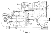
На фиг. 1 - четырехколесная тележка с изменяемым поперечным расстоянием между ее колесами, с которой используется направляющая система, общий вид. In FIG. 1 - four-wheeled trolley with a variable lateral distance between its wheels, with which a guide system is used, general view.
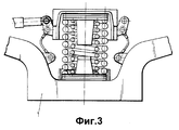
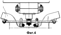
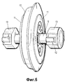
На фиг. 2 - то же, вид сверху. На фиг. 3 - разрез А-А фиг. 2, на фиг. 4 - вид по стрелке Б фиг. 2. На фиг. 5 колесный узел тележки, в аксонометрии. In FIG. 2 - the same, top view. In FIG. 3 is a section AA of FIG. 2, in FIG. 4 is a view along arrow B of FIG. 2. In FIG. 5 wheeled trolley assembly, in perspective view.
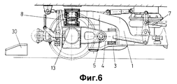
На фиг. 6 - колесный узел, закрепленный в качающемся вильчатом рычаге, общий вид. In FIG. 6 - wheel unit, mounted in a swinging fork lever, general view.
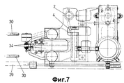
На фиг. 7 - то же, вид сверху. In FIG. 7 - same, top view.
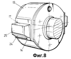
На фиг. 8 - букса. In FIG. 8 - axle box.
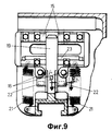
На фиг. 9 - установочные и запирающие элементы буксы, расположенной в корпусе одной вилки качающегося рычага, в разрезе. In FIG. 9 - installation and locking elements of the axle box located in the housing of one fork of the swinging lever, in the context.
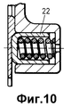
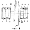
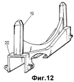
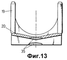
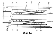
На рис. 10 - разрез B-B фиг. 9. На фиг. 11 - колесный узел, вид спереди с частичным разрезом. На фиг. 12 - запирающее приспособление, в аксонометрии. На фиг. 13 - то же, вид спереди. На фиг. 14 - стационарное путевое устройство для изменения поперечного расстояния между колесами тележки, схематично. In fig. 10 is a section B-B of FIG. 9. In FIG. 11 - wheel unit, front view with a partial section. In FIG. 12 - locking device, in a perspective view. In FIG. 13 is the same front view. In FIG. 14 is a stationary track device for changing the transverse distance between the wheels of the trolley, schematically.
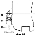
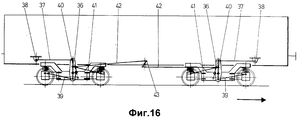
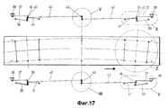
На фиг. 15 - башмак скольжения, опирающийся на центрирующий направляющий рельс, поперечное сечение. На фиг. 16 - направляющая система, используемая с обычным вагоном, общий вид, стрелка показывает направление движения вагона. На фиг. 17 - направляющая система для двух тележек, расположенная с двух боковых сторон вагона. In FIG. 15 - slip shoe, resting on a centering guide rail, cross section. In FIG. 16 is a guide system used with a conventional wagon, general view, an arrow shows the direction of movement of the wagon. In FIG. 17 is a guide system for two trolleys located on two sides of the car.
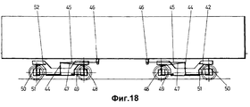
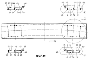
На фиг. 18 - направляющая система для одной тележки вагона, общий вид, схематично. На фиг. 19 - то же, на правостороннем криволинейном участке железнодорожного пути, направление движения показано стрелкой. In FIG. 18 is a guide system for one carriage carriage, a general view, schematically. In FIG. 19 - the same, on the right-hand curved section of the railway track, the direction of movement is shown by an arrow.
Направляющая система используется с четырехколесной тележкой, показанной на фиг. 1 и 2, имеющей изменяемое расстояние между колесами. Тележка является частью этой системы и содержит центральную раму, с которой посредством шарниров и резиновых подкладок 3 соединены две идентичные рамы, несущие колесные узлы. The guide system is used with the four-wheeled cart shown in FIG. 1 and 2, having a variable distance between the wheels. The trolley is part of this system and contains a central frame to which two identical frames carrying wheel assemblies are connected by hinges and
Каждая из рам 4 поворачивается вокруг вертикальной оси шарнира 2, обеспечивая направление двух колесных узлов в криволинейном участке железнодорожного пути. Each of the
С каждой рамой 4 посредством шарнира 5 соединены два вильчатых рычага 6. Two
К концу каждой вилки качающегося рычага 6 прикреплен корпус, в котором расположены букса колесного узла и элементы, освобождающие буксу, так что два колесных узла могут поперечно смещены в положение, в котором расстояние между их колесами соответствует той или иной ширине колеи, и запирающие буксу в смещенных положениях колесных узлов. A housing is attached to the end of each fork of the
Передача вертикальной нагрузки от кузова железнодорожного транспортного средства на центральную раму 1 тележки, а также передача на нее продольных, тормозных и поперечных сил осуществляется через две пневматические рессоры 7 и соответствующие передающие элементы, т.е. через вспомогательную подвеску. The transmission of the vertical load from the body of the railway vehicle to the central frame 1 of the truck, as well as the transmission of longitudinal, braking and transverse forces to it through two
Вместо пневматических рессор 7 могут быть использованы также спиральные пружины, показанные на фиг. 3, 4. Instead of the
Передача вертикальной нагрузки, продольных и поперечных сил от центральной рамы тележки на колесные узлы осуществляется через спиральные пружины 8, показанные на фиг. 1, т.е. через основную подвеску. The vertical load, longitudinal and lateral forces from the central frame of the trolley to the wheel assemblies are transmitted through the
Две направляющие системы, описываемые более подробно ниже, обеспечивают направление в криволинейный участок пути двух тележек со смещаемыми, независимо подвешенными колесами, которыми снабжаются обычный пассажирский или грузовой вагон. Two guide systems, described in more detail below, provide direction to the curved section of the path of two bogies with movable, independently suspended wheels, which are equipped with a regular passenger or freight car.
Работа этих автономных направляющих систем основана на относительном повороте между передней по направлению движения тележкой и кузовом вагона, когда он начинает входить в криволинейный участок пути. The work of these autonomous guiding systems is based on a relative rotation between the front trolley in the direction of movement and the car body when it begins to enter a curved section of the track.
Ввиду симметричности конструкции направляющей системы относительно средней поперечной плоскости кузова железнодорожного транспортного средства ее работа не зависит от направления его движения. Due to the symmetry of the design of the guide system relative to the average transverse plane of the body of a railway vehicle, its operation does not depend on the direction of its movement.
Как уже упоминалось, направляющая система в обоих вариантах ее выполнения может быть использована также для направления в криволинейный участок пути тележек с независимо подвешенными колесами, поперечное расстояние между которыми не изменяется. As already mentioned, the guiding system in both variants of its execution can also be used to direct bogies with independently suspended wheels to the curved section of the path, the transverse distance between which does not change.
Каждая тележка имеет четыре колесных узла, один из которые показан на фиг. 5, и запирающее приспособление для каждого из них. Каждый колесный узел содержит ось, колесо 10, тормозные диски 11 буксы 12, закрепленные на концах оси. Each trolley has four wheeled units, one of which is shown in FIG. 5, and a locking device for each of them. Each wheel assembly contains an axle, a
Каждая букса 12 /фиг. 5 и 8/ имеет в верхней части цилиндрическую поверхность 13, на которую обычно опирается конец соответствующей вилки качающегося рычага 6, как это видно на фиг. 6 и 7. Each
Для более равномерного распределения нагрузки по опорной поверхности буксы между последней и вилкой рычага 6 может быть расположен лист, выполненный из упругого материала, который прочно крепится к поверхности буксы или рычагу 6. To more evenly distribute the load on the bearing surface of the axle box between the last and the fork of the
Таким образом, обеспечивается вертикальное положение между буксами и каждым вильчатым качающимся рычагом. This ensures a vertical position between the axle boxes and each fork tilting lever.
Для лучшего понимания настоящего изобретения необходимо помнить, что продольные смещения элементов параллельны железнодорожному пути, а горизонтальные поперечные смещения перпендикулярны этому пути. For a better understanding of the present invention, it is necessary to remember that the longitudinal displacements of the elements are parallel to the railway track, and the horizontal transverse displacements are perpendicular to this track.
Каждая букса имеет переднюю и заднюю плоские вертикальные поверхности 14 /фиг. 8/, которые находятся в контакте с соответствующими плоскими вертикальными поверхностями вставок 15 и 16 /фиг. 9/ и перемещаются по ним. Each axle box has front and rear flat
Между корпусом каждой буксы и соответствующим концом оси колесного узла расположена упругая втулка, так что буксы имеют небольшую степень свободы, чтобы компенсировать их отклонение от соосности, которая необходима для передачи поперечных сил на соответствующий вильчатый качающийся рычаг во время движения транспортного средства. An elastic sleeve is located between the body of each axle box and the corresponding end of the axle of the wheel assembly, so that the axle boxes have a small degree of freedom in order to compensate for their deviation from the alignment, which is necessary for the transverse forces to be transmitted to the corresponding fork swinging arm while the vehicle is moving.
Каждая букса имеет также выступы 17 на передней и задней вертикальных поверхностях 14 /фиг. 8/, которые выполнены за одно целое с ней и являются поперечными крепежными элементами для нее. Each axle box also has
Между упорами 18 и 53, которыми снабжены корпуса вилок качающихся рычагов /фиг. 11/, расположены запирающие стержни 19 для предотвращения поперечного смещения букс относительно соответствующих корпусов. Between the
Расстояние между двумя вертикальными поверхностями каждого выступа 17 буксы, с которыми контактируют запирающие стержни, равно половине разности ширины первой и второй колеи минус толщина стержня 19. The distance between the two vertical surfaces of each
Стержни жестко соединены между собой посредством перемычки 20 /фиг. 12/, которая вместе с ними образует запирающее ее приспособление. Стержни перемещаются вверх и вниз между продольными вертикальными поверхностями вставок 15 и 16 /фиг. 9/, жестко закрепленных в корпусе каждой линии качающегося рычага 6. The rods are rigidly interconnected by means of a
Следовательно, каждое запирающее приспособление может перемещаться только в вертикальном направлении, в любом другом направлении его перемещение предотвращается жесткими упорами. Therefore, each locking device can only move in the vertical direction, in any other direction its movement is prevented by rigid stops.
Запирающее приспособление удерживается в поднятом рабочем положении с помощью пружин 21, показанных на фиг. 9, величина предварительного натяжения которых больше его массы, и дополнительного удерживающего приспособления 22 /фиг. 2/. The locking device is held in a raised operating position by means of the
Перемычка 20 запирающего приспособления выполнена такой, что в нее может входить Т-образная верхняя часть одной из направляющих упомянутого стационарного путевого устройства, чтобы переместить запирающее приспособление вниз, преодолевая трение и усилие предварительно натянутых пружин 21 и дополнительного удерживающего приспособления 22. The
Перемычка имеет криволинейную внутреннюю поверхность, так что самоустанавливается на наклонных поверхностях упомянутой направляющей стационарного путевого устройства, с помощью которого изменяется поперечное расстояние между колесами тележки. The jumper has a curved inner surface, so that it is self-mounted on the inclined surfaces of the aforementioned guide of the stationary traveling device, with which the lateral distance between the wheels of the trolley is changed.
Конструкция запирающего приспособления показана на фиг. 12 и 13. The design of the locking device is shown in FIG. 12 and 13.
Вставки 15 и 16, показанные на фиг. 9, закреплены на вертикальных стенках корпуса каждой вилки качающегося рычага 6 и выполняют роль поперечных упоров для запирающих стержней 19. Вставки имеют вертикальные поперечные поверхности, по которым продольно перемещаются вертикальные поверхности 14 каждой буксы. The
Вставка 16 /фиг. 9/ имеет поперечную направляющую 23 с наклонной верхней поверхностью, по которой перемещается букса во время поперечного смещения колесного узла.
Нижняя поверхность 24 каждого выступа 17 буксы имеет тот же угол наклона, что и верхняя поверхность этой направляющей и обычно располагается на некотором расстоянии от нее. The
Когда тележка вывешивается, буксы 12 опускаются, так, что нижние поверхности 24 их выступов 17 опираются на верхние наклонные поверхности направляющих 23, по которым они перемещаются во время поперечного смещения колесных узлов. When the trolley is hung out, the
Благодаря тому, что верхние поверхности направляющих 23 имеют наклон, на них предотвращается скапливание инородных тел во время движения транспортного средства, которые могли бы препятствовать поперечному смещению колес при изменении расстояния между ними. Due to the fact that the upper surfaces of the
На нижних наклонных поверхностях 24 выступов букс закреплены накладки, выполненные из металлокерамического материала, имеющего небольшой коэффициент трения скольжения и высокий предел прочности на сжатие, чтобы облегчить поперечное смещение колесных узлов для возможности их расположения на колее той или иной ширины. On the lower inclined surfaces of the 24 ledges of the axle boxes, pads made of cermet material having a small coefficient of sliding friction and a high compressive strength are fixed to facilitate lateral displacement of the wheel assemblies for the possibility of their location on a track of one or another width.
К вертикальной поперечной поверхности 25 /фиг. 8/ выступов 17 букс крепится опора 26 (фиг. 2), несущая тормозной цилиндр, который через рычажную передачу перемещает тормозные накладки. To the vertical
Жесткость качающихся вильчатых рычагов 6, несущих колесные узлы, обеспечивает параллельность колес, когда они располагаются на колее той или иной ширины и подвергаются вертикальным или поперечным нагрузкам во время движения вагона. The stiffness of the swinging
Изменение поперечного расстояния между колесами тележек для возможности движения транспортного средства по железнодорожной колее другой ширины осуществляется с помощью стационарного путевого устройства, расположенного на транзитной железнодорожной станции. Changing the transverse distance between the wheels of the bogies to allow the vehicle to move along a railway track of a different width is carried out using a stationary track device located at the transit railway station.
При изменении поперечного расстояния между колесами тележек транспортное средство перемещается через путевое устройство с пониженной скоростью /до 15 км/час/. When changing the transverse distance between the wheels of the bogies, the vehicle moves through the track device at a reduced speed / up to 15 km / h /.
Для лучшего понимания этой операции на фиг. 14 схематично показаны элементы, образующие путевое устройство, которыми являются:
- конечный участок 27 широкой железнодорожной колеи.For a better understanding of this operation, FIG. 14 schematically shows the elements forming the track device, which are:
- the
- конечный участок 28 более узкой железнодорожной колеи. -
- центрирующие направляющие рельсы 29. - centering guide rails 29.
- направляющие 30 для отпирания и запирания букс колесных узлов тележки. - guides 30 for unlocking and locking the axle boxes of the trolley wheel assemblies.
- направляющие для поперечного смещения колесных узлов, состоящие из упругих 31 и жестких 32 частей. - guides for lateral displacement of the wheel assemblies, consisting of elastic 31 and hard 32 parts.
Предположим, что вагон затаскивается на стационарное путевое устройство со стороны широкой железнодорожной колеи, левая сторона на фиг. 14. Процесс изменения поперечного расстояния между колесами тележек вагона заключается в перемещении последнего следующим образом. Assume that the carriage is pulled onto a stationary track device from the wide gauge side, the left side in FIG. 14. The process of changing the transverse distance between the wheels of the wagon trolleys is to move the latter as follows.
Для поперечного смещения колесных узлов необходимо снять нагрузку с колес. For lateral displacement of the wheel assemblies, it is necessary to remove the load from the wheels.
Это достигается за счет расположения тележки на центрирующих направляющих рельсах 29. Когда тележка перемещается по конечному участку 27 широкой колеи, имеющему наклон вниз, башмаки скольжения 33, закрепленные на ней /фиг. 15/, постепенно опускаются до тех пор, пока они не начнут опираться на соответствующий направляющий рельс 29. This is achieved due to the location of the trolley on the centering guide rails 29. When the trolley moves along the
Для обеспечения большей опорной поверхности башмаков 33 в начальный момент их контакта с направляющими рельсами 29 опорная часть 54 каждого башмака соединена с его несущей частью 55 посредством шарового шарнира. To ensure a larger bearing surface of the shoes 33 at the initial moment of their contact with the guide rails 29, the supporting
Башмаки и центрирующие направляющие рельсы выполнены из пластика и к поверхностям их контакта подводится жидкая смазка, в качестве которой используется вода, чтобы получить низкий коэффициент трения при скольжении башмаков по этим рельсам. The shoes and the centering guide rails are made of plastic and liquid lubricant is supplied to their contact surfaces, which is used as water, in order to obtain a low coefficient of friction when the shoes slide along these rails.
Преимущество такой жидкой смазки перед другими смазками заключается в том, что вода не вызывает "сцепления" - контактных поверхностей и их загрязнения. The advantage of such a liquid lubricant over other lubricants is that water does not cause “adhesion” - contact surfaces and their contamination.
После разгрузки колесных узлов их буксы необходимо "освободить" от запирающих приспособлений. After unloading the wheel assemblies, their axle boxes must be "released" from the locking devices.
С этой целью стационарное путевое устройство имеет четыре направляющих 30 для отпирания и запирания букс 12 /фиг. 14/, которые расположены вдоль его продольной оси. For this purpose, the stationary track device has four
Верхняя часть направляющих 30 имеет Т-образное поперечное сечение и криволинейный вертикальный профиль /фиг. 6/ и входит в перемычки 20 запирающих приспособлений, которые опускаются, освобождая буксы, когда они перемещаются по участку направляющих 30, имеющему наклон вниз. Запирающие приспособления удерживаются в опущенном положении на центральном горизонтальном участке направляющих 30. The upper part of the
Поскольку фрикционные части 35 перемычек запирающих приспособлений /фиг. 13/ выполнены из пластика, к ним также подводится жидкая смазка, в качестве которой используется вода. Since the
Во время опускания запирающих приспособлений, т.е. во время освобождения или отпирания букс, внутренние поверхности колес входят в контакт с упругими частями 31 направляющих для поперечного смещения колесных узлов, которые прикладывают к внутренним поверхностям давление, содействуя отпиранию букс. While lowering the locking devices, i.e. during the release or unlocking of the axleboxes, the inner surfaces of the wheels come into contact with the
После снятия нагрузки с колес и перед отпиранием букс колесные узлы немного опускаются, так что наклонные поверхности 24 выступов 17 букс опираются на наклонную верхнюю поверхность направляющих 23. After removing the load from the wheels and before unlocking the axle boxes, the wheel assemblies are lowered a little, so that the
При дальнейшем перемещении тележки вперед через путевое устройство ее колеса выходят из контакта с упругими частями 31, расположенными рядом с широкой колеей, и входят в контакт с жесткими частями 32 упомянутых направляющих, при этом запирающие приспособления удерживаются в опущенном положении, так что колеса каждой колесной пары смещаются в направлении друг к другу в положение, в котором поперечное расстояние между ними соответствует ширине более узкой колеи 28. With further movement of the trolley forward through the track device, its wheels come out of contact with the
Когда колеса входят в контакт с упругими частями 31, расположенными рядом с более узкой колеей, запирающие приспособления поднимаются и запирают буксы, а следовательно, и колеса, в положении, в котором расстояние между последними соответствует ширине более узкой колеи. When the wheels come into contact with the
При дальнейшем движении вперед разгруженные колеса начинают перемещаться по конечному участку более узкой железнодорожной колеи 28, который имеет наклон вверх, вследствие чего башмаки 33 тележки постепенно поднимаются от центрирующих направляющих рельсов 29, так что колеса нагружаются, и тележка подготовлена для перемещения по узкой железнодорожной колее. With further forward movement, the unloaded wheels begin to move along the final section of the
Процесс перевода железнодорожного транспортного средства с более узкой колеи на более широкую осуществляется аналогичным образом. The process of moving a railway vehicle from a narrower track to a wider one is carried out in a similar way.
Направляющая система, являющаяся объектом настоящего изобретения, выполняет следующие три функции;
- улучшает прохождение двух колесных пар каждой тележки железнодорожного транспортного средства через кривую пути посредством их точного направления в кривую любого радиуса кривизны, под термином колесная пара следует понимать узел, состоящий из двух отдельных колес и букс, соединенных с несущей рамой 4, показанной на фиг. 1.The guiding system that is the subject of the present invention has the following three functions;
- improves the passage of two wheelsets of each truck of a railway vehicle through the path curve by means of their exact direction to the curve of any radius of curvature, the term wheelset should be understood as a unit consisting of two separate wheels and axle boxes connected to the supporting
- Содействует устранению динамических нагрузок на тележки с независимо подвешенными колесами. - Helps eliminate dynamic loads on trolleys with independently suspended wheels.
- Уменьшает износ обода железнодорожного колеса, в частности его реборды. - Reduces wear on the rim of the railway wheel, in particular its flanges.
Первый вариант исполнения направляющей системы схематично показан на фиг. 16. На этом рисунке направляющая система расположена только с одной боковой стороны пассажирского или грузового вагона. Однако понятно, что такая же направляющая система расположена и на другой боковой стороне вагона. A first embodiment of the guide system is shown schematically in FIG. 16. In this figure, the guide system is located on only one side of a passenger or freight wagon. However, it is understood that the same guide system is also located on the other side of the car.
Направляющая система, расположенная с каждой боковой стороны вагона, является общей для двух его тележек и содержит балансир, шарнирно закрепленный на центральной раме каждой тележки, показанной на фиг. 1, тягу 37, один конец которой шарнирно соединен с верхним концом балансира, а другой с кронштейном 38, закрепленным на кузове пассажирского или грузового вагона, тягу 39, один конец которой шарнирно соединен с нижним концом балансира, а другой с корпусом наружной вилки качающегося рычага 6 /фиг. 1/, соединенного с рамой 4 /фиг. 1/, несущей колесные узлы, и тяги 41, 42, одни концы которых посредством шарнира 40 соединены с балансиром 36. A guide system located on each side of the car is common to its two trolleys and comprises a balancer pivotally mounted on the central frame of each trolley shown in FIG. 1,
Шарнир 40 расположен выше оси поворота балансира 36 на том же расстоянии, что и шарнир, соединяющий один конец тяги 39 с нижним концом балансира, но с противоположной стороны от оси поворота последнего. The
Другой конец тяги 41 шарнирно прикреплен к корпусу наружной вилки другого качающегося рычага 6, который расположен на той же стороне тележки, но соединен с другой ее рамой 4, несущей другие колесные узлы. The other end of the
Все упомянутые элементы направляющей системы не показаны на фиг. 1. All said elements of the guide system are not shown in FIG. one.
Другой конец тяги 42 шарнирно соединен с верхним или нижним концом центрального балансира 43, шарнирно закрепленного в средней части рамы кузова пассажирского или грузового вагона. The other end of the
На фиг. 16 показано положение элементов направляющей системы, общей для двух тележек, когда пассажирский или грузовой вагон входит в правостороннюю кривую железнодорожного пути, направление движения вагона показано стрелкой. На фиг. 17 схематично показано положение элементов направляющей системы, общей для двух тележек, расположенной с каждой боковой стороны вагона, когда последний находится на прямом и кривом участках железнодорожного пути. In FIG. 16 shows the position of the elements of the guide system common to two bogies, when a passenger or freight wagon enters the right-hand curve of the railway track, the direction of movement of the wagon is shown by an arrow. In FIG. 17 schematically shows the position of the elements of the guide system common to two bogies located on each side of the car when the latter is on the straight and curved sections of the railway track.
Когда пассажирский или грузовой вагон входит в криволинейный участок пути, происходит относительный поворот между его тележкой и кузовом. When a passenger or freight wagon enters a curved section of the track, a relative rotation occurs between its trolley and the body.
Вертикальная ось такого поворота проходит через точку P /фиг. 2/. The vertical axis of this rotation passes through the point P / Fig. 2 /.
Допустим, что пассажирский или грузовой вагон движется в направлении стрелки /фиг. 16/ и входит в правосторонний криволинейный участок пути, при этом его передняя тележка будет постепенно поворачиваться вдоль этого участка, так что шарнир, посредством которого балансир 36 закрепляется на центральной раме 1 /фиг. 1/ передней тележки, будет смещаться назад, как это видно на фиг. 17, при этом балансир поворачивается вокруг шарнира, соединяющего его верхний конец с концом тяги 37. Assume that a passenger or freight wagon moves in the direction of the arrow / FIG. 16 / and enters the right-hand curved section of the path, while its front trolley will gradually rotate along this section, so that the hinge through which the
Поворот балансира 36 вызывает соответствующее перемещение тяг 41 и 39, что приводит к повороту обеих рам 4, вследствие чего значительно улучшается вхождение колес в криволинейный участок железнодорожного пути. The rotation of the
Новое положение геометрической оси колес показано на центральном схематическом изображении на фиг. 17, которое соответствует виду сверху на вагон. The new position of the geometric axis of the wheels is shown in the central schematic diagram of FIG. 17, which corresponds to the top view of the car.
При повороте двух рам 4 вокруг вертикальной оси шарнира 2, резиновые подкладки, расположенные под нижними концами спиральных пружин 8, т.е. под основной подвеской, и резиновые подкладки 3 сдвигаются, при этом тяги 39, 41 и 42 смещаются. When two
Смещение тяги 42 при повороте балансира 36 вызывает поворот центрального балансира 43, который в свою очередь перемещает другую тягу 42. The displacement of the
Перемещение тяги 42 вызывает аналогичный поворот балансира 36 задней тележки, вследствие чего колесные пары этой тележки поворачиваются на тот же угол, что и колесные пары передней тележки. The movement of the
Из вышеописанного следует, что направляющая система, общая для обеих тележек вагона, обеспечивает поворот их колесных пар по одной дуге и работает автономно, т.е. не требует ее соединения с направляющей системой других вагонов или с локомотивом. From the above it follows that the guide system, common to both carriages of the car, ensures the rotation of their wheelsets along one arc and works autonomously, i.e. It does not require its connection with the guide system of other cars or with a locomotive.
Во втором варианте исполнения направляющая система является независимой для каждой тележки железнодорожного транспортного средства, в частности для тележки железнодорожного вагона. Независимая направляющая система, расположенная с одной стороны каждой тележки, схематично показана на фиг. 18. Понятно, что такая же независимая направляющая система расположена и с противоположной стороны каждой тележки. In a second embodiment, the guide system is independent for each trolley of a railway vehicle, in particular for a trolley of a railway carriage. An independent guide system located on one side of each trolley is shown schematically in FIG. 18. It is understood that the same independent guide system is also located on the opposite side of each trolley.
Независимая направляющая система содержит первый балансир 44, шарнирно закрепленный на центральной раме 1 тележки, и первую тягу 45, один конец которой шарнирно соединен с верхним концом этого балансира, а другой - с кронштейном 46, жестко закрепленным на кузове пассажирского или грузового вагона. The independent guiding system comprises a
С верхним концом первого балансира 44 шарнирно соединен также один конец второй тяги 47, противоположный конец которой шарнирно соединен с верхним концом второго балансира 48, который в свою очередь шарнирно прикреплен к корпусу наружной вилки качающегося рычага 6, шарнирно соединенного с рамой 4 тележки, несущей заднюю колесную пару. One end of the
С нижним концом второго балансира 48 шарнирно соединен один конец третьей тяги 49, другой конец которой шарнирно соединен с центральной рамой 1 тележки. One end of the
С нижним концом первого центрального балансира 44 шарнирно соединен один конец четвертой тяги 51, другой конец которой шарнирно соединен с нижним концом третьего балансира 50. One end of the
Третий балансир 50 шарнирно прикреплен к корпусу наружной вилки качающегося рычага 6, шарнирно соединенного с рамой 4 тележки, несущей переднюю колесную пару. The
С верхним концом третьего балансира шарнирно соединен один конец пятой тяги 52, другой конец которой шарнирно соединен с центральной рамой 1 тележки. One end of the
На фиг. 19 схематично показано положение элементов независимой направляющей системы, расположенной с двух боковых сторон каждой тележки вагона, когда последний находится на прямом и кривом участках железнодорожного пути. In FIG. 19 schematically shows the position of the elements of an independent guide system located on the two sides of each carriage of the car when the latter is on the straight and curved sections of the railway track.
Когда пассажирский или грузовой вагон входит в кривую пути, происходит относительный поворот между его тележкой и кузовом. When a passenger or freight wagon enters a curved path, a relative rotation occurs between its wagon and body.
Вертикальная ось такого поворота проходит через точку P /фиг. 2/, т.е. так же как и у направляющей системы в первом варианте исполнения. The vertical axis of this rotation passes through the point P / Fig. 2 /, i.e. as well as the guide system in the first embodiment.
Допустим, что пассажирский или грузовой вагон движется в направлении стрелки /фиг. 19/ и входит в правостороннюю кривую пути, при этом его передняя тележка будет постепенно поворачиваться вдоль кривой, так что шарнир, посредством которого балансир 44 закрепляется на центральной раме 1 передней тележки, будет смещаться назад, при этом балансир поворачивается вокруг шарнира, соединяющего его верхний конец с концом тяги 45, другой конец которой шарнирно соединен с кронштейном 46, жестко закрепленным на раме кузова пассажирского или грузового вагона. Assume that a passenger or freight wagon moves in the direction of the arrow / FIG. 19 / and enters the right-hand curve of the path, while its front trolley will gradually rotate along the curve, so that the hinge through which the
Когда балансир поворачивается, его нижний конец перемещает тягу 51, которая в свою очередь перемещает нижний конец балансира 50, при этом верхний конец балансира 50 перемещается с помощью тяги 52, поскольку шарнир 53, посредством которого ее задний конец соединяется с центральной рамой 1 передней тележки, смещается назад в результате поворота тележки относительно кузова вагона. When the balancer rotates, its lower end moves the
При смещении назад верхнего и нижнего концов балансира 50 шарнир, посредством которого он крепится к корпусу наружной вилки качающегося рычага 6, шарнирно соединенного с рамой 4, несущей переднюю колесную пару тележки, также смещается назад, вследствие чего рама 4 поворачивается, что значительно улучшает вхождение или направление колес этой пары в криволинейный участок железнодорожного пути. When the upper and lower ends of the
Аналогичным образом, смещение шарнира 54 назад в результате относительного поворота между передней тележкой и кузовом вагона вызывает смещение назад тяги 49, которая в свою очередь смещает назад нижний конец балансира 48, шарнирно соединенного с тягой 47, которая является неподвижной, при этом балансир 48 поворачивается вокруг шарнира, соединяющего его верхний конец с тягой 47. Similarly, shifting the
При повороте балансира 48 и смещение назад его нижнего конца шарнир, посредством которого он крепится к корпусу наружной вилки качающегося рычага 6, шарнирно соединенного с рамой 4, несущей заднюю колесную пару передней тележки, также смещается назад, вследствие чего эта рама 4 поворачивается, что значительно улучшает направление колес задней пары по криволинейному участку железнодорожного пути. When the
Работа направляющей системы для задней тележки вагона аналогична работе направляющей системы для передней тележки вагона и по этой причине не описывается. The operation of the guide system for the rear carriage of a car is similar to the operation of the guide system for the front carriage of a car and is therefore not described.
Направляющая система для передней и задней по направлению движения вагона колесных пар каждой тележки является идентичной. The guiding system for the front and rear wheelsets of each carriage in the direction of movement of the car is identical.
На центральном схематическом изображении на фиг. 19, которое соответствует виду сверху на вагон, показано положение геометрической оси колесных пар тележек, когда вагон находится на криволинейном участке железнодорожного пути. In the central schematic diagram of FIG. 19, which corresponds to the top view of the wagon, shows the position of the geometric axis of the wheelsets of the bogies when the wagon is on a curved section of a railway track.
Как и для предыдущей направляющей системы направление движения вагона не влияет на работу независимой направляющей системы, которая также является автономной, т.е. не требуют ее соединения с направляющей системой других вагонов. As for the previous guide system, the direction of movement of the car does not affect the operation of an independent guide system, which is also autonomous, i.e. do not require its connection with the guide system of other cars.
Claims (4)
дополнительного балансира, нижний конец которого шарнирно соединен с одним концом первой дополнительной тяги, второй конец которой шарнирно соединен с центральной рамой тележки, второй конец третьей тяги шарнирно соединен с нижним концом первого дополнительного балансира, верхний конец которого шарнирно соединен с одним концом второй дополнительной тяги, второй конец которой шарнирно соединен с центральной рамой тележки.4. A guide system for a four-wheeled trolley with variable lateral distance between the wheels, comprising a balancer, a rod, one end of which is pivotally connected to the upper end of the balancer, and the other with a bracket rigidly fixed to the body frame of a passenger or freight car, a second rod, one end pivotally attached to the balancer, and a third rod, one end of which is pivotally connected to the lower end of the balancer, characterized in that it is provided with two additional balancers and additional rods, each the trolley consists of a central frame mounted on it with the possibility of rotation around the vertical axes of the bearing frames with two swinging fork arms carrying axle boxes made with a cylindrical upper part for supporting the corresponding end of the fork lever made of elastic material of sheets located between the respective axle box and each fork fork lever, and four wheel assemblies, each of which is made with an axle mounted in axle boxes with the possibility of displacement across the trolley, brake discs and a wheel mounted on an axis, wherein the balancer is pivotally mounted on the central frame of the trolley, the first additional balancer is pivotally attached to the body of the outer fork of the fork lever pivotally mounted on the supporting frame of the front wheel pair of the trolley, and the second additional balancer is pivotally attached to the body of the outer fork of the fork lever pivotally mounted on the supporting frame of the rear wheel pair of the trolley, the second end of the second link is pivotally attached to the upper end of the second
an additional balancer, the lower end of which is pivotally connected to one end of the first additional link, the second end of which is pivotally connected to the center frame of the trolley, the second end of the third link is pivotally connected to the lower end of the first additional link, the upper end of which is pivotally connected to one end of the second additional link, the second end of which is pivotally connected to the Central frame of the trolley.
Applications Claiming Priority (2)
| Application Number | Priority Date | Filing Date | Title |
|---|---|---|---|
| ES09302168A ES2084551B1 (en) | 1993-10-15 | 1993-10-15 | GUIDING SYSTEM APPLICABLE TO A FOUR-WHEEL BOGIE WITH VARIBAL SEPARATION BETWEEN THE SAME. |
| ES9302168 | 1993-10-15 |
Publications (2)
| Publication Number | Publication Date |
|---|---|
| RU94037586A RU94037586A (en) | 1996-08-10 |
| RU2123951C1 true RU2123951C1 (en) | 1998-12-27 |
Family
ID=8283327
Family Applications (1)
| Application Number | Title | Priority Date | Filing Date |
|---|---|---|---|
| RU94037586A RU2123951C1 (en) | 1993-10-15 | 1994-10-14 | Guide system for two four-wheel bogies with adjustable wheel-to-wheel cross distance and guide system for four-wheel bogie with adjustable wheel-to-wheel cross distance |
Country Status (18)
| Country | Link |
|---|---|
| EP (1) | EP0648659B1 (en) |
| JP (1) | JP2837098B2 (en) |
| CN (1) | CN1114617A (en) |
| AT (1) | ATE175161T1 (en) |
| AU (1) | AU683686B2 (en) |
| DE (1) | DE69415626T2 (en) |
| DK (1) | DK0648659T3 (en) |
| ES (1) | ES2084551B1 (en) |
| FI (1) | FI944844A (en) |
| GR (1) | GR3029814T3 (en) |
| HU (1) | HUH3883A (en) |
| LT (1) | LT3580B (en) |
| PL (2) | PL175366B1 (en) |
| RO (1) | RO115345B1 (en) |
| RU (1) | RU2123951C1 (en) |
| SI (1) | SI0648659T1 (en) |
| SK (1) | SK125394A3 (en) |
| TR (1) | TR28161A (en) |
Cited By (3)
| Publication number | Priority date | Publication date | Assignee | Title |
|---|---|---|---|---|
| RU189633U1 (en) * | 2019-02-22 | 2019-05-29 | Общество с ограниченной ответственностью "Уральские локомотивы" | CUTTER BAR POSITION REGULATOR |
| RU199816U1 (en) * | 2020-07-06 | 2020-09-21 | Акционерное общество «Научно-производственная корпорация Уралвагонзавод» имени Ф.Э. Дзержинского» | Composite spring suspension of a bogie of a freight railway car |
| RU199813U1 (en) * | 2020-07-06 | 2020-09-21 | Акционерное общество «Научно-производственная корпорация «Уралвагонзавод» имени Ф.Э. Дзержинского» | Composite spring suspension of a bogie of a freight railway car |
Families Citing this family (16)
| Publication number | Priority date | Publication date | Assignee | Title |
|---|---|---|---|---|
| ES2133224B1 (en) * | 1996-08-14 | 2000-04-16 | Talgo Patentes | "BOGIE TRACTOR WITH BUILT-IN WIDTH CHANGE SYSTEM" |
| ES2212154T3 (en) * | 1997-02-10 | 2004-07-16 | Sumitomo Metal Industries, Ltd. | INTERCHANGEABLE WIDTH BOGIE FOR A FRAME. |
| ES2178522B1 (en) * | 1999-07-20 | 2004-09-01 | Alstom Transporte, S.A. | PERFECTION IN CONVENTIONAL MOTOR BOGIES WITH ADAPTATION TO DIFFERENT WAYS OF THE ROAD (WITH POSSIBLE APPLICATION TO TRAILERS). |
| ES2184538B2 (en) * | 1999-10-05 | 2005-05-01 | Construcciones Y Auxiliar De Ferrocarriles, S.A. -Caf- | VARIABLE WIDTH BEARING BOGIE. |
| DE10208542A1 (en) * | 2002-02-27 | 2003-09-04 | Siemens Ag | Lane change chassis for rail vehicles (keyword: swing arm guide) |
| US20050183625A1 (en) * | 2004-02-23 | 2005-08-25 | Goding David J. | High efficiency semi-articulated railway power bogie |
| FR2874883A1 (en) * | 2004-09-07 | 2006-03-10 | Henri Guillemaut | BOGIE, FOR RAILWAY VEHICLES, WITH ORIENTABLE WHEELS ACCORDING TO THE CURVATURE |
| ES2316220B1 (en) | 2006-02-24 | 2010-01-12 | Patentes Talgo, S.L. | METHOD FOR OPTIMIZING GUIDANCE OF RAILWAY VEHICLES. |
| ES2346945B1 (en) * | 2008-04-29 | 2011-12-23 | Patentes Talgo, S.L. | VARIABLE WIDTH BOGIE WITH ROTATING AXLES AND FIXED INSTALLATION FOR VIA WIDTH CHANGE. |
| CN103786742A (en) * | 2012-10-29 | 2014-05-14 | 安海燕 | Mountain climbing rail vehicle steering waist turning type connection |
| CN103121456A (en) * | 2013-03-06 | 2013-05-29 | 唐山轨道客车有限责任公司 | Steering frame for railway vehicle and railway vehicle |
| CN108128321B (en) * | 2017-12-21 | 2019-11-15 | 大连交通大学 | Hub-type independent wheel bogie |
| CN108423027B (en) * | 2018-03-16 | 2019-07-12 | 中车青岛四方车辆研究所有限公司 | Follower and brake clamp unit for gauge-changeable bogie |
| CN108909358B (en) * | 2018-07-05 | 2021-09-10 | 中车青岛四方机车车辆股份有限公司 | Variable-gauge wheel set and variable-gauge bogie |
| CN108909359B (en) * | 2018-07-05 | 2021-06-25 | 中车青岛四方机车车辆股份有限公司 | Axle box body structure for track-pitch-variable wheel set and track-pitch-variable wheel set |
| CN217002455U (en) * | 2021-10-11 | 2022-07-19 | 合肥工业大学 | Hydraulic device for railway vehicle running mechanism |
Family Cites Families (6)
| Publication number | Priority date | Publication date | Assignee | Title |
|---|---|---|---|---|
| BE426023A (en) * | 1935-08-17 | |||
| FR1548462A (en) * | 1966-10-19 | 1968-12-06 | ||
| FR1558329A (en) * | 1966-10-19 | 1969-02-28 | ||
| CH609292A5 (en) * | 1976-05-07 | 1979-02-28 | Schweizerische Lokomotiv | |
| US5131332A (en) * | 1989-09-27 | 1992-07-21 | Utdc Inc. | Railway truck with steered axles and primary suspension |
| ES2078137B1 (en) * | 1992-09-30 | 1996-08-16 | Invastesa | BOGIES FOR RAILWAY VEHICLES WITH VARIABLE SEPARATION BETWEEN WHEELS. |
-
1993
- 1993-10-15 ES ES09302168A patent/ES2084551B1/en not_active Expired - Lifetime
-
1994
- 1994-10-07 DE DE69415626T patent/DE69415626T2/en not_active Expired - Fee Related
- 1994-10-07 EP EP94500165A patent/EP0648659B1/en not_active Expired - Lifetime
- 1994-10-07 DK DK94500165T patent/DK0648659T3/en active
- 1994-10-07 SI SI9430235T patent/SI0648659T1/en unknown
- 1994-10-07 AT AT94500165T patent/ATE175161T1/en not_active IP Right Cessation
- 1994-10-10 HU HU9402916A patent/HUH3883A/en unknown
- 1994-10-11 AU AU75744/94A patent/AU683686B2/en not_active Ceased
- 1994-10-13 LT LTIP2053A patent/LT3580B/en not_active IP Right Cessation
- 1994-10-13 SK SK1253-94A patent/SK125394A3/en unknown
- 1994-10-14 PL PL94324510A patent/PL175366B1/en unknown
- 1994-10-14 RU RU94037586A patent/RU2123951C1/en active
- 1994-10-14 FI FI944844A patent/FI944844A/en unknown
- 1994-10-14 RO RO94-01667A patent/RO115345B1/en unknown
- 1994-10-14 PL PL94305450A patent/PL175243B1/en unknown
- 1994-10-14 JP JP6249588A patent/JP2837098B2/en not_active Expired - Lifetime
- 1994-10-14 TR TR01082/94A patent/TR28161A/en unknown
- 1994-10-14 CN CN94118661A patent/CN1114617A/en active Pending
-
1999
- 1999-03-30 GR GR990400904T patent/GR3029814T3/en unknown
Cited By (3)
| Publication number | Priority date | Publication date | Assignee | Title |
|---|---|---|---|---|
| RU189633U1 (en) * | 2019-02-22 | 2019-05-29 | Общество с ограниченной ответственностью "Уральские локомотивы" | CUTTER BAR POSITION REGULATOR |
| RU199816U1 (en) * | 2020-07-06 | 2020-09-21 | Акционерное общество «Научно-производственная корпорация Уралвагонзавод» имени Ф.Э. Дзержинского» | Composite spring suspension of a bogie of a freight railway car |
| RU199813U1 (en) * | 2020-07-06 | 2020-09-21 | Акционерное общество «Научно-производственная корпорация «Уралвагонзавод» имени Ф.Э. Дзержинского» | Composite spring suspension of a bogie of a freight railway car |
Also Published As
| Publication number | Publication date |
|---|---|
| ATE175161T1 (en) | 1999-01-15 |
| EP0648659A1 (en) | 1995-04-19 |
| PL175243B1 (en) | 1998-11-30 |
| PL305450A1 (en) | 1995-04-18 |
| JP2837098B2 (en) | 1998-12-14 |
| JPH07156800A (en) | 1995-06-20 |
| ES2084551R (en) | 1997-03-01 |
| HUH3883A (en) | 1999-03-29 |
| HU9402916D0 (en) | 1995-01-30 |
| AU683686B2 (en) | 1997-11-20 |
| AU7574494A (en) | 1995-05-04 |
| DE69415626D1 (en) | 1999-02-11 |
| ES2084551B1 (en) | 1997-10-16 |
| PL175366B1 (en) | 1998-12-31 |
| CN1114617A (en) | 1996-01-10 |
| DK0648659T3 (en) | 1999-08-30 |
| FI944844A (en) | 1995-04-16 |
| LT3580B (en) | 1995-12-27 |
| DE69415626T2 (en) | 1999-07-22 |
| RU94037586A (en) | 1996-08-10 |
| SI0648659T1 (en) | 1999-06-30 |
| SK125394A3 (en) | 1996-06-05 |
| GR3029814T3 (en) | 1999-06-30 |
| RO115345B1 (en) | 2000-01-28 |
| LTIP2053A (en) | 1995-04-25 |
| TR28161A (en) | 1996-03-01 |
| FI944844A0 (en) | 1994-10-14 |
| EP0648659B1 (en) | 1998-12-30 |
| ES2084551A2 (en) | 1996-05-01 |
Similar Documents
| Publication | Publication Date | Title |
|---|---|---|
| RU2123951C1 (en) | Guide system for two four-wheel bogies with adjustable wheel-to-wheel cross distance and guide system for four-wheel bogie with adjustable wheel-to-wheel cross distance | |
| JPH06115431A (en) | Truck for railway vehicle | |
| US4574707A (en) | Convertible highway railroad vehicle | |
| CZ134693A3 (en) | Bogie for low-clearance tracks | |
| RU2590756C2 (en) | Freight car bogie wobble suppressor - anti-yokes by bodrov v.v | |
| US6178891B1 (en) | Suspension monorail with climbing trolley | |
| JPH0648299A (en) | Platform car for supporting freight car | |
| RU2677961C2 (en) | Three-axle carriage | |
| EP0884231B1 (en) | Articulated railway carriage for the tranport of cars, provided with single-axle running gears with movable independent wheels | |
| US4823706A (en) | Railway wagon suspension system | |
| EA023992B1 (en) | Three-axle bogie for rail vehicle | |
| US5005489A (en) | Stand alone well car with double axle suspension system | |
| US4817535A (en) | Stand alone well car with double axle suspension system | |
| US2614507A (en) | Railway truck | |
| RU2138415C1 (en) | Locomotive bogie | |
| US2821149A (en) | Railway truck and body assembly | |
| FI87333C (en) | STYRANORDNING FOER TAOGVAGNARS HJULSATSER | |
| NL8302810A (en) | TWO-AXLE SWIVEL FOR RAIL VEHICLES OR TRAMS AND RAIL VEHICLES OR TRAMS WITH THIS BRUSH. | |
| RU2267425C1 (en) | Rail bogie | |
| SU1076342A1 (en) | Arrangement for supporting the body of an eight-axle railway car on the bogie | |
| US4569291A (en) | Articulated bogie | |
| RU2301752C1 (en) | Six-axle rail vehicle with three-axle bogies (versions) | |
| RU2301754C1 (en) | Railway passenger car (versions) | |
| RU2063892C1 (en) | Rail vehicle bogie | |
| CA1234015A (en) | Convertible highway railroad vehicle |