RU2087307C1 - Method of production of building blocks by moulding, mould and line for realization of method - Google Patents
Method of production of building blocks by moulding, mould and line for realization of method Download PDFInfo
- Publication number
- RU2087307C1 RU2087307C1 RU95106931A RU95106931A RU2087307C1 RU 2087307 C1 RU2087307 C1 RU 2087307C1 RU 95106931 A RU95106931 A RU 95106931A RU 95106931 A RU95106931 A RU 95106931A RU 2087307 C1 RU2087307 C1 RU 2087307C1
- Authority
- RU
- Russia
- Prior art keywords
- blocks
- mold
- molding
- building blocks
- pressing
- Prior art date
Links
Images


Abstract
Description
Изобретение относится к производству строительных изделий, преимущественно стеновых камней, изготавливаемых из полусухих строительных смесей методом гиперпрессования. The invention relates to the production of building products, mainly wall stones, made from semi-dry building mixtures by hyperpressing.
Проблема эффективного строительства выдвигает для решения ряд вопросов, в частности:
обеспечение возможности безрастворной кладки стен при возведении малоэтажных домов;
обеспечение возможности использования промышленных отходов в строительных смесях и др.The problem of efficient construction raises a number of issues for solving, in particular:
providing the possibility of solution-free masonry walls during the construction of low-rise buildings;
the possibility of using industrial waste in building mixtures, etc.
При этом к качеству строительных изделий предъявляются требования, касающиеся как физико-химических и эксплуатационных свойств, так и показателей внешнего вида. At the same time, requirements are made to the quality of construction products regarding both physicochemical and operational properties, as well as appearance indicators.
Известно, что на показатели качества строительных изделий оказывают влияние многие параметры и условия:
формовочные свойства строительных смесей;
метод и оптимальный режим формообразования;
обеспечение надежной выпрессовки изделия и пресс-формы с последующим съемом и перемещением на другие технологические позиции, в частности, сушку;
накопление (штабелирование) изделий без нарушения целостности и качества поверхности.It is known that the quality indicators of building products are influenced by many parameters and conditions:
molding properties of building mixtures;
method and optimal mode of shaping;
ensuring reliable extrusion of the product and the mold with subsequent removal and transfer to other technological positions, in particular, drying;
accumulation (stacking) of products without violating the integrity and quality of the surface.
При этом немаловажную роль играют тип и назначение самого строительного изделия. К особенностям строительных блоков, производимых на заявляемом технологическом оборудовании, относятся:
наличие на основаниях тонкого рельефа типа "выступ-паз", необходимого для безрастворной кладки;
значительная высота 140 1160 мм при размерах (400х200) мм, что по объему составляет порядка шести кирпичей;
высокие требования к стабильности геометрических размеров, чистоте поверхности, точности выполнения ответных частей "выступ-паз" на основания блока.At the same time, the type and purpose of the building product itself play an important role. The features of building blocks produced on the claimed technological equipment include:
the presence on the bases of a thin relief of the type "protrusion-groove", necessary for solutionless masonry;
a significant height of 140 1160 mm with dimensions (400x200) mm, which in volume is about six bricks;
high requirements for stability of geometric dimensions, surface cleanliness, accuracy of execution of the protrusion-groove mates on the base of the block.
Наиболее рациональным, в связи с вышеперечисленными обстоятельствами, является применение метода гиперпрессования полусухих строительных смесей. Дополнительно следует учитывать, что для достижения высокой производительности целесообразно использовать многоместные (секционные) пресс-формы, что в условиях гипердавлений предъявляет соответствующие требования к конструкции такого блока оборудования, как "пресс пресс-форма механизм выпрессовки" изделий, а наличие ответственного рельефа на основаниях изделия к конструкциии механизмов съема, перегрузке, таре, штабелирующему устройству. The most rational, in connection with the above circumstances, is the application of the method of hyperpressing semi-dry building mixtures. In addition, it should be borne in mind that in order to achieve high productivity it is advisable to use multi-seat (sectional) molds, which, under conditions of hyperpressure, imposes relevant requirements on the design of such a unit of equipment as the “press-mold pressing mechanism” of products, and the presence of a responsible relief on the bases of the product to the design of the removal mechanisms, overload, containers, stacking device.
Таким образом, актуальной задачей является разработка технологий и оборудования, обеспечивающих комплексные решения проблемы производства строительных блоков, пустотных или сплошных, с указанными геометрическими размерами, конфигурацией поверхности и эксплуатационными характеристиками. Thus, the urgent task is to develop technologies and equipment that provide comprehensive solutions to the problem of the production of building blocks, hollow or solid, with the indicated geometric dimensions, surface configuration and operational characteristics.
Заявителю известно из патентных и других источников технической информации решение поставленной задачи в целом. The applicant knows from patent and other sources of technical information the solution of the task as a whole.
Известные способы изготовления строительных изделий различаются по:
составу строительных смесей;
по режиму и параметрам уплотнения этой смеси;
по виду изделий и требованиям, которые к ним предъявляются.Known methods for the manufacture of building products vary in:
composition of building mixtures;
according to the mode and parameters of compaction of this mixture;
by type of products and the requirements that apply to them.
Так, например, известен способ изготовления методом полусухого прессования безобжиговых строительных изделий, преимущественно кирпича, по патенту РФ N 2004429, B 28 B 3/00, 1994. Способ включает изготовление бетонной смеси на основе минерального вяжущего, мелкого заполнителя и воды, загрузку формовочной бетонной массы в пресс-форму с последующим уплотнением и извлечением отформованных изделий, при этом в процессе приготовления бетонной смеси в нее дополнительно вводят 10 50% сухой молотой глины с размером частиц до 25 мкм с доведением при этом влажности смеси до 2 10% путем орошения водой последней, а уплотнение ведут в течение 1,5 5с с приложением прессующей нагрузки в 2 5 МПа к поверхности бетонной смеси; при смешении компонентов бетонной смеси в нее вводят до 2% пигмента, предварительно перемешанного с минеральным вяжущим. So, for example, there is a known method of manufacturing semi-dry pressing of non-fired building products, mainly bricks, according to RF patent N 2004429, B 28
К недостаткам способа относится следующее:
приготовление смеси требует дополнительных технологических операций, в связи с использованием сухой молотой глины, что усложняет способ изготовления изделий;
используемый диапазон прессующей нагрузки (2 5 МПа) не может быть результативным для уплотнения строительных блоков значительной высоты;
не описано конструктивное решение операций съема, перегрузки свежеотформованных изделий.The disadvantages of the method include the following:
the preparation of the mixture requires additional technological operations, in connection with the use of dry ground clay, which complicates the method of manufacturing products;
the used range of the pressing load (2 5 MPa) cannot be effective for compaction of building blocks of considerable height;
the constructive decision of operations of removal, overloading of freshly formed products is not described.
Все это ограничивает возможности применения способа в производстве строительных изделий. All this limits the possibility of applying the method in the production of building products.
Наиболее близким по технической сущности является выбранный за прототип способ изготовления строительных кирпичей из прессованной земли по патенту SU N 1839653, B 28 B 3/02, 1993, который состоит в том, что:
приготавливают полусухую формовочную массу путем смешения минерального вяжущего (цемента), мелкого заполнителя (стабилизированной добавками земли) и воды;
осуществляют загрузку формовочной массы в пресс-форму, воздействуя в процессе загрузки вибрационными импульсами;
производят гиперпрессование путем встречного направления давлений на формовочную массу: снизу вверх со стороны приводного штампа-поддона при его перемещении и реактивного усилия сверху вниз со стороны жестко закрепленной крышки пресс-формы, при этом сжатие осуществляют с изменением скорости поддона (в 3 фазы);
при необходимости в процессе прессования формуют пустоты в изделиях с помощью вертикальных пустотообразователей, после чего извлекают изделие из пресс-формы;
извлечение ведут выпрессовкой при подъеме нижнего штампа вверх и далее перемещают изделие в соответствии с технологическим маршрутом, который включает операцию съема изделия после выпрессовки, а также транспортировку его при необходимости, например, на позицию тепловой обработки, штабелирование. Способ реализует вариант изготовления из неодинаковых по составу смесей различных строительных изделий, в частности, кирпичей размером (290х140x90) мм, методом гиперпрессования (20 30 МПа) в течение одного цикла, имеющего три фазы по скорости перемещения нижнего штампа-поддона.The closest in technical essence is the selected for the prototype method of manufacturing building bricks from pressed earth according to patent SU N 1839653, B 28
preparing a semi-dry molding mass by mixing a mineral binder (cement), fine aggregate (stabilized with earth additives) and water;
loading the molding material into the mold, acting during the loading process with vibrational pulses;
hyperpressing is carried out by the opposite direction of pressure on the molding material: from bottom to top from the side of the drive die-pallet during its movement and reaction force from top to bottom from the side of the rigidly fixed mold cover, while the compression is carried out with a change in the speed of the pallet (in 3 phases);
if necessary, voids are formed into articles in the molding process using vertical hollow formers, after which the article is removed from the mold;
extraction is carried out by extrusion when lifting the lower die up and then moving the product in accordance with the technological route, which includes the operation of removing the product after extrusion, as well as transporting it, if necessary, for example, to the position of heat treatment, stacking. The method implements a manufacturing variant of mixtures of different construction products from unequal compositions, in particular, bricks (290x140x90) mm in size, by hyperpressing (20 30 MPa) for one cycle, which has three phases in terms of the speed of movement of the lower die.
К недостаткам описанного способа можно отнести следующее:
одностороннее сжатие формовочной массы путем внедрения в нее только нижнего штампа приводит к неодинаковой по глубине изделия плотности, уменьшающейся в направлении к крышке пресс-формы, что отрицательно сказывается на прочности, морозоустойчивости и других характеристик строительного изделия. При этом выбранный интервал гипердавлений недостаточен при изготовлении строительных блоков высотой 140 160 мм;
результат воздействия на формовочную массу виброимпульсами невелик, что связано с местом крепления вибраторов.The disadvantages of the described method include the following:
unilateral compression of the molding material by introducing only the lower die into it leads to a density unequal in depth of the product, decreasing towards the mold cover, which negatively affects the strength, frost resistance and other characteristics of the building product. Moreover, the selected interval of hyperpressures is insufficient in the manufacture of building blocks with a height of 140 160 mm;
the result of exposure to the molding material by vibratory pulses is small, which is associated with the place of attachment of the vibrators.
Известный способ не может быть использован для случая изготовления строительных блоков значительной высоты и имеющих ответственный рельеф на основаниях, еще и по причине выполнения оборудования для его реализации, не учитывающего особенности таких изделий. The known method cannot be used for the case of manufacturing building blocks of considerable height and having a responsible relief on the bases, also due to the implementation of equipment for its implementation that does not take into account the features of such products.
Так, например, при выборе или разработке конструкции пресса для вышеупомянутых изделий необходимо, кроме обеспечения достаточной мощности, обеспечить соответствующую геометрию, в частности, расстояние между верхними штампами и рабочим столом, с учетом размещения по вертикали емкости с формовочной массой и пресс-формы. So, for example, when choosing or developing the design of the press for the aforementioned products, it is necessary, in addition to ensuring sufficient power, to ensure the appropriate geometry, in particular, the distance between the upper dies and the work table, taking into account the vertical placement of the container with molding material and the mold.
В известном способе перегрузка изделия с поддерживающей пластиной, где оно находилось после выпрессовки, осуществляется сталкиванием. In the known method, the product is overloaded with a support plate, where it was after pressing out, by collision.
Тара для штабелирования не предусмотрена, что также неприемлемо при производстве упомянутых строительных блоков. Stacking containers are not provided, which is also unacceptable in the manufacture of the mentioned building blocks.
Таким образом, известный способ имеет ограниченные технологические возможности. Кроме того, он реализуется с помощью одноместной пресс-формы, что снижает его производительность. Thus, the known method has limited technological capabilities. In addition, it is implemented using a single mold, which reduces its productivity.
Одной из ответственных операций при изготовлении гиперпрессованием блоков достаточно больших габаритов и с использованием многоместной пресс-формы является извлечение блоков из пресс-формы. Это обстоятельство связано с тем, что не исключено появление неодинаковых сил трения формовочной массы о стенки матрицы в ее секциях, что вызывает перекос траверсы со штампами, в результате чего может произойти поломка механизма выпрессовки, так как усилия, развиваемые при этом, довольно значительно 500кН. One of the critical operations in the manufacture of hyperpressed blocks of sufficiently large dimensions and using a multi-unit mold is the extraction of blocks from the mold. This circumstance is connected with the fact that the appearance of unequal friction forces of the molding material on the matrix wall in its sections is not excluded, which causes the traverse with stamps to skew, as a result of which the pressing mechanism can break, since the forces developed in this case are quite significant 500 kN.
Известны устройства и пресс-формы с различными вариантами выпрессовки, в том числе:
выталкивания изделия из пресс-формы в горизонтальной плоскости (авт.свид. N 580982, B 28 B 3/00);
выталкивания изделия в вертикальной плоскости при поворотном варианте выполнения оборудования (авт.свид. N 113252, B 28 B 3/04 и др.)
Каждому из вариантов соответствует своя определенная совокупность конструктивного выполнения блока "пресс пресс-форма механизм выпрессовки". Аналогом для заявляемой технологии строительных блоков, в частности пресс-оснастки, может служить вариант выталкивания из пресс-формы изделия в вертикальной плоскости (авт.свид. N 528202, B 28 B 3/04, N 1839653, B 28 B 3/02 и другие).Known devices and molds with various options for pressing out, including:
pushing the product out of the mold in a horizontal plane (ed. certificate No. 580982, B 28
pushing the product in a vertical plane with a rotary embodiment of the equipment (ed. certificate. N 113252, B 28
Each of the options has its own specific set of constructive implementation of the block "press-mold mechanism for pressing out". An analogue for the claimed technology of building blocks, in particular press-fittings, can be the option of pushing the product out of the mold in the vertical plane (ed. Certificate No. 528202, B 28
Так, пресс-форма для формования фигурных изделий по авт.свид. N 528202, B 28 B 3/04, с целью облегчения извлечения отформованного изделия из матрицы, содержит верхний пуансон и составной нижний пуансон, выполненный из соосно расположенных внутреннего и внешнего элементов, при этом пресс-форма снабжена толкателями, пропущенными через отверстия, выполненные во внутреннем и внешнем элементах нижнего пуансона (штампа), а внутренний элемент подпружинен. Толкатели соединены снизу основанием и установлены с возможность прохождения через отверстия в монтажной плите. Предусмотрено, что изделие, отделившись от внешнего элемента пуансона, свободно лежит на внутреннем его элементе, что обеспечивает возможность его съема каким-либо из известных способов. So, a mold for molding curly products according to autosvid. N 528202, B 28
Недостатком описанной пресс-формы является ее сложность и, в связи с этим, ненадежность в условиях гиперпрессования. Кроме того, она является одноместной, что снижает производительность технологического цикла изготовления строительных блоков. The disadvantage of the described mold is its complexity and, in this regard, insecurity in conditions of hyperpressure. In addition, it is single, which reduces the productivity of the technological cycle of manufacturing building blocks.
Наиболее близкой по технический сущности и достигаемому результату является выбранная за прототип пресс-форма для изготовления изделий из строительных смесей по патенту РФ N 2001757, B 28 B 3/00, 1994, включающая односекционную матрицу, представляющую собой замкнутую по периметру бортоснастку с кронштейнами на внешней поверхности для крепления в них штырей с упругими элементами-пружинами. При этом матрица посредством упругих элементов установлена подвижно в вертикальной плоскости и с возможностью опоры на основании. Опозитно нижнему штампу-поддону установлен приводный верхний штамп (пуансон), связанный с ползуном пресса. Опорная плита, закрепленная при помощи проставок на нижнем торце матрицы, имеет сквозные каналы для упоров, высота которых превышает толщину опорной плиты на 0,05-0,15 высоты матрицы, при этом в опорной плите закреплены съемные пустотообразователи, а поддон и пуансон выполнены с окнами для их прохода и имеют контактную поверхность, соответствующую заданному профилю изделия. Механизм выпрессовки имеет вертикальный толкатель, расположенный между выталкивателем пресса и траверсой, при этом в траверсе закреплены пальцы (штоки), контактирующие с упомянутыми упорами, проходящими через каналы опорной плиты. The closest in technical essence and the achieved result is the mold chosen for the prototype for the manufacture of products from building mixtures according to the patent of the Russian Federation N 2001757, B 28
Под воздействием на траверсу выталкивателя пресса пальцы, контактируя с упорами, перемещают нижний штамп-поддон с готовым изделием до полного выхода из пресс-формы. Under the influence on the crosshead of the press ejector, the fingers, in contact with the stops, move the lower die-tray with the finished product until it completely leaves the mold.
К недостаткам описанной пресс-формы относится следующее:
опорная плита жестко связана с матрицей через проставки, что усложняет обслуживание пресс-формы, в частности продувку между поддоном и опорной плитой для удаления осыпи;
крепление пустотообразователей в опорной плите также влияет негативно;
наличие упоров, участвующих в работе при выпрессовке изделия, снижает надежность конструкции; такое выполнение целесообразно только при формовании тонкостенных высоких изделий;
традиционное выполнение механизма выпрессовки в известной пресс-форме не исключает возможности перекосов и поломки оснастки;
пресс-форма является одноместной, что снижает производительность изготовления строительных блоков.The disadvantages of the described mold include the following:
the base plate is rigidly connected to the matrix through spacers, which complicates the maintenance of the mold, in particular the purge between the pallet and the base plate to remove scree;
the fastening of hollow formers in the base plate also negatively affects;
the presence of stops involved in the extrusion of the product, reduces the reliability of the design; such an implementation is advisable only when molding thin-walled tall products;
the traditional implementation of the pressing mechanism in a known mold does not exclude the possibility of distortions and breakage of equipment;
the mold is single, which reduces the productivity of manufacturing building blocks.
Упоминающийся в описании к патенту положительный эффект не достигается при экспериментальной проверке пресс-формы. Это обстоятельство связано с тем, что для крепления элементов пресс-формы используются резьбовые соединения. Примером может служить крепление пальцев, с одной стороны в нижних штампах-поддонах, с другой в траверсе, которая, в свою очередь, связана с толкателем механизма также резьбовым соединением. The positive effect mentioned in the description of the patent is not achieved by experimental verification of the mold. This fact is due to the fact that threaded connections are used to fasten the mold elements. An example is the fastening of the fingers, on the one hand in the lower pallets, on the other in the traverse, which, in turn, is also connected to the pusher mechanism by a threaded connection.
При использовании многоместной пресс-формы в условиях гиперпрессования, когда, как было показано выше, развиваются значительные усилия на нижние штампы-поддоны, в силу разных причин могут быть приложены неодинаковые силы F1≠F2, при этом конструкция становится неустойчивой, легко перекашивается, что может привести к поломке механизма выпрессовки. Может произойти поломка и резьбового соединения траверсы с толкателем при обратном ходе выталкивателя пресса как в процессе работы, вследствие просыпания осыпи, так и при погрешности в выключении пресса на 2-3 мм: если концевой выключатель установлен на выключение пресса до того, как нижний штамп-поддон опустится на опорную плиту, то в этом случае при формовании все усилие будет принимать механизм выпрессовки.When using a multi-place mold under hyperpressure conditions, when, as shown above, considerable efforts are developed on the lower pallets, for different reasons, unequal forces F 1 ≠ F 2 can be applied, while the design becomes unstable, easily warps, which can lead to breakage of the extrusion mechanism. Breakage may occur in the threaded joint of the traverse with the pusher during the reverse stroke of the press ejector, both during operation, due to spillage of the talus, and in the error in turning the press off by 2-3 mm: if the limit switch is set to turn off the press before the lower stamp the pallet will fall onto the base plate, then in this case, when molding, all the effort will take the release mechanism.
В связи с тем, что технологический цикл изготовления блоков не заканчивается выпрессовкой, а требуется обеспечить съем свежеотформованного изделия с поддона, с целью транспортировки на следующие технологические позиции, в частности, для тепловой обработки и штабелирования, причем без поломок и ухудшения качества поверхности, становится актуальной разработка специальных средств для этого. Due to the fact that the technological cycle of production of blocks does not end with extrusion, it is necessary to ensure the removal of the freshly formed product from the pallet, with the aim of transporting it to the following technological positions, in particular, for heat treatment and stacking, without breaking and surface quality deterioration, it becomes relevant development of special tools for this.
Известна установка для прессования кирпича по патенту N 2000001, B 28 B 3/02, которая содержит некоторые формально схожие с заявляемой линией признаки. Known installation for pressing bricks according to patent N 2000001, B 28
Установка реализует метод гиперпрессования, в ней предусмотрено загрузочное устройство, устройство для прессования с двумя пресс-формами, имеющими пустотообразователи. Предусмотрена транспортирующая система, размещенная над устройством прессования, что обеспечивает подачу готовых кирпичей в зону перегрузки партиями. The installation implements the method of hyperpressing, it provides a loading device, a pressing device with two molds having hollow formers. A transport system is provided located above the pressing device, which ensures the supply of finished bricks to the overload zone in batches.
Установка снабжена рольгангом и перегружателем, при этом рольганг выполнен с поворотной секцией и сталкивателями. По обе стороны от устройства прессования размещены подъемные столы с приемными платформами, а перегружатель выполнен в виде рычажной системы со смонтированным на ней схватом. The installation is equipped with a roller table and a reloader, while the roller table is made with a rotary section and pushers. On both sides of the pressing device, lifting tables with receiving platforms are placed, and the loader is made in the form of a lever system with a grip mounted on it.
К недостаткам установки относится следующее:
она не обеспечивает изготовление строительных блоков, то есть имеет ограниченные технологические возможности;
пресс-формы смонтированы по торцам силового цилиндра двухстороннего действия, то есть пресс-формы работают попеременно;
съем кирпичей происходит сталкиванием, при этом выпрессовка из пресс-формы осуществляется в горизонтальной плоскости;
кирпичи укладываются в стопы (друг на друга);
перегружатель схватом захватывает сразу порцию кирпичей.The disadvantages of the installation include the following:
it does not provide for the manufacture of building blocks, that is, it has limited technological capabilities;
the molds are mounted at the ends of the double-acting power cylinder, that is, the molds work alternately;
removal of bricks occurs by collision, while pressing out of the mold is carried out in a horizontal plane;
bricks are stacked in feet (on top of each other);
the loading crane grabs a portion of bricks immediately.
Очевидно, что такие условия непригодны для изготовления строительных блоков с ответственными поверхностями. Кроме того, известная установка имеет сложную конструкцию. Наиболее близкой по технической сущности (по количеству функциональных блоков, формально общих с заявляемой линией), является выбранная за прототип установка для прессования строительных изделий по авт.свид. 1472266, B 28 B 3/00, 1989, содержащая установленные в технологической последовательности смесительный модуль, загрузочное устройство с расходным бункером и мерным питателем, формовочный пост с формовочными рамами в качестве пресс-формы, имеющими продифилированные полки; толкающий механизм для перемещения формовочных рам в зону прессования, манипулятор (перегружатель), механизм для подачи формовочных рам в магазин, приемное устройство в виде транспортера-накопителя отформованных изделий и вертикально подвижный стол. Obviously, such conditions are unsuitable for the manufacture of building blocks with critical surfaces. In addition, the known installation has a complex structure. The closest in technical essence (in the number of functional blocks formally common with the claimed line) is the installation selected for the prototype for pressing building products according to autosvid. 1472266, B 28
Отформованные изделия в формовочных рамах, примыкающих одна к другой, перемещаются до зоны действия манипулятора, поворотом которого вокруг оси осуществляется перевод горизонтальной ориентации рамы с изделиями в вертикальное и укладка непосредственно изделия на накопитель, а также съем рам, подача их в магазин и далее опять в зону прессования. Molded products in molding frames adjacent to one another are moved to the manipulator's operating area, turning of which around the axis translates the horizontal orientation of the frame with the products into vertical and stacks the product directly on the drive, as well as remove the frames, feed them to the store and then back to pressing zone.
К недостаткам описанной установки относится следующее:
установка реализует вариант, когда свежеотформованное изделие передается на последующие позиции вместе с поддоном формовочной рамой; это обстоятельство применительно к изготовлению заданных строительных блоков либо экономически не выгодно из-за необходимости иметь значительное количество поддонов сложной формы, выполненных с большой точностью, так как именно этим определяется точность геометрии (рельефа) заданных строительных блоков, либо будет низкая производительность из-за недостаточного количества таких поддонов;
в установке применена усложняющая технологию переориентация изделия из горизонтального положения в вертикальное, размещение на накопителе непосредственно изделий, не защищенных тарой, что является неприемлемым при изготовлении строительных блоков с ответственным рельефом на основании, предназначенным для обеспечения безрастворной кладки;
установка применяется для производства кирпичей, то есть имеет ограниченные технологические возможности.The disadvantages of the described installation include the following:
the installation implements the option when a freshly formed product is transferred to subsequent positions together with a pallet molding frame; this circumstance in relation to the manufacture of specified building blocks is either not economically profitable due to the need to have a significant number of pallets of complex shape, made with great accuracy, as this determines the accuracy of the geometry (relief) of the given building blocks, or there will be low productivity due to insufficient the number of such pallets;
the installation used a technology complicating the reorientation of the product from horizontal to vertical, placing directly on the drive products that are not protected by packaging, which is unacceptable in the manufacture of building blocks with responsible relief on the base, designed to provide mortarless masonry;
the installation is used for the production of bricks, that is, it has limited technological capabilities.
Целью изобретения явилась разработка способа и комплекса оборудования (пресс-формы и линии) для изготовления из полусухих смесей методом гиперпрессования строительных блоков с ответственными поверхностями, имеющими для обеспечения безрастворной кладки рельеф типа "выступ-паз", которые обеспечили при сравнительной простоте способа и оборудования расширение технологических возможностей, повышение производительности, качества и надежности при производстве упомянутых блоков. The aim of the invention was the development of a method and a set of equipment (molds and lines) for the production of semi-dry mixtures by hyperpressing building blocks with critical surfaces that have a protrusion-groove relief to ensure mortarless masonry, which provided the comparative simplicity of the method and equipment expansion technological capabilities, increasing productivity, quality and reliability in the production of these blocks.
Поставленная цель достигается тем, что в способе изготовления строительных блоков прессованием, заключающемся в том, что приготавливают полусухую формовочную массу путем смешения вяжущего, мелкого заполнителя и воды, осуществляют загрузку формовочной массы в пресс-форму, одновременно воздействия на нее виброимпульсами, производят прессование формовочной массы, в процессе которого посредством пустотообразователей формуют пустоты, осуществляют извлечение блоков выпрессовкой при подъеме нижнего штампа, после чего блоки перемещают в соответствии с технологическим маршрутом, включающим съем блоков после выпрессовки, транспортировку, например, на позицию тепловой обработки, штабелирование, на стадии приготовления формовочной массы в нее дополнительно вводят пластификатор, в качестве которого служит шлам-отход водоочистки ТЭЦ в количестве 15-20% по массе в зависимости от типа изготавливаемых строительных блоков, в процессе загрузки одновременно с воздействием виброимпульсов формовочную массу приводят в колебательное движение вместе с подвешенной на упругих элементах матрицей пресс-формы, причем загрузку формовочной массы и прессование с образованием сквозных пустот в блоках ведут при неподвижных вертикальных пустотообразователях, выдвинутых на полную длину. Режим прессования, состоящий в двухстороннем сжатии формовочной массы в течение одного цикла с приложением одинаковой на обе стороны, нарастающей в течение цикла до заданного значения прессующей нагрузки, создают путем синхронного с верхними штампами и встречно направленного внедрения в формовочную массу неподвижных нижних штампов при перемещении относительно них до упора подвешенной на упругих элементах матрицы пресс-формы, с которой силами трения сцеплена формовочная масса, находящаяся под давлением приводных верхних штампов пресса при их движении вниз, а транспортировку извлеченных из пресс-формы съема блоков после съема каждого из них за боковые стенки производят на промежуточных несущих элементах приемных лотках путем линейного перемещения в горизонтальной плоскости до накопления их вместе с готовыми блоками на базовых элементах поддонах, которые штабелируют затем на позиции тепловой обработки. Уплотнение формовочной массы ведут в течение 4-6 секунд, с приложением гиперпрессующей нагрузки не менее 30 МПа. This goal is achieved by the fact that in the method of manufacturing building blocks by pressing, which consists in preparing a semi-dry molding mass by mixing a binder, fine aggregate and water, loading the molding material into the mold, simultaneously applying vibratory pulses to it, molding the molding material during which the voids are formed by means of hollow formers, the blocks are extracted by pressing out when the lower stamp is lifted, after which the blocks are moved to In accordance with the technological route, including removal of the blocks after pressing out, transportation, for example, to the heat treatment position, stacking, at the stage of preparation of the molding material, a plasticizer is additionally introduced into it, which serves as a sludge-waste water treatment of thermal power plants in the amount of 15-20% by weight depending on the type of building blocks being manufactured, during the loading process, simultaneously with the impact of vibration pulses, the molding mass is brought into oscillatory motion together with suspended on elastic elements the mold matrix, and loading the molding material and pressing with the formation of through voids in the blocks are carried out with the stationary vertical hollow core extended to the full length. The pressing mode, which consists in two-sided compression of the molding material during one cycle with the application of the same on both sides, increasing during the cycle to the specified value of the pressing load, is created by synchronous with the upper dies and counter directional introduction of the stationary lower dies into the molding mass when moving relative to them until it stops suspended on the elastic elements of the mold matrix, with which the molding mass is adhered by the forces of friction, which is under pressure from the drive upper stamps CA when they move down, and the transportation of the blocks removed from the mold after removal of each of them from the side walls is carried out on the intermediate supporting elements of the receiving trays by linear movement in the horizontal plane until they are accumulated together with the finished blocks on the base elements of the pallets that are stacked then to the heat treatment position. Compaction of the molding material is carried out for 4-6 seconds, with the application of a hyperpressing load of at least 30 MPa.
Поставленная цель достигается тем, что пресс-форма для изготовления строительных блоков прессованием, которая содержит подвижно установленную в вертикальной плоскости и опирающуюся на основание посредством упругих элементов матрицы, в секции которой размещен нижний силовой штамп-поддон, а опозитно расположен приводной верхний штамп, имеющие окна для прохождения съемных пустотообразователей и профилированные контактные поверхности в соответствии с поверхностями изготавливаемых блоков, опорную плиту и механизм выпрессовки, включающий в свой состав вертикальный толкатель, расположенный между выталкивателем пресса и траверсой, которая пальцами жестко связана с нижним штампом-поддоном, снабжена дополнительной аналогично выполненной секцией, вертикальный толкатель механизма выпрессовки, установленный по оси симметрии двухсекционной матрицы, снабжен со стороны верхнего конца гильзой, а выталкиватель пресса обоймой, на которую в ее углублении трапецеидальной формы свободно опирается нижним концом вертикальный толкатель, при этом гильза, с которой он соединен пальцем, жестко закреплена своей торцевой поверхностью на траверсе, а диаметр толкателя составляет не менее 1/3 линейного размера траверсы, съемные пустотообразователи закреплены на основании, которое имеет также окна для пальцев нижних штампов-поддонов и жестко связано с опорной плитой, выполненной в виде закрепленной на столе пресса рамы, внутри которой размещена траверса. This goal is achieved in that the mold for the manufacture of building blocks by pressing, which contains movably mounted in a vertical plane and resting on the base by means of elastic elements of the matrix, in the section of which there is a lower power stamp-pallet, and a drive upper stamp with windows is located for the passage of removable core formers and profiled contact surfaces in accordance with the surfaces of the manufactured blocks, the base plate and the extrusion mechanism, include consisting of a vertical pusher located between the press ejector and the traverse, which is rigidly connected with the lower punch stamp with fingers, is equipped with an additional similarly made section, the vertical pusher of the extrusion mechanism installed along the symmetry axis of the two-section matrix is provided with a sleeve from the upper end, and a press ejector by a cage, on which a vertical pusher freely rests on its lower end in its trapezoidal depression, while the sleeve with which it is connected by a finger it is rigidly fixed with its end surface to the crosshead, and the pusher diameter is at least 1/3 of the linear dimension of the crosshead, removable hollow formers are fixed on the base, which also has windows for the fingers of the lower pallets and is rigidly connected to the base plate, made in the form of fixed on the table is the press of the frame, inside of which the cross-arm is placed.
Поставленная цель достигается тем, что линия для изготовления строительных блоков прессованием, содержащая установленные последовательно на технологических позициях смесительный модуль, загрузочное устройство с расходным бункером и мерным питателем, формовочный пост, пресс и пресс-форму, перегружатель, толкающий механизм, приемное и штабелирующее устройство, снабжена:
сборно-разборным приспособлением для поддержания свежеотформованных блоков, которое включает приемные лотки и поддон-накопитель и установлено с возможностью взаимодействия с оборудованием на технологических позициях линии,
механизмом поперечной подачи приемных лотков в зону действия перегружателя, установленным между формовочным постом и приемным устройством, образующих продольное направление линии, при этом механизм поперечной передачи включает в свой состав установленные на раме приводную тележку с площадкой, которая образует ступеньку с ее основанием, и магазин для приемных лотков, выполненных в виде стоек, имеющих прорезь со стороны подачи лотков и оборудованный с возможностью их самовыгрузки в одном из крайних положений тележки.This goal is achieved by the fact that the line for the manufacture of building blocks by pressing, containing a mixing module installed in series at technological positions, a loading device with a feed hopper and a metering feeder, a molding post, a press and a mold, a reloader, a pushing mechanism, a receiving and stacking device, equipped with:
collapsible device for maintaining freshly formed blocks, which includes receiving trays and a storage tray and is installed with the possibility of interaction with the equipment at the technological positions of the line,
a mechanism for the transverse feeding of receiving trays into the range of the loader, installed between the molding station and the receiving device, forming a longitudinal direction of the line, while the transverse transmission mechanism includes a drive carriage with a platform on the frame, which forms a step with its base, and a store for receiving trays made in the form of racks having a slot on the supply side of the trays and equipped with the possibility of self-unloading in one of the extreme positions of the trolley.
Формовочный пост выполнен в виде приводной каретки с размещенными на ней в направлении продольной оси линии мерным питателем загрузочного устройства, перегружателем и толкающим механизмом, которые в крайнем левом положении каретки совмещены с зонами соответствующих технологических позиций линии: мерный питатель с расходным бункером загрузочного устройства, перегружатель с зоной пресс-формы, причем толкающий механизм закреплен на правом конце каретки. В крайнем правом положении каретки мерный питатель расположен над пресс-формой, перегружатель в зоне действия механизма поперечной подачи приемных лотков, а толкающий механизм контактирует с одним из них, при этом перегружатель выполнен в виде манипуляторов типа пневматического схвата с контактными элементами прямоугольной формы, в соответствии с размерами боковых стенок изделия. The molding post is made in the form of a drive carriage with a measuring feeder of the loading device, a reloader and a pusher mechanism located on it in the direction of the longitudinal axis of the line, which are aligned with the zones of the corresponding technological positions of the line in the leftmost position of the carriage: a measuring feeder with a feed hopper of the loading device, a reloader with the zone of the mold, and the pushing mechanism is mounted on the right end of the carriage. In the extreme right position of the carriage, the metering feeder is located above the mold, the reloader is in the area of the transverse feed mechanism of the receiving trays, and the pushing mechanism is in contact with one of them, while the reloader is made in the form of manipulators of the type of pneumatic gripper with rectangular contact elements, in accordance with the dimensions of the side walls of the product.
Сборно-разборное приспособление на позиции приемного устройства, выполненного в виде рольганга, представляет собой установленную с возможностью взаимодействия с грузозахватным устройством тару с изделиями - свежеотформованными строительными блоками, дном которой служат опирающиеся на ролики рольганга приемные лотки в виде пластин, расположенные вплотную друг к другу в поддоне-накопителе, как в направляющих, который, в свою очередь, уложен на раму рольганга. Толкающий механизм для перемещения приемных лотков выполнен в виде собачек с фиксаторами, расположенными по краям правого торца каретки. Мерный питатель загрузочного устройства, выполненный в виде емкости прямоугольной формы, имеет наклонную заднюю стенку, составляющую тупой угол с нижним основанием питателя. Штабелирующее устройство снабжено закрепленными на его стойках опорами, установленными с возможностью поворота на 180o около горизонтальной оси, при этом каждая опора выполнена в виде уголка, прикрепленная к планке, которая посредством оси жестко связана с соответствующей стойкой. Манипуляторы типа пневматических схватов выполнены в виде жестко соединенных корпуса и крышки, между которыми расположена подпружиненная диафрагма с отверстием по центру для штока, один конец которого зафиксирован в диафрагме, другой пропущен через основание каретки формовочного поста и соединен с платой, которая имеет контактный элемент в виде подушки и зафиксирована относительно корпуса, при этом крышка соединена с воздуховодом.The collapsible device at the position of the receiving device, made in the form of a live roll, is a container with products - freshly formed building blocks, installed with the possibility of interacting with the load gripping device, the bottom of which are receiving trays in the form of plates resting on rollers of the live table, located close to each other in pallet-drive, as in the guides, which, in turn, is laid on the frame of the roller table. The pushing mechanism for moving the receiving trays is made in the form of dogs with locks located at the edges of the right end of the carriage. The measuring feeder of the loading device, made in the form of a rectangular-shaped tank, has an inclined rear wall that makes an obtuse angle with the lower base of the feeder. The stacking device is equipped with supports fixed to its racks, mounted rotatably 180 o about the horizontal axis, each support being made in the form of a corner attached to a bar, which is rigidly connected to the corresponding rack by the axis. Manipulators of the type of pneumatic grippers are made in the form of rigidly connected cases and covers, between which there is a spring-loaded diaphragm with a hole in the center for the rod, one end of which is fixed in the diaphragm, the other is passed through the base of the carriage of the molding post and connected to the board, which has a contact element in the form pillows and is fixed relative to the housing, while the cover is connected to the duct.
Обоснование изобретательского уровня способа изготовления строительных блоков. Justification of the inventive step of the method of manufacturing building blocks.
Заявителю из патентного и других информационных источников неизвестны способы изготовления на основе цементно-минеральных композиций строительных блоков с размерами (200 x 400 x 160) мм, которые, с целью возможности безрастворной кладки, имеют рельеф типа "выступ-паз", сформированный вокруг зоны сквозных пустот в блоке, причем на одном основании в виде тонких граней до 8 мм высотой, а на другом в виде ответных контуров, образованных пазом. The applicant from patent and other information sources does not know the methods of manufacturing building blocks based on cement-mineral compositions with dimensions (200 x 400 x 160) mm, which, in order to allow solutionless masonry, have a "protrusion-groove" relief formed around the through zone voids in the block, moreover, on one base in the form of thin faces up to 8 mm high, and on the other in the form of response contours formed by a groove.
В связи с тем, что цемент начинает "работать" через 40 мин, а блок должен быть вынесен из пресс-формы и транспортирован согласно технологическому маршруту, то наличие пластификатора, повышающего структурную прочность - необходимо. Однако заявителю неизвестно использование в качестве пластификатора шлам-отхода водоочистки ТЭЦ. Применение его в составе цементно-минеральной композиции создает следующий положительный эффект:
по сравнению с многими известными способами, которые предусматривают использование дефицитного сырья, необходимого для других производств, или имеют достаточно сложную и дорогостоящую технологию, шлам-отход водоочистки ТЭЦ, является дешевым, экологически чистым сырьем; известно использование в качестве добавки легкой керамзитовой пыли, но она имеет невысокие качества, как пластификатор; пластификатор в виде золоуноса является радиоактивным;
шлам-отход, обладая высоким качеством, как пластификатор, хорошо сочетается с цементно-минеральной композицией, применяемой для изготовления строительных блоков, которая сама по себе дешевле блоков из бетона за счет меньшей стоимости сырья, экономии транспорта, производственных затрат.Due to the fact that cement begins to "work" after 40 minutes, and the block must be removed from the mold and transported according to the technological route, the presence of a plasticizer that increases structural strength is necessary. However, the applicant is not aware of the use of TPP water treatment as a sludge plasticizer. Its use in the composition of the cement-mineral composition creates the following positive effect:
in comparison with many well-known methods that involve the use of scarce raw materials necessary for other industries, or have a rather complicated and expensive technology, sludge-waste water treatment of thermal power plants is a cheap, environmentally friendly raw material; it is known to use light expanded clay dust as an additive, but it has low qualities, like a plasticizer; a plasticizer in the form of zolunos is radioactive;
sludge waste, having high quality, as a plasticizer, goes well with the cement-mineral composition used for the manufacture of building blocks, which in itself is cheaper than concrete blocks due to the lower cost of raw materials, transport savings, and production costs.
Заявленный способ основан на методе гиперпрессования за один цикл путем двухстороннего сжатия полусухой формовочной смеси, при этом двустороннее сжатие формовочной массы и образование пустот в блоках обеспечиваются за счет определенного набора отличительных признаков, которые по совокупности не присущи ни одному из известных способов и придают заявленному способу новый положительный эффект. Так, известно двухстороннее прессование за счет встречного одновременного перемещения верхнего и нижнего приводных штампов при неподвижной пресс-форме (авт.свид. N 789204, B 22 C 15/00, 80г). Этот вариант не экономичен, требует больших затрат энергии. Это же касается авт. свид. N 1214425, B 28 B 3/00. The claimed method is based on the method of hyperpressing in one cycle by double-sided compression of a semi-dry sand, the two-sided compression of the molding material and the formation of voids in the blocks are provided due to a certain set of distinctive features that are not common to any of the known methods and give the claimed method a new positive effect. So, it is known two-sided pressing due to the oncoming simultaneous movement of the upper and lower drive dies with a stationary mold (autoswitch. N 789204, B 22
Известно также решение по патенту РФ N 2010704, B 2B B 3/04, где прессование происходит при возвратно-поступательном перемещении прессующего органа относительно пресс-формы в течение цикла прессования. Здесь осуществляется одностороннее сжатие с подпрессовкой, в результате которого может быть обеспечена одинаковая плотность по всей высоте изделия. Однако описанный режим снижает производительность изготовления изделия и является энергоемким. Известен режим прессования в многоместной пресс-форме с приложением к формовочной массе двухстороннего давления поочередно циклами с неодинаковым прессующим усилием с разных сторон изделия (см. например патент РФ N 2004431, B 28 B 3/02). Недостатком описанного способа является циклический характер прессования, что также снижает производительность. Also known is the solution according to RF patent N 2010704,
Прессование за один цикл сжатия с постепенным нарастанием давления за этот цикл описано в решении по патенту РФ N 2012491, B 28 B 3/00. Однако усилие здесь создается по всему периметру одноместной с подвижными боковыми стенками разъемной пресс-формы, а не только в вертикальной плоскости. Такой вариант нецелесообразно применять для изготовления изделия большей высоты и с рельефом на поверхностях. Режим прессования, реализуемый пресс-формой по патенту РФ N 2001757, B 28 B 3/00, во многом аналогичен режиму, который обеспечивается в заявленном способе. Однако из-за недостатков конструкции известной пресс-формы эффект двухстороннего сжатия достигается значительно сложнее и не в полной мере, что снижает равномерность распределения плотности по всей высоте блока, а следовательно, и его качество. Pressing for one compression cycle with a gradual increase in pressure for this cycle is described in the decision of the RF patent N 2012491, B 28
Известны различные способы формирования пустот в изделии:
пресс для формирования пустот в строительном кирпиче по авт.свид. N 1763192, B 28 B 3/02 реализует сложные относительные перемещения в вертикальной плоскости верхних и нижних пустотообразователей; это же касается и авт.свид. N 1430280, B 28 B 3/00;
решение по авт. свид. N 1470516, B 28 B 3/00 предусматривает прессование путем одновременного разнонаправленного перемещения пустотообразователей в замкнутой пресс-форме;
в пресс-форме для полусухого прессования кирпича по авт.свид. N 1794023 формирование пустот ведут с помощью неподвижных пустотообразователей, однако плоскость образования горизонтальная, а не вертикальная и также присутствуют сложные относительные перемещения;
в пресс-форме для изготовления изделий из строительных смесей по патенту РФ N 2001757, B 28 B 3/00 реализован вариант, когда формирование пустот в первый момент происходит при совпадении перемещения верхнего штампа и пустотообразователей, закрепленных в опорной плите, а затем только при достижении плитой упора в виде стола пресса, формирование пустот продолжается при неподвижных пустотообразователях путем утопления их в окнах верхних штампов.There are various methods of forming voids in the product:
press for the formation of voids in the building brick according to autosvid. N 1763192, B 28
decision by author testimonial. N 1470516, B 28
in the mold for semi-dry pressing of bricks according to autosvid. N 1794023 the formation of voids is carried out using fixed hollow formers, however, the plane of formation is horizontal rather than vertical and there are also complex relative movements;
In the mold for the manufacture of products from building mixtures according to the patent of the Russian Federation N 2001757, B 28
Известно использование виброимпульсов на стадии загрузки формовочной массы в пресс форму, (см. например патент РФ N 1823809, B 28 B 3/00). Однако формовочная масса в этом решении не совершает дополнительно колебательного движения. Заявителю не известны способы транспортировки свежеотформованных изделий, которые содержали бы следующую совокупность признаков:
транспортировка путем линейного перемещения в горизонтальной плоскости, без кантования, переориентации или употребления столов-снижателей;
транспортировка и штабелирование на специально разработанной таре, простой и удобной, обеспечивающей перемещения каждого свежеотформованного изделия без нарушения целостности, но и без снижения производительности. Таким образом, по мнению заявителя, совокупность признаков способа соответствует критерию "изобретательский уровень".It is known to use vibration pulses at the stage of loading the molding material into the mold (see, for example, RF patent N 1823809, B 28
transportation by linear movement in a horizontal plane, without tilting, reorientation or use of tables-reducers;
transportation and stacking on specially designed containers, simple and convenient, ensuring the movement of each freshly formed product without compromising integrity, but also without compromising performance. Thus, according to the applicant, the set of features of the method meets the criterion of "inventive step".
Обоснование изобретательского уровня пресс-формы. Justification of the inventive step of the mold.
Наличие дополнительной секции матрицы при одновременном упрощении конструкции по сравнению с прототипом (патент РФ N 2001757, B 28 B 3/00) за счет изменения связей между элементами пресс-формы (что отражено в формуле изобретения), обеспечивает повышение производительности и надежности. Выполнение механизма выпрессовки в значительной мере увеличивает надежность, так как обеспечивает исключение перекосов и поломок пресс-оснастки в момент удаления из двухсекционной матрицы одновременно двух строительных блоков. Это имеет экспериментальное подтверждение при работе с заявленной пресс-формой. Кроме того, выполнение механизма выпрессовки позволяет оставить крепежными элементами резьбовые соединения, которые при традиционном вертикальном варианте механизма выпрессовки после уплотнения формовочной массы гиперпрессованием часто ломались. Размещение на боковых сторонах пресс-формы вибраторов при подвижной матрице, подвешенной на упругих элементах, делает эффективной их работу. В заявленной пресс-форме основание и опорная плита, как было отмечено выше, имеют другие по сравнению с прототипом расположение и связи с элементами пресс-формы, что в совокупности с механизмом выпрессовки обеспечивает новый положительный эффект. Заявленная пресс-форма реализует вариант, когда формообразование осуществляется на фигурных (профильных) поддонах нижних силовых штампах, поверхность которых с большой точность при гиперпрессовании повторяет формовочная масса. Верхняя поверхность строительных блоков создается также профильными верхними штампами. Это упрощает технологию изготовления строительных блоков. Анализ патентной информации и других технических источников показал, что ни одно из известных устройств не обладает совокупностью вышеописанных качеств и не реализует заявленный способ в части пресс-оснастки. Известна пресс-форма по авт.свид. N 1660969, B 28 B 3/00 для полусухого формования изделий сложной формы. Недостатком ее является значительная и неоправданная сложность конструкции и механизма выпрессовки, если использовать ее для изготовления заданных строительных блоков. Кроме того, известная пресс-форма предназначена для одновременного прессования только одного изделия, что снижает производительность. The presence of an additional section of the matrix while simplifying the design compared to the prototype (RF patent N 2001757, B 28
Известны устройства для прессования нескольких изделий. Так, в установке по патенту РФ N 2010704, B 28 B описан вариант, когда несколько пресс-форм размещены на поворотной платформе, однако здесь происходит последовательное прессование, т. е. в каждый промежуток времени на выпрессовке одно изделие, при этом реализация поворотного варианта является более дорогостоящей. Известен станок для изготовления керамзито-цементных стеновых блоков по патенту РФ N 1823809, B 28 B 3/00, содержащий формоблок (пресс-форму) с прямоугольными ячейками (секциями), вибратор и выталкиватель со штырями (механизм выпрессовки), установленный под формоблоком. Хотя такая конструкция обеспечивает выход сразу нескольких изделий, она не может быть использована для изготовления блоков с ответственной поверхностью. В известном станке использован тросо-блочный привод механизма выпрессовки, что создает ряд дополнительных трудностей и недостатков. При этом, хотя для равномерного распределения формовочной массы в известном станке используется вибратор, но его работа не эффективна, так как сам формоблок закреплен жестко на станине. Known devices for pressing several products. So, in the installation according to the RF patent N 2010704, B 28 B, an option is described when several molds are placed on a rotary platform, however, sequential pressing occurs here, i.e., one product is pressed out at each time interval, while the implementation of a rotary variant is more expensive. A known machine for the manufacture of expanded clay-cement wall blocks according to the patent of the Russian Federation N 1823809, B 28
Таким образом, заявляемая пресс-форма для изготовления строительных блоков сплошных или с пустотами удовлетворяет критерию "изобретательский уровень", так как совокупность ее существенных признаков не используется в устройствах аналогичного назначения, известных из патентной и научно-технической литературы. Заявленная совокупность признаков путем обеспечения за счет нее надежности и производительности влияет на достижение поставленной цели. Thus, the inventive mold for the manufacture of solid or hollow building blocks satisfies the criterion of "inventive step", since the combination of its essential features is not used in devices of a similar purpose known from patent and scientific literature. The claimed combination of features by ensuring due to it reliability and performance affects the achievement of the goal.
Обоснование изобретательского уровня линии для изготовления строительных блоков прессованием. Justification of the inventive step of the line for the manufacture of building blocks by pressing.
Заявляемая линия проста по конструкции. Заданные функции обеспечиваются за счет комбинации всего лишь двух прямолинейных перемещений, продольного и поперечного в горизонтальной плоскости и одного вертикального на позиции прессования. Построение линии, в том числе выполнение формовочного поста с расположенным на нем оборудованием, обеспечивает повышение производительности за счет возможности выполнения нескольких операций за один прямой ход каретки формовочного поста, а также за счет наличия механизма поперечной подачи приемных лотков в сочетании с выполнением сборно-разборного приспособления, один из элементов которого приемный лоток играет на позиции перегрузки самостоятельную защитную функцию для свежеотформованного изделия; выполнение контактирующего элемента схвата прямоугольной и по размерам боковой стенки изделия формы, вместо традиционно круглой, значительно снижает вероятность поломки изделия из-за близости зон приложения усилия захвата и пустотности изделия;
конструктивное обеспечение самовыгрузки приемных лотков из магазина механизма поперечной подачи;
выполнение штабелирующего устройства простой и эффективной конструкции с поворотными опорами значительно упрощает операцию (варианты этих устройств, описанные в РТМ "Типовые конструкции производственной тары для механизированного перемещения и многоярусного хранения грузов") не содержит подобного решения;
расположение и выполнение толкающего механизма, который воздействует на приемный лоток с изделиями, а не на само изделие.The inventive line is simple in design. The specified functions are ensured by a combination of only two rectilinear movements, longitudinal and transverse in the horizontal plane and one vertical in the pressing position. The construction of the line, including the execution of the molding post with the equipment located on it, provides an increase in productivity due to the possibility of performing several operations in one straight stroke of the carriage of the molding post, as well as due to the presence of a transverse feed mechanism of the receiving trays in combination with a collapsible device , one of the elements of which the receiving tray plays an independent protective function for the freshly formed product at the overload position; the implementation of the contacting gripping element of a rectangular and dimensioned side wall of the mold, instead of the traditionally round, significantly reduces the likelihood of breakage of the product due to the proximity of the application zones of the gripping force and the voidness of the product;
constructive support for self-unloading of receiving trays from the shop of the transverse feed mechanism;
the implementation of a stacking device of a simple and effective design with rotary supports greatly simplifies the operation (variants of these devices described in RTM "Typical design of industrial packaging for mechanized movement and multi-tier storage of goods") does not contain such a solution;
the location and execution of the pushing mechanism, which acts on the receiving tray with the products, and not on the product itself.
Выполнение мерного питателя загрузочного устройства является простым и эффективным решением вопроса о полном и равномерном заполнении обеих секций пресс-формы без увеличения объема питателя или его хода. Аналогичная проблема в известной установке прессования строительных изделий по авт.свид. N 1756153, B 28 B 3/00 решается сложной конструкцией питателя с гравитационной шторкой, захватом, защелкой и упорами. Анализ известных решений (см. например авт. свид. N 580982, B 28 B 3/00, N 1320066, B 28 B 3/00; авт.свид. N 1294610, B 28 B 3/08) в части, касающейся конструкции перегрузочных устройств, показал, что они не могут быть использованы для изготовления строительных блоков с ответственным рельефом на основаниях. The implementation of the measured feeder of the boot device is a simple and effective solution to the issue of complete and uniform filling of both sections of the mold without increasing the volume of the feeder or its stroke. A similar problem is in the known installation of pressing building products by auto.svid. N 1756153, B 28
Таким образом, заявленная линия для изготовления строительных блоков удовлетворяет критерию изобретательского уровня, так как совокупность ее существенных признаков не используется в устройствах аналогичного назначения, известных из патентной и научно-технической литературы. Заявленный комплекс: способ изготовления строительных блоков прессованием, пресс-форма и линия для его реализации, объединенные одним изобретательским замыслом, обеспечивают высокопроизводительное и надежное производство строительных блоков для безрастворной кладки, обладающих заданными показателями качества и физико-механическими характеристиками. Возможность изготовления по заявленной технологии и оборудовании широкого ассортимента строительных изделий путем незначительных переналадочных работ, расширяет его возможности по использованию. Thus, the claimed line for the manufacture of building blocks meets the criterion of inventive step, since the combination of its essential features is not used in devices of a similar purpose, known from patent and scientific literature. The claimed complex: a method of manufacturing building blocks by pressing, a mold and a line for its implementation, combined by one inventive concept, provide high-performance and reliable production of building blocks for mortarless masonry, with specified quality indicators and physico-mechanical characteristics. The possibility of manufacturing a wide range of building products by the claimed technology and equipment through minor readjustment works expands its possibilities for use.
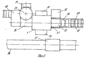
Сущность изобретения поясняется чертежом, где на фиг.1 изображен общий вид линии, реализующей способ изготовления строительных блоков прессованием;
на фиг.2 вид линии в плане;
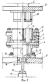
на фиг.3 общий вид пресс-формы;
на фиг.4 вид пресс-формы в плане;
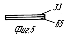
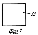
на фиг.5-10 элементы и выполнение сборно-разборного приспособления;
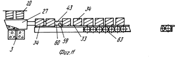
на фиг.11 взаимное расположение оборудования в крайнем правом положении каретки формовочного поста, когда одновременно на соответствующих позициях линии происходит загрузка формовочной смеси в пресс-форму, укладка перегружателем изделий на приемный лоток и перемещение толкающим механизмом предыдущего лотка на приемное устройство;
на фиг.12 вид в плане фиг.11;
на фиг. 13-14 схемы, иллюстрирующие различные этапы работы на позициях "приемное устройство" штабелирование";
на фиг.15 толкающий механизм;
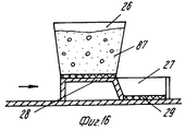
на фиг.16 18 схемы, иллюстрирующие различные моменты работы и взаимного расположения мерного питателя загрузочного устройства с расходным бункером и пресс-формой;
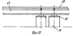
на фиг. 19 20 изображены соответственно выполнение манипуляторов типа "пневматический схват" и вид в плане;
на фиг.21 зона пониженной прочности на строительных блоках;
на фиг.22 вид сбоку механизма поперечной подачи приемных лотков;
на фиг.23 то же, вид спереди;
на фиг. 24 показано в плане положение приемного лотка в магазине механизма поперечной подачи лотков;
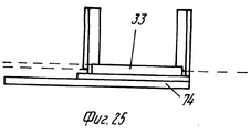
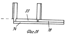
на фиг.25 26 схемы расположения приемных лотков в крайних положениях тележки механизма поперечной подачи;
на фиг.27 общий вид штабелирующего устройства;
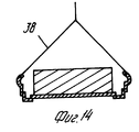
на фиг. 28 то же, вид при загрузке тарой с изделиями;
на фиг.29 вид в плане штабелирующего устройства;
на фиг. 30 изображено выполнение поворотных опор штабелирующего устройства.The invention is illustrated in the drawing, where figure 1 shows a General view of a line that implements a method of manufacturing building blocks by pressing;
figure 2 is a plan view of the line;
figure 3 General view of the mold;
figure 4 is a view of the mold in plan;
figure 5-10 elements and the implementation of collapsible devices;
Fig. 11 shows the relative position of the equipment in the extreme right position of the carriage of the molding station, when the molding mixture is loaded onto the mold at the corresponding line positions, the products are loaded onto the receiving tray by the loader and the previous tray is moved by the pushing mechanism to the receiving device;
Fig. 12 is a plan view of Fig. 11;
in FIG. 13-14 diagrams illustrating the various stages of work on the positions of the "receiving device" stacking ";
on Fig pushing mechanism;
on Fig 18 18 diagrams illustrating various aspects of the work and the relative positioning of the measured feeder boot device with a feed hopper and a mold;
in FIG. 19 to 20 respectively show the implementation of manipulators of the type "pneumatic gripper" and a view in plan;
in Fig.21 zone of reduced strength on building blocks;
Fig.22 is a side view of the transverse feed mechanism of the receiving trays;
Fig.23 is the same front view;
in FIG. 24 is a plan view of the position of the receiving tray in the magazine of the lateral tray feeding mechanism;
on Fig 26 the location of the receiving trays in the extreme positions of the cart mechanism of the lateral feed;
on Fig General view of the stacking device;
in FIG. 28 the same, view when loading containers with products;
on Fig plan view of the stacking device;
in FIG. 30 shows the implementation of the rotary supports of the stacking device.
Производство строительных блоков осуществляется по поточно-агрегатной технологии, обеспечивающей ритмичный выпуск блоков требуемого качества методом гиперпрессования полусухой формовочной массы на оборудовании линии, в состав которой входит пресс 1, имеющий гидравлический привод 2 и заявляемая пресс-форма. Пресс-форма содержит двухсекционную матрицу 3, представляющую собой замкнутую по периметру конструкцию, установленную подвижно в вертикальной плоскости и с возможностью опоры на основание 4 посредством четырех упругих элементов 5. Для этого на внешней поверхности матрицы 3 имеются кронштейны 6 в виде втулок, охватывающих направляющие штыри 7, которые с одной стороны имеют регулировочные гайки 8, с другой закреплены в основание 4, причем на направляющие штыри надеты упомянутые упругие элементы 5 пружины. Основание 4 установлено на опорную плиту в виде рамы 9 пресс-формы, жестко закрепленной болтовыми соединениям на столе 10 пресса 1. В секциях матрицы 3 расположены пустотообразователи 11, закрепленные съемно на основании 4 и проходящие через окна в нижних штампах-поддонах 12. Каждый нижний штамп 12 представляет собой силовой профилированный поддон в соответствии с заданной конфигурацией поверхности строительного блока. Нижние штампы-поддоны 12 посредством пальцев 13 соединены с траверсой 14, через которую они связаны с механизмом выпрессовки. Механизм выпрессовки выполнен в виде штанги-толкателя 15, установленного по вертикальной оси симметрии двухсекционной матрицы 3 пресс-формы 1 между траверсой 14 и обоймой 16 выталкивателя 17 пресса 1, при этом вертикальный толкатель 15 со стороны траверсы 14 снабжен гильзой 18, в которую посажен скользящей посадкой и закреплен в ней пальцем 19, а сама гильза 18 жестко прикреплена своей торцевой поверхностью к траверсе 14. С другой стороны вертикальный толкатель 15 свободно опирается на обойму 16, находясь в ее углублении трапецеидально1 формы, и выполнен с диаметром, составляющим не менее 1/3 линейного размера траверсы 14, расположенной внутри рамы 9. Над матрицей 3 пресс-формы опозитно каждой ее секции установлен соответствующий верхний штамп 20, при этом верхние штампы 20 закреплены в ползуне 21 пресса 1, связанным со штоком гидроцилиндра 2, и имеют профильную поверхность в соответствии с конфигурацией верхнего основания изделия, а также полости для прохождения пустотообразователей 11. На верхних штампах 20 закреплены также ограничители перемещения (на чертеже не показаны), контактирующие с верхними торцами матрицы 3. На боковых стенках матрицы 3 закреплены вибраторы 22. The production of building blocks is carried out according to the flow-aggregate technology, which ensures the rhythmic release of the blocks of the required quality by hyperpressing the semi-dry molding mass on the equipment of the line, which includes a press 1 having a
Заявленная линия содержит установленные последовательно на технологических позициях:
смесительный модуль, включающий бункера-накопители, дозаторы сырья для формовочной смеси (на чертеже не показаны), приводной бетоносмеситель 23 с шибером и скиповый подъемник 24;
загрузочное устройство, содержащие стол 25, расходный бункер 26, мерный питатель 27, имеющий заслонку 28, и уплотнитель 29;
формовочный пост 30, который с прессом 1 и приемным устройством 31 в виде рольганга, образуют продольное направление линии;
между прессом 1 и рольгангом 31 установлен механизм 32 поперечной подачи пустых приемных лотков 33 для готовых изделий 34 свежеотформованных строительных блоков после их выпрессовки из матрицы 3 пресс-формы. Приемные лотки 33 и поддоны-накопители 35 образуют сборно-разборное приспособление, выполненное с возможностью взаимодействия с технологическим оборудованием на технологических позициях линии. На позиции приемного устройства 31 оно служит тарой для готовых изделий 34, причем приемные лотки 33 являются промежуточным элементом, несущим изделия 34, а поддоны накопители 35 базовым. Параллельно основному ряду оборудования на рельсовых путях 36 установлено штабелирующее устройство 37 в виде контейнера для тары с готовыми изделиями 34, для перемещения которых с позиции приемного устройства 31 в зону длительного нахождения тарно-штучных изделий служит грузозахватный механизм 38, например кран-балка. Управление соответствующим оборудованием линии осуществляется с пульта 39 в полуавтоматическом режиме (электрическая схема управления на чертеже условно не показана). Для обслуживания смесителя 23 предусмотрена эстакада 40. Линия оснащена маслостанцией 41. Мерный питатель 27 загрузочного устройства представляет собой емкость в форме ящика с наклонной задней торцевой стенкой, составляющей тупой угол с плоскостью нижнего основания, при этом установленная за торцом заслонка 28 расположена на уровне верхнего основания, а уплотнитель 29 закреплен снизу и выполнен из износостойкой резины. Формовочный пост 30 выполнен в виде рамы, на которой размещены секции путей 42 для приводной каретки 43 на колесах 44. Каретка 43 связана со штоком 45 пневмоцилиндра 46. На раме формовочного поста 30 установлен расходный бункер 26 загрузочного устройства, а на каретке 43 размещены мерный питатель 27, перегружатель 47 и толкающий механизм 48. Перегружатель 47 выполнен в виде манипуляторов типа пневматических схватов, которые предназначены для захвата за боковые стенки и укладки на приемные лотки 33 строительных блоков 34 после выпрессовки их из двухсекционный матрицы 3 пресс-формы. Каждый манипулятор перегружателя 47 состоит из соединенных болтовым соединением корпуса 49 с крышкой 50. Между ними закреплена подпружиненная пружиной 51 диафрагма 52 с отверстием в середине для штока 53, который зафиксирован гайкой 54. Другой конец штока пропущен через основание каретки 43 и соединен резьбой с пятой 55, к которой прикреплен контактный элемент подушка 56. Подушка 56 представляет собой рифленую резину в форме прямоугольника по размерам боковой стенки изделия 34, при этом пята 55 с помощью болтов 57 зафиксирована относительно корпуса 49 для предотвращения ее поворота относительно штока 53. Крышка 50 манипулятора соединена с воздуховодом 58.The claimed line contains installed sequentially at technological positions:
a mixing module, including storage hoppers, raw material dispensers for the molding sand (not shown in the drawing), a
a loading device comprising a table 25, a
molding post 30, which with a press 1 and a receiving device 31 in the form of a roller table, form a longitudinal direction of the line;
between the press 1 and the roller table 31 there is a
Толкающий механизм 48 выполнен в виде собачек 59 с фиксаторами 60, которые закреплены по краям на правом торце каретки 43. Приемное устройство 31 в виде рольганга предназначено для укладки приемных лотков 33 со свежеотформованными изделиями 34 на поддоны-накопители 35 и представляют собой раму 61 с пазами 62 для роликов 63, при этом на вертикальной стенке рамы 61 закреплены четыре фиксатора 64, которые служат для фиксации положения поддона-накопителя 35. Приемный лоток 33 представляет собой площадку с трубчатой окантовкой 65 по периметру и лыжами 66 снизу площадки. Поддон-накопитель представляет собой рамку, которая снабжена уголками 67, 68, закрепленными на ее торцах, и двумя парами петель 69, расположенных на ее длинных сторонах, при этом размеры приемного лотка 33 соответствуют размерам нескольких изделий 34, в частности двух, а длина рамки поддона-накопителя 35 выбрана из условия размещения на ней нескольких, например, четырех приемных лотков 33. The pushing mechanism 48 is made in the form of
Сборно-разборное приспособление на позиции приемного устройства (рольганга 31) является тарой, загруженной отформованными изделиями 34; дном этой тара служат приемные лотки 33, опирающиеся лыжами 66 на ролики 63 рольганга 31 и расположенные в плотную друг к другу в поддоне-накопителе 35, как в направляющих, при этом, в свою очередь, поддон-накопитель 35 рамкой уложен на раму 61 рольганга 31 и с помощью петель 69, как единое целое с приемными лотками 33, может быть перемещен грузозахватным механизмом 38 на позицию штабелирующего устройства 37. Механизм 32 поперечной подачи пустых приемных лотков 33 в зону действия перегружателя 47 имеет раму 70, на которой установлен механизм 71, а также закреплен пневмоцилиндр 72 и пути 73 (уголок) для тележки 74 на колесах 75, которая посредством кронштейна 76 соединена со штоком 77 пневмоцилиндра 72. Магазин 71 выполнен в виде стоек, между которыми размещены приемные лотки 33. В стойках со стороны подачи лотков выполнена прорезь, а на тележке имеется площадка 78, образующая ступеньку. Collapsible device at the position of the receiving device (roller table 31) is a container loaded with molded
Оборудование линии установлено с возможностью совмещения по времени нескольких операций. Так, в крайнем левом положении каретки 43 формовочного поста 30 мерный питатель 27 установлен под расходным бункером 26, перегружатель 47 находится над пресс-формой. В крайнем правом положении каретки 43 формовочного поста 30, мерный питатель расположен над пресс-формой, перегружатель 47 в зоне действия 32 поперечной подачи приемных лотков 33, а толщиной механизм 48, закрепленный на правом торце каретки 43, контактирует с одним из лотков 33. Штабелирующее устройство 37 выполнено в виде контейнера, представляющего собой многоярусную каркасную сварную конструкцию, образованную стойками 79 из уголка коробчатой формы. Стойки 79 опираются на пятаки 80, служащие для установки контейнера на контейнер. В верхней своей части стойки 79 имеют петли 81 для взаимодействия с грузоподъемным механизмом 38, а также снабжены поворотными опорами 82, 83, каждая из которых выполнена из уголка, прикрепленного к планке 84. Планка 84 посредством оси 85 жестко связана со стойкой 79 контейнера и установлена с возможностью поворота вокруг оси на 180o и фиксации фиксатором 86. Позицией 87 на чертеже обозначена формовочная масса, которая может находиться в расходном бункере 26, мерном питателе 27 и матрице 3 пресс-формы.The line equipment is installed with the possibility of combining several operations in time. So, in the extreme left position of the
Пример. В линии использован гидравлический пресс 1 модели ПК 12.6.36.09 Оренбургского завода "Гидропресс", имеющий следующие характеристики:
номинальное усилие 4000 кН
ход ползуна 21 800 мм
номинальное усилие выталкивателя 7 500 кН
наибольшее расстояние между столом 12 и ползуном 21 1400 мм
мощность 18 кВт
Пресс ПК 2.6.36.09, предназначенный для формирования изделий из слоистых пластиков, получил широкое применение в области производства строительных изделий на цементном вяжущем. Выбор пресса связан также с расстоянием между его столом 10 и ползуном 21, достаточным для установления по вертикальной оси пресс-формы, верхних штампов 20 и мерного питателя 27. Емкость мерного питателя 27 сварена из листа, уплотнитель 28 выполнен из износостойкой резины, а верхнее основание за счет наклона заднего торца питателя длиннее нижнего основания питателя на ≈150 мм, так что в крайнем правом положении каретки 43 питатель 27 выходит вперед за границу матрицы 3 ≈100 мм, обеспечивая при одном и том же ходе штока 45 цилиндра 46, равном 1050 мм, и при том же объеме питателя 27 необходимое заполнение обеих секций матрицы 3. Ход штока 45 каретки 43 формовочного поста 30 выбран 1050 мм, что является достаточным для обеспечения взаимодействия оборудования на соответствующих технологических позициях линии. В состав линии входит бетоносмеситель 23 марки СБ-80, оснащенный скипом 24. Бетоносмеситель имеет следующие характеристики:
вместимость чаши 250 л
объем готового замеса 165 л
время перемешивания 45 50 с
Подушка 56 с пятой 55 в манипуляторах (перегружатель 47) соединены клеем, например "Момент" и имеют не круглую, а прямоугольную форму. При размерах изделия 34 (200 мм x 150 мм) пята с подушкой может иметь размер (190 мм x 140 мм). Это обеспечивает захват без скалывания граней или разрушения изделия. Пустотность блоков составляет ≈50% Рама формовочного поста 30 представляет собой сваренную из швеллера N 10 конструкцию. Роль путей также выполняет швеллер N 10. Расходный бункер 26 представляет собой сваренный из листа б 3 мм короб и предназначен для направления формовочной массы 87 из смесителя 23 в мерный питатель 27. Приемные лотки 33 выполнены из металлического листа б 3 мм, по периметру обрамленного для жесткости кругляком Ф 8 мм (поз. 65). Рама поддона-накопителя 35 выполнена из уголка L 50, а со стороны одного из торцов уголка L 40 для захода приемного лотка 33 в раму, при этом, в частности на лотке 33, находятся два изделия 34, на поддоне-накопителе 8 изделий (четыре лотка), в штабелирующем устройстве 37 - 96 изделий (12 поддонов-накопителей). Зазор между обоймой 16 выталкивателя 17 пресса 1 и вертикальным выталкивателем 15 достаточно иметь в пределах 5 мм.Example. The line uses a hydraulic press of model 1 PC 12.6.36.09 of the Orenburg Hydropress plant, which has the following characteristics:
rated force 4000 kN
rated
the greatest distance between the table 12 and the
Press PK 2.6.36.09, designed for the formation of products from laminated plastics, has been widely used in the production of building products on cement binder. The choice of the press is also associated with the distance between its table 10 and the
bowl capacity 250 l
volume of the finished batch 165 l
mixing time 45 50 s
Линия работает следующим образом. The line works as follows.
После изготовления формовочной массы 87 путем дозирования каждой из ее составляющих, загружают ее скип 24 смесительного модуля и включают его привод. Происходит перемещение формовочной массы 87 в бетоносмеситель 23, после чего привод скипа 24 отключают, а привод бетоносмесителя включают на 4 6 с. Далее, при открытии шибера смесителя 23 формовочная масса поступает в расходный бункер 26 загрузочного устройства. After manufacturing the
Одновременно, магазин 71 механизма 32 поперечной подачи заполняют пустыми приемными лотками 33, а на рольганг 31 с помощью грузоподъемного механизма 38 подают поддон-накопитель 35, рамку которого укладывают на раму 61 рольганга 31. At the same time, the magazine 71 of the
В исходном состоянии приводная каретка 43 формовочного поста 30 находится в крайнем левом положении, при котором заслонка 28 смещена относительно горловины расходного бункера 26 (см. фиг. 17), а под ней расположен мерный питатель 27, в результате чего происходит заполнение его формовочной смесью 87. Далее, включением пневмоцилиндра 46 приводят в движение каретку 43. При этом формовочная масса 87, находясь в закрепленном на каретке мерном питателе 27, одновременно перемещается по столу 25 слева направо и, достигнув начала зоны пресс-формы, где заканчивается стол 25, начинает заполнять первую по ходу каретки 43 секцию матрицы 3, затем вторую. При полном выдвижении штока 45 передняя стенка мерного питателя 27 выходит за границу второй по ходу секции матрицы 3, обеспечивая таким образом заполнение обеих секций в заданном объеме (см. фиг.16, 18), что обеспечивается конструкцией мерного питателя 27. Во время заполнения пресс-формы формовочной массой 87 работают 2 3 с вибраторы 22, обеспечивая более равномерное заполнение секции матрицы. После этого вибраторы 22 отключают, а каретка 43 при реверсе штока 45 возвращается в крайнее левое положение (в крайних положениях каретка 43 взаимодействует с пружинными амортизаторами, оказывающими тормозящее действие на чертеже не показаны). In the initial state, the
Одновременно, приводят в работу гидроцилиндр 2 пресса 1, происходит двустороннее прессование формовочной массы 87, находящейся в секциях матрицы 3, при движении вниз ползуна 21 с верхними штампами 20. При этом матрица 3, сжимая пружины 5, опускается до упора в основание 4, которое через опорную плиту 9 упирается в стол 10 пресса 1. Смещение ее относительно неподвижных нижних штампов 12 соответствует "подему" их, то есть внедрению снизу в формовочную массу 87 с усилием, равным в каждый момент усилию со стороны верхних штампов 20. При достижении заданного давления не менее 30 МПа в гидросистеме (что определяется по манометру на чертеже не показан) от датчика давления системы управления подается команда на отключение гидроцилиндра 2 пресса 1. Один цикл прессования включает время нарастания давления до 30 МПа, что в сумме с временем выдержки формовочной массы после отключения гидроцилиндра 2 из-за инерционности гидросистемы составляет до 5 с. В течение этого времени происходит формование пустот с помощью съемных пустотообразователей 11. В результате отключения гидроцилиндра 2 ползун 21 с верхними штампами 20 возвращается в свое исходное верхнее положение до остановки в нем. После этого автоматически осуществляется включение механизма выпрессовки изделия 34 (см. фиг. 3). Для этого включают привод выталкивателя 17, который, перемещаясь вверх, воздействует на вертикальный толкатель 15 и через него на траверсу 14 с закрепленными в ней пальцами 13 нижних штампов-поддонов 12 с изделиями 34. Свежеотформованные (готовые) изделия 34 выходят из матрицы 3, после чего осуществляется захват их за боковые стенки с помощью манипуляторов перегружателя 47 (см. фиг.19-21). Манипуляторы срабатывают при поступлении сжатого воздуха по воздухопроводу 58 при открытии клапана по команде с пульта 39 управления. Диафрагма 52 смещается, преодолевая усилие пружины 51 и приводит в движение шток 53. Болты 57 предотвращают поворот пяты 55 вокруг штока 53. В этот момент происходит захват за боковые стенки лежащих на штампах-поддонах 12 изделий 34 подушками 56. Одновременно отключается механизм выпрессовки. В результате нижние штампы 12 вместе с траверсой 14 и вертикальным толкателем 15 опускаются в нижнее положение под собственным весом, при этом толкатель 15 нижним концом все время касается обоймы 16. В момент, когда нижние штампы-поддоны 12 опускаются до основания 4 (см. фиг.3), вертикальный толкатель 15 останавливается, а выталкиватель 17 пресса 1 еще продолжает опускаться в свое исходное положение. После этого приводится в движение каретка 43 формовочного поста 30, которая находилась в течение операций прессования, выпрессовки и захвата готового изделия 34 в крайнем левом положении, в котором ранее произошла засыпка мерного питателя 27 формовочной смесью 87. At the same time, the
Теперь за время одного прямого хода каретки 43 выполняются две операции: происходит загрузка формовочной массы из мерного питателя 27 в матрицу 3 при достижении кареткой 43 крайнего правого положения и вынос готового свежеотформованного изделия 34 манипуляторами (перегружателем 47) в зону действия механизма 32 поперечной подачи приемных лотков 33. По достижении кареткой 43 крайнего правого положения приводится в действие пневмоцилиндр 72 тележки 74, с помощью которой пустые приемные лотки 33 поступают под изделие 34, удерживаемые манипуляторами (перегружателем 47). Зазор прохода приемного лотка под изделием не превышает 2 5 мм. Подача приемных лотков 33 поясняется чертежом (см. фиг.22-26). Now, during one direct stroke of the
Нахождение площадки 78 в зоне, ограниченной стойками 79, является исходным (см. фиг.25). Далее, при перемещении тележки 74 назад (от продольного направления линии), происходит самовыгрузка приемного лотка 33 из магазина 71 на основание тележки 74 (см. фиг.26), при этом в прорезь на стойках 79 выходит только нижний лоток, а на его место в этот момент под собственным весом ложится следующий. В этот момент ходом тележки 74 вперед, в другое крайнее положение, приемный лоток перемещается в зону действия манипуляторов 47, удерживающих изделие 34, а площадка 78 входит в зону между стойками 79, не допуская самовыгрузку следующего лотка из магазина 71. Далее, прямой и обратный ходы тележки 74 повторяются. При установлении изделий 34 над лотком 33 отключают перегружатель 47, перекрывая подачу сжатого воздуха. Пружина 51 возвращает диафрагму 52 в исходное положение, в результате готовое изделие 34 переходит на приемный лоток 33. The location of the
Далее происходит повторение операций после достижения кареткой 43 при обратном ходе штока крайнего левого положения:
на позиции прессования уплотнение формовочной массы 87 с образователем изделия 34, выпрессовка его из матрицы 3 и возврат выталкивателя 17 пресса 1 и элементов пресс-формы в исходные положения;
на позиции перегрузки захват изделия 34 манипуляторами (перегружателем 47).Then there is a repetition of operations after reaching the
at the pressing position, sealing the
at the overload position, the capture of the
Далее снова прямой ход каретки 43. Теперь при ее перемещении в крайнее правое положение выполняют три операции:
загрузка матрицы 3 формовочной смесью 87;
вынос готового изделия 34 из зоны прессования перегружателем 47;
перемещение посредством толкающего механизма 48 (собачек 59 с фиксаторами 60) приемного лотка 33 с двумя готовыми изделиями 34 на ролики 63 рольганга 31.Then again the forward stroke of the
loading the
removal of the
moving through the pushing mechanism 48 (
На фиг. 11 12 показано взаимное положение верхних штампов 20, мерного питателя 27, пресс-формы, рольганга в крайнем правом положении каретки 43, когда мерный питатель находится над пресс-формой, манипуляторы 47 захватили изделие 34 и вынесли его из зоны пресса, а собачки 59 проталкивают, то есть перемещают линейно в горизонтальной плоскости приемный лотки 33 по рольгангу 31. Базовый элемент (поддон-накопитель 35) выполняет в этом случае роль направляющих для приемных лотков 33. При последующих движениях процесс повторяется. Приемный лоток 33 проталкивает предыдущий до заполнения поддона-накопителя 35. In FIG. 11 12 shows the relative position of the upper dies 20, the
На фиг.13 изображена рамка поддона-накопителя 35 с приемными лотками 33, на фиг.14 момент снятия ее с рольганга 31. В этом случае приемные лотки 33 и рамка становятся одним целым, выполняя роль тары. In Fig.13 shows the frame of the
При заполнении поддона-накопителя 35, находящегося на рольганге 31, приемными лотками 33, которые уложены встык, поддон-накопитель 35 снимается за петли 69 грузоподъемным механизмом 38 и перемещается им в контейнер 37 (штабелирующее устройство), для чего две нижние опоры 82 должны быть задвинуты (повернуты вовнутрь), а остальные верхние 83 откинуты на внешнюю от стоек 79 сторону контейнера 37. По мере заполнения его поддонами 35, опоры 83 переводят вовнутрь (см. фиг.29-30). Приведение в работу смесителя 23 и скипа 24 может осуществляться как с пульта 39 управления, так и с эстакады 40, предназначенной для обслуживания смесителя. Подготовку формовочной смеси 87 можно осуществлять параллельно с процессом прессования, выпрессовки и т. д. When filling the pallet-
Для обслуживания технической линии предусмотрено 3 человека. Производительность линии 100 блоков/час. Установочная мощность 25 КВЧ. Производительная площадь (8x8)м2.3 people are provided for servicing the technical line. Productivity of the line is 100 blocks / hour. Installed capacity of 25 UHF. Production area (8x8) m 2 .
Заявленный способ изготовления строительных блоков с помощью описанной линии осуществляется следующим образом. Используя оборудование смесительного модуля, производят подготовку строительной смеси в виде цементно-минеральной композиции, которая включает гидравлическое вяжущее, минеральные заполнители и воду. В качестве вяжущего используется портландцемент или его разновидности согласно требованниям ГОСТ 10178, марка цемента не ниже 400. В качестве заполнителя применяется кварцевый песок или технологические отходы в виде граншлака. Дополнительно в состав вводят пластификатор в виде шлам-отхода водоочистки ТЭЦ. Требования к физико-механическим свойствам следующие. The claimed method of manufacturing building blocks using the described line is as follows. Using the equipment of the mixing module, the construction mixture is prepared in the form of a cement-mineral composition, which includes a hydraulic binder, mineral aggregates and water. Portland cement or its varieties are used as a binder according to the requirements of GOST 10178, the cement grade is not lower than 400. Quartz sand or technological waste in the form of granulated slag is used as a filler. In addition, a plasticizer is introduced into the composition in the form of sludge from the waste water treatment of a thermal power plant. The requirements for physical and mechanical properties are as follows.
Состав кварцевого песка:
модуль крупности 1,8 1,5;
насыпная плотность сухого песка 1,345 кг/л;
содержание глинистых примесей 3,4%
Физические свойства шлам-отхода:
содержание глинистых примесей 3,5 4,5%
содержание органических примесей не превышает допустимого по ГОСТ 8735;
насыпная плотность 0,76 кг/л.The composition of quartz sand:
fineness modulus 1.8 1.5;
bulk density of dry sand 1,345 kg / l;
clay impurities content 3.4%
Physical properties of sludge waste:
clay impurities content 3.5 4.5%
the content of organic impurities does not exceed the permissible according to GOST 8735;
bulk density of 0.76 kg / l.
Подбор состава формовочной массы для изготовления блоков осуществляют с учетом заданной прочности. The composition of the molding material for the manufacture of blocks is carried out taking into account the given strength.
Основные типы блоков:
СБП пустотные со сквозными пустотами (-50%) для кладки стен и перегородок надземных частей зданий;
ФБС сплошные для кладки фундаментов.The main types of blocks:
SBP hollow with through voids (-50%) for masonry walls and partitions of aboveground parts of buildings;
FBS continuous for laying foundations.
Используемый состав для изготовления блоков СБП (в мас. ):
цемент М400 12
граншлак 73
шлам-отход водоочистки ТЭЦ 15
100%
Влажность формовочной массы должна быть 7-8%
Для блоков ФБС (в мас.):
цемент М400 15
песок кварцевый 65
шлам-отход водоочистки ТЭЦ 20
100%
Рабочая влажность формовочной массы должна быть 7 8% При меньшей влажности в смесь добавляют расчетное количество воды. Отдозированные компоненты перемешиваются в бетоносмесителе 23 принудительного действия с образованием полусухой формовочной массы 87. Перемешивание осуществляется в следующем порядке: песок, шлам-отход, цемент, вода или граншлак, шлам-отход, цемент, вода в течение времени, необходимого для получения формовочной массы однородной консистенции (≈40 60 с). При смешивании компонентов в них может быть введен минеральной щелочестойкий пигмент 1 10% предварительно перемешанный с вяжущим (расход в к массу сухой смеси). На позиции загрузочного устройства приготовленная формовочная масса 87 поступает в расходный бункер 26, и далее в мерный питатель 27. Заполнение последнего осуществляют с превышением по объему на 2-3% это необходимо для получения блока заданных размеров и плотности. Отношение высоты готового блока к высоте рыхлой засыпки формовочной смеси должно составлять 0,587 0,589 при давлении 30 МПа. Это условие реализуется путем предварительного расчета размеров матрицы 3 пресс-формы и мерного питателя 27. Во время заполнения матрицы 3 формовочной массой 87 на последнюю воздействуют виброимпульсами посредством пружин 5 матрицы 3. Далее, в течение одного цикла (одностадийно) осуществляют уплотнение формовочной массы 87. Прессование ведут с использованием гипердавления, не менее 30 МПа при двухстороннем сжатии формовочной массы, которое осуществляют путем создания встречно направленных равных усилий: со стороны проводных верхних штампов 20 при перемещении их сверху вниз и внедрения в формовочную массу 87 нижних неподвижных штампов 12. Внедрение происходит вследствие того, что сцепленная с формовочной массой силами трения о боковые стенки матрица, смещается вниз относительно нижних штампов, создавая эффект их "подъема" без наличия привода, причем происходит синхронное и равное с обеих сторон уплотнение при нарастающем до заданного значения давлении (30 МПа и более).Used composition for the manufacture of SBP blocks (in wt.):
sludge-waste
one hundred%
The moisture content of the molding material should be 7-8%
For FBS blocks (in wt.):
sludge-waste
one hundred%
The working humidity of the molding material should be 7-8%. At lower humidity, the calculated amount of water is added to the mixture. The dosed components are mixed in a forced-action
Формование сквозных пустот в блоках 34 ведут в течение цикла прессования при неподвижных и выдвинутых на всю длину пустотообразователях 11 путем постепенного утопления их в окнах верхних штампов 20 в процессе перемещения этих штампов сверху вниз и уплотнении формовочной массы 37. Один цикл прессования составляет до 5 с, включая время нарастания давления до 30 МПа и выдержки при этом давлении (≈250 кг/см2). Извлечение отформованных блоков 34 из секций матрицы 3 ведут при подъеме нижних штампов-поддонов 12 под воздействием на них механизма выпрессовки. Структурная прочность свежеотформованного блока составляет не менее 0,5 МПа, что является достаточным для съема, перегрузки и транспортировки блоков согласно технологическому маршруту до завершающей операции тепловой обработки (сушки). Технологический маршрут включает съем отформованных блоков 34 с нижних штампов-поддонов 12 после выпрессовки, перегрузку их на промежуточный элемент приемные лотки 33 сборно-разборного приспособления, на которых блоки 34 поступают на базовый элемент этого приспособления поддон-накопитель 35 и далее, на нем на позиции штабелирования и тепловой обработки. Таким образом, транспортировка свежеотформованных блоков осуществляется в таре причем с использованием простых линейных перемещений в горизонтальной и вертикальной плоскостях параллельно самим себе. Завершающая операция сушка - предназначена для ускорения твердения. Тепловой режим в часах (2 + 6 + 2), где 2 часа подъем температуры, 6 часов изотермический прогрев при to 80oC, 2 часа охлаждение до 40oC. В случае естественного твердения, изделия хранятся в штабеле не менее трех суток, затем перемещаются на склад готовой продукции.The formation of through voids in the
Заявленный способ изготовления строительных блоков прессованием обеспечивает характеристики и параметры, приведенные в таблице. The claimed method of manufacturing building blocks by pressing provides the characteristics and parameters shown in the table.
Строительные блоки, изготавливаемые по заявленной технологии и на заявленном оборудовании, обладают заданными параметрами, обеспечивающими надежность в эксплуатации, при этом они экологически чисты и имеют эстетический вид. Building blocks manufactured according to the claimed technology and the declared equipment have the specified parameters that ensure reliability in operation, while they are environmentally friendly and have an aesthetic appearance.
Claims (4)
Priority Applications (1)
| Application Number | Priority Date | Filing Date | Title |
|---|---|---|---|
| RU95106931A RU2087307C1 (en) | 1995-05-03 | 1995-05-03 | Method of production of building blocks by moulding, mould and line for realization of method |
Applications Claiming Priority (1)
| Application Number | Priority Date | Filing Date | Title |
|---|---|---|---|
| RU95106931A RU2087307C1 (en) | 1995-05-03 | 1995-05-03 | Method of production of building blocks by moulding, mould and line for realization of method |
Publications (2)
| Publication Number | Publication Date |
|---|---|
| RU95106931A RU95106931A (en) | 1997-01-27 |
| RU2087307C1 true RU2087307C1 (en) | 1997-08-20 |
Family
ID=20167292
Family Applications (1)
| Application Number | Title | Priority Date | Filing Date |
|---|---|---|---|
| RU95106931A RU2087307C1 (en) | 1995-05-03 | 1995-05-03 | Method of production of building blocks by moulding, mould and line for realization of method |
Country Status (1)
| Country | Link |
|---|---|
| RU (1) | RU2087307C1 (en) |
Cited By (9)
| Publication number | Priority date | Publication date | Assignee | Title |
|---|---|---|---|---|
| WO2014089663A1 (en) | 2012-12-14 | 2014-06-19 | Kondratiuk Oleksii Mikhailovich | Method of manufacturing building blocks and a mold for manufacturing row building blocks or corner building blocks |
| RU2534208C2 (en) * | 2012-12-11 | 2014-11-27 | Валерий Александрович Кливзуник | Production of heat isolation blocks by counter compaction for erection of guarding structures and buildings |
| RU2572630C2 (en) * | 2011-06-09 | 2016-01-20 | Рекерс Фервальтунгс Гмбх Унд Ко. Кг | Machine for production of stones with linearly directed bearing element |
| RU2572874C2 (en) * | 2011-06-09 | 2016-01-20 | Рекерс Фервальтунгс Гмбх Унд Ко. Кг | Device for production of concrete stones and production of at least two-colour concrete stones |
| RU2604889C2 (en) * | 2015-06-22 | 2016-12-20 | Вадим Владимирович Батуков | Production line for production of wall plates from gypsum or gypsum concrete |
| WO2020084581A1 (en) * | 2018-10-25 | 2020-04-30 | Kadam Sunil Dhondibhau | System and method for generating customized bricks |
| RU2730093C1 (en) * | 2015-11-16 | 2020-08-17 | Систем Керамикс С.п.А. | Forming element for ceramic articles |
| RU2761452C2 (en) * | 2016-03-31 | 2021-12-08 | Лангенштайн И Шеманн Гмбх | Device and method for manufacturing pressed brick workpieces |
| RU2773898C1 (en) * | 2021-04-29 | 2022-06-14 | Компания Домидо Лимитед | Method for manufacturing a building block |
-
1995
- 1995-05-03 RU RU95106931A patent/RU2087307C1/en active
Non-Patent Citations (1)
| Title |
|---|
| Патент СССР N 1839653, кл. B 28 B 3/02, 1993. Патент РФ N 2001757, кл. B 28 B 3/00, 1994. Авторское свидетельство СССР N 1472266, кл. B 28 B 3/00, 1989. * |
Cited By (11)
| Publication number | Priority date | Publication date | Assignee | Title |
|---|---|---|---|---|
| RU2572630C2 (en) * | 2011-06-09 | 2016-01-20 | Рекерс Фервальтунгс Гмбх Унд Ко. Кг | Machine for production of stones with linearly directed bearing element |
| RU2572874C2 (en) * | 2011-06-09 | 2016-01-20 | Рекерс Фервальтунгс Гмбх Унд Ко. Кг | Device for production of concrete stones and production of at least two-colour concrete stones |
| RU2534208C2 (en) * | 2012-12-11 | 2014-11-27 | Валерий Александрович Кливзуник | Production of heat isolation blocks by counter compaction for erection of guarding structures and buildings |
| WO2014089663A1 (en) | 2012-12-14 | 2014-06-19 | Kondratiuk Oleksii Mikhailovich | Method of manufacturing building blocks and a mold for manufacturing row building blocks or corner building blocks |
| DE212012000289U1 (en) | 2012-12-14 | 2015-08-18 | Technopark Limited Liability Company | Form for the production of series modules (variants) or corner modules (variants) |
| RU2604889C2 (en) * | 2015-06-22 | 2016-12-20 | Вадим Владимирович Батуков | Production line for production of wall plates from gypsum or gypsum concrete |
| RU2730093C1 (en) * | 2015-11-16 | 2020-08-17 | Систем Керамикс С.п.А. | Forming element for ceramic articles |
| US11020875B2 (en) | 2015-11-16 | 2021-06-01 | System Ceramics S.P.A. | Forming element for ceramic articles |
| RU2761452C2 (en) * | 2016-03-31 | 2021-12-08 | Лангенштайн И Шеманн Гмбх | Device and method for manufacturing pressed brick workpieces |
| WO2020084581A1 (en) * | 2018-10-25 | 2020-04-30 | Kadam Sunil Dhondibhau | System and method for generating customized bricks |
| RU2773898C1 (en) * | 2021-04-29 | 2022-06-14 | Компания Домидо Лимитед | Method for manufacturing a building block |
Also Published As
| Publication number | Publication date |
|---|---|
| RU95106931A (en) | 1997-01-27 |
Similar Documents
| Publication | Publication Date | Title |
|---|---|---|
| US4869660A (en) | Apparatus for fabrication of concrete brick | |
| US3904723A (en) | Concrete product manufacturing system and method | |
| CN1657251A (en) | Automatic shaping method and equipment for load-bearing hollow brick | |
| UA82445C2 (en) | Processing line for producing multilayer building blocks with decorative surface | |
| WO2007042479A1 (en) | Plant for producing slabs of conglomerate stone material | |
| RU2087307C1 (en) | Method of production of building blocks by moulding, mould and line for realization of method | |
| CN103231432B (en) | Full-automatic seismic masonry forming machine and its implementation | |
| US2624928A (en) | Press for molding concrete building elements | |
| KR20040102484A (en) | A system for automatically manufacturing concrete products | |
| FI128156B (en) | Method and system for recycling concrete mass in a slipform casting process, and casting machine | |
| CN211250550U (en) | Building block forming device | |
| US4421466A (en) | Apparatus for molding concrete articles and the like | |
| US4098563A (en) | Concrete product manufacturing system | |
| CN203210490U (en) | Full-automatic novel anti-seismic brickwork forming machine | |
| KR101090137B1 (en) | Automated facilities for producing utility pole underbracing | |
| US20030082258A1 (en) | Apparatus for molding brick and brick paver | |
| WO2006006888A1 (en) | Method for producing laminated building blocks provided with a decorative surface | |
| RU2533475C1 (en) | High-speed method of manufacture of building products with high void ratio by volumetric vertical moulding from heterogeneous mixes, building product with high void ratio, process line for manufacture of building products with high void ratio by volumetric vertical moulding from heterogeneous mixes | |
| US4036575A (en) | Concrete product manufacturing system | |
| US9352487B2 (en) | Block machine and method for vertically adjusting a block machine | |
| US2965948A (en) | Apparatus for producing pre-cast concrete members | |
| CN106738193B (en) | Concrete formwork block manufacturing machine | |
| RU2534208C2 (en) | Production of heat isolation blocks by counter compaction for erection of guarding structures and buildings | |
| JP2521465B2 (en) | Concrete product molding equipment | |
| RU2037400C1 (en) | Apparatus for molding products from construction materials |