RU2013556C1 - Broken rock loading device - Google Patents
Broken rock loading device Download PDFInfo
- Publication number
- RU2013556C1 RU2013556C1 SU914894260A SU4894260A RU2013556C1 RU 2013556 C1 RU2013556 C1 RU 2013556C1 SU 914894260 A SU914894260 A SU 914894260A SU 4894260 A SU4894260 A SU 4894260A RU 2013556 C1 RU2013556 C1 RU 2013556C1
- Authority
- RU
- Russia
- Prior art keywords
- conveyor
- loading
- plate
- beams
- support
- Prior art date
Links
Images

Classifications
-
- B—PERFORMING OPERATIONS; TRANSPORTING
- B65—CONVEYING; PACKING; STORING; HANDLING THIN OR FILAMENTARY MATERIAL
- B65G—TRANSPORT OR STORAGE DEVICES, e.g. CONVEYORS FOR LOADING OR TIPPING, SHOP CONVEYOR SYSTEMS OR PNEUMATIC TUBE CONVEYORS
- B65G65/00—Loading or unloading
- B65G65/02—Loading or unloading machines comprising essentially a conveyor for moving the loads associated with a device for picking-up the loads
- B65G65/08—Loading or unloading machines comprising essentially a conveyor for moving the loads associated with a device for picking-up the loads with reciprocating pick-up conveyors
- B65G65/10—Raking or scraping devices
- B65G65/12—Raking or scraping devices operations at positions off-set from the conveyor centreline
Abstract
Description
Изобретение относится к погрузочному устройству для загрузки отбитой руды на головной конец транспортера, в частности, с установленной перед головным концом транспортера погрузочной рампой, предназначенной для горнодобывающей промышленности проходческой машиной, выше погрузочной рампы сбоку от головного конца транспортера выполнены треугольные в поперечном сечении погрузочные балки, которые имеют на обращенной к транспортеру стороне одну круто поднимающуюся, а на другой стороне полого поднимающуюся боковые поверхности и которые выполняют возвратно-поступательное движение в направлении к транспортеру и от него, причем каждая погрузочная балка на обращенной от транспортера стороне на конце траектории движения в обратном направлении выполнена с одной аналогичной в поперечном сечении опорной балкой или одной опорной стенкой. The invention relates to a loading device for loading broken ore onto the head end of the conveyor, in particular with a loading ramp installed in front of the head end of the conveyor designed for the mining industry, loading beams triangular in cross section made above the loading ramp to the side of the conveyor end have on the side facing the conveyor one steeply rising, and on the other side of the hollow rising side surfaces and which in They perform reciprocating movement towards and from the conveyor, with each loading beam on the side facing away from the conveyor at the end of the reverse movement path having one supporting beam, similar in cross section, or one supporting wall.
Известно погрузочное устройство (заявка ФРГ N 3546192), в котором расположенные сбоку рядом с головным концом транспортера погрузочные балка перемещаются с выполнением качательного движения вокруг своего обращенного от переднего края погрузочной рампы конца в направлении к головной части транспортера и от него, а именно в области поверхности погрузочной рампы, в то время как неподвижные опорные балки укреплены на поверхности погрузочной рампы. Known loading device (application Germany N 3546192), in which the loading beams located on the side next to the head end of the conveyor move with a swinging movement around its end facing the front of the loading ramp towards and from the conveyor head, namely in the surface area loading ramp, while the fixed support beams are mounted on the surface of the loading ramp.
В известных погрузочных устройствах, которые содержат сбоку от головной части транспортера более одной погрузочной балки, происходит усложнение привода в движение погрузочных балок. При использовании этих устройств, а также погрузочных устройств с одной погрузочной балкой, расположенной сбоку с возможностью поворота, возникают дополнительные трудности, поскольку погрузочные балки укреплены с возможностью поворота лишь на одном конце на цапфе и должны направляться относительно вплотную к поверхности рампы, в результате чего может произойти заклинивание загружаемого материала, что ведет к сильной нагрузке на повороте на шарнирное соединение и интенсивному износу. In known loading devices, which comprise on the side of the conveyor head more than one loading beam, the driving of the loading beams is complicated. When using these devices, as well as loading devices with one loading beam, which is rotatable laterally, additional difficulties arise, since the loading beams are mounted with the possibility of rotation only at one end on the axle and must be guided relatively close to the ramp surface, as a result of which seizure of the feed material occurs, which leads to a strong bend load on the swivel joint and intense wear.
Целью изобретения является создание погрузочного устройства, которое отличается прочной и более простой конструкцией и в меньшей степени подвержено отказам. The aim of the invention is the creation of a loading device, which has a strong and simpler design and is less prone to failure.
Для этого погрузочные балки стационарно укреплены на транспортировочной плите, которая может выполнять возвратно-поступательные движения на погрузочной рампе в направлении к транспортеру и от него, а опорные балки простираются в сторону от транспортировочной плиты и опираются отдельно от нее. To do this, the loading beams are stationary mounted on the transport plate, which can perform reciprocating movements on the loading ramp in the direction to and from the conveyor, and the support beams extend to the side of the transport plate and rest separately from it.
За счет такого конструктивного выполнения все подвижные погрузочные балки могут перемещаться с помощью одного приводного агрегата, кроме того, отсутствуют шарнирные соединения, которые нагружают в результате заклинивания загружаемого материала, так как обеспечивается возможность безупречного направления транспортировочной плиты, силы, обусловленные заклиниванием загружаемого материала, не оказывают отрицательного влияния на привод, а приводные средства располагаются под транспортировочной плитой, где они защищены от соприкосновения с транспортируемым материалом. Due to such a structural embodiment, all movable loading beams can be moved using a single drive unit, in addition, there are no swivel joints that load as a result of jamming of the loaded material, since it is possible to flawlessly direct the transport plate, the forces due to jamming of the loaded material do not exert negative impact on the drive, and the drive means are located under the transport plate, where they are protected from contact Nia with the transported material.
Известно погрузочное устройство (заявка ФРГ N 3304908), в котором сбоку от головного конца транспортера предусмотрены погрузочные балки с треугольным поперечным сечением, перемещающиеся с возвратно-поступательным движением поперечно их продольному направлению прямолинейно к концу головной части и от него. Однако они укреплены лишь одним концом на выполняющем возвратно-поступательные движения шибере и по этой причине при заклинивании загружаемого материала подвергаются воздействию значительных изгибающих нагрузок. Кроме того, приводные средства расположены в области загружаемого материала, в результате чего они подвержены значительному загрязнению и износу. В предлагаемом погрузочном устройстве опорные балки укреплены на своих выступающих за пределы транспортировочной плиты концах по обеим сторонам указанной плиты на погрузочной рампе, в результате чего также и в этом случае не возникают эксплуатационные трудности. A loading device is known (FRG application N 3304908), in which loading beams with a triangular cross section are provided on the side of the conveyor head, moving with reciprocating motion transversely to their longitudinal direction straight to and from the end of the head part. However, they are fixed with only one end on the sliding gate, and for this reason, when jamming the feed material, they are exposed to significant bending loads. In addition, the drive means are located in the area of the feed material, as a result of which they are subject to significant contamination and wear. In the proposed loading device, the support beams are fixed at their ends protruding beyond the transport plate on both sides of the specified plate on the loading ramp, as a result of which also in this case there are no operational difficulties.
Следующее преимущество этого конструктивного исполнения заключается в том, что стационарно соединенные с погрузочной рампой опорные балки несут часть груза, находящегося на погрузочной рампе, и тем самым разгружают подвижные части и, следовательно, их привод. A further advantage of this design is that the support beams fixed to the loading ramp carry part of the load on the loading ramp and thereby unload the moving parts and, therefore, their drive.
Эффект транспортировки может быть также улучшен за счет того, что опорные балки соединены с погрузочной рампой не стационарно, а оснащены приводом, с помощью которого они поворачиваются. The transport effect can also be improved due to the fact that the support beams are not connected to the loading ramp stationary, but are equipped with a drive by which they are rotated.
Под транспортировочной плитой на погрузочной рампе предусмотрена закрывающая плита, которая закрывает расположенное ниже транспортировочной плиты пространство настолько, насколько оно деблокируется при возвратно-поступательном движении транспортировочной плиты. С помощью этой закрывающей плиты загружаемый материал, который поступает от расположенных перед транспортером погрузочных балок, сдвигается на транспортер. При этом предпочтительным является момент, когда эта погрузочная балка своей крутой боковой поверхностью с обращенной к транспортеру кромкой контактирует с транспортировочной плитой. Загружаемый материал, который поступает в процессе движения транспортировочной плиты вперед на внешнюю полосу закрывающей плиты, при обратном движении транспортировочной плиты сдвигается с помощью закрывающей погрузочную рампу опорной стенки на плиту транспортера и отводится с помощью находящейся там погрузочной балки. A cover plate is provided under the conveyor plate on the loading ramp, which covers the space below the conveyor plate as much as it unlocks during the reciprocating movement of the conveyor plate. Using this closing plate, the feed material, which comes from the loading beams located in front of the conveyor, is shifted to the conveyor. In this case, it is preferable that this loading beam with its steep lateral surface with the edge facing the conveyor is in contact with the transport plate. The feed material, which enters in the process of moving the transport plate forward onto the outer strip of the cover plate, is moved with the help of the supporting wall closing the loading ramp onto the conveyor plate during the reverse movement of the transport plate and is removed using the loading beam located there.
Транспортировочная плита укреплена на расположенных под ней в погрузочной рампе направляющих рельсах с возможностью смещения посредством скользящих на них салазок. Для соединения салазок транспортировочной плитой в закрывающей плите предусмотрены соответствующие отверстия. Через эти отверстия расположенное ниже транспортировочной плиты в рампе приводное средство соединено с нижней стороной транспортировочной плиты. Отверстия выбираются с большим размером для облегчения монтажа крепежных и приводных средств для транспортировочных плит. В случае приводных средств речь может идти о гидравлическом агрегате с цилиндром и поршнем, а также о кривошипном приводе, который приводится в действие, например, с помощью гидродвигателя. The transport plate is mounted on the guide rails located below it in the loading ramp with the possibility of displacement by means of a slide sliding on them. Corresponding openings are provided in the cover plate for connecting the slide with the transport plate. Through these openings, a drive means located below the transport plate in the ramp is connected to the underside of the transport plate. Holes are selected with a large size to facilitate the installation of fasteners and drive means for shipping plates. In the case of drive means we can talk about a hydraulic unit with a cylinder and a piston, as well as a crank drive, which is driven, for example, by means of a hydraulic motor.
Предпочтительным является также случай, когда погрузочные балки и опорные балки оснащены в направлении проходки скосами, которые проходят снизу - вверх-вверх-вперед-вниз. Это облегчает прием загружаемого материала во время движения проходческой машины вперед. It is also preferable that the loading beams and support beams are equipped in the direction of penetration with bevels that extend from the bottom - up-up-front-down. This facilitates the reception of feed material while driving the tunneling machine forward.
Если на обеих сторонах транспортера предусмотрена транспортировочная плита, то в этом случае также на каждой стороне может быть выполнено приводное средство, которое соединено непосредственно с той или иной транспортировочной плитой. Возможно также размещение такого приводного средства только на одной стороне, причем этот привод с помощью рычажного механизма, цепных приводов или т. п. устройств соединен с нижними сторонами обеих транспортировочных плит. При этом особо простое исполнение рычажного механизма обеспечивается в том случае, если обе транспортировочные плиты перемещаются в одном направлении, так как в этом случае может использоваться лишь один стационарный рычажный механизм, к которому подключены обе транспортировочные плиты. Рычажный механизм или цепные передачи могут находиться поперечно ниже головного конца транспортера. If a transport plate is provided on both sides of the conveyor, then in this case also drive means can be provided on each side, which is connected directly to one or another transport plate. It is also possible to place such a drive means only on one side, and this drive is connected to the lower sides of both shipping plates by means of a linkage mechanism, chain drives or the like. In this case, a particularly simple design of the linkage mechanism is provided if both shipping plates move in the same direction, since in this case only one stationary linkage mechanism can be used to which both shipping plates are connected. The linkage or chain drives may be laterally below the head end of the conveyor.
Несущие транспортировочные плиты, выполненные в качестве рамы боковые части погрузочной рампы, могут состоять из одной части, а также и из двух или более частей, монтируемых в поперечном транспортеру направлении, и могут разъемно соединяться между собой. Таким образом можно согласовывать ширину погрузочной рампы с существующими условиями, в случае необходимости можно располагать несимметрично по отношению к транспортеру. Транспортировочные плиты имеют также согласованные длины. Их приводные средства расположены предпочтительно в части рамы, находящейся перед головным концом транспортера. Bearing transport plates, the side parts of the loading ramp made as a frame, can consist of one part, as well as two or more parts mounted in the transverse direction to the conveyor, and can be detachably connected to each other. Thus, it is possible to coordinate the width of the loading ramp with existing conditions; if necessary, it can be positioned asymmetrically with respect to the conveyor. Shipping slabs also have agreed lengths. Their drive means are preferably located in the part of the frame in front of the head end of the conveyor.
Транспортировочная плита может быть укреплена с помощью консоли на двух параллельных направляющих рельсах. Она состоит из двух расположенных на направляющих рельсах элементов скольжения и плиты, которая соединяет их между собой и которая содержит на своей нижней стороне присоединительное устройство для приводных средств и на своей верхней стороне крепежные патрубки для транспортировочной плиты. The shipping plate can be fixed using the console on two parallel guide rails. It consists of two sliding elements located on the guide rails and a plate that connects them together and which contains, on its lower side, a connecting device for drive means and on its upper side, fixing pipes for the transport plate.
Направляющие рельсы выполнены в качестве штанг, а элементы скольжения - в качестве охватывающих штанги труб, которые оснащены на своих концах, втулками из обеспечивающего скольжения материала, при использовании которых можно отказаться от смазки. Трубы могут иметь на своих, концах съемные кольца, которые препятствуют проникновению пыли в область между направляющими штангами и втулками скольжения. The guide rails are made as rods, and the sliding elements are used as tubes covering the rods, which are equipped at their ends with sleeves made of sliding material, which can be used without lubrication. The pipes may have removable rings at their ends that prevent dust from entering the area between the guide rods and the slide bushings.
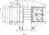
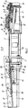
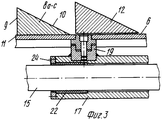
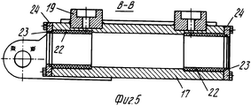
На фиг. 1 показан вид сверху на погрузочное устройство; на фиг. 2 - сечение А-А на фиг. 1; на фиг. 3 - транспортировочная плита; на фиг. 4 - вид Б на фиг. 1; на фиг. 5 - сечение В-В на фиг. 4. In FIG. 1 shows a top view of a loading device; in FIG. 2 is a section AA in FIG. 1; in FIG. 3 - shipping plate; in FIG. 4 is a view B in FIG. 1; in FIG. 5 is a cross-section BB in FIG. 4.
Погрузочное устройство состоит из погрузочной рампы 1 и транспортера 2, который входит своим головным концом в погрузочную рампу. Погрузочная рампа укреплена с помощью шарниров 3 на проходческом устройстве (не показано) и может в большей или меньшей степени поворачиваться вниз вокруг этих шарниров, в результате чего она аналогично лопатке может принимать лежащую на земле или падающую сверху породу или прочий материал. Погрузочная рампа 1 содержит раму 4, которая состоит из средней части 4а, в которой укреплена головная часть транспортера 2, и укрепленных сбоку на ней частей 4b и 4с. Боковые части 4b и 4с рамы оснащены закрывающими плитами 5b и 5с. Над закрывающими плитами на каждой стороне транспортера 2 установлена с возможностью возвратно-поступательных движений транспортировочная плита 6, к которой в прямом рабочем направлении проходческого комбайна плавно примыкает фартук 7 погрузочной рампы 1. The loading device consists of a
На транспортировочных плитах 6 укреплены транспортировочные балки 8 а-с, которые имеют треугольное поперечное сечение с обращенной к транспортеру 2 крутой боковой поверхностью 9 и полого возрастающей боковой поверхностью 10 на противоположной стороне. Крутая боковая поверхность 9 балки 8, расположенной перед транспортером, проходит приблизительно в контакте с передней кромкой 11 транспортировочной плиты 6. Поверхность части 4 в, которая открыта в изображенном положении транспортировочной плиты перед передней кромкой, закрыта закрывающей плитой 5b. Соответствующим образом в положении транспортировочной плиты, смещенном вперед к транспортеру 2, открытая за транспортировочной плитой часть 4 с рамы закрыта закрывающей плитой 5с. On the
Между двумя транспортировочными балками 8 с незначительным зазором и поперечно через транспортировочную плиту 6 проходят опорные балки 12, которые имеют аналогичное транспортировочным балкам поперечное сечение. Они укреплены на своих выступающих за транспортировочную плиту концах спереди через фартук 7 и позади через накладки 29 на раме 4. С помощью закрывающих кожухом 30 закрываются отверстия в задней стенке 31. Простирающиеся через фартук 7 концы транспортировочных 3 и опорных 12 балок оснащены сверху скосами 13 для того, чтобы они оказывали по возможности меньшее сопротивление поступающему на погрузочную рампу 1 транспортируемому материалу. Погрузочная рампа 1 содержит на своих внешних сторонах по одной опорной стенке 14, которая взаимодействует с наиболее далеко удаленной от транспортера 2 транспортировочной балкой 8 с так же, как опорные балки 12 взаимодействуют с транспортировочными балками 8а и 8b. Between the two transport beams 8 with a slight clearance and transversely through the
Транспортировочные плиты 6 укреплены с возможностью смещения на двух выполненных в качестве стержней направляющих рельсах 15. Для этой цели служит консоль 16 (см. фиг. 4), укрепленная ниже каждой транспортировочной плиты на последней, которая состоит из двух крепежных труб 17 и одной плиты 18, соединяющей их между собой. На верхней стороне предусмотрены крепежные патрубки 19 для транспортировочной плиты 6, а на нижней стороне - присоединительные устройства 20 для приводных средств 21. The
Крепежные патрубки 19 (фиг. 3) выполнены в качестве цапфовых соединений и встроены в транспортировочную плиту и крепежные трубы с целью защиты крепежных болтов от срезающих нагрузок. Fixing nozzles 19 (Fig. 3) are made as trunnion joints and are integrated into the transport plate and fixing pipes in order to protect the fixing bolts from shear loads.
Крепежные трубы 17 (фиг. 5) оснащены внутри втулками 22 из обеспечивающего скольжение материала. На концах крепежных труб с помощью кольцевых фланцев 24 укреплены съемные кольца 23. Fixing pipes 17 (Fig. 5) are equipped inside with
Приводные средства состоят из гидравлического агрегата, цилиндр 25 которого соединен с рамой 4 посредством накладок 27 и 28, а поршень соединен посредством рычажного механизма 26 с присоединительными устройствами 20 консоли 16 и, следовательно, с транспортировочной плитой 6. The drive means consist of a hydraulic unit, the
Устройство работает следующим образом. The device operates as follows.
Материал, поступающий в результате движения погрузочной рампы 1 вперед или в результате падения сверху на фартук 7 и транспортировочные плиты 6, поэтапно подводится к транспортеру 2 за счет возвратно-поступательных движений транспортировочных плит. При движении транспортировочных плит в направлении к транспортеру транспортировочные балки 8 сдвигают материал своей крутой боковой поверхностью 9 через стационарные опорные балки 12, а при их противоположном движении они проходят под материалом, который удерживается крутыми боковыми поверхностями опорных балок 12 или опорной стенки 14 и не может сместиться назад. При последующем движении вперед транспортировочных балок 8 прошедший до этого через транспортировочные балки материал вновь смещается через следующую опорную балку. The material resulting from the movement of the
Claims (13)
Applications Claiming Priority (2)
| Application Number | Priority Date | Filing Date | Title |
|---|---|---|---|
| DE4000200A DE4000200C1 (en) | 1990-01-05 | 1990-01-05 | |
| DE904000200 | 1990-01-05 |
Publications (1)
| Publication Number | Publication Date |
|---|---|
| RU2013556C1 true RU2013556C1 (en) | 1994-05-30 |
Family
ID=6397655
Family Applications (1)
| Application Number | Title | Priority Date | Filing Date |
|---|---|---|---|
| SU914894260A RU2013556C1 (en) | 1990-01-05 | 1991-01-04 | Broken rock loading device |
Country Status (6)
| Country | Link |
|---|---|
| US (1) | US5123520A (en) |
| EP (1) | EP0436187B1 (en) |
| AT (1) | ATE105826T1 (en) |
| DE (2) | DE4000200C1 (en) |
| PL (1) | PL165351B1 (en) |
| RU (1) | RU2013556C1 (en) |
Families Citing this family (27)
| Publication number | Priority date | Publication date | Assignee | Title |
|---|---|---|---|---|
| US5464426A (en) * | 1993-05-14 | 1995-11-07 | Bonutti; Peter M. | Method of closing discontinuity in tissue |
| US5718717A (en) | 1996-08-19 | 1998-02-17 | Bonutti; Peter M. | Suture anchor |
| US6045551A (en) | 1998-02-06 | 2000-04-04 | Bonutti; Peter M. | Bone suture |
| US6368343B1 (en) | 2000-03-13 | 2002-04-09 | Peter M. Bonutti | Method of using ultrasonic vibration to secure body tissue |
| US6447516B1 (en) | 1999-08-09 | 2002-09-10 | Peter M. Bonutti | Method of securing tissue |
| US6635073B2 (en) | 2000-05-03 | 2003-10-21 | Peter M. Bonutti | Method of securing body tissue |
| US7094251B2 (en) | 2002-08-27 | 2006-08-22 | Marctec, Llc. | Apparatus and method for securing a suture |
| US9138222B2 (en) | 2000-03-13 | 2015-09-22 | P Tech, Llc | Method and device for securing body tissue |
| US6719765B2 (en) | 2001-12-03 | 2004-04-13 | Bonutti 2003 Trust-A | Magnetic suturing system and method |
| US9155544B2 (en) | 2002-03-20 | 2015-10-13 | P Tech, Llc | Robotic systems and methods |
| US7497864B2 (en) | 2003-04-30 | 2009-03-03 | Marctec, Llc. | Tissue fastener and methods for using same |
| US20080039873A1 (en) | 2004-03-09 | 2008-02-14 | Marctec, Llc. | Method and device for securing body tissue |
| US9463012B2 (en) | 2004-10-26 | 2016-10-11 | P Tech, Llc | Apparatus for guiding and positioning an implant |
| US9271766B2 (en) | 2004-10-26 | 2016-03-01 | P Tech, Llc | Devices and methods for stabilizing tissue and implants |
| US9173647B2 (en) | 2004-10-26 | 2015-11-03 | P Tech, Llc | Tissue fixation system |
| US20060089646A1 (en) | 2004-10-26 | 2006-04-27 | Bonutti Peter M | Devices and methods for stabilizing tissue and implants |
| US9089323B2 (en) | 2005-02-22 | 2015-07-28 | P Tech, Llc | Device and method for securing body tissue |
| US8496657B2 (en) | 2006-02-07 | 2013-07-30 | P Tech, Llc. | Methods for utilizing vibratory energy to weld, stake and/or remove implants |
| US11278331B2 (en) | 2006-02-07 | 2022-03-22 | P Tech Llc | Method and devices for intracorporeal bonding of implants with thermal energy |
| US7967820B2 (en) | 2006-02-07 | 2011-06-28 | P Tech, Llc. | Methods and devices for trauma welding |
| US11253296B2 (en) | 2006-02-07 | 2022-02-22 | P Tech, Llc | Methods and devices for intracorporeal bonding of implants with thermal energy |
| US11246638B2 (en) | 2006-05-03 | 2022-02-15 | P Tech, Llc | Methods and devices for utilizing bondable materials |
| US8617185B2 (en) | 2007-02-13 | 2013-12-31 | P Tech, Llc. | Fixation device |
| WO2010099222A1 (en) | 2009-02-24 | 2010-09-02 | P Tech, Llc | Methods and devices for utilizing bondable materials |
| US10076377B2 (en) | 2013-01-05 | 2018-09-18 | P Tech, Llc | Fixation systems and methods |
| US9452888B2 (en) * | 2013-02-19 | 2016-09-27 | Sterling Wayne Lowery | High volume loading and stacking apparatus and method |
| US10058393B2 (en) | 2015-10-21 | 2018-08-28 | P Tech, Llc | Systems and methods for navigation and visualization |
Family Cites Families (10)
| Publication number | Priority date | Publication date | Assignee | Title |
|---|---|---|---|---|
| US2257181A (en) * | 1939-11-24 | 1941-09-30 | Timothy F Mccarthy | Combined cutting and loading machine |
| US2543519A (en) * | 1946-08-22 | 1951-02-27 | Joy Mfg Co | Material handling apparatus |
| SE308889B (en) * | 1967-11-15 | 1969-02-24 | Mo Och Domsjoe Ab | |
| US3680920A (en) * | 1970-10-07 | 1972-08-01 | Lee Norse Co | Material collecting means for mining machines |
| DE2441567A1 (en) * | 1974-08-30 | 1976-03-18 | Wilhelm Kroeber | FLAT CONTAINER FOR FILM REELS AND THE LIKE |
| DE2554274A1 (en) * | 1975-12-03 | 1977-06-16 | Gewerk Eisenhuette Westfalia | Conveyor for winning tool in mining - has rigid drivers with gently rising rear surfaces and return flow restrictors between |
| DE2849141A1 (en) * | 1978-11-13 | 1980-05-22 | Schwaebische Huettenwerke Gmbh | BUNKER DISCHARGE DEVICE, IN PARTICULAR FOR HEAVY-FLOWING SHUBLE GOODS |
| DE3304908A1 (en) * | 1983-02-12 | 1984-08-16 | Gewerkschaft Eisenhütte Westfalia, 4670 Lünen | Loading device for the loading of debris, especially in shield driving |
| AT380926B (en) * | 1984-10-29 | 1986-07-25 | Voest Alpine Ag | LOADING DEVICE FOR TRACK DRIVING MACHINES |
| DE3546192A1 (en) * | 1985-12-27 | 1987-07-02 | Gewerk Eisenhuette Westfalia | LOADING DEVICE, IN PARTICULAR FOR PARTIAL CUTTING MACHINES |
-
1990
- 1990-01-05 DE DE4000200A patent/DE4000200C1/de not_active Expired - Fee Related
- 1990-12-17 PL PL90288301A patent/PL165351B1/en unknown
- 1990-12-20 EP EP90124881A patent/EP0436187B1/en not_active Expired - Lifetime
- 1990-12-20 DE DE59005742T patent/DE59005742D1/en not_active Expired - Fee Related
- 1990-12-20 AT AT90124881T patent/ATE105826T1/en not_active IP Right Cessation
-
1991
- 1991-01-04 RU SU914894260A patent/RU2013556C1/en active
- 1991-01-04 US US07/637,471 patent/US5123520A/en not_active Expired - Fee Related
Also Published As
| Publication number | Publication date |
|---|---|
| PL288301A1 (en) | 1991-09-23 |
| EP0436187A1 (en) | 1991-07-10 |
| US5123520A (en) | 1992-06-23 |
| DE4000200C1 (en) | 1991-05-23 |
| DE59005742D1 (en) | 1994-06-23 |
| ATE105826T1 (en) | 1994-06-15 |
| PL165351B1 (en) | 1994-12-30 |
| EP0436187B1 (en) | 1994-05-18 |
Similar Documents
| Publication | Publication Date | Title |
|---|---|---|
| RU2013556C1 (en) | Broken rock loading device | |
| US4402392A (en) | Portable belt conveyor, particularly a plate belt conveyor for crushing plants | |
| CA2169606C (en) | Reciprocating floor conveyor and floor member | |
| US5653570A (en) | Stair-like log feeder | |
| US4373757A (en) | Conveyor trough for a scraper conveyor for use with a mining machine | |
| US4026408A (en) | Chip conveyor | |
| US4781284A (en) | Cleaning of a drum | |
| US5931540A (en) | Drive system having a pin drive chain for a cutting machine for underground mining | |
| SU1553472A1 (en) | Device for sealing transfer place of belt conveyer | |
| SU1735580A1 (en) | Face complex | |
| US3842964A (en) | Resiliently mounted swingable side plates for loading machines and the like | |
| RU1804559C (en) | Continuous miner | |
| RU2046745C1 (en) | Metal transportation conveyor | |
| SU1430543A1 (en) | Machinery set for driving machine mounting stables | |
| DE10115071C2 (en) | Gutauforgan for a continuous ship unloader | |
| SU960099A1 (en) | Flight conveyer | |
| SU607055A1 (en) | Loading machine | |
| SU1155543A1 (en) | Loader for loose materials | |
| GB2053119A (en) | Removal of rock and the like from a conveyor | |
| SU636418A1 (en) | V.m.panov's face conveyer | |
| SU1082727A2 (en) | Loading machine | |
| SU451864A1 (en) | Telescopic belt conveyor | |
| RU2209756C2 (en) | Scraper conveyor telescopic device | |
| SU899441A1 (en) | Load transfer arrangement | |
| SU1214549A1 (en) | Apron conveyer |