KR970008599B1 - Means for controlling wire in a paper machine or cardboard machine - Google Patents
Means for controlling wire in a paper machine or cardboard machine Download PDFInfo
- Publication number
- KR970008599B1 KR970008599B1 KR1019880011537A KR880011537A KR970008599B1 KR 970008599 B1 KR970008599 B1 KR 970008599B1 KR 1019880011537 A KR1019880011537 A KR 1019880011537A KR 880011537 A KR880011537 A KR 880011537A KR 970008599 B1 KR970008599 B1 KR 970008599B1
- Authority
- KR
- South Korea
- Prior art keywords
- wire
- strip
- strips
- bellows
- wires
- Prior art date
Links
Images


Classifications
-
- D—TEXTILES; PAPER
- D21—PAPER-MAKING; PRODUCTION OF CELLULOSE
- D21F—PAPER-MAKING MACHINES; METHODS OF PRODUCING PAPER THEREON
- D21F9/00—Complete machines for making continuous webs of paper
-
- D—TEXTILES; PAPER
- D21—PAPER-MAKING; PRODUCTION OF CELLULOSE
- D21F—PAPER-MAKING MACHINES; METHODS OF PRODUCING PAPER THEREON
- D21F1/00—Wet end of machines for making continuous webs of paper
- D21F1/48—Suction apparatus
-
- D—TEXTILES; PAPER
- D21—PAPER-MAKING; PRODUCTION OF CELLULOSE
- D21F—PAPER-MAKING MACHINES; METHODS OF PRODUCING PAPER THEREON
- D21F1/00—Wet end of machines for making continuous webs of paper
- D21F1/36—Guiding mechanisms
- D21F1/38—Pads
-
- D—TEXTILES; PAPER
- D21—PAPER-MAKING; PRODUCTION OF CELLULOSE
- D21F—PAPER-MAKING MACHINES; METHODS OF PRODUCING PAPER THEREON
- D21F9/00—Complete machines for making continuous webs of paper
- D21F9/003—Complete machines for making continuous webs of paper of the twin-wire type
Abstract
Description
제1도는 본 발명이 적용된 제지기의 이중 와이어부를 나타낸 단면도.1 is a cross-sectional view showing a double wire portion of the paper machine to which the present invention is applied.
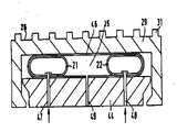
제2도는 제1도의 단면과 일치하는 단면으로 본 발명에 따른 1개의 스트립 및 보조 제어 부재를 나타낸 확대단면도.FIG. 2 is an enlarged cross-sectional view showing one strip and the auxiliary control member according to the invention in a cross section coinciding with the cross section in FIG.
제3도는 제2도의 좌측에 있는 보조 제어 부재의 일부를 나타낸 확대도.3 is an enlarged view showing a part of the auxiliary control member on the left side of FIG.
제4도는 제1도의 단면과 일치하는 단면으로 보조 제어 부재의 제1변형 실시예를 나타낸 단면도.4 is a cross-sectional view showing a first modified embodiment of the auxiliary control member in a cross section coinciding with the cross section in FIG.
제5도는 제1도의 단면과 일치하는 단면으로 보조 제어 부재의 제2변형 실시예를 나타낸 단면도.FIG. 5 is a cross-sectional view showing a second modified embodiment of the auxiliary control member in a section consistent with the cross section in FIG.
제6도 및 제7도는 제2도의 A-A선을 따라 취한 힘 공급 부재의 여러 실시예의 개략적인 단면도.6 and 7 are schematic cross-sectional views of various embodiments of a force supply member taken along line A-A of FIG.
* 도면의 주요부분에 대한 부호의 설명* Explanation of symbols for main parts of the drawings
2 : 상부 와이어3, 4, 5, 6: 전향 롤2: upper wire 3, 4, 5, 6: roll forward
7 : 하부 와이어8 : 입구부7: lower wire 8: inlet
9 : 이송 방향10 : 탈수 박스9: conveying direction 10: dehydration box
11 : 도관12 : 바닥부11: conduit 12: bottom
13 : 지지 테이블14 : 스탠드13: support table 14: stand
15 : 압력 부재16, 31, 32 : 스트립15:
18 : 홈19, 20, 21, 22, 23, 24 : 힘 공급 부재18: groove 19, 20, 21, 22, 23, 24: power supply member
33 : 지지 힐37 : 고정 부재33: support heel 37: fixed member
I, II, III : 챔버I, II, III: chamber
본 발명은 제지기 또는 판지 제조기에서 와이어를 제어하기 위한 수단에 관한 것이다.The present invention relates to means for controlling wires in paper machines or paperboard machines.
보다 상세하게, 본 발명은, 와이어가 상하로 평행하게 주행하고 이들 와이어 사이로 제지 재료가 도입되어 탈수되는 이중 와이어부(twin-wire section)에서, 와이어를 제어하는 것에 관한 것이다. 통상, 상부 와이어 위에는 탈수 박스가 설치되며, 탈수 박스내에는 제지 재료로 부터 압착된 물을 흡인하기 위해 부분적인 진공 상태가 유포된다. 하부 와이어 아래에는 탈수 박스에 대해 고정된 지지 테이블 또는 그 균등물이 설치된다.More specifically, the present invention relates to the control of a wire in a twin-wire section in which the wire runs up and down in parallel and the papermaking material is introduced and dehydrated between these wires. Typically, a dehydration box is installed above the upper wire, and a partial vacuum is spread in the dehydration box to draw water squeezed from the papermaking material. Underneath the lower wire is a support table or its equivalent fixed to the dehydration box.
이러한 형태의 기계에서는, 한편으로 와이어 사이에 형성되는 틈새의 두께를 변경시킬 수 있고, 다른 한편으로 와이어의 이송 방향으로 상기 틈새의 공간 형상을 변경시킬 수 있는 것이 바람직하고, 또한 필요하다.In this type of machine, it is desirable and necessary to be able to change the thickness of the gap formed between the wires on the one hand and to change the space shape of the gap in the conveying direction of the wire on the other hand.
이를 위해, 하부 와이어를 탈수 박스에 맞대어 놓여 있는 상부 와이어쪽을 향해 위쪽으로 가압하는 제어부재가 설치된다.For this purpose, a control member is provided which presses the lower wire upwards toward the upper wire lying against the dehydration box.
즉, 상기 제어 부재가 지지 테이블과 하부 와이어 사이에서 작용한다.In other words, the control member acts between the support table and the lower wire.
스웨덴 특허 제8501985.9호 및 그 대응 독일 특허 제3,406,217호에는, 옆으로 나란하게 밀접 위치되어 와이어의 전폭에 걸쳐 연장되는 다수의 스트립을 구비하고, 이들 스트립이 하부 와이어에 맞대어 놓이고, 하부 와이어에 맞대어 가압되는 스트립의 압력이 조절될 수 있는, 와이어 제어 트랙이 개시되어 있다. 상기 스트립은 하부 와이어를 향해, 또한 와이어로부터 떨어지도록 이동될 수 있으나, 와이어의 이송면에 맞닿는 스트립 상단면의 각도는 조절이 불가능하다.Swedish Patent No. 8501985.9 and its corresponding German Patent No. 3,406,217 have a plurality of strips which are placed side by side closely and extending over the full width of the wire, these strips against the lower wire and against the lower wire A wire control track is disclosed in which the pressure of the strip being pressed can be adjusted. The strip may be moved towards the lower wire and away from the wire, but the angle of the top surface of the strip against the conveying surface of the wire is not adjustable.
상기 스웨덴 특허 제8501985.9호에 기재된 과제 해결 방안은 번거롭게도 스트립이 밀접하게 합쳐져 놓여야 하는 단점을 가진다. 이것은 스트립이 마찰을 통해 상호 작용하게 되는 결과를 가져오며, 이로 인해 제어가 방해를 받는다. 이러한 방해는 하부 와이어와의 마찰로 인해 스트립이 경사진 위치를 취하는 경향을 가짐으로써 스트립의 상부면이 와이어의 이송면에 대해 완전히 평행하게 되지 못한다는 사실을 통해 보다 가중된다. 또한, 스트립이 흡인용 슬릿 또는 그 균등물을 구비하도록 구성되지 않는 한, 상기 수단에서는 액체가 아래쪽으로 방출될 수 없다.The problem solution described in Swedish Patent No. 8501985.9 has the disadvantage that the strips must be placed in close integration. This results in the strips interacting through friction, which interrupts control. This obstruction is further aggravated by the fact that the top surface of the strip is not completely parallel to the conveying surface of the wire by having a tendency for the strip to be inclined due to friction with the lower wire. In addition, the liquid cannot be discharged downward in the above means unless the strip is configured to have a suction slit or an equivalent thereof.
독일 특허 제3,153,305호에는, 하부 와이어에 맞대어 놓인 서로 이격된 다수의 스트립이 설치된 또 다른 와이어 제어 트랙이 개시되어 있다. 이들 스트립에서는, 하부 와이어에 맞대어 가압되는 그 압력이 스프링 부재에 의해 별개로 조절된다. 그러나, 각각의 스트립은 특정 스트립에 배정된 스프링 부재에 선회 가능하게 연결되기 때문에, 수평면에 대한 스트립 상단면의 위치는 조절 불가능하다. 즉, 이 독일 특허에 따르면, 하부 와이어와 스트립 사이의 마찰로 인해, 하부 와이어의 표면에 대해 경사진 스트립 상단면의 위치를 보상하는 것이 불가능하다.German Patent No. 3,153, 305 discloses another wire control track which is provided with a plurality of spaced apart strips against the lower wire. In these strips, the pressure that is pressed against the lower wire is separately controlled by the spring member. However, since each strip is pivotally connected to a spring member assigned to a particular strip, the position of the strip top surface relative to the horizontal plane is not adjustable. That is, according to this German patent, due to the friction between the lower wire and the strip, it is impossible to compensate for the position of the inclined strip top surface with respect to the surface of the lower wire.
따라서, 와이어에 맞대어 가압되는 압력을 조절하고, 이에 의해 제지 재료에 맞대어 가압되는 압력을 조절하기 위한 여러 해결 방안들이 당해 기술 분야에 공지되어 있다.Accordingly, several solutions are known in the art for adjusting the pressure pressed against the wire and thereby adjusting the pressure pressed against the papermaking material.
이중 와이어부에서 제지 재료를 탈수시키는 것과 관련된 최적의 기능성을 얻기 위해서는, 이송 방향으로의 스트립 전방 단부를 가압하는 압력과 그 후방 단부를 가압하는 압력이 별개로 조절될 수 잇는 것이 필수적인 것으로 판명되었다.In order to obtain the optimum functionality associated with dewatering the papermaking material in the double wire portion, it has been found that the pressure for pressing the strip front end in the conveying direction and the pressure for pressing the rear end thereof can be adjusted separately.
이와 같이 함으로써, 각각의 스트립에 대해 임의의 원하는 압력 분포 형태(pressure profile)가 설정될 수 있다. 또한, 진술된 바와 같이 경사져 위치되는 것이 배제될 수 있다.By doing so, any desired pressure profile can be set for each strip. It can also be excluded to be inclined as stated.
본 발명은 바로 직전에 설명된 바를 달성할 수 있게 해주는 수단을 개시한다.The present invention discloses means which enable to achieve what has just been described.
또한, 이러한 수단의 구성은 간단하고 견고하다.In addition, the configuration of such means is simple and robust.
즉, 본 발명은, 2개의 와이어가 그 사이에 있는 제지 재료를 탈수시키기 위해 상하로 배치되어 주행하며, 일측 와이어에 탈수 박스가 설치되고 타측 와이어에 옆으로 나란하게 배치된 다수의 스트립이 설치되며, 상기 스트립이 서로 평행하게 이격되어 배치되고 와이어의 이송 방향을 가로질러 와이어의 전폭에 걸쳐 주행하며, 상기 스트립이 압력 부재에 의해 그에 가장 인접하게 위치된 와이어에 맞대어 가압되도록 배치되며, 상기 압력 부재가 탈수 박스에 대해 고정적으로 설치된 지지 테이블 또는 그 균등물과 스트립 사이에서 작용하도록 배치되는, 제지기 또는 판지 제조기의 이중 와이어부에서 와이어를 제어하기 위한 수단에 관한 것으로, 이러한 수단은 각각의 스트립에 별개의 부재가 설치되며, 각각의 압력 부재가 각각의 스트립과 지지테이블 사이에 설치된 2개 이상의 힘 공급 부재를 구비하며, 상기 힘 공급 부재가 탈 수 박스를 향한 방향 및 탈수 박스로 부터 멀어지는 방향으로 스트립을 이동시키도록 배치되며, 상기 힘 공급 부재 중 제1부재가 와이어의 이송 방향으로의 스트립 후방 단부에 맞대어 작용하도록 배치되고 상기 힘 공급 부재중 제2부재가 와이어의 이송방향으로의 스트립 후방 단부에 맞대어 작용하도록 배치되며, 상기 힘 공급 부재가 한편으로 와이어에 맞대어 가압되는 스트립의 압력이 조절 될 수 있고 다른 한편으로 와이어에 대한 스트립 상단면의 각도가 조절될 수 있도록 별개로 제어될 수 있는 것을 특징으로 한다.That is, the present invention, the two wires are arranged to run up and down to dewater the papermaking material between them, a dehydration box is installed on one wire and a plurality of strips arranged side by side on the other wire is installed The strips are arranged so as to be spaced apart parallel to each other and travel across the full width of the wire across the conveying direction of the wires, the strips being arranged to be pressed against the wires positioned most adjacent thereto by the pressure members, Means for controlling the wire in a double wire section of a paper machine or paperboard machine, which is arranged to act between a support table or its equivalent fixedly mounted to the dehydration box and the strip, the means being connected to each strip. Separate members are installed, and each pressure member has its own strip and support table Two or more force supply members disposed therebetween, the force supply members being arranged to move the strip in a direction toward the dehydration box and away from the dewatering box, the first member of the force supply member being a wire; The second member of the force supply member is arranged to act against the strip rear end in the conveying direction of the wire, and the force supply member is pressed against the wire on the one hand. The pressure of the strip can be adjusted and on the other hand it can be controlled separately so that the angle of the top surface of the strip with respect to the wire can be adjusted.
이하, 본 발명의 실시예들을 도시하고 있는 첨부 도면을 참조하여 본 발명을 보다 상세히 설명한다.Hereinafter, with reference to the accompanying drawings showing embodiments of the present invention will be described in more detail the present invention.
제1도에는 제지기의 이중 와이어부(1)가 입면도로 도시되어 있으며, 이러한 와중 와이어부(1)에서는 상부 와이어(2)가 전향롤(3, 4, 5, 6)을 거쳐 주행하고 있고, 하부 와이어(7)가 상부 와이어(7)에 대략 평행하게 그 상부 와이어(7) 아래에서 주행하고 있다. 이들 와이어(2, 7)는 제지 재료가 점진적으로 압축되는 웨지형 입구부(8)를 형성한다. 제1도에는 다수의 작동 설정 부재가 또한 도시되어 있으며, 이들 부재들은 당해 기술 분야에서 공지된 형태의 것들이므로, 이들을 상세히 설명하지는 않는다.In FIG. 1, the double wire part 1 of the papermaking machine is shown in elevation, in which the upper wire 2 is traveling through the turning rolls 3, 4, 5, and 6 in this heavy wire part 1; , The lower wire 7 runs below the upper wire 7 substantially parallel to the upper wire 7. These wires 2, 7 form a wedge shaped inlet 8 into which the papermaking material is gradually compressed. Also shown in FIG. 1 are a number of actuation setting members, which are of a type known in the art and are not described in detail.
웨지형 입구부(8)에 후속하여 이송 방향(9)으로 탈수 주행부가 설치되며, 이 탈수 주행부는 상이한 정도의 진공 상태를 가진 3개의 참버(I, II, III)를 포함하는 탈수 박스(10)를 구비한다. 제지 재료로 부터 나온 물은 도관(11)에 의해 챔버로 인출된다. 도관(11)은 탈수 박스(10)의 바닥부(12)에 들어 있으며, 상부 와이어(7)는 이 바닥부(12)에 맞대어 주행한다.Subsequent to the wedge-shaped inlet 8, a dewatering run is provided in the conveying direction 9, which dewatering box 10 comprises three chambers I, II and III with different degrees of vacuum. ). Water from the papermaking material is withdrawn into the chamber by
하부 와이어(2)의 아래에는 탈수 박스(10)에 대해 고정 장착된 지지 테이블(13)이 설치되며, 이 지지 테이블(13)은 전체적으로 도면 부호 14로 지시된 스탠드상에 유지된다.Underneath the lower wire 2, a support table 13 fixedly mounted to the dehydration box 10 is provided, which is held on the stand indicated by reference numeral 14 as a whole.
지지 테이블(13)상에는 다수의 압력 부재(15) 형태의 제어 부재가 설치되며, 이들 압력 부재(15)는 각각 제1도의 위쪽으로 스트립(16)을 가압함으로써 스트립(16)이 하부 와이어(2)에 맞대어 압력을 가하고, 이에 의해 제지 재료에 맞대어 압력을 가하도록 배치된다.A control member in the form of a plurality of
즉, 그중 하나가 제2도에 확대 도시되어 있는 상기 압력 부재(15)는 스트립(16)의 하측면과 지지 테이블(13) 사이에 배치된다. 전술된 바와 같이, 스트립 상단면은 하부 와이어(7)에 맞대어 놓이도록 배치된다.That is, the
스트립(16)은 제지 재료로 부터 나온 물을 배수하기 위한 홈(18)을 구비한다.The
본 발명에 따르면, 각각의 스트립(16)에 대해 별개의 압력 부재(15)가 설치되며, 각각의 압력 부재(15)는 각각의 스트립(16)과 지지 테이블(13) 사이에 2개 이상의 힘 공급 부재(19, 20, 21, 22, 23, 24)를 구비한다. 힘 공급 부재(19-24)는 스트립을 탈수 박스(10)를 향한 방향 및 탈수 박스(10)로 부터 멀어지는 방향으로 이동시키도록 배치된다. 힘 공급 부재중 제1부재(19, 21, 23)는 와이어의 이송 방향으로의 각각의 스트립(16, 31, 32) 전방 단부에 맞대어 작용하도록 배치되며, 힘 공급 부재중 제2부재(20, 23, 24)는 와이어의 이송 방향으로의 각각의 스트립(16, 31, 32) 후방 단부에 맞대어 작용하도록 배치된다.According to the invention, a
또한, 힘 공급 부재(19-24)는 한편으로 하부 와이어에 맞대어 가압되는 스트립의 압력이 조절될 수 있고 다른 한편으로 하부 와이어에 대한 스트립 상단면의 각도가 조절될 수 있도록 별개로 제어될 수 있다.In addition, the force supply members 19-24 may be separately controlled such that the pressure of the strip being pressed against the lower wire on the one hand may be adjusted and on the other hand the angle of the strip top surface relative to the lower wire may be adjusted. .
적합한 실시예에 따르면, 스트립(16, 31, 32)은 서로 이격되어 서로에 평행하게 배치된다. 스트립 사이의 간격은 와이어의 이송 방향으로의 스트립 폭의 일부에 불과하다.According to a suitable embodiment, the
이에 의해, 스트립이 서로 매우 밀접하게 배치되었던 경우에서와 같이 스트립이 서로 걸리거나 함께 밀착되게 놓임으로써 서로에 영향을 미치게 되는 것이 배제될 수 있다.By this, it can be ruled out that the strips are stuck to each other or placed in close contact with each other, such as in the case where the strips are arranged very closely to each other, thereby affecting each other.
즉, 명백하게 본 발명은 서두에 언급된 선행 기술 수단의 단점을 완전히 해소하게 된다.In other words, the present invention clearly obviates the disadvantages of the prior art means mentioned at the outset.
따라서, 본 발명은 각각의 스트립이 별개로 조절 가능하여 이중 와이어부의 제어 트랙이 최적으로 제어될 수 있도록 해준다.Thus, the present invention allows each strip to be individually adjustable so that the control track of the double wire portion can be optimally controlled.
본 발명의 특히 적합한 실시예에 따르면, 힘 공급 부재는 압축 공기에 의해 제어되도록 배치된 고무 벨로우즈 또는 그 균등물을 구비한다.According to a particularly suitable embodiment of the invention, the force supply member has a rubber bellows or its equivalent arranged to be controlled by compressed air.
제2도에는 제1도에 도시된 실시예에 대응하는 본 발명의 제1실시예가 도시되어 있다.FIG. 2 shows a first embodiment of the present invention corresponding to the embodiment shown in FIG.
본 실시예에 따르면, 지지 테이블(13)은 지지 테이블(13)의 유지 프레임(34)상에 장착된 지지 휠(33; supporting heel)을 구비한다.According to the present embodiment, the support table 13 has a supporting
제2도에 도시된 실시예에 따르면, 각각의 힘 공급 부재는 고무 벨로우즈(19, 20)로 구성되며, 압력 부재의 길이 방향을 횡단하는 단면에서 보았을 때 고무 벨로우즈(19, 20)는 웨지 형상을 가지고, 스트립(16)과 지지 테이블(13) 사이에서 함께 대략 사각형의 필로우(pillow)를 형성하도록 서로 상하로 대향된 채 맞대어 배치된다.According to the embodiment shown in FIG. 2, each of the force supply members consists of rubber bellows 19, 20, and the rubber bellows 19, 20 are wedge shaped when viewed in a cross section transverse to the longitudinal direction of the pressure member. And are arranged face to face up and down with each other to form a substantially rectangular pillow together between the
고무 벨로우즈는 섬유보강 고무재 또는 그와 균등한 특성을 가진 재료로 제작되는 것이 적합하다.The rubber bellows is suitably made of fibre-reinforced rubber or materials with equivalent properties.
서로 대향된 벨로우즈(19, 20)의 양 측면(35, 36)사이에는 판 형상의 고정 부재(37)가 설치된다. 고정 부재(37)의 일측 가장자리부(38)는 지지 테이블(13(33))에 일체로 연결되고, 고정 부재(37)의 타측 가장자리부(39)는 스트립(16)에 일체로 연결된다.A plate-shaped fixing
제3도에는 제2도의 좌측에 있는 고정 부분이 확대도로 도시되어 있다. 제3도에는 하부 벨로우즈(20)의 좌측 가장자리가 지지 테이블(13)과의 나사식 결합에 의해 소정의 위치에 고정되는 것이 또한 도시되어 있다. 도면 부호 40은 플라스틱제 또는 금속제 클램프를 지시하고, 도면 부호 41은 나사를 지시한다.In FIG. 3, the fixing part on the left side of FIG. 2 is shown in an enlarged view. 3 also shows that the left edge of the lower bellows 20 is fixed in position by threaded engagement with the support table 13.
고정 부재도 또한 섬유 보강 고무재로 제작될 수 있으나, 박판 금속으로 제작될 수도 있다.The fixing member may also be made of fiber reinforced rubber, but may also be made of sheet metal.
제2도에는 압축 공기를 벨로우즈(19, 20)로 도입하고 벨로우즈(19, 20)로 부터 배출하기 위한 니플(42, 42')이 파선에 의해 개략적으로 도시되어 있다. 이들 니플(42, 42')은 벨로우즈의 각각의 단부에 배치되는 것이 적합하다.2 schematically shows the
벨로우즈(19)내의 압력이 벨로우즈(20)내의 압력보다 높게 될 때까지 압축 공기가 벨로우즈(19)에 도입되면, 스트립(16)의 좌측 단부, 즉 그 전방 단부가 스트립(16)의 우측 단부, 즉 그 후방 단부보다 상승될 것임은 자명하다. 이것은 제2도에서 파선(43)에 의해 예시되어 있다.When compressed air is introduced into the
스트립(16)의 하측면과 지지 힐(33)의 상단면에 인접한 벨로우즈의 표면은 그 각각의 표면에 부착되는 것이 적합하다. 이것은 기계적 접합에 의해 수행되거나 벨로우즈를 결합재에 의해 그 각각의 표면에 결합시킴으로써 수행될 수 있다.The surface of the bellows adjacent the lower side of the
제4도 및 제5도에는 적합한 다른 변형 실시예가 도시되어 있다.Other suitable embodiments are shown in FIGS. 4 and 5.
이들 실시예에 따르면, 그 각각의 스트립(31, 32)과 지지 테이블(44, 45)은 부분적으로 서로에 둘러싸이게 되며, 이에 따라 스트립(31,32)의 지지 테이블(44, 45)에 대한 이동성이 제한될 수 밖에 없다. 이러한 실시예에 의해, 제2도와 관련하여 바로 직전에 설명된 형태의 고정 부재가 전혀 필요 없게 된다.According to these embodiments, the
제4도에 도시된 실시예에 따르면, 그 내부에 전술된 바와 같은 2개의 벨로우즈(21, 22)를 수납하고 있는 추가의 벨로우즈(46)가 설치된다. 이들 내부 벨로우즈(21, 22)는 외부 벨로우즈(46)에 고정되며, 외부 벨로우즈(46) 자체는 기계적 접합 또는 결합제에 의한 결합에 의해 스트립(31) 및 지지 테이블(44)에 부착되는 것이 적합하다.According to the embodiment shown in FIG. 4, there are provided
압축 공기의 도입 및 배기에 사용되는 도관은 각각의 내부 벨로우즈(21, 22)에 설치된다.Conduits used for the introduction and exhaust of compressed air are provided in the respective inner bellows 21, 22.
제4도로 부터 알 수 있는 바와 같이, 스트립은 제4도의 좌우 방향으로 매우 짧은 거리에 걸쳐서만 한정적으로 이동된다. 또한, 스트립은 한정적이지만 좌우 방향으로의이동 거리보다는 긴 거리에 걸쳐 제4도의 상하 방향으로 이동된다. 사실상, 스트립이 좌우 방향으로 이동 될 수 있는 여지는 없다. 스트립과 지지 테이블 사이에 있는 개방 틈새는 단지 스트립의 상하 방향으로의 이동 및 스트립 상단면의 경사 위치 조절을 보다 용이하게 하기 위한 것에 불과하다.As can be seen from FIG. 4, the strip is only moved over a very short distance in the lateral direction of FIG. 4. Further, the strip is limited but moved in the up and down direction of FIG. 4 over a longer distance than the travel distance in the left and right directions. In fact, there is no room for the strip to move in the left and right directions. The opening gap between the strip and the support table is merely to make it easier to move the strip in the vertical direction and adjust the inclined position of the strip top surface.
외부 벨로우즈와 외부 대기 사이를 연통시키는 도관(49)이 설치되어야 한다. 그러나, 그 대안으로, 외부 벨로우즈의 단부들이 개방될 수도 있다.
제5도에는 제4도의 실시예에 상응하는 실시예가 도시되어 있으며, 본 실시예는 2개의 벨로우즈(23, 24)가 유지 부재(50, 51)에 의해 스트립(32) 및 지지 테이블에 속한 부분(45)에 대해 고정되는 것을 특징으로 한다.5 shows an embodiment corresponding to the embodiment of FIG. 4, in which the two bellows 23, 24 belong to the
본 실시예에 따르면, 마찬가지로 스트립은 지지 테이블에 대해 한정적으로 이동될 수 있다. 또한, 압축 공기의 공급 및 배출을 위해 도관(52, 53)이 설치된다.According to this embodiment, the strip can likewise be limitedly moved relative to the support table. In addition,
제4도 및 제5도와 관련하여 설명된 실시예들에 따르면, 역시 벨로우즈(21, 22, 46, 23, 24)는 섬유 보강고무재로 제작되는 것이 적합하다.According to the embodiments described in connection with FIGS. 4 and 5, it is also suitable for the
스트립은 적절한 내마모성을 가진 특정 재료로 제작된다.The strip is made of a specific material with adequate wear resistance.
제6도에 도시된 실시예에 따르면, 모든 벨로우즈(19)는 스트립(16)의 총길이와 일치하는 길이를 가진다. 그러나, 또 다른 실시예에 따르면, 스트립(16)을 유지하는 벨로우즈 중 1개 또는 2개는 그 길이 방향으로 연이어 배치된 2개 이상의 벨로우즈(19', 19'', 19''')로 구성될 수 있으며, 이에 따라 제7도에 도시된 바와 같이, 벨로우즈(19', 19'', 19''')가 함께 스트립(16)이 총길이와 일치하는 길이를 가진 공급 부재를 형성하게 된다. 이 경우, 모든 벨로우즈(19', 19'', 19''')는 압축 공기를 공급하고 배출하는 니플을 구비한다. 각각의 벨로우즈(19', 19'', 19''')는 별개로 조절될 수 있다.According to the embodiment shown in FIG. 6, all bellows 19 have a length that matches the total length of the
본 실시예는 와이어(7)의 진폭에 걸쳐 압력 분포 형태를 제어하는 것이 가능하다는 의미를 내포하고 있다.This embodiment implies that it is possible to control the pressure distribution pattern over the amplitude of the wire 7.
또 다른 변형실시예에 따르면, 와이어의 전 길이에 걸쳐 길게 연장된 벨로우즈가 상이한 구간으로 세분될 수도 있다.According to another variant, the bellows extending over the entire length of the wire may be subdivided into different sections.
이상, 여러 예시적인 실시예들을 설명하였다.In the above, various exemplary embodiments have been described.
벨로우즈가 제2도, 제3도 및 제4도의 단면도에 도시된 바와는 상이한 형상을 가지고, 스트립의 하측면 및 지지 테이블의 상단면의 도시된 것보다 더 크거나 작은 부분에 걸쳐 연장될 수 있음은 자명하다. 또한, 벨로우즈는 전술된 바와는 다른 것으로 해당 용도에 적절한 재료로 제작될 수 있다.The bellows has a different shape than that shown in the cross-sectional views of FIGS. 2, 3 and 4 and can extend over a portion larger or smaller than that shown in the lower side of the strip and the upper side of the support table. Is self explanatory. In addition, the bellows can be made of a material suitable for the application, other than as described above.
물론, 스트립 및 지지 테이블도 전술된 바와는 다르게 실시될 수 있다.Of course, the strip and support table can also be implemented differently than described above.
또한, 고정 부재(37)는 금속으로 제작될 경우 스프링 부재를 형성할 수 있다.In addition, the fixing
따라서, 본 발명의 전술된 실시예에 제한되는 것이 아니며, 이하의 청구 범위에 기재된 범위내에서 변경될 수 있는 것임은 자명하다.It is, therefore, to be understood that the invention is not limited to the above-described embodiment, but may be modified within the scope of the following claims.
Claims (7)
Applications Claiming Priority (2)
| Application Number | Priority Date | Filing Date | Title |
|---|---|---|---|
| SE8703468A SE456590B (en) | 1987-09-07 | 1987-09-07 | DEVICE FOR CONTROL OF VIRUSES IN A PAPER MACHINE OR CARTON MACHINE |
| SE8703468-2 | 1987-09-07 |
Publications (2)
| Publication Number | Publication Date |
|---|---|
| KR890005347A KR890005347A (en) | 1989-05-13 |
| KR970008599B1 true KR970008599B1 (en) | 1997-05-27 |
Family
ID=20369499
Family Applications (1)
| Application Number | Title | Priority Date | Filing Date |
|---|---|---|---|
| KR1019880011537A KR970008599B1 (en) | 1987-09-07 | 1988-09-07 | Means for controlling wire in a paper machine or cardboard machine |
Country Status (13)
| Country | Link |
|---|---|
| EP (1) | EP0306759B1 (en) |
| JP (1) | JP2691913B2 (en) |
| KR (1) | KR970008599B1 (en) |
| AT (1) | ATE66027T1 (en) |
| AU (1) | AU2303188A (en) |
| BR (1) | BR8807192A (en) |
| CA (1) | CA1335632C (en) |
| CH (1) | CH676257A5 (en) |
| DE (1) | DE3864105D1 (en) |
| ES (1) | ES2025747T3 (en) |
| FI (1) | FI90572C (en) |
| SE (1) | SE456590B (en) |
| WO (1) | WO1989002499A1 (en) |
Families Citing this family (18)
| Publication number | Priority date | Publication date | Assignee | Title |
|---|---|---|---|---|
| DE3823966C2 (en) * | 1988-07-15 | 1995-03-16 | Voith Gmbh J M | Device for guiding the screens of a twin-wire section of a paper or board machine |
| FI885607A (en) * | 1988-12-01 | 1990-06-02 | Ahlstroem Valmet | ANORDNING FOER STYRNING AV VIROR I EN PAPPERSMASKINS FORMER. |
| US5389206A (en) * | 1989-08-22 | 1995-02-14 | J. M. Voith Gmbh | Twin wire former |
| DE3929265C2 (en) * | 1989-09-02 | 1997-05-07 | Voith Sulzer Papiermasch Gmbh | Strip for sheet formation zone of a paper machine |
| DE4026953C2 (en) * | 1990-01-26 | 1995-11-30 | Escher Wyss Gmbh | Dewatering device and method for dewatering on a twin wire former |
| DE4002304A1 (en) * | 1990-01-26 | 1991-08-14 | Escher Wyss Gmbh | Paper forming stretch |
| DE4005420C2 (en) * | 1990-02-21 | 1995-06-08 | Voith Gmbh J M | Twin wire former |
| DE4009628C2 (en) * | 1990-03-26 | 1994-11-03 | Voith Gmbh J M | Pressure medium support device |
| DE4014403C2 (en) * | 1990-05-04 | 1994-03-10 | Escher Wyss Gmbh | Vertical former |
| DE4019884A1 (en) * | 1990-06-22 | 1992-01-09 | Voith Gmbh J M | PERFORMANCE SUPPLY SUPPORT FOR A SCREENING BELT |
| DE4107653A1 (en) * | 1991-03-09 | 1992-09-10 | Escher Wyss Gmbh | DRAINAGE DEVICE FOR THE WET SECTION OF A PAPER MACHINE |
| FI920228A0 (en) * | 1992-01-17 | 1992-01-17 | Valmet Paper Machinery Inc | BANFORMNINGSPARTI FOER PAPPERSMASKIN. |
| FI103995B (en) * | 1993-06-17 | 1999-10-29 | Valmet Paper Machinery Inc | Method and apparatus and adjustment arrangement in a paper machine for controlling the transverse profile of a paper web |
| FI96623C (en) | 1994-08-31 | 1996-07-25 | Valmet Paper Machinery Inc | Double-wire molders, especially for fast paper machines |
| DE29504419U1 (en) * | 1995-03-15 | 1995-05-11 | Voith Sulzer Papiermasch Gmbh | Last unit for the flexible support of a paper machine belt |
| DE10333201A1 (en) * | 2003-07-22 | 2005-02-24 | Voith Paper Patent Gmbh | Papermaking dewatering double sieve belt passes over transverse pressure beam subdivided into equal segments with individual pressure control |
| JP6199136B2 (en) * | 2013-09-17 | 2017-09-20 | 三菱重工業株式会社 | Liquid solid matter take-out apparatus and liquid solid matter take-out method |
| DE202014103256U1 (en) * | 2014-07-15 | 2014-07-23 | Valmet Technologies, Inc. | Loading device for a machine for producing fiber webs |
Family Cites Families (7)
| Publication number | Priority date | Publication date | Assignee | Title |
|---|---|---|---|---|
| US3027940A (en) * | 1958-12-31 | 1962-04-03 | Lodding Engineering Corp | Adjustable supports for fourdrinier screen wires |
| US3357881A (en) * | 1964-10-15 | 1967-12-12 | Fitchburg Paper | Wire support for papermaking machines |
| US3772145A (en) * | 1971-03-31 | 1973-11-13 | Black Clawson Co | Pivotal mounting structures for vertical twin-wire papermaking machine |
| DE3406217C1 (en) * | 1984-02-21 | 1985-10-31 | O. Dörries GmbH, 5160 Düren | Apparatus for guiding the wire screens of a twin wire set of a paper making or board making machine |
| DE3503242A1 (en) * | 1985-01-31 | 1986-08-07 | O. Dörries GmbH, 5160 Düren | Device for guiding the wires of a twin-wire section of a paper- or cardboard-machine |
| GB2174120B (en) * | 1985-04-26 | 1988-08-10 | Doerries Gmbh | Apparatus for guiding the wires of a twin wire forming section of a paper or cardboard machine |
| FI861811A (en) * | 1986-04-30 | 1987-10-31 | Viljo Klemetti | FOERFARANDE FOER REGLERING AV TVAERSNITT PROFILEN HOS EN PAPPERSBANA SAMT EN ANORDNING FOER TILLAEMPNING AV FOERFARANDET. |
-
1987
- 1987-09-07 SE SE8703468A patent/SE456590B/en unknown
-
1988
- 1988-08-22 DE DE8888113618T patent/DE3864105D1/en not_active Expired - Fee Related
- 1988-08-22 AT AT88113618T patent/ATE66027T1/en not_active IP Right Cessation
- 1988-08-22 ES ES198888113618T patent/ES2025747T3/en not_active Expired - Lifetime
- 1988-08-22 EP EP88113618A patent/EP0306759B1/en not_active Expired - Lifetime
- 1988-09-06 AU AU23031/88A patent/AU2303188A/en not_active Abandoned
- 1988-09-06 CH CH1579/89A patent/CH676257A5/de not_active IP Right Cessation
- 1988-09-06 FI FI884109A patent/FI90572C/en not_active IP Right Cessation
- 1988-09-06 WO PCT/FI1988/000142 patent/WO1989002499A1/en unknown
- 1988-09-06 BR BR888807192A patent/BR8807192A/en unknown
- 1988-09-06 CA CA000576547A patent/CA1335632C/en not_active Expired - Fee Related
- 1988-09-07 KR KR1019880011537A patent/KR970008599B1/en not_active IP Right Cessation
- 1988-09-07 JP JP63224367A patent/JP2691913B2/en not_active Expired - Lifetime
Also Published As
| Publication number | Publication date |
|---|---|
| SE456590B (en) | 1988-10-17 |
| WO1989002499A1 (en) | 1989-03-23 |
| FI90572B (en) | 1993-11-15 |
| AU2303188A (en) | 1989-04-17 |
| JPH01104895A (en) | 1989-04-21 |
| JP2691913B2 (en) | 1997-12-17 |
| CH676257A5 (en) | 1990-12-28 |
| KR890005347A (en) | 1989-05-13 |
| FI90572C (en) | 1994-02-25 |
| CA1335632C (en) | 1995-05-23 |
| SE8703468D0 (en) | 1987-09-07 |
| EP0306759B1 (en) | 1991-08-07 |
| BR8807192A (en) | 1989-10-17 |
| FI884109A0 (en) | 1988-09-06 |
| ES2025747T3 (en) | 1992-04-01 |
| FI884109A (en) | 1989-03-08 |
| EP0306759A1 (en) | 1989-03-15 |
| DE3864105D1 (en) | 1991-09-12 |
| ATE66027T1 (en) | 1991-08-15 |
Similar Documents
| Publication | Publication Date | Title |
|---|---|---|
| KR970008599B1 (en) | Means for controlling wire in a paper machine or cardboard machine | |
| US5211814A (en) | Wire loading device in a paper machine | |
| FI109711B (en) | Path forming apparatus for paper machine | |
| CA2104230A1 (en) | Twin-wire former | |
| NO892034D0 (en) | Paper machine felts. | |
| US4885088A (en) | Filter belt press | |
| US4496429A (en) | Extended nip press for a paper machine | |
| US5185064A (en) | Means for controlling wires in a paper machine or cardboard machine | |
| FI104192B (en) | Zone adjustable load box for the shapes of a paper or cardboard machine | |
| US4544448A (en) | Filter press | |
| AU619302B2 (en) | Papermaking machine in which the paper web is supported in the draw between the press and dryer section | |
| ATE66979T1 (en) | DEWATERING UNIT FOR DRIVING WIRE PAPER MACHINES. |
Legal Events
| Date | Code | Title | Description |
|---|---|---|---|
| A201 | Request for examination | ||
| E902 | Notification of reason for refusal | ||
| G160 | Decision to publish patent application | ||
| E701 | Decision to grant or registration of patent right | ||
| GRNT | Written decision to grant | ||
| LAPS | Lapse due to unpaid annual fee |