EP0306759A1 - Means for controlling wires in a paper machine or cardboard machine - Google Patents
Means for controlling wires in a paper machine or cardboard machine Download PDFInfo
- Publication number
- EP0306759A1 EP0306759A1 EP88113618A EP88113618A EP0306759A1 EP 0306759 A1 EP0306759 A1 EP 0306759A1 EP 88113618 A EP88113618 A EP 88113618A EP 88113618 A EP88113618 A EP 88113618A EP 0306759 A1 EP0306759 A1 EP 0306759A1
- Authority
- EP
- European Patent Office
- Prior art keywords
- strip
- strips
- wires
- supporting table
- bellows
- Prior art date
- Legal status (The legal status is an assumption and is not a legal conclusion. Google has not performed a legal analysis and makes no representation as to the accuracy of the status listed.)
- Granted
Links
Images


Classifications
-
- D—TEXTILES; PAPER
- D21—PAPER-MAKING; PRODUCTION OF CELLULOSE
- D21F—PAPER-MAKING MACHINES; METHODS OF PRODUCING PAPER THEREON
- D21F9/00—Complete machines for making continuous webs of paper
-
- D—TEXTILES; PAPER
- D21—PAPER-MAKING; PRODUCTION OF CELLULOSE
- D21F—PAPER-MAKING MACHINES; METHODS OF PRODUCING PAPER THEREON
- D21F1/00—Wet end of machines for making continuous webs of paper
- D21F1/48—Suction apparatus
-
- D—TEXTILES; PAPER
- D21—PAPER-MAKING; PRODUCTION OF CELLULOSE
- D21F—PAPER-MAKING MACHINES; METHODS OF PRODUCING PAPER THEREON
- D21F1/00—Wet end of machines for making continuous webs of paper
- D21F1/36—Guiding mechanisms
- D21F1/38—Pads
-
- D—TEXTILES; PAPER
- D21—PAPER-MAKING; PRODUCTION OF CELLULOSE
- D21F—PAPER-MAKING MACHINES; METHODS OF PRODUCING PAPER THEREON
- D21F9/00—Complete machines for making continuous webs of paper
- D21F9/003—Complete machines for making continuous webs of paper of the twin-wire type
Definitions
- the present invention concerns a means for controlling wires in a paper machine or in a cardboard machine.
- the means relates to the controlling of wires in a twin-wire section where the wires run parallel, one above the other, and where stock is introduced between said wires to be dewatered.
- a dewatering box above the upper wire, partial vacuum prevailing in said dewatering box in order to suck up water that has been expressed from the stock.
- a supporting table or equivalent Under the lower wire is provided a supporting table or equivalent, which is fixed relative to the dewatering box.
- controlling members to urge the lower wire upwards in a direction against the upper wire, which in its turn lies against the dewatering box.
- controlling members act between the supporting table and the lower wire.
- a wire controlling track wherein is provided a number of strips positioned closely side by side and extending over the wire width, said strips lying against the lower wire and the pressure of said strips against the lower wire being adjustable.
- the strips are displaceable towards the lower wire and away therefrom, but the angle of the top surfaces of said strips against the wire transport plane is not adjustable.
- German Patent No. 3,153,305 another wire controlling track is disclosed wherein a number of mutually spaced strips are present, lying against the lower wire. These strips are individually regulated as regards their pressure against the lower wire, with the aid of a spring member. However, each strip is pivotally connected with the spring member coordinated with the particular strip, and therefore the position of the top surface of the strips relative to the horizontal plane cannot be adjusted. Thus, according to this patent, compensation of inclined position of the strips' top surfaces relative to the surface of the lower wire, owing to friction between the lower wire and the strips, is not feasible.
- the present invention teaches a means by the aid of which it becomes possible to achieve what has just been said.
- the present invention relates to a means for controlling wires in a twin-wire section in a paper or cardboard machine where the wires run one over the other, for dewatering stock that is present between the wires, where a dewatering box is provided on one side of the wires and where a number of strips disposed side by side are provided on the other side of the wires, said strips running across the transport direction of the wires and over the entire width of the wires and where the strips have been arranged to be pressed against the wire located nearest to the strips, with the aid of pressure elements, where the pressure elements are arranged to act between the strips and a supporting table or equivalent, said supporting table being fixedly mounted relative to said dewatering box and being characterized in that for each strip a separate pressure element is provided, where each one of the pressure elements comprises at least two force-supplying members provided between the respective strip and the supporting table, said members being arranged to displace the strip in the direction towards and away from said dewatering box, that a first one of the members has
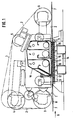
- FIG. 1 an elevational view is shown of a twin-wire section 1 of a paper machine, where the upper wire 2 runs over deflection rolls 3, 4, 5 and 6 and where the lower wire 7 runs substantially parallel to the upper wire and under the upper wire 2.
- the wires 2,7 define a wedge-shaped entrance portion 8, where the stock is successively compressed.
- Fig. 1 are also shown a multitude of set-up members, which are of a kind known in the art and which therefore are not more closely described.
- a dewatering run comprising a dewatering box 10 containing three chambers I, II and III, which carry different degrees of vacuum. Water from the stock is drawn up by ducts 11 into the chambers. The ducts 11 are included in the bottom 12 of the dewatering box 10. The upper wire 2 runs against this bottom.
- a supporting table 13 mounted fixedly relative to the dewatering box 10, this table being carried on a stand which has been generally denoted with reference numeral 14.
- a control member in the shape of a number of pressure elements 15 arranged to press the strips 16 upward in Fig.1 and thereby to apply pressure against the lower wire 7, and thereby against the stock.
- the strips 16 are provided with grooves 18 for carrying off water from the stock.
- each one of the pressure elements comprising at least two force-supplying members 19,20;21,22;23,24, between the respective strip 16,31,32 and the supporting table 13.
- the members 19-24 are disposed to displace the strips in the direction toward and away from the dewatering box 10.
- a first one of the members 19;21;23 is disposed to act against the forward end 25;26;27 of the respective strip 16,31,32 in the transport direction of the wires, and a second one of the members 20;22;24, to act against the rear end 28;29;30 of the strip in the transport direction of the wires.
- the force-supplying members 19-24 are individually controllable so that on one hand the pressure of the strip against the lower wire, and on the other hand the angle of the top surface of the strip with reference to the lower wire, can be adjusted.
- the strips 16,31,32 are placed parallelling each other, and spaced from each other.
- the distance between strips amounts only to a fraction of the width of one strip in the transport direction of the wires.
- the present invention therefore results in every strip being individually adjustable so that optimum control of the controlling track in the twin-wire section can be obtained.
- the force-supplying members comprise rubber bellows or equivalent, arranged to be controlled with the aid of compressed air.
- Fig. 2 a first embodiment of the invention, corresponding to the embodiment depicted in Fig. 1.
- the supporting table comprises a supporting heel 33, mounted on the carrying frame 34 of the supporting table 13.
- each one of the force-supplying members consists of a rubber bellows 19,20, where the two bellows 19,20, seen in section transversal to the longitudinal direction of the pressure element, are wedge-shaped and are placed against and upon each other so that together they constitute a substantially rectangular pillow between the strip 16 and the supporting table 13.
- the rubber bellows are preferably made of fabric-reinforced rubber, or of material having equivalent properties.
- a fixing element 37 in the shape of a plate.
- One marginal part 38 of the fixing element is integrally connected with the supporting table 13(33), and the other marginal part 39 of the fixing element is integrally connected with the strip 16.
- FIG. 3 the fixing which is on the left in Fig. 2 is shown on a larger scale.
- Fig. 3 is also shown the left margin of the lower bellows 20, fixed in place with a screwed joint to the supporting table.
- the reference numeral 40 indicates a clamp of plastic or metal and numeral 41, a screw.
- the fixing element may likewise be made of fabric-reinforced rubber, but it may also be made of sheet metal.
- interrupted lines schematically indicate nipples 42,42′ for introducing and carrying off compressed air to the bellows 19,20.
- the nipples are preferably placed on the respective end of the bellows.
- the surfaces of the bellows adjoining the underside surface of the strip 16 and the top surface of the supporting heel 33 have been affixed to the respective surface. This may be done with mechanical junctures or by cementing the bellows to the respective surface.
- the strip 31;32 respectively the supporting table 44;45, partly embrace each other so that the strip 31;32 has only limited mobility relative to the supporting table 44;45. Due to this embodiment there is no need for any fixing element of the type just described in connection with Fig. 2.
- a further bellows 46 has been provided which holds within itself the two bellows 21 and 22 already mentioned.
- These inner bellows 21,22 are fixed to the outer bellows 46, which in turn is preferentially affixed to the strip 31, respectively to the supporting table 44, by means of mechanical junctures or by cementing.
- a duct 47,48 serving introduction and evacuation of compressed air is provided to each inner bellows 21.22.
- the strip is restrictedly displaceable through a very short distance in the left/right direction in Fig. 4.
- the strip is further restrictedly displaceable upward/downward in Fig. 4, though through a longer distance than in the left/right direction.
- the free play which is present between the strip and the supporting table is merely conducive to easier upward/downward displacement and inclined positioning of the top surface of the strip.
- a duct 49 between the outer bellows and free atmosphere must be provided.
- the ends of the outer bellows may be open.
- Fig. 5 is shown an embodiment equivalent to that of Fig. 4, featuring two bellows 23,24 fixed in a carrying member 50,51, for the strip 32, and a portion 45 belonging to the supporting table.
- the strip is restrictedly displaceable relative to the supporting table.
- Ducts 52,53 have been provided for supplying and carrying off compressed air.
- the bellows 21,22,46,23,24 are preferably made of fabric-reinforced rubber material.
- the strips are made of some suitable, wear-resistant material.
- every rubber bellows 19 has a length consistent with the total length of the strips 16.
- one bellows or both bellows carrying a strip 16 may consist of two or more bellows 19′,19 ⁇ ,19′′′ located after each other in their longitudinal direction, so that the bellows 19′,19 ⁇ , 19′′′ in combination constitute a force-supplying member having a length consistent with the total length of the strips 16, see Fig. 7.
- every bellow 19′,19 ⁇ ,19′′′ is provided with a nipple for supplying and letting off compressed air.
- Each bellows 19′,19 ⁇ ,19′′′ is individually adjustable.
- This embodiment implies that it is even possible to control the pressure profile across the width of the wire 7.
- a long bellows extending over the entire width of the wire may be subdivided into different sections.
- the bellows may have other shapes and cover a greater or smaller part of the underside of the strips and of the top surface of the supporting table as seen in section according to Figs 2, 3 and 4. Futhermore, the bellows may be made of materials other than have been mentioned in the foregoing and which are suitable in the application in hand.
- the fixing element 37 may constitute a spring element in case it is made of metal.
Abstract
Description
- The present invention concerns a means for controlling wires in a paper machine or in a cardboard machine.
- More specifically, the means relates to the controlling of wires in a twin-wire section where the wires run parallel, one above the other, and where stock is introduced between said wires to be dewatered. There is usually a dewatering box above the upper wire, partial vacuum prevailing in said dewatering box in order to suck up water that has been expressed from the stock. Under the lower wire is provided a supporting table or equivalent, which is fixed relative to the dewatering box.
- It is desirable, and necessary, in machines of this kind to be able to change, on one hand, the thickness of the gap defined between the wires and, on the other hand, the configuration of said gap in the transport direction of the wires.
- To this purpose there are controlling members to urge the lower wire upwards in a direction against the upper wire, which in its turn lies against the dewatering box.
- It is thus understood that said controlling members act between the supporting table and the lower wire.
- In the Swedish Patent No. 8501985-9 and its German equivalent No. 3,406,217 a wire controlling track is disclosed wherein is provided a number of strips positioned closely side by side and extending over the wire width, said strips lying against the lower wire and the pressure of said strips against the lower wire being adjustable. The strips are displaceable towards the lower wire and away therefrom, but the angle of the top surfaces of said strips against the wire transport plane is not adjustable.
- The problem solution described in the Swedish Patent No. 8501985-9 is furthermore encumbered by the drawback that the strips lie close together. This has the effect that the strips act on each other through friction, and proper control is therefore impeded. This is emphasized through the fact that the strips tend to assume oblique position so that their top surfaces are not fully parallel to the transport plane of the wires, owing to friction against the lower wire. Moreover, liquid cannot escape downward in said means unless the strips are designed to have suction slits or equivalent.
- In the German Patent No. 3,153,305 another wire controlling track is disclosed wherein a number of mutually spaced strips are present, lying against the lower wire. These strips are individually regulated as regards their pressure against the lower wire, with the aid of a spring member. However, each strip is pivotally connected with the spring member coordinated with the particular strip, and therefore the position of the top surface of the strips relative to the horizontal plane cannot be adjusted. Thus, according to this patent, compensation of inclined position of the strips' top surfaces relative to the surface of the lower wire, owing to friction between the lower wire and the strips, is not feasible.
- Various problem solutions serving to adjust the pressure against the wire, and thereby against the stock, are thus known in the art.
- It has turned out that, in order to attain optimum functioning regarding dewatering of stock in a twin-wire section, it is essential that the pressure against the forward end of the strips, in the transport direction, and that against the rear end is separately adjustable.
- This enables any desired pressure profile to be set up over each strip. Furthermore, the inclined positioning mentioned above can be eliminated.
- The present invention teaches a means by the aid of which it becomes possible to achieve what has just been said.
- Futhermore, the construction of the means is simple and sturdy.
- It is thus understood that the present invention relates to a means for controlling wires in a twin-wire section in a paper or cardboard machine where the wires run one over the other, for dewatering stock that is present between the wires, where a dewatering box is provided on one side of the wires and where a number of strips disposed side by side are provided on the other side of the wires, said strips running across the transport direction of the wires and over the entire width of the wires and where the strips have been arranged to be pressed against the wire located nearest to the strips, with the aid of pressure elements, where the pressure elements are arranged to act between the strips and a supporting table or equivalent, said supporting table being fixedly mounted relative to said dewatering box and being characterized in that for each strip a separate pressure element is provided, where each one of the pressure elements comprises at least two force-supplying members provided between the respective strip and the supporting table, said members being arranged to displace the strip in the direction towards and away from said dewatering box, that a first one of the members has been arranged to act against the forward end of the strip in the transport direction of the wires and that a second one of the members has been arranged to act against the rear end of the strip in said transport direction, and in that the force-supplying members are individually controllable so that on one hand the pressure of the strip against the wire and on the other hand the angle against the wire of the top surface of the strip can be adjusted.
- The invention is more closely described in the following in connection with the attached drawings showing embodiment examples of the invention, wherein:-
- - Fig. 1 shows a sectional view of a twin-wire section for a paper machine where the present invention is applied.
- - Fig. 2 shows, on larger scale, one strip and ancillary control members according to the invention, in section conforming to the section in Fig. 1.
- - Fig. 3 shows on an even larger scale the portion of said control member which is on the left in Fig. 2.
- - Fig. 4 shows a first alternative embodiment of the control member, in section conforming to the section in Fig. 1.
- - Fig. 5 shows a second alternative embodiment of the control member, in section conforming to the section in Fig. 1.
- - Figs 6 and 7 show various embodiments of force-supplying members, the figures being schematic sections taken in a vertical plane corresponding to the section A-A in Fig. 1.
- In Fig. 1, an elevational view is shown of a twin-wire section 1 of a paper machine, where the
upper wire 2 runs over deflection rolls 3, 4, 5 and 6 and where thelower wire 7 runs substantially parallel to the upper wire and under theupper wire 2. Thewires - In the
transport direction 9, and after said wedge-shaped entrance portion 8, a dewatering run is provided, comprising a dewateringbox 10 containing three chambers I, II and III, which carry different degrees of vacuum. Water from the stock is drawn up byducts 11 into the chambers. Theducts 11 are included in thebottom 12 of the dewateringbox 10. Theupper wire 2 runs against this bottom. - Under the lower wire is provided a supporting table 13, mounted fixedly relative to the
dewatering box 10, this table being carried on a stand which has been generally denoted withreference numeral 14. - Upon the supporting table 13 is provided a control member in the shape of a number of
pressure elements 15 arranged to press thestrips 16 upward in Fig.1 and thereby to apply pressure against thelower wire 7, and thereby against the stock. - These
pressure elements 15, one of which is shown on a larger scale in Fig. 2, are thus placed between the underside of thestrips 16 and the supporting table 13. As has been mentioned, the top surfaces 17 of the strips have been disposed to lie against thelower wire 7. - The
strips 16 are provided withgrooves 18 for carrying off water from the stock. - According to the present invention, a
separate pressure element 15 has been provided for eachstrip 16, each one of the pressure elements comprising at least two force-supplyingmembers respective strip box 10. A first one of themembers 19;21;23 is disposed to act against theforward end 25;26;27 of therespective strip members 20;22;24, to act against therear end 28;29;30 of the strip in the transport direction of the wires. - Furthermore, the force-supplying members 19-24 are individually controllable so that on one hand the pressure of the strip against the lower wire, and on the other hand the angle of the top surface of the strip with reference to the lower wire, can be adjusted.
- According to a preferred embodiment, the
strips - This entails that the strips cannot affect each other by hooking onto each other or by lying tight together, which would be the case if the strips were placed very close to each other. If such interference were to occur, the individual adjustment of the strips would be impeded.
- It is thus obvious that the present invention completely solves the initially stated drawbacks embarrassing the means of prior art.
- The present invention therefore results in every strip being individually adjustable so that optimum control of the controlling track in the twin-wire section can be obtained.
- According to a specially preferred embodiment of the invention, the force-supplying members comprise rubber bellows or equivalent, arranged to be controlled with the aid of compressed air.
- In Fig. 2 is shown a first embodiment of the invention, corresponding to the embodiment depicted in Fig. 1.
- According to this embodiment, the supporting table comprises a supporting
heel 33, mounted on the carryingframe 34 of the supporting table 13. - According to the embodiment depicted in Fig. 2, each one of the force-supplying members consists of a
rubber bellows bellows strip 16 and the supporting table 13. - The rubber bellows are preferably made of fabric-reinforced rubber, or of material having equivalent properties.
- Between the
sides bellows fixing element 37 in the shape of a plate. Onemarginal part 38 of the fixing element is integrally connected with the supporting table 13(33), and the othermarginal part 39 of the fixing element is integrally connected with thestrip 16. - In Fig. 3, the fixing which is on the left in Fig. 2 is shown on a larger scale. In Fig. 3 is also shown the left margin of the
lower bellows 20, fixed in place with a screwed joint to the supporting table. Thereference numeral 40 indicates a clamp of plastic or metal andnumeral 41, a screw. - The fixing element may likewise be made of fabric-reinforced rubber, but it may also be made of sheet metal.
- In Fig. 2, interrupted lines schematically indicate
nipples bellows - It is obvious that if compressed air is introduced in the
bellows 19 up to pressure higher inbellows 19 than inbellows 20, the left end of thestrip 19, its forward end, will be raised more than its right-hand end, the rear end. This is illustrated by the interruptedline 43 in Fig. 2. - Suitably, the surfaces of the bellows adjoining the underside surface of the
strip 16 and the top surface of the supportingheel 33 have been affixed to the respective surface. This may be done with mechanical junctures or by cementing the bellows to the respective surface. - In Figs 4 and 5, other alternative preferred embodiments are shown.
- According to these embodiments, the
strip 31;32, respectively the supporting table 44;45, partly embrace each other so that thestrip 31;32 has only limited mobility relative to the supporting table 44;45. Due to this embodiment there is no need for any fixing element of the type just described in connection with Fig. 2. - According to the embodiment depicted in Fig. 4, a further bellows 46 has been provided which holds within itself the two bellows 21 and 22 already mentioned. These inner bellows 21,22 are fixed to the outer bellows 46, which in turn is preferentially affixed to the
strip 31, respectively to the supporting table 44, by means of mechanical junctures or by cementing. - A
duct - As can be seen in Fig. 4, the strip is restrictedly displaceable through a very short distance in the left/right direction in Fig. 4. The strip is further restrictedly displaceable upward/downward in Fig. 4, though through a longer distance than in the left/right direction. Actually, there is no desire to make the strip displaceable in the left/right direction: the free play which is present between the strip and the supporting table is merely conducive to easier upward/downward displacement and inclined positioning of the top surface of the strip.
- A
duct 49 between the outer bellows and free atmosphere must be provided. As an alternative, the ends of the outer bellows may be open. - In Fig. 5 is shown an embodiment equivalent to that of Fig. 4, featuring two bellows 23,24 fixed in a carrying
member strip 32, and aportion 45 belonging to the supporting table. - According to this embodiment, too, the strip is restrictedly displaceable relative to the supporting table.
Ducts - According to the embodiments described in connection with Figs 4 and 5 as well, the
bellows - The strips are made of some suitable, wear-resistant material.
- According to the embodiments, shown in Fig. 6, every rubber bellows 19 has a length consistent with the total length of the
strips 16. However, according to another embodiment one bellows or both bellows carrying astrip 16 may consist of two or more bellows 19′,19˝,19‴ located after each other in their longitudinal direction, so that thebellows 19′,19˝, 19‴ in combination constitute a force-supplying member having a length consistent with the total length of thestrips 16, see Fig. 7. In that case, everybellow 19′,19˝,19‴ is provided with a nipple for supplying and letting off compressed air. Each bellows 19′,19˝,19‴ is individually adjustable. - This embodiment implies that it is even possible to control the pressure profile across the width of the
wire 7. - According to a further alternative embodiment, a long bellows extending over the entire width of the wire may be subdivided into different sections.
- In the foregoing various exemplifying embodiments have been described.
- It is obvious that the bellows may have other shapes and cover a greater or smaller part of the underside of the strips and of the top surface of the supporting table as seen in section according to Figs 2, 3 and 4. Futhermore, the bellows may be made of materials other than have been mentioned in the foregoing and which are suitable in the application in hand.
- It goes without saying that the strips may be given other embodiments, as may also the supporting table.
- Furthermore, the fixing
element 37 may constitute a spring element in case it is made of metal. - Thus and therefore it is obvious that the present invention shall not be considered confined to the embodiments presented in the foregoing, and that it may rather be varied within its frame as stated by the claims following below.
Claims (8)
Priority Applications (1)
| Application Number | Priority Date | Filing Date | Title |
|---|---|---|---|
| AT88113618T ATE66027T1 (en) | 1987-09-07 | 1988-08-22 | DEVICE FOR CHECKING THE STRAINERS IN A PAPER OR BOARD MACHINE. |
Applications Claiming Priority (2)
| Application Number | Priority Date | Filing Date | Title |
|---|---|---|---|
| SE8703468 | 1987-09-07 | ||
| SE8703468A SE456590B (en) | 1987-09-07 | 1987-09-07 | DEVICE FOR CONTROL OF VIRUSES IN A PAPER MACHINE OR CARTON MACHINE |
Publications (2)
| Publication Number | Publication Date |
|---|---|
| EP0306759A1 true EP0306759A1 (en) | 1989-03-15 |
| EP0306759B1 EP0306759B1 (en) | 1991-08-07 |
Family
ID=20369499
Family Applications (1)
| Application Number | Title | Priority Date | Filing Date |
|---|---|---|---|
| EP88113618A Expired - Lifetime EP0306759B1 (en) | 1987-09-07 | 1988-08-22 | Means for controlling wires in a paper machine or cardboard machine |
Country Status (13)
| Country | Link |
|---|---|
| EP (1) | EP0306759B1 (en) |
| JP (1) | JP2691913B2 (en) |
| KR (1) | KR970008599B1 (en) |
| AT (1) | ATE66027T1 (en) |
| AU (1) | AU2303188A (en) |
| BR (1) | BR8807192A (en) |
| CA (1) | CA1335632C (en) |
| CH (1) | CH676257A5 (en) |
| DE (1) | DE3864105D1 (en) |
| ES (1) | ES2025747T3 (en) |
| FI (1) | FI90572C (en) |
| SE (1) | SE456590B (en) |
| WO (1) | WO1989002499A1 (en) |
Cited By (10)
| Publication number | Priority date | Publication date | Assignee | Title |
|---|---|---|---|---|
| EP0372815A2 (en) * | 1988-12-01 | 1990-06-13 | Valmet-Karhula Inc. | Apparatus for guiding wires of a paper machine former |
| WO1991010775A1 (en) * | 1988-07-15 | 1991-07-25 | J.M. Voith Gmbh | Device for guiding the screen of a double-screen part of a paper- or cardboard-making machine |
| EP0438685A1 (en) * | 1990-01-26 | 1991-07-31 | Sulzer-Escher Wyss Gmbh | Former in a paper machine |
| EP0454989A1 (en) * | 1990-05-04 | 1991-11-06 | Voith Sulzer Papiermaschinen GmbH | Vertical former |
| EP0503249A1 (en) * | 1991-03-09 | 1992-09-16 | Voith Sulzer Papiermaschinen GmbH | Dewatering apparatus for the wet section of a papermachine |
| EP0629740A1 (en) * | 1993-06-17 | 1994-12-21 | Valmet Paper Machinery Inc. | Method and device and arrangement of regulation in a paper machine in the control of the transverse profile of the paper web |
| US5389206A (en) * | 1989-08-22 | 1995-02-14 | J. M. Voith Gmbh | Twin wire former |
| US5395484A (en) * | 1992-01-17 | 1995-03-07 | Valmet Paper Machinery Inc. | Twin wire web former for a paper machine |
| DE10333201A1 (en) * | 2003-07-22 | 2005-02-24 | Voith Paper Patent Gmbh | Papermaking dewatering double sieve belt passes over transverse pressure beam subdivided into equal segments with individual pressure control |
| AT14760U1 (en) * | 2014-07-15 | 2016-05-15 | Valmet Technologies Inc | Loading device for a machine for producing fiber webs |
Families Citing this family (8)
| Publication number | Priority date | Publication date | Assignee | Title |
|---|---|---|---|---|
| DE3929265C2 (en) * | 1989-09-02 | 1997-05-07 | Voith Sulzer Papiermasch Gmbh | Strip for sheet formation zone of a paper machine |
| DE4026953C2 (en) * | 1990-01-26 | 1995-11-30 | Escher Wyss Gmbh | Dewatering device and method for dewatering on a twin wire former |
| DE4005420C2 (en) * | 1990-02-21 | 1995-06-08 | Voith Gmbh J M | Twin wire former |
| DE4009628C2 (en) * | 1990-03-26 | 1994-11-03 | Voith Gmbh J M | Pressure medium support device |
| DE4019884A1 (en) * | 1990-06-22 | 1992-01-09 | Voith Gmbh J M | PERFORMANCE SUPPLY SUPPORT FOR A SCREENING BELT |
| FI96623C (en) | 1994-08-31 | 1996-07-25 | Valmet Paper Machinery Inc | Double-wire molders, especially for fast paper machines |
| DE29504419U1 (en) * | 1995-03-15 | 1995-05-11 | Voith Sulzer Papiermasch Gmbh | Last unit for the flexible support of a paper machine belt |
| JP6199136B2 (en) * | 2013-09-17 | 2017-09-20 | 三菱重工業株式会社 | Liquid solid matter take-out apparatus and liquid solid matter take-out method |
Citations (4)
| Publication number | Priority date | Publication date | Assignee | Title |
|---|---|---|---|---|
| US3027940A (en) * | 1958-12-31 | 1962-04-03 | Lodding Engineering Corp | Adjustable supports for fourdrinier screen wires |
| FR2131746A5 (en) * | 1971-03-31 | 1972-11-10 | Black Clawson Co | |
| GB2174120A (en) * | 1985-04-26 | 1986-10-29 | Doerries Gmbh | Twin wire guiding apparatus |
| WO1987006633A1 (en) * | 1986-04-30 | 1987-11-05 | Viljo Klemetti | Method for regulating the cross-direction profile of a paper web and equipment for the application of the method |
Family Cites Families (3)
| Publication number | Priority date | Publication date | Assignee | Title |
|---|---|---|---|---|
| US3357881A (en) * | 1964-10-15 | 1967-12-12 | Fitchburg Paper | Wire support for papermaking machines |
| DE3406217C1 (en) * | 1984-02-21 | 1985-10-31 | O. Dörries GmbH, 5160 Düren | Apparatus for guiding the wire screens of a twin wire set of a paper making or board making machine |
| DE3503242A1 (en) * | 1985-01-31 | 1986-08-07 | O. Dörries GmbH, 5160 Düren | Device for guiding the wires of a twin-wire section of a paper- or cardboard-machine |
-
1987
- 1987-09-07 SE SE8703468A patent/SE456590B/en unknown
-
1988
- 1988-08-22 DE DE8888113618T patent/DE3864105D1/en not_active Expired - Fee Related
- 1988-08-22 ES ES198888113618T patent/ES2025747T3/en not_active Expired - Lifetime
- 1988-08-22 EP EP88113618A patent/EP0306759B1/en not_active Expired - Lifetime
- 1988-08-22 AT AT88113618T patent/ATE66027T1/en not_active IP Right Cessation
- 1988-09-06 CA CA000576547A patent/CA1335632C/en not_active Expired - Fee Related
- 1988-09-06 FI FI884109A patent/FI90572C/en not_active IP Right Cessation
- 1988-09-06 CH CH1579/89A patent/CH676257A5/de not_active IP Right Cessation
- 1988-09-06 BR BR888807192A patent/BR8807192A/en unknown
- 1988-09-06 WO PCT/FI1988/000142 patent/WO1989002499A1/en unknown
- 1988-09-06 AU AU23031/88A patent/AU2303188A/en not_active Abandoned
- 1988-09-07 KR KR1019880011537A patent/KR970008599B1/en not_active IP Right Cessation
- 1988-09-07 JP JP63224367A patent/JP2691913B2/en not_active Expired - Lifetime
Patent Citations (4)
| Publication number | Priority date | Publication date | Assignee | Title |
|---|---|---|---|---|
| US3027940A (en) * | 1958-12-31 | 1962-04-03 | Lodding Engineering Corp | Adjustable supports for fourdrinier screen wires |
| FR2131746A5 (en) * | 1971-03-31 | 1972-11-10 | Black Clawson Co | |
| GB2174120A (en) * | 1985-04-26 | 1986-10-29 | Doerries Gmbh | Twin wire guiding apparatus |
| WO1987006633A1 (en) * | 1986-04-30 | 1987-11-05 | Viljo Klemetti | Method for regulating the cross-direction profile of a paper web and equipment for the application of the method |
Cited By (18)
| Publication number | Priority date | Publication date | Assignee | Title |
|---|---|---|---|---|
| WO1991010775A1 (en) * | 1988-07-15 | 1991-07-25 | J.M. Voith Gmbh | Device for guiding the screen of a double-screen part of a paper- or cardboard-making machine |
| EP0372815A3 (en) * | 1988-12-01 | 1990-07-18 | Valmet-Karhula Inc. | Apparatus for guiding wires of a paper machine former |
| EP0372815A2 (en) * | 1988-12-01 | 1990-06-13 | Valmet-Karhula Inc. | Apparatus for guiding wires of a paper machine former |
| US5389206A (en) * | 1989-08-22 | 1995-02-14 | J. M. Voith Gmbh | Twin wire former |
| US5853544A (en) * | 1989-08-22 | 1998-12-29 | J.M. Voith Gmbh | Twin wire former |
| US5718805A (en) * | 1989-08-22 | 1998-02-17 | J. M. Voith Gmbh | Twin wire former |
| US5500091A (en) * | 1989-08-22 | 1996-03-19 | J. M. Voith Gmbh | Twin-wire former |
| EP0438685A1 (en) * | 1990-01-26 | 1991-07-31 | Sulzer-Escher Wyss Gmbh | Former in a paper machine |
| EP0454989A1 (en) * | 1990-05-04 | 1991-11-06 | Voith Sulzer Papiermaschinen GmbH | Vertical former |
| US5262010A (en) * | 1991-03-09 | 1993-11-16 | Sulzer Escher Wyss Gmbh | Dewatering device with adjustable force elements for the web-forming section of a papermaking machine |
| EP0503249A1 (en) * | 1991-03-09 | 1992-09-16 | Voith Sulzer Papiermaschinen GmbH | Dewatering apparatus for the wet section of a papermachine |
| US5395484A (en) * | 1992-01-17 | 1995-03-07 | Valmet Paper Machinery Inc. | Twin wire web former for a paper machine |
| US5536372A (en) * | 1992-01-17 | 1996-07-16 | Valmet Corporation | Web former for a paper machine with spring blade loading device |
| US5582687A (en) * | 1992-01-17 | 1996-12-10 | Valmet Corporation | Web former for a paper machine |
| EP0629740A1 (en) * | 1993-06-17 | 1994-12-21 | Valmet Paper Machinery Inc. | Method and device and arrangement of regulation in a paper machine in the control of the transverse profile of the paper web |
| US5552021A (en) * | 1993-06-17 | 1996-09-03 | Valmet Corporation | Method, device and arrangement for regulating the control of a transverse profile of a paper web in a paper machine |
| DE10333201A1 (en) * | 2003-07-22 | 2005-02-24 | Voith Paper Patent Gmbh | Papermaking dewatering double sieve belt passes over transverse pressure beam subdivided into equal segments with individual pressure control |
| AT14760U1 (en) * | 2014-07-15 | 2016-05-15 | Valmet Technologies Inc | Loading device for a machine for producing fiber webs |
Also Published As
| Publication number | Publication date |
|---|---|
| KR890005347A (en) | 1989-05-13 |
| JPH01104895A (en) | 1989-04-21 |
| KR970008599B1 (en) | 1997-05-27 |
| FI884109A0 (en) | 1988-09-06 |
| WO1989002499A1 (en) | 1989-03-23 |
| SE456590B (en) | 1988-10-17 |
| CH676257A5 (en) | 1990-12-28 |
| CA1335632C (en) | 1995-05-23 |
| EP0306759B1 (en) | 1991-08-07 |
| ATE66027T1 (en) | 1991-08-15 |
| ES2025747T3 (en) | 1992-04-01 |
| DE3864105D1 (en) | 1991-09-12 |
| FI90572C (en) | 1994-02-25 |
| AU2303188A (en) | 1989-04-17 |
| FI90572B (en) | 1993-11-15 |
| FI884109A (en) | 1989-03-08 |
| JP2691913B2 (en) | 1997-12-17 |
| SE8703468D0 (en) | 1987-09-07 |
| BR8807192A (en) | 1989-10-17 |
Similar Documents
| Publication | Publication Date | Title |
|---|---|---|
| EP0306759B1 (en) | Means for controlling wires in a paper machine or cardboard machine | |
| US5185064A (en) | Means for controlling wires in a paper machine or cardboard machine | |
| JPH0364636B2 (en) | ||
| US5706994A (en) | Vacuum assisted web drive for corrugator double backer | |
| US5320713A (en) | Method of using a forming section of a papermaking machine | |
| US4818330A (en) | One-sided corrugated board machine having replacable corrugating rollers | |
| US4738744A (en) | One-sided corrugated board machine | |
| KR19990013965A (en) | Vacuum web driver for corrugated double backers | |
| GB2125839A (en) | Dewatering apparatus | |
| JP3059673B2 (en) | Rib for paper machine dehydrator | |
| FI95058B (en) | Paper machine dewatering device list | |
| FI104192B (en) | Zone adjustable load box for the shapes of a paper or cardboard machine | |
| CA2050647A1 (en) | Auto-slice, especially for a twin wire former | |
| US1936609A (en) | Paper making apparatus | |
| WO1998044193A1 (en) | Apparatus for removing fluid from a fibrous web | |
| KR910002617Y1 (en) | Support apparatus for a dewatering unit in the web-forming section of a paper machine | |
| US4544448A (en) | Filter press | |
| GB2071723A (en) | Doctor blade mounting assembly | |
| EP0940246A2 (en) | Vacuum assisted beltless holddown for double backer | |
| JP2844904B2 (en) | Twin wire equipment for papermaking machines |
Legal Events
| Date | Code | Title | Description |
|---|---|---|---|
| PUAI | Public reference made under article 153(3) epc to a published international application that has entered the european phase |
Free format text: ORIGINAL CODE: 0009012 |
|
| AK | Designated contracting states |
Kind code of ref document: A1 Designated state(s): AT DE ES FR GB IT |
|
| 17P | Request for examination filed |
Effective date: 19890823 |
|
| 17Q | First examination report despatched |
Effective date: 19891106 |
|
| GRAA | (expected) grant |
Free format text: ORIGINAL CODE: 0009210 |
|
| AK | Designated contracting states |
Kind code of ref document: B1 Designated state(s): AT DE ES FR GB IT |
|
| REF | Corresponds to: |
Ref document number: 66027 Country of ref document: AT Date of ref document: 19910815 Kind code of ref document: T |
|
| PGFP | Annual fee paid to national office [announced via postgrant information from national office to epo] |
Ref country code: ES Payment date: 19910830 Year of fee payment: 4 |
|
| REF | Corresponds to: |
Ref document number: 3864105 Country of ref document: DE Date of ref document: 19910912 |
|
| ITF | It: translation for a ep patent filed |
Owner name: STUDIO CONS. BREVETTUALE S.R.L. |
|
| ET | Fr: translation filed | ||
| REG | Reference to a national code |
Ref country code: ES Ref legal event code: FG2A Ref document number: 2025747 Country of ref document: ES Kind code of ref document: T3 |
|
| PLBE | No opposition filed within time limit |
Free format text: ORIGINAL CODE: 0009261 |
|
| STAA | Information on the status of an ep patent application or granted ep patent |
Free format text: STATUS: NO OPPOSITION FILED WITHIN TIME LIMIT |
|
| 26N | No opposition filed | ||
| PG25 | Lapsed in a contracting state [announced via postgrant information from national office to epo] |
Ref country code: ES Free format text: LAPSE BECAUSE OF THE APPLICANT RENOUNCES Effective date: 19920824 |
|
| PGFP | Annual fee paid to national office [announced via postgrant information from national office to epo] |
Ref country code: FR Payment date: 19970717 Year of fee payment: 10 |
|
| PGFP | Annual fee paid to national office [announced via postgrant information from national office to epo] |
Ref country code: GB Payment date: 19970813 Year of fee payment: 10 |
|
| PG25 | Lapsed in a contracting state [announced via postgrant information from national office to epo] |
Ref country code: GB Free format text: LAPSE BECAUSE OF NON-PAYMENT OF DUE FEES Effective date: 19980822 |
|
| GBPC | Gb: european patent ceased through non-payment of renewal fee |
Effective date: 19980822 |
|
| PG25 | Lapsed in a contracting state [announced via postgrant information from national office to epo] |
Ref country code: FR Free format text: LAPSE BECAUSE OF NON-PAYMENT OF DUE FEES Effective date: 19990430 |
|
| REG | Reference to a national code |
Ref country code: FR Ref legal event code: ST |
|
| REG | Reference to a national code |
Ref country code: ES Ref legal event code: FD2A Effective date: 19991007 |
|
| PGFP | Annual fee paid to national office [announced via postgrant information from national office to epo] |
Ref country code: AT Payment date: 20010828 Year of fee payment: 14 |
|
| PGFP | Annual fee paid to national office [announced via postgrant information from national office to epo] |
Ref country code: DE Payment date: 20010905 Year of fee payment: 14 |
|
| PG25 | Lapsed in a contracting state [announced via postgrant information from national office to epo] |
Ref country code: AT Free format text: LAPSE BECAUSE OF NON-PAYMENT OF DUE FEES Effective date: 20020822 |
|
| PG25 | Lapsed in a contracting state [announced via postgrant information from national office to epo] |
Ref country code: DE Free format text: LAPSE BECAUSE OF NON-PAYMENT OF DUE FEES Effective date: 20030301 |
|
| PG25 | Lapsed in a contracting state [announced via postgrant information from national office to epo] |
Ref country code: IT Free format text: LAPSE BECAUSE OF NON-PAYMENT OF DUE FEES Effective date: 20050822 |