KR910009249B1 - Magnetron cathodes for the sputtering of ferromagnetic targets - Google Patents
Magnetron cathodes for the sputtering of ferromagnetic targets Download PDFInfo
- Publication number
- KR910009249B1 KR910009249B1 KR1019840007652A KR840007652A KR910009249B1 KR 910009249 B1 KR910009249 B1 KR 910009249B1 KR 1019840007652 A KR1019840007652 A KR 1019840007652A KR 840007652 A KR840007652 A KR 840007652A KR 910009249 B1 KR910009249 B1 KR 910009249B1
- Authority
- KR
- South Korea
- Prior art keywords
- pole
- magnet
- sputtering
- pole plate
- plate
- Prior art date
Links
- 238000004544 sputter deposition Methods 0.000 title claims description 68
- 230000005294 ferromagnetic effect Effects 0.000 title claims 2
- 230000005291 magnetic effect Effects 0.000 claims description 76
- 239000000463 material Substances 0.000 claims description 49
- CWYNVVGOOAEACU-UHFFFAOYSA-N Fe2+ Chemical compound [Fe+2] CWYNVVGOOAEACU-UHFFFAOYSA-N 0.000 claims description 42
- 229910052751 metal Inorganic materials 0.000 claims description 27
- 239000002184 metal Substances 0.000 claims description 27
- 239000002826 coolant Substances 0.000 claims description 7
- 239000000758 substrate Substances 0.000 claims description 2
- SZVJSHCCFOBDDC-UHFFFAOYSA-N iron(II,III) oxide Inorganic materials O=[Fe]O[Fe]O[Fe]=O SZVJSHCCFOBDDC-UHFFFAOYSA-N 0.000 claims 1
- 239000000696 magnetic material Substances 0.000 description 9
- 238000000034 method Methods 0.000 description 9
- 230000008569 process Effects 0.000 description 8
- 230000003628 erosive effect Effects 0.000 description 6
- 230000005415 magnetization Effects 0.000 description 5
- XKRFYHLGVUSROY-UHFFFAOYSA-N Argon Chemical compound [Ar] XKRFYHLGVUSROY-UHFFFAOYSA-N 0.000 description 4
- 230000009471 action Effects 0.000 description 4
- 238000000576 coating method Methods 0.000 description 4
- 230000000694 effects Effects 0.000 description 4
- 239000012212 insulator Substances 0.000 description 4
- RYGMFSIKBFXOCR-UHFFFAOYSA-N Copper Chemical compound [Cu] RYGMFSIKBFXOCR-UHFFFAOYSA-N 0.000 description 3
- 229910052802 copper Inorganic materials 0.000 description 3
- 239000010949 copper Substances 0.000 description 3
- BGPVFRJUHWVFKM-UHFFFAOYSA-N N1=C2C=CC=CC2=[N+]([O-])C1(CC1)CCC21N=C1C=CC=CC1=[N+]2[O-] Chemical compound N1=C2C=CC=CC2=[N+]([O-])C1(CC1)CCC21N=C1C=CC=CC1=[N+]2[O-] BGPVFRJUHWVFKM-UHFFFAOYSA-N 0.000 description 2
- 229910052786 argon Inorganic materials 0.000 description 2
- 150000001768 cations Chemical class 0.000 description 2
- 239000011248 coating agent Substances 0.000 description 2
- 238000001816 cooling Methods 0.000 description 2
- 238000010586 diagram Methods 0.000 description 2
- 239000007789 gas Substances 0.000 description 2
- 239000011810 insulating material Substances 0.000 description 2
- 238000009413 insulation Methods 0.000 description 2
- 238000005461 lubrication Methods 0.000 description 2
- 238000004519 manufacturing process Methods 0.000 description 2
- 229920006395 saturated elastomer Polymers 0.000 description 2
- 241000283153 Cetacea Species 0.000 description 1
- XEEYBQQBJWHFJM-UHFFFAOYSA-N Iron Chemical group [Fe] XEEYBQQBJWHFJM-UHFFFAOYSA-N 0.000 description 1
- 229910000831 Steel Inorganic materials 0.000 description 1
- 239000000654 additive Substances 0.000 description 1
- 229910052782 aluminium Inorganic materials 0.000 description 1
- XAGFODPZIPBFFR-UHFFFAOYSA-N aluminium Chemical compound [Al] XAGFODPZIPBFFR-UHFFFAOYSA-N 0.000 description 1
- 238000013459 approach Methods 0.000 description 1
- 230000008901 benefit Effects 0.000 description 1
- 230000015572 biosynthetic process Effects 0.000 description 1
- 230000008859 change Effects 0.000 description 1
- 230000008878 coupling Effects 0.000 description 1
- 238000010168 coupling process Methods 0.000 description 1
- 238000005859 coupling reaction Methods 0.000 description 1
- 230000001627 detrimental effect Effects 0.000 description 1
- 238000009826 distribution Methods 0.000 description 1
- 238000005553 drilling Methods 0.000 description 1
- 230000005611 electricity Effects 0.000 description 1
- 239000011521 glass Substances 0.000 description 1
- 238000010438 heat treatment Methods 0.000 description 1
- 238000005259 measurement Methods 0.000 description 1
- 230000004048 modification Effects 0.000 description 1
- 238000012986 modification Methods 0.000 description 1
- 230000003204 osmotic effect Effects 0.000 description 1
- 238000012856 packing Methods 0.000 description 1
- 230000000149 penetrating effect Effects 0.000 description 1
- 230000002093 peripheral effect Effects 0.000 description 1
- 239000002244 precipitate Substances 0.000 description 1
- 230000009467 reduction Effects 0.000 description 1
- 238000004062 sedimentation Methods 0.000 description 1
- 238000000926 separation method Methods 0.000 description 1
- 238000010008 shearing Methods 0.000 description 1
- 239000007787 solid Substances 0.000 description 1
- 239000007921 spray Substances 0.000 description 1
- 239000010959 steel Substances 0.000 description 1
- 230000000638 stimulation Effects 0.000 description 1
- 239000000126 substance Substances 0.000 description 1
- 230000000007 visual effect Effects 0.000 description 1
Images


Classifications
-
- H—ELECTRICITY
- H01—ELECTRIC ELEMENTS
- H01J—ELECTRIC DISCHARGE TUBES OR DISCHARGE LAMPS
- H01J37/00—Discharge tubes with provision for introducing objects or material to be exposed to the discharge, e.g. for the purpose of examination or processing thereof
- H01J37/32—Gas-filled discharge tubes
- H01J37/34—Gas-filled discharge tubes operating with cathodic sputtering
- H01J37/3411—Constructional aspects of the reactor
- H01J37/3441—Dark space shields
-
- H—ELECTRICITY
- H01—ELECTRIC ELEMENTS
- H01J—ELECTRIC DISCHARGE TUBES OR DISCHARGE LAMPS
- H01J37/00—Discharge tubes with provision for introducing objects or material to be exposed to the discharge, e.g. for the purpose of examination or processing thereof
- H01J37/32—Gas-filled discharge tubes
- H01J37/34—Gas-filled discharge tubes operating with cathodic sputtering
- H01J37/3402—Gas-filled discharge tubes operating with cathodic sputtering using supplementary magnetic fields
- H01J37/3405—Magnetron sputtering
- H01J37/3408—Planar magnetron sputtering
-
- H—ELECTRICITY
- H01—ELECTRIC ELEMENTS
- H01J—ELECTRIC DISCHARGE TUBES OR DISCHARGE LAMPS
- H01J37/00—Discharge tubes with provision for introducing objects or material to be exposed to the discharge, e.g. for the purpose of examination or processing thereof
- H01J37/32—Gas-filled discharge tubes
- H01J37/34—Gas-filled discharge tubes operating with cathodic sputtering
- H01J37/3411—Constructional aspects of the reactor
- H01J37/3414—Targets
- H01J37/3426—Material
-
- H—ELECTRICITY
- H01—ELECTRIC ELEMENTS
- H01J—ELECTRIC DISCHARGE TUBES OR DISCHARGE LAMPS
- H01J37/00—Discharge tubes with provision for introducing objects or material to be exposed to the discharge, e.g. for the purpose of examination or processing thereof
- H01J37/32—Gas-filled discharge tubes
- H01J37/34—Gas-filled discharge tubes operating with cathodic sputtering
- H01J37/3488—Constructional details of particle beam apparatus not otherwise provided for, e.g. arrangement, mounting, housing, environment; special provisions for cleaning or maintenance of the apparatus
- H01J37/3497—Temperature of target
Landscapes
- Physics & Mathematics (AREA)
- Engineering & Computer Science (AREA)
- Plasma & Fusion (AREA)
- Chemical & Material Sciences (AREA)
- Analytical Chemistry (AREA)
- Physical Vapour Deposition (AREA)
- Thin Magnetic Films (AREA)
Abstract
내용 없음.No content.
Description
제1도는 본 발명의 자전관의 주요 부분들을 도식적으로 나타낸 측단면도.1 is a side cross-sectional view schematically showing the main parts of the magnetron of the present invention.
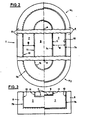
제2도 및 제3도는 본 발명의 자전관의 다양한 형태와 그 변형 가능성에 대한 예시도.2 and 3 illustrate various forms of the magnetron of the present invention and the possibility of modification thereof.
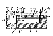
제4도는 제1도와 유사한 하나의 축단면을 나타내지만, 여기에 다른 구성부분을 추가한 특수한 실시사례의 예시도.4 shows one axial cross section similar to that of FIG. 1, but illustrates an exemplary embodiment in which another component is added thereto.
제5도는 본 발명의 자전관을 변형시킨 제1도의 좌측 절반부와 유사한 도식적인 축 단면도이고, 이 변형체에서는 자극들과 극편들이 외부로 에워싸고 있다.FIG. 5 is a schematic axial sectional view similar to the left half of FIG. 1 in which the magnetron of the present invention is modified, in which the magnetic poles and pole pieces are enclosed to the outside.
제6도는 제5도와 유사한 도식적인 축단면도이고, 마이너스(-)겹침″d″를 같이 나타내고 있음.FIG. 6 is a schematic axial cross-sectional view similar to FIG. 5, with minus overlap ″ d ″.
제7도는 제6도와 유사한 도식적인 축단면도이고, 영구자석의 역 배치를 같이 나타내고 있음.FIG. 7 is a schematic axial cross-sectional view similar to FIG. 6, showing the reverse arrangement of permanent magnets.
제8도는 제4도에 의한 자전관을 변형시킨 축 단면도이고, 자전관에서는 극판과 자석 시스템 사이에 열전도성 금속체가 편편한 금속판으로 완성되어 있다.8 is a cross-sectional view of a shaft in which the magnetron tube according to FIG. 4 is deformed, and the magnetron tube is made of a metal plate having a flat thermal conductive metal body between the pole plate and the magnet system.
제9도는 도표와 함께, 제8도 좌측 절반부의 한 부분의 확대 단면도이고, 도표에는 극편 표면위 2mm의 간격에서 생기는 자장강도의 수평분력(Hx)이 도시되어 있으며, 또한 자전관을 방사상으로 측정한 것이 부가되어 있음.FIG. 9 is an enlarged cross-sectional view of a portion of the left half of FIG. 8, along with a diagram. The diagram shows the horizontal component (Hx) of the magnetic field strength occurring at an interval of 2 mm on the pole surface. Is added.
제10도는 제9도 유사한 도면을 나타내고 있지만 ″침식측면(=짧은 줄로 그어진 선)이 도시되어 있음.FIG. 10 shows a similar view to FIG. 9 but shows the erosion side (= short line).
제11도는 제8도에 따른 자전관 작동의 특성곡선을 나타냄.FIG. 11 shows the characteristic curve of magnetron operation according to FIG.
* 도면의 주요부분에 대한 부호의 설명* Explanation of symbols for the main parts of the drawings
1 : 기재 2 : 자석시스템1: Base material 2: Magnet system
3a, 4a : 자극 5 : 계철3a, 4a: stimulation 5: yoke
7 : 극판 7a : 스퍼어터링면7:
7b, 7c : 단부측면 8, 9 : 극편7b, 7c:
10, 11 : 이탈면 12, 13 : 흡기슬리트10, 11:
16 : 금속체 17 : 냉각제관16 metal body 17 coolant pipe
34, 35 : 자석체34, 35: magnet body
본 발명의 제1철 자석의 극판(極板)을 스퍼어터링하기 위한 자전관 음극에 관한 것으로, 계철을 가진 자석시스템이 있는 음극의 기재로 구성되며, 마주보고 있는 양국의, 주변에 연결되고 서로 뒤섞여 위치한 자극들에 위치하며, 최소한 부분적으로는 극판물질로 구성되는 자극들의 극편들은, 자극들의 진행에 따라, 유사한 이탈면에 병렬되어 있다. 그 이면에는 선회하는 두 개의 흡기 슬리트를 그대로 둔 채 배치의 심층방향으로, 제1철 자석 금속으로 구성되고 주변에 연결되어 있는 극판이 스퍼어터링면과 함께 배열되며, 자극들과 극판은 전기가 통하는 상태에서 연결되어 있다. 편편하거나 둥글게 만 곡된 스퍼어터링면에 대한 이러한 상대적 위치에서의 영구자석 또는 전기자석의 공간적으로 제한된 배치는 다음의 사실로 고려된다. 즉, 자력선에 의한 고리모양의 폐쇄된 통로가 스퍼어터링면위에 생기고, 스퍼어터링 과정에 작용을 미치는 미광의 방출은 통로 때문에 스퍼어터링면에 직접적으로 가까운 곳에 한정되며, 그 때문에 스퍼어터링율은 10% 이상 증가된다. 미광방출의 밖에 놓여진 효과적인 극판 상부면은 ″스퍼어터링면″으로 표시되며, 그 면으로부터 스퍼어터링된 미립자들, 그러니까 일반적으로 극판전면이 나온다.(DE-AS 24 31 832)The present invention relates to a magnetron cathode for sputtering a pole plate of a ferrous magnet of the present invention, comprising a base of a cathode having a magnet system with yoke, and connected to each other and to each other, facing each other. The pole pieces of the poles, which are located in interlaced poles, at least partly composed of the plate material, are parallel to the plane of similar departure as the poles progress. Behind it, in the deep direction of the arrangement, leaving the two intake slits that pivot, the pole plates made of ferrous magnet metal and connected to the periphery are arranged with the sputtering surface, and the poles and pole plates are electrically Is connected while The spatially constrained placement of permanent or electromagnets in this relative position with respect to flat or rounded sputtering surfaces is considered to be the following fact. That is, a ring-shaped closed passage caused by the magnetic lines of force is generated on the sputtering surface, and the emission of stray light acting on the sputtering process is limited to a position directly near the sputtering surface because of the passage, and therefore sputtering The rate is increased by more than 10%. The effective top surface of the plate placed outside the stray light is marked as ″ sputtering surface ″, from which the sputtered particulates, usually the front of the plate, emerge (DE-AS 24 31 832).
이와 같은 자전관 음극은 한정된 이용가능성을 가지고 있거나 주어진 기대치를 완전히 충족시키지 못하는 많은 변형체에서 알려져 있다. 그래서 잘 알려진 완성형태에서, 자석 시스템의 극면은 극판 뒤에 배치된다. 그 결과 다수의 자정선이 극판의 평면을 두 번 뚫고 지나가게 된다. 그러나 이런 제작방식은, 예컨대 자성을 띤 기록테이프를 생산하는데 필요한, 자석재료로 만들어진 극판에는 사용될 수 없거나, 부가적인 조치가 취해지는 경우에만 사용될 수 있다.Such magnetron cathodes are known in many variants that have limited availability or do not fully meet given expectations. So in a well known form, the pole face of the magnet system is placed behind the pole plate. As a result, a number of midlines pass through the plane of the plate twice. However, this manufacturing method can not be used for the electrode plate made of magnetic material, for example, required to produce a magnetic recording tape, or can be used only when additional measures are taken.
이런 조치는 예컨대 극판을 매우 얇게 만드는 것인데, 그렇게 하면 충분힌 수의 자력선이 극판을 뚫고 지나갈 수 있게 된다. 그러나 이런 조치는 극판을 자주 새것으로 바꾸는 것을 전제로 한 것이다. 또 다른 조치는, 극판재료를 점점 많이 소모함으로써 변화하는 자장의 뒤틀림을 지금까지 다루지 못했기 때문에, 특별히 강한 자석시스템을 전제로 하며, 극판제료의 자성을 띤 포화 영역에서 장치를 작동시킴으로써 취해질 수 있다.This action, for example, makes the plates very thin, which allows a sufficient number of magnetic lines to pass through them. However, these measures are based on the premise that the plates are frequently replaced with new ones. Another measure, which has so far not dealt with the warping of the changing magnetic field by consuming more and more of the plate material, presupposes a particularly strong magnet system and can be taken by operating the device in the magnetically saturated region of the plate material.
그 밖에 특수한 퀴리 점(Curir-Point)위의 온도로 극판재료를 가열하는 것도 가능하다. 그렇게 하면 자력선은 두꺼운 극판도 뚫고 지나갈 수 있다. 퀴리온도는 극판재료에 따라 섭씨 약 400-1100도 사이에 위치한다. 그러므로 이러한 해결책에는 열의 문제가 상당히 따르게 된다. 이때 극판 속의 홈을 통해 역선을 쉽게 이탈시킬 수 있다는 것도 널리 알려진 사실이다(US-PS 4 299 678). 그러나 흡기슬리트를 통한 극판과 극편들에서의 음극 전면의 분할은 고려되지 않고 있어서, 그 작용이 제한적이고, 온도상승을 통해 보조하고 있다.It is also possible to heat the plate material to a temperature above a special Curier-Point. The magnetic lines can then pass through thick plates. The Curie temperature is between about 400 and 1100 degrees Celsius, depending on the plate material. Therefore, this solution is accompanied by a considerable heat problem. It is also well known that the line can be easily displaced through the groove in the plate (US-PS 4 299 678). However, the division of the negative electrode front surface at the pole plate and the pole pieces through the intake slits is not considered, and its action is limited and assisted by the temperature rise.
여러개의 부품으로 구성되는 약한 자석의 극편들 사이에 삽입되어 있는 자전관 음극은 US-PS 4 198 283으로 알려져 있다. 이 때문에 근본적으로는 극판과 극면에 대한 투영이, 스퍼어터링면에 평행한 공통평면으로 교차되지 않는다는 조건이 실현된다. 이러한 제어방식을 통하여, 모든 흡기 슬리트는 전술한 평면에 평행으로 통과된다. 이로 인하여 제1철 자석재료로 구성되는 극판은 사용되지 못한다. 왜냐하면 이런 경우에 극편에서 나온 자력선은 횡방향으로 극판에 들어갈 것이고, 그 결과 자성을 띤 통로 내지는 자전관 효과가 더 이상 생기지 않기 때문이다. DE-PS 30 12 935로 알려져 있는 자전관 음극에는, 마주 보고 있는 양극의 자극들이 공통평면 사이에 위치하며, 이 진행은 끝이 없고 폐쇄적이며 길고 둥글기 때문에, 집중적인 진행이라 표현할 수 있다. 내부와 외부의 극들 사이에 생기는 자력선은 이 극들 사이의 간격을 뚫고 지나간다. 이러한 간격의 내부에는 기하학적으로 유사한, 즉 스퍼어터링되어야 할 재료로 구성되는 길고 둥근 극판이 설치된다. 그러나 이런 배치는 오로지 제1비철 재석의 재료를 스퍼어터링하는 데에만 적합하다. DE-PS 30 12 935는 제1철 자석 극판을 스퍼어터링하기 위해, 다른 자석장치에 의해 두 번째 자장이 생긴다는 가능성을 기술하고 있다. 이 두 번째 자장은 첫 번째 자장과 스퍼어터링면에 관하여, 자석이 뚫고 지나갈 수 있는 스퍼어터링면을 관통시키는, 첫 번째 자장의 경사가 근본적으로 감소되도록 진행되어야 한다. 이와 같은 배치는 추가로 필요한 자석시스템을 고려해 볼 때 매우 낭비적이다. 게다가 판 모양의 극판재료의 이용도가 극도로 좋지 못하여, 제1철 자석의 극판재료에 대해 알려져 있는 해결책으로 막대기나 지팡이 형태가 고려된다.A magnetron cathode inserted between the pole pieces of a weak magnet consisting of several components is known from US-PS 4 198 283. This essentially realizes that the projections on the pole plate and the pole face do not intersect a common plane parallel to the sputtering surface. Through this control scheme, all the intake slits are passed in parallel to the plane described above. For this reason, a pole plate made of ferrous magnet material cannot be used. Because in this case the magnetic lines from the poles will enter the plates in the transverse direction, and as a result no magnetic passages or magnetron effects will occur. In the magnetron cathode, known as DE-PS 30 12 935, the opposite pole's poles are located between the common planes, and this process is endless, closed, long and rounded, which can be described as intensive progress. Magnetic lines between internal and external poles pass through the gaps between these poles. Inside these gaps are installed long, rounded electrode plates composed of materials that are geometrically similar, i.e. sputtered. However, this arrangement is only suitable for sputtering the material of the first non-ferrous ash. DE-PS 30 12 935 describes the possibility of generating a second magnetic field by another magnet device for sputtering ferrous magnet pole plates. This second magnetic field should proceed with respect to the first magnetic field and the sputtering surface so that the slope of the first magnetic field, which penetrates the sputtering surface through which the magnet can pass, is fundamentally reduced. Such an arrangement is very wasteful given the additional required magnet system. In addition, the use of plate-shaped pole plate material is extremely poor, and the known solution for the pole plate material of ferrous magnets is considered a stick or stick shape.
아직 공개되지 않은 DE-OS 33 16 640에는, 자성을 띤 재료로 구성되는 극판의 주심 부준 이면에 하나의 자극이 배치되어 있는 자전관 음극이 설치된다. 이 중심부분은 흡기슬리트를 그대로 둔 상태에서 극판의 주변 부분에 의해 에워싸여져 있는데, 극판의 주변부분은 어느정도는 극편의 기능을 가지고 있다. 극판의 주변부분이 공간상으로 극판의 중심부분 전면에 위치하고 있는한, 극판의 중심부분 전면에 있는 틈 속에는 같은 자극들이 마주보며 위치한다. 그래서 덮혀지고 폐쇄된 통로의 어떤 중심부분도 자력선으로부터 형성될 수 없다. 이 때문에 자력선은 회전하는 흡기슬리트의 영역에서 극판의 주변부분으로 부터 중심부분으로 유입될 수 있는데, 이때 공교롭게도 흡기슬리트의 영역에서 스퍼어터링 효과가 최대치에 이르며, 흡기슬리트 주변에서는 스퍼어터링 물질이 비교적 적다. 게다가 양립할 수 없는 재료의 경우에 침전층을 더럽힐 지도 모르는 물질이 흡기 슬리트의 바닥으로부터 스퍼어터링되지 않도록 특수한 조치를 취하며 신경을 써야한다. 이러한 해결책을 씀으로써, 근본적으로 물질만이 흡기슬리트 바로 엎에서 스퍼어터링될 수 있으며, 그 결과 물질의 이용도가 매우 낮아진다. 극판 재료가 편편하게 소모되는데 유해하고 하나의 흡기슬리트 내의 높은 곳에서 생기는 자장의 집중은, 극판의 여러 부분을 삼투력이 좋은 구성부분들 위에 자극에 직접 잡아 냄으로써 더욱 강화된다.DE-OS 33 16 640, which has not yet been disclosed, is provided with a magnetron cathode with a magnetic pole arranged on the back of the chief referee of the pole plate made of magnetic material. This central part is surrounded by the periphery of the pole plate with the intake slits intact. The periphery of the pole plate has a function of the pole side to some extent. As long as the periphery of the pole plate is located in front of the central part of the pole plate, the same stimulus is located in the gap in front of the central part of the pole plate. Thus no central portion of the covered and closed passage can be formed from the lines of magnetic force. Because of this, the magnetic force lines can flow from the periphery of the pole plate to the central part in the area of the rotating intake slits, which unfortunately reaches the maximum sputtering effect in the area of the intake slits and the spurs around the intake slits. Turing material is relatively low. In addition, in the case of incompatible materials, special care must be taken to ensure that substances that may contaminate the sedimentation layer are not sputtered from the bottom of the intake slits. By using this solution, essentially only the material can be sputtered right up to the intake slits, resulting in very low availability of the material. The concentration of the magnetic field, which is detrimental to the flat plate material being consumed flat and high up in one intake slit, is further enhanced by trapping various parts of the plate directly on the osmotic components on the magnetic poles.
서두에 언급한 종류의 자전관 음극은 DE-OS 32 44 691로 알려져 있다. 이 장이에서 영구자석은, 극판의 스퍼어터링면에 의하여 형성되거나 최초의 스퍼어터링 과정의 시초에 스퍼어터링면이 위치하는 평면에 설치된다. 이런 원리를 변형시킨 장치에서는, 극판의 후면이 있는 평면속에 영구자석이 위치한다. 모든 경우에 영구자석은, 열의 하중이 가장 높은 구역내에 위치하게 된다. 특별히 오늘날의 고능률-자석재료는 자전관의 음극에 의해 쉽게 도달할 수 있는 섭씨 150도-200도에서 자석의 특성을 잃어버리기 때문에, 위에서 언급된 배치는 아주 효과적으로 냉각될 수 있다. 규정된 자성화(磁性化)방향을 고려하여 영구자석은 약 8mm-10mm의 일정한 축의 길이에 미달될 수도 있지만, 다른편에서는 자석재료 자체의 스퍼어터링 또는 그것의 측면에 설치된 제1비철자석의 덩어리의 스퍼어터링이 무조건 중단되어야 하기 때문에, 이 위치에 설치된 흡기슬리트는 약 1-2mm의 틈간격을 초과해서는 안된다. 그러나 이처럼 흡기슬리트를 작게하는 것은, 영구자석의 필요한 길이를 고려해 볼 때, 영구자석의 내부 가장자리에 있는 극편들에 칼라형태의 돌기가 설치됨으로써만 가능하다. 칼라의 끝에서 나오는 역선은 매우 짧은 거리에서 극판물질 속으로 향해가고, 거기서부터, 저항이 가장 작은 길을 따라 가면서, 다시 영구자석의 대극(對極)으로 유입된댜. 왜냐하면 제1철 자석의 극판, 제1철 자석의 지지판, 흡기슬리트가 없는 영구자석이 차례차례로 위치해 있기 때문이다. 결과적으로 ″자석의 덫″이 매우 제한되기 때문에, 극판물질이 원하는 대로 편편하게 소모되는 대신에, 도랑 형태로된 두 개의 침식지대가 칼라의 가장자리 하부에 위치하게 된다. 칼라가 설치되기 때문에, 생산과 정상의 비용이 근본적으로 올라가게 된다. 단점이라면, 극편 자체가 스퍼어터링 과정에 관여하기 때문에 결과적으로 지속시간이 매우 짧다는 것이다.Magnetron cathodes of the kind mentioned at the outset are known as DE-OS 32 44 691. In this chapter, the permanent magnet is formed by the sputtering surface of the pole plate or is installed in the plane where the sputtering surface is located at the beginning of the initial sputtering process. In a variant of this principle, the permanent magnet is located in the plane of the back of the pole plate. In all cases, the permanent magnet is located in the zone with the highest heat load. The above-mentioned arrangement can be cooled very effectively, especially since today's high-efficiency-magnet materials lose the magnet's properties at 150-200 degrees Celsius, which are easily reached by the cathode of the magnetron. In view of the prescribed magnetization direction, the permanent magnet may fall short of a certain axis length of about 8 mm-10 mm, but on the other hand, the sputtering of the magnetic material itself or the first non-ferrous magnet installed on its side. Since the sputtering of the mass must be stopped unconditionally, the intake slits installed in this position should not exceed the clearance gap of about 1-2 mm. However, the reduction of the intake slits can be achieved only by installing colored projections on the pole pieces on the inner edge of the permanent magnet, given the required length of the permanent magnet. The reverse line from the end of the collar goes into the plate material at a very short distance, and from there it follows the path of least resistance, flowing back into the counter electrode of the permanent magnet. This is because the pole plate of the ferrous magnet, the support plate of the ferrous magnet, and the permanent magnet without intake slits are sequentially located. As a result, the magnet trap is so limited that instead of the flat plate material being consumed as desired, two erosion zones in the form of trenches are located below the edge of the collar. Since the collar is installed, the cost of production and top rises fundamentally. The disadvantage is that the pole itself is involved in the sputtering process, resulting in a very short duration.
한편에서는 높고 특수한 스퍼어터링률 때문에 자전과 음극이 매우 호평받고 있지만, 다른 편에서는 자전과 원리에 근거한 극판물질의 이용도가 매우 나쁘다. 플라즈마(거의 같은 수의 양이온과 전자를 띤 가스)는 요컨대 특히 자력선의 제일 높은 영역에서 깊은 침식도랑을 만들어내는데, 이 침식도랑 때문에 극판이 너무 일찍 무용하게 된다. 침식도랑을 확장시킴으로써 이미 그 시정책이 강구되었다. 즉 DE-PS 25 56 607은 진동하는 두 번째 자장의 울림을 통하여 자력선의 진행을 주기적으로 위치전환시키는 것으로 알려져 있다. DE-OS 27 07 144는 자석시스템이 스퍼어터링면에 평행하게 주기적으로 위치를 바꾼다는 동일한 목적을 위한 것으로 알려져 있다. 끝으로 DE-OS 30 04 546은 극판재료의 이용도를 향상시키기 위한 것으로 알려져 있다. 즉 회전 대칭적인 자전관 음극에 있어서 주요 자석시스템에 추가로 더 많은 보조 자석시스템을 설치하는 것인데, 외부로 줄어드는 주요 자석시스템의 역선의 두께는 보조 자석시스템에 의해 상쇄되어야 한다. 그러나 앞서 기술된 모든 조치들은 제1비철 자석재료로 구성되는 극판에서만 쓸모있다. 왜냐하면 제1철 자석재료의 경우에는 자력선이 경제적으로 충분한 두께를 가진 극판재료를 관통할 수 있기 때문이다.On the one hand, due to the high and special sputtering rate, the rotation and the cathode are very popular. On the other hand, the use of the plate material based on the rotation and principle is very poor. Plasma (a gas with almost the same number of cations and electrons), in short, produces deep erosion trenches, especially in the highest region of the magnetic field, which causes the plates to be used too early. By extending the erosion ditch, the city policy has already been established. In other words,
따라서 본 발명은 서두에 기술된 종류의 자전관 음극을, 제1철 극판 재료로써 경제적으로, 즉 고도의 특수한 스퍼어터링으로써, 그리고 물질을 많이 이용하여 스퍼어터링 될 수 있도록 개선한다는 과제에 근거를 두고 있다.Therefore, the present invention is based on the task of improving the magnetron cathode of the type described in the beginning to be sputtered economically as a ferrous plate material, that is, by a high degree of special sputtering, and by using a lot of materials. I put it.
설정된 과제의 해결책은 서두에 기술된 자전관 음극의 경우, 발명의 취지에 따라 다음과 같이 하여 이루어진다. 즉 제1비철자석의 매개물이 있는 간격 ″S″를 통하여 극편들이 자극들로부터 분리되며, 극판의 스퍼어터링면을 통해 이동하는 평면으로부터, 널리 알려진 방식으로, 배열의 심층방향으로 확장되는 영역속에 자극들이 위치하고, 한편으로는 극편들과 극판사이에, 다른 편으로는 극편들과 자극들 사이에, 최소한 하나의 냉각제(劑)관에 연결되고 제1비철 자석재료로 구성되는 열전도성의 금속체가 배치된다.The solution of the set problem is as follows in the case of the magnetron cathode described at the beginning, in accordance with the spirit of the invention. That is, through the spacing ″ S ″ of the medium of the first nonferrous magnet, the pole pieces are separated from the magnetic poles, and from the plane traveling through the sputtering surface of the pole plate, in a well-known manner, in the region extending in the deep direction of the array. The magnetic poles are located, on the one hand between the pole pieces and the pole plates, on the other hand, between the pole pieces and the poles, a thermally conductive metal body composed of a first nonferrous magnet material and connected to at least one coolant tube is arranged. do.
간격 ″S″는 극편들의 하부면과 자극들사이의 총간격이 아니라(이 총간격에는 예컨대 제1철 자석의 유출인도 물체가 어느 정도 있을 수 있다), 제1철 자석의 재료 외부에 있는 ″틈″이다.The spacing ″ S ″ is not the total spacing between the lower faces of the pole pieces and the magnetic poles (these spacing may be, for example, to some extent an outflow object of the ferrous magnet), but is located outside the material of the ferrous magnet. It's a break.
여기서는 서로 마주보며 위치한 극편들의 이탈면과 극판 사이에는, 배치의 심층방향으로 확장되는 두 개의 흡기슬리트가 형성된다는 것이 중요하다. 이때 극편들과 마주보고 있는 극판은 심층방향으로 후퇴되어 자리잡고 있기 때문에, 스퍼어터링면 위에 있는 자력선의 주요 부분은 극편에서 나온다. 이 조치는, 자극들과 극판의 투영이 스퍼어터링면과 평행한 평면에서 서로 교차되지 않으므로, 이 위치에서도 흡기슬리트가 형성된다는 상위개념에서의 조치가 직접적으로 관계있다는 것을 알 수 있다.It is important here that two intake slits are formed which extend in the deep direction of the arrangement between the distal surfaces and the pole plates of the pole pieces facing each other. At this time, the pole plates facing the pole pieces are retreat in the deep direction so that the main part of the magnetic lines on the sputtering surface comes from the pole pieces. Since this measure does not intersect each other in the plane parallel to the sputtering surface, the measures in the upper concept that the intake slits are formed at this position are directly related.
여기서 중요한 것은, DE-OS 33 16 640과는 반대로, 고리형태의 극판 앞 내지 양 흡기슬리트 앞의 틈에는 대립적인 자극들이 맞은 편에 위치하고 있으므로, 자력선은 극판위를 지나는 하나의 ″브릿지″를 형성할 수도 있다는 것이다. 따라서 이것은 DE-OS 32 44 691과는 반대되는 것이며, 자력선은 그때그때마다 다리 놓아진 흡기슬리트의 건너편에 비교적 짧은 거리에서 다시 극판으로 유입되고, 자력선은 이 극판으로부터 자성을 저항을 적게 받으면서 다시 영구자석의 대극(對極)으로 흐른다. 스퍼어터링면에 평행한 평면에서의 투영면이 교차되지 않고 특히 유리한 완성에서 간격 ″X″와 서로 뒤섞여 있으며 극판과 자석 사이에 전도를 높은 자성의 결합이 없도록 극판과 자석이 배치됨으로써, 오히려 위와 같은 과정에는 가급적 자석의 저항이 커진다.It is important to note that, as opposed to DE-OS 33 16 640, the opposing magnetic poles are located opposite the gap between the annular pole plate and both intake slits, so that the magnetic field lines cross a single "bridge" across the pole plate. It can be formed. This is in contrast to DE-OS 32 44 691, where the magnetic force lines are then introduced back into the pole plates at relatively short distances across the bridged intake slits, which are again subjected to less magnetic resistance from the pole plates. It flows to the counter electrode of permanent magnet. Rather than intersecting the projection plane in a plane parallel to the sputtering surface and intermingling with the spacing ″ X ″ in a particularly advantageous completion, the pole plates and magnets are arranged such that there is no high magnetic coupling between the pole plates and the magnets. In the process, the resistance of the magnet is increased as much as possible.
극편과 자극사이의 간격 ″S″는 본 발명에 적합한 배치에 있어서 매우 중요한 두가지 기능을 수행한다.The spacing ″ S ″ between the pole piece and the magnetic pole performs two very important functions in the arrangement suitable for the present invention.
1. 간격 ″S″는 열에 예민한 영구자석을 뜨거운 극판으로부터 열에 의해 떼어 내며, 그로 인하여 매우 높은 능률밀도를 가능케하고, 이를 통해 스퍼어터링을 높게 한다.1. The spacing ″ S ″ separates heat-sensitive permanent magnets from the hot pole plate by heat, thereby enabling a very high efficiency density, thereby increasing sputtering.
2. 만약 간격 ″S″가 완전히 혹은 부분적으로, 예컨대 구리와 같은 제1비철 자석 매개체로 채워진다면, 간격 ″S″는 흡기슬리트로서 작용한다. 그럼으로써 자석의 전체적인 흐름은 극편으로 유입되는 것이 아니라, 스프레이 작용이 생긴다. 자력선의 한 부분은 극편으로 유입되고, 다른 부분은 극판의 측면으로 유입된다. 이것은 다음과 같은 효과를 낸다.2. If the spacing ″ S ″ is completely or partially filled with a first nonferrous magnet media such as copper, for example, the spacing ″ S ″ acts as an intake slit. In this way, the entire flow of the magnet does not enter the pole piece, but rather a spray action. One part of the magnetic field lines enters the pole side, and the other part enters the side of the pole plate. This has the following effect:
심층방향과 횡방향으로 배치된 흡기슬리트가 상대적으로 측량됨으로써, 극판을 관통해 가는 자성의 흐름은, 극판위로 지나가는 흐름(″브릿지″)으로 된다. 이것은 다시 자력선의 기하학적 형태에 직접 영향을 끼치고, 이로 인하여 극판이 편편하고 분산되어 소모되는데 영향을 끼치며, 플라즈마 덫의 기하학적 형태에도 영향을 끼치게 된다. 세부적인 도면을 통해 상세히 제시되어 있듯이, 이 관계는 쉽게 낙관될 수 있으며, 그 결과 스퍼어터링면은 극판물질이 계속 소모될 때에도 대체로 편편한 상태로 유지하고, 결과적으로 극판의 이용도는 기술상태를 능가하여 50%이상에 이른다.As the intake slits disposed in the deep direction and the transverse direction are relatively measured, the magnetic flow passing through the pole plate becomes a flow passing on the pole plate ("bridge"). This, in turn, directly affects the geometry of the lines of magnetic force, which in turn affects the flattened, distributed and consumed plates, and also the geometry of the plasma trap. As detailed in the detailed drawing, this relationship can be easily optimized, so that the sputtering surface remains generally flat even when the plate material continues to be consumed, resulting in the availability of the plate. Surpasses 50%.
극판의 스퍼어터링면 후면에 배치의 심층방향으로 자극이 설치되어 있음으로써, 특히 열전도성이 있고 그 전면에 극판과 극편이 있는 금속체 후면에 자극이 설치됨으로써, 자석 시스템은 열의 하중이 높은 영역내에 설치되지 않을 뿐만 아니라, 단순한 조치를 통해서 훨씬 강력하게 내장될 수 있다. 이로 인하여 자석재료의 선택은 아무런 제한도 받지 않게 된다.Magnetic poles are provided in areas with high heat load by providing magnetic poles in the deep direction of the arrangement behind the sputtering surface of the pole plates. Not only does it install inside, it can be embedded much more powerfully with simple measures. As a result, the choice of the magnet material is not restricted.
그밖에 영구자석의 심층확장을 고려하여 극편들에 칼라가 있을 필요가 없고, 그 결과 판모양의 재료에서 분리시킴으로써 극편을 적당히 싸게 생산할 수 있다. 이로 인하여 이와 동시에 칼라형태의 돌출부와 자성의 흐름에 뜻하지 않은 전도 작용을 일으키게 된다.In addition, in consideration of the deep expansion of the permanent magnet, it is not necessary to have collars on the pole pieces, and as a result, the pole pieces can be produced inexpensively by separating them from the plate-shaped material. As a result, an unexpected conduction action occurs at the same time as the colored protrusions and the magnetic flow.
본 발명에 적합한 자전관 음극에 의하여, 제1철 자석재료로 구성되는 두꺼운 극판이 스퍼어터링된다. 이런 가능성은 특히, 극판물질이 자성을 띠며 포화될 필요가 없기 때문에 주어진다. 그리하여 자전관 음극은 극판을 교환할 때까지 매우 오랫동안 지속된다. 그럼에도 불구하고, 이것은 두꺼운 제1철 자석의 극판에 있어서 본 발명에 적합한 장치를 이용하지 않고는 가능하지 않은 것처럼, 스퍼어터링 속도가 빨라질 수 있다.By the magnetron cathode of the present invention, a thick electrode plate made of ferrous magnet material is sputtered. This possibility is given in particular because the plate material is magnetic and does not need to be saturated. Thus the magnetron cathode lasts very long until the pole plates are replaced. Nevertheless, the sputtering speed can be increased, as this is not possible without using a device suitable for the present invention in the pole plate of a thick ferrous magnet.
본 발명의 대상을 유리하게 형성할 수 있는 다른 방법은, 특허청구범위에 기술되어 있고, 세부적인 도면에 자세히 설명되어 있다.Other methods of advantageously forming the subject matter of the present invention are described in the claims and described in detail in the detailed drawings.
본 발명의 대상의 완성사례는 제1도-제10도에 자세히 설명되어 있다.Complete examples of the subject matter of the present invention are described in detail in FIGS.
제1도에서는 음극의 기재(1)가 설치된 자전관 음극이 도시되어 있으며, 그 기재(1)의 주요 부분은 자석시스템(2)이다. ″음극의 기재″(1)란 나머지 조립 부분에 대하여 주된 기능을 수행하고, 그와 더불어, 도면에 나타나 있지 않는 진공실 내부에 음극이 고정되어 있는 그러한 음극부분을 의미한다.1 shows a magnetron cathode in which the
자석시스템(2)에는 영구자석(3)(4)이 제한적으로 배치되어 있는데, 그 영구자석(3)(4)은 흡기슬리트(12)(13)와 중간에 연결되지 않은 상태에서 그 뒷면이 마그넷 계철(5)과 연결되어 있다. 자화(磁化)방향은 영구자석(3)(4) 속의 화살표로 표시되어 있다. 여기서는 영구자석(3)(4)이 서로 반대되는 자화방향을 나타내고 있다는 점을 알 수 있는데, 그 자화방향은 마그넷 계철(5)의 다리(5a)(5b)방향으로 진행되고 있다. 이를 통하여 자극(3a)(3b)이 형성되고, 이 자극(3a)(4a)은 공통된 평면에서 움직인다. 영구자석(3)은 연결되어 있는 마그넷 시스템(2)의 테두리속에 형성되며, 우선 몇 개의 영구자석으로 구성될 수 있다. 이때 영구자석(3)은 회전대칭적인 시스템 옆에 위치하며, (시스템의 축선은 A-A로 표시되어 있다), (반경을 달리하는 두 개의 동심원으로 둘러싸인) 계철다리(5a)와 윗면을 통하여 형성되는 고리모양의 면 주위에 조밀하게 병렬되어 있다.The
제2도와 제3도에 의하여, 본 발명은 회전대칭적 시스템에 한정되어 있는 것이 아니라, 이른바 타원형이나 직사각형의 음극에도 응용될 수 있다는 사실이 제시되고 있다. 간단히 기술하기 위해, 회전대칭적 시스템을 근거로 다음과 같이 설명할 수 있다.2 and 3, it is suggested that the present invention is not limited to rotationally symmetrical systems, but can also be applied to so-called elliptical or rectangular cathodes. For simplicity, the following can be explained based on a rotationally symmetric system.
마그넷 계철(5)은 그 횡단면이 ″E″자 형태로 되어 있지만, 단지모양으로 형성되어 있다. 작달막한 실린더 형태인 하나의 부속으로 이루어질 수 있는 영구자석(4)은 계철다리(5b)의 상부 정면을 토대로 하고 있다. (그러나 제2도에 의하여 길게 펼쳐진 경우에는, 동일한 자화방향을 가진 많은 부속으로 구성된 내부 영구자석(4)이 조립될 수도 있다.) 제시된 방식으로 자극(3a)(4a)이 주변에 연결되어 배치되어 있는데, 이는 제1도의 경우에 집중적으로 형성된다. 따라서 대립되는 양극성의 내부와 외부의 자극들은 서로 마주 보도록 위치하고 있으며, 여기서 자극(3a)(4a)부근에 제1철 자석재료가 없는 경우에는, 역선(力線)이 자극으로부터 수직으로 나와 아치형의 경로를 거친 다음, 다른 자극으로 다시 유입된다. 이러한 역선은 제1도에서, 오른쪽에 ″M″으로 표시되어 있다. 자극들의 영역에 제1철 자석의 재료가 있을 때에는, 그 관계가 역시 근본적으로 다른 것이다.The
영구자석(3)(4) 내지 이 영구자석과 직선을 이루는 계철다리(5a)(5b)사이에는 속이 빈 원통형의 공간부(6)가 위치하고 있는데, 그 공간부(6)는 마그넷 계철(5)의 (두개의 동심원으로 둘러싸인) 고리모양으로된 환상의 평면(5c)을 통하여 아래쪽으로 요설되어 있다. 이 공간부(6)에는 두 개의 측면 간격(X)을 유지한채, 고리모양의 극판(7)이 위치하고 있는데, 이 극판(7)은 여러 부속품으로 조립될 수 있다. 여러 부품으로 조립된 영구자석(3)(4)과 극판(7)은 어떤 경우에도 ″주변과 연결되어 있는″것으로 표시된다. 코우팅하기에 효과적인 극판(7)의 평면들은, 윗쪽 내지 외부쪽으로 정향된 극판(7)의 스퍼어터링면(7a)이다.Between the permanent magnets (3) (4) to the permanent bridge (5a) (5b) forming a straight line with the permanent magnet is a hollow
간격(X)을 선택적으로 배열하거나 제한함으로써, 다음과 같은 조건이 충족된다. 즉 자극(3a)(4a) 및 극판(7)은 스퍼어터링면(7a)과 평행한 평면에서 교차되지 않고, 앞서 말한 간격(X)과 서로 뒤섞여 위치하고 있다.By selectively arranging or limiting the interval X, the following conditions are met. In other words, the magnetic poles 3a, 4a and the
이 경우에 있어서 중요한 점은, 극판(7)은 제1철 자석의 재료로 이루어진다는 것이다. 이때 만약 자석의 극편(8)(9)이 없다면, 다음과 같은 결과가 생길 것이다. 즉 가급적 가장 짧은 거리에서 자력선은 극판(7)으로 유입되며, 그 결과 제1비철 자석의 극판에서 나오는 것으로 알려진 원하는 역선이, 제1도에서 우측에 점선으로 도시된 ″M″처럼, 극판(7)위로 지나갈 수 없다. 그러나 이 때문에 이른바 자전관 효과가 나타날 수 없으며, 그 결과 소위 다이오드(그 극 진공관)시스템에서 나오는 것으로 알려져 있는 것처럼, 매우 낮은 보통의 스퍼어터링율에 이르게 된다.In this case, an important point is that the
본 발명의 취지에 따라, 자극(3a)(4a)에 극편(8)(9)이 부가되며, 극편(8)(9)을 스퍼어터링면(7a)에 평행한 평면으로 투영하는 면은 중공면 내지 원형면이다. 이러한 극편(8)(9)은 최소한 부분적으로, 즉 윗쪽 내지 외부쪽으로 향하고 있는 그들의 상부면에서 극판(7)과 똑같은 재료로 구성된다. 따라서 극편(8)(9)은 자성을 띠지 않는다. 즉 극편(8)(9)은 (아무리 미미하다 하더라도) 이탈면(10)(11)(제10도)의 영역내에서 스퍼어터링하는 과정에 나타나기 때문에, 극편(8)(9)의 재료도 마찬가지로 코우팅체 위에 침전된다. 재료가 동일하기 때문에 여기서는 하나의 단점도 나타나지 않는다. 조건이 아주 유리한 경우에는 극판(7)과 극편(8)(9)이 제1철 자석의 재료로 구성된 동일한 금속판으로 생산될 수 있다. 예컨대 구멍을 뚫거나 충분히 가열함으로써 그런 결과가 생기는데, 그리하여 가급적 좋은 재료를 이용할 수 있다. 그러나 극편(8)(9)의 이탈면(10)(11)에 침전됨으로써 훨씬 보정되며, 그 결과 극편(8)(9)의 보호판이 역학상의 평형을 통해서 먼지가 제거되고 밀려나게 되는 것이다. 극편(8)(9)이 자극(3a)(4a)쪽의 간격″S″내에 설치되기 때문에, 이 위치에서는 자석시스템의 자석을 아주 잘 활용할 수 있다. 특히 자극(3a)(4a)으로 부터 극판(7)으로 유입되는 자장선과, 극편(8)(9)으로 유입되는 자장선의 종류는, 간격의 비율 X : S에 좌우된다. 적당한 치수로 X=S를 선택하는데, 이때에는 두 간격이 2-3mm이내가 된다. 만약 간격 ″S″를 크게하면, 극판(7)의 가장자리에서 영구자석에 의해 생기는 자성의 모든 흐름이 극판(7)속으로 상당히 많이 유입된다. 이와 반대로 ″S″를 줄이면, 극편(8)(9)에서 나오는 흐름의 양이 늘어난다.According to the spirit of the present invention, the
앞의 경우에서, 스퍼어터링면(7a)은 자극(3a)(4a)의 표면과 똑같은 평면에 설치된다. 그러나 자석시스템을 아주 잘 이용할 수 있는 이러한 위치에서 편차가 생길 수 있다.(제8도-제10도)In the former case, the sputtering
자석시스템을 가장 잘 활용한다는 것은, 극판 재료를 스퍼어터링면(7a)으로 부터 가급적 똑같은 형태로 동시에 운반할 때 가급적 높은 스퍼어터링율을 고려하면서 시스템을 설치하는 것을 의미한다. 이러한 요구들이 충족되는지의 여부는 비교적 단순한 시도를 통하여 확정된다. 즉 극판(7)을 여러시간 또는 며칠에 걸쳐서 스퍼어터하고, 그리고 나서 극판(7)의 나머지 기하학을 측정하는 것이다. 위에서 말한 간격 ″X″와 ″S″를 상대적으로 변화시킴으로써, 앞서 제시된 의미에서 교정될 수 있다.The best use of the magnet system means that the system is installed in consideration of the high sputtering rate as much as possible when simultaneously transporting the plate material from the sputtering
시스템을 가장 잘 활용하기 위한 또다른 유입부의 크기는 겹침지수 ″d″의 치수이다. 여기서 겹침은, 제1도 좌측에 도시되어 있는 바와같이 플러스(+)가 될 수 있다. 즉 스퍼어터링면(7a)에 평행한 공통평면으로 투영면이 교차된다. 그러나 이 겹침은, 제1도의 좌측에 나타나 있는 바와 같이, d=0일 수도 있고, 제6도와 제7도에 도시된 것처럼 마이너스(-)일수도 있다. 즉, 앞서 말한 것처럼 겹침″d″이 없는 경우에는, 비록 그것이 아주 미미하다고 하더라도, 근본적으로 극편(8)(9)보다 신속하게 사용되는 극판(7)이, 극편(8)(9)을 파괴하지 않고도 교환될 수 있다는 장점을 가지고 있으며, 이를 통하여 장치의 정지시간이 아주 단축된다.Another inlet size to best utilize the system is the dimension of the overlap index ″ d ″. The overlap may be positive (+), as shown on the left side of FIG. 1. In other words, the projection plane intersects the common plane parallel to the
제1도에 나타난 배치에 근거하여, 극편(8)(9)에는 이탈면(10)(11)이 형성되어 있다. 이 이탈면(10)(11)은 그 주변이 폐쇄되어 있으며, 방금 말한 이탈면(10)(11)의 형성은 스퍼어터링면(7a)에 수직으로 진행된다. 그 주변에서 행해지는 이탈면(10)(11)의 진행은, 자극(3a)(4a)과 극판(7)테두리의 진행과 기하학적으로 유사하다. 즉 간격 ″X″ 및 플러스(+)이거나 마이너스(-)인 겹침″d″의 치수는 주변 전체에서 동이하다. 거기다가 극판(7)과 극편(8)사이, 그리고 극판(7)과 극편(9)사이에서 배치의 심층방향으로 놓인 축선 A-A의 모든 측면에는, 두 개의 흡기슬리트(12)(13)가 설치된다. 이 두 개의 흡기슬리트(12)(13)를 통해서 자성의 흐름이 적어도 부분적으로는 이탈면(10)(11)으로 부터 나오며, 그 밖에 위에서 언급한 것처럼 흐르게 된다.Based on the arrangement shown in FIG. 1, the detachment surfaces 10 and 11 are formed in the
극판(7)의 스퍼어터링면(7a)의 양측면에는 원통모양의, 따라서 회전하는 두 개의 회전단부측면(7b)(7c)이 형성되고, 이들 측면(7b)(7c)은 일반적으로 이미 언급된 기하학적으로 유사한 진행을 하게 되지만, 제1도 좌측에 도시되어 있는 바와같이 특수한 경우에는 스퍼어터링면(7a)에 평행한 평면에 대한 투시에 있어서는 이탈면(10)(11)에 일치한다. 제2도를 근거로, 극판(7)의 스퍼어터링면(7b)을 위에서 본 도면에서는, 다양한 기하학적 형태를 가진 자전관 음극의 절단면이 도시되어 있다. 여기서 극판의 폭은 이중 화살표″B″로 표시되어 있다. 좌측 절반부에서 극판(7)과 극편(8)(9)은 제1도의 좌측과 제5도에 의해 플러스(+)겹침″d″을 가진다. 그 결과 극판(7)의 회전 단부 측면(7b)(7c)이 감추어져 있고, 단지선이 그어져 있을 뿐이다. 제2도의 우측 부분에서 극판(7)과 극편(8)(9)사이에는, 제6도와 제7도에 의한 마이너스(-)겹침이 나타나 있다. 그리하여 이탈면(10)(11)과 마찬가지로 회전단부측면(7b)(7c)은 분명하게 드러나 있다. 이런 도시 방식은 제3도에도 똑같이 적용된다.On both sides of the sputtering
제2도에서는 제1도에 의한 자전관 음극의 절반부(H1)(H2)가 각각 위, 아래에 도시되어 있다. 즉, 양 절반부(H1)(H2)는 서로 결합되어, 제1도에 의한 공통축선 A-A를 지닌 회전 대칭의 자전관이 된다. 양 절반부(H1)(H2)사이에 하나의 직선부분(T)을 삽입하여, 모든 측면과 이탈면(10)(11), 그리고 흡기슬리트(12)(13)에서 순서없이 회전대칭의 절반부의 일치하는 부분으로 유입시키면, 거의 임의적인 걸이를 가진 긴 자전관 음극이 생거난다. 이와 같은 자전관 음극은 약 4m의 길이로 형성되고, 그 결과 이러한 자전관에 의해, 가령 건축유리처럼 넓은 면을 가진 물체를 코우팅할 수도 있다. 자장(磁場)에 둘러싸인 플라즈마(거의 같은 수의 양이온과 전자를 띤 가스)의 진행은 이때 극판(7)의 진행과 일치하기 때문에, 플라즈마가 형성되는 폐쇄된 영역에도 ″경주로″개념이 적용된다.In FIG. 2, half portions H1 and H2 of the magnetron cathode according to FIG. 1 are shown above and below, respectively. That is, the two halves H1 and H2 are coupled to each other to form a rotationally symmetric magnetron having the common axis A-A according to FIG. One straight portion T is inserted between the two halves H1 and H2 so that rotational symmetry can be performed in random order on all sides, the escape surfaces 10 and 11, and the intake slits 12 and 13, respectively. When introduced into the matching half, a long magnetron cathode with almost random hooks is created. Such a magnetron cathode is formed to a length of about 4 m, and as a result, the magnetron can coat an object with a wide side, such as building glass. Since the propagation of the plasma (a gas with an almost same number of cations and electrons) surrounded by the magnetic field coincides with the progress of the
그러나 제2도와 유사하게, 길게 뻗친 자전관 음극의 단부가 회전대칭형으로 형성될 필요가 있는 것이 아니라, 이 단부를 제3도에 도시되어 있는 바와같이, 직사각형의 형태로 형성할 수 있다.However, similarly to Fig. 2, the ends of the elongated magnetron cathodes do not need to be formed to be rotationally symmetrical, but the ends can be formed in a rectangular shape as shown in Fig. 3.
제4도에서는, 제1도의 경우에서와 똑같은 부분이 동일한 부호로 표시되어 있다. 자석시스템(2), 특히 영구자석(3)(4)이 절연재를 피복한 절연재 피복부(14)(15)에 둘러싸여 있고, 이 절연재피복부(14)(15)는 한편에서는 극판(7)과 극편(8)(9)사이을 분리시키고, 다른 편에서는 극판(7)과 음극의 기재(1)사이를 분리시켜야 한다는 것을 알 수 있다. 한편으로는 극편(8)(9) 및 극판(7)사이에, 그리고 다른 편으로는 마그넷 계철(6)을 가진 자극(3a)(4a)사이에는 결국 열전도성이 있는 금속체(16)가 설치된다. 이 금속체(16)는 냉각제관(17)에 연결되어 있다. 냉각제관(17)은 금속체(16)에 편편하게 납땜된, 두줄로 감긴 수평관으로 구성된다. 금속체(16)는 도시되어 있듯이 그 횡단면이 소용돌이 형태로 형성되어 있기 때문에, 위에서 언급한 간격 내지 흡기슬리트(12)(13)가 차단되는 것이다. ″흡기슬리트(12)(13)″란, 이러한 자석시스템(2)의 내부 간격을 의미한다. 그리고 그것은 가령 알루미늄, 구리, 비자성 강철로 구성될 수 있는 금속체(16)와 절연재 피복부(14)(15)같은, 제1비철 재료로 채워진다.In FIG. 4, the same parts as in the case of FIG. 1 are denoted by the same reference numerals. The
극판(7) 및 극편(8)(9)은 비교적 높인 전위에 있고, 전기가 통하는 상태에서 금속체(16)에 연결되어 있기 때문에, 냉각제관(17)의 양 부가물(17a)(17b)은 적당하게 떨어져서 음극의 기재(1)를 통과해야 한다.The
극판(7)은 금속체(16) 및 냉각제관(17)과 함께, 주변에 분할되어 있는 많은 지지나사(18)에 의해 음극의 지개(1)쪽으로 뻗어있다. 이것은 압력판(19)의 중간 플러그 아래에서 일어나며, 압력판(19)은 이와 동시에 음극전압을 위한(도시되어 있지 않은)부가물에 도움을 준다. 전압의 필수적인 절연은, 사이에 위치한 절연체(20)(21)에 의해 이루어진다. 제1도와 달리, 극판(7)의 이면에는 많은 윤통(輪筒)(7d)이 있으며, 윤통(7d)은 지지나사(18)용 나선의 철부를 가지고 있다.The
극판(7)과 극편(8)(9)이 일반적으로 동일한 전위(음극전위)에 위치하고 있음에도 불구하고, 한편으로는 극판사이에, 다른편으로는 극편 사이에 또 다른 전위차(상대전압)를 예견할 수 있다. 이런 목적을 위해 주(主)급전전압이 흐르는 압력판(19)과 극편(8)(9)사이에 다른 전압전원(22)이 설치되며, 이 전압전원(22)은 10-100볼트의 전위차를 플러스(+)또는 마이너스(-)로 만들어낸다. 이 경우에 극판(7)과 극편(8)(9)은 당연히 떨어져 있어야 한다. 이것은 다른 절연체를 중간에 삽입함으로써 간단하게 실시할 수 있다. 다른 절연체는 금속체(16)상의 적합한 위치에 얹히는데, 제4도에서는 특별히 도시되어 있지 않다.Although the
제5도에서는 제1도의 좌측 절반부와 일치하는 배치가 선으로 구어져 있다. 그러나 좌측외부에는 다음과 같은 변형체가 도시되어 있다. 즉 마그넷 계철(5)은 극편(8)(9)의 변화되지 않는 측정에서 복사상으로 확대하되, 축방향에서도 보다 긴 세로 다리(5d)를 가지고 있으며(두개의 동심원으로 둘러싸인)환상면(5e)은 동일한 평면(E1)에 위치하고, 이 평면(E1)은 극편(8)(9)의 상부 경계면도 놓여있다. (회전하는)이 세로다리(5D)에는 자석(3d)에 복사상으로 안쪽에 접속되어 있다. 이 자석(3b)은 영구자석(3)에 일치하지만, 극편(8)의 외주면과 마주보며 놓여있다. 이 때문에 극판(7)과의 간격이 보다 커지고, 그 결과 자성을 띤 흐름이 극편(8)으로 보다 많이 유입된다. 제5도에서 겹침″d″은 플러스(+)이다.In Fig. 5, the arrangement coinciding with the left half of Fig. 1 is curved by lines. However, on the left outside, the following variants are shown. In other words, the
제6도에는 유사한 배치가 도시되어 있지만, 이미 앞에서 말한 것처럼, 이 경우에는 겹침 ″d″이 마이너스(-)라는 점이 다르다. 이런 조치 때문에, 역시 앞에서 언급한 것처럼, 국판(7)이 쉽게 만들어질 수 있다. 왜냐하면 극편(8)(9)사이의 공간을 통하거나 그 위쪽으로 극판(7)이 설치될 수 있기 때문이다. 특히 동일한 평면(E1)(E2)사이에는, 대립하는 양극성의 양 극편(8)(9)이 위치하고 있다는 것도 알 수 있다.A similar arrangement is shown in FIG. 6, but as mentioned earlier, the difference is that the overlap ″ d ″ is negative in this case. Because of this measure, the
제7도에는 다시 유사한 배치가 도시되어 있을 뿐만 아니라, 마이너스(-)겹침 ″d″을 가진 배치가 도시되어 있다. 그러나 여기에서는 자석시스템(2)이 바뀌었을 뿐만 아나리, 마그넷 계철(5)과 영구자석(2)(4)의 위치가 바뀌었다. 즉, 이 경우에는 관통하는 마그넷 계철이 없고, 그 대신 영구자석(23)이 설치되는데, 영구자석(23)은 화살표 방향을 따라 복사상으로 자화(磁化)된다. 극편(8)(9)은 원통형의 제1철 자석 주형(24) 및 제1철 자석 중공원통(25)과 연결되어 있고, 그 상부 전면에는 자극(3a)(4a)이 형성된다. 이때 자성을 띤 흐름의 진행은, 이미 실시된 형태의 경우와 본질적으로 동일하지만, 영구자석(23)은 영구자석이 길게 뻗어서 배치된 경우에는 보다 간단하게 배치된다. 적합한 방식으로 자화(磁化)되는 견고한 자성을 띤 재료의 한조각으로 자석 시스템(2)이 구성되는 실시방안도 생각해 볼 수 있다.In FIG. 7 a similar arrangement is again shown, as well as an arrangement with minus overlap ″ d ″. Here, however, not only has the
이미 언급된 자전관 음극과 함께, 금속제 극판은, 25W/㎠의 특수출력에서 약 9.0mm/초 라는 중간이의 스퍼어터링율로 스퍼어트되었다. 이때 극판의 소모는 스퍼어터링면(7a)전반에 걸쳐 아주 균일했다.(제10도참조), 이런 시도에 있어서, 극편(8)(9)과 극판(7)은 10mm 두께의 연한 철제 부품으로 구성되었고, 이 부품에는 자성을 띤 포화의 훨씬 아래쪽으로 자성을 띤 흐름이 생겼다. 스퍼어터링 기압은 8×10⁻⁴mb-10-2mb 압력을 가진 아르곤으로 구성되었다. 그 밖에 사용가능한 재료로는 예컨대 페리마로리, 코크르-레지렁(예를들면 80/20)이 있다.Along with the magnetron cathodes already mentioned, the metal electrode plate was sputtered at a medium sputtering rate of about 9.0 mm / sec at a special power of 25 W /
제8도에서는 지금까지 말한 것과 동일한 부분과 동일한 기능을 가진 부분들, 또한 동일한 부분이 도시되어 있다. 여기에 도시된 경우에는 음극의 기재(1)가 마그넷 계철(5)과 동일한 것이 아니라, 부가된 중공체로 형성되어 있으며, 금속체(16)에 의하여 폐쇄되어 있다. 여기서 금속체(16)는 자성을 띠지 않은 재료(구리)로 만들어진 편편한 판으로 사용된다. 음극의 기재(1)맞은 편에 있는 패킹은, 상세히 표시되어 있지 않은 둥근 누름대와 조임나사(27)(28)에 의하여 작동된다. 금속체(16)와 음극의 기재(1)사이에는 냉각관(17)이 형성되며, 냉각관(17)속에는 영구자석(3)(4)과 마그넷 계철(5)이 들어있다. 절연체(27a)와 조임나사(28)의 윗 부분이 고정된다.In FIG. 8, parts having the same functions as those mentioned so far, and parts having the same functions are shown. In the case shown here, the
금속체(16)의 평평한 외면에는 고리모양의 폐쇄된 극판(7) 및 중앙의 극편(9)과 주변의 극편(8)이 설치되어 있다. 극판 가장자리가 진행된 이후에 작동되는 양 흡기슬리트(12)(13)를 자전관의 심층방향으로 보존하기 위하여, 극편(8)(9)이 거리부(29)(30)상에 고정되고, 그들의 높이는 극판(7)의 두께보다 흡기슬리트(12)(13)의 폭 만큼 더 크다. 이로 인하여 극편(8)(9)과, 여기에 딸린 영구자석(3)(4)의 자극들 사이의 간격이 커지기 때문에, 금속체(16)의 상부면과 극편(8)(9)의 하부면 사이의 간격이, 자성을 띠지 않는 재료로 구성되는 거리부(29)(30)내부에 설치되는 제1철 자석체(34)를 통하여 조정된다. 외부의 제1철 자석체(34)와 내부의 제1철 자석체(35)는, 직사각형음극의 경우에, 테두리로서 실행되며, 그 진행은 극편(8)의 진행 다음에 일어난다.On the flat outer surface of the
제8도에서는, 간격 ″S″는 금속체(16)의 두께와 간격으로 성립하며, 금속체(16)의 내면과 자극들 사이에서 생성된다는 것을 알 수 있다. 이미 앞에서 실시된 바와같이, 매우 큰 자석의 저항을 나타내는 이러한 간격의 차단은, 한편에서는 극판(7)사이에서 흐름의 분배를 고려하고, 다른 편에서는 극편(8)(9)사이에서의 흐름의 분배를 고래해 볼 때 중요한 것이다.In FIG. 8, it can be seen that the spacing ″ S ″ is established at the thickness and spacing of the
제8도에서, 영구자석(3)(4)과 제1철 자석체(34)(35)의 투영이, 스퍼어터링면(7a)과 평행한 공통면에 일치해서는 안된다는 것을 알 수 있다. 오히려 이미 나타난 바와같이 측면으로 위치를 상당히 옮길 수 있다. 이로 인하여, 한편으로는 극판(7)으로 유입되고 다른 편으로는 극편(8)(9)으로 유입되는 자성을 띤 흐름의 상당량이 변한다. 여기서 제1철 자석체(34)(35), 그리고 극판(7)사이에서 어떤 경우에도 자성이 끊겨서는 안된다. 이런 이유에서 제1철 자석체(34)(35), 그리고 극판(7)사이에 그때그때마다 자성을 띠지 않는 재료로 구성되는 거리부(29)(30)가 적당하게 절단된다.In FIG. 8, it can be seen that the projection of the
제9도에는, 편편한 금속체(16)의 상부에 위치한 극판(7)과 극편(8)(9)이, 제8도에 근거하여 도시되어 있다. 그리고 흡기 슬리트(12)(13)의 위치도 스퍼어터링면(7a)과의 관계에서 알 수 있다.9, the
자전관의 축선은 ″A″로 표시되어 있다. 즉 자전관의 절반부분만 도시되어 있다.The axis of the magnetron is marked ″ A ″. That is, only half of the magnetron is shown.
축선 A를 정확하게 복사상으로 배치하면, 제9도의 윗부분에는, 자장의 강도의 수평분력 Hx의 진행이 도시되어 있고, 또한 극편표면(8a)(9a)위에 2mm에 해당하는 간격에서의 강도가 중요하다. 이탈면(10)(11)의 영역에서 수평분력이 최대가 된다. 그러나 양 최대치 사이에 곡선이 0을 통해 지나가는 것이 아니라, 최소치의 위치에 있다. 최소치는 극판 횡단면의 중심부 위에 위치하며, 현저한 수평분력이 존재한다. 양 최대치 사이에 있는 곡선의 진행은, 자장선 F1에서 나오며 극판(7)을 위로 덮어씌운 ″브리지″가 있다는 것을 나타내며, 자장성 F1은 극판(7)으로 직접 유입하는 자장선 F2에 추가된다(제10)도, 이 브리지는 지금까지 알려져 있는 평면자전관 옆의 ″자성 터널″과 비교될 수 있다. 이 때문에 극판의 영역 전체에는 플라즈마가 효과적으로 반사될 수 있고, 그 결과 극도로 평탄한 침식측면이 생기게 된다(제10도 참조)When the axis A is accurately positioned in a radiative manner, the upper portion of FIG. 9 shows the progression of the horizontal component Hx of the intensity of the magnetic field, and the intensity at an interval corresponding to 2 mm on the pole surface 8a (9a) is important. Do. The horizontal component becomes maximum in the region of the disengaging surfaces 10 and 11. However, the curve between both maximums does not pass through zero, but is at the location of the minimum. The minimum is located above the center of the plate cross section and there is a significant horizontal component. The progression of the curve between the two maxima indicates that there is a "bridge" coming out of the magnetic field line F1 and covering the
제9도에 의한 배치에서도, 제1철 자석체(34)(35)가 있다는 사실이 명확히 드러나 있다. 외부의 제1철 자석체(34)(35)가 없는 상태에서 실시한 시도에서는, 제8도에 따른 배치를 이용한 시도처럼 좋은 결과가 생기지 않는다. 어쨋든 외부의 제1철 자석체(34)를 통해, 자장은 특히 극판 횡단면의 중앙에서, 그리고 극판의 바깥쪽 가장자리에서 뚜렷하게 강해졌으며, 그 결과 극판의 재료가 균일하게 깎여지게 되었다. 이러한 현상은 5×10⁻³mb의 압력에서 극판의 전체 폭이 거의 동일하게 분할된 플라즈마의 시각적 관찰에서도 나타났다. 스퍼어터링면(7a)에 관해서는, 연속사용할땡도 22.0Wcm-2라는 특수한 스퍼어터링율이 똑바로 유지 되었다.In the arrangement according to FIG. 9, it is clearly shown that there are
제10도에서는 제9도의 경우와 동일한 장치부분이 도시되어 있고, 또한 첫 번째 스퍼어터링 과정이 시작되기 이전의 상태가 나타나 있다. 짧은 선으로 표시된 부분은, 자전관의 음극이 총 82시간 동안 배치된 이후에, 한편으로는 극편(8)(9)의 상부면의 위치를 나타내고, 다른편에서는 극판(7)의 상부면의 위치를 나타내고 있다. 극판재료의 이용은 극판의 전체 횡단면에서 거의 평균 이상으로 균일하며, 제1비철 자석재료를 스퍼어터링할 때 생기는 것처럼, 특히 우려되는 V형태의 침식 도랑이 생기지 않는다는 것이 나타나 있다. 이 과정은, 여기에 자장의 기계적 또는 전기적 운동을 위한 보조수단이 없다는 것보다 더욱 더 진술의 가치가 있다.In FIG. 10, the same device parts as in FIG. 9 are shown, and the state before the first sputtering process is started is shown. The part indicated by the short line indicates the position of the upper surface of the
제11도는 자전관의 전형적인 특성곡선을 보여주고 있다. 이것은 제8도에 따른 자전관의 작동에서 5×10⁻³mb의 아르곤 압력으로 유지되었던 것과 같다. 약 400V의 전압치에서 음극정류 (1)는, 전압이 비교적 적게 올라감으로써 선상(線上)종속관계에서 현저하게 상승되는데, 이것은 제1비철 극판이 있는 플라즈마 자전관이 작동할 때 일반적으로 나타나는 현상이다. 앞서 제시된 특성곡선의 최종점은 22wcm-2에 해당하는 극판 중심부의 전력밀도에 일치한다.11 shows a typical characteristic curve of a magnetron. This is equivalent to being maintained at an argon pressure of 5 × 10 −3 mb in the operation of the magnetron according to FIG. 8. Cathode rectification (1) at a voltage value of about 400 V rises significantly in a linear dependence relationship with a relatively small increase in voltage, which is a common phenomenon when a plasma magnetron with a first nonferrous pole plate is operated. The final point of the above-described characteristic curve corresponds to the power density at the center of the pole plate corresponding to 22 wcm -2 .
Claims (8)
Applications Claiming Priority (2)
| Application Number | Priority Date | Filing Date | Title |
|---|---|---|---|
| DEP3343904.4 | 1983-12-05 | ||
| DE3343904 | 1983-12-05 |
Publications (2)
| Publication Number | Publication Date |
|---|---|
| KR850005004A KR850005004A (en) | 1985-08-19 |
| KR910009249B1 true KR910009249B1 (en) | 1991-11-07 |
Family
ID=6216066
Family Applications (1)
| Application Number | Title | Priority Date | Filing Date |
|---|---|---|---|
| KR1019840007652A KR910009249B1 (en) | 1983-12-05 | 1984-12-04 | Magnetron cathodes for the sputtering of ferromagnetic targets |
Country Status (6)
| Country | Link |
|---|---|
| US (1) | US4572776A (en) |
| EP (1) | EP0144572B1 (en) |
| JP (1) | JPS60138070A (en) |
| KR (1) | KR910009249B1 (en) |
| AT (1) | ATE47504T1 (en) |
| DE (1) | DE3480245D1 (en) |
Families Citing this family (47)
| Publication number | Priority date | Publication date | Assignee | Title |
|---|---|---|---|---|
| KR900001825B1 (en) * | 1984-11-14 | 1990-03-24 | 가부시끼가이샤 히다찌세이사꾸쇼 | Sputtering apparatus with film forming directivity |
| JPH0689443B2 (en) * | 1984-11-14 | 1994-11-09 | 株式会社日立製作所 | Target for spattering |
| DE3527626A1 (en) * | 1985-08-01 | 1987-02-05 | Leybold Heraeus Gmbh & Co Kg | SPRAYING CATODE ACCORDING TO THE MAGNETRON PRINCIPLE |
| DE3601439C1 (en) * | 1986-01-20 | 1987-04-09 | Glyco Metall Werke | Layered composite material, in particular for sliding and friction elements, and method for its production |
| US4855033A (en) * | 1986-04-04 | 1989-08-08 | Materials Research Corporation | Cathode and target design for a sputter coating apparatus |
| DE3787390T2 (en) * | 1986-04-04 | 1994-06-16 | Materials Research Corp | Cathode and target arrangement for a coating device for atomization. |
| DE3624150C2 (en) * | 1986-07-17 | 1994-02-24 | Leybold Ag | Atomizing cathode based on the magnetron principle |
| JPH07107188B2 (en) * | 1986-09-12 | 1995-11-15 | 松下電器産業株式会社 | Sputtering target |
| DE3810175A1 (en) * | 1988-03-25 | 1989-10-05 | Elektronische Anlagen Gmbh | CATHODE SPRAYING DEVICE |
| US4865708A (en) * | 1988-11-14 | 1989-09-12 | Vac-Tec Systems, Inc. | Magnetron sputtering cathode |
| US4892633A (en) * | 1988-11-14 | 1990-01-09 | Vac-Tec Systems, Inc. | Magnetron sputtering cathode |
| JPH02194171A (en) * | 1989-01-20 | 1990-07-31 | Ulvac Corp | Magnetron sputtering source |
| JPH02243761A (en) * | 1989-03-15 | 1990-09-27 | Ulvac Corp | Method for controlling electromagnet for magnetron sputtering source |
| DE4018914C1 (en) * | 1990-06-13 | 1991-06-06 | Leybold Ag, 6450 Hanau, De | |
| US5080772A (en) * | 1990-08-24 | 1992-01-14 | Materials Research Corporation | Method of improving ion flux distribution uniformity on a substrate |
| DE4120690A1 (en) * | 1991-06-22 | 1992-12-24 | Leybold Ag | Ferromagnetic target for magnetron electrode - has first part between north and south poles of permanent magnet and second part opposite poles |
| US5174880A (en) * | 1991-08-05 | 1992-12-29 | Hmt Technology Corporation | Magnetron sputter gun target assembly with distributed magnetic field |
| DE4135939A1 (en) * | 1991-10-31 | 1993-05-06 | Leybold Ag, 6450 Hanau, De | SPRAYING CATHODE |
| US5407551A (en) * | 1993-07-13 | 1995-04-18 | The Boc Group, Inc. | Planar magnetron sputtering apparatus |
| DE19648390A1 (en) * | 1995-09-27 | 1998-05-28 | Leybold Materials Gmbh | Target for the sputter cathode of a vacuum coating plant |
| JP3886209B2 (en) * | 1997-06-02 | 2007-02-28 | 貞夫 門倉 | Opposite target type sputtering system |
| US6432286B1 (en) * | 1998-06-10 | 2002-08-13 | David A. Glocker | Conical sputtering target |
| US6235170B1 (en) * | 1998-06-10 | 2001-05-22 | David A. Glocker | Conical sputtering target |
| US6224725B1 (en) * | 1999-02-09 | 2001-05-01 | Isoflux, Inc. | Unbalanced magnetron sputtering with auxiliary cathode |
| US6359388B1 (en) | 2000-08-28 | 2002-03-19 | Guardian Industries Corp. | Cold cathode ion beam deposition apparatus with segregated gas flow |
| US6783638B2 (en) * | 2001-09-07 | 2004-08-31 | Sputtered Films, Inc. | Flat magnetron |
| GB0126721D0 (en) * | 2001-11-07 | 2002-01-02 | Bellido Gonzalez V | Ferromagnetic magnetron |
| US6988463B2 (en) * | 2002-10-18 | 2006-01-24 | Guardian Industries Corp. | Ion beam source with gas introduced directly into deposition/vacuum chamber |
| US6812648B2 (en) | 2002-10-21 | 2004-11-02 | Guardian Industries Corp. | Method of cleaning ion source, and corresponding apparatus/system |
| WO2008007095A1 (en) * | 2006-07-13 | 2008-01-17 | Teer Coatings Limited | Coating apparatus and method |
| JP5265149B2 (en) | 2006-07-21 | 2013-08-14 | アプライド マテリアルズ インコーポレイテッド | Cooling dark shield for multi-cathode design |
| US20080083611A1 (en) * | 2006-10-06 | 2008-04-10 | Tegal Corporation | High-adhesive backside metallization |
| KR20100040855A (en) * | 2007-06-15 | 2010-04-21 | 오씨 외를리콘 발처스 악티엔게젤샤프트 | Multitarget sputter source and method for the deposition of multi-layers |
| US20090246385A1 (en) * | 2008-03-25 | 2009-10-01 | Tegal Corporation | Control of crystal orientation and stress in sputter deposited thin films |
| US8691057B2 (en) * | 2008-03-25 | 2014-04-08 | Oem Group | Stress adjustment in reactive sputtering |
| US20100018857A1 (en) * | 2008-07-23 | 2010-01-28 | Seagate Technology Llc | Sputter cathode apparatus allowing thick magnetic targets |
| US8482375B2 (en) * | 2009-05-24 | 2013-07-09 | Oem Group, Inc. | Sputter deposition of cermet resistor films with low temperature coefficient of resistance |
| TWI338721B (en) * | 2009-10-16 | 2011-03-11 | Suntek Prec Corp | A sputtering apparatus with a side target and a method for sputtering a workpiece having non-planer surfaces |
| JP5853487B2 (en) * | 2010-08-19 | 2016-02-09 | 東レ株式会社 | Discharge electrode and discharge method |
| US8575565B2 (en) | 2011-10-10 | 2013-11-05 | Guardian Industries Corp. | Ion source apparatus and methods of using the same |
| DE102013112861B4 (en) * | 2013-01-15 | 2018-11-15 | VON ARDENNE Asset GmbH & Co. KG | Magnetron arrangement and target for a magnetron arrangement |
| US9328410B2 (en) | 2013-10-25 | 2016-05-03 | First Solar, Inc. | Physical vapor deposition tile arrangement and physical vapor deposition arrangement |
| TWI618809B (en) * | 2016-08-31 | 2018-03-21 | Linco Technology Co Ltd | Cathode device of magnetic target material with high target material utilization rate |
| CN111996504A (en) * | 2020-07-10 | 2020-11-27 | 包头稀土研究院 | Ferromagnetic target magnetron sputtering device |
| CN111996505B (en) * | 2020-07-10 | 2023-07-14 | 包头稀土研究院 | Device for magnetron sputtering ferromagnetic target |
| CN114574830B (en) * | 2022-03-11 | 2024-03-26 | 陕西理工大学 | Magnet arrangement structure for magnetron sputtering target cathode |
| EP4283011A1 (en) * | 2022-05-26 | 2023-11-29 | Instytut Fizyki Polskiej Akademii Nauk | Magnetron device for sputtering target |
Family Cites Families (5)
| Publication number | Priority date | Publication date | Assignee | Title |
|---|---|---|---|---|
| US4198283A (en) * | 1978-11-06 | 1980-04-15 | Materials Research Corporation | Magnetron sputtering target and cathode assembly |
| US4299678A (en) * | 1979-07-23 | 1981-11-10 | Spin Physics, Inc. | Magnetic target plate for use in magnetron sputtering of magnetic films |
| JPS5893872A (en) * | 1981-11-30 | 1983-06-03 | Anelva Corp | Sputtering device |
| US4391697A (en) * | 1982-08-16 | 1983-07-05 | Vac-Tec Systems, Inc. | High rate magnetron sputtering of high permeability materials |
| US4414086A (en) * | 1982-11-05 | 1983-11-08 | Varian Associates, Inc. | Magnetic targets for use in sputter coating apparatus |
-
1984
- 1984-09-13 AT AT84110940T patent/ATE47504T1/en not_active IP Right Cessation
- 1984-09-13 DE DE8484110940T patent/DE3480245D1/en not_active Expired
- 1984-09-13 EP EP84110940A patent/EP0144572B1/en not_active Expired
- 1984-12-04 KR KR1019840007652A patent/KR910009249B1/en not_active IP Right Cessation
- 1984-12-05 JP JP59255875A patent/JPS60138070A/en active Granted
- 1984-12-05 US US06/678,597 patent/US4572776A/en not_active Expired - Lifetime
Also Published As
| Publication number | Publication date |
|---|---|
| KR850005004A (en) | 1985-08-19 |
| EP0144572B1 (en) | 1989-10-18 |
| JPH0373633B2 (en) | 1991-11-22 |
| EP0144572A2 (en) | 1985-06-19 |
| ATE47504T1 (en) | 1989-11-15 |
| DE3480245D1 (en) | 1989-11-23 |
| US4572776A (en) | 1986-02-25 |
| EP0144572A3 (en) | 1986-07-30 |
| JPS60138070A (en) | 1985-07-22 |
Similar Documents
| Publication | Publication Date | Title |
|---|---|---|
| KR910009249B1 (en) | Magnetron cathodes for the sputtering of ferromagnetic targets | |
| US5364518A (en) | Magnetron cathode for a rotating target | |
| CA1184880A (en) | Sputtering apparatus and method | |
| EP2553138B1 (en) | Target utilization improvement for rotatable magnetrons | |
| KR920000912B1 (en) | Magnetron cathode for sputtering ferromagnetic targets | |
| JPH01104770A (en) | Arrangement of rod-shaped magnetoelectric pipe or sputter cathode, sputtering method, apparatus for performing said method and tubular target | |
| EP0081331B1 (en) | Vacuum sputtering apparatus | |
| JPH06128741A (en) | Rotating cathode | |
| KR101275673B1 (en) | sputtering magnetron | |
| KR0178555B1 (en) | Magnetron sputter coating method and apparatus with rotating magnet cathode | |
| CA1121470A (en) | Hardening of metals using electric currents | |
| KR850008362A (en) | Sputter coating apparatus and method | |
| CN100460107C (en) | Square cold crucible for the continuous fusion cast and oriented crystallization | |
| KR960019428A (en) | Planar Magnetron Sputtering Method and Apparatus | |
| CN105734516B (en) | The target backboard and magnetic control sputtering device of a kind of magnetron sputtering | |
| RU2116863C1 (en) | Apparatuses for continuously casting metal strip, electromagnetic attachment preventing escape of liquid metal through opened side of vertically extended gap between two horizontally spaced members and process for performing the same | |
| CN104894523A (en) | High-power magnetron sputtering target | |
| CN208844176U (en) | A kind of bar magnet being segmented liquid cooling | |
| US5061360A (en) | Apparatus for depositing a thin film of a sputtered material on a member | |
| JPS5873721A (en) | Longitudinal stripelike surface quenching method of small diameter hole wall and its device | |
| RU2782416C1 (en) | Magnetron spraying system | |
| JPS5717116A (en) | Resin molded coil | |
| JP2003311545A (en) | Electrochemical machining method and device used for the same | |
| JPH0375607B2 (en) | ||
| CN108754440A (en) | A kind of bar magnet of segmentation liquid cooling |
Legal Events
| Date | Code | Title | Description |
|---|---|---|---|
| A201 | Request for examination | ||
| G160 | Decision to publish patent application | ||
| E701 | Decision to grant or registration of patent right | ||
| GRNT | Written decision to grant | ||
| LAPS | Lapse due to unpaid annual fee |