KR910008114B1 - Device for securing palettes - Google Patents
Device for securing palettes Download PDFInfo
- Publication number
- KR910008114B1 KR910008114B1 KR1019870008554A KR870008554A KR910008114B1 KR 910008114 B1 KR910008114 B1 KR 910008114B1 KR 1019870008554 A KR1019870008554 A KR 1019870008554A KR 870008554 A KR870008554 A KR 870008554A KR 910008114 B1 KR910008114 B1 KR 910008114B1
- Authority
- KR
- South Korea
- Prior art keywords
- arm
- pallet
- rack
- platform
- chain
- Prior art date
Links
Images


Classifications
-
- E—FIXED CONSTRUCTIONS
- E04—BUILDING
- E04H—BUILDINGS OR LIKE STRUCTURES FOR PARTICULAR PURPOSES; SWIMMING OR SPLASH BATHS OR POOLS; MASTS; FENCING; TENTS OR CANOPIES, IN GENERAL
- E04H6/00—Buildings for parking cars, rolling-stock, aircraft, vessels or like vehicles, e.g. garages
- E04H6/42—Devices or arrangements peculiar to garages, not covered elsewhere, e.g. securing devices, safety devices, monitoring and operating schemes; centering devices
Landscapes
- Engineering & Computer Science (AREA)
- Architecture (AREA)
- Civil Engineering (AREA)
- Structural Engineering (AREA)
- Warehouses Or Storage Devices (AREA)
- Feeding Of Workpieces (AREA)
- Pallets (AREA)
Abstract
내용 없음.No content.
Description
제1도 내지 제7도는 본 발명에 관한 팰리트 고정장치의 일실시예를 도시한 도면으로서,1 to 7 is a view showing an embodiment of a pallet fixing device according to the present invention,
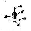
제1도 및 제2도는 아암부의 정면도 및 측면도.1 and 2 are front and side views of the arm part.
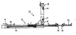
제3도 및 제4도는 팰리트 고정장치의 요부확대 정면도 및 측면도.3 and 4 are enlarged front and side views of the main part of the pallet fixing device.
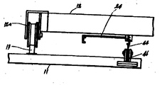
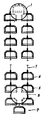
제5도 및 제6도는 입체주차장치의 정면도 및 측면도.5 and 6 are a front view and a side view of the three-dimensional parking device.
제7a~f도는 팰리트 고정장치의 동작예를 설명하기 위한 요부확대 정면도.7A-F are enlarged front views of main parts for explaining the operation example of the pallet fixing device.
제8도 내지 제16도는 선출원의 입체주차장치를 도시한 도면으로서,8 to 16 are views showing a three-dimensional parking device of the prior application,
제8도 및 제9도는 입체주차장치의 정면도 및 측면도.8 and 9 are front and side views of the three-dimensional parking device.
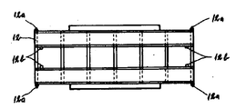
제10도는 팰리트의 평면도.10 is a plan view of a pallet.
제11도 및 제12도는 승강대의 요부확대 정면도 및 평면도.11 and 12 are enlarged front view and plan view of the platform of the platform.
제13a,b도는 신축식 아암의 동작을 설명하기 위한 개략도.13A and 13B are schematic views for explaining the operation of the telescopic arm.
제14도는 계합장치의 확대 측면도.14 is an enlarged side view of the engaging device.
제15도는 제14도의 횡단면도.FIG. 15 is a cross sectional view of FIG. 14. FIG.
제16도는 팰리트의 로크기구를 설명하기 위한 요부확대 정면도.Figure 16 is an enlarged front view of the main part for explaining the locking mechanism of the pallet.
제17도는 종래의 입체주차장치의 개략도.17 is a schematic view of a conventional three-dimensional parking device.
* 도면의 주요부분에 대한 부호의 설명* Explanation of symbols for main parts of the drawings
11, 11' : 수용랙(Rack) 12 : 팰리트11, 11 ': rack 12: pallet
15 : 승강장치 17 : 승강대15: lifting device 17: lifting platform
20 : 이송장치 21 : 신축식 아암20: feeder 21: telescopic arm
41 : 브래킷 44 : 아암부41: bracket 44: arm
46 : 웨이트부 47 : 계합부재46: weight portion 47: engagement member
48 : 팰리트 고정장치48: pallet fixing device
본 발명은 한정된 부지내에서 다수대의 자동차를 다단으로 주차시키거나 다수개의 하물을 수납하거나 하는 입체구조의 주차 혹은 하물수납장치에 있어서, 수용랙내에 팰리트를 확실하게 수용시키기 위한 장치에 관한 것이다.BACKGROUND OF THE
최근, 자동차의 증가에 따라, 시가지 등의 특히 교통량이 많은 지역에서는 주차장을 확보할 필요가 있으며, 이 때문에 한정된 설치스페이스에서 다수대의 자동차를 수용할 수 있는 입체주차장치가 보급되고 있다.In recent years, with the increase of automobiles, it is necessary to secure parking lots in areas with high traffic volume, such as urban areas, and therefore, a three-dimensional parking device capable of accommodating a large number of automobiles in a limited installation space has been spreading.
상기 종래의 입체주차장치의 일례를 제17도에 도시하고, 이하 설명한다.An example of the conventional three-dimensional parking device is shown in FIG. 17 and will be described below.
도면에 있어서, (1)은 구동스프로킷, (2)는 구동스프로킷(1)의 연직(鉛直) 하부방향에 배설된 종동스프로킷, (3)은 상기 구동스프로킷(1)과 종동스프로킷(2) 사이에 현가된 체인, (4) (4)...는, 상기 체인(3)에, 소정 피치마다 배설되어서 내부에 자동차를 수용하는 케이지를 표시한다.In the figure,
상기 구동스프로킷(1)은 도시하지 않은 구동장치에 의해 정역(正逆) 양 방향으로 적절히 회전방향을 절환해서 구동되고 , 이 구동스프로킷(1)에 현가된 체인(3)을 종동스프로킷(2)과의 사이에서 순환이동시킨다.The
상기 케이지(4)(4) ...는, 체인(3)에 대해서 각각 요동가능하게 적절한 수단에 의해서 체인(3)의 위치에 관계없이 항상 수평상태를 유지하도록 구성되어 있다. 또한, 자동차의 출입구는 최하방위치의 케이지(4)와 대체로 동일한 위치(제17도의 P의 위치)에 형성되어 있다.The cages (4) (4) ... are configured to always maintain a horizontal state regardless of the position of the chain (3) by means of appropriate means so as to be swingable relative to the chain (3). Incidentally, the entrance and exit of the automobile is formed at a position substantially the same as the cage 4 in the lowermost position (the position of P in Fig. 17).
상기 입체주차장치에 있어서, 자동차의 출입을 행하려면, 구동스프로킷(1)을 적절한 방향으로 회전시켜서, 소망의 자동차를 수용한 케이지(4) 혹은 빈 케이지(4)를 최하방 위치까지 이동시키고, 이 위치에 형성된 출입구로부터 자동차의 출입을 행한다.In the above-described three-dimensional parking device, in order to move in and out of a vehicle, the
상술한 바와 같이, 상기 종래의 입체주차장치는, 수직방향으로 순환하는 무단체인(3)에, 소정 피치마다 자동차를 수용하는 케이지(4)(4)...를 부착한 구조이기 때문에, 다음과 같은 문제가 있었다.As described above, the conventional three-dimensional parking device has a structure in which cages (4) (4) ... which accommodate an automobile at predetermined pitches are attached to an ununited (3) which circulates in the vertical direction. I had the same problem.
상기 입체주차장치에 있어서, 자동차의 출입시에 소정의 케이지(4)를 최하방의 출입구로 이동하기 위해서는, 체인(3)의 순환구동에 의해서 케이지(4)(4)…를 모두 이동시키지 않으면 안되고, 상기 소정의 케이지(4)를 출입구까지 이동시키기 위한 제어가 복잡하며, 체인(3)의 구동원으로도 대출력의 것이 필요하다. 또한 상기 모든 케이지(4)(4)... 및 케이지(4)(4)...에 수용되는 자동차의 중량은, 상기 체인(3) 및 체인(3)의 구동스프로킷(1)에 의해서 지지되는 구조이기 때문에, 강고한 지지구조가 필요하여 장치가 대형화됨과 동시에 고가인 것이 된다.In the above-described three-dimensional parking device, in order to move the predetermined cage 4 to the lowermost entrance and exit at the time of entering and exiting a vehicle, cages 4, 4,... All of them must be moved, and the control for moving the predetermined cage 4 to the entrance is complicated, and a large output is also required as a drive source of the chain 3. In addition, the weight of the vehicle accommodated in all the cages 4, 4 and 4 and 4 is driven by the
또한, 상기 체인(3)의 순환방향에 관계없이, 상기 케이지(4)를 항상 수평으로 유지할 필요가 있음과 동시에, 케이지(4)(4)...끼리가 간섭하지 않도록 케이지(4)(4)...의 배설피치 및 구동스프로킷(1)의 직경을 설정할 필요가 있기 때문에, 공간의 이용률의 향상에 제약을 받는다.In addition, it is necessary to keep the cage 4 horizontally at all times regardless of the circulation direction of the chain 3, and the cage 4 (so as not to interfere with each other). 4) Since it is necessary to set the excretion pitch and the diameter of the
또한, 입지조건의 변화에 반응시켜서 상기 장치의 자동차 수용능력을 변경하는 것은, 그 구조상의 제약에 의해서 매우 곤란하다.In addition, it is very difficult to change the vehicle capacity of the apparatus in response to changes in the location conditions due to the structural constraints.
그래서, 본 출원인은 선출원(일본국 특원소 61-222696호)에서 상기 문제점을 해결하기 위한 입체주차장치를 제안하고 있다.Therefore, the present applicant has proposed a three-dimensional parking device for solving the above problem in the earlier application (Japanese Patent Application No. 61-222696).
상기 선출원의 입체주차장치의 개요를 제8도 내지 제15도를 참조해서 이하 설명한다. 동도면에 있어서, (11)(11')는 대향배치된 다단의 수용랙으로서, 자동차(A)가 재치되는 팰리트(12)를 각 단에 수용할 수 있다. 상기 수용랙(11)(11')의 팰리트(12)의 수용부위에는, 정면 및 배면쪽에 폭방향(제8도의 좌우방향)을 따르는 레일(13)(13)...이 배설되어 있다. 그리고, 상기 각 레일 (13)(13)...의 안쪽의 소정위치에는 스토퍼부재(14)(14)...가 배치고정되어 있다.The outline of the above-described three-dimensional parking device will be described below with reference to FIGS. 8 to 15. In the same figure, (11) (11 ') is a multistage accommodating rack arrange | positioned opposingly, and can accommodate the
상기 팰리트(12)의 레일(13)(13)을 따르는 위치, 즉 폭방향의 양단 양쪽에는 팰리트(12)를 폭방향으로 이동시키기 위한 캐스터(12a)(12a)가 배설되어 있다. 또한 팰리트(12)의 하부면에서 있어서의 폭방향 양쪽의 각 2개소에는, 후크부재(12b)(12b)가 배설되어 있다.Casters 12a and 12a for moving the
(15)는 상기 수용랙(11)(11')중, 한쪽의 수용랙(11)에 배설된 승강장치로서, 구동기구(16)를 개재해서 상승강하 하는 승강대(17)를 가지고 있다. 상기 승강대(17)는 대소 2종류의 안내로울러(18)(19)(18)(19)를 개재해서 항상 수평상태를 유지한 상태에서 수용랙(11)의 측면을 상승강하 가능하게 되어 있다.15 is an elevating device disposed in one accommodating rack 11 of the accommodating racks 11 and 11 ', and has an
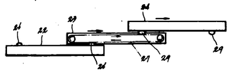
(20)은 상기 승강대(17)에 배설되어서, 상기 팰리트(12)를 수용랙(11)과 승강대(17) 사이에서 이동 방향을 변환할 수 있는 이송장치이다. 이 이송장치(20)는, 다단식의 신축식 아암(21)과, 팰리트(12)와의 계합장치(30)로 구성되고, 상기 신축식 아암(21)은 승강대(17)의 앞쪽과 뒤쪽의 2개소에, 승강대(17)의 폭방향에 부착되어 있다. 상기 신축식 아암(21)은 제1~제3아암(22)(23)(24)으로 구성되고 , 제1아암(22)은 승강대(17)에 고정되어 있다. 이 제1아암(22)에는 길이방향으로 체인(25)(25)이 장설(張設)되고, 상부면 양단부에 체인랙(26)(26)이 고착되어 있다. 제2아암(23)은 상기 제1아암(22)상에 길이방향을 일치시켜서 이동가능하게 복설(覆設)되어 있다. 이 제2아암(23)의 길이방향에는 체인(27)이 장설되고, 하부면 양단부에는 4개의 체인랙(28)(28)...이 고설되어 있으며, 이 체인랙(28)(28)...은 제1아암(22)에 배설되 체인(25)(25)의 상방측과 맞물려 있다. 따라서, 제2아암(23)은 제13도(a)에 도시한 바와 같이, 제1아암(22)내를 순환하는 체인(25)과, 체인랙(28)(28)의 맞물림에 의해서 소정방향으로 이동한다. 제3아암(24)은 상기 제2아암(23)상에 길이방향을 일치시켜서 이동가능하게 복설되어 있다. 이 제3아암(24)의 길이방향의 하부면 양단부에는 상술한 바와 같은 마찬가지의 체인랙(29)(29)이 고설되어 있으며, 이 체인랙(29)(29)은 제2아암(23)에 배설된 체인(27)의 상방향쪽과 맞물려 있다. 따라서, 제3아암(24)은 제13도(b)에 도시한 바와같이, 제2아암(23)의 이동에 따라서 제1아암(22)의 체인랙(26)과의 맞물림에 의해서 순환하는 제2아암(23)쪽의 체인(27)과 제3아암(24)의 체인랙(29)의 맞물림에 의해서, 제1아암(22)에 대한 제2아암(23)의 이동속도와 동일한 속도로, 제2아암(23)에 대해서 이동한다.20 is a conveying apparatus which is arrange | positioned at the said
또한, 상기 제3아암(24)의 외측한쪽면에 있어서의 길이방향의 대체로 중앙근처의 2개소에는 상기 팰리트(12)와의 계합장치(30)(30)가 배설되어 있다.Moreover, the engaging
상기 계합장치(30)는, 제14도 및 제15도에 도시한 바와 같이, 베이스판(31)과 베이스판(31)에 수직으로 설치되며, 서로 평행한 프레임판(32)(32)과, 상기 프레임판(32)(32)에 부착된 직선왕복운동-원운동의 변환기구(33)와 , 변환기구(33)에 배설된 계지판(34)으로 구성된다.As shown in FIGS. 14 and 15, the engaging
상기 변환기구(33)는 너트형상부재(35)와, 이 너트형상부재(35)와 나사결합하는 리이드스크류(36)를 이용한 것으로서, 상기 신축식 아암(21)의 제3아암(24)이 소정위치까지 이동한 시점에서 수용랙(11)(11')에 설치된 스토퍼부재(14)에, 리이드스크류(36)의 선단부에 고착된 수압(水壓)부재(37)가 당접하고, 제3아암(24)의 최대위치까지의 이동에 따라서 소정 스트로우크 압압된다. 이 압압에 따라서, 리이드스크류(36)는 회전하는 일이없이 축선방향으로 이동하고, 너트형상부재(35)를 일정한 방향으로 소정각도 회전시키고, 이 회전동작은 계지판(34)에 전달되어서, 계지판(34)을 소정 각도 회전시키게 된다. 상기 리이드스크류(36)의 스트로우크량은 너트형상부재(35)를 90°회전시킬 수 있는 양으로 설정되어 있으므로, 계지판(34)은 리이드스크류(36)의 소정 스트로우크의 퇴입동작마다 90°씩 회전시켜서, 상기 팰리트(12)의 후크형상부재(12)와의 계합, 이탈을 반복하는 것이다.The converter mechanism 33 uses a nut-shaped member 35 and a lead screw 36 screwed to the nut-shaped member 35, and the
그리고 이하에 상기 입체주차장치에 있어서의 자동차의 수용 및 인출요령을 설명한다. 또한, 초기상태에 있어서는, 수용랙(11)(11')에 전혀 자동차(A)가 수용되어 있지 않은 것으로 하고, 승강장치(15)는, 그 승강대(17)를 최하위 위치까지 강하시킨 상태에서 정지되어 있는 것이라고 한다. 또한 이 최초상태에서, 상기 승강대(17)의 레일(17a)(17a)에는 미리 승강장치(15) 및 이송장치(20)를 적절히 조절함으로써, 수용랙(11)(11')의 적절한 단(段)위치, 예를들면 수용랙(11)의 최상단(I)에 배설되어 있던 팰리트(12)가 재치되어 있는 것으로 한다.The following describes how to accommodate and take out automobiles in the three-dimensional parking apparatus. In addition, in the initial state, it is assumed that the vehicle A is not accommodated in the accommodation racks 11 and 11 'at all, and the
그런데, 자동차(A)를 수용하는데 있어서는, 먼저 상기 승강대(17)상의 팰리트(12)위에 자동차(A)를 이동시켜서 정지시킨다.By the way, in accommodating the automobile A, the vehicle A is first moved on the
다음에 승강장치(15)를 작동시켜서 자동차(A)를 정차시킨 상기 팰리트(12)가 본래 수용되어있던 단(I)의 높이가 될 때까지 상기 승강대(17)를 상승시킨다. 이 상태에서는, 상기의 단(I)의 레일(13)(13)과 승강대(17)의 레일(17a)(17a)이 동일한 수평면상에 직선상태로 위치하고 있다.Next, the elevating
다음에 이송장치(20)(20)를 작동시킨다. 그렇게 하면, 상술한 바와 같이, 제2아암(23)은 순환하는 체인(25)(25)과 제2아암(23)의 체인랙(28)(28)과의 맞물림에 의해서 소정방향 즉, 도면에서 오른쪽의 수용랙(11)을 향해서 제1아암(22)으로부터 돌출한다. 동시에 이 제2아암(23)의 이동에 따라서 제2아암(23)에 배설된 체인(27)은 제1아암(22)의 체인랙(26)과의 맞물림에 의해서 순환하고, 이 체인(27)의 순환동작은 이 체인(27)과 맞물리는 제3아암(24)의 체인랙(29)에 의해서 제3아암(24)에 전달되어, 상기 제3아암(24)은 제2아암(23)과 동일한 방향으로, 동일한 속도로 제2아암(23)에 대해서 돌출한다.Next, the transfer devices 20 and 20 are operated. Then, as described above, the second arm 23 is in a predetermined direction, that is, the figure by engaging the
그리고, 제3아암(24)의 길이방향 오른쪽에 배설된 계합장치(30)에 의해서, 상기 제3아암(24)과 동일한 속도로, 승강대(17)의 레일(17a)(17a)상으로부터 단(I)의 레일(13)(13)을 향해서 이동하고, 상기 제3아암(23)이 소정위치까지 돌출하면, 상기 계합장치(30)의 수압부재(37)가 수용랙(11)쪽의 스토포부재(14)와 당접해서 상대적으로 압압되기 때문에 리이드스크류(36)가 퇴입한다. 그렇게 하면, 리이드스크류(36)와 너트형상부재(35)의 맞물림에 의해서, 계지판(34)은 90°소정방향으로 회전하여, 팰리트(12)의 후크부재(12b)와 계지판(34)과의 계합상태가 해제되고, 상기 팰리트(12)는 자동차(A)를 탑재한 상태에서 수납랙(11)의 최상단(I)의 레일(13)(13)상에 재치된 상태가 된다. 이 상태에서는 상기 팰리트(12)는 상기 레일(13)(13)상에 확실하게 재치된 상태이므로, 레일(13)(13)상에서 이동하지 않도록 로크되어 있다.Then, by the engaging
다음에 상기 이송장치(20)를 역방향으로 작동시켜서, 상기 설명과 반대의 요령으로 제2, 제3아암(23)(24)을 제1아암(22)상으로 복귀시킨다. 그리고 수용랙(11)(11')의 다른 단(II)(III), (I')(II')(III')의 레일(13)(13)상의 빈 팰리트(12)중 하나를 승강대(17)상에 수용하기 위하여 상기 승강장치(15) 및 이송장치(20)를 작동시킨다. 예를들면, 도면에서 왼쪽의 수용랙(11')의 최상단(I')의 팰리트 (12)를 수용할 경우, 상기 승강대(17)를 상기 설명한 최상위치에서 정지시킨 상태로 이송장치(20)를 역방향으로 동작시켜서 상기 요령으로 제2아암(23), 제3아암(24)을 도면에서 왼쪽방향으로 향해서 돌출시킨다. 그리고 제3아암(24)이 소정위치까지 이동하면, 제3아암(24)의 길이방향 왼쪽에 배설된 계합장치(30)의 수압부재(37)가 수용랙(11')의 스토퍼부재(14)와 당접해서 상대적으로 압압됨으로써, 계지판(34)이 90°소정방향으로 회전해서 팰리트(12)의 후크부재(12b)와 계합한다.Next, the transfer device 20 is operated in the reverse direction, and the second and
이 상태에서, 이송장치(20)를 역방향으로 작동시켜서, 제2, 제3아암(23)(24)을 제1아암(22)상에 복귀시키면, 이 제3아암(24)의 퇴입동작에 의해서, 계합상태에 있는 팰리트(12)는, 수용랙(11')의 최상단(I')의 레일(13)(13)로부터 승강대(17)의 레일(17a)(17a)상으로 이동되게 된다. 그리고 이 상태에서 승강장치(15)를 작동시켜서 상기 승강대(17)를 최하위치까지 강하시킨 후, 상기 승강장치(15)를 정지시킨다.In this state, when the transfer device 20 is operated in the reverse direction and the second and
그러나, 상기 팰리트(12)를 수용랙(11)에 수용하였을 때에, 팰리트(12)가 출입구쪽으로 이동하지 않도록 확실하게 정지시키려면, 제16도에 도시한 바와 같이 레일(13)의 외측단부에 레일면을 낮게해서 단차를 형성한 수용부(13a)를 형성하고, 팰리트(12)의 수용랙(11)내로의 이동에 따라서 캐스터(12a)를 상기 수용부(13a)에 수용해서, 팰리트(12)가 출입구쪽을 향해서 이동하지 않도록 하고 있다. 그런데, 수용랙(11)의 구조가 다단이 되어서 높은 위치에 수용되어 있는 팰리트(12)가 수용랙으로부터 낙하하였을 경우에는 큰 사고를 초래하여 위험성이 높아지므로, 팰리트(12)를 수용랙(11)내에 다시 확실하게 정지시킬 필요가 있었다.However, when the
본 발명은 상기 문제점을 감안해서 제안된 것으로서, 그 문제점을 해결하기 위한 기술적 수단은, 대향 배치된 다단의 수용랙의 한쪽에 상승강하하는 승강대를 가진 승강장치를 배설하고, 상기 승강대에 배설된 이송장치의 신축식 아암을 개재해서 자동차 혹은 하물이 재치되는 팰리트를 수용랙과 승강대 사이에서 이동 변환할 수 있는 것에 있어서, 상기 수용랙에 부착된 브래킷과, 상기 브래킷에 대체로 중간부가 축지되고, 일단부에 고착된 웨이트부에 의해서 타단부가 상방향으로 돌출하도록 평형상태를 유지하고, 또한 상기 신축식 아암의 신장에 따라서 타단부가 아래로 압압되는 회전자재한 아암부와, 상기 팰리트의 일부에 상기 아암부에 대응해서 고착되어 상기 아암부의 타단부의 단면에 당접하는 계합부재를 구비시킨 것이다.SUMMARY OF THE INVENTION The present invention has been proposed in view of the above problems, and the technical means for solving the problems are provided with a lifting device having a lifting table which descends on one side of a multistage receiving rack arranged oppositely, and the transfer device installed on the lifting table. In the case where a pallet on which a vehicle or a load is placed can be shifted between a receiving rack and a platform via a telescopic arm of the bracket, an intermediate portion of the bracket attached to the receiving rack and the bracket is generally confined. The rotating arm portion, in which the other end is protruded upward by the weight part fixed to the upper part, and the other end is pressed down in accordance with the extension of the telescopic arm, and a part of the pallet It is provided with the engaging member which adhere | attaches corresponding to the said arm part, and abuts on the end surface of the other end part of the said arm part.
상기 기술적 수단에 의하면, 아암부는 일단부의 웨이트부의 중량에 의해서, 타단부가 상방향으로 돌출하도록 평형되어 있으며, 팰리트를 수용랙에 수용할 경우에는, 팰리트와 계합상태에 있는 신축식 아암의 신장에 따라서 그 전진단부가 아암부의 타단부를 아래로 압압한다. 그리고, 팰리트를 수용랙의 소정위치까지 이동시킨 후, 신축식 아암의 축퇴(縮退)에 따라서 아암부의 타단부는 상방향으로 돌출해서 평형상태를 유지하고, 이 상태에서 아암부의 타단부의 단면이 팰리트의 계합부재와 당장해서 팰리트의 출입구쪽으로의 이동을 저지한다. 한편, 팰리트를 수용랙으로부터 인출할 경우에는, 신축식 아암의 신장에 따라서 아암부의 타단부가 아래로 압압되어 팰리트의 계합부재와의 당접상태를 해제하고, 팰리트를 출입구쪽으로 이동시키는 것이다.According to the above technical means, the arm part is balanced by the weight of the weight part of one end so that the other end protrudes upward, and when the pallet is accommodated in the accommodation rack, the arm of the stretchable arm engaged with the pallet According to the elongation, the forward end portion presses down the other end of the arm portion. Then, after the pallet is moved to a predetermined position of the receiving rack, the other end of the arm part protrudes upward to maintain an equilibrium state as the telescopic arm degenerates, and in this state, the cross section of the other end of the arm part is maintained. Immediately with the engagement member of this pallet, the movement to the entrance / exit side of a pallet is prevented. On the other hand, when the pallet is withdrawn from the receiving rack, the other end of the arm portion is pushed down in accordance with the extension of the telescopic arm to release the contact state with the engagement member of the pallet, thereby moving the pallet toward the entrance. .
본 발명에 관한 팰리트 고정 장치의 일실시예를 제1도 내지 제7도에 도시한 입체주차장치를 참조해서 이하 설명한다. 단, 제8도 내지 제15도와 동일 혹은 상당부분에는 동일한 참조 부호를 붙이고, 그 설명은 생략한다. 제1도 및 제2도에 있어서, (41)은 브래킷으로서, 베이스판(42)에 프레임판(43)(43)이 서로 평행하게 수직으로 설치되어 있다. (44)는 브래킷(41)의 프레임판(43)(43)에 핀(45)으로 축지된 그 중간부가 회동자재한 아암부로서, 일단부에 웨이트부(46)를 고착하고 있다. 상기 웨이트부(46)의 중량에 의해서 아암부(44) 전체가 한쪽으로 경사되고, 웨이트부(46)의 일측면(46a)과 브래킷(41)의 프레임판(43)의 일측면(43a)이 당접해서 평형상태를 유지하고, 이 상태에서 타단부는 상방향으로 돌출하고 있다. 제3도 및 제4도는 상기 아암부(44)의 부착상태를 도시한 부분확대 정면도 및 측면도이고, 동도면에 있어서, (11)은 수용랙의 일부, (12)는 캐스터(12a)를 가진 팰리트의 일부, (24)는 신축식 아암(21)의 제3아암부의 일부, (13)은 수용랙(11)일 레일의 일부, (39)는 고무제품 등의 스토퍼를 표시한다. 상기 아암부(44)는 타단부를 수용랙(11)의 외측으로 향한 상태에서 브래킷(41)을 개재해서 수용랙(11)의 일부에 부착된다. 이 부착위치를 더욱 상세히 설명하면, 제5도 및 제6도에 도시한 바와 같이 수용랙(11)(11)의 외측근처에서 제3아암(24)의 내측부와 접촉하는 위치에 있다. 또, (47)은 팰리트(12)의 외측부 하부면에, 상기 아암부(44)에 대응해서 부착된 계합부재로서, 상기 아암부(44)의 타단부의 단면에 당접한다.An embodiment of a pallet fixing device according to the present invention will be described below with reference to the three-dimensional parking device shown in FIGS. However, the same reference numerals are given to the same or equivalent parts as those of FIGS. 8 to 15, and the description thereof is omitted. In FIG.1 and FIG.2, 41 is a bracket, and the frame boards 43 and 43 are provided in the base board 42 in parallel with each other perpendicularly. 44 is an arm part whose intermediate part pivoted by the pin 45 to the frame boards 43 and 43 of the
상기 아암부(44)와 계합부재(47)를 구비한 팰리트 고정장치의 동작예를 제7a~f도를 참조해서 이하 설명한다. 제7a도는 수용랙(11)내에 팰리트(12)가 수용되어 있는 상태를 도시하고, 이 상태에서는 아암부(44)의 타단부의 단면이 계합부재(47)에 당접하여, 팰리트(12)는 확실하게 정지하고 있다. 이 정지상태의 팰리트(12)를 승강대(17)에 이동변환할 때에는 신축식 아암(21)의 제3아암(24)를 신장시켜서, 제7도(b)에 도시한 바와 같이 제3아암(24)의 신장에 따라서 그 전진단부가 아암부(44)의 타단부를 아래로 압압하므로써, 계합부재(47)와의 당접상태가 해제된다. 또한, 이 상태에서 계합장치(30)가 작동하여, 계지판(34)이 90도 회전해서 팰리트(12)의 후크부재(12b)와 계합한다. 그리고, 제7도(c)에 도시한 바와 같이 제3아암(24)을 축퇴시킴으로써 팰리트(12)는 수용랙(11)의 출입구쪽으로부터 승강대(17) 상으로 이동한다.An operation example of the pallet fixing device including the
이어서, 승강대(17)상에 재치된 팰리트(12)를 수용랙(11)내로 이동변환할 때에는, 제7도(d)에 도시한 바와 같이 제3아암(24)과 계합상태에 있는 팰리트(12)를, 제3아암(24)을 신장시킴으로써 수용랙(11)내로 이동시킨다. 상기 제3아암(24)의 최대신장시에는, 아암부(44)의 타단부는 제7도(e)에 도시한 바와 같이 아래로 압압된 상태에 있다. 그리고, 팰리트(12)의 소정위치까지의 이동에 따라서 계합장치(30)가 작동해서 계지판(34)이 90°회전해서 팰리트(12)로부터 이탈한다. 그후, 제7도(f)에 도시한 바와 같이 제3아암(24)의 축퇴에 따라서 아암부(44)가 평형상태로 복귀되며, 타단부가 상방향으로 돌출해서, 그 타단부의 단면이 팰리트(12)의 계합부재(47)에 당접해서, 팰리트(12)의 이동이 저지되어 확실하게 정지된 상태가 된다.Subsequently, when moving the
또한, 상기 실시예에 있어서의 아암부 및 계합부재의 형상, 재질, 계수 등은 한정되는 것은 아니며, 본 발명의 범위내에서 설계변경이 가능하다.In addition, the shape, material, coefficient, etc. of the arm part and the engagement member in the said Example are not limited, A design change is possible within the scope of the present invention.
본 발명에 관한 팰리트 고정장치에 의하면, 아암부의 타단부의 단면을 팰리트의 계합부재에 당접시킨 상태에서, 팰리트를 수용랙내에 확실하게 정지시키고, 한편 신축식 아암의 신장에 의해서 상기 아암부와 계합부재와의 당접상태를 해제해서 팰리트를 이동시키는 일이 가능해진다. 따라서, 팰리트를 승강대로의 이동변환시 이외에서는, 수용랙내에 확실하게 정지시킬 수 있어, 팰리트의 수용랙내로부터의 낙하사고가 미연에 방지되어 안정성이 매우 높아진다.According to the pallet fixing device according to the present invention, in the state where the end surface of the other end of the arm portion is brought into contact with the engaging member of the pallet, the pallet is reliably stopped in the receiving rack, and the arm is extended by the extension of the arm. The pallet can be moved by releasing the contact state between the arm and the engaging member. Therefore, the pallet can be reliably stopped in the accommodation rack except at the time of the movement conversion to the hoistway, and the fall accident of the pallet from the inside of the accommodation rack is prevented in advance, and the stability is very high.
Claims (1)
Applications Claiming Priority (3)
| Application Number | Priority Date | Filing Date | Title |
|---|---|---|---|
| JP62-137086 | 1987-05-29 | ||
| JP87-137086 | 1987-05-29 | ||
| JP62137086A JPS63300173A (en) | 1987-05-29 | 1987-05-29 | Pallet fixing device |
Publications (2)
| Publication Number | Publication Date |
|---|---|
| KR880014212A KR880014212A (en) | 1988-12-23 |
| KR910008114B1 true KR910008114B1 (en) | 1991-10-10 |
Family
ID=15190556
Family Applications (1)
| Application Number | Title | Priority Date | Filing Date |
|---|---|---|---|
| KR1019870008554A KR910008114B1 (en) | 1987-05-29 | 1987-08-04 | Device for securing palettes |
Country Status (2)
| Country | Link |
|---|---|
| JP (1) | JPS63300173A (en) |
| KR (1) | KR910008114B1 (en) |
Families Citing this family (3)
| Publication number | Priority date | Publication date | Assignee | Title |
|---|---|---|---|---|
| JPH078740Y2 (en) * | 1989-06-23 | 1995-03-06 | 住友重機械工業株式会社 | Stopper mechanism for multi-level parking facility |
| DE4419517A1 (en) * | 1994-06-03 | 1995-12-07 | Basf Ag | Substituted 3-phenylpyrazoles |
| JP5415113B2 (en) * | 2008-03-19 | 2014-02-12 | Ihi運搬機械株式会社 | Mixed parking system |
-
1987
- 1987-05-29 JP JP62137086A patent/JPS63300173A/en active Granted
- 1987-08-04 KR KR1019870008554A patent/KR910008114B1/en not_active IP Right Cessation
Also Published As
| Publication number | Publication date |
|---|---|
| JPS63300173A (en) | 1988-12-07 |
| KR880014212A (en) | 1988-12-23 |
| JPH0411709B2 (en) | 1992-03-02 |
Similar Documents
| Publication | Publication Date | Title |
|---|---|---|
| CA2115720A1 (en) | Vertical-horizontal passenger-conveying system | |
| US3445010A (en) | Automatic warehousing system for bar storage | |
| CN111483736A (en) | Horizontal transfer type three-dimensional storage and conveying system | |
| KR910008114B1 (en) | Device for securing palettes | |
| KR100424949B1 (en) | Goods storage facility | |
| US3724688A (en) | Hoisting mechanism for automatic warehousing system | |
| KR100228866B1 (en) | Escalator with wheel chair stairs | |
| CN107191032B (en) | High-density and high-flow vertical annular lifting parking unit and automatic parking system | |
| CN209889765U (en) | Lifting transfer device | |
| KR910008093B1 (en) | Three dimensional parking garage | |
| CN210316711U (en) | Upper layer parking space tray lifting mechanism for avoidance-free stereo garage | |
| CN112225112A (en) | Shock attenuation formula elevating platform of electromechanical usefulness | |
| CN218143638U (en) | Transfer robot, goods shelf and storage equipment | |
| CN214732897U (en) | Loading device | |
| CN218879109U (en) | Car for elevator | |
| CN210213965U (en) | Lifting machine and conveying system | |
| JPH0689612B2 (en) | Multi-level parking device | |
| CN217895035U (en) | Carry car lifting machine suitable for track of paving | |
| US20240017920A1 (en) | Dynamic storage system and methods thereof | |
| NL2007349C2 (en) | TRANSPORT DEVICE AND SYSTEM, AND METHOD FOR USE THEREOF. | |
| RU2120012C1 (en) | Multistage mechanized car park | |
| CN115339804A (en) | Lifting machine transfer system suitable for floor track | |
| JPH11280286A (en) | Device for positioning lift table of mechanical multistoried parking device | |
| KR200157866Y1 (en) | Lifting platform for stacker type- parking apparatus | |
| JPH0637177Y2 (en) | Mechanical multilevel parking system |
Legal Events
| Date | Code | Title | Description |
|---|---|---|---|
| A201 | Request for examination | ||
| E902 | Notification of reason for refusal | ||
| G160 | Decision to publish patent application | ||
| E701 | Decision to grant or registration of patent right | ||
| GRNT | Written decision to grant | ||
| J204 | Request for invalidation trial [patent] | ||
| J206 | Request for trial to confirm the scope of a patent right | ||
| J121 | Written withdrawal of request for trial | ||
| FPAY | Annual fee payment |
Payment date: 20031008 Year of fee payment: 13 |
|
| LAPS | Lapse due to unpaid annual fee |