KR860000763B1 - Encapsulation mold with gate plate and method of using same - Google Patents
Encapsulation mold with gate plate and method of using same Download PDFInfo
- Publication number
- KR860000763B1 KR860000763B1 KR1019840000054A KR840000054A KR860000763B1 KR 860000763 B1 KR860000763 B1 KR 860000763B1 KR 1019840000054 A KR1019840000054 A KR 1019840000054A KR 840000054 A KR840000054 A KR 840000054A KR 860000763 B1 KR860000763 B1 KR 860000763B1
- Authority
- KR
- South Korea
- Prior art keywords
- mold
- outward
- plate
- hot water
- water supply
- Prior art date
Links
- 238000000034 method Methods 0.000 title claims description 28
- 238000005538 encapsulation Methods 0.000 title 1
- 239000004065 semiconductor Substances 0.000 claims abstract description 18
- XLYOFNOQVPJJNP-UHFFFAOYSA-N water Substances O XLYOFNOQVPJJNP-UHFFFAOYSA-N 0.000 claims description 68
- 239000000463 material Substances 0.000 claims description 27
- 238000000465 moulding Methods 0.000 claims description 25
- 238000007789 sealing Methods 0.000 claims description 24
- 238000002347 injection Methods 0.000 claims description 9
- 239000007924 injection Substances 0.000 claims description 9
- 239000003566 sealing material Substances 0.000 claims description 9
- 239000012530 fluid Substances 0.000 claims description 4
- 210000002268 wool Anatomy 0.000 claims 1
- 238000009826 distribution Methods 0.000 abstract description 5
- 238000005452 bending Methods 0.000 abstract 1
- 239000011347 resin Substances 0.000 abstract 1
- 229920005989 resin Polymers 0.000 abstract 1
- 239000004033 plastic Substances 0.000 description 15
- 229920003023 plastic Polymers 0.000 description 15
- 238000000926 separation method Methods 0.000 description 7
- 239000004020 conductor Substances 0.000 description 4
- 238000004140 cleaning Methods 0.000 description 3
- 238000004519 manufacturing process Methods 0.000 description 2
- ATJFFYVFTNAWJD-UHFFFAOYSA-N Tin Chemical compound [Sn] ATJFFYVFTNAWJD-UHFFFAOYSA-N 0.000 description 1
- 230000002902 bimodal effect Effects 0.000 description 1
- 238000010276 construction Methods 0.000 description 1
- 230000009977 dual effect Effects 0.000 description 1
- 239000013013 elastic material Substances 0.000 description 1
- 238000010438 heat treatment Methods 0.000 description 1
- 239000007788 liquid Substances 0.000 description 1
- 239000004848 polyfunctional curative Substances 0.000 description 1
- 238000006116 polymerization reaction Methods 0.000 description 1
- 239000000565 sealant Substances 0.000 description 1
- 239000002699 waste material Substances 0.000 description 1
Images


Classifications
-
- B—PERFORMING OPERATIONS; TRANSPORTING
- B29—WORKING OF PLASTICS; WORKING OF SUBSTANCES IN A PLASTIC STATE IN GENERAL
- B29C—SHAPING OR JOINING OF PLASTICS; SHAPING OF MATERIAL IN A PLASTIC STATE, NOT OTHERWISE PROVIDED FOR; AFTER-TREATMENT OF THE SHAPED PRODUCTS, e.g. REPAIRING
- B29C45/00—Injection moulding, i.e. forcing the required volume of moulding material through a nozzle into a closed mould; Apparatus therefor
- B29C45/14—Injection moulding, i.e. forcing the required volume of moulding material through a nozzle into a closed mould; Apparatus therefor incorporating preformed parts or layers, e.g. injection moulding around inserts or for coating articles
- B29C45/14639—Injection moulding, i.e. forcing the required volume of moulding material through a nozzle into a closed mould; Apparatus therefor incorporating preformed parts or layers, e.g. injection moulding around inserts or for coating articles for obtaining an insulating effect, e.g. for electrical components
- B29C45/14655—Injection moulding, i.e. forcing the required volume of moulding material through a nozzle into a closed mould; Apparatus therefor incorporating preformed parts or layers, e.g. injection moulding around inserts or for coating articles for obtaining an insulating effect, e.g. for electrical components connected to or mounted on a carrier, e.g. lead frame
-
- B—PERFORMING OPERATIONS; TRANSPORTING
- B29—WORKING OF PLASTICS; WORKING OF SUBSTANCES IN A PLASTIC STATE IN GENERAL
- B29C—SHAPING OR JOINING OF PLASTICS; SHAPING OF MATERIAL IN A PLASTIC STATE, NOT OTHERWISE PROVIDED FOR; AFTER-TREATMENT OF THE SHAPED PRODUCTS, e.g. REPAIRING
- B29C63/00—Lining or sheathing, i.e. applying preformed layers or sheathings of plastics; Apparatus therefor
-
- B—PERFORMING OPERATIONS; TRANSPORTING
- B29—WORKING OF PLASTICS; WORKING OF SUBSTANCES IN A PLASTIC STATE IN GENERAL
- B29C—SHAPING OR JOINING OF PLASTICS; SHAPING OF MATERIAL IN A PLASTIC STATE, NOT OTHERWISE PROVIDED FOR; AFTER-TREATMENT OF THE SHAPED PRODUCTS, e.g. REPAIRING
- B29C45/00—Injection moulding, i.e. forcing the required volume of moulding material through a nozzle into a closed mould; Apparatus therefor
- B29C45/17—Component parts, details or accessories; Auxiliary operations
- B29C45/38—Cutting-off equipment for sprues or ingates
-
- H—ELECTRICITY
- H01—ELECTRIC ELEMENTS
- H01L—SEMICONDUCTOR DEVICES NOT COVERED BY CLASS H10
- H01L21/00—Processes or apparatus adapted for the manufacture or treatment of semiconductor or solid state devices or of parts thereof
- H01L21/02—Manufacture or treatment of semiconductor devices or of parts thereof
- H01L21/04—Manufacture or treatment of semiconductor devices or of parts thereof the devices having at least one potential-jump barrier or surface barrier, e.g. PN junction, depletion layer or carrier concentration layer
- H01L21/50—Assembly of semiconductor devices using processes or apparatus not provided for in a single one of the subgroups H01L21/06 - H01L21/326, e.g. sealing of a cap to a base of a container
- H01L21/56—Encapsulations, e.g. encapsulation layers, coatings
- H01L21/565—Moulds
-
- H—ELECTRICITY
- H01—ELECTRIC ELEMENTS
- H01L—SEMICONDUCTOR DEVICES NOT COVERED BY CLASS H10
- H01L2924/00—Indexing scheme for arrangements or methods for connecting or disconnecting semiconductor or solid-state bodies as covered by H01L24/00
- H01L2924/0001—Technical content checked by a classifier
- H01L2924/0002—Not covered by any one of groups H01L24/00, H01L24/00 and H01L2224/00
Abstract
Description
제1도는 본 발명에 따른 장치의 부분분해 사시도.1 is a partially exploded perspective view of a device according to the invention.
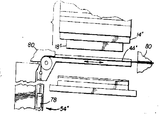
제2도는 제1도에서 보인 장치의 일부를 절개하여보인 측면도.2 is a side view of a portion of the device shown in FIG.
제3도는 본 발명에 따른 개선된 모울드의 일부를 절개하여 보인 부분 사시도.3 is a partial perspective view of a cut away portion of an improved mold according to the present invention.
제4도는 제2도의 4-4선 단면도.4 is a cross-sectional view taken along line 4-4 of FIG.
제5도는 본 발명에 따른 모울드의 일부를 절개하여보인 저면도.Figure 5 is a bottom view showing a portion of the mold according to the present invention.
제6도는 제1도 장치 일부의 다른 실시형태를 보인 측면도.6 is a side view of another embodiment of a portion of the first FIG. Device.
제7도는 제1도 장치 일부의 또 다른 실시형태를 보인 부분 측면도.7 is a partial side view showing another embodiment of a portion of the first FIG. Device.
* 도면의 주요부분에 대한 부호의 설명* Explanation of symbols for main parts of the drawings
10 : 성형장치 12 : 프레스10: forming apparatus 12: press
17 : 모울드 14, 16 : 모울드 베이스17:
18, 20 : 모울드 플레이트 22 : 제1모울드면18, 20: mold plate 22: first mold surface
24 : 급탕로망 28 : 사출공24: hot water supply network 28: injection hole
26 : 제2모울드면 30 : 모울드 구성체26: second mold surface 30: mold structure
32, 34 : 모울드베이스 대향외면 36 : 개방부32, 34: opposite the mold base 36: opening
33, 35 : 대향외면 38 : 리이드프레임스트립33, 35: facing outer 38: lead frame strip
39 : 피밀봉체 44 : 게이트플레이트39: sealed body 44: gate plate
50 : 구멍 46, 48 : 외향면50:
52 : 분리수단 54 : 모우터구성체52 separation means 54 motor configuration
60, 62 : 로울러 61, 63 : 원통형면60, 62: roller 61, 63: cylindrical surface
64, 66 : 축 72 : 분리장치64, 66: axis 72: separator
86, 70 : 단부 71 : 경회된 급탕로물질86, 70: end 71: hardened hot water supply material
74 : 분리수단74: separation means
본 발명은 밀봉물질내에서 리이드프레임스트립으로 지지되는 반도체칩과 같은 피밀봉체럴 밀봉하기 위한 방법과 장치에 관한 것이다. 특히 본 발명은 반도체 칩과 같은 전자부품을 플라스틱내에 밀봉하기위한 방법과 장치에 관한 것이다. 비록 본문으로 제한되지는 않으나 본 발명은 전자부품의 밀봉에 특히 적합하다. 예를들어 반도체장치의 제조에 있어서, 스트립평태의 리이드프레임이 제공되는 것이 상례이며, 이 스트칩은 그길이를 따라서 일정한 간격을 둔 칩지지패드를 가지며 도선들이 스트립을 따라서 각 패드에 연장되어있다.The present invention relates to a method and apparatus for sealing a hermetic seal such as a semiconductor chip supported by a lead frame strip in a sealing material. In particular, the present invention relates to methods and apparatus for sealing electronic components such as semiconductor chips in plastics. Although not limited to the text, the present invention is particularly suitable for sealing electronic components. For example, in the manufacture of semiconductor devices, it is usual to provide a lead frame in strip form, the strip chip having chip support pads spaced at regular intervals along its length and the conductors extending to each pad along the strip. .
그리고 반도체칩이 각 패드상에 지지되고 각 칩에대한 여러가지 도선에 의하여 전기적인 연결이 이루어진다. 이와같이 한 다음 스트립이 각 칩을 위한 공동을 갖는 모울드내에 놓이고 적당한 플라스틱 밀봉재가 각칩, 이로부터 연장된 도선의 일부와 칩에 대한 도선의 전기적인 연결부위를 밀봉하기 위하여 모울드내로 공급된다. 현재 사용되고 있는 전형적인 모울드는 8개 리이드프레임스트립에 적합한 것으로, 각 스트립은 10개의 리이드프레임을 가지므로 1회 사출에서 80개의 반도체장치가 밀봉된다. 동시에 120개의 반도체 장치를 밀봉하기 위하여 10개 리이드프레임 의 12개 스트립이 다른 모울드로 취급될수 있다.The semiconductor chip is supported on each pad, and electrical connection is made by various conductors for each chip. The strip is then placed in a mold with a cavity for each chip and a suitable plastic sealant is fed into the mold to seal each chip, a portion of the conductor extending therefrom and the electrical connection of the conductor to the chip. Typical molds currently in use are suitable for eight leadframe strips, each strip having ten leadframes, thus sealing 80 semiconductor devices in one injection. To seal 120 semiconductor devices at the same time, 12 strips of 10 leadframes can be treated as different molds.
일시에 밀봉될 장치의 특별한 수효에 관계없이 현재 사용되고 있는 전형적인 모울드는 상부모울드부재와 하부모울드부재로 구성된다. 상부모울드부재가 상승되고 여러개의 리이드프레임스트립이 하부모울드부재상에 놓여져 밀봉될 부분이 하부 모울드부재에 형성될 모울드공동과 일치하게 된다. 물론 하나의 공동에 대하여 하나의 스트립이 놓이게된다. 각스트립을 위하여 형성된 보상적인 공동을 갖는 상부모울드 부재가 하부모울드부재상에 하강된다.Regardless of the particular number of devices to be sealed at one time, the typical mold currently in use consists of an upper mold member and a lower mold member. The upper mold member is raised and several lead frame strips are placed on the lower mold member so that the portion to be sealed coincides with the mold cavity to be formed in the lower mold member. Of course, one strip is placed for one cavity. The upper mold member with the compensating cavity formed for the angular strip is lowered on the lower mold member.
또한 모울드에는 스트립의 길이를 따라 연장된 비교적 대형의 급탕르와 연통된 주사출공이 한모울드부재에 구비되어 있으며, 대형급탕로에는 비교적 긴 게이트급탕로가 분기되어 각 공동의 연장되어있다. 그리고 액체형태의 적당한 플라스틱의 급탕로, 게이트 및 모울드공동을 채우도록 주사축공으로 주입된다.In the mold, the injection hole communicating with a relatively large hot water supply line extending along the length of the strip is provided in the one mold member, and a relatively long gate hot water supply passage is branched in each large water supply passage to extend each cavity. Then, a hot water supply furnace of a suitable plastic in liquid form is injected into the scanning axis hole to fill the gate and the mold cavity.
플라스틱이 경화된후 상하 모울드부재가 분리되고 밀봉부분을 갖는 스트립이 모울드로부터 분리된다. 모울드부재가 분리될때에 반도체장치가 손상입지 않도록 하기위하여 밀봉된 반도체장치에 계합하여 모울드분리중에 모울드공동으로부터 이들을 밀어내도록 적어도 하나의 모울드부재상에 방출핀이 제공된다.After the plastic is cured, the upper and lower mold members are separated, and the strip having the sealing portion is separated from the mold. A release pin is provided on the at least one mold member to engage the sealed semiconductor device and to push them out of the mold cavity during mold separation so as not to damage the semiconductor device when the mold member is detached.
그리고 이러한 성형 과정이 새로운 일단의 리이드프레임스트립으로 반복된다. 비록 현재의 모울드로서 효과적인 밀봉이 가능하기는 하나 이들은 많은 결점을 갖는다. 첫째로 비가동시간이 상당한 부분을 차지한다. 매번 모울드가 사용되고, 급탕로 또는 게이트가 폐쇄되거나 공동의 일부가 그대로 채워져있는 경우 다음 성형작업을 성공적으로 수행할수 없으므로 공동, 급탕로 및 게이트가 사전에 검색되어야 하고 청결하게 유지되어야한다. 또한 성형전에 각단의 리이드프레임 스트립이 모울드내에 위치하게되고 성형후 이들을 공동으로부터 분리하는데 많은 시간이 소요된다. 아울러 모울드를 청소하는데에는 하루에 한시간 가량이 소비되는 것이 보통이다.This forming process is then repeated with a new set of leadframe strips. Although effective sealing is possible with current molds, they have many drawbacks. First, downtime is a significant part. If molds are used each time and the hot water heater or gate is closed or part of the cavity is still filled, the next molding operation cannot be performed successfully, so the cavity, hot water heater and gate must be searched in advance and kept clean. Also, leadframe strips at each end are placed in the mold before molding and it takes a long time to separate them from the cavity after molding. Also, cleaning the mold usually takes about an hour a day.
이러한 모울드부재는 고가이고, 많은 공동과 플라스틱분배급탕로를 형성하는데 상당히 정밀한 가공이 요구된다. 그밖에도, 많은 공동과 급탕로때문에 이들을 청소하기에 곤란하고 기계적인 청소의 경우 손상입기 쉽다.Such mold members are expensive and require very precise processing to form a large number of cavities and distribution pipes. In addition, many cavities and hot water heaters make it difficult to clean them and are prone to damage in the case of mechanical cleaning.
전형적으로 사용된 플라스틱은 그중합시에 경화된다. 따라서 분배계통에 채워지고 이에서 경화된 플라스틱은 모두 폐기되고 재사용이 불가능하다. 현재 사용되고 있는 모울드의 플라스틱분배망이 광범위하므로 밀봉을 위하여 실제 사용된 플라스틱에 대한 분배망의 플라스틱비율이 높아 비교적 고가인 플라스틱의 폐기량이 많게된다.Typically the plastic used is cured upon polymerization. Therefore, all plastics filled and cured in the distribution system are discarded and cannot be reused. Since the plastic distribution network of mold is widely used at present, the plastic ratio of the distribution network to the plastic actually used for the sealing is high, which leads to a large amount of waste of relatively expensive plastic.
또한 현재 사용되고 있는 모울드는 방출핀장치때문에 고가일수밖에 없다. 전형적으로 공동으로부터 반도체장치를 방출하도록 각 반도체장치에 대하여 두개의 방출핀이 제공되어있다. 따라서 120개 공동을 갖는 모울드에 대하여 240개의 방출핀을 필요로한다. 더우기 이 핀들은 반도체장치에 계합하는 부위에서 표면이 변형되게 하고 완서된 제품의 외양을 떨어뜨리고 제품에대한 표시 또는 설명문을 넣을 장소가 적어지게 한다.In addition, molds currently in use are expensive due to the release pin device. Typically two release pins are provided for each semiconductor device to release the semiconductor device from the cavity. Thus, 240 ejection pins are required for a mold having 120 cavities. Moreover, these pins cause the surface to deform at the site of engagement with the semiconductor device, reduce the appearance of the finished product, and leave less room for marking or commenting on the product.
미국 특허제4,332, 537호에 있어서는 종래 전형적인 모울드의 많은 결점을 개선한 성형장치와 방법이 기술되어있다. 이 특허문헌에 기술된 모울드와 성형방법은 제1모울드 플레이트에 대하여 동일 평면상에 일치하는 공동플레이트(cavity plate)를 갖는 제1 및 제2모울드플레이트사이에 분리 가능하게 계재되는 공동플레이트장치를 이용하고 있다. 공동 플레이트장치는 피밀봉체를 제1모울드플레이트로부터 간격을 두고 유지되게 하며 밀봉될 피밀봉체의 부분과 일치하는 개방부를 갖는다. 유체상 플라스틱이 피밀봉체의 부분을 밀봉하도곡 제1모울드플레이트에 형성된 급탕로를 통하여 주입되고 모울드플레이트로부터 외향되게 흘러나가 공동플라이트장치의 개방부도 흘러들어간다. 따라서, 피밀봉체는 모울드플레이트사이에서 공동플레이트장치의 위치선정전에 공동플레이트장치상에 예비착설될 수 있다. 또한 하부모울드플레이트는 완전히 평면상으로 되어 있어 청소가 용이하다. 또한 제1모울드 플레이트의 급탕로와 공동플레이트장치의 개방부는 주어진 모울드면적에 대하여 최대수효의피밀봉체를 밀봉할수 있도록 배열될수 있다. 또한 방출핀이 전혀 필요치 아니하며 이러한 방출핀이 사용된다면 이는 모울드플레이트가 공동플레이트장치의 분리를 위하여 옮겨질때에 제1모울드플레이트의 급탕로로부터 경화된 플라스틱을 제거하는데만 사용될 뿐이다.US Patent No. 4,332, 537 describes a molding apparatus and method which improves many of the shortcomings of conventional molds. The mold and the molding method described in this patent document utilize a cavity plate device removably interposed between the first and second mold plates having a cavity plate coplanar with respect to the first mold plate. Doing. The cavity plate arrangement allows the sealed body to be spaced from the first mold plate and has an opening that coincides with the portion of the sealed body to be sealed. The fluid-like plastic is injected through the hot water supply path formed in the first mold plate to seal the portion of the sealed body and flows outward from the mold plate so that the opening of the cavity flight device also flows. Thus, the sealed body can be pre-mounted on the joint plate device before positioning of the joint plate device between the mold plates. In addition, the lower mold plate is completely flat for easy cleaning. In addition, the hot water supply passage of the first mold plate and the opening of the cavity plate device may be arranged to seal the maximum number of sealed bodies for a given mold area. Also, no ejection pins are required and if such ejection pins are used, they are only used to remove the hardened plastic from the hot water supply path of the first moldplate when the moldplates are transferred for separation of the common plate apparatus.
미국특허제4, 332, 537호에 기술된 바와같은 장치가 전형적인 종래 기술의 모울드가 가지는 상기 언급된 문제점을 해결하는 반면에 다른 개선의 여지가 남아있다. 예를 들어 급탕로가 공동플레이트장치에 달라붙는 경향이 있으므로 비가동시간을 요구한만큼 줄일 수 없다. 또한 공동플레이트장치로부터 급탕로를 분리시키는 작업중에 공동플레이트장치가 불가피하게 마모되는 경향이 있다. 또한 소형 모울드를 가열하는 데에는 동일온도로 대형 모울드를 가열하는데 필요로하는 작동 온도보다 적은 에너지를 필요로하므로 에너지절약을 위하여 밀봉될 동수의 부품을 생산하는데 소형모울드를 이용하는 것이 바람직하다. 또한 플라스틱이 고가일뿐만아니라 플라스틱이 알맞는 양의 에너지를 필요로하는 이유때문에 플라스틱을 절략하는 것이 바람직하다. 보다 중요한 것은 급탕로를 청결하게 하는 필요성이므로 미국 특허제4, 332, 537호의 밀봉 모울드는 자동화에 적용시키기에는 이상적인것이 아니다.While the device as described in US Pat. No. 4,332,537 solves the above mentioned problems with typical prior art molds, other room for improvement remains. For example, hot water heaters tend to stick to the common plate arrangement, so downtime cannot be reduced as required. In addition, the joint plate apparatus tends to wear inevitably during the operation of separating the hot water supply path from the joint plate apparatus. In addition, heating the small mold requires less energy than the operating temperature required to heat the large mold at the same temperature, so it is desirable to use the small mold to produce the same number of parts to be sealed for energy saving. It is also desirable to cut plastics not only because they are expensive but also because they require a reasonable amount of energy. More importantly, the necessity to clean the hot water blast furnaces is such that the sealing mold of US Pat. Nos. 4,332,537 is not ideal for automation applications.
본 발명은 상기 언급된 문제점을 개선하는데 있다.The present invention is directed to improving the above mentioned problems.
본 발명의 한 관점에 따라서, 모울드가 프레스에 착설 가능하게된 한쌍의 대향된 모울드 베이스사이에 착설될 수 있도록 제공되며, 이 모울드는 리이드프레임스트립에 의하여 재가된 피밀봉체를 밀봉하는데 유용하게 되어있다. 이모울드는 대향된 제1 및 제1모울드베이스를 포함하며, 제1모울드 베이스는 급탕로망을 가지며 제2모울드베이스에 향하는 제1모울드면을 갖는다. 제1모울드베이스에는 급탕로망과 연결된 사출공이 형성되어 있다. 모울드구성체가 제1모울드면을 향하고 이로부터 일정한 간격을 둔 제1모울드베이스 대향면과 제2모울드 베이스를 향하고 이에 의하여 지지된 제2모울드베이스 대향면을 갖도록 제공된다. 이모울드구성체는 제2모울드베이스대향면을 향하여 제1모울드 베이스대향면으로부터 연장된 다수이 개방부를 갖는다. 이모울드구성체는 피밀봉체와 일치하는 개방부의 정상위치에서 리이드 프레임 스트립과 피밀봉체를 고정토록 되어있다. 하나의 게이트 플레이트가 제1 및 제2외향면을 가지며 제1회향면으로부터 제2외향면으로 다수의 게이트(구멍)을 갖도록 제공된다. 이들 구멍은 모울드가 폐쇄될때에 개방부와 일치하게된다. 이 게이트 플레이트는 제1모울드면과 제1모울드대향면 사이에 개재되며 제1외향면은 제1모울드면에 향하고 제2외향면은 제1모울드베이스 대향면을 향하게된다.According to one aspect of the present invention, a mold is provided such that it can be installed between a pair of opposed mold bases that can be installed in a press, the mold being useful for sealing a hermetically sealed object encased by a leadframe strip. have. This mold comprises opposing first and first mold bases, the first mold base having a hot water supply network and a first mold surface facing the second mold base. The first mold base has an injection hole connected to the hot water supply network. A mold structure is provided with a second mold base opposing face directed to and supported by the first mold base opposing face and the second mold base spaced at a distance from the first mold face. The mold structure has a plurality of openings extending from the first mold base opposing face toward the second mold base opposing face. This mold structure is adapted to fix the lead frame strip and the sealed body in the normal position of the opening corresponding to the sealed body. One gate plate is provided having a first and a second outward surface and a plurality of gates (holes) from the first outward surface to the second outward surface. These holes coincide with openings when the mold is closed. The gate plate is interposed between the first mold face and the first mold face, the first outward face faces the first mold face and the second outward face faces the first mold base face.
본 발명의 다른 관점에 따라서, 리이드프레임 스트립으로 지지된 피밀봉체를 밀봉하기위한 방법이 제공된다. 이방법은 모울드의 모울드구성체에 리이드프레임 스트립을 이에 의하여 지지된 피밀봉체를 얹는 단계로 구성되며, 모울드구성체는 제1모울드베이스 대향면을 가지며 제1모울드베이스에 의하여 재가된 제1모울드면으로부터 간격을 두고 있다. 제1모울드면은 급탕로망을 갖는다. 모울드 구성체는 제1모울드면에 대향되게 배열된 제2모울드베이스를 향하고 이에 의하여 지지된 제2모울드베이스대향면을 갖는다. 또한 이 모울드구성체는 제1모울드베이스 대향면으로부터 제2모울드베이스 대향면을 향하여 연장된 다수의 개방부를 가지며 피밀봉체가 이개방부내에 놓이게 된다. 평면상의 제1 및 제2외향면을 가지며 제1외향면으로부터 제2외향면으로 연장된 다수의 부멍을 갖는 게이트플레이트가 제1외향면이 제1모울드면에 향하고 제2외향면이 제1모울드베이스면을 향하도록하며 구멍들이 개방부와 일치하도록 위치하게된다. 제1 및 제2모울드베이스는 충분히 함께 이동하여 제1모울드면이 제1외향면과 접촉하고 급탕로망을 구멍과 연결하며, 제2외향면이 제1모울드베이스 대향면과 접촉한다. 유체상의 밀봉물질이 급탕로망으로 주입되고 구멍과 개방부를 통하여 흘러들어 피밀봉체를 밀봉한다. 모울드는 밀봉물질이 굳어질때까지 폐쇄상태가 유지된다. 그다음에 모울드가 개방된다.According to another aspect of the present invention, a method for sealing a hermetically sealed body supported by a leadframe strip is provided. The method consists of placing a lead frame strip on a mold structure of a mold and a sealed body supported by the mold structure, wherein the mold structure has a first mold base opposing face and is mounted from the first mold face which is refitted by the first mold base. Spaced. The first mold surface has a hot water supply network. The mold structure has a second mold base opposing face directed towards and supported by a second mold base arranged opposite the first mold face. The mold structure also has a plurality of openings extending from the first mold base opposing face toward the second mold base opposing face such that the sealed body is placed in the two open parts. A gate plate having a first and a second outward plane on a plane and having a plurality of grooves extending from the first outward plane to the second outward plane, the first outward plane facing the first mold plane and the second outward plane being the first mold Facing the base surface and the holes are positioned to coincide with the opening. The first and second mold bases are sufficiently moved together such that the first mold surface is in contact with the first outward surface and connects the hot water supply network with the hole, and the second outward surface is in contact with the first mold base opposing surface. The fluid sealing material is injected into the hot water supply network and flows through the hole and the opening to seal the sealed body. The mold remains closed until the sealing material hardens. The mold is then opened.
게이트플레이트는 급탕로망의 급탕로 경화물질을 따라 이동하고 제1모울드베이스 대향면을 측방향으로 가로 질러 이동하여 제1모울드 베이스 대향면에 제2외향면으로부터 충분히 분리되게한다. 급탕로 경화물질은 제외향면으로부터 제거된다.The gate plate moves along the hot water cured material of the hot water supply network and laterally crosses the first mold base opposing face so as to be sufficiently separated from the second outward face on the first mold base opposing face. Hot water hardened material is removed from the negative facing surface.
본 발명에 따른 모울드와 성형방법은 종래의 모울드와 성형방법보다 현저한 잇점을 제공한다. 급탕로망은 급탕로 경화물질을 게이트플레이트상에만 퇴적되게하고 게이트플레이트가 모울드가 급탕로경화물질을 따라 개방된후 모울드부터 측방향으로 이동될 수 있게되어있으므로 성형구조물의 마모를 크게 줄일 수 있다. 또한 급탕로경화물질이 성형 구조물상에 남겨져 있지 않게되므로 급탕로를 청소할 필요가 없다. 이는 비가동시간을 크게 줄여준다. 또한 모울드부터 측방향으로 이동 가능한 게이트플레이트를 사용하고 급탕로의 편의적인 배치를 통하여 미국특허제4, 332, 537호의 공동플레이트장치와 같은 성형구조물의 자동적인 공급에 이상적인 장치를 제공할 수 있다. 실제로 본 발명의 개선된 모울드와 방법을 이용하여 단위 시간당 2-3번의 성형과정이 수행될 수 있다. 또한 동일한 생산을 위하여 소형 모울드가 사용될 수 있다. 따라서 대형성형구조물의 긴급탕로를 필요로하지 않으므로 사용된 플라스틱 물질의 양을 10%이상 줄일수 있다. 이는 경비와 에너지를 현저히 절략할수 있도록 하는 것이다.The mold and molding method according to the present invention provides significant advantages over conventional mold and molding methods. The hot water supply network allows the hot water cured material to be deposited only on the gate plate, and the gate plate can be moved laterally from the mold after the mold is opened along the hot water hardener material, thereby greatly reducing the wear of the molded structure. In addition, the hot water supply hardened material is not left on the molding structure, so the hot water supply furnace does not need to be cleaned. This greatly reduces downtime. In addition, by using a gate plate movable laterally from the mold and through the convenient arrangement of the hot water heater, it is possible to provide an ideal device for the automatic supply of the molded structure, such as the joint plate device of US Patent No. 4,332,537. Indeed, 2-3 molding processes per unit time can be performed using the improved molds and methods of the present invention. Small molds can also be used for the same production. This eliminates the need for an emergency squirt on large shaped structures, thus reducing the amount of plastic material used by more than 10%. This makes it possible to significantly cut costs and energy.
본 발명에 따른 모울드와 성형방법을 이용할때에 공동플레이트 장치의 마모를 현저히 줄일수 있으며, 마모된 성형장치를 교체할 비용이 현저히 감소된다.When using the mold and the molding method according to the present invention can significantly reduce the wear of the joint plate device, the cost of replacing the worn molding device is significantly reduced.
본 발명을 첨부 도면에 의거하여 보다 상세히 설명하면 다음과 같다.The present invention will be described in more detail with reference to the accompanying drawings.
제1도는 본발명에 따른 성형장치(10)를 보인 것이다. 공지의 프레스(12)는 한쌍의 대향된 제1모울드 베이스(14)와 제2모울드베이스(16)를 갖는다. 성형장치(10)의 요부를 이루는 모울드(17)는 제3도 및 제4도에서 상세히 설명될 것이다. 제1모울드 베이스(14)는 이에 착설된 제1모울드플레이트(18)를 가지며, 제2모울드베이스(16)에는 제2모울드플레이트(20)가 착설되어있다. 제1모울드플레이트(18)는 급탕로망(24)를 갖는 제1모울드면(22)을 갖는다. 제2모울드플레이트(20)는 제1모울드면(22)을 향한 제2모울드면(26)을 갖는다. 제1모울드플레이트(18)의 사출공(28)(제3도)은 제1모울드면(22)의 급탕로망(24)와 연통되어있다. 도시된 실시형태에서, 제1모울드 베이스(18)는 급탕로망(24)을 가지며 사출공(28)을 통하여 하측으로 주입이 이루어진다. 이러한 배열은 임의적인 것으로 작업을 보다 용이하게하기 위하여 전체배열을 180°각도로 회전시킬수 있음을 이해할 수 있을 것이다.1 shows a
제4도에서 가장 상세히 도시된 모울드구성체(30)는 제1모울드면(22)을 향하고 이로부터 일정한 간격을 둔 제1모울드 베이스 대향회면(32)을 갖는다. 또한 모울드구성체(30)는 제2모울드베이스(16)을 향하고 이에의하여 지지된 제2모울드베이스 대향외면(34)을 포함한다. 또한 제1 및 제2 대향내면(33)(35)도 모울드구성체(30)의 일부를 이룬다. 모울드 구성체(30)는 제1모울드 베이스 대향면(32)로부터 제2모울드베이스 대향면(34)을 향하여 연장된 다수의 개방부(36)를 갖는다. 모울드 구성체(30)는 피밀봉체(39)와 개방부(36)가 정상위치에서 일치하도록 리이드프레임스트립(38)과 이에 의하여 지지되고 밀봉된 피밀봉체(39)를 지지하게되어있다. 구체화된 모울드구성체(30)는 제1내면(33)을 갖는 제1공동플레이트(40)와 제2내면(35)를 갖는 제2공동플레이트(42)를 포함하는 공동플레이트구성체이다. 일반적으로 리이드프레임스트립(38)은 제1공동플레이트(40)와 제2공동플레이트(42)사이에 지지된다. 제1외면(32)과 제2외면(34)은 각각 플레이트(40)(42)에 의하여 형성되고 대체로 평면상이며 상호 대향되어있다. 제1내면(33)과 제2내면(35) 사이에 리이드프레임스트립(38)과 이에 부착된 피밀봉체(39)는 제1모울드플레이트(18)로부터 완전히 일정한 간격을 두로 유지되어있다.The mold construct 30 shown in detail in FIG. 4 has a first mold
본 발명에 따라서, 게이트플레이트(44)가 제공되는바, 이는 제1외향면(46)과 제2외향면(48)을 갖는다. 또한 게이트플레이트(44)는 제1외향면(46)으로부터 제2외향면(48)으로 연장된 다수의 소형게이트 또는 구멍(50)(제3도 참조)을 갖는다. 구멍(50)은 매우 작으며 프레스(12)가 폐쇄될때에 개방부(36)와 일치한다. 게이트플레이트(44)는 제1모울드면(22)과 제1외면(32)사이에 위치하고 제1외향면(46)이 제1모울드면(22)에 향하고 제2외향면(32)에 향한다.According to the invention, a
제1도와 제2도에 있어서, 제1모울드 베이스(14)를 제2모울드베이스(16)로부터 분리하여 이동시킬때에 공동플레이트구성체(30)와 제1모울드플레이트(18)로부터 게이트플레이트(44)의 외향면(46), (48)을 분리하기위한 제1분리수단(52)을 볼 수 있다. 이분리수단(52)은 이러한 분리과정중에 공동플레이트구성체(30)가 제2모울드플레이트(20)과 접촉이 유지되게 한다. 제1도와 제2도에 도시된 이 특별한 분리수단(52)은 게이트플레이트(44)를 공동플레이트구성체(30)와 제1모울드플레이트(18)과 선택적으로 정렬되고 측방향으로 가로질러 이동하도록 연결된 모우터구성체(54)로 구성된다. 또한 분리수단(52)은 게이트플레이트(44)의 측변부(56)(57)를 안내하기위한 한쌍의 안내구(55)와 게이트플레이트(44)에 의하여 형성된 평면에 대하여 평행하고 또한 상호 평행하게되어있는 축(64)(66)을 갖는 한쌍의 로울러(60)(62)로 구성된다. 이로울러(60)(62)는 공동플레이트구성체(30)의 양단부(68)(70)에 대하여 평행하고 이들로부터 측방향으로 일정한 간격을 두고있다. 게이트플레이트(44)는 로울러(60)(62)상에 놓여져 모우터 구성체(54)에 의하여 이동하게 되어있다. 로울러(60)(62)는 프레스(12)가 개방될때에 게이트플레이트(44)상에 상승력을 충분히 제공할수 있는 원통형면(61)(63)을 갖는다. 이는 분리수단(52)의 작용에 도움이 된다.1 and 2, the
일반적으로 게이트플레이트(44)는 가요성 재질, 좋기로는 스프링재질과 같은 탄성재질로되어 있어 로울러(60)(62)상을 이동할수 있도록 되어있다.In general, the
게이트플레이트(44)는 그 두께가 1㎜이하인 주석으로 되어있다. 가요성의 게이트플레이트(44)가 로울러(60)(62)상을 이동할때에 급탕로망(24)로부터의 경화된 급탕로망물질(71)은 이급탕로망물질(71)이 가요성이 아니고 프레스(12)가 개방되었을 때에 그 접착성때문에 그리고 개방부(26)내의 경화된 물질에 구멍(50)을 통하여 연결되어 있기때문에 게이트플레이트(44)에 달라붙어서 게이트플레이트(44)의 제1외향면(46)과 함께 이동하여 가요성게이트플레이트(44)가 원통평면(61)(63)상에서 만곡되어 이동할때에 분리된다. 변부(73)를 갖는 보조분리장치(72)가 일측 또는 양측의 로울러(60)(62)가까이에 착설되어 게이트플레이트(44)의 제1외향면(50)에 붙어있는 급탕로 물질(71)을 분리시키도록하는데 도움을 준다. 따라서 로울로(60)(62)의 원통형면(61)(63)을 따라서 분리장치(72)와 변부(73)는 매번의 밀봉주기때마다 게이트플레이트(44)의 제1외향면(46)에 접착된 급탕로 물질(71)을 분리시키는 분리수단(74)으로서 작용한다.The
이와같이 분리수단(52)은 급탕로망(24)에 퇴적되어 게이트플레이트(44)의 제1외향면(46)에 부착되어 남아있는 경화된 급탕로 물질(71)을 따라서 게이트플레이트(44)를 이동시키는 수단으로서 작용하며 제1외면(32)을 측방향으로 가로질러 제1모울드면(22)과 선택적으로 정렬될수 있도록 제1외향면을 이동시킨다.In this way, the separating means 52 is deposited on the hot
제6도는 모우터수단(54')이 로타리모우터(76)로 구성되고 게이트플레이트(44')가 로울로(60')(62')를 타고 이동하는 무단벨트(44')로 구성된 바와 본 발명의 다른 실시형태를 보인것이다. 일반적으로 무단벨트(44')는 제1모울드면(22')과 교대로 정렬되는 다수의 제1외향면(46')을 갖는다.6 shows that the motor means 54 'is composed of a
제7도는 모우터수단(54")이 단일의 이중작용 실린더(78)로 구성되고 안내구(80)가 게이트플레이트(44")의 운동방향으로 향하는 본 발명의 한 실시형태를 보인 것이다.7 shows an embodiment of the invention in which the motor means 54 "consists of a single
본 발명에 따라서 리이드프레임프트립(38)에 의하여 고정된 피밀봉체(39)를 밀봉하기 위한 방법이 제공된다. 이방법은 프레스(12)에 높일수 있는 모우드구성체(30)에 리이드프레임스트립(38)과, 이에 의하여 고정된 피밀봉체(39)를 얹는 단계로 구성된다. 모울드구성체(30)는 제1모울드 베이스(14)에 의하여 재기된 제1모울드면(22)을 향하고 이로부터 일정한 간격을 둔 제1모울드 베이스 대향외면(32)을 갖는다. 제1모울드면(22)은이에 급탕로망(24)을 갖는다. 모울드구성체(30)는 또한 제2모울드면(16)을 향하고 이에 의하여 지지된 제2모울드베이스 대향외면(34)을 갖는다. 제2모울드베이스(16)는 제1모울드면(22)에 대하여 반대쪽에 정렬되어있다. 이모울드 구성체는 제2모울드베이스 대향면(34)를 갖는다. 리이드프레임스트립(38)은 이에 의하여 지지된 피밀봉체(39)가 개방부(36)내에 위치하도록 모울드구성체(30)에 얹혀진다. 도시된 실시형태에 있어서 모울드구성체(30)는 제1공동플레이트(40)과 제2공동플레이트(42)를 모두 포함하는 공동플레이트구성체의 형태로 되어있다. 리이드프레임스트립(38)은 제1공동플레이트(40)과 제2공동플레이트(42)사이에 놓이고 제2모울드플레이트(20)의 제2모울드면(26)의 상부에 공동플레이트 구성체(30)를 위치되게하므로서 리이드프레임스트립(38)과 피밀봉체(39)를 모울드구성체(30)에 얹는 과정이 수행된다.According to the present invention there is provided a method for sealing a hermetic seal 39 fixed by a lead
평면상의 제1외향면(46), 역시 평면상인 제2외향면(48)과, 제1외향면(46)으로부터 제2외향면(48)으로 연장된 다수의 구멍(50)을 갖는 게이트플레이트(44)는 제1외향면(46)이 제1모울드면(22)에 향하고 제2외향면(48)이 제1외향면(32)에 향하며 구멍(50)이 개방부(36)에 일치하도록 위치된다. 일반적으로 게이트플레이트(44)는 제2외향면(32)이 제2외향면(48)과 충분히 정렬되고 구멍(50)이 개방부(36)와 급탕로망(24)에 일치하게 제1외면(32)을 측방향으로 가로질러 이동시키므로서 위치될수 있을 것이다.A gate plate having a planar first
제1모울드 베이스(14)와 제2모울드 베이스(16)이 충분히 함께 이동하여 제1모울드면(22)이 게이트플레이트(44)의 제1외향면(46)과 접촉하고 급탕로망(24)을 구멍(50)에 연결한다. 제1모울드 베이스(14)와 제2모울드 베이스(16)의 이동은 게이트플레이트(44)의 제2외향면(48)이 공동플레이트구성체(30)의 제1외면(32)과 충분히 접촉되게 한다.The
유체상의 밀봉물질이 사출공(28)을 통하여 급탕로망(24)로 공급되어 개방부(36)내에 고정되어있는 피밀봉체(39)를 밀봉한다. 프레스(12)는 밀봉물질이 경화될때까지 폐쇄상태가 유지된다. 그후 프레스(12)가 개방된다.The fluid sealing material is supplied to the hot
급탕로망(24)으로부터 경화된 급탕로물질(71)과 함께 게이트플레이트(44)는 제1외면(32)를 가로질러 측방향으로 이동하므로서 제1외면(32)을 제2외향면(48)으로부터 분리되게 한다. 경화된 급탕로 물질이 제1외향면(46)으로부터 분리된다.The
피밀봉체(39)와 함께 리이드프레임스트립(38)은 모든 공동플레이트구성체(30)를 옮기어 필요한 분리과정을 거치므로서 공동플레이트구성체(30)으로부터 분리된다. 그리고 교체된 리이드프레임스트립(38)과 함께 교체된 공동플레이트(30)가 제1모울드 플레이트(20)와 게이트플레이트(44)사이에 삽입된다. 교체된 공동플레이트구성체(30)는 제1도에 도시된바와 같은 구성으로 게이트플레이트(44)의 운동방향으로 이동된다. 이와같이 하므로서 공동플레이트구성체(30)의 공급을 위하여 자동장치가 사용될수 있다.The
본 발명의 개선된 성형장치(10)와 피밀봉체(39)의 플라스틱 밀봉방법은 리이드프레임스트립(38)로 고정된 반도체칩과 같은 피밀봉체를 밀벙하기 위한 산업분야에 이용될수 있다.The
Claims (17)
Applications Claiming Priority (2)
| Application Number | Priority Date | Filing Date | Title |
|---|---|---|---|
| US06/456,693 US4442056A (en) | 1980-12-06 | 1983-01-10 | Encapsulation mold with gate plate and method of using same |
| US456693 | 1983-01-10 |
Publications (2)
| Publication Number | Publication Date |
|---|---|
| KR840007382A KR840007382A (en) | 1984-12-07 |
| KR860000763B1 true KR860000763B1 (en) | 1986-06-23 |
Family
ID=23813775
Family Applications (1)
| Application Number | Title | Priority Date | Filing Date |
|---|---|---|---|
| KR1019840000054A KR860000763B1 (en) | 1983-01-10 | 1984-01-09 | Encapsulation mold with gate plate and method of using same |
Country Status (6)
| Country | Link |
|---|---|
| US (1) | US4442056A (en) |
| EP (1) | EP0113692A3 (en) |
| JP (1) | JPS59155139A (en) |
| KR (1) | KR860000763B1 (en) |
| CA (1) | CA1211606A (en) |
| PH (1) | PH20820A (en) |
Families Citing this family (27)
| Publication number | Priority date | Publication date | Assignee | Title |
|---|---|---|---|---|
| US4537739A (en) * | 1983-08-22 | 1985-08-27 | Replicap Products, Inc. | Production of molded plastic articles with artwork thereon |
| US4877387A (en) * | 1984-03-06 | 1989-10-31 | Asm Fico Tooling, B.V. | Automatic continuously cycleable molding system |
| US4872825A (en) * | 1984-05-23 | 1989-10-10 | Ross Milton I | Method and apparatus for making encapsulated electronic circuit devices |
| US4954308A (en) * | 1988-03-04 | 1990-09-04 | Citizen Watch Co., Ltd. | Resin encapsulating method |
| US5044912A (en) * | 1989-12-11 | 1991-09-03 | Motorola, Inc. | Mold assembly having positioning means |
| JP2644074B2 (en) * | 1990-09-27 | 1997-08-25 | シャープ株式会社 | Split spray method for release agent |
| US5316463A (en) * | 1992-11-24 | 1994-05-31 | Neu Dynamics Corporation | Encapsulating molding equipment |
| US5429488A (en) * | 1992-11-24 | 1995-07-04 | Neu Dynamics Corporation | Encapsulating molding equipment and method |
| US5409362A (en) * | 1992-11-24 | 1995-04-25 | Neu Dynamics Corp. | Encapsulation molding equipment |
| US5405255A (en) * | 1992-11-24 | 1995-04-11 | Neu Dynamics Corp. | Encapsulaton molding equipment |
| US5344296A (en) * | 1993-07-06 | 1994-09-06 | Motorola, Inc. | Method and apparatus for forming a runner in a mold assembly |
| TW257745B (en) * | 1993-07-22 | 1995-09-21 | Towa Kk | |
| US6007316A (en) * | 1993-07-22 | 1999-12-28 | Towa Corporation | Apparatus for molding resin to seal electronic parts |
| MY114536A (en) * | 1994-11-24 | 2002-11-30 | Apic Yamada Corp | A resin molding machine and a method of resin molding |
| USH1654H (en) * | 1995-01-10 | 1997-06-03 | Rounds; Nicholas A. | Transfer molding process for encapsulating semiconductor devices |
| NL9500238A (en) * | 1995-02-09 | 1996-09-02 | Fico Bv | Casing device with compensation element. |
| JP3246848B2 (en) * | 1995-02-22 | 2002-01-15 | アピックヤマダ株式会社 | General-purpose gate position resin molding apparatus and resin molding method |
| US5833903A (en) * | 1996-12-10 | 1998-11-10 | Great American Gumball Corporation | Injection molding encapsulation for an electronic device directly onto a substrate |
| SG64985A1 (en) * | 1997-05-06 | 1999-05-25 | Advanced Systems Automation Li | Method and apparatus for moulding plastic packages |
| US6817854B2 (en) * | 2002-05-20 | 2004-11-16 | Stmicroelectronics, Inc. | Mold with compensating base |
| TWI327756B (en) * | 2002-11-29 | 2010-07-21 | Apic Yamada Corp | Resin molding machine |
| US7189601B2 (en) * | 2004-03-02 | 2007-03-13 | Texas Instruments Incorporated | System and method for forming mold caps over integrated circuit devices |
| JP4084844B2 (en) * | 2005-09-27 | 2008-04-30 | Towa株式会社 | Resin sealing molding method and apparatus for electronic parts |
| CN102896744B (en) * | 2012-10-12 | 2015-04-08 | 青岛海信模具有限公司 | Mold ejection structure and application method thereof |
| RU2015156497A (en) * | 2013-06-04 | 2017-07-14 | Абео А/С | METHOD FOR PRODUCING A BUILDING ELEMENT, DEVICE FOR MANUFACTURE OF A BUILDING ELEMENT AND A BUILDING ELEMENT MANUFACTURED BY THIS METHOD |
| US9539743B2 (en) * | 2014-07-02 | 2017-01-10 | Gregory Arther Huber | Insertable aperture molding |
| KR20170055787A (en) * | 2015-11-12 | 2017-05-22 | 삼성전자주식회사 | molding apparatus for manufacturing semiconductor package and molding method of semiconductor package using the same |
Family Cites Families (13)
| Publication number | Priority date | Publication date | Assignee | Title |
|---|---|---|---|---|
| DE564464C (en) * | 1932-02-23 | 1932-11-19 | Otto Sanner | Device for the production of bodies from hardenable condensation products |
| US2163814A (en) * | 1935-09-04 | 1939-06-27 | Firm D Swarovski Glasfabrik Un | Manufacturing of jewelry set with stones |
| US2500258A (en) * | 1943-06-24 | 1950-03-14 | Mazzoni Lucien | Injection mold |
| US2382200A (en) * | 1944-02-22 | 1945-08-14 | Western Electric Co | Molding apparatus |
| US2415961A (en) * | 1944-09-22 | 1947-02-18 | Nast Leo | Mold for producing shapes of plastic material |
| US2650648A (en) * | 1952-08-13 | 1953-09-01 | American Seating Co | Chair structure |
| FR1075649A (en) * | 1953-03-13 | 1954-10-19 | Method and device for removing carrots in injection molding machines | |
| GB927800A (en) * | 1960-07-14 | 1963-06-06 | Turner Machinery Ltd | Sprue removal in injection moulding machines |
| US3753634A (en) * | 1970-10-09 | 1973-08-21 | T Bliven | Molding means for strip frame semiconductive device |
| US3779506A (en) * | 1971-08-25 | 1973-12-18 | Motorola Inc | Apparatus for equalizing the flow rate of molding compound into each of a series of mold cavities |
| FR2297712A1 (en) * | 1975-01-14 | 1976-08-13 | Profil Sa Ind Financ Le | Insert loading device for composite injection mouldings - to facilitate mfr. of plastic coated automobile fittings |
| JPS5253663A (en) * | 1975-10-29 | 1977-04-30 | Hitachi Ltd | Resin sealing mold |
| US4332537A (en) * | 1978-07-17 | 1982-06-01 | Dusan Slepcevic | Encapsulation mold with removable cavity plates |
-
1983
- 1983-01-10 US US06/456,693 patent/US4442056A/en not_active Expired - Lifetime
- 1983-12-30 CA CA000444489A patent/CA1211606A/en not_active Expired
-
1984
- 1984-01-04 EP EP84300029A patent/EP0113692A3/en not_active Withdrawn
- 1984-01-06 PH PH30072A patent/PH20820A/en unknown
- 1984-01-09 KR KR1019840000054A patent/KR860000763B1/en not_active IP Right Cessation
- 1984-01-10 JP JP59001415A patent/JPS59155139A/en active Granted
Also Published As
| Publication number | Publication date |
|---|---|
| JPS59155139A (en) | 1984-09-04 |
| JPH0120533B2 (en) | 1989-04-17 |
| CA1211606A (en) | 1986-09-23 |
| PH20820A (en) | 1987-04-24 |
| EP0113692A3 (en) | 1985-12-27 |
| EP0113692A2 (en) | 1984-07-18 |
| KR840007382A (en) | 1984-12-07 |
| US4442056A (en) | 1984-04-10 |
Similar Documents
| Publication | Publication Date | Title |
|---|---|---|
| KR860000763B1 (en) | Encapsulation mold with gate plate and method of using same | |
| US5846477A (en) | Production method for encapsulating a semiconductor device | |
| US5252051A (en) | Resin-seal apparatus for semiconductor element | |
| EP0688650B1 (en) | Method of resin-sealing semiconductor devices | |
| JPH04147814A (en) | Mold for resin seal molding | |
| KR20030026996A (en) | Mold cleaning sheet and method of producing semiconductor devices using the same | |
| JPH11126787A (en) | Method and mold for resin sealing electronic component | |
| US20180174864A1 (en) | Manufacturing method for semiconductor device | |
| JPH0432755Y2 (en) | ||
| JPS6058813A (en) | Mold | |
| JPS5933838A (en) | Metal mold for resin sealing of semiconductor | |
| JPS61114824A (en) | Resin molding apparatus | |
| WO2024048929A1 (en) | Mold for injection molding | |
| JPH08279525A (en) | Semiconductor molding device | |
| JPH11330112A (en) | Manufacture of semiconductor device and transfer mold device thereof | |
| JPS6359511A (en) | Resin molding equipment | |
| JP3575592B2 (en) | Mold for resin molding of lead frame assembly and resin molding method | |
| JPH0637129A (en) | Molding die, lead frame, and manufacture of semiconductor device | |
| JP2681387B2 (en) | Mold press equipment | |
| JPH0620578Y2 (en) | Semiconductor injection molding machine | |
| JPH0546897Y2 (en) | ||
| JPH0642336Y2 (en) | Semiconductor element resin sealing device | |
| CN114559603A (en) | Rubber coating mold and rubber coating process | |
| KR910013493A (en) | Resin sealing molding method for electronic parts, molding apparatus thereof and mold for molding thereof | |
| JPH03256712A (en) | Transfer molding machine |
Legal Events
| Date | Code | Title | Description |
|---|---|---|---|
| A201 | Request for examination | ||
| G160 | Decision to publish patent application | ||
| E701 | Decision to grant or registration of patent right | ||
| GRNT | Written decision to grant | ||
| FPAY | Annual fee payment |
Payment date: 20010622 Year of fee payment: 16 |
|
| LAPS | Lapse due to unpaid annual fee |