KR20220162809A - Gas enclosure systems and methods utilizing an auxiliary enclosure - Google Patents
Gas enclosure systems and methods utilizing an auxiliary enclosure Download PDFInfo
- Publication number
- KR20220162809A KR20220162809A KR1020227040440A KR20227040440A KR20220162809A KR 20220162809 A KR20220162809 A KR 20220162809A KR 1020227040440 A KR1020227040440 A KR 1020227040440A KR 20227040440 A KR20227040440 A KR 20227040440A KR 20220162809 A KR20220162809 A KR 20220162809A
- Authority
- KR
- South Korea
- Prior art keywords
- enclosure
- assembly
- printhead
- gas
- various embodiments
- Prior art date
Links
- 238000000034 method Methods 0.000 title abstract description 238
- 238000007639 printing Methods 0.000 claims abstract description 419
- 239000000758 substrate Substances 0.000 claims description 210
- 239000012530 fluid Substances 0.000 claims description 60
- 238000001914 filtration Methods 0.000 claims description 50
- 238000004891 communication Methods 0.000 claims description 41
- 239000013618 particulate matter Substances 0.000 claims description 19
- 230000008569 process Effects 0.000 abstract description 86
- 238000012423 maintenance Methods 0.000 abstract description 44
- 238000005259 measurement Methods 0.000 abstract description 34
- 239000007789 gas Substances 0.000 description 787
- 238000007726 management method Methods 0.000 description 272
- 239000000463 material Substances 0.000 description 119
- 239000011261 inert gas Substances 0.000 description 113
- 230000000712 assembly Effects 0.000 description 74
- 238000000429 assembly Methods 0.000 description 74
- 238000000746 purification Methods 0.000 description 71
- 238000012546 transfer Methods 0.000 description 54
- 239000003570 air Substances 0.000 description 52
- 239000000976 ink Substances 0.000 description 51
- 239000012636 effector Substances 0.000 description 46
- XLYOFNOQVPJJNP-UHFFFAOYSA-N water Chemical compound O XLYOFNOQVPJJNP-UHFFFAOYSA-N 0.000 description 41
- 238000007789 sealing Methods 0.000 description 40
- 239000002245 particle Substances 0.000 description 39
- 230000033001 locomotion Effects 0.000 description 32
- QVGXLLKOCUKJST-UHFFFAOYSA-N atomic oxygen Chemical compound [O] QVGXLLKOCUKJST-UHFFFAOYSA-N 0.000 description 28
- 230000000670 limiting effect Effects 0.000 description 28
- 238000003032 molecular docking Methods 0.000 description 28
- 229910052760 oxygen Inorganic materials 0.000 description 28
- 239000001301 oxygen Substances 0.000 description 28
- 125000006850 spacer group Chemical group 0.000 description 26
- 239000000356 contaminant Substances 0.000 description 25
- 238000004519 manufacturing process Methods 0.000 description 25
- 239000002699 waste material Substances 0.000 description 22
- 238000010926 purge Methods 0.000 description 21
- 238000011084 recovery Methods 0.000 description 21
- IJGRMHOSHXDMSA-UHFFFAOYSA-N Atomic nitrogen Chemical compound N#N IJGRMHOSHXDMSA-UHFFFAOYSA-N 0.000 description 20
- 239000000123 paper Substances 0.000 description 20
- 238000007641 inkjet printing Methods 0.000 description 19
- 239000010410 layer Substances 0.000 description 18
- 238000005516 engineering process Methods 0.000 description 17
- 238000009432 framing Methods 0.000 description 17
- 229910052751 metal Inorganic materials 0.000 description 17
- 239000002184 metal Substances 0.000 description 17
- 238000007667 floating Methods 0.000 description 16
- 239000002808 molecular sieve Substances 0.000 description 16
- 239000003960 organic solvent Substances 0.000 description 16
- URGAHOPLAPQHLN-UHFFFAOYSA-N sodium aluminosilicate Chemical compound [Na+].[Al+3].[O-][Si]([O-])=O.[O-][Si]([O-])=O URGAHOPLAPQHLN-UHFFFAOYSA-N 0.000 description 16
- 239000002904 solvent Substances 0.000 description 16
- 239000011521 glass Substances 0.000 description 15
- 230000003044 adaptive effect Effects 0.000 description 14
- 230000007613 environmental effect Effects 0.000 description 14
- 238000012545 processing Methods 0.000 description 14
- 239000000203 mixture Substances 0.000 description 12
- 230000006835 compression Effects 0.000 description 11
- 238000007906 compression Methods 0.000 description 11
- 238000011109 contamination Methods 0.000 description 11
- 229920000642 polymer Polymers 0.000 description 11
- 238000012360 testing method Methods 0.000 description 11
- 238000010276 construction Methods 0.000 description 10
- 238000010586 diagram Methods 0.000 description 10
- 229910052757 nitrogen Inorganic materials 0.000 description 10
- 241000894007 species Species 0.000 description 10
- 230000006870 function Effects 0.000 description 9
- 230000000737 periodic effect Effects 0.000 description 9
- 230000001105 regulatory effect Effects 0.000 description 9
- 229920002943 EPDM rubber Polymers 0.000 description 8
- 238000010304 firing Methods 0.000 description 8
- 238000003780 insertion Methods 0.000 description 8
- 230000037431 insertion Effects 0.000 description 8
- 229910052756 noble gas Inorganic materials 0.000 description 7
- 238000001228 spectrum Methods 0.000 description 7
- OKTJSMMVPCPJKN-UHFFFAOYSA-N Carbon Chemical compound [C] OKTJSMMVPCPJKN-UHFFFAOYSA-N 0.000 description 6
- 239000002131 composite material Substances 0.000 description 6
- 238000013461 design Methods 0.000 description 6
- 238000009792 diffusion process Methods 0.000 description 6
- 230000037452 priming Effects 0.000 description 6
- 230000007704 transition Effects 0.000 description 6
- 229910000831 Steel Inorganic materials 0.000 description 5
- 229910052782 aluminium Inorganic materials 0.000 description 5
- XAGFODPZIPBFFR-UHFFFAOYSA-N aluminium Chemical compound [Al] XAGFODPZIPBFFR-UHFFFAOYSA-N 0.000 description 5
- 238000005538 encapsulation Methods 0.000 description 5
- 238000009472 formulation Methods 0.000 description 5
- 238000009434 installation Methods 0.000 description 5
- 238000002955 isolation Methods 0.000 description 5
- 210000001503 joint Anatomy 0.000 description 5
- 230000003287 optical effect Effects 0.000 description 5
- 238000009428 plumbing Methods 0.000 description 5
- 239000010959 steel Substances 0.000 description 5
- 239000012080 ambient air Substances 0.000 description 4
- 230000004888 barrier function Effects 0.000 description 4
- 230000015572 biosynthetic process Effects 0.000 description 4
- -1 but not limited to Substances 0.000 description 4
- 210000004027 cell Anatomy 0.000 description 4
- 239000010408 film Substances 0.000 description 4
- 238000010438 heat treatment Methods 0.000 description 4
- 238000002347 injection Methods 0.000 description 4
- 239000007924 injection Substances 0.000 description 4
- 150000002739 metals Chemical class 0.000 description 4
- 229920003023 plastic Polymers 0.000 description 4
- 239000004033 plastic Substances 0.000 description 4
- 230000002829 reductive effect Effects 0.000 description 4
- 239000010409 thin film Substances 0.000 description 4
- 229920002554 vinyl polymer Polymers 0.000 description 4
- VYPSYNLAJGMNEJ-UHFFFAOYSA-N Silicium dioxide Chemical compound O=[Si]=O VYPSYNLAJGMNEJ-UHFFFAOYSA-N 0.000 description 3
- 239000000853 adhesive Substances 0.000 description 3
- 230000001070 adhesive effect Effects 0.000 description 3
- 230000000903 blocking effect Effects 0.000 description 3
- 239000000919 ceramic Substances 0.000 description 3
- 230000003749 cleanliness Effects 0.000 description 3
- 238000001816 cooling Methods 0.000 description 3
- 229920001577 copolymer Polymers 0.000 description 3
- 230000007547 defect Effects 0.000 description 3
- 239000010438 granite Substances 0.000 description 3
- 230000010354 integration Effects 0.000 description 3
- 238000011068 loading method Methods 0.000 description 3
- 230000008520 organization Effects 0.000 description 3
- 230000003647 oxidation Effects 0.000 description 3
- 238000007254 oxidation reaction Methods 0.000 description 3
- 230000008929 regeneration Effects 0.000 description 3
- 238000011069 regeneration method Methods 0.000 description 3
- 238000000926 separation method Methods 0.000 description 3
- 230000007306 turnover Effects 0.000 description 3
- 239000003463 adsorbent Substances 0.000 description 2
- 239000000956 alloy Substances 0.000 description 2
- 229910045601 alloy Inorganic materials 0.000 description 2
- 238000013459 approach Methods 0.000 description 2
- 239000004566 building material Substances 0.000 description 2
- 230000000295 complement effect Effects 0.000 description 2
- 239000002826 coolant Substances 0.000 description 2
- 230000000593 degrading effect Effects 0.000 description 2
- 230000002542 deteriorative effect Effects 0.000 description 2
- 229920001971 elastomer Polymers 0.000 description 2
- 230000012447 hatching Effects 0.000 description 2
- 229910052739 hydrogen Inorganic materials 0.000 description 2
- 239000001257 hydrogen Substances 0.000 description 2
- 230000001788 irregular Effects 0.000 description 2
- 238000005304 joining Methods 0.000 description 2
- 238000003475 lamination Methods 0.000 description 2
- 239000002905 metal composite material Substances 0.000 description 2
- 239000007769 metal material Substances 0.000 description 2
- 238000000059 patterning Methods 0.000 description 2
- 229920001084 poly(chloroprene) Polymers 0.000 description 2
- 229920000515 polycarbonate Polymers 0.000 description 2
- 239000004417 polycarbonate Substances 0.000 description 2
- 229920001296 polysiloxane Polymers 0.000 description 2
- 239000005060 rubber Substances 0.000 description 2
- 229920006395 saturated elastomer Polymers 0.000 description 2
- 239000010935 stainless steel Substances 0.000 description 2
- 229910001220 stainless steel Inorganic materials 0.000 description 2
- 229920003048 styrene butadiene rubber Polymers 0.000 description 2
- 239000000126 substance Substances 0.000 description 2
- 125000000391 vinyl group Chemical group [H]C([*])=C([H])[H] 0.000 description 2
- 238000004804 winding Methods 0.000 description 2
- 108010053481 Antifreeze Proteins Proteins 0.000 description 1
- VYZAMTAEIAYCRO-UHFFFAOYSA-N Chromium Chemical compound [Cr] VYZAMTAEIAYCRO-UHFFFAOYSA-N 0.000 description 1
- RYGMFSIKBFXOCR-UHFFFAOYSA-N Copper Chemical compound [Cu] RYGMFSIKBFXOCR-UHFFFAOYSA-N 0.000 description 1
- 210000004128 D cell Anatomy 0.000 description 1
- 239000004593 Epoxy Substances 0.000 description 1
- UFHFLCQGNIYNRP-UHFFFAOYSA-N Hydrogen Chemical compound [H][H] UFHFLCQGNIYNRP-UHFFFAOYSA-N 0.000 description 1
- 235000002597 Solanum melongena Nutrition 0.000 description 1
- 244000061458 Solanum melongena Species 0.000 description 1
- 238000010521 absorption reaction Methods 0.000 description 1
- 150000001252 acrylic acid derivatives Chemical class 0.000 description 1
- NIXOWILDQLNWCW-UHFFFAOYSA-N acrylic acid group Chemical group C(C=C)(=O)O NIXOWILDQLNWCW-UHFFFAOYSA-N 0.000 description 1
- 229920006397 acrylic thermoplastic Polymers 0.000 description 1
- 238000007743 anodising Methods 0.000 description 1
- 230000002528 anti-freeze Effects 0.000 description 1
- 239000011324 bead Substances 0.000 description 1
- 230000008901 benefit Effects 0.000 description 1
- 239000013590 bulk material Substances 0.000 description 1
- 239000004568 cement Substances 0.000 description 1
- 238000001311 chemical methods and process Methods 0.000 description 1
- 238000006243 chemical reaction Methods 0.000 description 1
- 239000013626 chemical specie Substances 0.000 description 1
- 229910052804 chromium Inorganic materials 0.000 description 1
- 239000011651 chromium Substances 0.000 description 1
- 239000011248 coating agent Substances 0.000 description 1
- 238000000576 coating method Methods 0.000 description 1
- 239000003086 colorant Substances 0.000 description 1
- 230000001276 controlling effect Effects 0.000 description 1
- 239000000498 cooling water Substances 0.000 description 1
- 229910052802 copper Inorganic materials 0.000 description 1
- 239000010949 copper Substances 0.000 description 1
- 230000001351 cycling effect Effects 0.000 description 1
- 230000006837 decompression Effects 0.000 description 1
- 230000001419 dependent effect Effects 0.000 description 1
- 238000000151 deposition Methods 0.000 description 1
- 238000007599 discharging Methods 0.000 description 1
- 239000006185 dispersion Substances 0.000 description 1
- 230000000694 effects Effects 0.000 description 1
- 239000013536 elastomeric material Substances 0.000 description 1
- 238000011156 evaluation Methods 0.000 description 1
- 230000001747 exhibiting effect Effects 0.000 description 1
- 239000000835 fiber Substances 0.000 description 1
- 230000005484 gravity Effects 0.000 description 1
- 229910052736 halogen Inorganic materials 0.000 description 1
- 150000002367 halogens Chemical class 0.000 description 1
- 230000005525 hole transport Effects 0.000 description 1
- 150000002431 hydrogen Chemical class 0.000 description 1
- 230000006872 improvement Effects 0.000 description 1
- 239000012535 impurity Substances 0.000 description 1
- 238000011065 in-situ storage Methods 0.000 description 1
- 230000000977 initiatory effect Effects 0.000 description 1
- 210000000867 larynx Anatomy 0.000 description 1
- 230000013011 mating Effects 0.000 description 1
- 150000002734 metacrylic acid derivatives Chemical class 0.000 description 1
- 238000012986 modification Methods 0.000 description 1
- 230000004048 modification Effects 0.000 description 1
- 239000010813 municipal solid waste Substances 0.000 description 1
- 239000012044 organic layer Substances 0.000 description 1
- 239000011368 organic material Substances 0.000 description 1
- 230000003534 oscillatory effect Effects 0.000 description 1
- 238000010422 painting Methods 0.000 description 1
- 230000036961 partial effect Effects 0.000 description 1
- 239000011236 particulate material Substances 0.000 description 1
- 229920003229 poly(methyl methacrylate) Polymers 0.000 description 1
- 229920000307 polymer substrate Polymers 0.000 description 1
- 229920002635 polyurethane Polymers 0.000 description 1
- 239000004814 polyurethane Substances 0.000 description 1
- 239000004800 polyvinyl chloride Substances 0.000 description 1
- 229920000915 polyvinyl chloride Polymers 0.000 description 1
- 239000000843 powder Substances 0.000 description 1
- 239000010453 quartz Substances 0.000 description 1
- 230000009467 reduction Effects 0.000 description 1
- 239000003507 refrigerant Substances 0.000 description 1
- 230000001172 regenerating effect Effects 0.000 description 1
- 239000012783 reinforcing fiber Substances 0.000 description 1
- 230000004044 response Effects 0.000 description 1
- 230000000717 retained effect Effects 0.000 description 1
- 238000010079 rubber tapping Methods 0.000 description 1
- 239000000377 silicon dioxide Substances 0.000 description 1
- 239000007779 soft material Substances 0.000 description 1
- 239000002594 sorbent Substances 0.000 description 1
- 238000004528 spin coating Methods 0.000 description 1
- 230000003068 static effect Effects 0.000 description 1
- 238000006467 substitution reaction Methods 0.000 description 1
- 238000004381 surface treatment Methods 0.000 description 1
- ISXSCDLOGDJUNJ-UHFFFAOYSA-N tert-butyl prop-2-enoate Chemical compound CC(C)(C)OC(=O)C=C ISXSCDLOGDJUNJ-UHFFFAOYSA-N 0.000 description 1
- 239000005341 toughened glass Substances 0.000 description 1
- 238000011144 upstream manufacturing Methods 0.000 description 1
- 150000003673 urethanes Chemical class 0.000 description 1
- 238000003466 welding Methods 0.000 description 1
Images


Classifications
-
- H—ELECTRICITY
- H10—SEMICONDUCTOR DEVICES; ELECTRIC SOLID-STATE DEVICES NOT OTHERWISE PROVIDED FOR
- H10K—ORGANIC ELECTRIC SOLID-STATE DEVICES
- H10K71/00—Manufacture or treatment specially adapted for the organic devices covered by this subclass
-
- H01L51/56—
-
- H—ELECTRICITY
- H01—ELECTRIC ELEMENTS
- H01L—SEMICONDUCTOR DEVICES NOT COVERED BY CLASS H10
- H01L21/00—Processes or apparatus adapted for the manufacture or treatment of semiconductor or solid state devices or of parts thereof
- H01L21/67—Apparatus specially adapted for handling semiconductor or electric solid state devices during manufacture or treatment thereof; Apparatus specially adapted for handling wafers during manufacture or treatment of semiconductor or electric solid state devices or components ; Apparatus not specifically provided for elsewhere
- H01L21/67005—Apparatus not specifically provided for elsewhere
- H01L21/67011—Apparatus for manufacture or treatment
- H01L21/67155—Apparatus for manufacturing or treating in a plurality of work-stations
- H01L21/6719—Apparatus for manufacturing or treating in a plurality of work-stations characterized by the construction of the processing chambers, e.g. modular processing chambers
-
- B—PERFORMING OPERATIONS; TRANSPORTING
- B41—PRINTING; LINING MACHINES; TYPEWRITERS; STAMPS
- B41J—TYPEWRITERS; SELECTIVE PRINTING MECHANISMS, i.e. MECHANISMS PRINTING OTHERWISE THAN FROM A FORME; CORRECTION OF TYPOGRAPHICAL ERRORS
- B41J2/00—Typewriters or selective printing mechanisms characterised by the printing or marking process for which they are designed
- B41J2/005—Typewriters or selective printing mechanisms characterised by the printing or marking process for which they are designed characterised by bringing liquid or particles selectively into contact with a printing material
- B41J2/01—Ink jet
- B41J2/17—Ink jet characterised by ink handling
- B41J2/175—Ink supply systems ; Circuit parts therefor
-
- B—PERFORMING OPERATIONS; TRANSPORTING
- B41—PRINTING; LINING MACHINES; TYPEWRITERS; STAMPS
- B41J—TYPEWRITERS; SELECTIVE PRINTING MECHANISMS, i.e. MECHANISMS PRINTING OTHERWISE THAN FROM A FORME; CORRECTION OF TYPOGRAPHICAL ERRORS
- B41J29/00—Details of, or accessories for, typewriters or selective printing mechanisms not otherwise provided for
- B41J29/02—Framework
-
- B—PERFORMING OPERATIONS; TRANSPORTING
- B41—PRINTING; LINING MACHINES; TYPEWRITERS; STAMPS
- B41J—TYPEWRITERS; SELECTIVE PRINTING MECHANISMS, i.e. MECHANISMS PRINTING OTHERWISE THAN FROM A FORME; CORRECTION OF TYPOGRAPHICAL ERRORS
- B41J29/00—Details of, or accessories for, typewriters or selective printing mechanisms not otherwise provided for
- B41J29/12—Guards, shields or dust excluders
- B41J29/13—Cases or covers
-
- H—ELECTRICITY
- H01—ELECTRIC ELEMENTS
- H01L—SEMICONDUCTOR DEVICES NOT COVERED BY CLASS H10
- H01L21/00—Processes or apparatus adapted for the manufacture or treatment of semiconductor or solid state devices or of parts thereof
- H01L21/02—Manufacture or treatment of semiconductor devices or of parts thereof
- H01L21/04—Manufacture or treatment of semiconductor devices or of parts thereof the devices having at least one potential-jump barrier or surface barrier, e.g. PN junction, depletion layer or carrier concentration layer
- H01L21/50—Assembly of semiconductor devices using processes or apparatus not provided for in a single one of the subgroups H01L21/06 - H01L21/326, e.g. sealing of a cap to a base of a container
- H01L21/54—Providing fillings in containers, e.g. gas fillings
Abstract
본 발명은 가스 인클로저 시스템의 다양한 실시 형태가 프린팅 시스템 인클로저 및 보조 인클로저를 포함할 수 있는 가스 인클로저를 가질 수 있는 것을 개시한다. 본 발명의 가스 인클로저 시스템의 다양한 실시 형태, 프린팅 시스템 인클로저는 보조 인클로저로부터 격리될 수 있다. 본 발명의 다양한 시스템 및 방법이 격리가능 인클로저의 다양한 실시 형태를 이용함으로써 프린팅 시스템의 관리를 위해 제공될 수 있다. 예를 들어, 프린트헤드 조립체의 관리를 위한 다양한 측정 및 관리 공정 단계가 프린팅 공정의 차단을 방지 또는 최소화하기 위하여 가스 인클로저 시스템의 프린팅 시스템 인클로저로부터 격리될 수 있는 보조 인클로저 내에서 수행될 수 있다.The present invention discloses that various embodiments of a gas enclosure system can have a gas enclosure that can include a printing system enclosure and an auxiliary enclosure. In various embodiments of the gas enclosure system of the present invention, the printing system enclosure may be isolated from the auxiliary enclosure. Various systems and methods of the present invention may be provided for management of printing systems by utilizing various embodiments of isolable enclosures. For example, various measurement and maintenance process steps for maintenance of the printhead assembly may be performed in an auxiliary enclosure that may be isolated from the printing system enclosure of the gas enclosure system to prevent or minimize interruption of the printing process.

Description
본 출원은 US 2013/0206058로서 2013년 8월 15일에 공고되고 2013년 3월 13일에 출원된 미국 특허 출원 13/802,304호의 일부계속 출원이다. 미국 특허 출원 13/720,830호는 2011년 12월 22일자에 출원된 미국 가특허 출원 61/579,233호를 우선권 주장한다. 미국 특허 출원 13/720,830호는 US 2008/0311307호로서 2008년 12월 18일자에 공고되고 2008년 6월 13일자에 출원된 미국 특허 출원 12/139.391호의 일부 계속 출원인, US 8,383,202로서 2013년 2월 26일자에 공고되고 2010년 1월 5일자에 출원된 미국 특허 출원 12/652,040호의 일부 계속 출원이다. 또한, 미국 특허 출원 12/652,040호는 2009년 1월 5일자에 출원된 미국 가특허 출원 61/142,575호를 우선권 주장한다. 본 명세서에 나열된 참조문헌은 본 명세서에서 참조문헌으로서 인용된다. This application is a continuation-in-part of US Patent Application Serial No. 13/802,304, published on August 15, 2013 as US 2013/0206058 and filed on March 13, 2013. US patent application Ser. No. 13/720,830 claims priority to US Provisional Patent Application Ser. No. 61/579,233 filed on December 22, 2011. U.S. Patent Application No. 13/720,830 is a continuation-in-part of U.S. Patent Application No. 12/139.391, published on December 18, 2008 as US 2008/0311307 and filed on June 13, 2008, as US 8,383,202 on February 2013 It is a continuation-in-part of US Patent Application Serial No. 12/652,040, published on the 26th and filed on January 5, 2010. In addition, US patent application Ser. No. 12/652,040 claims priority to US Provisional Patent Application Ser. No. 61/142,575, filed January 5, 2009. References listed herein are incorporated herein by reference.
본 발명은 다양한 기판 크기 및 기판 재료 상에 OLED 패널을 제조하기 위하여 불활성의 실질적으로 무입자 환경을 갖는 가스 인클로저 시스템의 다양한 실시 형태에 관한 것이다.DETAILED DESCRIPTION OF THE INVENTION The present invention relates to various embodiments of a gas enclosure system having an inert, substantially particle free environment for fabricating OLED panels on various substrate sizes and substrate materials.
OLED 디스플레이 기술의 잠재성은 고선명 색상, 고조도, 초박막, 신속-반응, 및 에너지 효율성을 가진 디스플레이 패널의 시현을 포함하는 OLED 디스플레이 기술 특성에 의해 가속화된다. 추가로, OLED 디스플레이 기술의 제작에, 다양한 기판 재료, 예컨대, 가요성 중합체 재료가 사용될 수 있다. 소형 스크린 분야, 예컨대, 주로 휴대폰에 대한 디스플레이 시현이 이 기술의 잠재성을 강조하도록 제공되지만 더 큰 포맷으로 제작하는 데 위험요소가 여전히 존재한다. 예를 들어, 약 130 cm x 150 cm의 치수를 갖는, 5.5 세대 기판보다 더 큰 기판 위에 OLED 디스플레이의 대량 제조는 아직 시현되지 못하고 있다. The potential of OLED display technology is fueled by OLED display technology characteristics including the realization of display panels with high-brightness color, high brightness, ultra-thin, fast-response, and energy efficiency. Additionally, various substrate materials, such as flexible polymeric materials, can be used in the fabrication of OLED display technology. Display demonstrations for small screen applications, such as primarily mobile phones, are provided to highlight the potential of this technology, but there are still risks to fabrication in larger formats. For example, mass fabrication of OLED displays on substrates larger than Gen 5.5 substrates, with dimensions of about 130 cm x 150 cm, has not yet been demonstrated.
유기 발광 다이오드(OLED) 장치는 다양한 유기 박막 필름, 뿐만 아니라 그 밖의 재료를 OLED 프린팅 시스템을 사용하여 기판 위에 프린팅함으로써 제작될 수 있다. 이러한 유기 재료는 산화 및 그 밖의 화학 공정에 의해 쉽게 손상될 수 있다. 불활성이고 실질적으로, 입자-없는 프린팅 환경으로 구현될 수 있으며 다양한 기판 크기로 제작될 수 있는 OLED 프린팅 시스템을 수용하는 것은 다양한 위험요소를 내포할 수 있다. 대형-형태의 패널 기판 프린팅을 위한 제조 공구는 실질적으로 수용을 위해 대형 설비를 필요로 한다. 따라서 공정을 프린팅하기 위한 장비가 실질적으로 큰 공간을 필요로 하기 때문에, 불활성 환경 하에 대형 설비를 유지하여, 반응성 대기종, 예컨대, 수증기 및 산소, 뿐만 아니라 유기용매 증기를 제거하기 위해 가스 정화 공정을 지속적으로 필요로 하는 공정은 공학적으로 상당한 위험요소를 포함한다. 예를 들어, 대형 설비를 밀폐 방식으로 밀봉하는 공정은 공학적으로 위험요소가 많다. 추가로, 프린팅 시스템을 작동시키기 위해 OLED 프린팅 시스템 내에 그리고 이의 외부로 다양한 케이블, 와이어 및 튜브를 공급하는 것은 반응종이 차단될 수 있는 상당한 데드 볼륨(dead volume)을 상당히 생성시킬 수 있다. 게다가, 프린팅 시스템의 작동에 사용되는 이러한 케이블, 와이어 및 튜브는 미립자 문제가 될 수 있다. 이와 같이, 전체 밀봉된 가스 인클로저 시스템 내에서 실질적으로 불활성 및 입자가 없는 환경을 제공 및 유지하는 것은 예를 들어 개방 공기, 고유동 층류 유동 여과 후두 하에서의 대기 조건에서 수행될 수 있는 공정에 대해 존재하지 않는 추가 요건을 제공한다.Organic Light Emitting Diode (OLED) devices can be fabricated by printing various organic thin films, as well as other materials, onto a substrate using an OLED printing system. These organic materials can be easily damaged by oxidation and other chemical processes. Accepting an OLED printing system that can be implemented in an inert, substantially particle-free printing environment and can be fabricated in a variety of substrate sizes can pose a number of risks. Manufacturing tools for large-format panel substrate printing require substantially large equipment to accommodate. Therefore, gas purification processes can be performed to remove reactive atmospheric species, such as water vapor and oxygen, as well as organic solvent vapors, by maintaining large equipment under an inert environment, as the equipment for printing the process requires substantially large space. Processes that require continuous engineering include significant engineering risks. For example, the process of hermetically sealing large equipment has many engineering risks. Additionally, feeding various cables, wires and tubes into and out of the OLED printing system to operate the printing system can create a significant dead volume in which reactive species can be blocked. Additionally, these cables, wires and tubes used in the operation of the printing system can be a particulate problem. As such, providing and maintaining a substantially inert and particle-free environment within an overall sealed gas enclosure system is non-existent for processes that can be performed in atmospheric conditions, for example under open air, high flow laminar flow filtration larynx. provides additional requirements.
이에 관하여, 3.5 세대 내지 8.5 세대 및 이를 초과하는 세대의 OLED 프린팅에서 문제점이 존재하는 동시에 중지시간(downtime)을 최소로 하면서 불활성의 실질적으로 입자가 없는 가스 인클로저 환경에서 OLED 프린팅 시스템을 수용할 수 있는 인클로저 시스템을 제공해야 한다. 따라서, 중지시간을 최소화하면서 다양한 측정 및 유지 보수 절차를 수행할 수 있고, 불활성, 실질적으로 입자가 없는 환경에서 OLED 프린팅 시스템을 수용할 수 있고, 다양한 기판 크기 및 기판 재료 상에 OLED 패널의 제조를 제공하기 위해 용이하게 스케일링 될 수 있는 가스 인클로저 시스템의 다양한 실시예가 필요하다.In this regard, problems exist in OLED printing of generations 3.5 to 8.5 and beyond, while minimizing downtime and having an OLED printing system capable of accommodating an OLED printing system in an inert, substantially particle-free gas enclosure environment. An enclosure system must be provided. Thus, a variety of measurement and maintenance procedures can be performed with minimal downtime, it can accommodate OLED printing systems in an inert, substantially particle-free environment, and it can accommodate a variety of substrate sizes and substrate materials. There is a need for various embodiments of gas enclosure systems that can be easily scaled to provide for the manufacture of OLED panels on the market.
다양한 측정 및 관리 절차를 수행하는 동시에 다양한 기판 크기에 대해 OLED 패널을 용이하게 제조할 수 있고, 불활성의 실질적으로 입자가 없는 환경에서 OLED 프린팅 시스템을 수용할 수 있는 가스 인클로저 시스템의 다양한 실시 형태가 요구된다.There is a need for various embodiments of a gas enclosure system that can easily manufacture OLED panels for a variety of substrate sizes while performing a variety of measurement and control procedures, and can house an OLED printing system in an inert, substantially particle-free environment. do.
본 발명의 특징 및 이점들, 본 발명을 제한하지 않고 예시하기 위한 첨부 도면들을 참조함으로써, 보다 잘 이해할 수 있을 것이다.
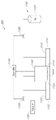
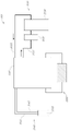
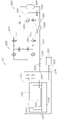
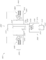
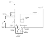
도 1은 본 발명의 다양한 실시 형태에 따른 가스 인클로저 시스템의 도면.
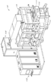
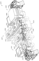
도 2는 본 발명의 다양한 실시 형태에 따른 가스 인클로저 시스템의 좌측 정면 사시도.
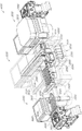
도 3은 본 발명의 다양한 실시 형태에 따른 가스 인클로저 시스템의 우측 정면 사시도.
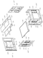
도 4는 본 발명의 다양한 실시 형태에 따른 가스 인클로저 시스템의 분해도.
도 5는 본 발명의 다양한 실시 형태에 따른 프레임 부재 조립체의 분해도.
도 6a 내지 도 6c는 조인트를 형성하기 위하여 개스킷 밀봉부의 다양한 실시 형태의 상면도.
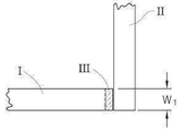
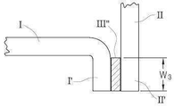
도 7a 및 도 7b는 본 발명의 다양한 실시 형태에 따른 가스 인클로저 시스템의 프레임 부재를 도시하는 도면.
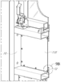
도 8a 및 도 8b는 본 발명의 가스 인클로저 시스템에 따른 용이제거가능 서비스 윈도우를 수용하기 위한 섹션 패널의 밀봉에 대한 다양한 도면을 도시하는 도면.
도 9a 및 도 9b는 본 발명에 따른 인셋 패널 또는 윈도우 패널을 수용하기 위한 섹션 패널의 밀봉에 대한 다양한 도면을 도시하는 도면.
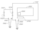
도 10은 본 발명에 따른 가스 인클로저 시스템의 다양한 실시 형태에 대한 라이팅 시스템을 포함하는 천장의 도면.
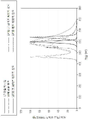
도 11은 본 발명에 따른 가스 인클로저 시스템의 다양한 실시 형태에 대한 라이팅 시스템의 LED 라이팅 스펙트럼을 도시하는 그래프.
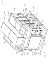
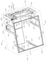
도 12는 본 발명의 다양한 실시 형태에 따른 가스 인클로저 조립체의 내부에 설치된 덕트워크를 도시하는 가스 인클로저 조립체의 정면 사시도.
도 13은 본 발명의 다양한 실시 형태에 따른 가스 인클로저 조립체의 내부에 설치된 덕트워크를 도시하는 가스 인클로저 조립체의 상면 사시도.
도 14는 본 발명의 다양한 실시 형태에 따른 가스 인클로저 조립체의 내부에 설치된 덕트워크를 도시하는 가스 인클로저 조립체의 저면 사시도.
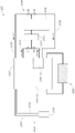
도 15는 본 발명의 다양한 실시 형태에 따른 가스 인클로저 시스템의 도면.
도 16은 본 발명의 다양한 실시 형태에 따른 가스 인클로저 시스템의 도면.
도 17은 본 발명의 다양한 실시 형태에 따른 가스 인클로저 시스템의 도면.
도 18은 본 발명의 다양한 실시 형태에 따른 가스 인클로저 시스템의 도면.
도 19는 본 발명의 다양한 실시 형태에 따른 가스 인클로저 시스템의 도면.
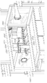
도 20a는 본 발명의 다양한 실시 형태에 따른 관련 프린팅 시스템 및 도 19에 도시된 가스 인클로저 시스템의 다양한 시스템의 분해도.
도 20b는 도 20a에 도시된 프린팅 시스템의 확대도.
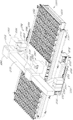
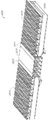
도 21은 본 발명의 다양한 실시 형태에 따른 부유 테이블의 사시도.
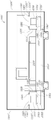
도 22a는 본 발명의 다양한 실시 형태에 따른 가스 인클로저 시스템의 단면도.
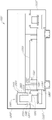
도 22b 및 도 22c는 본 발명의 다양한 실시 형태에 따른 가스 인클로저 시스템의 단면도.
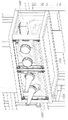
도 22d 내지 도 22f는 본 발명의 다양한 실시 형태에 따른 가스 인클로저 시스템의 단면도.
도 23은 본 발명의 다양한 실시 형태에 따른 가스 인클로저 시스템의 보조 인클로저 내에 장착된 관리 스테이션의 사시도.
도 24a 및 도 24b는 본 발명에 따른 시스템 및 방법의 다양한 실시 형태의 도면.
도 25는 본 발명의 다양한 실시 형태에 따른 가스 인클로저 조립체의 보조 인클로저의 사시도.
도 26a는 본 발명에 따른 시스템 및 방법의 다양한 실시 형태에 따른 OLED 프린팅 공구의 정면 사시도.
도 26b는 본 발명에 따른 시스템 및 방법의 다양한 실시 형태에 따른 OLED 프린팅 공구의 제1 정면 사시도.
도 27은 본 발명의 프린팅 시스템의 다양한 실시 형태에 따른 프린팅 시스템의 사시도.
도 28a는 본 발명에 따른 시스템 및 방법의 다양한 실시 형태에 따른 OLED 프린팅 공구의 정면 사시도.
도 28b는 본 발명에 따른 시스템 및 방법의 다양한 실시 형태에 따른 OLED 프린팅 공구의 평면도.
도 28c는 도 28a의 시스템 및 방법의 다양한 실시 형태에 따른 OLED 프린팅 공구의 평면도.
도 29a 내지 도 29c는 보조 인클로저를 포함한 본 발명의 가스 인클로저 시스템의 다양한 실시 형태의 평면도.
도 30a 내지 도 30c는 보조 인클로저를 포함한 본 발명의 가스 인클로저 시스템의 다양한 실시 형태의 평면도.A better understanding of the features and advantages of the present invention may be obtained by referring to the accompanying drawings, which are intended to illustrate, but not limit, the present invention.
1 is a diagram of a gas enclosure system according to various embodiments of the present invention;
2 is a left front perspective view of a gas enclosure system according to various embodiments of the present disclosure;
3 is a right front perspective view of a gas enclosure system according to various embodiments of the present disclosure;
4 is an exploded view of a gas enclosure system according to various embodiments of the present invention;
5 is an exploded view of a frame member assembly according to various embodiments of the present invention;
6A-6C are top views of various embodiments of a gasket seal to form a joint.
7A and 7B show a frame member of a gas enclosure system according to various embodiments of the present invention.
8a and 8b show various views of the sealing of a section panel for accommodating an easily removable service window according to the gas enclosure system of the present invention.
9a and 9b show various views of the sealing of a section panel for receiving an inset panel or window panel according to the present invention;
10 is a view of a ceiling including a lighting system for various embodiments of a gas enclosure system in accordance with the present invention.
11 is a graph depicting the LED lighting spectrum of a lighting system for various embodiments of a gas enclosure system in accordance with the present invention.
12 is a front perspective view of a gas enclosure assembly showing ductwork installed inside the gas enclosure assembly according to various embodiments of the present invention;
13 is a top perspective view of a gas enclosure assembly showing ductwork installed inside the gas enclosure assembly according to various embodiments of the present invention;
14 is a bottom perspective view of a gas enclosure assembly showing ductwork installed inside the gas enclosure assembly according to various embodiments of the present invention;
15 is a diagram of a gas enclosure system in accordance with various embodiments of the present invention.
16 is a diagram of a gas enclosure system in accordance with various embodiments of the present invention.
17 is a diagram of a gas enclosure system in accordance with various embodiments of the present invention.
18 is a diagram of a gas enclosure system in accordance with various embodiments of the present invention.
19 is a diagram of a gas enclosure system in accordance with various embodiments of the present invention.
20A is an exploded view of various systems of the gas enclosure system shown in FIG. 19 and related printing systems in accordance with various embodiments of the present invention.
FIG. 20B is an enlarged view of the printing system shown in FIG. 20A.
21 is a perspective view of a floating table according to various embodiments of the present invention;
22A is a cross-sectional view of a gas enclosure system in accordance with various embodiments of the present invention.
22b and 22c are cross-sectional views of a gas enclosure system according to various embodiments of the present invention.
22D-22F are cross-sectional views of gas enclosure systems in accordance with various embodiments of the present invention.
23 is a perspective view of a management station mounted within an auxiliary enclosure of a gas enclosure system in accordance with various embodiments of the present invention.
24A and 24B are diagrams of various embodiments of systems and methods in accordance with the present invention.
25 is a perspective view of an auxiliary enclosure of a gas enclosure assembly according to various embodiments of the present disclosure;
26A is a front perspective view of an OLED printing tool in accordance with various embodiments of systems and methods in accordance with the present invention.
26B is a first front perspective view of an OLED printing tool according to various embodiments of systems and methods in accordance with the present disclosure;
27 is a perspective view of a printing system according to various embodiments of the present invention;
28A is a front perspective view of an OLED printing tool in accordance with various embodiments of systems and methods in accordance with the present invention.
28B is a plan view of an OLED printing tool in accordance with various embodiments of systems and methods in accordance with the present invention.
28C is a top view of an OLED printing tool according to various embodiments of the system and method of FIG. 28A.
29A-29C are plan views of various embodiments of a gas enclosure system of the present invention including an auxiliary enclosure.
30A-30C are plan views of various embodiments of a gas enclosure system of the present invention including an auxiliary enclosure.
본 발명은 프린팅 시스템을 수용하기 위한 가스 인클로저 조립체를 포함할 수 있는 가스 인클로저, 즉 제2 부피를 형성하는 보조 인클로저와 제1 부피 또는 작동 부피를 형성할 수 있는 프린팅 시스템 인클로저를 가질 수 있는 시스템 및 방법의 다양한 실시 형태를 개시한다. 본 발명에 따라서, 가스 인클로저의 다양한 실시 형태는 가스 인클로저의 외부와 보조 인클로저 사이의 접근을 허용하는 개구 및 보조 인클로저와 프린팅 시스템 인클로저 사이의 접근을 허용하는 개구를 가질 수 있다. 가스 인클로저의 다양한 실시 형태에서, 개구는 밀봉가능하게 밀폐될 수 있다. 본 발명의 가스 인클로저의 다양한 실시 형태는 밀봉가능하게 밀폐될 수 있는 개구를 가질 수 있다. 본 발명에 따라서, 보조 인클로저는 예를 들어, 보조 인클로저와 프린팅 시스템 인클로저 사이의 접근을 허용하는 개구를 밀봉가능하게 밀폐함으로써 프린팅 시스템 인클로저로부터 격리될 수 있다.The present invention relates to a system that can have a gas enclosure that can include a gas enclosure assembly for housing a printing system, i.e., an auxiliary enclosure that forms a second volume and a printing system enclosure that can form a first or working volume, and Various embodiments of the method are disclosed. In accordance with the present invention, various embodiments of a gas enclosure may have an opening allowing access between the outside of the gas enclosure and the auxiliary enclosure and an opening allowing access between the auxiliary enclosure and the printing system enclosure. In various embodiments of the gas enclosure, the opening may be sealably closed. Various embodiments of the gas enclosure of the present invention may have an opening that can be sealably closed. In accordance with the present invention, the auxiliary enclosure may be isolated from the printing system enclosure, for example by sealably sealing an opening allowing access between the auxiliary enclosure and the printing system enclosure.
프린팅 시스템 인클로저로부터 보조 인클로저의 격리는 프린트헤드 조립체의 다양한 구성요소의 관리와 관련된 다양한 절차가 프린팅 공정의 최소한의 간섭 또는 간섭이 없는 상태에서 수행될 수 있도록 허용한다. 프린팅 시스템은 프린트헤드 조립체와 연계된 다양한 측정 및 관리 절차를 수행하기 위해 사용될 수 있는 프린트헤드 관리 시스템의 다양한 실시 형태를 포함할 수 있다. 프린트헤드 관리 시스템은 프린트헤드 내의 모든 노즐로부터 액적(drop) 부피, 속도 및 궤적의 측정뿐만 아니라 노즐 발사를 위한 체크와 같은 측정 임무, 및 프린트헤드 장치 또는 프린트헤드의 교체 및 휴지통 내로 그리고 프린트헤드를 통하여 잉크 공급으로부터 잉크를 주입함으로써 프린트헤드를 퍼징하고 프라이밍하며, 초과 잉크의 노즐 표면을 블로팅(blotting) 또는 와이핑(wiping)하는 관리 임무를 허용하는 몇몇 하위시스템으로 구성될 수 있다.Isolation of the auxiliary enclosure from the printing system enclosure allows various procedures related to management of the various components of the printhead assembly to be performed with minimal or no interference with the printing process. A printing system can include various embodiments of a printhead management system that can be used to perform various measurement and management procedures associated with a printhead assembly. The printhead management system provides measurement tasks such as measuring drop volume, velocity and trajectory from all nozzles within the printhead, as well as checking for nozzle firing, and replacing and replacing printhead devices or printheads, into and from the trash, and the printhead. It may consist of several subsystems that allow the maintenance tasks of purging and priming the printhead by injecting ink from the ink supply through and blotting or wiping the nozzle surfaces of excess ink.
따라서, 각각의 서브시스템은 본래 소모가능한 다양한 부분들을 가질 수 있고, 블로터 종이(blotter paper), 잉크, 및 폐기물 리저버(waste reservoir)를 교체하는 것과 같은 교체를 필요로 할 수 있다. 다양한 소모가능한 부분은 예를 들어, 핸들러를 사용하는 완자동 모드에서 삽입을 위하여 패키징될 수 있다. 비-제한적인 예시로서, 블로터 종이는 블로팅 모듈로 사용하기 위하여 쉽사리 삽입가능한 카트리지 형태로 패키징될 수 있다. 또 다른 비-제한적인 예시로서, 잉크는 프린팅 시스템에서 사용하기 위한 카트리지 형태뿐만 아니라 교체가능 리저버 내에 패키징될 수 있다. 폐기물 리저버의 다양한 실시 형태는 퍼지 용기 모듈(purge basin module)로 사용하기 위하여 쉽사리 삽입될 수 있는 카트리지 형태로 패키징될 수 있다. 추가로, 프린팅 시스템의 다양한 구성요소의 부분은 주기적 교체가 필요할 수 있다. 예를 들어, 각각의 프린트헤드 조립체는 약 1개 내지 약 60개의 프린트헤드 장치를 포함할 수 있고, 여기서 각각의 프린트헤드 장치는 각각의 프린트헤드 장치 내에 약 1개 내지 약 30개의 프린트헤드를 가질 수 있다. 이와 같이, 본 발명의 프린팅 시스템의 다양한 실시 형태는 약 1개 내지 약 1800개의 프린트헤드를 가질 수 있다. 프린팅 공정 중에, 예를 들어, 제한되지 않은 프린트헤드 또는 프린트헤드 장치의 교체의 적절한 관리가 요구될 수 있다. 프린트헤드 교체 모듈은 프린트헤드 조립체 내로 사용하기 위하여 쉽사리 삽입될 수 있는 프린트헤드 장치 또는 프린트헤드와 같은 부분을 가질 수 있다. 모든 노즐로부터의 액적 부피, 속도 및 궤적의 광학적 감지를 기초로 한 측정뿐만 아니라 노즐 발사를 위한 체크를 위해 사용되는 측정 시스템이 사용 이후에 주기적 교체를 필요로 할 수 있는 소스 및 디텍터(detector)를 가질 수 있다. 다양한 고도 사용 부분이 예를 들어, 핸들러를 사용하여 완자동 모드로 삽입을 위해 패키징될 수 있다. 이에 관해, 프린팅 시스템의 관리와 관련된 다양한 공정 단계가 프린팅 시스템 인클로저로부터 분리될 수 있는 보조 인클로저 내에서 수행될 수 있다. 프린트헤드 관리 절차와 연계된 모든 단계가 미립자 오염뿐만 아니라 다양한 유기 증기 및 공기와 수증기와 같은 오염에 대한 프린팅 시스템 인클로저의 노출을 배제 또는 최소화하기 위하여 수행될 수 있다. 본 발명의 다양한 시스템 및 방법에 따라서, 프린팅 시스템 인클로저는 프린팅 공정에 영향을 미치기 전에 정화 시스템이 오염물을 제거할 수 있기에 충분히 낮은 오염 수준으로 채택될 수 있다.Thus, each subsystem may have various parts that are inherently consumable and may require replacement, such as replacing blotter paper, ink, and waste reservoirs. Various consumable parts may be packaged for insertion in a fully automated mode using, for example, a handler. As a non-limiting example, blotter paper can be packaged in the form of an easily insertable cartridge for use as a blotting module. As another non-limiting example, ink may be packaged in a replaceable reservoir as well as in cartridge form for use in a printing system. Various embodiments of the waste reservoir can be packaged in the form of a cartridge that can be easily inserted for use as a purge basin module. Additionally, parts of the various components of the printing system may require periodic replacement. For example, each printhead assembly can include from about 1 to about 60 printhead devices, where each printhead device will have from about 1 to about 30 printheads in each printhead device. can As such, various embodiments of the printing system of the present invention may have from about 1 to about 1800 printheads. During the printing process, proper management may be required, for example and not limited to replacement of printheads or printhead devices. A printhead replacement module may have a printhead device or printhead-like part that can be readily inserted for use into a printhead assembly. The measurement system used for measurements based on optical sensing of droplet volume, velocity and trajectory from all nozzles as well as checking for nozzle firing eliminates sources and detectors that may require periodic replacement after use. can have Various highly used parts can be packaged for insertion in a fully automated mode using, for example, handlers. In this regard, various process steps associated with the management of the printing system may be performed in an auxiliary enclosure that may be separate from the printing system enclosure. All steps associated with printhead maintenance procedures can be performed to eliminate or minimize exposure of the printing system enclosure to contaminants such as particulate contamination as well as various organic vapors and air and water vapor. According to the various systems and methods of the present invention, the printing system enclosure may be adapted to a level of contamination low enough that the purification system can remove contaminants before they affect the printing process.
게다가, 비교적 작은 부피의 보조 인클로저가 제공됨에 따라, 보조 인클로저의 복원은 전체 프린팅 시스템 인클로저의 복원보다 상당히 더 적은 시간이 소요될 수 있다. 본 발명의 다양한 시스템 및 방법에 따라서, 보조 인클로저는 가스 인클로저 시스템의 인클로저 부피의 약 1% 이하일 수 있다. 본 발명의 다양한 시스템 및 방법에 따라서, 보조 인클로저는 가스 인클로저 시스템의 인클로저 부피의 약 2% 이하일 수 있다. 본 발명의 다양한 시스템 및 방법에 따라서, 보조 인클로저는 가스 인클로저 시스템의 인클로저 부피의 약 5% 이하일 수 있다. 본 발명의 다양한 시스템 및 방법에 따라서, 보조 인클로저는 가스 인클로저 시스템의 인클로저 부피의 약 10% 이하일 수 있다. 본 발명의 다양한 시스템 및 방법에 따라서, 보조 인클로저는 가스 인클로저 시스템의 인클로저 부피의 약 20% 이하일 수 있다.Additionally, given the relatively small volume of the auxiliary enclosure, restoration of the auxiliary enclosure may take significantly less time than restoration of the entire printing system enclosure. According to various systems and methods of the present invention, the auxiliary enclosure may be less than or equal to about 1% of the enclosure volume of the gas enclosure system. According to various systems and methods of the present invention, the auxiliary enclosure may be about 2% or less of the enclosure volume of the gas enclosure system. According to various systems and methods of the present invention, the auxiliary enclosure may be up to about 5% of the enclosure volume of the gas enclosure system. According to various systems and methods of the present invention, the auxiliary enclosure may be about 10% or less of the enclosure volume of the gas enclosure system. According to various systems and methods of the present invention, the auxiliary enclosure may be about 20% or less of the enclosure volume of the gas enclosure system.
보조 인클로저에 의해 형성된 제2 부피 및 프린팅 시스템 인클로저에 의해 형성된 제1 부피를 포함하는 가스 인클로저 시스템의 다양한 실시 형태는 라이팅, 가스 순환 및 여과, 가스 정화 및 가스 인클로저 시스템 내에서 유지되는 환경의 열 제어와 같은 다양한 환경적 파라미터의 환경적 제어를 포함할 수 있다. 가스 인클로저 시스템의 다양한 실시 형태는 제1 부피를 형성하는 프린팅 시스템 인클로저 및 제2 부피를 형성하는 보조 인클로저에 대한 균일한 제어 환경을 가질 수 있다. 가스 인클로저 시스템에 대한 이러한 균일한 제어 환경은 예를 들어, 불활성 환경뿐만 아니라 이러한 환경을 필요로 하는 공정에 대한 실질적으로 입자가 없는 환경을 제공할 수 있다. 대안으로, 가스 인클로저의 다양한 실시 형태는 보조 인클로저에 대해 유지되는 제어 환경과 상이한 조건 하에서 유지될 수 있는 가스 인클로저 시스템의 프린팅 시스템 인클로저 내에서 제어 환경을 제공할 수 있다.Various embodiments of a gas enclosure system including a second volume formed by the auxiliary enclosure and a first volume formed by the printing system enclosure provide lighting, gas circulation and filtration, gas purification, and thermal control of an environment maintained within the gas enclosure system. It may include environmental control of various environmental parameters such as Various embodiments of a gas enclosure system can have a uniform controlled environment for a printing system enclosure forming a first volume and an auxiliary enclosure forming a second volume. Such a uniform, controlled environment for a gas enclosure system can provide, for example, an inert environment as well as a substantially particle free environment for processes requiring such an environment. Alternatively, various embodiments of the gas enclosure may provide a controlled environment within the printing system enclosure of the gas enclosure system that may be maintained under different conditions than the controlled environment maintained for the auxiliary enclosure.
전술된 바와 같이, 가스 인클로저의 다양한 실시 형태는 가스 인클로저의 외부와 보조 인클로저 사이의 접근을 허용하는 개구 뿐만 아니라 보조 인클로저와 프린팅 시스템 인클로저 사이의 접근을 허용하는 통로 또는 밀봉가능 개구를 가질 수 있다. 따라서, 보조 인클로저의 다양한 실시 형태는 가스 인클로저 시스템의 프린팅 시스템 인클로저로부터 격리될 수 있고, 이에 따라 각각의 부피가 개별적으로 기능을 하는 섹션이다. 게다가, 프린팅 시스템 인클로저가 보조 인클로저로부터 격리되는 반면 가스 인클로저의 외부와 보조 인클로저 사이의 개구는 프린팅 시스템 인클로저 인클로저를 오염시키지 않고 주변 또는 비-불활성 공기로 개방될 수 있다. 가스 인클로저 시스템의 다양한 실시 형태의 경우, 밀봉가능 개구 또는 통로는 비-제한 예시로서 인클로저 패널 개구 또는 통로, 도어 또는 윈도우를 포함할 수 있다. 본 발명의 시스템 및 방법에 따라서, 밀봉가능 개구 또는 통로는 가스 인클로저의 외부 환경과 인클로저 또는 2개의 인클로저와 같이 2개의 부피 또는 격실 간의 접근을 허용할 수 있다. 본 발명에 따라서, 밀봉가능 개구가 밀봉방식으로 밀폐될 때, 하나 이상의 부피 또는 격실의 격리가 야기될 수 있다. 예를 들어, 본 발명의 다양한 실시 형태에서, 프린팅 시스템 인클로저는 보조 인클로저와 프린팅 시스템 인클로저 사이의 접근을 허용하는 개구 또는 통로를 밀봉방식으로 밀폐하기 위하여 구조적 밀폐부를 사용하여 보조 인클로저로부터 격리될 수 있다. 유사하게, 보조 인클로저는 보조 인클로저에 대한 환경과 보조 인클로저 사이의 접근을 허용하는 개구 또는 통로를 밀봉방식으로 밀폐하기 위하여 구조적 밀폐부를 사용함으로써 가스 인클로저의 외부로부터 격리될 수 있다. 하기에서 더욱 상세히 설명된 바와 같이, 구조적 밀폐부는 인클로저 패널 개구 또는 통로, 도어 또는 윈도우의 비-제한 예시를 포함하는 이러한 개구 또는 통로, 개구 또는 통로를 위한 다양한 밀봉가능 커버링을 포함할 수 있다. 본 발명의 시스템 및 방법에 따라서, 게이트가 공압, 유압, 전기식 또는 수동 조작을 사용하여 임의의 개구 또는 통로를 가역적으로 덮거나 또는 가역적으로 밀봉방식으로 밀폐하기 위해 사용될 수 있는 임의의 구조적 밀폐부일 수 있다.As noted above, various embodiments of the gas enclosure may have passages or sealable openings allowing access between the auxiliary enclosure and the printing system enclosure as well as openings allowing access between the exterior of the gas enclosure and the auxiliary enclosure. Thus, various embodiments of the auxiliary enclosure can be isolated from the printing system enclosure of the gas enclosure system, whereby each volume is an individually functioning section. Additionally, while the printing system enclosure is isolated from the auxiliary enclosure, the opening between the outside of the gas enclosure and the auxiliary enclosure can be opened to ambient or non-inert air without contaminating the printing system enclosure enclosure. For various embodiments of gas enclosure systems, sealable openings or passages may include, as non-limiting examples, enclosure panel openings or passages, doors or windows. According to the systems and methods of the present invention, a sealable opening or passageway may allow access between the external environment of a gas enclosure and two volumes or compartments, such as an enclosure or two enclosures. According to the present invention, when the sealable opening is hermetically closed, isolation of one or more volumes or compartments may result. For example, in various embodiments of the present invention, a printing system enclosure may be isolated from an auxiliary enclosure using a structural closure to hermetically seal an opening or passage allowing access between the auxiliary enclosure and the printing system enclosure. . Similarly, an auxiliary enclosure may be isolated from the exterior of a gas enclosure by using a structural seal to hermetically seal an opening or passage allowing access between the auxiliary enclosure and the environment to the auxiliary enclosure. As described in more detail below, structural closures may include various sealable coverings for such openings or passages, openings or passages, including non-limiting examples of enclosure panel openings or passages, doors or windows. According to the systems and methods of the present invention, a gate can be any structural closure that can be used to reversibly close or reversibly hermetically close any opening or passage using pneumatic, hydraulic, electrical or manual operation. have.
게다가, 동적 밀폐부의 사용은 산소, 수증기뿐만 아니라 유기 증기와 같은 반응 가스에 의해 오염으로부터 인클로저를 효과적으로 보호하고 개구 또는 통로를 밀봉방식으로 밀폐할 수 있다. 예를 들어, 본 발명의 다양한 실시 형태에서, 프린팅 시스템 인클로저는 프린팅 시스템 인클로저와 보조 인클로저 사이의 접근을 허용하는 개구 또는 통로를 효과적으로 밀봉방식으로 밀폐하기 위하여 동적 밀폐부를 사용함으로써 보조 인클로저로부터 격리될 수 있다. 유사하게, 보조 인클로저는 보조 인클로저 외부의 환경과 보조 인클로저 사이의 접근을 허용하는 개구 또는 통로를 효과적으로 밀봉방식으로 밀폐하기 위하여 동적 밀폐부를 사용함으로써 가스 인클로저의 외부로부터 격리될 수 있다. 본 발명에 따라서, 동적 밀폐부는 예를 들어, 가스 인클로저 시스템의 외부와 보조 인클로저와 프린팅 시스템 인클로저 사이의 개구 또는 통로에서 부피 또는 격실 사이에서 사용된 가스 커튼(gas curtain) 또는 압력 차이를 포함할 수 있다. 비-제한적인 예시로서, 프린팅 시스템 인클로저는 프린팅 시스템 인클로저 내로 비-불활성 가스의 역확산(back diffusion)을 방지하기 위하여 보조 인클로저와 프린팅 시스템 인클로저 사이의 개구 또는 통로에서 압력 차이를 사용함으로써 보조 인클로저로부터 동적으로 격리될 수 있다. 유사하게, 보조 인클로저는 보조 인클로저 내로 비-불활성 가스의 역확산을 방지하기 위하여 가스 인클로저의 외부와 보조 인클로저 사이의 개구 또는 통로에서 압력 차이를 이용함으로써 가스 인클로저의 외부로부터 동적으로 격리될 수 있다. 추가 비-제한적인 예시로서, 프린팅 시스템 인클로저는 보조 인클로저와 프린팅 시스템 인클로저 사이의 확산 배리어로서 효과적으로 기능을 할 수 있는 가스 커튼을 사용하여 보조 인클로저로부터 동적으로 격리될 수 있다. 유사하게, 보조 인클로저는 가스 인클로저의 외부와 보조 인클로저 사이의 확산 배리어로서 효과적으로 기능을 할 수 있는 가스 커튼을 사용하여 보조 인클로저의 외부로부터 동적으로 격리될 수 있다. In addition, the use of dynamic seals can effectively protect the enclosure from contamination by reactive gases such as oxygen, water vapor as well as organic vapors and hermetically seal openings or passages. For example, in various embodiments of the present invention, a printing system enclosure may be isolated from an auxiliary enclosure by using a dynamic seal to effectively seal off an opening or passage allowing access between the printing system enclosure and the auxiliary enclosure. have. Similarly, the auxiliary enclosure may be isolated from the exterior of the gas enclosure by using a dynamic seal to effectively seal off an opening or passageway allowing access between the auxiliary enclosure and the environment outside the auxiliary enclosure. In accordance with the present invention, dynamic seals may include used gas curtains or pressure differentials between volumes or compartments, for example at the exterior of the gas enclosure system and at openings or passages between the auxiliary enclosure and the printing system enclosure. have. As a non-limiting example, the printing system enclosure may be removed from the auxiliary enclosure by using a pressure differential in an opening or passageway between the auxiliary enclosure and the printing system enclosure to prevent back diffusion of non-inert gas into the printing system enclosure. can be dynamically isolated. Similarly, an auxiliary enclosure may be dynamically isolated from the exterior of the gas enclosure by using a pressure differential in an opening or passageway between the exterior of the gas enclosure and the auxiliary enclosure to prevent back-diffusion of the non-inert gas into the auxiliary enclosure. As a further non-limiting example, the printing system enclosure can be dynamically isolated from the auxiliary enclosure using a gas curtain that can effectively function as a diffusion barrier between the auxiliary enclosure and the printing system enclosure. Similarly, the auxiliary enclosure can be dynamically isolated from the outside of the auxiliary enclosure using a gas curtain that can effectively function as a diffusion barrier between the outside of the gas enclosure and the auxiliary enclosure.
가스 인클로저 시스템의 다양한 실시 형태의 경우, 개구 또는 통로는 구조적 밀폐부 및 동적 밀폐부의 다양한 실시 형태의 조합을 사용하여 밀봉방식으로 밀폐될 수 있다. 비-제한적인 예시로서, 프린팅 시스템 인클로저는 보조 인클로저와 프린팅 시스템 인클로저 사이의 접근을 허용하는 개구 또는 통로 사이에 가스 커튼 또는 압력 차이와 같이 동적 밀폐부와 조합하여 적합한 커버링을 사용하여 보조 인클로저로부터 격리될 수 있다. 유사하게 보조 인클로저는 가스 인클로저의 외부와 보조 인클로저 간의 접근을 허용하는 개구 또는 통로 사이의 가스 커튼 또는 압력 차이와 같은 동적 밀폐부와 조합하여 밀봉가능 커버링을 허용하여 가스 인클로저의 외부로부터 격리될 수 있다. 추가 비-제한적인 예시로서, 프린팅 시스템 인클로저는 보조 인클로저와 프린팅 시스템 인클로저 간의 접근을 허용하는 개구 또는 통로 사이의 적합한 커버링을 사용하여 보조 인클로저로부터 격리될 수 있고, 보조 인클로저는 가스 인클로저의 외부와 보조 인클로저 간의 접근을 허용하는 개구 또는 통로 사이의 가스 커튼 또는 압력 차이와 같이 동적 밀폐부를 사용하여 가스 인클로저의 외부로부터 격리될 수 있다.For various embodiments of a gas enclosure system, the opening or passageway may be hermetically sealed using a combination of various embodiments of structural closures and dynamic closures. As a non-limiting example, the printing system enclosure is isolated from the auxiliary enclosure using a suitable covering in combination with a dynamic seal, such as a gas curtain or pressure differential between the auxiliary enclosure and an opening or passage allowing access between the printing system enclosure. It can be. Similarly the auxiliary enclosure may be isolated from the exterior of the gas enclosure allowing for a sealable covering in combination with a dynamic seal such as a gas curtain or pressure differential between an opening or passage allowing access between the exterior of the gas enclosure and the auxiliary enclosure. . As a further non-limiting example, the printing system enclosure may be isolated from the auxiliary enclosure using a suitable covering between the opening or passageway allowing access between the auxiliary enclosure and the printing system enclosure, the auxiliary enclosure being connected to the outside of the gas enclosure and the auxiliary enclosure. It may be isolated from the outside of the gas enclosure using dynamic seals, such as gas curtains or pressure differentials between openings or passages that allow access between the enclosures.
본 발명의 다양한 실시 형태에 따라서, 가스 인클로저는 다양한 하우징일 수 있는 보조 인클로저를 가질 수 있다. 보조 인클로저의 다양한 실시 형태는 프린팅 시스템을 수용하기 위한 가스 인클로저 조립체의 섹션으로서 구성될 수 있다. 보조 인클로저의 다양한 실시 형태는 예를 들어, 적응형 제어-환경 인클로저, 이송 챔버, 및 로드 록 챔버(로드 록 챔버)일 수 있지만 이에 제한되지 않는다. 적응형 제어-환경 인클로저, 이송 챔버, 및 로드 록 챔버와 같은 보조 인클로저의 다양한 실시 형태는 일 위치로부터 또 다른 위치로 쉽사리 이동할 수 있다. 다양한 실시 형태에서, 보조 인클로저는 불활성 환경으로 유지될 수 있는 제2 부피를 형성할 수 있다. 본 발명의 가스 인클로저 시스템의 실시 형태의 경우, 제1 부피를 형성하는 프린팅 시스템을 수용하기 위한 가스 인클로저 조립체는 유기 용매 증기뿐만 아니라 수증기와 산소와 같은 다양한 반응성 주변 가스를 포함하는 다양한 반응종의 각각의 종에 대해 100 ppm 이하, 예를 들어, 10 ppm 이하, 1.0 ppm 이하. 또는 0.1 ppm 이하로 유지될 수 있는 가스 부피를 가질 수 있다. 추가로, 본 발명의 가스 인클로저 시스템의 경우 제2 부피를 형성하는 보조 인클로저는 유기 용매 증기뿐만 아니라 수증기와 산소와 같은 다양한 반응성 주변 가스를 포함하는 다양한 반응종의 각각의 종에 대해 100 ppm 이하, 예를 들어, 10 ppm 이하, 1.0 ppm 이하. 또는 0.1 ppm 이하로 유지될 수 있는 가스 부피를 가질 수 있다. 게다가, 가스 인클로저 시스템의 다양한 실시 형태는 문헌 [International Standards Organization Standard (ISO) 14644-1 :1999, "Cleanrooms and associated controlled environments-Part 1 : Classification of air cleanliness," as specified by Class 1 through Class 5]의 표준에 부합되는 저 입자 프린팅 환경을 제공할 수 있다.According to various embodiments of the present invention, a gas enclosure may have an auxiliary enclosure, which may be a variety of housings. Various embodiments of the auxiliary enclosure may be configured as a section of a gas enclosure assembly to house a printing system. Various embodiments of auxiliary enclosures can be, for example, but not limited to, adaptive controlled-environment enclosures, transport chambers, and load lock chambers (load lock chambers). Various embodiments of auxiliary enclosures such as adaptive controlled-environment enclosures, transfer chambers, and load lock chambers can be readily moved from one location to another. In various embodiments, the auxiliary enclosure can form a second volume that can be maintained as an inert environment. In the case of an embodiment of the gas enclosure system of the present invention, a gas enclosure assembly for housing a printing system forming a first volume may contain each of a variety of reactive species including organic solvent vapors as well as various reactive ambient gases such as water vapor and oxygen. 100 ppm or less, eg, 10 ppm or less, 1.0 ppm or less, for species of or a gas volume that can be maintained below 0.1 ppm. Additionally, in the case of the gas enclosure system of the present invention, the auxiliary enclosure forming the second volume contains less than 100 ppm for each species of various reactive species, including organic solvent vapors as well as various reactive ambient gases such as water vapor and oxygen; For example, 10 ppm or less, 1.0 ppm or less. or a gas volume that can be maintained below 0.1 ppm. Additionally, various embodiments of gas enclosure systems are described in International Standards Organization Standard (ISO) 14644-1 :1999, "Cleanrooms and associated controlled environments-Part 1 : Classification of air cleanliness," as specified by Class 1 through Class 5. It is possible to provide a low-particle printing environment that meets the standard of
앞에서 언급한 것과 같이, 약 130 cm x 150 cm의 치수를 가진 5.5 세대 기판보다 더 큰 기판 상에 OLED 디스플레이를 제작하는 것은 상당한 공학적 도전을 제시한다. 마더 글래스(mother glass) 기판 크기의 세대는 대략 1990년 초기 이래로 OLED 프린팅 외에 평판 디스플레이 용도로 진화하여 왔다. 1 세대로 지칭되는 마더 글래스 기판의 제1 세대는 약 30cm x 40cm이며, 따라서 15" 패널을 생산할 수 있다. 1990년 중반쯤에는, 평판 디스플레이를 제작하기 위한 기존의 기술은 약 60cm x 72cm 수치를 가지는 3.5 세대의 마더 글래스 기판 크기로 진화하였다. As mentioned earlier, fabricating OLED displays on substrates larger than Gen 5.5 substrates with dimensions of approximately 130 cm x 150 cm present significant engineering challenges. A generation of mother glass substrate sizes has evolved since about the early 1990s for flat panel display applications other than OLED printing. The first generation of mother glass substrates, referred to as generation 1, is about 30 cm x 40 cm, and thus can produce 15" panels. By the mid-1990s, existing technology for fabricating flat panel displays had dimensions of about 60 cm x 72 cm. Eggplant has evolved to the size of the mother glass substrate of the 3.5th generation.
세대가 진화해갈 때, OLED 프린팅 제작 공정 외의 용도를 위해 7.5 세대 및 8.5 세대를 위한 마더 글래스 크기가 생산 중이다. 7.5 세대 마더 글래스는 약 195cm x 225 cm의 수치를 가지며, 기판 당 8개의 42" 또는 6개의 47" 평판으로 절단될 수 있다. 8.5 세대에 사용되는 마더 글래스는 거의 220 x 250 cm이며, 기판 당 6개의 55" 또는 8개의 46" 평판으로 절단될 수 있다. OLED 평판 디스플레이 품질은 트루 칼라, 고선명, 박막, 가요성, 투명도, 및 에너지 효율이 구현되는 동시에, 실제로 OLED 제작은 3.5 세대 및 그보다 더 작은 크기에 제한된다. 현재, OLED 프린팅은 이러한 제약을 깨뜨리고 3.5 세대 및 그보다 작은 마더 글래스 크기뿐만 아니라 가장 큰 마더 글래스 크기, 예컨대, 5.5 세대, 7.5 세대, 및 8.5 세대를 위해 OLED 패널을 제작할 수 있게 하는 최적의 제작 기술이라고 믿어진다. 당업자는 OLED 패널 프린팅의 특징들 중 한 특징으로, 다양한 기판 재료, 이들에만 제한되지는 않지만, 예컨대, 예를 들어, 다양한 유리 기판 재료, 뿐만 아니라 다양한 중합체 기판 재료들이 사용되는 것을 이해할 수 있을 것이다. 이런 점에서, 유리-기반의 기판을 사용하는 데에서 기인하는 크기는 OLED 프린팅에 사용하기에 적합한 임의의 재료의 기판에 제공될 수 있다. As generations evolve, mother glass sizes for Gen 7.5 and Gen 8.5 are in production for uses outside of the OLED printing manufacturing process. Gen 7.5 mother glass measures approximately 195 cm x 225 cm and can be cut into eight 42" or six 47" plates per substrate. The mother glass used in Gen 8.5 measures approximately 220 x 250 cm and can be cut into six 55" or eight 46" plates per substrate. OLED flat panel display quality is true color, high definition, thin film, flexibility, transparency, and energy efficiency, while in practice OLED production is limited to 3.5G and smaller sizes. Currently, OLED printing is said to be an optimal fabrication technology that breaks these constraints and enables OLED panels to be fabricated not only for 3.5G and smaller mother glass sizes, but also for the largest mother glass sizes, such as 5.5G, 7.5G, and 8.5G. It is believed. A person skilled in the art will appreciate that, as one of the features of OLED panel printing, various substrate materials are used, such as, but not limited to, various glass substrate materials, as well as various polymer substrate materials, for example. In this regard, the dimensions resulting from the use of glass-based substrates can be provided for substrates of any material suitable for use in OLED printing.
다양한 제제가 본 발명의 가스 인클로저 시스템의 다양한 실시 형태의 불활성의 실질적으로 입자가 없는 환경 내에서 인쇄될 수 있다. OLED 기판의 EL(emissive layer)의 프린팅을 위한 다양한 잉크 제제에 추가로, 다양한 잉크 제제는 하나 이상의 홀 이송 층(HTL), 홀 주입 층(HIL), 전자 이송 층(ETL), 및 OLED 장치의 전자 주입 층(EIL)을 형성하는데 유용한 하나 이상의 성분을 포함하는 잉크를 포함할 수 있다. A variety of formulations can be printed within the inert, substantially particle-free environment of various embodiments of the gas enclosure system of the present invention. In addition to various ink formulations for printing of emissive layers (ELs) of OLED substrates, various ink formulations may include one or more of a hole transport layer (HTL), a hole injection layer (HIL), an electron transport layer (ETL), and an OLED device. It may include an ink comprising one or more components useful for forming an electron injection layer (EIL).
추가로 유기 캡슐화 층은 잉크젯 프린팅을 사용하여 OLED 패널 상에 프린팅될 수 있다. 우선, 소정 범위의 진공 처리 작업이 이러한 잉크젯-기반 제조가 대기 압력에서 수행될 수 있기 때문에 생략될 수 있다. 추가로, 잉크젯 프린팅 공정 중에, 유기 캡슐화 층은 활성 영역의 횡방향 에지를 포함하는, 활성 영역을 효과적으로 캡슐화하기 위하여 활성 영역에 근접하게 그리고 이에 걸쳐 OLED 기판의 일부를 덮도록 국부화될 수 있다. 잉크젯 프린팅을 사용하여 목표 패터닝은 전형적으로 유기 층의 패터닝을 구현하기 위해 필요한 추가 공정이 배제될 뿐만 아니라 재료 폐기물을 제거한다. 캡슐화 잉크는 아크릴레이트, 메타크릴레이트, 우레탄, 또는 다른 재료뿐만 아니라 열 처리(예를 들어, 베이크), UV 노출, 및 이의 조합을 사용하여 경화될 수 있는 공중합체 및 이의 혼합물을 포함하지만 이에 제한되지 않는 중합체를 포함할 수 있다.Additionally the organic encapsulation layer can be printed on the OLED panel using inkjet printing. First of all, a range of vacuum processing operations can be omitted since such inkjet-based fabrication can be performed at atmospheric pressure. Additionally, during the inkjet printing process, the organic encapsulation layer can be localized to cover a portion of the OLED substrate proximate to and across the active area to effectively encapsulate the active area, including the lateral edges of the active area. Target patterning using inkjet printing eliminates material waste as well as eliminates the additional processing typically required to implement patterning of organic layers. Encapsulating inks include, but are not limited to, acrylates, methacrylates, urethanes, or other materials, as well as copolymers and mixtures thereof that can be cured using heat treatment (eg, bake), UV exposure, and combinations thereof. It may contain polymers that do not
OLED 프린팅에 관해, 본 발명에 따르면, 요구 수명 기준(requisite lifetime specification)을 충족시키는 OLED 평판 디스플레이를 제공하는데 상호관련을 위하여, 반응종, 예를 들어, 이들에만 제한되지는 않지만, 대기 성분, 예컨대, 산소 및 수증기, 뿐만 아니라 OLED 잉크에 사용되는 다양한 유기용매 증기의 레벨을 실질적으로 낮게 유지하는 방법이 밝혀졌다. 상기 요구 수명 기준은 특히 OLED 패널 기술의 용도로 상당한 의미를 가지며, 이것이 디스플레이 생산 수명, 및 모든 패널 기술에 대한 생산 기준에 직접적으로 상호관련이 있고, 현재의 OLED 패널 기술이 충족해야 하는 기준에 위험요소가 되고 있다. 요구 수명 기준을 충족하는 패널을 제공하기 위하여, 본 발명의 가스 인클로저 조립체 시스템의 여러 실시 형태들을 이용하면, 반응종, 예컨대, 수증기, 산소, 뿐만 아니라 유기용매 증기 각각의 레벨이 100 ppm 또는 그 이하, 예를 들어, 10 ppm 또는 그 이하, 1.0 ppm 또는 그 이하, 또는 0.1 ppm 또는 그 이하에 유지될 수 있다. 그 외에도, OLED 프린팅은 실질적으로 입자-없는 환경을 필요로 한다. OLED 프린팅을 위해 실질적으로 입자-없는 환경을 유지하는 것은 특히 중요한데, 심지어 매우 작은 입자라도 OLED 패널에 가시적인 결함을 야기할 수 있기 때문이다. 현재, OLED 디스플레이에 대해서 상용화를 위해 매우 낮은 결함 레벨을 충족시키는 것이 매우 어렵다. 전체 인클로저 시스템 내에 실질적으로 입자-없는 환경을 유지하는 것은 대기 상태, 예컨대, 야외(open air)의 고-유동 층류(high flow 층류) 여과 후드 하에서 수행될 수 있는 공정에 대해 입자를 감소시킴으로써 나타나지 않는 추가적인 위험요소를 제공한다. 이에 따라, 대형 설비 내에 불활성의, 입자-없는 환경을 위한 요구 기준을 유지하는 것은 또 다른 다양한 위험요소를 내포할 수 있다. Regarding OLED printing, according to the present invention, in order to correlate to providing an OLED flat panel display that meets the requisite lifetime specification, reactive species such as, but not limited to, atmospheric components such as , oxygen and water vapor, as well as a method for keeping the levels of various organic solvent vapors used in OLED inks substantially low. The above required life criteria have significant implications, especially for the use of OLED panel technology, as they directly correlate to the display production life, and production criteria for all panel technologies, and to the criteria that current OLED panel technologies must meet. becoming an element. Various embodiments of the gas enclosure assembly system of the present invention may be used to provide a panel that meets the required life criteria, wherein levels of reactive species, such as water vapor, oxygen, as well as organic solvent vapors, respectively, are 100 ppm or less. , for example, 10 ppm or less, 1.0 ppm or less, or 0.1 ppm or less. Besides that, OLED printing requires a substantially particle-free environment. Maintaining a substantially particle-free environment for OLED printing is particularly important, as even very small particles can cause visible defects in OLED panels. Currently, it is very difficult to meet very low defect levels for commercialization for OLED displays. Maintaining a substantially particle-free environment within the overall enclosure system is not manifested by particle reduction for processes that can be performed under atmospheric conditions, eg, open air, high-flow laminar flow filtration hoods. It presents an additional risk factor. Accordingly, maintaining the required standards for an inert, particle-free environment within a large facility may present a number of other hazards.
반응종, 예컨대, 수증기, 산소, 뿐만 아니라 유기용매 증기 각각의 레벨이 100 ppm 또는 그 이하, 예를 들어, 10 ppm 또는 그 이하, 1.0 ppm 또는 그 이하, 또는 0.1 ppm 또는 그 이하에 유지될 수 있는 설비 내에 OLED 패널을 프린팅하기 위한 필요성은 표 1에 요약된 정보를 검토함으로써 예시될 수 있다. 큰-픽셀(pixel)의 스핀-코팅된(spin-coated) 장치 포맷에서 제작된, 레드, 그린, 및 블루 각각에 대한 유기 박막 필름 조성물을 포함하는 테스트 쿠폰(test coupon)을 각각 테스트함으로써, 표 1에 요약된 데이터를 얻었다. 이러한 테스트 쿠폰은 다양한 조성 및 공정을 신속하게 평가하기 위하여 테스트하고 제작하기에 실질적으로 용이하다. 테스트 쿠폰 테스트가 프린팅 패널의 수명 테스트와 혼동되어서는 안 되지만, 수명에 끼치는 다양한 조성 및 공정의 영향을 가리키는 것일 수 있다. 밑의 표에 도시된 결과는, 오직 스핀-코팅 환경(spin-coating environment)이 질소 환경에서 제작된 테스트 쿠폰에 대해 변경되며, 반응종은 질소 환경(nitrogen environment) 대신에 공기(air)에서 비슷하게 제작된 테스트 쿠폰에 비해 1 ppm 미만인 테스트 쿠폰의 제작에 있어 공정 단계에서의 변경을 보여준다. Levels of reactive species, such as water vapor, oxygen, as well as organic solvent vapors, respectively, may be maintained at 100 ppm or less, such as 10 ppm or less, 1.0 ppm or less, or 0.1 ppm or less. The need to print OLED panels in existing facilities can be illustrated by reviewing the information summarized in Table 1. By testing each of the test coupons containing organic thin film compositions for each of red, green, and blue fabricated in a large-pixel spin-coated device format, The data summarized in 1 were obtained. These test coupons are substantially easier to test and fabricate for rapid evaluation of various formulations and processes. Test Coupon testing should not be confused with life testing of printed panels, but may refer to the effects of various formulations and processes on life. The results shown in the table below show that only the spin-coating environment is changed for test coupons fabricated in a nitrogen environment, and the reactive species are similar in air instead of a nitrogen environment. It shows changes in process steps in the fabrication of test coupons that are less than 1 ppm compared to fabricated test coupons.
서로 다른 처리 환경 하에서, 특히, 레드 및 블루 경우에서, 제작된 테스트 쿠폰에 대해 표 1의 데이터를 검사함으로써, 유기 박막 필름 조성이 반응종에 노출되는 것을 효율적으로 감소시키는 환경에서 프린팅은 다양한 ELM의 안정성에 실질적인 영향을 끼치고 이에 따라 수명에 영향을 끼칠 수 있음은 자명하다. By examining the data in Table 1 for fabricated test coupons under different processing environments, particularly in the red and blue cases, printing can be performed in environments that effectively reduce the exposure of the organic thin film composition to reactive species. It is clear that this can have a substantial impact on stability and thus life span.

추가로, 전술된 바와 같이, OLED 프린팅을 위한 실질적으로 입자가 없는 환경을 유지하는 것은 특히 중요하며, 이는 작은 입자가 OLED 패널 상에 가시 결함을 야기할 수 있기 때문이다. 현재, 설비는 충분히 저-입자 환경을 유지할 뿐만 아니라 유기 용매 증기와 수증기, 산소와 같이 각각의 반응종의 저 수준을 유지하기 위하여 상업화를 위한 필요 저결함 수준에 부합되는 OLED 디스플레이를 제조하기 위한 노력이 있다. 추가로, 이러한 가스 인클로저 시스템은, 예를 들어, 이들에만 제한되지는 않지만, 최소화된 불활성 가스 부피를 제공하면서도 OLED 프린팅 시스템을 위해 최적화된 작업 공간을 제공하며, 중지시간을 최소로 하면서 관리를 위해 내부에 접근을 제공하면서도 처리 작업 동안 외부로부터 OLED 프린팅 시스템에 쉽게 접근하도록 쉽게 스케일링될 수 있는 가스 인클로저를 포함하는 속성을 가지는 것으로 고려된다. 이에 따라, 본 발명의 다양한 실시 형태에 따라서, Additionally, as mentioned above, maintaining a substantially particle-free environment for OLED printing is particularly important, as small particles can cause visible defects on OLED panels. Currently, facilities strive to manufacture OLED displays that meet the low-defect levels required for commercialization in order to not only maintain a sufficiently low-particle environment, but also to maintain low levels of each reactive species such as organic solvent vapor, water vapor, and oxygen. there is Additionally, these gas enclosure systems provide, for example but not limited to, an optimized workspace for an OLED printing system while providing a minimized inert gas volume, and for maintenance with minimal downtime. It is contemplated to have a property that includes a gas enclosure that can be easily scaled to easily access the OLED printing system from the outside during processing operations while still providing access to the interior. Accordingly, according to various embodiments of the present invention,
불활성 환경(inert environment)을 필요로 하는 다양한 공기-민감성 공정(air-sensitive process)을 위한 가스 인클로저 조립체가 제공되는데, 상기 가스 인클로저 조립체는 함께 밀봉될 수 있는 복수의 벽 프레임 및 천장 프레임 부재를 포함할 수 있다. 몇몇 실시 형태들에서, 복수의 벽 프레임 및 천장 프레임 부재는 재사용 패스너(reusable fastener), 예를 들어, 볼트 및 스레드형 홀(threaded hole)을 이용하여 함께 고정될 수 있다. 본 발명에 따른 가스 인클로저 조립체의 여러 실시 형태들에 대해서, 복수의 프레임 부재는 가스 인클로저 프레임 조립체를 형성하도록 구성될 수 있으며, 각각의 프레임 부재는 복수의 패널 프레임 섹션을 포함한다. A gas enclosure assembly for various air-sensitive processes requiring an inert environment is provided, the gas enclosure assembly comprising a plurality of wall frame and ceiling frame members that can be sealed together. can do. In some embodiments, a plurality of wall frame and ceiling frame members may be secured together using reusable fasteners, such as bolts and threaded holes. For various embodiments of a gas enclosure assembly according to the present invention, a plurality of frame members may be configured to form a gas enclosure frame assembly, each frame member including a plurality of panel frame sections.
본 발명의 가스 인클로저 조립체가 시스템 주위에서 인클로저의 부피를 최소화할 수 있는 방식으로 시스템, 예컨대, OLED 프린팅 시스템을 수용하도록 설계될 수 있다. 가스 인클로저 조립체의 다양한 실시 형태는 가스 인클로저 조립체의 내부 부피를 최소화하면서도 이와 동시에 다양한 OLED 프린팅 시스템의 여러 풋프린트(footprint)를 수용하기 위해 작업 공간을 최적화하는 방식으로 구성될 수 있다. 예를 들어, 본 발명의 가스 인클로저 시스템의 다양한 실시 형태에 따른 OLED 프린팅 시스템은 예를 들어, 그래니트 베이스, OLED 프린팅 장치를 지지할 수 있는 이동식 브리지, 가압된 불활성 가스 재순환 시스템의 다양한 실시 형태로부터 이어지는 하나 이상의 장치, 예컨대 기판 부유 테이블, 에어 베어링, 트랙, 레일, OLED 잉크 공급 서브시스템 및 잉크젯 프린트헤드, 하나 이상의 로봇 등을 포함하는, 기판 상으로 OLED 필름 형성 재료를 증착하기 위한 잉크젯 프린터 시스템을 포함할 수 있다. OLED 프린팅 시스템을 포함할 수 있는 다양한 구성요소가 제시됨에 따라, OLED 프린팅 시스템의 다양한 실시 형태가 다양한 풋프린트 및 폼 팩터를 가질 수 있다. 이렇게 구성된 가스 인클로저 조립체의 다양한 실시 형태는 처리 공정 동안 외부로부터 가스 인클로저 조립체의 내부에 용이하게 접근할 수 있게 하고 중지시간을 최소화시키면서도 관리를 위해 내부에 용이하게 접근할 수 있게 하는 접근성을 추가로 제공한다. 이런 점에서, 본 발명에 따른 가스 인클로저 조립체의 다양한 실시 형태는 다양한 OLED 프린팅 시스템의 여러 풋프린트에 대해 윤곽이 형성될 수 있다(contoured). 다양한 실시 형태에 따르면, 일단 윤곽이 형성된 프레임 부재가 가스 인클로저 조립체를 형성하도록 구성되고 나면, 다양한 타입의 패널이 가스 인클로저 조립체의 설치 작업을 완료하기 위해 프레임 부재를 포함하는 복수의 패널 섹션 내에 밀봉 가능하게 설치될 수 있다. 가스 인클로저 조립체의 다양한 실시 형태에서, 복수의 프레임 부재, 예컨대, 예를 들어, 이들에만 제한되지는 않지만, 복수의 벽 프레임 부재 및 하나 이상의 천장 프레임 부재, 뿐만 아니라 패널 프레임 섹션 내에 설치하기 위한 복수의 패널이 한 위치 또는 여러 위치들에서 제작될 수 있으며 또 다른 장소에서도 제작될 수 있다. 게다가, 본 발명의 가스 인클로저 조립체를 형성하도록 사용된 구성요소들이 이동가능한 성질을 고려해 볼 때, 가스 인클로저 조립체의 다양한 실시 형태는 제작 및 해체 사이클을 통해 반복적으로 설치되고 제거될 수도 있다. A gas enclosure assembly of the present invention can be designed to accommodate a system, such as an OLED printing system, in a manner that can minimize the volume of the enclosure around the system. Various embodiments of the gas enclosure assembly can be configured in a manner that minimizes the internal volume of the gas enclosure assembly while at the same time optimizing the working space to accommodate the different footprints of various OLED printing systems. For example, an OLED printing system according to various embodiments of a gas enclosure system of the present invention may be obtained from, for example, various embodiments of a granite base, a movable bridge capable of supporting an OLED printing device, and a pressurized inert gas recirculation system. An inkjet printer system for depositing an OLED film forming material onto a substrate comprising one or more devices followed by a substrate floatation table, air bearings, tracks, rails, an OLED ink supply subsystem and an inkjet printhead, one or more robots, and the like. can include Given the various components that may comprise an OLED printing system, various embodiments of an OLED printing system may have a variety of footprints and form factors. Various embodiments of the gas enclosure assembly thus configured provide additional accessibility that facilitates access to the interior of the gas enclosure assembly from the outside during processing processes and facilitates access to the interior for maintenance while minimizing downtime. do. In this regard, various embodiments of gas enclosure assemblies according to the present invention can be contoured to the different footprints of various OLED printing systems. According to various embodiments, once the contoured frame members are configured to form a gas enclosure assembly, various types of panels can be sealed within a plurality of panel sections comprising the frame members to complete the installation of the gas enclosure assembly. can be installed appropriately. In various embodiments of a gas enclosure assembly, a plurality of frame members, such as, for example, but not limited to, a plurality of wall frame members and one or more ceiling frame members, as well as a plurality of frames for installation within a panel frame section. A panel may be fabricated at one location or several locations and may be fabricated at another location. Additionally, given the movable nature of the components used to form the gas enclosure assembly of the present invention, various embodiments of the gas enclosure assembly may be repeatedly installed and removed through cycles of fabrication and disassembly.
게다가, 보조 인클로저의 다양한 실시 형태는 가스 인클로저의 외부와 보조 인클로저 또는 프린팅 시스템 인클로저와 보조 인클로저 간의 접근을 허용하기 위하여 사용될 수 있는 밀봉가능 개구에 대해 구조적 밀폐부를 사용함으로써 또는 가스 인클로저의 외부로부터 가스 인클로저 시스템의 프린팅 시스템 인클로저의 작동 부피로부터 격리될 수 있다. 본 발명의 시스템 및 방법에 따라서, 구조적 밀폐부는 개구 또는 통로에 대한 다양한 밀봉가능 커버링을 포함할 수 있지만, 이러한 개구 또는 통로는 인클로저 패널 개구 또는 통로, 도어 또는 윈도우의 비제한적인 예시를 포함한다. 본 발명의 시스템 및 방법에 따라서, 게이트가 공압, 유압, 전기식 또는 수동 조작을 사용하여 임의의 개구 또는 통로를 가역적으로 덮거나 또는 가역적으로 밀봉방식으로 밀폐하기 위해 사용될 수 있는 임의의 구조적 밀폐부일 수 있다. 보조 인클로저의 다양한 실시 형태는 가스 인클로저의 외부와 보조 인클로저 간의 개구에서 또는 보조 인클로저와 가스 인클로저 시스템의 작동 부피 사이의 개구에서 압력 차이 또는 가스 커튼과 같은 동적 밀폐부를 사용하여 또는 가스 인클로저의 외부로부터 또는 프린팅 시스템 인클로저의 작동 부피로부터 격리될 수 있다. 가스 인클로저 시스템의 다양한 실시 형태의 경우, 보조 인클로저는 동적 밀폐부 및 구조적 밀폐부의 다양한 실시 형태의 조합을 사용하거나 또는 가스 인클로저의 외부로부터 프린팅 시스템 인클로저의 작동 부피로부터 격리될 수 있다.Additionally, various embodiments of the auxiliary enclosure can be used to allow access between the outside of the gas enclosure and the auxiliary enclosure or between the printing system enclosure and the auxiliary enclosure by using a structural seal to the sealable opening or from the outside of the gas enclosure. The system may be isolated from the working volume of the printing system enclosure. In accordance with the systems and methods of the present invention, structural seals may include a variety of sealable coverings for openings or passageways, although such openings or passageways include, but are not limited to, enclosure panel openings or passageways, doors or windows. According to the systems and methods of the present invention, a gate can be any structural closure that can be used to reversibly close or reversibly hermetically close any opening or passage using pneumatic, hydraulic, electrical or manual operation. have. Various embodiments of the auxiliary enclosure use a dynamic seal, such as a pressure difference or gas curtain, at an opening between the outside of the gas enclosure and the auxiliary enclosure, or at an opening between the auxiliary enclosure and the working volume of the gas enclosure system, or from the outside of the gas enclosure or It may be isolated from the working volume of the printing system enclosure. For various embodiments of the gas enclosure system, the auxiliary enclosure may be isolated from the working volume of the printing system enclosure from the outside of the gas enclosure or using a combination of various embodiments of a dynamic seal and a structural seal.
본 발명의 다양한 시스템 및 방법에 따라서, 보조 인클로저는 가스 인클로저 시스템의 인클로저 부피의 약 1% 이하일 수 있다. 본 발명의 다양한 시스템 및 방법에 따라서, 보조 인클로저는 가스 인클로저 시스템의 인클로저 부피의 약 2% 이하일 수 있다. 본 발명의 다양한 시스템 및 방법에 따라서, 보조 인클로저는 가스 인클로저 시스템의 인클로저 부피의 약 5% 이하일 수 있다. 본 발명의 다양한 시스템 및 방법에 따라서, 보조 인클로저는 가스 인클로저 시스템의 인클로저 부피의 약 10% 이하일 수 있다. 본 발명의 다양한 시스템 및 방법에 따라서, 보조 인클로저는 가스 인클로저 시스템의 인클로저 부피의 약 20% 이하일 수 있다. 이와 같이, 비교적 작은 부피의 보조 인클로저가 제시됨에 따라, 보조 인클로저의 복원은 전체 프린팅 시스템 인클로저의 복원보다 상당히 적은 시간이 소요될 수 있다. 따라서, 프린트헤드 관리 절차를 수행하면서 보조 인클로저를 이용하는 것은 가스 인클로저 시스템 중지시간을 최소화 또는 배제할 수 있다.According to various systems and methods of the present invention, the auxiliary enclosure may be less than or equal to about 1% of the enclosure volume of the gas enclosure system. According to various systems and methods of the present invention, the auxiliary enclosure may be about 2% or less of the enclosure volume of the gas enclosure system. According to various systems and methods of the present invention, the auxiliary enclosure may be up to about 5% of the enclosure volume of the gas enclosure system. According to various systems and methods of the present invention, the auxiliary enclosure may be about 10% or less of the enclosure volume of the gas enclosure system. According to various systems and methods of the present invention, the auxiliary enclosure may be about 20% or less of the enclosure volume of the gas enclosure system. As such, given the relatively small volume of the auxiliary enclosure, restoration of the auxiliary enclosure may take significantly less time than restoration of the entire printing system enclosure. Thus, using an auxiliary enclosure while performing printhead management procedures can minimize or eliminate gas enclosure system downtime.
가스 인클로저가 밀폐 방식으로 밀봉될 수 있도록 보장하기 위하여, 본 발명의 가스 인클로저 조립체의 다양한 실시 형태는 프레임 밀봉을 제공하기 위해 각각의 프레임 부재를 결합하도록 제공된다. 내부는 개스킷 또는 그 외의 다른 씰을 포함하는 여러 프레임 부재들 사이의 교차면들을 타이트하게 끼워맞춤으로써(tight-fitting) 충분히 밀봉될 수 있으며, 예컨대, 예를 들어, 밀폐 방식으로 밀봉될 수 있다. 완전히 구성되고 나면, 밀봉된 가스 인클로저 조립체가 내부 및 복수의 내부 코너 에지, 인접한 프레임 부재와 각각의 프레임 부재의 교차면에 제공된 하나 이상의 내부 코너 에지를 포함할 수 있다. 하나 또는 그 이상의 프레임 부재, 예컨대, 예를 들어, 프레임 부재의 적어도 절반은 하나 또는 그 이상의 각각의 에지를 따라 고정된 하나 또는 그 이상의 압축성 개스킷을 포함할 수 있다. 하나 또는 그 이상의 압축성 개스킷은, 복수의 프레임 부재가 함께 결합되고 가스가 새지 않는(gas-tight) 패널이 설치되고 나면, 밀폐 방식으로 밀봉된 가스 인클로저 조립체를 생성하도록 구성될 수 있다. 밀봉된 가스 인클로저 조립체가 복수의 압축성 개스킷에 의해 밀봉된 프레임 부재의 코너 에지를 가진 채로 형성될 수도 있다. 각각의 프레임 부재에 대해, 예를 들어, 이들에만 제한되지는 않지만, 내부 벽 프레임 표면, 상부 벽 프레임 표면, 수직면 벽 프레임 표면, 바닥 벽 프레임 표면, 및 이들의 조합에는 하나 또는 그 이상의 압축성 개스킷이 제공될 수도 있다. To ensure that a gas enclosure can be hermetically sealed, various embodiments of gas enclosure assemblies of the present invention provide for joining individual frame members to provide a frame seal. The interior may be sufficiently sealed, eg, in an airtight manner, by tight-fitting the intersections between the various frame members, including gaskets or other seals. Once fully constructed, the sealed gas enclosure assembly may include an interior and a plurality of interior corner edges, one or more interior corner edges provided at an intersection of each frame member with an adjacent frame member. One or more frame members, such as, for example, at least half of the frame members may include one or more compressible gaskets secured along respective edges of the one or more frame members. One or more compressible gaskets may be configured to create a hermetically sealed gas enclosure assembly once a plurality of frame members are joined together and gas-tight panels are installed. A sealed gas enclosure assembly may be formed with corner edges of frame members sealed by a plurality of compressible gaskets. For each framing member, one or more compressible gaskets may be present on, for example but not limited to, an inner wall framing surface, an upper wall framing surface, a vertical wall framing surface, a bottom wall framing surface, and combinations thereof. may be provided.
가스 인클로저 조립체의 다양한 실시 형태에 대해, 각각의 프레임 부재는 각각의 패널에 가스가 새지 않는 패널 씰을 제공하기 위해 각각의 섹션에 밀봉 가능하게 설치될 수 있는 다양한 패널 타입 중 임의의 타입의 패널을 수용하도록 제작되고 구성된 복수의 섹션을 포함할 수 있다. 본 발명의 가스 인클로저 조립체의 다양한 실시 형태에서, 각각의 섹션 프레임은, 선택된 패스너들로, 각각의 섹션 프레임 내에 설치된 각각의 패널이 각각의 패널에 대해 가스가 새지 않는 씰을 제공할 수 있으며 이에 따라 완전히 형성된 가스 인클로저에 대해 가스가 새지 않는 씰을 제공할 수 있는 섹션 프레임 개스킷을 가질 수 있다. 다양한 실시 형태에서, 한 가스 인클로저 조립체가 각각의 벽 패널 내에 하나 또는 그 이상의 윈도우 패널 또는 서비스 윈도우를 가질 수 있으며, 여기서, 각각의 윈도우 패널 또는 서비스 윈도우 하나 이상의 글로브포트를 가질 수 있다. 가스 인클로저 조립체 조립 동안, 각각의 글로브포트는 내부 안으로 연장될 수 있는 부착된 글로브를 가질 수 있다. 다양한 실시 형태에 따르면, 각각의 글로브포트는 글로브를 장착하기 위한 하드웨어를 가질 수 있는데, 여기서, 이러한 하드웨어는 각각의 글로브포트 주위에 개스킷 씰을 이용하여 글로브포트를 통해 분자 확산 또는 누출(leakage)을 최소화하도록 가스가 새지 않는 씰을 제공한다. 본 발명의 가스 인클로저 조립체의 다양한 실시 형태에 대해, 추가로, 하드웨어는 최종 사용자에게 글로브포트를 용이하게 캡핑하고(capping) 언캡핑(uncapping)하도록 구성된다. For various embodiments of gas enclosure assemblies, each frame member can be a panel of any of a variety of panel types that can be sealably installed in each section to provide a gastight panel seal to each panel. It may include a plurality of sections constructed and configured to receive it. In various embodiments of the gas enclosure assembly of the present invention, each section frame, with selected fasteners, each panel installed within each section frame can provide a gastight seal to each panel, thereby providing It is possible to have a section frame gasket that can provide a gastight seal for a fully formed gas enclosure. In various embodiments, a gas enclosure assembly may have one or more window panels or service windows within each wall panel, where each window panel or service window may have one or more gloveports. During gas enclosure assembly assembly, each gloveport can have an attached glove that can extend into the interior. According to various embodiments, each gloveport may have hardware for mounting the glove, wherein the hardware uses a gasket seal around each gloveport to prevent molecular diffusion or leakage through the gloveport. Provide a gastight seal to minimize leakage. For various embodiments of the gas enclosure assembly of the present invention, additionally, hardware is configured to facilitate capping and uncapping the gloveport to the end user.
본 발명에 따른 가스 인클로저 조립체 및 시스템의 다양한 실시 형태는 복수의 프레임 부재 및 패널 섹션들로 형성된 가스 인클로저 조립체, 뿐만 아니라 가스 순환, 여과 및 정화 구성요소를 포함할 수 있다. 가스 인클로저 시스템의 다양한 실시 형태에 대해, 배관이 조립 공정 동안에 설치될 수 있다. 본 발명의 다양한 실시 형태에 따르면, 배관은 복수의 프레임 부재들로부터 구성된 가스 인클로저 프레임 조립체 내에 설치될 수 있다. 다양한 실시 형태에서, 배관은 가스 인클로저 프레임 조립체를 형성하기 위해 결합되기 전에 복수의 프레임 부재 위에 설치될 수도 있다. 가스 인클로저 시스템의 여러 실시 형태들을 위한 배관은 하나 또는 그 이상의 배관 입구로부터 배관 내로 유입되는 실질적으로 모든 가스가 가스 인클로저 시스템의 내부에 있는 미입자 물질을 제거하기 위해 가스 순환 및 여과 루프의 여러 실시 형태들을 통해 이동하도록 구성될 수 있다. 그 외에도, 가스 인클로저 시스템의 여러 실시 형태들의 배관은 가스 인클로저 조립체의 내부에 있는 가스 순환 및 여과 루프로부터 가스 인클로저 조립체의 외부에 있는 가스 정화 루프의 입구 및 출구를 분리하도록 구성될 수도 있다. 본 발명의 가스 인클로저 시스템의 다양한 실시 형태에 따라서, 가스 순환 및 여과 시스템이 예를 들어, 제한되지 않은 입자 제어 조립체의 구성요소와 유체 연통될 수 있다. 가스 인클로저 조립체의 다양한 실시 형태의 대해, 가스 순환 및 여과 시스템이 케이블 트레이 조립체 배기 시스템과 유체 연통될 수 있다. 가스 인클로저 조립체의 다양한 실시 형태의 대해, 가스 순환 및 여과 시스템이 프린트헤드 조립체 배기 시스템과 유체 연통될 수 있다. 가스 인클로저 시스템의 다양한 실시 형태에서, 가스 순환 및 여과 시스템과 유체 연통되는 입자 제어 시스템의 다양한 실시 형태가 프린팅 시스템 내에 배열된 기판에 근접한 저입자 영역을 제공할 수 있다.Various embodiments of gas enclosure assemblies and systems according to the present invention may include gas enclosure assemblies formed from a plurality of frame members and panel sections, as well as gas circulation, filtration and purification components. For various embodiments of the gas enclosure system, piping may be installed during the assembly process. According to various embodiments of the present invention, piping may be installed within a gas enclosure frame assembly constructed from a plurality of frame members. In various embodiments, piping may be installed over a plurality of frame members before being joined to form a gas enclosure frame assembly. Tubing for various embodiments of a gas enclosure system may include a gas circulation and filtering loop in which substantially all gas entering the piping from one or more piping inlets is removed from particulate matter within the interior of the gas enclosure system. can be configured to move through the Additionally, the piping of various embodiments of the gas enclosure system may be configured to separate the inlet and outlet of the gas purification loop external to the gas enclosure assembly from the gas circulation and filtration loop internal to the gas enclosure assembly. According to various embodiments of a gas enclosure system of the present invention, a gas circulation and filtration system may be in fluid communication with components of, for example and without limitation, a particle control assembly. For various embodiments of the gas enclosure assembly, a gas circulation and filtration system may be in fluid communication with the cable tray assembly exhaust system. For various embodiments of the gas enclosure assembly, a gas circulation and filtration system may be in fluid communication with the printhead assembly exhaust system. In various embodiments of a gas enclosure system, various embodiments of a particle control system in fluid communication with a gas circulation and filtration system may provide a low particle region proximal to a substrate disposed within the printing system.
예를 들어, 가스 인클로저 시스템이 가스 인클로저 조립체 내부에 가스 순환 및 여과 시스템을 가질 수 있다. 이러한 내부 여과 시스템은 내부 안에 복수의 팬 필터 유닛을 가질 수 있으며 내부 안에 가스의 층류를 제공하도록 구성될 수 있다. 층류는 내부의 상부로부터 내부의 바닥 방향, 또는 그 외의 다른 임의의 방향일 수 있다. 순환 시스템에 의해 생성된 가스 흐름이 층류일 필요는 없지만, 내부에 가스의 철저하고 완전한 턴오버를 보장하도록 가스의 층류가 사용될 수 있다. 가스의 층류가 난류(turbulence)를 최소화시키도록 사용될 수 있으며, 이러한 난류는 환경 내에 있는 입자가 이러한 난류 영역에 수거되게 하여 여과 시스템이 환경으로부터 이러한 입자들을 제거하는 것을 방지하게 하기 때문에 바람직하지 않다. 게다가, 내부에 원하는 온도를 유지하기 위하여, 예컨대, 예를 들어, 팬 또는 또 다른 가스 순환 장치로 작동되고, 이러한 팬 또는 또 다른 가스 순환 장치에 인접하게 배열되거나 또는 상기 팬 또는 또 다른 가스 순환 장치와 함께 사용되는 복수의 열교환기를 사용하는 온도 조절 시스템이 제공될 수 있다. 가스를 가스 인클로저 조립체의 내부 안으로부터 하나 이상의 가스 정화 구성요소를 통해 인클로저 외부로 순환시키도록 가스 정화 루프가 구성될 수 있다. 이런 점에서 볼 때, 가스 인클로저 조립체의 외부에 있는 가스 정화 루프와 함께 가스 인클로저 조립체의 내부에 있는 순환 및 여과 시스템이 가스 인클로저 조립체에 걸쳐 실질적으로 낮은 레벨의 반응종을 가진 실질적으로 저-입자 불활성 가스의 연속적인 순환을 제공할 수 있다.For example, a gas enclosure system may have a gas circulation and filtration system inside the gas enclosure assembly. Such an internal filtration system may have a plurality of fan filter units within the interior and may be configured to provide a laminar flow of gas within the interior. The laminar flow may be from the top of the interior to the bottom of the interior, or any other direction. Although the gas flow generated by the circulation system need not be laminar flow, a laminar flow of gas may be used to ensure thorough and complete turnover of the gas therein. Laminar flow of gas can be used to minimize turbulence, which is undesirable because it causes particles in the environment to be collected in these turbulent regions and prevents the filtration system from removing these particles from the environment. Moreover, in order to maintain the desired temperature inside, for example, it is operated with, for example, a fan or another gas circulation device and is arranged adjacent to this fan or another gas circulation device or said fan or another gas circulation device. A temperature control system using a plurality of heat exchangers used in conjunction with may be provided. A gas purification loop may be configured to circulate gas from within the interior of the gas enclosure assembly through one or more gas purification components and out of the enclosure. Viewed in this regard, a circulation and filtration system internal to the gas enclosure assembly along with a gas purification loop external to the gas enclosure assembly provides substantially low-particle inert air with substantially low levels of reactive species throughout the gas enclosure assembly. A continuous circulation of gas can be provided.
가스 인클로저 시스템의 다양한 실시 형태는 물, 수증기, 산소 등뿐만 아니라 예를 들어, 유기 용매 및 이의 증기와 같은 바람직하지 못한 성분을 매우 낮은 수준으로 유지하도록 구성될 수 있는 가스 정화 시스템을 갖는 제2 부피를 형성하는 보조 인클로저 및 제1 부피를 형성하는 가스 인클로저를 갖는 가스 인클로저 조립체를 포함한다. 보조 인클로저의 다양한 실시 형태는 라이팅, 가스 순환 및 여과, 가스 정화 및 가스 인클로저 시스템의 서모스탯 구성요소와 같은 환경적 규제 시스템 구성요소와 쉽사리 통합될 수 있다. 이와 같이, 보조 인클로저를 포함하는 가스 인클로저 시스템의 다양한 실시 형태는 제1 부피를 형성하는 가스 인클로저 및 제2 부피를 형성하는 보조 인클로저에 대한 균일한 제어 환경을 가질 수 있다. 이러한 제어 환경은 예를 들어, 이러한 환경을 필요로 하는 공정에 대한 불활성, 열 제어 및 실질적으로 입자가 없는 환경을 제공할 수 있다.Various embodiments of gas enclosure systems provide a second volume with a gas purification system that can be configured to maintain very low levels of water, water vapor, oxygen, etc. as well as undesirable components such as, for example, organic solvents and their vapors. and a gas enclosure assembly having an auxiliary enclosure defining a first volume and a gas enclosure defining a first volume. Various embodiments of auxiliary enclosures can be readily integrated with environmental regulatory system components such as lighting, gas circulation and filtration, gas purification, and thermostat components of gas enclosure systems. As such, various embodiments of gas enclosure systems that include auxiliary enclosures may have a uniform controlled environment for the gas enclosures forming the first volume and the auxiliary enclosures forming the second volume. Such a controlled environment can provide, for example, an inert, thermally controlled and substantially particle free environment for processes requiring such an environment.
프린팅 시스템 인클로저 및 제2 부피를 형성하는 보조 인클로저에 대한 균일한 제어 환경을 가질 수 있다. 가스 인클로저 시스템에 대한 이러한 균일한 제어 환경은 예를 들어, 불활성 환경뿐만 아니라 이러한 환경을 필요로 하는 공정에 대한 실질적으로 입자가 없는 환경을 제공할 수 있다. 본 발명의 가스 인클로저 시스템의 다양한 실시 형태에서, 제어 환경은 예를 들어, 이러한 환경을 필요로 하는 공정에 대해 열 제어 및 실질적으로 입자가 없는 환경을 제공할 수 있다.It is possible to have a uniform controlled environment for the printing system enclosure and auxiliary enclosures forming the second volume. Such a uniform, controlled environment for a gas enclosure system can provide, for example, an inert environment as well as a substantially particle free environment for processes requiring such an environment. In various embodiments of the gas enclosure system of the present invention, the controlled environment can provide thermal control and a substantially particulate free environment, for example, for processes requiring such an environment.
게다가, 보조 인클로저를 포함하는 가스 인클로저 시스템의 다양한 실시 형태는 보조 인클로저에 대해 유지되는 제어 환경과 상이한 조건 하에서 유지될 수 있는 가스 인클로저 시스템의 작동 부분에 제어 환경을 위하여 제공될 수 있다. 따라서, 보조 인클로저의 다양한 실시 형태는 가스 인클로저 시스템의 작동 부피로부터 격리될 수 있고, 이에 따라 각각의 부피는 개별적으로 기능을 하는 섹션이다. 가스 인클로저 시스템의 다양한 실시 형태의 경우, 보조 인클로저는 인클로저 패널 개구 또는 통로, 도어 또는 윈도우와 같은 개구를 위한 구조적 밀폐부를 사용하여 가스 인클로저의 작동 부피로부터 격리될 수 있다. 구조적 밀폐부는 개구 또는 통로에 대한 다양한 밀봉가능 커버링을 포함할 수 있지만, 이러한 개구 또는 통로는 인클로저 패널 개구 또는 통로, 도어 또는 윈도우의 비제한적인 예시를 포함한다. 본 발명의 시스템 및 방법에 따라서, 게이트가 공압, 유압, 전기식 또는 수동 조작을 사용하여 임의의 개구 또는 통로를 가역적으로 덮거나 또는 가역적으로 밀봉방식으로 밀폐하기 위해 사용될 수 있는 임의의 구조적 밀폐부일 수 있다. 보조 인클로저의 다양한 실시 형태는 보조 인클로저와 가스 인클로저 시스템의 작동 부피 간의 압력 차이 또는 가스 커튼과 같은 동적 밀폐부, 및 구조적 밀폐부와 동적 밀폐부의 다양한 실시 형태의 조합을 사용하여 가스 인클로저 시스템의 작동 부피로부터 격리될 수 있다. 추가로, 보조 인클로저와 가스 인클로저의 각각의 작동 부피는 예를 들어, 온도, 라이팅, 입자 제어, 및 가스 정화의 독립적 조절을 제공하는(이에 제한되지 않음) 개별 제어 환경을 가질 수 있다. 이와 같이, 보조 인클로저 및 가스 인클로저의 작동 부피에 대한 열 제어, 라이팅 제어, 입자 제어, 및 불활성 가스 환경 제어에 대한 세부사항이 각각의 부피에 대해 동일하거나 또는 상이하게 설정될 수 있다.Additionally, various embodiments of a gas enclosure system that includes an auxiliary enclosure may provide for a controlled environment in the operating portion of the gas enclosure system that may be maintained under conditions different from the controlled environment maintained for the auxiliary enclosure. Thus, various embodiments of the auxiliary enclosure can be isolated from the working volume of the gas enclosure system, whereby each volume is a separately functioning section. For various embodiments of the gas enclosure system, the auxiliary enclosure may be isolated from the working volume of the gas enclosure using structural seals for openings such as enclosure panel openings or walkways, doors or windows. A structural seal may include a variety of sealable coverings for an opening or passageway, but such openings or passageways include, but are not limited to, enclosure panel openings or passageways, doors or windows. According to the systems and methods of the present invention, a gate can be any structural closure that can be used to reversibly close or reversibly hermetically close any opening or passageway using pneumatic, hydraulic, electrical or manual operation. have. Various embodiments of auxiliary enclosures use dynamic seals, such as gas curtains or pressure differentials between auxiliary enclosures and the working volume of the gas enclosure system, and combinations of various embodiments of structural seals and dynamic seals to increase the working volume of the gas enclosure system. can be isolated from Additionally, each operating volume of the auxiliary enclosure and gas enclosure may have separate controlled environments providing independent regulation of, for example but not limited to, temperature, lighting, particle control, and gas purge. As such, the details of thermal control, lighting control, particle control, and inert gas environment control for the working volumes of the auxiliary enclosure and gas enclosure may be set the same or differently for each volume.
가스 순환, 여과 및 정화 구성요소를 위해 제공하는 것 외에도, 배관은 전선, 와이어 번들, 뿐만 아니라 다양한 유체-함유 튜브 중 하나 이상을 내부에 수용하도록 크기가 형성되고 형태가 형성될 수 있으며, 이들은 번들로 형성될 때(bundled) 대기 성분, 예컨대, 물, 수증기, 산소 등이 내부에 포획되고 정화 시스템에 의해 제거하기가 어려울 수 있는 상당한 데드 볼륨(dead volume)을 가질 수 있다. 추가로, 이러한 번들은 미립자 물질의 식별된 공급원이다. 몇몇 실시 형태들에서, 케이블, 전선 및 와이어 번들 중 임의의 조합, 및 유체-함유 튜브는 실질적으로 배관 내에 배열될 수 있으며 내부에 배열된 각각의 전기 시스템, 기계적 시스템, 유체학적 시스템 및 냉각 시스템 중 하나 이상과 작동 가능하게 연결될 수 있다. 실질적으로 모든 순환된 불활성 가스가 배관을 통해 유입되도록 가스 순환, 여과 및 정화 구성요소가 구성될 수 있기 때문에, 다양하게 번들 재료들의 데드 볼륨 내에 포획된 대기 성분들은 배관 내에 함유된 번들 재료들을 가짐으로써 상기 번들 재료들의 상당한 데드 볼륨으로부터 효율적으로 제거될 수 있다. In addition to serving for gas circulation, filtration and purification components, the piping may be sized and shaped to receive therein electrical wires, wire bundles, as well as one or more of a variety of fluid-containing tubes, which bundles When bundled, atmospheric components such as water, water vapor, oxygen, etc. are trapped inside and can have significant dead volume that can be difficult to remove by purification systems. Additionally, these bundles are an identified source of particulate matter. In some embodiments, any combination of cables, wires, and wire bundles, and fluid-containing tubes may be arranged substantially within the tubing and each of the electrical, mechanical, fluidic, and cooling systems arranged therein. It may be operably linked with one or more. Since the gas circulation, filtering and purification components can be configured such that substantially all of the circulated inert gas enters through the piping, various atmospheric components trapped in the dead volume of the bundle materials are reduced by having the bundle materials contained within the piping. It can be efficiently removed from the significant dead volume of the bundle materials.
본 발명에 따른 방법 및 시스템의 다양한 실시 형태는 제1 및 제2 부피뿐만 아니라 가스 순환, 여과 및 정화 구성요소를 갖는 가스 인클로저의 다양한 실시 형태 및 추가로 압축된 불활성 가스 재순환 시스템의 여러 실시 형태들을 포함할 수 있다. 이러한 압축된 불활성 가스 재순환 시스템은 다양한 공압-작동식 장치 및 기기들을 위한 OLED 프린팅 시스템의 작동 중에 사용될 수 있는데, 이것은 밑에서 보다 상세하게 논의될 것이다. Various embodiments of methods and systems according to the present invention incorporate various embodiments of gas enclosures having first and second volumes as well as gas circulation, filtration and purification components and additionally various embodiments of compressed inert gas recirculation systems. can include This compressed inert gas recirculation system can be used during operation of OLED printing systems for a variety of pneumatically-actuated devices and appliances, which will be discussed in more detail below.
본 발명에 따르면, 가스 인클로저 시스템에 압축된 불활성 가스 재순환 시스템의 여러 실시 형태들을 위해 제공하기 위하여 몇몇 공학적 위험요소들이 제기되었다. 우선, 압축된 불활성 가스 재순환 시스템 없이 가스 인클로저 시스템의 통상적인 작동 하에서, 외부 가스 또는 공기가 내부로 유입되고 가스 인클로저 시스템 내에 임의의 누출이 진행되는(develop) 것을 방지하기 위하여 가스 인클로저 시스템이 외부 압력에 대해 약간 양의 내부 압력에 유지될 수 있다. 예를 들어, 통상적인 작동 하에서, 본 발명의 가스 인클로저 시스템의 다양한 실시 형태에 대해, 가스 인클로저 시스템의 내부는 인클로저 시스템의 외부에 있는 주변 대기에 대한 압력, 예를 들어, 2mbarg 이상의 압력, 예를 들어, 4mbarg 이상의 압력, 6mbarg 이상의 압력, 8mbarg 이상의 압력, 또는 그보다 더 높은 압력에 유지될 수 있다. 압축된 불활성 가스 재순환 시스템을 가스 인클로저 시스템 내에 유지하는 것은 위험요소가 많을 수 있는데, 이것은 압축 가스가 가스 인클로저 시스템 내에 지속적으로 유입되면서도, 이와 동시에, 가스 인클로저 시스템의 내부 압력을 약간 양의 값으로 유지하는 데 관한 동적이고 진행중인 밸런싱 작용(balancing act)을 포함하기 때문이다. 게다가, 다양한 장치 및 기기들에 대한 가변적인 요구로 인해 본 발명의 여러 가스 인클로저 조립체 및 시스템에 대해 불규칙적인 압력 프로파일이 생성될 수 있다. 이러한 상태 하에서, 가스 인클로저 시스템에 대해 동압 밸런스(dynamic pressure balance)를 외부 환경에 대해 약간 양의 압력에 고정되도록 유지하면, 진행중인 OLED 프린팅 공정의 일체성(integrity)이 제공될 수도 있다. In accordance with the present invention, several engineering hazards have been posed to provide for various embodiments of a compressed inert gas recirculation system in a gas enclosure system. First of all, under normal operation of the gas enclosure system without a compressed inert gas recirculation system, the gas enclosure system must be installed under external pressure to prevent external gas or air from entering inside and developing any leaks in the gas enclosure system. can be maintained at a slightly positive internal pressure for For example, under normal operation, for various embodiments of the gas enclosure system of the present invention, the interior of the gas enclosure system has a pressure relative to the ambient atmosphere outside of the enclosure system, eg, a pressure greater than or equal to 2 mbarg. For example, it may be maintained at a pressure of 4 mbarg or higher, a pressure of 6 mbarg or higher, a pressure of 8 mbarg or higher, or higher. Maintaining a compressed inert gas recirculation system within a gas enclosure system can be risky, since compressed gas is continuously introduced into the gas enclosure system while at the same time maintaining a slightly positive internal pressure of the gas enclosure system. This is because it involves a dynamic and ongoing balancing act about Additionally, the varying demands of various devices and appliances can create irregular pressure profiles for the various gas enclosure assemblies and systems of the present invention. Under these conditions, maintaining the dynamic pressure balance for the gas enclosure system fixed at some positive pressure to the external environment may provide integrity of the ongoing OLED printing process.
가스 인클로저 시스템의 다양한 실시 형태에 대해, 본 발명에 따른 압축된 불활성 가스 재순환 시스템은 압축기, 어큐뮬레이터, 및 블로워, 그리고 이들의 조합 중 하나 이상을 사용할 수 있는 압축된 불활성 가스 루프의 여러 실시 형태들을 포함할 수 있다. 압축된 불활성 가스 루프의 여러 실시 형태들을 포함하는 압축된 불활성 가스 재순환 시스템의 다양한 실시 형태는 본 발명의 가스 인클로저 시스템 내에 불활성 가스의 내부 압력을 안정적이고 미리 정해진 값으로 제공할 수 있는 특별히 고안된 압력-조절된 바이패스 루프를 가질 수 있다. 가스 인클로저 시스템의 다양한 실시 형태에서, 압축된 불활성 가스 재순환 시스템은 압축된 불활성 가스 루프의 어큐뮬레이터 내에 있는 불활성 가스의 압력이 미리 정해진 임계 압력을 초과할 때 압력-조절된 바이패스 루프를 통해 압축된 불활성 가스를 재순환시키도록 구성될 수 있다. 임계 압력은, 예를 들어, 약 25 psig 내지 약 200 psig 사이의 범위, 또는 보다 구체적으로 약 75psig 내지 약 125psig 사이의 범위, 또는 보다 구체적으로 약 90 psig 내지 약 95 psig 사이의 범위 내에 있다. 이 경우, 특별히 고안된 압력-조절된 바이패스 루프의 여러 실시 형태들이 있는 압축된 불활성 가스 재순환 시스템을 가진 본 발명의 가스 인클로저 시스템은 밀폐 방식으로 밀봉된 가스 인클로저 내에 압축된 불활성 가스 재순환 시스템을 가진 밸런스를 유지할 수 있다. For various embodiments of gas enclosure systems, compressed inert gas recirculation systems according to the present invention include various embodiments of compressed inert gas loops that may use one or more of compressors, accumulators, and blowers, and combinations thereof. can do. Various embodiments of a compressed inert gas recirculation system including various embodiments of a compressed inert gas loop are specially designed pressure-capable of providing a stable and predetermined internal pressure of the inert gas within the gas enclosure system of the present invention. It may have a regulated bypass loop. In various embodiments of the gas enclosure system, the compressed inert gas recirculation system provides a compressed inert gas recirculation system through a pressure-regulated bypass loop when the pressure of the inert gas in the accumulator of the compressed inert gas loop exceeds a predetermined threshold pressure. It can be configured to recirculate the gas. The threshold pressure is, for example, in the range of between about 25 psig and about 200 psig, or more specifically in the range between about 75 psig and about 125 psig, or more specifically in the range between about 90 psig and about 95 psig. In this case, the gas enclosure system of the present invention with a pressurized inert gas recirculation system with various embodiments of a specially designed pressure-regulated bypass loop is a balance with a pressurized inert gas recirculation system within a hermetically sealed gas enclosure. can keep
본 발명에 따르면, 다양한 장치 및 기기들이 내부 안에 배열될 수 있으며 다양한 압축 가스 공급원, 예컨대, 압축기, 블로워, 및 이들의 조합 중 하나 이상을 사용할 수 있는 다양한 압축된 불활성 가스 루프를 가진 압축된 불활성 가스의 여러 실시 형태들과 유체 연통할 수 있다. 본 발명의 가스 인클로저 및 시스템의 다양한 실시 형태에 대해, 다양한 공압-작동식 장치 및 기기들을 사용하면 저-입자 발생 성능(low-particle generating performance)을 제공할 수 있을 뿐만 아니라 관리가 낮게 된다. 가스 인클로저 시스템의 내부에 배열될 수 있으며 다양한 압축된 불활성 가스 루프와 유체 연통할 수 있는 대표적인 장치 및 기기는, 예컨대, 예를 들어, 이들에만 제한되지는 않지만, 공압식 로봇, 기판 부유 테이블, 에어 베어링(air bearing), 에어 부싱(air bushing), 압축식 가스 공구, 공압식 액츄에이터, 및 이들의 조합 중 하나 또는 그 이상을 포함할 수 있다. 기판 부유 테이블, 뿐만 아니라 에어 베어링은 본 발명의 가스 인클로저 시스템의 다양한 실시 형태에 따른 OLED 프린팅 시스템을 작동하는 다양한 형태들을 위해 사용될 수 있다. 예를 들어, 에어 베어링 기술을 이용하는 기판 부유 테이블은 기판을 프린트 헤드 챔버 내의 위치로 이송하도록 사용될 수 있을 뿐만 아니라 OLED 프린팅 공정 동안 기판을 지지하도록 사용될 수도 있다. In accordance with the present invention, various devices and appliances may be arranged therein and may utilize one or more of a variety of compressed gas sources, such as compressors, blowers, and combinations thereof, with various compressed inert gas loops. may be in fluid communication with various embodiments of For various embodiments of the gas enclosures and systems of the present invention, the use of various pneumatically-actuated devices and appliances can provide low-particle generating performance as well as low maintenance. Representative devices and appliances that can be arranged inside the gas enclosure system and can be in fluid communication with various compressed inert gas loops include, for example, but not limited to, pneumatic robots, substrate floatation tables, air bearings. (air bearing), air bushings, compressed gas tools, pneumatic actuators, and combinations thereof. The substrate floatation table, as well as air bearings, can be used for various types of operating OLED printing systems according to various embodiments of the gas enclosure system of the present invention. For example, a substrate floatation table using air bearing technology can be used to transfer the substrate to a position within the print head chamber, as well as to support the substrate during the OLED printing process.
전술된 바와 같이, 기판 부유 테이블, 뿐만 아니라 에어 베어링의 다양한 실시 형태는 본 발명에 따른 가스 인클로저 시스템 내에 수용된 OLED 프린팅 시스템의 여러 실시 형태들의 작동을 위해 유용할 수 있다. 가스 인클로저 시스템(500)에 대해 도 1에 개략적으로 도시한 것과 같이, 에어 베어링 기술을 이용하는 기판 부유 테이블은 기판을 프린트 헤드 챔버 내의 위치로 이송하도록 사용될 수 있을 뿐만 아니라 OLED 프린팅 공정 동안 기판을 지지하도록 사용될 수도 있다. 도 1에서, 가스 인클로저 조립체(1100)는 제1 입구 게이트(1112)를 통해 기판을 수용하기 위한 입구 챔버(1110) 및 프린팅을 위해 기판을 입구 챔버(1110)로부터 가스 인클로저 조립체(1100)로 이동시키기 위한 제1 인클로저 게이트(1114)를 가질 수 있는 하중-고정된 시스템일 수 있다. 본 발명에 따른 다양한 게이트들은 챔버를 서로 분리시키고 외부 환경으로부터 분리시키기 위해 사용될 수 있다. 본 발명에 따르면, 다양한 게이트들은 물리적 게이트(physical gate) 및 가스 커튼(gas curtain)으로부터 선택될 수 있다. As noted above, various embodiments of a substrate floatation table, as well as air bearings, may be useful for operation of various embodiments of an OLED printing system housed within a gas enclosure system according to the present invention. As shown schematically in FIG. 1 for a
기판-수용 공정 동안, 대기 가스가 가스 인클로저 조립체(1100)에 유입되는 것을 방지하기 위해 제1 인클로저 게이트(1114)가 닫힌 위치에 있는 반면 게이트(1112)는 개방된 위치에 있을 수 있다. 기판이 입구 챔버(1110) 내에 수용되고 나면, 두 게이트(1112 및 1114) 모두 닫힐 수 있으며, 입구 챔버(1110)는 반응성 대기 가스가 100 ppm 또는 그 이하의 낮은 레벨에, 예를 들어, 10 ppm 또는 그 이하에, 1.0 ppm 또는 그 이하에, 또는 0.1 ppm 또는 그 이하가 될 때까지 불활성 가스, 예컨대, 질소, 임의의 영족기체(noble gas), 및 이들의 임의의 조합으로 퍼징될 수 있다. 대기 가스가 충분히 낮은 레벨에 도달되고 난 뒤, 제1 인클로저 게이트(1114)는 개방될 수 있으며 게이트(1112)는 닫힌 상태로 유지되어 도 1에 도시된 것과 같이 기판(2050)이 입구 챔버(1110)로부터 가스 인클로저 조립체(1100)로 이동될 수 있게 된다. 기판이 입구 챔버(1110)로부터 가스 인클로저 조립체(1100)로 이동되는 것은, 예컨대, 예를 들어, 이들에만 제한되지는 않지만, 조립체 내에 제공된 부유 테이블을 통해 구현될 수 있다. 기판이 입구 챔버(1110)로부터 가스 인클로저 조립체(1100)로 이동되는 것은, 예컨대, 예를 들어, 이들에만 제한되지는 않지만, 챔버(1100) 내에 제공된 부유 테이블 위에 기판(2050)을 위치시킬 수 있는 기판 이송 로봇을 통해 구현될 수도 있다. 기판(2050)은 프린팅 공정 동안 기판 부유 테이블 위에 지지된 상태로 유지될 수 있다.During the substrate-receiving process,
가스 인클로저 시스템(500)의 다양한 실시 형태는 제2 인클로저 게이트(1124)를 통해 가스 인클로저 조립체(1100)와 유체 연통되는 출구 챔버(1120)를 가질 수 있다. 가스 인클로저 조립체 및 시스템(500)의 다양한 실시 형태에 따르면, 프린팅 공정이 종료되고 난 뒤, 기판(2050)은 제2 인클로저 게이트(1124)를 통해 가스 인클로저 조립체(1100)로부터 출구 챔버(1120)로 이동될 수 있다. 기판이 가스 인클로저 조립체(1100)로부터 출구 챔버(1120)로 이동되는 것은, 예컨대, 예를 들어, 이들에만 제한되지는 않지만, 가스 인클로저 조립체(1100) 및 출구 챔버(1120) 내에 제공된 부유 테이블을 통해 구현될 수 있다. 기판이 가스 인클로저 조립체(1100)로부터 출구 챔버(1120)로 이동되는 것은, 예컨대, 예를 들어, 이들에만 제한되지는 않지만, 가스 인클로저 조립체(1100) 내에 제공된 부유 테이블로부터 기판(2050)을 들어올려 출구 챔버(1120) 내로 이동시킬 수 있는 기판 이송 로봇을 통해 구현될 수도 있다. 가스 인클로저 시스템(500)의 다양한 실시 형태에 대해, 기판(2050)은 반응성 대기 가스가 가스 인클로저 조립체(1100)에 유입되는 것을 방지하기 위해 제2 인클로저 게이트(1124)가 닫힌 위치에 있을 때 출구 게이트(1122)를 통해 출구 챔버(1120)로부터 수거될 수 있다(retrieved).Various embodiments of the
각각 게이트(1114 및 1124)를 통해 가스 인클로저 조립체(1100)와 유체 연통되는 입구 챔버(1110) 및 출구 챔버(1120)를 포함하는 하중-고정된 시스템 외에도, 가스 인클로저 시스템(500)은 시스템 제어기(1130)를 포함할 수 있다. 시스템 제어기(1130)는 하나 또는 그 이상의 메모리 회로(도시되지 않음)와 연통하는 하나 또는 그 이상의 프로세서 회로(도시되지 않음)를 포함할 수 있다. 또한, 시스템 제어기(1130)는 입구 챔버(1110) 및 출구 챔버(1120)를 포함하는 하중-고정된 시스템과 연통할 수 있으며 궁극적으로는 OLED 프린팅 시스템의 프린트 노즐과 연통할 수 있다. 이와 같은 방식으로, 시스템 제어기(1130)는 게이트(1112, 1114, 1122 및 1124)가 개폐되는 것을 조정할 수 있다(coordinate). 시스템 제어기(1130)는 OLED 프린팅 시스템의 프린트 노즐에 분사되는 잉크를 조절할 수도 있다. 기판(2050)은 입구 챔버(1110) 및 출구 챔버(1120)를 포함하는 본 발명의 하중-고정된 시스템의 여러 실시 형태들을 통해 이동될 수 있으며, 이들은 각각 게이트(1114 및 1124)를 통해, 예컨대, 예를 들어, 이들에만 제한되지는 않지만, 에어-베어링 기술을 사용하는 기판 부유 테이블 또는 에어-베어링 기술을 사용하는 부유 테이블과 기판 이송 로봇의 조합을 통해 가스 인클로저 조립체(1100)와 유체 연통된다.In addition to the load-locked system comprising an
도 1의 하중-고정된 시스템의 다양한 실시 형태는 공압식 제어 시스템(1150)을 포함할 수 있으며, 이 시스템은 진공 공급원 및 질소, 임의의 영족기체, 및 이들의 임의의 조합을 포함할 수 있는 불활성 가스 공급원을 포함할 수 있다. 가스 인클로저 시스템(500) 내에 수용된 기판 부유 시스템은 다수의 진공 포트 및 가스 베어링 포트를 포함할 수 있는데, 이들은 통상 평평한 표면 위에 배열된다. 기판(2050)은 올라가서 불활성 가스, 예컨대, 질소, 임의의 영족기체, 및 이들의 임의의 조합의 압력에 의해 경질 표면(hard surface)으로부터 떨어질 수 있다. 베어링 볼륨(bearing volume)은 다수의 진공 포트에 의해 유출된다(flow out). 기판 부유 테이블 위의 기판(2050)의 부유 높이(floating height)는 통상 가스 압력 및 가스 흐름에 좌우된다. 공압식 제어 시스템(1150)의 압력과 부피는 도 1의 하중-고정된 시스템 내의 가스 인클로저 조립체(1100) 내에서 취급하는 동안, 예컨대, 예를 들어, 프린팅 동안, 기판(2050)을 지지하도록 사용될 수 있다. 또한, 제어 시스템(1150)은 입구 챔버(1110) 및 출구 챔버(1120)를 포함하는 도 1의 하중-고정된 시스템을 통해 이송되는 동안 기판(2050)을 지지하도록 사용될 수도 있으며, 이들은 각각 게이트(1114 및 1124)를 통해 가스 인클로저 조립체(1100)와 유체 연통된다. 가스 인클로저 시스템(500)을 통해 기판(2050)을 이송시키는 것을 조절하기 위하여, 시스템 제어기(1130)는 각각 밸브(1156 및 1158)를 통해 불활성 가스 공급원(1152) 및 진공(1154)과 연통된다. 인클로저 환경을 조절하기 위해 필요한 다양한 가스 및 진공 설비를 추가로 제공하기 위하여, 도 1에 도시된 하중-고정된 시스템에 의해 예시된 것과 같이, 추가적인 진공 및 불활성 가스 공급 라인 및 밸브(도시되지는 않음)가 가스 인클로저 시스템(500)에 제공될 수 있다. Various embodiments of the load-locked system of FIG. 1 may include a
본 발명에 따른 가스 인클로저 시스템의 다양한 실시 형태에 대해 구체적인 수치를 제공하기 위하여, 도 2는 가스 인클로저 시스템(501)의 여러 실시 형태들의 좌측 전방 투시도를 도시한다. 도 2는 후술된 가스 인클로저 조립체(100)의 다양한 실시 형태를 포함하는 하중-고정된 시스템을 도시한다. 가스 인클로저 시스템(501)은 입구 게이트(1112)를 가질 수 있는 하중-고정된 입구 챔버(1110)를 가질 수 있다. 도 2의 가스 인클로저 시스템(501)은 실질적으로 낮은 레벨의 반응성 대기종, 예컨대, 수증기 및 산소, 뿐만 아니라 OLED 프린팅 공정으로부터 나오는 유기용매 증기를 가진 불활성 가스를 가스 인클로저 조립체(1100)에 제공하기 위한 가스 정화 시스템(3130)을 포함할 수 있다. 또한, 도 2의 가스 인클로저 시스템(501)은, 전술된 바와 같이, 시스템 제어 기능을 위한 제어기 시스템(1130)을 가진다. To provide specific dimensions for various embodiments of a gas enclosure system according to the present invention, FIG. 2 shows a left front perspective view of various embodiments of a
도 3은 본 발명의 다양한 실시 형태에 따른 완전히-구성된 가스 인클로저 조립체(100)의 우측 전방 투시도이다. 가스 인클로저 조립체(100)는 가스 인클로저 조립체 내부에 불활성 환경을 유지하기 위해 하나 또는 그 이상의 가스를 함유할 수 있다. 본 발명의 가스 인클로저 시스템은 내부에 불활성 가스 환경을 유지하는데 유용할 수 있다. 불활성 가스는 정해진 상태 세트 하에서 화학 반응을 거치지 않은 임의의 가스일 수 있다. 일반적으로 사용되는 불활성 가스의 몇몇 예들은 질소, 임의의 영족기체, 및 이들의 임의의 조합을 포함할 수 있다. 가스 인클로저 조립체(100)는 공기-민감성 공정, 예컨대, 산업용 프린팅 시스템을 사용하는 유기 발광다이오드(OLED) 잉크를 프린팅하는 공정을 포함하고 보호하도록 구성된다. OLED 잉크에 반응하는 대기 가스의 예는 수증기 및 산소를 포함한다. 전술된 바와 같이, 가스 인클로저 조립체(100)는 밀폐된 대기를 유지하고 구성요소 또는 프린팅 시스템이 효율적으로 작동할 수 있게 하면서도 반응 재료 및 기판을 오염, 산화, 및 손상시키는 것을 방지하도록 구성될 수 있다.3 is a right front perspective view of a fully-constructed
도 3에 도시된 것과 같이, 가스 인클로저 조립체(100)의 다양한 실시 형태는 전방 또는 제1 벽 패널(210'), 좌측 또는 제2 벽 패널(도시되지 않음), 우측 또는 제3 벽 패널(230'), 후방 또는 제4 벽 패널(도시되지 않음), 및 천장 패널(250')을 포함하는 구성요소 부분들을 포함할 수 있으며, 가스 인클로저 조립체는 베이스(도시되지 않음) 위에 정지된 팬(204)에 부착될 수 있다. 밑에서 보다 상세하게 논의되는 것과 같이, 도 3의 가스 인클로저 조립체(100)의 다양한 실시 형태는 전방 또는 제1 벽 프레임(210), 좌측 또는 제2 벽 프레임(도시되지 않음), 우측 또는 제3 벽 프레임(230), 후방 또는 제4 벽 패널(도시되지 않음), 및 천장 프레임(250)로 구성될 수 있다. 천장 프레임(250)의 다양한 실시 형태는 팬 필터 유닛 커버(103), 뿐만 아니라 제1 천장 프레임 덕트(105), 및 제1 천장 프레임 덕트(107)를 포함할 수 있다. 본 발명의 실시 형태들에 따르면, 다양한 타입의 섹션 패널들이 프레임 부재를 포함하는 복수의 패널 섹션 중 임의의 섹션 내에 설치될 수 있다. 도 1의 가스 인클로저 조립체(100)의 다양한 실시 형태에서, 프레임 제작 동안, 시트 금속 패널 섹션(109)들이 프레임 부재 내에 용접될 수 있다. 가스 인클로저 조립체(100)의 다양한 실시 형태에 대해, 가스 인클로저 조립체의 제작 및 해체 사이클들을 통해 반복적으로 설치되고 제거될 수 있는 섹션 패널들의 타입은 벽 패널(210') 용도로 사용되는 인셋 패널(110), 뿐만 아니라 벽 패널(230') 용도로 사용되는 쉽게 제거가능한 서비스 윈도우(130) 및 윈도우 패널(120)을 포함할 수 있다. As shown in FIG. 3 , various embodiments of a
쉽게 제거가능한 서비스 윈도우(130)가 인클로저(100)의 내부에 쉽게 접근할 수 있도록 하지만, 관리 및 일상적인 서비스를 위해 가스 인클로저 시스템의 내부에 접근을 제공하기 위하여 제거가능한 임의의 패널이 사용될 수 있다. 일상적인 서비스 또는 관리를 위한 이러한 접근은 패널, 예컨대, 윈도우 패널(120) 및 쉽게 제거가능한 서비스 윈도우(130)에 의해 제공된 접근과는 구분되는데, 사용 동안 가스 인클로저 조립체의 외부로부터 가스 인클로저 조립체의 내부에 대한 최종 사용자 글로브 접근을 제공할 수 있다. 예를 들어, 임의의 글로브, 예컨대, 도 3에 도시된 것과 같이, 패널(230)에 대해 글로브포트(140)에 부착된 글로브(142)가 가스 인클로저 조립체를 사용하는 동안 최종 사용자 접근을 제공할 수 있다. Although the easily
도 4는 도 3에 도시된 것과 같이 가스 인클로저 조립체의 여러 실시 형태들의 분해도를 도시한다. 가스 인클로저 조립체의 다양한 실시 형태는 복수의 벽 패널, 예컨대, 전방 벽 패널(210')의 외부 투시도, 좌측 벽 패널(220')의 외부 투시도, 우측 벽 패널(230')의 내부 투시도, 후방 벽 패널(240')의 내부 투시도, 및 천장 패널(250')의 상부 투시도를 가질 수 있으며, 도 3에 도시된 것과 같이 베이스(202) 위에 정지된 팬(204)에 부착될 수 있다. OLED 프린팅 시스템이 팬(204)의 상부 위에 장착될 수 있는데, 이 프린팅 공정은 대기 상태에 민감한 것으로 알려져 있다. 본 발명에 따르면, 한 가스 인클로저 조립체가 프레임 부재, 예를 들어, 벽 패널(210')의 벽 프레임(210), 벽 패널(220')의 벽 프레임(220), 벽 패널(230')의 벽 프레임(230), 벽 패널(240')의 벽 프레임(240), 및 천장 패널(250')의 천장 프레임(250)으로 구성될 수 있으며, 내부에 복수의 섹션 패널들이 설치될 수 있다. 이 경우, 본 발명의 가스 인클로저 조립체의 여러 실시 형태들의 제작 및 해체 사이클을 통해 반복적으로 설치되고 제거될 수 있는 섹션 패널의 디자인을 유선형으로 하는(streamline) 것이 바람직할 수 있다. 게다가, 가스 인클로저 조립체(100)의 윤곽은 가스 인클로저 조립체 내에 필요한 불활성 가스의 부피를 최소화시킬 뿐만 아니라 최종 사용자에게 쉽게 접근을 제공하기 위하여 OLED 프린팅 시스템의 여러 실시 형태들의 풋프린트를 수용하도록 형성될 수 있는데, 이 둘 모두 가스 인클로저 조립체를 사용하는 동안, 뿐만 아니라 관리 동안에 구현된다. FIG. 4 shows an exploded view of several embodiments of a gas enclosure assembly as shown in FIG. 3 . Various embodiments of a gas enclosure assembly may include a plurality of wall panels, e.g., an exterior perspective view of a front wall panel 210', an exterior perspective view of a left wall panel 220', an interior perspective view of a right wall panel 230', a rear wall It may have an interior perspective view of panel 240', and a top perspective view of ceiling panel 250', which may be attached to a
대표적으로 전방 벽 패널(210') 및 좌측 벽 패널(220')을 사용하여, 프레임 부재의 다양한 실시 형태는 프레임 부재 형성 동안 프레임 부재 내에 용접된 시트 금속 패널 섹션(109)을 가질 수 있다. 인셋 패널(110), 윈도우 패널(120) 및 쉽게 제거가능한 서비스 윈도우(130)는 각각의 벽 프레임 부재 내에 설치될 수 있으며, 도 4의 가스 인클로저 조립체(100)의 제작 및 해체 사이클을 통해 반복적으로 설치되고 제거될 수 있다. 도시된 것과 같이, 벽 패널(210') 및 벽 패널(220')의 예에서, 벽 패널은 쉽게 제거가능한 서비스 윈도우(130)에 인접하게 위치된 윈도우 패널(120)을 가질 수 있다. 유사하게, 후방 벽 패널(240')의 예에 도시된 것과 같이, 벽 패널은 윈도우 패널, 예컨대, 두 개의 인접한 글로브포트(140)를 가진 윈도우 패널(125)을 가질 수 있다. 본 발명에 따른 벽 프레임 부재의 다양한 실시 형태에 대해, 도 3의 가스 인클로저 조립체(100)에 대해 볼 수 있는 것과 같이, 글로브들을 상기와 같이 배열하면, 가스 인클로저의 외부로부터 인클로저 시스템 내에 있는 구성요소 부품들에 쉽게 접근할 수 있게 된다. 이에 따라, 가스 인클로저의 다양한 실시 형태는 두 개 또는 그 이상의 글로브포트를 제공할 수 있으며 이에 따라 최종 사용자는, 내부 안의 가스 대기의 조성을 교란시키지 않고도, 좌측 글로브 및 우측 글로브를 내부 안으로 연장할 수 있고 내부에 있는 하나 또는 그 이상의 아이템들을 조작할 수 있다. 예를 들어, 가스 인클로저 조립체의 내부 안에 있는 조절가능한 구성요소로 쉽게 접근할 수 있도록 하기 위해 임의의 윈도우 패널(120) 및 서비스 윈도우(130)가 위치될 수 있다. 윈도우 패널, 예컨대, 윈도우 패널(120) 및 서비스 윈도우(130)의 다양한 실시 형태에 따르면, 글로브포트 글로브를 통해 최종 사용자 접근이 제공되지 않을 때, 이러한 윈도우들은 글로브포트 및 글로브포트 조립체를 포함하지 않을 수도 있다.Using front wall panels 210' and left wall panels 220' as representative, various embodiments of frame members may have sheet
벽 및 천장 패널의 다양한 실시 형태는, 도 4에 도시된 것과 같이, 복수의 인셋 패널(110)을 가질 수 있다. 도 4에서 볼 수 있는 것과 같이, 인셋 패널은 다양한 형태와 종횡비(aspect ratio)를 가질 수 있다. 인셋 패널 외에도, 천장 패널(250')은 팬 필터 유닛 커버(103) 뿐만 아니라 제1 천장 프레임 덕트(105), 및 장착되고, 볼트고정되고, 나사로 조여지고, 고정되거나, 또는 그 외의 경우 천장 프레임(250)에 체결된 제2 천장 프레임 덕트(107)를 가질 수 있다. 밑에서 보다 상세하게 논의되는 것과 같이, 천장 패널(250')의 덕트(107)와 유체 연통되는 배관이 가스 인클로저 조립체의 내부 안에 설치될 수 있다. 본 발명에 따르면, 이러한 배관은 가스 인클로저 조립체의 내부에 위치되고, 뿐만 아니라 가스 인클로저 조립체의 외부에 있는 하나 이상의 가스 정화 구성요소를 통과하여 순환시키기 위해 가스 인클로저 조립체로부터 배출되는 흐름 유동을 분리시키도록 제공하는 가스 순환 시스템의 일부분일 수 있다.Various embodiments of wall and ceiling panels may have a plurality of
도 5는 프레임 부재 조립체(200)의 분해된 전방 투시도로서, 벽 프레임(220)은 패널의 완전한 보완재(complement)를 포함하도록 구성될 수 있다. 도시된 디자인에만 제한되지는 않지만, 벽 프레임(220)을 사용하는 프레임 부재 조립체(200)는 본 발명의 프레임 부재 조립체의 다양한 실시 형태에 대한 대표적인 예로서 사용될 수 있다. 프레임 부재 조립체의 다양한 실시 형태는 다양한 프레임 부재 및 본 발명에 따른 다양한 프레임 부재의 다양한 프레임 패널 섹션들 내에 설치된 섹션 패널들로 구성될 수 있다. 5 is an exploded front perspective view of
본 발명의 다양한 프레임 부재 조립체의 다양한 실시 형태에 따르면, 프레임 부재 조립체(200)는 프레임 부재, 예컨대, 벽 프레임(220)으로 구성될 수 있다. 가스 인클로저 조립체, 예컨대, 도 3의 가스 인클로저 조립체(100)의 다양한 실시 형태에 대해, 이러한 가스 인클로저 조립체 내에 수용된 기기를 이용할 수 있는 공정은 불활성 환경을 제공하는 밀폐 방식으로 밀봉된 인클로저를 필요로 할 뿐만 아니라 입자 물질이 실질적으로 없는 환경을 제공하는 인클로저를 필요로 할 수 있다. 이런 점에서 볼 때, 본 발명에 따른 프레임 부재는 프레임의 여러 실시 형태들을 구성하기 위해 다양하게 수치가 결정된 금속 튜브 재료를 사용할 수도 있다. 이러한 금속 튜브 재료는 원하는 재료 속성, 예컨대, 이들에만 제한되지는 않지만, 입자 물질을 형성할 때 품질이 저하되지 않을 뿐만 아니라 고-강도를 가지면서도 최적의 중량을 가지는 프레임 부재를 형성하고, 다양한 프레임 부재 및 패널 섹션을 포함하는 가스 인클로저 조립체의 한 장소로부터 다른 장소로 쉽게 이송하고, 구성하며 분해할 수 있는 고-일체성 재료를 가진다. 당업자는 이러한 요건들을 충족하는 임의의 재료들이 본 발명에 따른 다양한 프레임 부재를 형성하기 위해 사용될 수 있다는 사실을 쉽게 이해할 수 있을 것이다. According to various embodiments of various frame member assemblies of the present invention,
예를 들어, 본 발명에 따른 프레임 부재의 다양한 실시 형태는, 예컨대, 프레임 부재 조립체(200)는 압출 금속 튜브로 구성될 수 있다. 프레임 부재의 다양한 실시 형태에 따르면, 알루미늄, 스틸, 및 다양한 금속 복합재가 프레임 부재를 구성하기 위해 사용될 수 있다. 다양한 실시 형태에서, 특정 수치를 가진, 예를 들어, 이들에만 제한되지는 않지만, 2"w x 2"h, 4"w x 2"h 및 4"w x 4"h 그리고 1/8" 내지 1/4" 벽 두께를 가진 금속 튜브가 본 발명에 따른 프레임 부재의 여러 실시 형태들을 구성하도록 사용될 수 있다. 그 외에도, 다양한 강화 섬유 중합체 복합재의 다양한 튜브 또는 그 외의 다른 형태들도 사용가능한데, 이들은 재료 속성, 예컨대, 이들에만 제한되지는 않지만, 입자 물질을 형성할 때 품질이 저하되지 않을 뿐만 아니라 고-강도를 가지면서도 최적의 중량을 가진 프레임 부재를 형성하고 한 장소로부터 다른 장소로 쉽게 이송하고, 구성하며 분해할 수 있는 고-일체성 재료를 가진다. For example, various embodiments of frame members according to the present invention, such as
다양하게 수치가 결정된 금속 튜브 재료들로부터 다양한 프레임 부재를 형성하는 데 있어서, 프레임 용접물(weldment)의 여러 실시 형태들을 용접하는 방법이 고려될 수 있다. 그 외에도, 적절한 산업용 접착제를 사용하여, 다양하게 수치가 결정된 빌딩 재료들로부터 다양한 프레임 부재를 형성하는 방법도 구현될 수 있다. 다양한 프레임 부재를 형성하는 방법은 프레임 부재를 통해 본질적으로 누출 경로(leak path)를 생성하지 않는 방식으로 구현되어야 한다. 이런 점에서 볼 때, 다양한 프레임 부재를 형성하는 방법은 가스 인클로저 조립체의 다양한 실시 형태에 대하여 프레임 부재를 통해 본질적으로 누출 경로를 생성하지 않는 임의의 접근 방법을 사용하여 구현될 수 있다. 추가로, 본 발명에 따른 프레임 부재, 예컨대, 도 4의 벽 프레임(220)의 다양한 실시 형태는 페인팅되거나 코팅될 수 있다. 금속 튜브 재료로 제작된 프레임 부재의 다양한 실시 형태에 대해서, 입자 물질의 형성을 방지하기 위하여, 예컨대, 예를 들어, 표면에 형성된 재료가 입자 물질을 생성할 수 있는 산화, 페인팅 또는 코팅, 또는 그 외의 표면 처리, 예컨대, 애노다이징(anodizing)이 사용될 수 있다. In forming various frame members from variously dimensioned metal tubing materials, methods of welding various embodiments of frame weldments are contemplated. In addition, methods of forming various frame members from variously dimensioned building materials using suitable industrial adhesives can also be implemented. The methods of forming the various frame members must be implemented in a manner that does not inherently create a leak path through the frame member. In this regard, methods of forming the various frame members can be implemented using any approach that does not inherently create a leak path through the frame member for various embodiments of a gas enclosure assembly. Additionally, various embodiments of frame members according to the present invention, such as
프레임 부재 조립체, 예컨대, 도 5의 프레임 부재 조립체(200)는 프레임 부재, 예컨대, 벽 프레임(220)을 가질 수 있다. 벽 프레임(220)은 상부 벽 프레임 스페이서 플레이트(227)가 고정될 수 있는 상부(226), 뿐만 아니라 바닥 벽 프레임 스페이서 플레이트(229)가 고정될 수 있는 바닥(228)을 가질 수 있다. 밑에서 보다 상세하게 논의되는 것과 같이, 프레임 부재의 표면 위에 장착된 스페이서 플레이트들은 개스킷 밀봉 시스템의 일부분으로서, 프레임 부재 섹션들 내에 장착된 패널의 개스킷 씰과 결합되어, 본 발명에 따른 가스 인클로저 조립체의 여러 실시 형태들의 밀폐 방식 밀봉을 제공한다. 프레임 부재, 예컨대, 도 5의 프레임 부재 조립체(200)의 벽 프레임(220)이 몇몇 패널 프레임 섹션들을 가질 수 있는데, 이들 각각의 섹션들은 다양한 타입의 패널, 예컨대, 이들에만 제한되지는 않지만, 인셋 패널(110), 윈도우 패널(120) 및 쉽게 제거가능한 서비스 윈도우(130)를 수용하도록 구성될 수 있다. 다양한 타입의 패널 섹션이 프레임 부재를 구성할 때 형성될 수 있다. 패널 섹션의 타입은, 예컨대, 예를 들어, 이들에만 제한되지는 않지만, 인셋 패널(110)을 수용하기 위한 인셋 패널 섹션(10), 윈도우 패널(120)을 수용하기 위한 윈도우 패널 섹션(20), 및 쉽게 제거가능한 서비스 윈도우(130)를 수용하기 위한 서비스 윈도우 패널 섹션(30)을 포함할 수 있다.A frame member assembly, such as
각각의 패널 섹션 타입은 패널을 수용하기 위한 패널 섹션 프레임을 가질 수 있으며, 각각의 패널은 밀폐 방식으로 밀봉된 가스 인클로저 조립체를 구성하기 위해 본 발명에 따른 각각의 패널 섹션 내에 밀봉 가능하게 고정될 수 있다. 예를 들어, 본 발명에 따른 프레임 조립체를 도시한 도 5에서, 인셋 패널 섹션(10)이 프레임(12)을 가지도록 도시되고, 윈도우 패널 섹션(20)은 프레임(22)을 가지도록 도시되며, 서비스 윈도우 패널 섹션(30)은 프레임(32)을 가지도록 도시된다. 본 발명의 벽 프레임 조립체의 다양한 실시 형태에 대해, 다양한 패널 섹션 프레임은 밀폐 방식의 밀봉을 제공하기 위해 연속 용접-비드(continuous weld-bead)로 패널 섹션 내에 용접된 금속 시트 재료일 수 있다. 벽 프레임 조립체의 다양한 실시 형태에 대해, 다양한 패널 섹션 프레임은 다양한 시트 재료, 예컨대, 적절한 산업용 접착제를 사용하여 패널 섹션 내에 장착될 수 있는 강화 섬유 중합체 복합재로부터 선택된 빌딩 재료로 제작될 수 있다. 밑에서 밀봉에 관해 보다 상세하게 논의되는 것과 같이, 각각의 패널 섹션 프레임은 상부에 배열된 압축성 개스킷을 가질 수 있어서 각각의 패널 섹션 내에 고정되고 설치된 각각의 패널에 대해 가스가 새지 않는 씰이 형성될 수 있다. 패널 섹션 프레임 외에도, 각각의 프레임 부재 섹션은 패널을 배열시킬 뿐만 아니라 패널 섹션 내에 패널을 안정적으로 고정하는 데 관련된 하드웨어를 가질 수 있다. Each panel section type may have a panel section frame for receiving the panels, and each panel may be sealably secured within each panel section according to the present invention to construct a hermetically sealed gas enclosure assembly. have. For example, in FIG. 5 showing a frame assembly according to the present invention, an
윈도우 패널(120)에 대한 패널 프레임(122)과 인셋 패널(110)의 다양한 실시 형태는 시트 금속 재료, 예컨대, 이들에만 제한되지는 않지만, 알루미늄, 알루미늄 및 스테인리스 스틸의 다양한 합금으로부터 구성될 수 있다. 패널 재료의 속성은 프레임 부재들의 여러 실시 형태들을 구성하는 구성 재료의 속성과 동일할 수 있다. 이런 점에서 볼 때, 다양한 패널 부재의 속성을 가진 재료는, 예컨대, 이들에만 제한되지는 않지만, 입자 물질을 형성할 때 품질이 저하되지 않을 뿐만 아니라 고-강도를 가지면서도 최적의 중량을 가진 패널을 형성하고 한 장소로부터 다른 장소로 쉽게 이송하고, 구성하며 분해할 수 있는 고-일체성 재료를 가진다. 여러 실시 형태들, 예컨대, 예를 들어, 벌집 코어 시트 재료는 윈도우 패널(120)의 패널 프레임(122)과 인셋 패널(110)을 구성하기 위해 패널 재료로서 사용하기 위한 필수 속성을 가질 수 있다. 벌집 코어 시트 재료는 다양한 재료, 예컨대, 둘 다 금속, 뿐만 아니라 금속 복합재 및 중합체, 뿐만 아니라 중합체 복합재 벌집 코어 시트 재료로 제작될 수 있다. 금속 재료로 제작되는 경우, 제거가능한 패널의 다양한 실시 형태는 가스 인클로저 조립체가 구성될 때 전체 구성이 접지되는 것을 보장하기 위해 패널 내에 포함된 접지 연결부를 가질 수 있다. Various embodiments of the
본 발명의 가스 인클로저 조립체를 구성하도록 사용되는 가스 인클로저 조립체 구성요소들의 이송가능한 성질을 고려하면, 가스 인클로저 조립체의 내부에 접근을 제공하기 위해 본 발명의 섹션 패널의 여러 실시 형태들 중 임의의 실시 형태가 가스 인클로저 시스템을 사용하는 동안 반복적으로 설치되고 제거될 수 있다. Given the transportable nature of the gas enclosure assembly components used to construct the gas enclosure assembly of the present invention, any of the various embodiments of a section panel of the present invention may be used to provide access to the interior of a gas enclosure assembly. can be repeatedly installed and removed during use of the gas enclosure system.
예를 들어, 쉽게 제거가능한 서비스 윈도우 패널(130)을 수용하기 위한 패널 섹션(30)이 4개의 스페이서 세트를 가질 수 있는데, 이중 하나가 윈도우 가이드 스페이서(34)로서 도시된다. 그 외에도, 쉽게 제거가능한 서비스 윈도우 패널(130)을 수용하기 위해 구성된 패널 섹션(30)이 4개의 클램핑 클리트(36) 세트를 가질 수 있는데, 각각의 쉽게 제거가능한 서비스 윈도우(130)에 대한 서비스 윈도우 프레임(132) 위에 장착된 4개의 반대-작용식 토글 클램프(136) 세트를 사용하여 서비스 윈도우(130)를 서비스 윈도우 패널 섹션(30) 내에 클램프고정하도록 사용될 수 있다. 또한, 각각의 윈도우 핸들(138)의 두 개는 최종 사용자가 서비스 윈도우(130)를 쉽게 설치하고 제거할 수 있도록 하기 위해 쉽게 제거가능한 서비스 윈도우 프레임(132) 위에 장착될 수 있다. 제거가능한 서비스 윈도우 핸들의 개수, 타입 및 배열은 변경될 수 있다. 그 외에도, 쉽게 제거가능한 서비스 윈도우 패널(130)을 수용하기 위한 서비스 윈도우 패널 섹션(30)은 각각의 서비스 윈도우 패널 섹션(30) 내에 선택적으로 설치된 적어도 2개의 윈도우 클램프(35)를 가질 수 있다. 각각의 서비스 윈도우 패널 섹션(30)의 상부 및 바닥에 도시되기는 했지만, 두 개 이상의 윈도우 클램프가 패널 섹션 프레임(32) 내에 서비스 윈도우(130)를 고정하도록 작용하는 임의의 방식으로 설치될 수 있다. 서비스 윈도우(130)가 제거되고 재설치될 수 있도록 하기 위해 윈도우 클램프(35)를 제거하고 설치하도록 공구가 사용될 수 있다.For example, a
서비스 윈도우(130)의 반대-작용식 토글 클램프(136), 뿐만 아니라 패널 섹션(30) 내에 설치된 하드웨어, 예컨대, 클램핑 클리트(36), 윈도우 가이드 스페이서(34), 및 윈도우 클램프(35)는 임의의 적합한 재료, 뿐만 아니라 이 재료들의 조합으로 구성될 수 있다. 예를 들어, 이러한 요소들의 하나 또는 그 이상은 하나 이상의 금속, 하나 이상의 세라믹, 하나 이상의 플라스틱, 및 이들의 조합을 포함할 수 있다. 제거가능한 서비스 윈도우 핸들(138)도 임의의 적합한 재료, 뿐만 아니라 이 재료들의 조합들로 구성될 수 있다. 예를 들어, 이러한 요소들의 하나 또는 그 이상은 하나 이상의 금속, 하나 이상의 세라믹, 하나 이상의 플라스틱, 하나 이상의 고무, 및 이들의 조합을 포함할 수 있다. 인클로저 윈도우, 예컨대, 윈도우 패널(120)의 윈도우(124), 또는 서비스 윈도우(130)의 윈도우(134)는 임의의 적합한 재료 뿐만 아니라 이 재료들의 조합들을 포함할 수 있다. 본 발명의 가스 인클로저 조립체의 다양한 실시 형태에 따르면, 인클로저 윈도우는 투명 및 반투명 재료를 포함할 수 있다. 가스 인클로저 조립체의 다양한 실시 형태에서, 인클로저 윈도우는 실리카-계 재료, 예컨대, 예를 들어, 이들에만 제한되지는 않지만, 예컨대, 유리 및 석영을 포함할 수 있을 뿐만 아니라 다양한 타입의 중합체-계 재료, 예를 들어, 이들에만 제한되지는 않지만, 예컨대, 다양한 군의 폴리카보네이트, 아크릴, 및 비닐을 포함할 수 있다. 당업자는 대표적인 윈도우 재료의 다양한 복합재 및 이들의 조합도 본 발명에 따른 투명 및 반투명 재료로서 사용할 수 있다는 사실을 이해할 수 있다. The
밑에서 도 8a-9b에서 논의되는 것과 같이, 가스가 새지 않는 섹션 패널 프레임 씰과 결합된 벽 및 천장 프레임 부재 씰은 불활성 환경을 필요로 하는 공기-민감성 공정에 대한 밀폐 방식으로 밀봉된 가스 인클로저 조립체의 여러 실시 형태들을 위해 함께 제공된다. 실질적으로 낮은 농도의 반응종 뿐만 아니라 실질적으로 낮은 입자 환경을 제공하는 가스 인클로저 시스템의 구성요소들은, 예컨대, 이들에만 제한되지는 않지만, 밀폐 방식으로 밀봉된 가스 인클로저 조립체, 뿐만 아니라 고 효율 가스 순환 및 입자 여과 시스템, 예컨대, 배관을 포함할 수 있다. 가스 인클로저 조립체에 대해 효율적인 밀폐방식의 밀봉을 제공하면 위험요소가 있을 수 있는데, 특히, 3개의 프레임 부재가 함께 3-면 조인트를 형성할 때 위험요소가 될 수 있다. 이 경우, 3-면 조인트 밀봉은 제작 및 해체 사이클을 통해 조립되고 해체될 수 있는 가스 인클로저 조립체에 대한 쉽게 설치될 수 있는 밀폐방식의 밀봉을 제공하는 데 대해 특히 어려운 위험 요소를 내포한다. As discussed below in FIGS. 8A-9B, wall and ceiling framing member seals combined with gastight section panel frame seals are ideal for sealing gas enclosure assemblies in a hermetically sealed manner for air-sensitive processes requiring an inert environment. It is provided together for several embodiments. Components of a gas enclosure system that provide a substantially low concentration of reactive species as well as a substantially low particle environment include, but are not limited to, hermetically sealed gas enclosure assemblies, as well as highly efficient gas circulation and particle filtration systems, such as tubing. Providing an effective hermetic seal for a gas enclosure assembly can be risky, especially when three frame members come together to form a three-sided joint. In this case, the three-sided joint seal poses a particularly difficult risk for providing an easily installable hermetic seal for a gas enclosure assembly that can be assembled and dismantled through build and tear cycles.
이런 점에서 볼 때, 본 발명에 따른 가스 인클로저 조립체의 다양한 실시 형태는 조인트의 효율적인 개스킷 밀봉을 통해 완전히-구성된 가스 인클로저 시스템의 밀폐방식 밀봉을 제공할, 뿐만 아니라 하중 지탱 빌딩 구성요소들 주위에 효율적인 개스킷 밀봉을 제공한다. 통상적인 조인트 밀봉과는 다르게, 본 발명에 따른 조인트 밀봉은: 1) 3개의 프레임 부재가 결합되는 상부 및 바닥 터미널 프레임 조인트 이음부에서 수직 방향으로 배열된 개스킷 길이로부터 접해진 개스킷 세그먼트의 균일한 평행 정렬을 포함하며 이에 따라 앵귤러 심 정렬 및 밀봉(angular seam alignment and sealing)이 방지되고; 2) 조인트의 전체 폭을 걸쳐 접해진 길이를 형성하기 위해 제공되어 이에 따라 3-면 조인트 이음부에서 밀봉 접촉 영역이 증가되고; 3) 모든 수직, 및 수평, 뿐만 아니라 상부 및 바닥 3-면 조인트 개스킷 씰에 걸쳐 균일한 압축력을 제공하는 스페이서 플레이트로 구성된다. 그 외에도, 개스킷 재료의 선택은 밀폐방식 밀봉을 제공하는 효율성에 영향을 끼칠 수 있으며, 이는 밑에서 논의될 것이다.Viewed in this regard, various embodiments of gas enclosure assemblies according to the present invention will provide hermetic sealing of fully-constructed gas enclosure systems through efficient gasket sealing of joints, as well as effective around load-bearing building components. Provides a gasket seal. Unlike conventional joint seals, the joint seals according to the present invention: 1) Uniform parallelism of gasket segments joined from gasket lengths arranged in the vertical direction at the top and bottom terminal frame joint joints where three frame members are joined. including alignment, whereby angular seam alignment and sealing is prevented; 2) provided to form a tangential length across the entire width of the joint, thereby increasing the sealing contact area at the three-sided joint joint; 3) Consists of a spacer plate that provides a uniform compressive force across all vertical, and horizontal, as well as top and bottom three-sided joint gasket seals. Additionally, the choice of gasket material can affect the effectiveness of providing a hermetic seal, as will be discussed below.
도 6a-6c는 종래의 3-면 조인트 밀봉과 본 발명에 따른 3-면 조인트 밀봉을 비교하여 개략적으로 도시한 상부도이다. 본 발명의 가스 인클로저 조립체의 다양한 실시 형태에 따르면, 예를 들어, 이들에만 제한되지는 않지만, 4개 이상의 벽 프레임 부재, 천장 프레임 부재 및 팬이 제공되어, 가스 인클로저 조립체를 형성하도록 결합될 수 있으며, 복수의 수직, 수평, 및 밀폐방식의 밀봉을 필요로 하는 3-면 조인트를 생성한다. 도 6a는 X-Y 평면에서 개스킷 II에 대해 수직으로 배열된 제1 개스킷 I로부터 형성된 종래의 3-면 개스킷 씰의 개략적인 상부도이다. 도 8a에 도시된 것과 같이, X-Y 평면에서 수직 방향으로 배열되어 형성된 심(seam)은 개스킷의 폭 수치만큼 형성된 2개의 세그먼트 사이에서 접촉 길이(W1)를 가진다. 그 외에도, 개스킷 I 및 개스킷 II에 대해 수직 방향으로 서로 직각으로 배열된 개스킷인 개스킷 III의 터미널 단부 부분이 개스킷 I 및 개스킷 II에 대해 접할 수 있으며, 이것은 빗금으로 표시된다. 도 6b는 제2 개스킷 길이 II에 대해 수직이고 두 길이의 면을 45°로 결합하는 심을 가진 제1 개스킷 길이 I로부터 형성된 종래의 3-면 조인트 개스킷 씰의 개략적인 상부도로서, 심은 개스킷 재료의 폭보다 더 큰 두 세그먼트 사이에서 접촉 길이(W2)를 가진다. 도 6a의 형상과 비슷하게, 수직 방향으로 개스킷 I 및 개스킷 II에 대해 수직인 개스킷 III의 단부 부분은 개스킷 I 및 개스킷 II에 접할 수 있으며, 이 또한 빗금으로 표시된다. 도 6a 및 도 6b에서 개스킷 폭이 똑같다고 가정하면, 도 6b에서의 접촉 길이(W2)는 도 6a에서의 접촉 길이(W1)보다 더 길다. 6a-6c are top views schematically illustrating a comparison between a conventional three-sided joint seal and a three-sided joint seal according to the present invention. According to various embodiments of a gas enclosure assembly of the present invention, for example, but not limited to, four or more wall framing members, ceiling framing members, and fans may be provided and combined to form a gas enclosure assembly; , creating a three-sided joint requiring multiple vertical, horizontal, and hermetic seals. 6A is a schematic top view of a conventional three-sided gasket seal formed from a first gasket I arranged perpendicular to gasket II in the X-Y plane. As shown in FIG. 8A , seams arranged in the vertical direction in the X-Y plane have a contact length W1 between two segments formed by the width of the gasket. In addition, a terminal end portion of gasket III, which is a gasket arranged orthogonally to each other in the vertical direction with respect to gasket I and gasket II, may abut against gasket I and gasket II, which is indicated by hatching. FIG. 6B is a schematic top view of a conventional three-sided joint gasket seal formed from a first gasket length I having seams perpendicular to a second gasket length II and joining the faces of the two lengths at 45°, wherein the seamed gasket material is It has a contact length (W2) between the two segments that is greater than the width. Similar to the shape of FIG. 6A , an end portion of gasket III perpendicular to gasket I and gasket II in the vertical direction may abut gasket I and gasket II, which is also indicated by hatching. Assuming that the gasket widths are the same in FIGS. 6A and 6B , the contact length W2 in FIG. 6B is longer than the contact length W1 in FIG. 6A .
도 6c는 본 발명에 따른 3-면 조인트 개스킷 씰의 개략적인 상부도이다. 제1 개스킷 길이 I는 개스킷 길이 I의 방향에 대해 수직으로 형성된 개스킷 세그먼트 I'를 가질 수 있으며, 개스킷 세그먼트 I'는 결합되는 구성요소의 폭의 수치와 거의 비슷할 수 있는 길이를 가지는데, 예컨대, 4"w x 2"h 또는 4"w x 4"h 금속 튜브가 본 발명의 가스 인클로저 조립체의 다양한 벽 프레임 부재를 형성하도록 사용된다. 개스킷 II는 X-Y 평면에서 개스킷 I에 수직이며 결합되는 구성요소들의 폭과 거의 비슷한 개스킷 세그먼트 I'와 중첩되는 길이를 가진 개스킷 세그먼트 II'를 가진다. 개스킷 세그먼트 I' 및 II'의 폭은 선택되는 압축성 개스킷 재료의 폭이다. 개스킷 III은 수직 방향으로 개스킷 I 및 개스킷 II에 대해 수직으로 배열된다. 개스킷 세그먼트 III'는 개스킷 III의 단부 부분이다. 개스킷 세그먼트 III'는 개스킷 III의 수직 길이에 대해 개스킷 세그먼트 III'의 수직 배열방향으로부터 형성된다. 개스킷 세그먼트 III'는 개스킷 세그먼트 I' 및 II'와 거의 똑같은 길이, 및 선택되는 압축성 개스킷 재료의 두께인 폭을 가지도록 형성될 수 있다. 이런 점에서 볼 때, 도 6c에 도시된 3개의 정렬된 세그먼트에 대한 접촉 길이(W3)는 각각 접촉 길이(W1 및 W2)를 가진 도 6a 또는 도 6b에 도시된 종래의 3-코너 조인트 씰보다 더 크다. 6C is a schematic top view of a three-sided joint gasket seal according to the present invention. The first gasket length I may have a gasket segment I' formed perpendicular to the direction of the gasket length I, and the gasket segment I' has a length that may be approximately equal to the dimension of the width of the component to be joined, for example, 4"
이런 점에서 볼 때, 본 발명에 따른 3-면 조인트 개스킷 밀봉은 도 6a 및 도 6b의 경우에 도시된 것과 같이, 그 외의 경우, 수직으로 정렬된 개스킷으로부터 터미널 조인트 이음부에서 개스킷 세그먼트의 균일한 평행 정렬을 생성한다. 3-면 조인트 개스킷 밀봉 세그먼트의 이러한 균일한 평행 정렬은 벽 프레임 부재로부터 형성된 조인트의 상부 및 바닥 코너에서 3-면 조인트 밀봉을 형성하기 위해 제공된다. 그 외에도, 각각의 3-면 조인트 밀봉에 대해 균일하게 정렬된 개스킷 세그먼트의 각각의 세그먼트는 결합되는 구성요소들의 폭과 거의 똑같도록 선택되어, 균일하게 정렬된 세그먼트의 최대 접촉 길이를 제공한다. 게다가, 본 발명에 따른 조인트 밀봉은 모든 수직, 및 수평, 및 빌딩 조인트의 3-면 개스킷 씰에 걸쳐 균일한 압축력을 제공하는 스페이서 플레이트로 구성된다. 도 6a 및 6b의 예에 대해 주어진 종래의 3-면 씰을 위해 선택된 개스킷 재료의 폭이 결합되는 구성요소들의 폭과 적어도 똑같을 수 있다는 사실에 대해 반박할 수도 있다. Viewed in this respect, a three-sided joint gasket seal according to the present invention provides uniformity of gasket segments at terminal joint joints from otherwise vertically aligned gaskets, as shown in the case of FIGS. 6A and 6B . create a parallel alignment This uniform parallel alignment of the three-sided joint gasket sealing segments serves to form a three-sided joint seal at the top and bottom corners of the joint formed from the wall framing members. In addition, each segment of the uniformly aligned gasket segments for each three-sided joint seal is selected to be approximately equal to the width of the components being joined to provide the maximum contact length of the uniformly aligned segments. Furthermore, the joint seal according to the present invention consists of a spacer plate that provides a uniform compressive force over all vertical, and horizontal, and three-sided gasket seals of the building joint. One may object to the fact that the width of the gasket material selected for the conventional three-sided seal given for the example of FIGS. 6A and 6B can be at least equal to the width of the components being joined.
도 7a의 확대 투시도는 모든 프레임 부재들이 결합되기 전에 본 발명에 따른 밀봉 조립체(300)를 도시하는데, 개스킷들은 비압축 상태로 도시된다. 도 7a에서, 복수의 벽 프레임 부재, 예컨대, 벽 프레임(310), 벽 프레임(350), 뿐만 아니라 천장 프레임(370)이 가스 인클로저 조립체의 다양한 구성요소들로부터 가스 인클로저의 구성의 제1 단계에서 밀봉 가능하게 결합될 수 있다. 본 발명에 따른 프레임 부재 밀봉은 일단 완전히 구성되고 나면 가스 인클로저 조립체가 밀폐 방식으로 밀봉될 뿐만 아니라 가스 인클로저 조립체의 제작 및 해체 사이클을 통해 구현될 수 있는 밀봉을 제공하는 실질적인 부분이다. 밑에서 도 7a-7b에 대해 제공된 예가 가스 인클로저 조립체의 한 부분을 밀봉하기 위한 것이기는 하지만, 당업자는 이러한 것들이 본 발명의 가스 인클로저 조립체 중 임의의 전체에 적용된다는 것을 이해할 것이다. The enlarged perspective view of FIG. 7A shows the
도 7a에 도시된 제1 벽 프레임(310)은 상부에 스페이서 플레이트(312)가 장착되는 내측면(311), 수직면(314), 및 상부에 스페이서 플레이트(316)가 장착되는 상측 표면(315)을 가질 수 있다. 제1 벽 프레임(310)은 스페이서 플레이트(312)로부터 형성된 공간에 부착되고 상기 공간 내에 배열된 제1 개스킷(320)을 가질 수 있다. 제1 개스킷(320)이 스페이서 플레이트(312)로부터 형성된 공간에 부착되고 상기 공간 내에 배열된 후에 남겨진 틈(302)은 도 7a에 도시된 것과 같이 제1 개스킷(320)의 수직 길이만큼 형성될 수 있다. 도 7a에 도시된 것과 같이, 컴플라이언트 개스킷(320)이 스페이서 플레이트(312)로부터 형성된 공간에 부착되고 상기 공간 내에 배열될 수 있으며 수직 개스킷 길이(321), 곡선 개스킷 길이(323), 및 벽 프레임(310)의 수직면(314)에서 종료되고 내부 프레임 부재(311) 위에서 수직 개스킷 길이(321)에 대해 평면에서 90°로 형성된 개스킷 길이(325)를 가질 수 있다. 도 7a에서, 제1 벽 프레임(310)은 상부에 스페이서 플레이트(316)가 장착되는 상측 표면(315)을 가질 수 있으며 제2 개스킷(340)이 벽 프레임(310)의 내부 에지(317)에 근접하게 부착되고 배열된 표면(315) 상의 한 공간을 형성한다. 제2 개스킷(340)이 스페이서 플레이트(316)로부터 형성된 공간에 부착되고 상기 공간 내에 배열된 후에 남겨진 틈(304)은 도 7a에 도시된 것과 같이 제2 개스킷(340)의 수평 길이만큼 형성될 수 있다. 추가로, 빗금선으로 표시된 것과 같이, 개스킷(340)의 길이(345)는 개스킷(320)의 길이(325)와 인접하여 나란하게 정렬되고 균일하게 평행하다. The
도 7a에 도시된 제2 벽 프레임(350)은 외부 프레임 측면(353), 수직면(354), 및 스페이서 플레이트(356)가 장착되는 상측 표면(355)을 가질 수 있다. 제2 벽 프레임(350)은 플레이트(356)로부터 형성된 제1 개스킷 공간에 부착되고 상기 공간에 배열된 제1 개스킷(360)을 가질 수 있다. 제1 개스킷(360)이 스페이서 플레이트(356)로부터 형성된 공간에 부착되고 상기 공간 내에 배열된 후에 남겨진 틈(306)은 도 7a에 도시된 것과 같이 제1 개스킷(360)의 수평 길이만큼 형성될 수 있다. 도 7a에 도시된 것과 같이, 컴플라이언트 개스킷(360)은 수평 길이(361), 곡선 길이(363), 및 외부 프레임 부재(353)에서 종료되고 상측 표면(355) 위의 평면에서 90°로 형성된 길이(365)를 가질 수 있다. The
도 7a의 확대 투시도에 도시된 것과 같이, 벽 프레임(310)의 내부 프레임 부재(311)는 가스 인클로저 조립체의 한 빌딩 조인트를 형성하기 위해 벽 프레임(350)의 수직면(354)에 결합될 수 있다. 이렇게 형성된 빌딩 조인트의 밀봉에 관하여, 도 7a에 도시된 것과 같이 본 발명에 따른 벽 프레임 부재의 터미널 조인트 이음부에서 개스킷 밀봉의 다양한 실시 형태에서, 개스킷(320)의 길이(325), 개스킷(360)의 길이(365) 및 개스킷(340)의 길이(345)는 모두 인접하여 균일하게 나란히 정렬된다. 그 외에도, 밑에서 보다 상세하게 논의되는 것과 같이, 본 발명의 스페이서 플레이트의 다양한 실시 형태는 본 발명의 가스 인클로저 조립체의 여러 실시 형태들을 밀폐 방식으로 밀봉하기 위해 사용되는 압축성 개스킷 재료의 약 20% 내지 약 40% 편향 사이의 균일한 압축을 위해 제공될 수 있다. As shown in the enlarged perspective view of FIG. 7A , the
도 7b는 모든 프레임 부재가 결합되고 난 뒤 본 발명에 따른 밀봉 조립체(300)를 도시하는데, 개스킷은 압축 상태로 도시된다. 도 7b는 제1 벽 프레임(310), 제2 벽 프레임(350) 및 천장 프레임(370) 사이의 상부 터미널 조인트 이음부에 형성된 3-면 조인트의 코너 씰을 상세하게 도시하는데, 이는 가상으로 도시된다. 도 7b에 도시된 것과 같이, 스페이서 플레이트에 의해 형성된 개스킷 공간은, 가상으로 도시된, 벽 프레임(310), 벽 프레임(350) 및 천장 프레임(370)이 결합될 때, 수직, 수평, 및 3-면 개스킷 씰을 형성하기 위해 압축성 개스킷 재료의 약 20% 내지 약 40% 편향 사이의 균일한 압축으로 인해 벽 프레임 부재의 조인트에서 밀봉된 모든 표면들이 밀폐 방식의 밀봉을 제공할 수 있도록 하는 폭이 되게끔 결정될 수 있다. 또한, 개스킷 틈(302, 304, 및 306(도시되지 않음))은, 압축성 개스킷 재료의 약 20% 내지 약 40% 편향 사이의 최적 압축 시에, 각각의 개스킷이 도 7b에서 개스킷(340) 및 개스킷(360)을 위해 도시된 것과 같이 개스킷 틈을 채울 수 있도록 수치가 정해진다. 이에 따라, 각각의 개스킷이 부착되고 배열되는 공간을 형성함으로써 균일한 압축을 제공하는 것 외에도, 틈을 제공하도록 구성된 스페이서 플레이트의 다양한 실시 형태는 각각의 압축된 개스킷이 주름(wrinkling) 또는 돌출(bulging) 또는 그 외의 경우 누출 경로를 형성할 수 있는 방식으로 압축 상태에서 불규칙적으로 형성되지 않고도, 스페이서 플레이트에 의해 형성된 공간 내에서 일치할 수 있다. Figure 7b shows the
본 발명의 가스 인클로저 조립체의 다양한 실시 형태에 따르면, 다양한 타입의 섹션 패널이 각각의 패널 섹션 프레임 상에 배열된 압축성 개스킷 재료를 사용하여 밀봉될 수 있다. 프레임 부재 개스킷 밀봉과 함께, 다양한 섹션 패널 및 패널 섹션 프레임 사이에서 씰을 형성하도록 사용되는 압축성 개스킷의 재료 및 위치는 가스 누출이 거의 없거나 또는 전혀 없이도 밀폐 방식으로 밀봉된 가스 인클로저 조립체를 제공할 수 있다. 그 외에도, 모든 타입의 패널, 예컨대, 인셋 패널(110), 윈도우 패널(120) 및 도 5의 쉽게 제거가능한 서비스 윈도우(130)에 대한 밀봉 디자인은 이러한 패널들을 반복적으로 제거하고 설치한 후에 내구성 있는 패널 밀봉을 위해 제공할 수 있으며, 이는 예를 들어, 관리를 위해 가스 인클로저 조립체의 내부에 접근하는데 필요할 수 있다. According to various embodiments of the gas enclosure assembly of the present invention, various types of section panels may be sealed using a compressible gasket material arranged on each panel section frame. In conjunction with frame member gasket seals, the materials and location of the compressible gaskets used to form seals between the various section panels and panel section frames can provide a hermetically sealed gas enclosure assembly with little or no gas leakage. . Additionally, the seal design for all types of panels, such as
예를 들어, 도 8a는 서비스 윈도우 패널 섹션(30), 및 쉽게 제거가능한 서비스 윈도우(130)를 도시하는 확대도이다. 전술된 바와 같이, 서비스 윈도우 패널 섹션(30)은 쉽게 제거가능한 서비스 윈도우(130)를 수용하기 위해 제작될 수 있다. 가스 인클로저 조립체의 다양한 실시 형태에 대해, 패널 섹션, 예컨대, 제거가능한 서비스 패널 섹션(30)은 패널 섹션 프레임(32), 뿐만 아니라 패널 섹션 프레임(32) 위에 배열된 압축성 개스킷(38)을 가질 수 있다. 다양한 실시 형태에서, 제거가능한 서비스 윈도우 패널 섹션(30)에 쉽게 제거가능한 서비스 윈도우(130)를 고정하는데 관한 하드웨어는 최종 사용자가 쉽게 설치하고 재설치할 수 있으면서도, 이와 동시에, 쉽게 제거가능한 서비스 윈도우(130)가 가스 인클로저 조립체의 내부에 직접적으로 접근할 필요가 있는 최종 사용자에 의해 필요한 것과 같이 패널 섹션(30)에 설치되고 재설치될 때 가스가 새지 않는 밀봉이 유지되는 것을 보장할 수 있다. 쉽게 제거가능한 서비스 윈도우(130)는, 예컨대, 예를 들어, 이들에만 제한되지는 않지만, 본 발명의 프레임 부재 중 임의의 부재를 구성하기 위해 기술된 것과 같은 금속 튜브 재료로부터 구성될 수 있는 강성의 윈도우 프레임(132)을 포함할 수 있다. 서비스 윈도우(130)는 최종 사용자가 서비스 윈도우(130)를 쉽게 제거하고 재설치할 수 있도록 제공하기 위해 신속-작용 고정 하드웨어, 예를 들어, 이들에만 제한되지는 않지만 반대-작용식 토글 클램프(136)를 사용할 수 있다.For example, FIG. 8A is an enlarged view showing a service
도 8a의 제거가능한 서비스 윈도우 패널 섹션(30)의 전방도에 도시된 것과 같이, 쉽게 제거가능한 서비스 윈도우(130)는 윈도우 프레임(132)에 고정된 4개의 토글 클램프(136) 세트를 가질 수 있다. 서비스 윈도우(130)는 개스킷(38)에 대해 알맞은 압축력을 가하기 위해 미리 정해진 거리에 있는 패널 섹션 프레임(30) 내에 위치될 수 있다. 4개의 윈도우 가이드 스페이서(34) 세트를 사용하면, 도 8b에 도시된 것과 같이, 패널 섹션(30) 내에 서비스 윈도우(130)를 위치시키기 위해 패널 섹션(30)의 각각의 코너 안에 설치될 수 있다. 각각의 클램핑 클리트(36) 세트는 쉽게 제거가능한 서비스 윈도우(136)의 반대-작용식 토글 클램프(136)를 수용하도록 제공될 수 있다. 설치 및 제거 사이클을 통해 서비스 윈도우(130)의 밀폐방식 밀봉을 위한 다양한 실시 형태에 따르면, 압축성 개스킷(38)에 대해 윈도우 가이드 스페이서(34)의 세트에 의해 제공된 서비스 윈도우(130)의 미리 정해진 위치와 함께, 서비스 윈도우 프레임(132)의 기계적 강도의 조합은, 서비스 윈도우(130)가, 예를 들어, 이들에만 제한되지는 않지만, 클램핑 클리트(36)를 수용하는데 고정된 반대-작용식 토글 클램프(136)을 사용하는 대신에 고정되고 나면, 서비스 윈도우 프레임(132)는 윈도우 가이드 스페이서(34)의 세트에 의해 세트와 같이 미리 정해진 압축으로 패널 섹션 프레임(32) 위에 균일 힘(even force)을 제공할 수 있다. 윈도우 가이드 스페이서(34)의 세트는 개스킷(38) 상에 윈도우(130)의 압축력이 압축성 개스킷(38)을 약 20% 내지 약 40% 사이로 편향하도록 위치될 수 있다. 이런 점에서 볼 때, 서비스 윈도우(130)의 구성, 뿐만 아니라 패널 섹션(30)의 제작은 패널 섹션(30) 내에서 서비스 윈도우(130)의 가스가 새지 않는 밀봉을 제공한다. 전술된 바와 같이, 윈도우 클램프(35)는 서비스 윈도우(130)가 패널 섹션(30) 내에 고정되고 난 뒤에 패널 섹션(30) 내에 설치될 수 있으며 서비스 윈도우(130)가 제거될 필요가 있을 때에는 제거될 수도 있다. As shown in the front view of the removable service
반대-작용식 토글 클램프(136)는 임의의 적절한 수단, 뿐만 아니라 이러한 수단의 조합을 사용하여 쉽게 제거가능한 서비스 윈도우 프레임(132)에 고정될 수 있다. 사용될 수 있는 적절한 고정 수단의 예는 하나 이상의 접착제, 예를 들어, 이들에만 제한되지는 않지만, 에폭시, 또는 시멘트, 하나 이상의 볼트, 하나 이상의 스크루, 하나 이상의 그 밖의 패스너, 하나 이상의 슬롯, 하나 이상의 트랙, 하나 이상의 용접, 및 이들의 조합을 포함한다. 반대-작용식 토글 클램프(136)는 제거가능한 서비스 윈도우 프레임(132)에 직접 연결될 수 있거나 또는 어댑터 플레이트를 통해 간접적으로 연결될 수도 있다. 반대-작용식 토글 클램프(136), 클램핑 클리트(36), 윈도우 가이드 스페이서(34), 및 윈도우 클램프(35)는 임의의 적합한 재료, 뿐만 아니라 이 재료들의 조합으로 구성될 수도 있다. 예를 들어, 이러한 요소들의 하나 또는 그 이상은 하나 이상의 금속, 하나 이상의 세라믹, 하나 이상의 플라스틱, 및 이들의 조합을 포함할 수 있다. Reverse-acting
쉽게 제거가능한 서비스 윈도우를 밀봉하는 것 외에도, 인셋 패널 및 윈도우 패널을 위해 가스가 새지 않는 밀봉이 제공될 수 있다. 패널 섹션 내에 반복적으로 설치되고 제거될 수 있는 그 외의 타입의 섹션 패널은, 예컨대, 예를 들어, 이들에만 제한되지는 않지만, 도 5에 도시된 것과 같이 인셋 패널(110) 및 윈도우 패널(120)을 포함한다. 도 5에서 볼 수 있는 것과 같이, 윈도우 패널(120)의 패널 프레임(122)은 인셋 패널(110)와 비슷하게 구성된다. 이에 따라, 가스 인클로저 조립체의 다양한 실시 형태에 따르면, 윈도우 패널과 인셋 패널을 수용하기 위한 패널 섹션들을 제작하는 과정은 동일하다. 이런 점에서 볼 때, 인셋 패널 및 윈도우 패널의 밀봉은 똑같은 원리를 이용하여 구현될 수 있다. In addition to sealing easily removable service windows, gas tight seals may be provided for inset panels and window panels. Other types of section panels that can be repeatedly installed and removed within the panel section include, for example, but not limited to, inset
도 9a 및 도 9b를 참조하여, 본 발명의 다양한 실시 형태에 따르면, 가스 인클로저의 패널 중 임의의 패널, 예컨대, 도 1의 가스 인클로저 조립체(100)는 하나 또는 그 이상의 인셋 패널 섹션(10)을 포함할 수 있는데, 상기 인셋 패널 섹션은 각각의 인셋 패널(110)을 수용하도록 구성된 프레임(12)을 가질 수 있다. 도 9a는 도 9b에 도시된 확대 부분을 도시한 투시도이다. 도 9a에서, 인셋 패널(110)은 인셋 프레임(12)에 대해 위치된 상태로 배열된다. 도 9b에서 볼 수 있는 것과 같이, 인셋 패널(110)은 프레임(12)에 부착되며, 여기서 프레임(12)은, 예컨대, 예를 들어, 금속으로 구성된다. 몇몇 실시 형태들에서, 상기 금속은 알루미늄, 스틸, 구리, 스테인리스 스틸, 크롬, 합금, 및 이들의 조합 등을 포함할 수 있다. 복수의 블라인드 탭핑 홀(14)이 인셋 패널 섹션 프레임(12) 내에 형성될 수 있다. 패널 섹션 프레임(12)은 인셋 패널(110) 및 프레임(12) 사이에 개스킷(16)을 포함할 수 있도록 구성되는데, 압축성 개스킷(18)이 내부에 배열될 수 있다. 블라인드 탭핑 홀(14)은 M5 변형(variety)으로 구성될 수 있다. 스크루(15)는 블라인드 탭핑 홀(14)에 의해 수용될 수 있으며, 인셋 패널(110) 및 프레임(12) 사이에서 개스킷(16)을 압축한다. 개스킷(16)에 대해 그 자리에 고정되고 나면, 인셋 패널(110)은 인셋 패널 섹션(10) 내에서 가스가 새지 않는 씰을 형성한다. 전술된 바와 같이, 이러한 패널 밀봉은 다양한 섹션 패널, 예컨대, 이들에만 제한되지는 않지만, 도 5에 도시된 것과 같이, 인셋 패널(110) 및 윈도우 패널(120)에 대해서도 구현될 수 있다. Referring to FIGS. 9A and 9B , according to various embodiments of the present invention, any of the panels of a gas enclosure, such as the
본 발명의 압축성 개스킷의 다양한 실시 형태에 따르면, 패널 밀봉 및 프레임 부재 밀봉을 위한 압축성 개스킷 재료는 다양한 압축성 중합체 재료, 예컨대, 예를 들어, 이들에만 제한되지는 않지만, 당업계에서 팽창된 고무 재료 또는 팽창된 중합체 재료로 지칭되는 밀폐-기포 중합체 재료의 군에 있는 임의의 재료로부터 선택될 수 있다. 요약하면, 밀폐-기포 중합체가 가스가 이산 세포(discrete cell) 내에 포함된 방식으로 준비되며, 여기서 각각의 이산 세포는 중합체 재료에 의해 포함된다. 프레임 및 패널 구성요소들의 가스가 새지 않는 밀봉에 사용하기에 바람직한 압축성 밀폐-기포 중합체 개스킷 재료의 성질은, 예컨대, 이들에만 제한되지는 않지만, 광범위한 화학종에 걸친 화학적 공격에 대해 견고하며, 우수한 수분-배리어 성질을 소유하고, 넓은 온도 범위에 걸쳐 탄성을 지니며, 영구적인 압축 세트에 대해 저항성을 지닌 성질을 포함한다. 일반적으로, 개방-세포-구성 중합체 재료들에 비해, 밀폐-기포 중합체 재료는 더 큰 수치적 안정성, 낮은 수분 흡수 계수, 및 고 강도를 지닌다. 밀폐-기포 중합체 재료가 형성될 수 있는 다양한 타입의 중합체 재료는, 예컨대, 예를 들어, 이들에만 제한되지는 않지만, 실리콘, 네오프렌, 에틸렌-프로필렌-디엔 터중합체(EPT); 에틸렌-프로필렌-디엔-모노머(EPDM), 비닐 니트릴, 스티렌-부타디엔 고무(SBR), 및 다양한 코중합체 및 이들의 혼합물을 사용하여 형성된 중합체 및 복합재를 포함한다. According to various embodiments of the compressible gasket of the present invention, the compressible gasket material for panel sealing and frame member sealing is a variety of compressible polymeric materials such as, but not limited to, expanded rubber materials or It may be selected from any of the materials in the group of closed-cell polymeric materials referred to as expanded polymeric materials. Briefly, closed-cell polymers are prepared in such a way that a gas is contained within discrete cells, where each discrete cell is contained by a polymeric material. Properties of compressible closed-cell polymeric gasket materials desirable for use in gastight sealing of frame and panel components include, but are not limited to, resistance to chemical attack across a wide range of chemical species, excellent moisture - Possess barrier properties, have elasticity over a wide temperature range, and include properties that resist permanent compression set. In general, compared to open-cell-organized polymeric materials, closed-cell polymeric materials have greater dimensional stability, lower water absorption coefficient, and higher strength. The various types of polymeric materials from which the closed-cell polymeric material can be formed include, for example, but not limited to, silicone, neoprene, ethylene-propylene-diene terpolymer (EPT); and polymers and composites formed using ethylene-propylene-diene-monomer (EPDM), vinyl nitrile, styrene-butadiene rubber (SBR), and various copolymers and mixtures thereof.
밀폐-기포 중합체의 바람직한 재료 성질은 벌크 재료를 포함하는 세포가 사용 동안 온전한 상태로 유지되는 경우에만 유지된다. 이런 점에서 볼 때, 밀폐-기포 중합체에 대해 재료 특성 세트를 초과할 수 있는, 예컨대, 예를 들어, 미리 정해진 온도 또는 압축 범위 내에서 사용하기 위한 특성을 초과할 수 있는 방식으로 이러한 재료를 사용하면, 개스킷 씰이 저하되게 할 수 있다. 프레임 패널 섹션에서 섹션 패널 및 프레임 부재를 밀봉하기 위해 사용되는 밀폐-기포 중합체 개스킷의 다양한 실시 형태에서, 이러한 재료의 압축은 약 50% 내지 약 70%의 편향 사이를 초과해서는 안 되며, 최적 성능을 위해서는 약 20% 내지 약 40% 사이의 편향일 수 있다. The desirable material properties of closed-cell polymers are maintained only if the cells comprising the bulk material remain intact during use. In this respect, the use of such materials in a manner that may exceed a set of material properties for closed-cell polymers, such as properties for use within a predetermined temperature or compression range, for example. Doing so may cause the gasket seal to deteriorate. In various embodiments of closed-cell polymeric gaskets used to seal section panels and frame members in frame panel sections, the compression of such material should not exceed between about 50% and about 70% deflection, for optimum performance. This may be a bias of between about 20% and about 40%.
밀폐-세포 압축성 개스킷 재료 외에도, 본 발명에 따른 실시 형태들을 구성하는 데 사용하기 위해 바람직한 성질을 가진 압축성 개스킷 재료의 군의 또 다른 예는 중공-압출 압축성 개스킷 재료의 군을 포함한다. 재료의 군으로서 중공-압출 개스킷 재료는 바람직한 성질, 예컨대, 이들에만 제한되지는 않지만, 광범위한 화학종에 걸친 화학적 공격에 대해 견고하며, 우수한 수분-배리어 성질을 소유하고, 넓은 온도 범위에 걸쳐 탄성을 지니며, 영구적인 압축 세트에 대해 저항성을 지닌 성질을 포함한다. 이러한 중공-압출 압축성 개스킷 재료는 넓은 범위의 다양한 폼 팩터(form factor), 예컨대, 예를 들어, 이들에만 제한되지는 않지만, U-세포, D-세포, 정사각형-세포, 직사각형-세포, 뿐만 아니라 다양한 맞춤식 폼 팩터 중공-압출 개스킷 재료 중 임의의 재료를 포함할 수 있다. 다양한 중공-압출 개스킷 재료는 밀폐-기포 압축성 개스킷 제작에 사용되는 중합체 재료로 제작될 수 있다. 예를 들어, 이들에만 제한되지는 않지만, 중공-압출 개스킷의 다양한 실시 형태는 실리콘, 네오프렌, 에틸렌-프로필렌-디엔 터중합체(EPT); 에틸렌-프로필렌-디엔-모노머(EPDM), 비닐 니트릴, 스티렌-부타디엔 고무(SBR), 및 다양한 코중합체 및 이들의 혼합물을 사용하여 형성된 중합체 및 복합재로 제작될 수 있다. 이러한 중공 세포 개스킷 재료의 압축은 원하는 성질을 유지하기 위하여 약 50% 편향을 초과해서는 안 된다. In addition to closed-cell compressible gasket materials, another example of a group of compressible gasket materials having desirable properties for use in constructing embodiments according to the present invention includes a group of hollow-extruded compressible gasket materials. As a group of materials, hollow-extruded gasket materials possess desirable properties such as, but not limited to, being robust against chemical attack across a wide range of species, possessing good moisture-barrier properties, and exhibiting elasticity over a wide temperature range. It has the property of being resistant to permanent compression set. These hollow-extruded compressible gasket materials come in a wide range of different form factors, such as, but not limited to, U-cell, D-cell, square-cell, rectangular-cell, as well as Any of a variety of custom form factor hollow-extruded gasket materials. A variety of hollow-extruded gasket materials can be made from polymeric materials used to make closed-cell compressible gaskets. For example, but not limited to, various embodiments of hollow-extruded gaskets include silicone, neoprene, ethylene-propylene-diene terpolymer (EPT); It can be made of polymers and composites formed using ethylene-propylene-diene-monomer (EPDM), vinyl nitrile, styrene-butadiene rubber (SBR), and various copolymers and mixtures thereof. Compression of this hollow cell gasket material should not exceed about 50% deflection in order to maintain the desired properties.
밀폐-세포 압축성 개스킷 재료의 군 및 중공-압출 압축성 개스킷 재료의 군이 예로서 주어졌지만, 당업자는 여러 구성요소들, 예컨대, 다양한 벽 및 천장 프레임 부재를 밀봉하기 위해, 뿐만 아니라, 본 발명에 의해 제공되는 것과 같이, 패널 섹션 프레임 내의 다양한 패널을 밀봉하기 위하여 원하는 성질을 가진 임의의 압축성 개스킷 재료가 사용될 수 있다는 사실을 쉽게 이해할 수 있을 것이다. Although the group of closed-cell compressible gasket materials and the group of hollow-extruded compressible gasket materials are given as examples, one skilled in the art can use the present invention to seal various components, such as various wall and ceiling framing members, as well as As provided, it will be readily appreciated that any compressible gasket material having the desired properties may be used to seal the various panels within the panel section frame.
도 10은 본 발명의 천장 패널, 예를 들어, 예컨대, 도 3의 가스 인클로저 시스템(100)의 천장 패널(250')의 여러 실시 형태들의 저면도이다. 가스 인클로저 조립체에 대한 본 발명의 다양한 실시 형태에 따르면, 천장 패널, 예컨대, 도 3의 가스 인클로저 시스템(100)의 천장 패널(250')의 내부 상측 표면 위에 광(lighting)이 설치될 수 있다. 도 10에 도시된 것과 같이, 내측 부분(251)을 가진 천장 프레임(250)은 다양한 프레임 부재의 내측 부분 위에 설치된 광을 가질 수 있다. 예를 들어, 천장 프레임(250)은 2개의 천장 프레임 섹션(40)을 가질 수 있으며, 이 둘은 공통으로 2개의 천장 프레임 빔(42 및 44)을 가진다. 각각의 천장 프레임 섹션(40)은 천장 프레임(250)의 내부를 향해 위치된 제1 면(41), 및 천장 프레임(250)의 외부를 향해 위치된 제2 면(43)을 가질 수 있다. 가스 인클로저를 위해 광을 제공하는 본 발명에 따른 다양한 실시 형태에 대해, 광 요소(46) 쌍들이 설치될 수 있다. 광 요소(46)의 각각의 쌍은 제1 면(41)에 대해 근위에 위치된 제1 광 요소(45) 및 천장 프레임 섹션(40)의 제2 면(43)에 대해 근위에 위치된 제2 광 요소(47)를 가질 수 있다. 도 10에 도시된 광 요소의 개수, 위치, 및 그룹은 대표적인 것이다. 광 요소의 개수 및 그룹은 임의의 원하는 방식 또는 적절한 방식으로 변경될 수 있다. 다양한 실시 형태에서, 광 요소는 평평하게 장착될 수 있고, 그 밖의 실시 형태들에서는 다양한 위치 및 각도로 이동될 수 있도록 장착될 수도 있다. 광 요소의 위치는 상부 패널 천장(433)에만 제한되는 것이 아니라, 그 외에도 또는 대안으로, 그 밖의 임의의 내측 표면, 외측 표면, 및 도 3에 도시된 가스 인클로저 시스템(100)의 여러 표면들의 조합 위에 위치될 수 있다. 10 is a bottom view of various embodiments of a ceiling panel of the present invention, eg, ceiling panel 250'of
다양한 광 요소는 임의의 개수, 타입의 광, 예컨대, 예를 들어, 할로겐 광, 백색광, 백열광, 아크 램프, 또는 발광 다이오드 또는 장치(LED), 또는 이들의 조합을 포함할 수 있다. 예를 들어, 각각의 광 요소는 1 LED 내지 약 100 LED, 약 10 LED 내지 약 50 LED, 또는 100 LED보다 더 큰 LED를 포함할 수 있다. LED 또는 그 밖의 광 장치는 색상 스펙트럼 내에, 색상 스펙트럼 외부에, 또는 이들의 조합에 임의의 색상 또는 이 색상들의 조합을 방출할 수 있다. OLED 재료의 잉크젯 프린팅 용도로 사용되는 가스 인클로저 조립체의 다양한 실시 형태에 따르면, 몇몇 재료들이 광의 몇몇 파장에 대해 민감하기 때문에, 가스 인클로저 조립체 내에 설치된 광 장치를 위한 광의 파장은 처리 공정 동안 재료가 저하되는 것을 방지하도록 특별히 선택될 수 있다. 예를 들어, 4X 백색 LED가 4X 주황 LED 또는 이들의 임의의 조합에 사용될 수 있는 것과 같이 사용될 수 있다. 4X 백색 LED의 한 예는 미국, 캘리포니아 서니베일의 IDEC 코퍼레이션으로부터 구매할 수 있는 LF1 B-D4S-2THWW4이다. 사용될 수 있는 4X 주황 LED의 한 예는 역시 IDEC 코퍼레이션으로부터 구매할 수 있는 LF1 B-D4S-2SHY6이다. LED 또는 그 밖의 광 요소는 천장 프레임(250)의 내측 부분(251) 또는 가스 인클로저 조립체의 또 다른 표면 위에 있는 임의의 위치에 위치될 수 있거나 상기 위치로부터 걸려있을 수 있다. 상기 광 요소들은 LED에만 제한되지 않는다. 임의의 적절한 광 요소 또는 이러한 광 요소들의 조합이 사용될 수 있다. 도 11는 IDEC LED 광 스펙트럼의 그래프로서 피크 강도가 100%일 때의 강도에 상응하는 x-축과 나노미터로 표시된 파장에 상응하는 y-축을 보여준다. LF1 B 주황 타입, 주황 형광 램프, LF1 B 백색 타입 LED, LF1 B 백색 타입 LED, 및 LF1 B 레드 타입 LED에 대한 스펙트럼이 도시된다. 본 발명의의 다양한 실시 형태에 따라 그 외의 다른 광 스펙트럼 및 이러한 광 스펙트럼의 조합이 사용될 수 있다. The various light elements may include any number or type of light, such as, for example, halogen light, white light, incandescent light, arc lamps, or light emitting diodes or devices (LEDs), or combinations thereof. For example, each light element may include from 1 LED to about 100 LEDs, from about 10 LEDs to about 50 LEDs, or more than 100 LEDs. An LED or other light device can emit any color or combination of colors within the color spectrum, outside the color spectrum, or combinations thereof. According to various embodiments of gas enclosure assemblies used for inkjet printing of OLED materials, since some materials are sensitive to some wavelengths of light, the wavelength of light for the optical devices installed within the gas enclosure assembly may cause the material to degrade during processing. may be specially selected to prevent For example, 4X white LEDs can be used, as can 4X orange LEDs, or any combination thereof. One example of a 4X white LED is the LF1 B-D4S-2THWW4 commercially available from IDEC Corporation of Sunnyvale, Calif. USA. One example of a 4X orange LED that can be used is the LF1 B-D4S-2SHY6, also available from IDEC Corporation. An LED or other light element may be positioned or hung from any location on the
본 발명에 따른 가스 인클로저 시스템은 가스 인클로저 조립체 내부에 있는 가스 순환 및 여과 시스템을 가질 수 있다. 이러한 내부 여과 시스템은 내부 안에 복수의 팬 필터 유닛을 가질 수 있으며 내부 안에 가스의 층류를 제공하도록 구성될 수 있다. 층류는 내부의 상부로부터 내부의 바닥 방향, 또는 그 외의 다른 임의의 방향일 수 있다. 순환 시스템에 의해 생성된 가스 흐름이 층류일 필요는 없지만, 내부에 가스가 철저하고 완전한 턴오버를 보장하도록 가스의 층류가 사용될 수 있다. 가스의 층류가 난류를 최소화시키도록 사용될 수 있으며, 이러한 난류는 환경 내에 있는 입자가 이러한 난류 영역에 수거되게 하여 여과 시스템이 환경으로부터 이러한 입자들을 제거하는 것을 방지하게 하기 때문에 바람직하지 않다.A gas enclosure system according to the present invention may have a gas circulation and filtration system within the gas enclosure assembly. Such an internal filtration system may have a plurality of fan filter units within the interior and may be configured to provide a laminar flow of gas within the interior. The laminar flow may be from the top of the interior to the bottom of the interior, or any other direction. Although the gas flow generated by the circulation system need not be laminar flow, a laminar flow of gas may be used to ensure thorough and complete turnover of the gas therein. Laminar flow of gas can be used to minimize turbulence, which is undesirable because it causes particles in the environment to be collected in these turbulent regions and prevents the filtration system from removing these particles from the environment.
도 12는 가스 인클로저 조립체(100)의 배관 조립체(1501) 및 팬 필터 유닛 조립체(1502)를 포함할 수 있는 순환 및 여과 시스템(1500)의 우측 전방 가상 투시도이다. 인클로저 배관 조립체(1501)는 전방 벽 패널 배관 조립체(1510)를 가질 수 있다. 도시된 것과 같이, 전방 벽 패널 배관 조립체(1510)는 전방 벽 패널 입구 덕트(1512), 제1 전방 벽 패널 라이저(1514) 및 제2 전방 벽 패널 라이저(1516)를 가질 수 있으며, 이 둘은 전방 벽 패널 입구 덕트(1512)와 유체 연통된다. 제1 전방 벽 패널 라이저(1514)는 팬 필터 유닛 커버(103)의 천장 덕트(1505)와 밀봉 가능하게 결합된 출구(1515)를 가진 상태로 도시된다. 이와 비슷한 방식으로, 제2 전방 벽 패널 라이저(1516)가 팬 필터 유닛 커버(103)의 천장 덕트(1507)와 밀봉 가능하게 결합된 출구(1517)를 가진 상태로 도시된다. 이런 점에서 볼 때, 가스 인클로저 조립체와 함께, 전방 벽 패널 입구 덕트(1512)를 사용하여 바닥으로부터 각각의 전방 벽 패널 라이저(1514 및 1516)을 통해 불활성 가스를 순환시키고 출구(1505 및 1507)를 통해 공기를 전달하고 이 공기가, 예를 들어, 팬 필터 유닛(1552)에 의해 여과될 수 있도록 하기 위해 전방 벽 패널 배관 조립체(1510)가 제공된다. 근위 팬 필터 유닛(1552)은 온도 조절 시스템의 일부분으로서 가스 인클로저 조립체(100)를 통해 순환하는 불활성 가스를 원하는 온도에 유지할 수 있는 열교환기(1562)이다. 아래에서 더욱 상세히 언급된 바와 같이, 순환 및 여과 시스템(1500)의 팬 필터 유닛(1552, 1554)을 포함하는 팬 필터 유닛 조립체(1502)와 같이 팬 필터 유닛 조립체에 대한 팬 필터 유닛의 개수, 크기 및 형태는 공정 중에 프린팅 시스템 내의 기판의 물리적 위치에 따라 선택될 수 있다. 기판의 물리적 이동에 대해 선택된 팬 필터 유닛 조립체에 대한 팬 필터 유닛의 개수, 크기 및 형상은 기판 제조 공정 중에 기판에 근접한 저-입자 영역을 제공할 수 있다.FIG. 12 is a right front virtual perspective view of a circulation and
도 12에서, 케이블 공급 관통 개구(1533)가 도시된다. 밑에서 보다 상세하게 논의되는 것과 같이, 본 발명의 가스 인클로저 조립체의 다양한 실시 형태는 배관을 통해 케이블, 와이어, 및 튜브 등의 번들을 가져오도록 제공된다. 이러한 번들 주위에 형성된 누출 경로를 제거하기 위하여, 서로 다르게 크기가 형성된 케이블, 와이어, 및 튜브를 일치 재료(conforming material)을 사용하는 번들 내에 밀봉하기 위한 다양한 접근법들이 사용될 수 있다. 배관 조립체(1501)를 둘러싸기 위해 도관 I 및 도관 II이 도 12에 도시되는데, 이들은 팬 필터 유닛 커버(103)의 일부분으로서 도시된다. 도관 I은 외부 가스 정화 시스템에 대해 불활성 가스의 출구를 제공하고, 도관 II는 가스 인클로저 조립체(100)의 내부에 있는 가스 순환 및 입자 여과 루프에 대해 정화된 불활성 가스가 회수되게 한다. In FIG. 12 , a cable feed through
도 13에서, 인클로저 배관 조립체(1501)의 상부 가상 투시도가 도시된다. 좌측 벽 패널 배관 조립체(1520) 및 우측 벽 패널 배관 조립체(1530)의 대칭 성질을 볼 수 있다. 우측 벽 패널 배관 조립체(1530)에 대해, 우측 벽 패널 입구 덕트(1532)는 우측 벽 패널 제1 라이저(1534) 및 우측 벽 패널 제2 라이저(1536)을 통해 우측 벽 패널 상부 덕트(1538)와 유체 연통된다. 우측 벽 패널 상부 덕트(1538)는 제1 덕트 입구 단부(1535) 및 제2 덕트 출구 단부(1537)를 가질 수 있으며, 제2 덕트 출구 단부(1537)는 후방 벽 배관 조립체(1540)의 후방 벽 패널 상부 덕트(1536)와 유체 연통된다. 이와 비슷하게, 좌측 벽 패널 배관 조립체(1520)는 좌측 벽 패널 제1 라이저(1524) 및 좌측 벽 패널 제2 라이저(1526)를 통해 좌측 벽 패널 상부 덕트(1528)와 유체 연통되는 좌측 벽 패널 입구 덕트(1522)를 가질 수 있다. 좌측 벽 패널 상부 덕트(1528)는 제1 덕트 입구 단부(1525) 및 제2 덕트 출구 단부(1527)를 가질 수 있으며, 제2 덕트 출구 단부(1527)는 후방 벽 배관 조립체(1540)의 후방 벽 패널 상부 덕트(1546)와 유체 연통된다. 그 외에도, 후방 벽 패널 배관 조립체는 좌측 벽 패널 조립체(1520) 및 우측 벽 패널 조립체(1530)과 유체 연통되는 후방 벽 패널 입구 덕트(1542)를 가질 수 있다. 그 외에도, 후방 벽 패널 배관 조립체(1540)는 후방 벽 패널 제1 입구(1541) 및 후방 벽 패널 제2 입구(1543)를 가질 수 있는 후방 벽 패널 바닥 덕트(1544)를 가질 수 있다. 후방 벽 패널 바닥 덕트(1544)는 제1 벌크헤드(1547) 및 제2 벌크헤드(1549)를 통해 후방 벽 패널 상부 덕트(1536)와 유체 연통될 수 있다. 도 12 및 도 13에 도시된 것과 같이, 배관 조립체(1501)는 전방 벽 패널 배관 조립체(1510)로부터 불활성 가스의 효율적인 순환을 제공할 수 있으며, 각각 전방 벽 패널 출구(1515 및 1517)를 통해, 불활성 가스를 전방 벽 패널 입구 덕트(1512)로부터 천장 패널 덕트(1505 및 1507)로 순환시킬 뿐만 아니라 좌측 벽 패널 조립체(1520), 우측 벽 패널 조립체(1530) 및 후방 벽 패널 배관 조립체(1540)로부터 순환시키며, 공기를 각각 입구 덕트(1522, 1532, 및 1542)로부터 벤트(1545)로 순환시킨다. 불활성 가스가 천장 패널 덕트(1505 및 1507) 및 벤트(1545)를 통해 인클로저(100)의 팬 필터 유닛 커버(103) 밑에 있는 인클로저 영역 안에 배출되고 나면, 이렇게 배출된 불활성 가스는 팬 필터 유닛(752 및 754)을 통해 여과될 수 있다. 그 외에도, 순환된 불활성 가스는 온도 조절 시스템의 일부분으로서 열교환기(1652 및 1564)에 의해 원하는 온도에 유지될 수 있다. In FIG. 13 , a top virtual perspective view of an
도 14는 인클로저 배관 조립체(1501)의 바닥 가상 도면이다. 입구 배관 조립체(1509)는 전방 벽 패널 입구 덕트(1512), 좌측 벽 패널 입구 덕트(1522), 우측 벽 패널 입구 덕트(1532), 및 후방 벽 패널 입구 덕트(1542)를 포함하며, 이들은 서로 유체 연통된다. 전술된 바와 같이, 덕트 I는 외부 가스 정화 시스템에 대해 불활성 가스의 출구를 제공하고, 반면 덕트 II는 가스 인클로저 조립체(100)의 내부에 있는 순환 및 여과 루프에 정화된 불활성 가스의 회수를 제공한다. 입구 배관 조립체(1509) 내에 포함된 각각의 입구 덕트에 대해, 각각의 덕트 바닥에 걸쳐 균일하게 분포된 개구가 제공되며, 이 개구 세트는, 전방 벽 패널 입구 덕트(1512)의 개구(1504), 좌측 벽 패널 입구 덕트(1522)의 개구(1521), 우측 벽 패널 입구 덕트(1532)의 개구(1531), 및 우측 벽 패널 입구 덕트(1542)의 개구(1541)와 같이, 본 발명을 위해 특별히 강조된다. 이러한 개구들은, 각각의 입구 덕트의 바닥에 걸쳐 명확하게 도시된 것과 같이, 연속적인 순환 및 여과를 위해 인클로저(100) 내에 불활성 가스를 효율적으로 흡수하도록(uptake) 제공된다. 가스 인클로저 조립체의 불활성 가스의 연속적인 순환 및 여과의 다양한 실시 형태는 가스 인클로저 조립체 시스템의 여러 실시 형태들 내에 실질적으로 입자-없는 환경을 유지하기 위해 제공된다. 가스 순환 및 여과 시스템의 다양한 실시 형태는 문헌 [International Standards Organization Standard (ISO) 14644-1 :1999, "Cleanrooms and associated controlled environments-Part 1 : Classification of air cleanliness," as specified by Class 1 through Class 5]의 기준에 부합되는 에어본 미립자에 대한 저입자 환경을 제공하도록 설계될 수 있다.14 is a bottom virtual view of
내부의 가스의 전체적이고 완전한 턴오버를 보장하도록, 가스의 층류를 제공하기 위하여 가스 순환 및 여과 시스템을 이용하는 가스 인클로저 시스템에 추가로, 복수의 열교환기를 이용하는 열 조절 시스템이 내부에 원하는 온도를 유지하도록 제공될 수 있다. 예를 들어, 복수의 열교환기가 팬 또는 또 다른 가스 순환 장치에 인접하게 또는 이와 함께 사용되도록 제공될 수 있다. 가스를 가스 인클로저 조립체의 내부 안으로부터 하나 이상의 가스 정화 구성요소를 통해 인클로저 외부로 순환시키도록 가스 정화 루프가 구성될 수 있다. 이런 점에서 볼 때, 가스 인클로저 조립체의 외부에 있는 가스 정화 루프와 함께 가스 인클로저 조립체의 내부에 있는 순환 및 여과 시스템이 가스 인클로저 조립체에 걸쳐 실질적으로 낮은 레벨의 반응종을 가진 실질적으로 저-입자 불활성 가스의 연속적인 순환을 제공할 수 있다. 가스 정화 시스템을 갖는 가스 인클로저 시스템의 다양한 실시 형태는 바람직하지 못한 구성요소, 예컨대, 예를 들어, 유기용매 및 유기용매 증기, 뿐만 아니라 물, 수증기, 산소 등을 매우 낮은 레벨로 유지하도록 구성될 수 있다. In addition to a gas enclosure system that uses a gas circulation and filtration system to provide laminar flow of gas to ensure total and complete turnover of the gas therein, a thermal control system that uses a plurality of heat exchangers to maintain a desired temperature inside. can be provided. For example, a plurality of heat exchangers may be provided for use adjacent to or in conjunction with a fan or another gas circulating device. A gas purification loop may be configured to circulate gas from within the interior of the gas enclosure assembly through one or more gas purification components and out of the enclosure. Viewed in this regard, a circulation and filtration system internal to the gas enclosure assembly along with a gas purification loop external to the gas enclosure assembly provides substantially low-particle inert air with substantially low levels of reactive species throughout the gas enclosure assembly. A continuous circulation of gas can be provided. Various embodiments of a gas enclosure system having a gas purification system can be configured to keep undesirable components such as, for example, organic solvents and organic solvent vapors, as well as water, water vapor, oxygen, etc., at very low levels. have.
도 15는 가스 인클로저 시스템(502)을 개략적으로 도시한 다이어그램이다. 가스 인클로저 시스템(502)의 다양한 실시 형태는 본 발명에 따른 프린팅 시스템을 수용하기 위한 가스 인클로저 조립체(1101), 가스 인클로저 조립체(1101)와 유체 연통하는 가스 정화 루프(3130), 및 하나 이상의 온도 조절 시스템(3140)을 포함할 수 있다. 그 외에도, 가스 인클로저 시스템(502)의 다양한 실시 형태는 다양한 장치, 예컨대, OLED 프린팅 시스템을 위한 기판 부유 테이블을 작동하기 위해 불활성 가스를 공급할 수 있는 압축된 불활성 가스 재순환 시스템(3000)을 가질 수 있다. 압축된 불활성 가스 재순환 시스템(3000)의 다양한 실시 형태는, 밑에서 보다 상세하게 논의되는 것과 같이, 불활성 가스 재순환 시스템(3000)의 다양한 실시 형태에 대한 공급원으로서, 압축기, 블로워 및 이 둘의 조합을 사용할 수 있다. 그 외에도, 가스 인클로저 시스템(502)은 가스 인클로저 시스템(502)(도시되지 않음)의 내부에 있는 여과 및 순환 시스템을 가질 수 있다. 15 is a schematic diagram of a
도 15에 도시된 것과 같이, 본 발명에 따른 가스 인클로저 조립체의 다양한 실시 형태에 대해, 덕트의 디자인은 가스 인클로저 조립체의 다양한 실시 형태에 대해 내부적으로 연속하여 여과되고 순환되는 불활성 가스로부터 가스 정화 루프(3130)를 통해 순환되는 불활성 가스를 분리시킬 수 있다. 가스 정화 루프(3130)는 가스 인클로저 조립체(1101)로부터 용매 제거 구성요소(3132)로 이어지고 그 뒤 가스 정화 시스템(3134)으로 이어지는 출구 라인(3131)을 포함한다. 그 뒤, 불활성 가스가 정화된 용매 및 그 외의 다른 반응 가스종, 예컨대, 산소 및 수증기는 입구 라인(3133)을 통해 가스 인클로저 조립체(1101)로 회수된다. 또한, 가스 정화 루프(3130)는 적절한 도관 및 연결부, 및 센서, 예컨대, 예를 들어, 산소, 수증기 및 용매증기 센서를 포함할 수 있다. 가스 순환 유닛, 예컨대, 팬, 블로워 또는 모터 등이, 예를 들어, 가스 정화 시스템(3134) 내에서, 가스 정화 루프(3130)를 통해 가스를 순환시키기 위해 독립적으로 제공되거나 또는 일체로 구성될 수 있다. 가스 인클로저 조립체의 다양한 실시 형태에 따르면, 도 15에 개략적으로 도시한 독립 유닛으로서 용매 제거 시스템(3132) 및 가스 정화 시스템(3134)이 도시되었지만, 용매 제거 시스템(3132) 및 가스 정화 시스템(3134)은 단일의 정화 유닛으로서 함께 수용될 수도 있다.As shown in FIG. 15 , for various embodiments of gas enclosure assemblies in accordance with the present invention, the design of the duct is a gas purification loop (from an inert gas continuously filtered and circulated internally to various embodiments of a gas enclosure assembly). 3130) can separate the inert gas that is circulated. The
도 15의 가스 정화 루프(3130)는 가스 정화 시스템(3134)의 상류에 위치된 용매 제거 시스템(3132)을 가질 수 있으며, 가스 인클로저 조립체(1101)로부터 순환되는 불활성 가스는 출구 라인(3131)을 통해 용매 제거 시스템(3132)을 통과한다. 다양한 실시 형태에 따르면, 용매 제거 시스템(3132)은 도 15의 용매 제거 시스템(3132)을 통과하는 불활성 가스로부터 용매증기를 흡수하는 데 따른 용매 포획 시스템일 수 있다. 흡착제(sorbent)의 베드(bed) 또는 복수의 베드, 예를 들어, 이들에만 제한되지는 않지만, 예컨대, 활성탄, 분자체(molecular sieve) 등이 다양한 유기용매 증기를 효율적으로 제거할 수 있다. 가스 인클로저 시스템의 다양한 실시 형태에 대해, 용매 제거 시스템(3132) 내에 있는 용매증기를 제거하기 위해 콜드 트랩 기술(cold trap technology)이 사용될 수 있다. 앞에서 언급한 것과 같이, 본 발명에 따른 가스 인클로저 조립체의 다양한 실시 형태에 대해, 가스 인클로저 조립체 시스템, 예컨대, 도 15의 가스 인클로저 조립체 시스템(502)을 통해 연속적으로 순환하는 불활성 가스로부터 이러한 종들을 효율적으로 제거하는 것을 모니터링하기 위해, 센서, 예컨대, 산소, 수증기 및 용매증기 센서가 사용될 수 있다. 용매 제거 시스템의 다양한 실시 형태는 흡착제, 예컨대, 활성탄소(activated carbon), 분자체 등이 용량(capacity)에 도달할 때를 표시할 수 있으며, 이에 따라 흡착제의 베드 또는 복수의 베드가 재생(regeneration)되거나 교체될 수 있다. 분자체의 재생은 분자체 가열, 분자체와 포밍 가스(forming gas)의 접촉, 이들의 조합 등을 포함할 수 있다. 다양한 종, 예컨대, 산소, 수증기, 및 용매를 포획하도록 구성된 분자체는 수소를 포함하는 포밍 가스, 예를 들어, 약 96% 질소 및 4% 수소를 포함하는 포밍 가스에 노출하거나 가열함으로써 재생될 수 있으며, 상기 백분율은 체적% 또는 중량%이다. 활성탄의 물리적 재생은 불활성 환경 하에서 이와 비슷한 가열 절차를 사용하여 수행될 수 있다. The
임의의 적절한 가스 정화 시스템이 도 15의 가스 정화 루프(3130)의 가스 정화 시스템(3134)을 위해 사용될 수 있다. 예를 들어, 뉴햄프셔, 스테탐의 MBRAUN Inc. 또는 매사추세츠, 아메스베리의 Innovative Technology사로부터 구매가능한 가스 정화 시스템이 본 발명에 따른 가스 인클로저 조립체의 다양한 실시 형태에 통합하도록 사용할 수 있다. 가스 정화 시스템(3134)은, 예를 들어, 가스 인클로저 조립체 내의 전체 가스 환경을 정화하기 위해, 가스 인클로저 시스템(502) 내에 있는 하나 또는 그 이상의 불활성 가스를 정화하도록 사용될 수 있다. 앞에서 언급한 것과 같이, 가스 정화 루프(3130)를 통해 가스를 순환시키기 위하여, 가스 정화 시스템(3134)은 가스 순환 유닛, 예컨대, 팬, 블로워 또는 모터 등을 가질 수 있다. 이런 점에서 볼 때, 가스 정화 시스템을 통해 불활성 가스를 이동시키기 위해 체적 유량(volumetric flow rate)을 형성할 수 있는 인클로저의 볼륨에 따라 가스 정화 시스템이 선택될 수 있다. 최대 약 4 m3의 부피를 가진 가스 인클로저 조립체를 포함하는 가스 인클로저 시스템의 다양한 실시 형태에 대해, 약 84 m3/h로 이동할 수 있는 가스 정화 시스템이 사용될 수 있다. 최대 약 10 m3의 부피를 가진 가스 인클로저 조립체를 포함하는 가스 인클로저 시스템의 다양한 실시 형태에 대해, 약 155 m3/h로 이동할 수 있는 가스 정화 시스템이 사용될 수 있다. 약 52-114 m3 사이의 부피를 가진 가스 인클로저 조립체의 다양한 실시 형태에 대해서는, 하나보다 많은 가스 정화 시스템이 사용될 수도 있다. Any suitable gas purification system may be used for
임의의 적절한 가스 필터 또는 정화 장치가 본 발명의 가스 정화 시스템(3134) 내에 포함될 수 있다. 몇몇 실시 형태들에서, 가스 정화 시스템은 2개의 평행 정화 장치를 포함할 수 있는데, 이 장치들 중 하나는 관리를 위해 라인을 제거할 수 있으며 다른 장치는 중단 없이 시스템 작동을 지속하도록 사용될 수 있다. 몇몇 실시 형태들에서, 예를 들어, 가스 정화 시스템은 하나 또는 그 이상의 분자체를 포함할 수 있다. 몇몇 실시 형태들에서, 가스 정화 시스템은 적어도 제1 분자체, 및 제2 분자체를 포함할 수 있으며, 분자체 중 하나가 불순물로 포화될 때 또는 그 외의 경우 충분히 효율적으로 작동되지 못할 때, 상기 시스템은 다른 분자체로 변경될 수 있어서 포화 또는 비효율적인 분자체를 재생한다. 각각의 분자체의 작동 효율을 결정하고, 상이한 분자체들 간의 작동을 변경하며, 하나 또는 그 이상의 분자체를 재생하거나, 또는 이들의 조합을 위해 제어 유닛이 제공될 수 있다. 앞에서 언급한 것과 같이, 분자체는 재생되고 재사용될 수도 있다. Any suitable gas filter or purification device may be included within the
도 15의 온도 조절 시스템(3140)은 가스 인클로저 조립체 내로 냉각제를 순환시키기 위하여 유체 출구 라인(3141) 및 칠러에 냉각제를 복귀시키기 위한 유체 입구 라인(3143)을 가질 수 있는 하나 이상의 칠러(3142)를 포함할 수 있다. 하나 이상의 유체 칠러(3142)는 가스 인클로저 시스템(502) 내의 가스 대기를 냉각시키기 위하여 제공될 수 있다. 본 발명의 가스 인클로저 조립체의 다양한 실시 형태에 대해, 유체 칠러(3142)는 냉각된 유체를 인클로저 내에 있는 열교환기로 전달하고, 여기서 불활성 가스는 인클로저 내부에 있는 여과 시스템 위로 통과한다. 또한, 하나 이상의 유체 칠러에는 가스 인클로저 시스템(502) 내에 포함된 장치로부터 배출되는 열을 냉각시키기 위해 가스 인클로저 시스템(502)이 제공될 수 있다. 예를 들어, 이들에만 제한되지는 않지만, 하나 이상의 유체 칠러에는 OLED 프린팅 시스템으로부터 배출되는 열을 냉각시키기 위해 가스 인클로저 시스템(502)이 제공될 수 있다. 온도 조절 시스템(3140)은 열교환 또는 펠티에(Peltier) 장치를 포함할 수 있으며 다양한 냉각 성능을 가질 수 있다. 예를 들어, 가스 인클로저 시스템의 다양한 실시 형태에 대해, 칠러는 약 2 kW 내지 약 20 kW 사이의 냉각 용량을 제공할 수 있다. 유체 칠러는 하나 또는 그 이상의 유체를 냉각시킬 수 있다. 몇몇 실시 형태들에서, 유체 칠러는 냉각수로서 다수의 유체, 예컨대, 예를 들어, 이들에만 제한되지는 않지만, 물, 부동액(anti-freeze), 냉매(refrigerant), 및 열교환 유체로서 이들의 조합을 사용할 수 있다. 시스템 구성요소들과 도관을 연결하는 데 있어서, 유출-없는(leak-free) 적절한 고정 연결부(locking connection)가 사용될 수 있다. The
도 15에 도시된 바와 같이, 가스 인클로저 시스템의 다양한 실시 형태가 가압된 불활성 가스 재순환 시스템(3000)을 포함할 수 있다. 가압된 불활성 가스 재순환 루프의 다양한 실시 형태가 압축기, 블로워, 및 이의 조합을 이용할 수 있다.As shown in FIG. 15 , various embodiments of a gas enclosure system may include a pressurized inert
예를 들어, 도 16에 도시된 것과 같이, 가스 인클로저 시스템(503)의 다양한 실시 형태는 가스 인클로저 시스템(503)의 다양한 작동 형태에서 사용하기 위해 청정 건조공기(CDA) 공급원(3203) 및 불활성 가스 공급원(3201)을 통합하고 조절하기 위한 외부 가스 루프(3200)를 가질 수 있다. 가스 인클로저 시스템(503)이 내부 입자 여과 및 가스 인클로저 조립체의 여러 실시 형태들 뿐만 아니라 앞에서 기술한 것과 같이 외부 가스 정화 시스템의 여러 실시 형태들도 포함할 수 있다. 불활성 가스 공급원(3201) 및 CDA 공급원(3203)을 통합하고 조절하기 위한 외부 루프(3200) 외에도, 가스 인클로저 시스템(503)은 가스 인클로저 시스템(503)의 내부 안에 배열될 수 있는 다양한 장치 및 기기를 작동시키기 위해 불활성 가스를 공급할 수 있는 압축기 루프(3205)를 가질 수 있다. For example, as shown in FIG. 16 , various embodiments of a
도 16의 압축기 루프(3250)는 압축기(3262), 유체 연통할 수 있도록 구성된 제1 어큐뮬레이터(3264) 및 제2 어큐뮬레이터(3268)를 포함할 수 있다. 압축기(3262)는 가스 인클로저 조립체(1101)로부터 철회된(withdrawn) 불활성 가스를 압축하도록 구성될 수 있다. 압축기 루프(3250)의 입구 면(inlet side)은 밸브(3256) 및 체크 밸브(3528)을 가진 라인(3254)을 통해 가스 인클로저 조립체 출구(3252)에 의해 가스 인클로저 조립체(1101)와 유체 연통될 수 있다. 압축기 루프(3250)는 외부 가스 루프(3200)를 통해 압축기 루프(3250)의 출구 면(outlet side) 위에서 가스 인클로저 조립체(1101)와 유체 연통될 수 있다. 어큐뮬레이터(3264)는 외부 가스 루프(3200)와의 압축기 루프(3250)의 이음부(junction)와 압축기(3262) 사이에 배열될 수 있으며 5 psig 또는 그 이상의 압력을 생성하도록 구성될 수 있다. 제2 어큐뮬레이터(3268)는 압축기 피스톤 사이클로 인해 감쇠 변동(dampening fluctuation)을 약 60Hz로 제공하기 위해 압축기 루프(3250) 내에 있을 수 있다. 압축기 루프(3250)의 다양한 실시 형태에 대해, 제1 어큐뮬레이터(3264)는 약 80 갤런 내지 약 160 갤런 사이의 용량을 가질 수 있으며, 제2 어큐뮬레이터는 약 30 갤런 내지 약 60 갤런 사이의 용량을 가질 수 있다. 가스 인클로저 시스템(503)의 다양한 실시 형태에 따르면, 압축기(3262)는 제로 잉그레스 압축기(zero ingress compressor)일 수 있다. 다양한 타입의 제로 잉그레스 압축기는 본 발명의 가스 인클로저 시스템의 여러 실시 형태들 내에 대기 가스가 누출되지 않고도 작동할 수 있다. 제로 잉그레스 압축기의 다양한 실시 형태는, 연속적으로, 예컨대, 예를 들어, 압축된 불활성 가스를 필요로 하는 다양한 장치 및 기기를 사용하여, OLED 프린팅 공정 동안, 수행될 수 있다. The
어큐뮬레이터(3264)는 압축기(3262)로부터 압축된 불활성 가스를 수용하고 수거하도록 구성될 수 있다. 어큐뮬레이터(3264)는 가스 인클로저 조립체(1101) 내에 필요한 것과 같이 압축된 불활성 가스를 공급할 수 있다. 예를 들어, 어큐뮬레이터(3264)는 가스 인클로저 조립체(1101)의 다양한 구성요소, 예컨대, 이들에만 제한되지는 않지만, 공압식 로봇, 기판 부유 테이블, 에어 베어링, 에어 부싱, 압축식 가스 공구, 공압식 액츄에이터, 및 이들의 조합 중 하나 또는 그 이상을 위한 압력을 유지하도록 가스를 제공할 수 있다. 가스 인클로저 시스템(503)에 대해 도 16에 도시된 것과 같이, 가스 인클로저 조립체(1101)는 내부에 포함된 OLED 프린팅 시스템(2003)을 가질 수 있다. 도 16에 도시된 것과 같이, 잉크젯 프린팅 시스템(2003)은 그래나이트 스테이지일 수 있는 프린팅 시스템 베이스(2100)에 의해 지지될 수 있다. 프린팅 시스템 베이스(2100)는 기판 지지 장치, 예컨대 진공 척, 압력 포트를 갖는 기판 부유 척, 및 진공 및 압력 포트를 갖는 기판 부유 척을 지지할 수 있다. 본 발명의 다양한 실시 형태에서, 기판 지지 장치는 도 16에 도시된 기판 부유 테이블(2200)과 같은 기판 부유 테이블일 수 있다. 기판 부유 테이블(2200)은 기판의 무마찰 지지부용으로 사용될 수 있다. 저-입자 생성 부유 테이블에 추가로, 기판의 무마찰 y-축 이송을 위하여, 프린팅 시스템(2003)은 에어 부싱을 이용하는 y-축 모션 시스템을 가질 수 있다. 추가로, 프린팅 시스템(2003)은 저-입자 발생 X-축 에어 베어링 조립체에 의해 제공된 모션 제어에 따라 적어도 하나의 X-Z-축 캐리지 조립체를 가질 수 있다. X-축 에어 베어링 조립체와 같이 저-입자 발생 모션 시스템의 다양한 구성요소가 예를 들어, 다양한 입자-발생 선형 기계 베어링 시스템 대신에 사용될 수 있다. 본 발명의 가스 인클로저 및 시스템의 다양한 실시 형태에 대해, 다양한 고압-작동식 장치 및 기기를 사용하면, 저-입자 발생 성능을 제공할 수 있을 뿐만 아니라 관리 비용도 낮을 수 있다. 압축기 루프(3250)는 가스 인클로저 시스템(503)의 다양한 장치 및 기기에 압축된 불활성 가스를 지속적으로 공급하도록 구성될 수도 있다. 압축된 불활성 가스를 공급하는 것 외에도, 에어 베어링 기술을 사용하는 잉크젯 프린팅 시스템(2003)의 기판 부유 테이블(2200)은 밸브(3274)가 개방 위치에 있을 때 라인(3272)을 통해 가스 인클로저 조립체(1101)와 연통되는 진공 시스템(3270)을 사용한다.
본 발명에 따른 압축된 불활성 가스 재순환 시스템은, 도 16에 도시된 것과 같이, 사용 동안 가변적인 압축 가스의 필요성을 상쇄시켜(compensate) 이에 따라 본 발명의 가스 인클로저 시스템의 다양한 실시 형태에 대해 동적 밸런스를 제공하도록 작용하는 압축기 루프(3250)에 대한 압력-조절된 바이패스 루프(3260)를 가질 수 있다.The compressed inert gas recirculation system according to the present invention, as shown in FIG. 16, compensates for the need for a compressed gas that is variable during use and thus dynamically balances the various embodiments of the gas enclosure system of the present invention. may have a pressure-regulated
본 발명에 따른 가스 인클로저 시스템의 다양한 실시 형태에 대해, 바이패스 루프는 인클로저(1101) 내의 압력을 변경시키거나 교란시키지 않고도 어큐뮬레이터(3264) 내의 압력을 일정하게 유지할 수 있다. 바이패스 루프(3260)는 바이패스 루프(3260)가 사용되지 않는 한 닫혀 있는 바이패스 루프(3260)의 입구 면에 제1 바이패스 입구 밸브(3261)를 가질 수 있다. 또한, 바이패스 루프(3260)는 제2 밸브(3263)가 닫힐 때 사용될 수 있는 배압 조절기(back pressure regulator)를 가질 수도 있다. 바이패스 루프(3260)는 바이패스 루프(3260)의 출구 면에 배열된 제2 어큐뮬레이터(3268)를 가질 수 있다. 제로 잉그레스 압축기를 사용하는 압축기 루프(3250)의 실시 형태들에 대해, 바이패스 루프(3260)는 가스 인클로저 시스템을 사용하는 동안의 시간에 걸쳐 발생할 수 있는 작은 압력 편위(pressure excursion)를 상쇄할 수 있다. 바이패스 루프(3260)는 바이패스 입구 밸브(3261)가 개방 위치에 있을 때 바이패스 루프(3260)의 입구 면 위에서 압축기 루프(3250)와 유체 연통될 수 있다. 바이패스 입구 밸브(3261)가 개방될 때, 바이패스 루프(3260)를 통해 분류되는(shunted) 불활성 가스는 압축기 루프(3250)로부터 나온 불활성 가스가 가스 인클로저 조립체(1101)의 내부 안에서 필요하지 않는 경우에 압축기로 재순환될 수 있다. 압축기 루프(3250)는 어큐뮬레이터(3264) 내의 불활성 가스의 압력이 미리 정해진 임계 압력을 초과할 때 바이패스 루프(3260)를 통해 불활성 가스를 분류하도록 구성된다. 어큐뮬레이터(3264)에 대한 미리 정해진 임계 압력은 적어도 약 1 분당 입방피트(CFM)의 흐름 속도에서는 약 25 psig 내지 약 200 psig 사이, 또는 적어도 약 1 분당 입방피트(CFM)의 흐름 속도에서는 약 50 psig 내지 약 150 psig 사이, 또는 적어도 약 1 분당 입방피트(CFM)의 흐름 속도에서는 약 75 psig 내지 약 125 psig 사이 또는 적어도 약 1 분당 입방피트(CFM)의 흐름 속도에서는 약 90psig 내지 약 95psig 사이일 수 있다.For various embodiments of a gas enclosure system in accordance with the present invention, the bypass loop can keep the pressure in the
압축기 루프(3250)의 다양한 실시 형태는 제로 잉그레스 압축기가 아닌 다양한 압축기, 예컨대, 가변-속도식 압축기 또는 온-스테이트(on-state) 또는 오프-스테이트(off-state)에 있도록 조절될 수 있는 압축기를 사용할 수 있다. 전술된 바와 같이, 제로 잉그레스 압축기에는 가스 인클로저 시스템 내에 유입될 수 있는 대기 반응종이 없어야 한다. 이에 따라, 대기 반응종이 가스 인클로저 시스템 내에 유입되는 것을 방지하는 임의의 압축기 형상이 압축기 루프(3250)를 위해 사용될 수 있다. 다양한 실시 형태에 따르면, 가스 인클로저 시스템(503)의 압축기(3262)가, 예컨대, 예를 들어, 이들에만 제한되지는 않지만, 밀폐 방식으로 밀봉된 하우징 내에 수용될 수 있다. 하우징 내부는 가스 인클로저 조립체(1101)를 위해 불활성 가스 환경을 형성하는 불활성 가스의 공급원과 유체 연통되도록 구성될 수 있다. 압축기 루프(3250)의 다양한 실시 형태에 대해, 압축기(3262)는 일정한 압력을 유지하기 위해 일정한 속도로 조절될 수 있다. 제로 잉그레스 압축기를 사용하지 않는 압축기 루프(3250)의 그 밖의 실시 형태들에서, 압축기(3262)는 최대 임계 압력에 도달할 때 턴-오프될 수 있고 최소 임계 압력에 도달할 때 턴-온될 수 있다.Various embodiments of the
가스 인클로저 시스템(504)에 대한 도 17에서, 가스 인클로저 조립체(1101) 내에 수용되는 잉크젯 프린팅 시스템(2003)의 기판 부유 테이블(2200)을 작동시키기 위해 진공 블로워(3290)를 이용하는 블로워 루프(3280)가 도시된다. 압축기 루프(3250)에 대해 전술된 바와 같이, 블로워 루프(3280)는 프린팅 시스템(2003)의 기판 부유 테이블(2200)에 압축된 불활성 가스를 지속적으로 공급하도록 구성될 수 있다. 17 for
압축된 불활성 가스 재순환 시스템을 사용할 수 있는 가스 인클로저 시스템의 다양한 실시 형태는 다양한 압축 가스 공급원, 예컨대, 압축기, 블로워, 및 이들의 조합 중 하나 이상을 사용하는 다양한 루프를 가질 수 있다. 가스 인클로저 시스템(504)에 대한 도 17에서, 압축기 루프(3250)는 고-소모 매니폴드(3225) 뿐만 아니라 저-소모 매니폴드(3215)를 위해 불활성 가스를 공급하기 위해 사용될 수 있는 외부 가스 루프(3200)와 유체 연통될 수 있다. 가스 인클로저 시스템(504)에 대해 도 17에 도시된 것과 같이 본 발명에 따른 가스 인클로저 시스템의 다양한 실시 형태에 대해, 고-소모 매니폴드(3225)는 불활성 가스를 다양한 장치 및 기기, 예컨대, 이들에만 제한되지는 않지만, 기판 부유 테이블, 공압식 로봇, 에어 베어링, 에어 부싱, 및 압축식 가스 공구, 및 이들의 조합 중 하나 또는 그 이상에 공급하도록 사용될 수 있다. 본 발명에 따른 가스 인클로저 시스템의 다양한 실시 형태에 대해, 저-소모 매니폴드(3215)는 불활성 가스를 다양한 장치 및 기기, 예컨대, 이들에만 제한되지는 않지만, 아이솔레이터, 및 공압식 액츄에이터, 및 이들의 조합 중 하나 또는 그 이상에 공급하도록 사용될 수 있다. Various embodiments of gas enclosure systems that may utilize a compressed inert gas recirculation system may have various loops using one or more of a variety of compressed gas sources, such as compressors, blowers, and combinations thereof. 17 for
도 17의 가스 인클로저 시스템(504)의 다양한 실시 형태에 대해, 블로워 루프(3280)는 압축된 불활성 가스를 기판 부유 테이블(2200)의 다양한 실시 형태에 공급하도록 사용될 수 있으며, 외부 가스 루프(3200)와 유체 연통되는 압축기 루프(3250)는 압축된 불활성 가스를, 예를 들어, 이들에만 제한되지는 않지만, 공압식 로봇, 에어 베어링, 에어 부싱, 및 압축식 가스 공구, 및 이들의 조합 중 하나 또는 그 이상에 공급하도록 사용될 수 있다. 압축된 불활성 가스를 공급하는 것 외에도, 에어 베어링 기술을 이용하는 OLED 잉크젯 프린팅 시스템(2003)의 기판 부유 테이블(2200)은 밸브(3294)가 개방 위치에 있을 때 라인(3292)을 통해 가스 인클로저 조립체(1101)와 유체 연통되는 블로워 진공 시스템(3290)을 사용한다. 블로워 루프(3280)의 하우징(3282)은 기판 부유 테이블(2200)에 압축된 불활성 가스를 공급하는 공급원으로서 작용하는 제1 블로워(3284), 및 불활성 가스 환경에서 기판 부유 테이블(2200)에 대한 진공 공급원으로서 작용하는 제2 블로워(3290)를 유지할 수 있다. 기판 부유 테이블의 다양한 실시 형태에 대해, 압축된 불활성 가스 또는 진공의 공급원으로서 사용하기에 적합하게 블로워를 만들 수 있는 특성에 따르면, 예를 들어, 이들에만 제한되지는 않지만, 관리 비용을 저렴하게 하는 높은 안정성을 가지고, 가변 속도 제어를 가지며, 광범위한 흐름 부피를 가지고, 다양한 실시 형태는 약 100 m3/h 내지 약 2,500 m3/h 사이의 체적 유량을 제공할 수 있다. 블로워 루프(3280)의 다양한 실시 형태는 압축기 루프(3280)의 입구 단부에 있는 제1 분리 밸브(3283), 뿐만 아니라 압축기 루프(3280)의 출구 단부에 있는 제2 분리 밸브(3287) 및 체크 밸브(3285)를 추가로 가질 수 있다. 블로워 루프(3280)의 다양한 실시 형태는 조절식 밸브(3286)를 가질 수 있는데, 예컨대, 예를 들어, 이들에만 제한되지는 않지만, 게이트, 버터플라이(butterfly), 니들 또는 볼 밸브, 뿐만 아니라 블로워 조립체(3280)로부터 기판 부유 시스템(2200)으로의 불활성 가스를 미리 정해진 온도로 유지시키기 위한 열교환기(3288)일 수 있다.For various embodiments of
도 17은, 도 16에 도시된 것과 같이, 도 17의 가스 인클로저 시스템(504) 및 도 16의 가스 인클로저 시스템(503)의 다양한 작동 형태에 사용하기 위해 청정 건조공기(CDA) 및 불활성 가스 공급원(3201)을 통합 및 제어하는 외부 가스 루프(3200)를 도시한다. 도 16 및 도 17의 외부 가스 루프(3200)는 4개 이상의 기계식 밸브를 포함할 수 있다. 이러한 밸브는 제1 기계식 밸브(3202), 제2 기계식 밸브(3204), 제3 기계식 밸브(3206), 및 제4 기계식 밸브(3208)를 포함한다. 이러한 다양한 밸브는 불활성 가스, 예를 들어, 예컨대, 질소, 임의의 영족기체, 및 이들의 임의의 조합, 및 공기 공급원, 예컨대, 청정 건조공기(CDA) 이 둘을 모두 조절할 수 있게 하는 다양한 흐름 라인(flow line) 위치에 위치된다. 하우스(house) 불활성 가스 공급원(3201)으로부터, 하우스 불활성 가스 라인(3210)이 연장된다. 하우스 불활성 가스 라인(3210)은 저-소모 매니폴드(3215)와 유체 연통되는 저-소모 매니폴드 라인(3212)과 같이 선형으로 계속 연장된다. 크로스-라인(cross-line) 제1 섹션(3214)이 하우스 불활성 가스 라인(3210), 저-소모 매니폴드 라인(3212), 및 크로스-라인 제1 섹션(3214)의 교차점(intersection)에 위치되는 제1 흐름 이음부(3216)로부터 연장된다. 크로스-라인 제1 섹션(3214)은 제2 흐름 이음부(3218)로 연장된다. 압축기 불활성 가스 라인(3220)이 압축기 루프(3250)의 어큐뮬레이터(3264)로부터 연장되고 제2 흐름 이음부(3218)에서 종료된다. CDA 라인(3222)이 CDA 공급원(3203)로부터 연장되고 고-소모 매니폴드(3225)와 유체 연통되는 고-소모 매니폴드 라인(3224)과 같이 계속 연장된다. 제3 흐름 이음부(3226)가 크로스-라인 제2 섹션(3228), 청정 건조 공기 라인(3222), 및 고-소모 매니폴드 라인(3224)의 교차점에 위치된다. 크로스-라인 제2 섹션(3228)이 제2 흐름 이음부(3218)로부터 제3 흐름 이음부(3226)로 연장된다. 고소모성인 다양한 구성요소가 고소모 매니폴드(3225)에 의해 관리 동안에 CDA가 공급될 수 있다. 밸브(3204, 3208, 3230)를 사용하여 압축기의 분리는 산소 및 수증기와 같은 반응종이 압축기 및 어큐뮬레이터 내에서 불활성 가스를 오염시키는 것을 방지할 수 있다.FIG. 17 shows a source of clean dry air (CDA) and inert gas (as shown in FIG. 16 ) for use in various operating configurations of
전술된 바와 같이, 본 발명은 가스 인클로저 시스템의 다양한 실시 형태를 개시하며, 이는 제2 부피를 형성하는 보조 인클로저 및 제1 부피를 형성하는 가스 인클로저 조립체를 포함할 수 있다. 가스 인클로저 시스템의 다양한 실시 형태는 프린팅 공정의 차단이 거의 또는 전혀 없는 환경을 필요로 하는 공정에 대해 불활성의 실질적으로 입자가 없는 환경에 노출될 수 있는 가스 인클로저 시스템을 형성하기 위하여 가스 순환, 여과 및 정화 구성요소와 쉽사리 통합되고 가스 인클로저 조립체의 섹션으로서 밀봉방식으로 구성될 수 있는 보조 인클로저를 가질 수 있다. 예를 들어, 프린트헤드 관리 절차와 연계된 모든 단계가 미립자 오염물뿐만 아니라 공기 및 수증기와 다양한 유기 증기와 같은 오염물에 대한 프린팅 시스템 인클로저의 노출을 배제 또는 최소화하기 위하여 수행될 수 있다. 본 발명의 시스템 및 방법에 따라서, 프린팅 시스템 인클로저는 프린팅 공정에 영향을 미치기 전에 정화 시스템이 오염물을 제거할 수 있기에 충분히 낮은 오염 수준으로 채택될 수 있다.As noted above, the present disclosure discloses various embodiments of a gas enclosure system, which may include an auxiliary enclosure defining a second volume and a gas enclosure assembly forming a first volume. Various embodiments of a gas enclosure system may be used for gas circulation, filtration, and filtration to form a gas enclosure system that may be exposed to an inert, substantially particle-free environment for processes requiring an environment with little or no blockage of the printing process. It is possible to have an auxiliary enclosure that is readily integrated with the purification component and can be hermetically constructed as a section of a gas enclosure assembly. For example, all steps associated with printhead maintenance procedures can be performed to eliminate or minimize exposure of the printing system enclosure to contaminants such as air and water vapor and various organic vapors, as well as particulate contaminants. In accordance with the systems and methods of the present invention, printing system enclosures may be employed with contamination levels low enough for a purification system to remove contaminants before they affect the printing process.
본 발명의 시스템 및 방법에 따라서, 가스 인클로저 조립체의 섹션으로 구성된 보조 인클로저 및 프린팅 시스템 인클로저의 다양한 실시 형태는 개별적으로 기능을 하는 프레임 부재 조립체 섹션에 대해 제공되도록 구성될 수 있다. 가스 인클로저(502-504)에 대해 개시된 모든 요소를 갖는 것에 추가로 도 18의 가스 인클로저 시스템(505)은 제2 부피를 형성하는 가스 인클로저 조립체(1101)의 제2 가스 인클로저 조립체 섹션(1101-S2) 및 제1 부피를 형성하는 가스 인클로저(1101)의 제1 가스 인클로저 섹션(1101-S1)을 가질 수 있다. 모든 밸브(V1, V2, V3, V4)가 개방되면, 그 뒤에 가스 정화 루프(3130)가 도 15의 가스 인클로저 조립체 및 시스템에 대해 전술된 바와 같이 실질적으로 작동한다. V3 및 V4의 밀폐에 따라, 단지 제1 가스 인클로저 조립체 섹션(1101-S1)만이 가스 정화 루프(3130)와 유체 연통된다. 이 밸브 상태는 예를 들어, 제2 가스 인클로저 조립체 섹션(1101-S2)이 대기로 개방되도록 하는 다양한 측정 및 관리 작업 중에 제1 가스 인클로저 조립체 섹션(1101-S1)으로부터 분리되고 제2 가스 인클로저 조립체 섹션(1101-S2)이 밀봉방식으로 밀폐할 때 사용될 수 있다. V1 및 V2의 밀폐에 따라, 단지 제2 가스 인클로저 조립체 섹션(1101-S2)만이 가스 정화 루프(3130)와 유체 연통한다. 이 밸브는 섹션이 대기로 개방된 후에 제2 가스 인클로저 조립체 섹션(1101-S2)의 회수 중에 사용될 수 있고 이에 제한되지 않는다. 도 15에 대해 전술된 바와 같이, 가스 정화 루프(3130)에 대한 요건이 가스 인클로저 조립체(1101)의 총 부피에 대해 특정된다. 따라서, 가스 인클로저(1101)의 총 부피 미만의 부피인 도 18에 도시된 제2 가스 인클로저 섹션(1101-S2)과 같이 가스 인클로저 조립체 섹션을 회수에 대해 가스 정화 시스템의 리소스를 제공함으로써 회수 시간이 실질적으로 감소될 수 있다.In accordance with the systems and methods of the present invention, various embodiments of auxiliary enclosures and printing system enclosures constructed from sections of a gas enclosure assembly can be configured to provide for individually functioning frame member assembly sections. In addition to having all of the elements disclosed for gas enclosures 502-504,
추가로, 보조 인클로저의 다양한 실시 형태는 라이팅, 가스 순환 및 여과, 가스 정화 및 서모스탯 구성요소와 같은 환경적 규제 시스템 구성요소와 쉽사리 통합될 수 있다. 이와 같이, 가스 인클로저 조립체의 섹션으로 밀봉방식으로 구성될 수 있는 보조 인클로저를 포함하는 가스 인클로저 시스템의 다양한 실시 형태는 프린팅 시스템을 수용하는 가스 인클로저 조립체에 의해 형성된 제1 부피와 균일한 제어 환경을 가질 수 있다. 추가로, 가스 인클로저 조립체의 섹션으로 밀봉방식으로 구성될 수 있는 보조 인클로저를 포함하는 가스 인클로저 시스템의 다양한 실시 형태는 프린팅 시스템을 수용하는 가스 인클로저 조립체에 의해 형성된 제1 부피의 제어 환경과 상이하게 설정된 제어 환경을 가질 수 있다. Additionally, various embodiments of auxiliary enclosures can be readily integrated with environmental regulation system components such as lighting, gas circulation and filtration, gas purification and thermostat components. As such, various embodiments of a gas enclosure system that includes an auxiliary enclosure that can be hermetically constructed as a section of a gas enclosure assembly will have a uniform, controlled environment with a first volume formed by the gas enclosure assembly that houses the printing system. can Additionally, various embodiments of a gas enclosure system that includes an auxiliary enclosure that can be hermetically constructed as a section of the gas enclosure assembly is set to differ from the controlled environment of the first volume formed by the gas enclosure assembly housing the printing system. You can have a controlled environment.
다시, 본 발명의 가스 인클로저 조립체의 여러 실시 형태들이 가스 인클로저 조립체의 내부 부피를 최소화하고 이와 동시에 다양한 OLED 프린팅 시스템의 다양한 풋프린트를 수용하기 위해 작업 공간을 최적화하도록 구성되는 것을 생각해 보자. 예를 들어, 본 발명에 따르는 윤곽형성된 가스 인클로저 조립체의 다양한 실시 형태는 3.5 세대 내지 10 세대의 기판 크기를 포함하는 본 발명의 가스 인클로저 조립체의 다양한 실시 형태에 대해 약 6m3 내지 약 95m3 사이의 가스 인클로저 부피를 가질 수 있다. 본 발명에 따르는 윤곽형성된 가스 인클로저 조립체의 다양한 실시 형태는 예를 들어, 5.5 세대 내지 8.5 세대 기판 크기의 OLED 프린팅에 대해 유용할 수 있는 약 15m3 내지 약 30 m3의 가스 인클로저 부피를 가질 수 있지만 이에 제한되지 않는다. 보조 인클로저의 다양한 실시 형태는 이러한 환경을 필요로 하는 공정에 대해 불활성의 실질적으로 입자가 없는 환경에 노출될 수 있는 가스 인클로저 시스템을 형성하기 위하여 가스 순환, 여과 및 정화 구성요소와 쉽사리 통합되고 가스 인클로저 조립체의 섹션으로서 구성될 수 있다. Again, consider that various embodiments of the gas enclosure assembly of the present invention are configured to minimize the internal volume of the gas enclosure assembly while optimizing the working space to accommodate the various footprints of various OLED printing systems. For example, various embodiments of contoured gas enclosure assemblies according to the present disclosure may have a thickness between about 6 m 3 and about 95 m 3 for various embodiments of gas enclosure assemblies of the present disclosure including substrate sizes from generation 3.5 to
본 발명의 방법 및 시스템의 다양한 실시 형태에 따라서, 프레임 부재 구성, 패널 구성, 프레임 및 패널 밀봉, 뿐만 아니라 가스 인클로저 조립체, 예컨대, 도 3의 가스 인클로저 조립체(100)의 구성에 대해 다양한 크기와 디자인의 가스 인클로저 조립체에 적용될 수 있다. 예를 들어, 이들에만 제한되지는 않지만, 3.5 세대 내지 10 세대의 기판 크기를 다루는 본 발명의 윤곽이 형성된 가스 인클로저 조립체의 다양한 실시 형태는 약 6m3 내지 약 95m3 사이의 내부 부피를 가질 수 있으며, 이는 상대적인 총 수치를 가지며 윤곽이 형성되지 않은 인클로저에 대해 약 30% 내지 약 70%의 볼륨 절감을 가져올 수 있다. 가스 인클로저 조립체의 다양한 실시 형태는, 기능을 위해 OLED 프린팅 시스템을 수용하고, 이와 동시에, 불활성 가스 부피를 최소화하도록 작업 공간을 최적화하고, 처리 공정 동안 외부로부터 OLED 프린팅 시스템에 용이하게 접근할 수 있게 하기 위하여, 가스 인클로저 조립체를 위한 윤곽을 제공하도록 구성된 다양한 프레임 부재를 가질 수 있다. 이런 점에서 볼 때, 본 발명의 다양한 가스 인클로저 조립체는 윤곽이 형성된 형태(topology) 및 부피에 있서 변경될 수 있다. According to various embodiments of the method and system of the present invention, there are various sizes and designs for the construction of frame member constructions, panel constructions, frame and panel seals, as well as gas enclosure assemblies, such as
게다가, 본 발명의 가스 인클로저 시스템의 다양한 실시 형태는 프린트헤드 조립체의 관리와 관련된 공정과 같이, 프린팅 시스템의 관리 관련 다양한 절차를 쉽사리 수행하기 위하여 가스 인클로저 조립체의 섹션으로 밀봉방식으로 구성될 수 있는 보조 인클로저를 갖는 가스 인클로저 조립체를 이용할 수 있다.In addition, various embodiments of the gas enclosure system of the present invention provide auxiliary devices that can be hermetically configured into sections of the gas enclosure assembly to readily perform various procedures related to maintenance of the printing system, such as processes related to maintenance of the printhead assembly. A gas enclosure assembly having an enclosure may be used.
보조 인클로저를 갖는 가스 인클로저 조립체의 다양한 실시 형태의 경우, 보조 프레임 부재 조립체 섹션은 가스 인클로저 시스템의 인클로저 부피의 약 1% 이하일 수 있다. 가스 인클로저 조립체의 다양한 실시 형태에서, 보조 프레임 부재 조립체 섹션은 가스 인클로저 시스템의 인클로저 부피의 약 2% 이하일 수 있다. 가스 인클로저 조립체의 다양한 실시 형태에서, 보조 프레임 부재 조립체 섹션은 가스 인클로저 시스템의 인클로저 부피의 약 5% 이하일 수 있다. 가스 인클로저 조립체의 다양한 실시 형태에서, 보조 프레임 부재 조립체 섹션은 가스 인클로저 시스템의 인클로저 부피의 약 10% 이하일 수 있다. 가스 인클로저 조립체의 다양한 실시 형태에서, 보조 프레임 부재 조립체 섹션은 가스 인클로저 시스템의 인클로저 부피의 약 20% 이하일 수 있다. 프린팅 시스템의 관리와 관련된 다양한 절차, 예를 들어, 제한되지 않은 프린트헤드 조립체의 관리와 관련된 다양한 공정 단계가 보조 인클로저 내에서 수행될 수 있다. 본 발명의 다양한 시스템 및 방법에 따라서, 보조 인클로저는 가스 인클로저 시스템의 프린팅 시스템 인클로저 부분으로부터 분리될 수 있고, 이에 따라 프린팅 공정의 최소한의 차단 또는 차단이 되지 않도록 보장된다. 게다가, 보조 인클로저의 비교적 작은 부피가 제공됨에 따라, 보조 인클로저의 회수는 전체 프린팅 시스템 인클로저의 회수보다 상당히 적은 시간이 소요될 수 있다.For various embodiments of a gas enclosure assembly with an auxiliary enclosure, the auxiliary frame member assembly section may be about 1% or less of the enclosure volume of the gas enclosure system. In various embodiments of a gas enclosure assembly, the auxiliary frame member assembly section may be about 2% or less of the enclosure volume of the gas enclosure system. In various embodiments of a gas enclosure assembly, the auxiliary frame member assembly section may be about 5% or less of the enclosure volume of the gas enclosure system. In various embodiments of a gas enclosure assembly, the auxiliary frame member assembly section may be about 10% or less of the enclosure volume of the gas enclosure system. In various embodiments of a gas enclosure assembly, the auxiliary frame member assembly section may be about 20% or less of the enclosure volume of the gas enclosure system. Various procedures related to the management of the printing system, including but not limited to various process steps related to the management of the printhead assembly, may be performed within the auxiliary enclosure. According to the various systems and methods of the present invention, the auxiliary enclosure can be separated from the printing system enclosure portion of the gas enclosure system, thereby ensuring minimal or no blockage of the printing process. Additionally, given the relatively small volume of the auxiliary enclosure, retrieval of the auxiliary enclosure may take significantly less time than retrieval of the entire printing system enclosure.
추가로, 본 발명의 가스 인클로저 조립체의 다양한 실시 형태는 개별적으로 기능을 하는 프레임 부재 조립체 섹션에 대해 제공되도록 구성될 수 있다. 도 5를 참조하면, 본 발명의 가스 인클로저 조립체 및 시스템의 다양한 실시 형태에 따른 프레임 부재 조립체는 프레임 부재 상으로 밀봉방식으로 장착된 다양한 패널을 갖는 프레임 부재를 포함할 수 있다. 예를 들어, 벽 프레임 부재 조립체, 또는 벽 패널 조립체는 벽 프레임 부재 상으로 밀봉방식으로 장착된 다양한 패널을 포함한 벽 프레임 부재일 수 있다. 따라서, 제한되지 않은, 벽 패널 조립체, 천장 패널 조립체, 벽 및 천장 패널 조립체, 베이스 지지 패널 조립체 등과 같은 다양한 완전히 구성된 패널 조립체는 프레임 부재 조립체의 다양한 타입이다. 본 발명의 가스 인클로저 조립체는 다양한 프레임 부재 조립체 섹션을 갖는 가스 인클로저 조립체의 다양한 실시 형태에 대해 제공될 수 있고, 각각의 프레임 부재 조립체 섹션은 가스 인클로저 조립체의 총 부피에 비례한다. 가스 인클로저 조립체의 다양한 실시 형태를 포함하는 다양한 프레임 부재 조립체 섹션은 하나 이상의 프레임 부재를 가질 수 있다. 가스 인클로저 조립체의 다양한 실시 형태의 경우, 가스 인클로저 조립체를 포함하는 다양한 프레임 부재 조립체 섹션이 하나 이상의 프레임 부재 조립체 섹션을 가질 수 있다. 가스 인클로저 조립체의 다양한 실시 형태를 포함하는 다양한 프레임 부재 조립체 섹션은 하나 이상의 프레임 부재 및 하나의 프레임 부재 조립체를 가질 수 있다. 가스 인클로저 조립체의 다양한 실시 형태를 포함하는 다양한 프레임 부재 조립체는 하나 이상의 프레임 부재와 하나의 프레임 부재 조립체를 가질 수 있다.Additionally, various embodiments of the gas enclosure assembly of the present invention may be configured to provide for individually functioning frame member assembly sections. Referring to FIG. 5 , a frame member assembly according to various embodiments of the gas enclosure assemblies and systems of the present invention may include a frame member having various panels sealingly mounted onto the frame member. For example, a wall framing member assembly, or wall panel assembly, can be a wall framing member comprising various panels sealedly mounted onto a wall framing member. Accordingly, various fully constructed panel assemblies such as, but not limited to, wall panel assemblies, ceiling panel assemblies, wall and ceiling panel assemblies, base support panel assemblies, and the like are various types of frame member assemblies. The gas enclosure assembly of the present invention can be provided for various embodiments of a gas enclosure assembly having various frame member assembly sections, each frame member assembly section being proportional to the total volume of the gas enclosure assembly. Various frame member assembly sections comprising various embodiments of a gas enclosure assembly may have one or more frame members. For various embodiments of a gas enclosure assembly, the various frame member assembly sections comprising the gas enclosure assembly may have one or more frame member assembly sections. The various frame member assembly sections comprising various embodiments of a gas enclosure assembly may have one or more frame members and one frame member assembly. Various frame member assemblies, including various embodiments of a gas enclosure assembly, may have one or more frame members and one frame member assembly.
본 발명에 따라서, 다양한 프레임 부재 조립체 섹션이 각각의 프레임 부재 조립체 섹션에 공통인 개구 또는 통로 또는 이의 조합의 밀폐부를 통하여(이에 제한되지 않음) 섹션 내로 분리될 수 있다. 예를 들어, 다양한 실시 형태에서 보조 프레임 부재 조립체 섹션은 각각의 프레임 부재 조립체 섹션에 공통인 프레임 부재 또는 프레임 부재 패널 내에서 개구 또는 통로, 또는 이의 조합을 포함함으로써 분리될 수 있고, 이에 따라 개구 또는 통로, 또는 이의 조합이 효과적으로 밀폐된다. 다양한 실시 형태에서, 보조 프레임 부재 조립체 섹션은 각각의 프레임 부재 조립체 섹션에 공통인 개구 또는 통로 또는 이의 조합을 밀봉함으로써 분리될 수 있다. 이에 관해, 개구 또는 통로, 또는 이의 조합의 밀봉방식 밀폐는 제2 부피를 형성하는 보조 인클로저 및 작동 부피를 형성하는 가스 인클로저 프레임 부재 조립체 섹션의 각각의 부피 간에 유체 연통을 차단하는 분리를 야기할 수 있다. 개구 또는 통로의 밀봉방식 밀폐는 제2 부피를 형성하는 보조 프레임 부재 조립체 섹션으로부터 가스 인클로저 조립체의 작동 부피를 격리할 수 있다. In accordance with the present invention, the various frame member assembly sections may be separated into sections through (but not limited to) closures of openings or passages common to each frame member assembly section or combinations thereof. For example, in various embodiments the auxiliary frame member assembly sections may be separated by including an opening or passageway, or a combination thereof, within the frame member or frame member panel that is common to each frame member assembly section, and thus the opening or The passageway, or combination thereof, is effectively sealed. In various embodiments, auxiliary frame member assembly sections may be separated by sealing an opening or passage common to each frame member assembly section, or a combination thereof. In this regard, hermetic closure of the opening or passageway, or a combination thereof, may cause a separation that breaks fluid communication between the respective volumes of the gas enclosure frame member assembly section defining the working volume and the auxiliary enclosure defining the second volume. have. Hermetic closure of the opening or passageway may isolate the working volume of the gas enclosure assembly from the auxiliary frame member assembly section forming the second volume.
도 19는 본 발명의 가스 인클로저 조립체의 다양한 실시 형태에 따른 가스 인클로저 조립체(1000)의 사시도를 도시한다. 가스 인클로저 조립체(1000)는 전방 패널 조립체(1200'), 중앙 패널 조립체(1300'), 및 후방 프레임 조립체(1400')를 포함할 수 있다. 전방 패널 조립체(1200')는 전방 천장 패널 조립체(1260'), 기판을 수용하기 위한 개구(1242)를 가질 수 있는 전방 벽 패널 조립체(1240'), 및 전방 베이스 패널 조립체(1220')를 포함할 수 있다. 후방 패널 조립체(1400')는 후방 천장 패널 조립체(1460'), 후방 벽 패널 조립체(1440'), 및 후방 베이스 패널 조립체(1420')를 포함할 수 있다. 중간 패널 조립체(1300')는 제1 중간 인클로저 패널 조립체(1340'), 중간 벽 및 천장 패널 조립체(1360') 및 제2 중간 인클로저 패널 조립체(1380')뿐만 아니라 중간 베이스 패널 조립체(1320')를 포함할 수 있다. 추가로, 중간 패널 조립체(1300')는 제1 프린트헤드 관리 시스템 보조 패널 조립체(1330')뿐만 아니라 제2 프린트헤드 관리 시스템 보조 패널 조립체(도시되지 않음)를 포함할 수 있다. 가스 인클로저 조립체의 섹션으로 구성된 보조 인클로저의 다양한 실시 형태는 가스 인클로저 시스템의 작동 부피로부터 밀봉방식으로 분리될 수 있다. 보조 인클로저의 이러한 물리적 분리는 프린팅 공정의 차단이 거의 또는 전혀 없이 수행되는 다양한 절차, 예를 들어 프린트헤드 조립체 상에서 다양한 관리 절차를 가능하게 하며 이에 따라 가스 인클로저 조립체 중지시간을 최소화 또는 배제할 수 있다.19 shows a perspective view of a
도 20a에 도시된 바와 같이, 가스 인클로저 조립체(1000)는 전방 베이스 패널 조립체(1220'), 중간 베이스 패널 조립체(1320'), 및 후방 베이스 패널 조립체(1420')를 포함할 수 있고 이는 전체적으로 구성 시에 OLED 프린팅 시스템(2000)이 장착될 수 있는 연속적인 베이스 또는 팬을 형성한다. 도 3의 가스 인클로저 조립체(100)에 대해 기재된 바와 유사 방식으로, 가스 인클로저 조립체(1000)의 전방 패널 조립체(1200'), 중간 패널 조립체(1300'), 및 후방 패널 조립체(1400')를 포함하는 다양한 프레임 부재 및 패널이 OLED 프린팅 시스템(2000) 주위에서 결합될 수 있다. 따라서, 전체적으로 구성된 가스 인클로저 조립체, 예컨대 가스 인클로저 조립체(1000)는 다양한 환경 제어 시스템과 통합 시에 OLED 프린팅 시스템(2000)의 다양한 실시 형태를 포함하는 가스 인클로저 조립체의 다양한 실시 형태를 형성할 수 있다. 전술된 바와 같이, 본 발명의 가스 인클로저 시스템의 다양한 실시 형태에 따라서, 가스 인클로저 조립체에 의해 형성된 내부 부피의 환경적 제어는 특정 파장의 광의 배치 및 개수에 의한 조명 제어, 가스 순환 및 여과 시스템의 다양한 실시 형태를 사용하여 미립자 물질의 제어, 가스 정화 시스템의 다양한 실시 형태를 사용하여 반응 가스종의 제어, 및 열 제어 시스템의 다양한 실시 형태를 사용하여 가스 인클로저 조립체의 온도 제어를 포함할 수 있다. As shown in FIG. 20A ,
OLED 잉크젯 프린팅 시스템, 예컨대 도 20b에 확대도로 도시된 도 20a의 OLED 잉크젯 프린팅 시스템(2000)은 기판 상의 특정 위치로 잉크 액적의 신뢰성 있는 배치를 허용하는 복수의 장치로 구성될 수 있다. 이들 장치는 제한되지는 안지만 잉크 전달 시스템, 모션 시스템, 기판 지지 장치, 기판 로딩 및 언로딩 시스템, 및 프린트헤드 관리 시스템을 포함할 수 있다. An OLED inkjet printing system, such as the OLED
프린트헤드 조립체는 제어 비율, 속도 및 크기로 잉크의 액적을 분사할 수 있는 하나 이상의 오리피스를 갖는 하나 이상의 잉크젯 헤드를 포함할 수 있다. 잉크젯 헤드는 잉크젯 헤드에 잉크를 제공하는 잉크 공급 시스템에 의해 공급된다. 도 20b의 확대도에서 도시된 바와 같이, OLED 잉크젯 프린팅 시스템(2000)는 예를 들어, 진공 척, 압력 포트를 갖는 기판 부유 척, 및 진공 및 압력 포트를 갖는 기판 부유 척과 같은 척에 의해 지지될 수 있는 기판(2050)과 같은 기판일 수 있다. 본 발명의 다양한 시스템 및 방법에 따라서, 기판 지지 장치는 기판 부유 테이블일 수 있다. 더욱 상세하게 언급된 바와 같이, 도 20b의 기판 부유 테이블(2200)은 기판(2050)을 지지하기 위해 사용될 수 있고, Y-축 모션 시스템과 공동으로 기판(2050)의 무마찰 이송을 위해 제공되는 기판 이송 시스템의 일부일 수 있다. 도 20a 및 도 20b에 도시된 OLED 잉크젯 프린팅 시스템(2000)의 기판 부유 테이블(2200)은 프린팅 공정 중에 도 19의 가스 인클로저 조립체(1000)를 통하여 기판(2050)의 이동을 정할 수 있다. 프린팅은 프린트 헤드 조립체 및 기판 사이의 상대 운동을 필요로 한다. 이는 모션 시스템, 통상, 갠트리 또는 스플릿 축 XYZ 시스템으로 구현된다. 둘 다 프린트 헤드 조립체가 정지 기판 위에서 이동될 수 있고(갠트리 스타일), 또는 프린트 헤드 및 기판은 둘 다 스플릿 축 형상의 경우에서 이동할 수 있다. 또 다른 실시 형태에서, 프린트헤드 조립체는 고정될 수 있으며 기판은 X 및 Y 축에서 프린트 헤드에 대해 이동할 수 있으며, Z 축 모션은 기판 또는 프린트 헤드에 제공된다. 프린트 헤드가 기판에 대해 이동할 때, 잉크 액적은 기판 상의 원하는 위치에 증착되어야 하는 정확한 시간에서 배출된다. 기판은 기판 로딩 및 언로딩 시스템을 사용하여 프린터에 삽입되고 프린터로부터 제거된다. 프린터 형상에 따라, 이는 기계식 컨베이어, 기판 부유 테이블, 또는 엔드 이펙터(end effector)가 있는 로봇을 사용하여 구현될 수 있다. 프린트헤드 관리 시스템은 노즐 발사를 위한 체크뿐만 아니라 프린트헤드 내의 모든 노즐로부터의 액적 부피, 속도 및 궤적의 측정과 초과 잉크의 잉크젯 노즐 표면을 와이핑 또는 블로팅과 같은 관리 임무, 프린트 헤드의 교체, 폐기물 용기(waste basin) 내에 잉크를 배출하기 위한 프라이밍(priming) 및 퍼징과 같이 이러한 관리 임무를 수행할 수 있게 하는 몇몇 서브시스템으로 구성될 수 있다. OLED 프린팅 시스템을 포함할 수 있는 다양한 구성요소들을 고려하면, OLED 프린팅 시스템의 다양한 실시 형태는 다양한 풋프린트 및 폼 팩터를 가질 수 있다. A printhead assembly may include one or more inkjet heads having one or more orifices capable of ejecting droplets of ink at a controlled rate, speed, and size. The inkjet head is supplied by an ink supply system that provides ink to the inkjet head. As shown in the enlarged view of FIG. 20B , the OLED
도 20b의 OLED 프린팅 시스템(2000)의 확대도에서, 프린팅 시스템의 다양한 실시 형태는 기판 기판 부유 테이블 베이스(2220)에 의해 지지되는 기판 부유 테이블(2200)을 포함할 수 있다. 기판 부유 테이블 베이스(2220)는 프린팅 시스템 베이스(2100) 상에 장착될 수 있다. OLED 프린팅 시스템의 기판 부유 테이블(2200)은 기판(2050)을 지지할 수 있고, 뿐만 아니라 OLED 기판의 프린팅 동안에 가스 인클로저 조립체(1000)를 통하여 기판(2050)이 이동할 수 있는 이동을 정한다. 이에 관하여, 모션 시스템과 관련하여, 도 20b에 도시된 바와 같이, Y-축 모션 시스템, 기판 부유 테이블(2200)은 프린팅 시스템을 통하여 기판(2050)의 무마찰 이송을 제공할 수 있다. In the enlarged view of the
도 21은 도 20b의 기판(2050)과 같이 부하의 안전한 이송, 이송 시스템과 관련하여, 그리고 무마찰 지지를 위해 본 발명의 다양한 실시 형태에 따른 부유 테이블을 도시한다. 부유 테이블의 다양한 실시 형태는 본 발명의 가스 인클로저 시스템의 다양한 실시 형태에서 사용될 수 있다.FIG. 21 illustrates a floating table according to various embodiments of the present invention for frictionless support and in connection with a transport system, safe transfer of a load, such as the
상술한 바와 같이, 본 발명의 가스 인클로저 시스템의 다양한 실시 형태는 약 61cm X 72cm의 크기 뿐만 아니라 더 큰 세대의 행정을 가지는 3.5 세대(Gen) 기판보다 작은 OLED 평판 디스플레이의 기판 크기의 범위를 처리할 수 있다. 가스 인클로저 시스템의 다양한 실시 형태는 약 130cm X 150cm의 크기를 가지는 5.5 세대(Gen)뿐만 아니라 약 195cm X 225cm의 크기를 갖는 7.5 세대(Gen)의 머더 글래스 크기를 처리할 수 있으며, 기판 당 8개의 42" 또는 6개의 47" 평판 패널 및 더 큰 것으로 절단될 수 있다는 것이 고려된다. 8.5세대(Gen)는 약 220cm X 250cm이며, 기판 당 6개의 55" 또는 8개의 46" 평판 패널로 절단될 수 있다. 그러나, 기판 세대 크기는, 약 285cm X 305cm의 크기를 가지는 현재 사용가능한 10 세대가 기판 크기의 궁극적인 세대가 되지 않도록 발전하고 있다. 또한, 유리-기반 기판의 사용으로부터 발생하는 용어에서 인용되는 크기는 OLED 인쇄에 사용하기에 적합한 물질의 기판에 적용될 수 있다. OLED 프린팅 시스템의 다양한 실시 형태의 경우, 다양한 기판 재료가 예를 들어, 제한되지 않은 다양한 유리 기판 재료뿐만 아니라 다양한 중합체 기판 재료가 기판(2050)에 대해 사용될 수 있다. 따라서, 본 발명의 가스 인클로저 시스템의 다양한 실시 형태에서 프린팅 중에 안정적인 이송을 필요로 하는 다양한 기판 크기 및 재료가 존재한다.As noted above, various embodiments of the gas enclosure system of the present invention can handle a range of substrate sizes for OLED flat panel displays that are smaller than Gen 3.5 substrates with sizes of about 61 cm X 72 cm as well as larger gen strokes. can Various embodiments of the gas enclosure system can handle mother glass sizes of Gen 7.5 having dimensions of about 195 cm X 225 cm as well as Gen 5.5 having dimensions of about 130
도 21에 도시된 바와 같이, 기판 부유 테이블(2200)은 복수의 부유 테이블 영역을 지지하기 위한 부유 테이블 베이스(2220)를 가질 수 있다. 기판 부유 테이블(2200)은 압력과 진공 둘 모두가 복수의 포트를 통해 인가될 수 있는 영역(2210)을 가질 수 있다. 압력 및 진공 제어를 갖는 이러한 영역은 기판(도시되지 않음)과 영역(2210) 사이의 유체 스프링을 효과적으로 제공할 수 있다. 압력 및 진공 제어를 갖는 영역(2210)은 양방향 강성을 갖는 유체 스프링이다. 부하 및 부유 테이블 표면 사이에 존재하는 간격이 플라이 높이(fly height)로 표현된다. 양방향 강성을 갖는 유체 스프링이 복수의 압력 및 진공 포트를 사용하여 생성되는 도 21의 기판 부유 테이블(2200)의 영역(2210)과 같은 영역은 기판과 같은 하중을 위한 제어가능한 플라이 높이(fly height)를 제공할 수 있다.As shown in FIG. 21 , the substrate floating table 2200 may have a floating
제 1 및 제 2 전이 영역; 2211, 2212는 각각 영역(2210)에 인접하고, 압력 전용 영역(2213, 2214)은 제 1 및 제 2 전이 영역(2211, 2212)에 인접한다. 상기 전이 영역에서, 진공 노즐에 대한 압력의 비율은 영역(2210)에서 영역(2213, 2214)까지의 점진적인 전이를 제공하기 위해 압력 전용 영역을 향해 점진적으로 증가한다. 도 21에 나타낸 바와 같이, 도 14b는 세 영역의 확대도를 도시한다. 예를 들어 도 21에 도시 된 바와 같이, 기판 부유 테이블의 여러 실시 형태에 대해서, 압력 전용 영역(2213, 2214)은 레일 구조를 포함하는 것을 도시된다. 기판 부유 테이블의 여러 실시 형태에 대해서, 도 21의 압력 전용 영역(2213, 2214)과 같은 압력 전용 영역은 도 21의 압력-진공 영역(2210)에서 도시된 것과 같은 연속적인 플레이트를 포함할 수 있다.first and second transition regions; 2211 and 2212 are respectively adjacent to region 2210, and pressure-only regions 2213 and 2214 are adjacent to first and second transition regions 2211 and 2212, respectively. In the transition region, the ratio of pressure to vacuum nozzle increases gradually towards the pressure-only region to provide a gradual transition from region 2210 to regions 2213 and 2214. As shown in Fig. 21, Fig. 14B shows an enlarged view of the three regions. For various embodiments of the substrate floatation table, for example as shown in FIG. 21 , the pressure-only regions 2213 and 2214 are shown to include rail structures. For various embodiments of the substrate floatation table, the pressure-only regions, such as pressure-only regions 2213 and 2214 of FIG. 21 , may include a continuous plate as shown in pressure-vacuum region 2210 of FIG. 21 . .
도 21에 도시 된 바와 같은 부유 테이블의 다양한 실시 형태에서, 허용 오차 내에서, 세 영역이 하나의 평면에 실질적으로 놓여지도록, 압력-진공 영역, 전이 영역, 및 압력 전용 영역 사이에서 필수적으로 균일한 높이가 될 수 있다. 비제한적인 예시로, 스케일 및 비율의 관점을 제공하기 위해 다양한 기판에 대해 전이 영역은 약 400mm일 수 있는 한편, 압력 전용 영역은 약 2.5 m가 될 수 있고 압력 진공 영역은 약 800 mm가 될 수 있다. 도 21에서, 감압 전용 영역(2213, 2214)은 양방향 강성을 갖는 유체 스프링을 제공하지 않으며, 따라서 영역(2210)이 제공할 수 있는 제어를 제공하지 않는다. 따라서, 하중의 플라이 높이는 하중 압력 전용 영역의 부유 테이블과 충돌하지 않도록 충분한 높이를 허용하기 위해, 압력 진공 영역에 걸쳐 기판의 플라이 높이보다 압력 전용 영역에 걸쳐 일반적으로 더 크다. 비제한 적인 예시로, OLED 패널 기판을 처리하기 위해 영역(2213, 2214)와 같은 압력 전용 영역위로 약 150μ-약 300μ사이, 그리고 영역(2210)과 같은 압력 진공 영역 위로 약 30μ-약 50μ사이의 플라이 높이를 가지는 것이 바람직하다.In various embodiments of the floating table as shown in FIG. 21 , within tolerances, there is essentially uniform uniformity between the pressure-vacuum region, the transition region, and the pressure-only region such that the three regions lie substantially in one plane. height can be As a non-limiting example, the transition region can be about 400 mm for various substrates, while the pressure-only region can be about 2.5 m and the pressure-vacuum region can be about 800 mm to provide a perspective of scale and proportion. have. In FIG. 21 , decompression-only areas 2213 and 2214 do not provide a fluid spring with bi-directional stiffness, and thus do not provide the control that area 2210 can provide. Accordingly, the ply height of the load is generally greater over the pressure-only region than the ply height of the substrate over the pressure-vacuum region to allow sufficient height not to collide with the floatation table in the load-pressure-only region. By way of non-limiting example, between about 150μ and about 300μ above a pressure-only region, such as regions 2213 and 2214, and between about 30μ and about 50μ above a pressure vacuum region, such as region 2210, for processing an OLED panel substrate. It is desirable to have a ply height.
기판 부유 테이블(2200)의 다양한 실시 형태는 본 발명의 가스 인클로저 조립체, 예를 들어, 제한되지 않은, 도 15 내지 도 18에 대해 기재된 바와 같이 다양한 시스템 기능과 통합될 수 있는 도 3 및 도 19에 대해 도시 및 기재된 것에 의해 제한되지 않는 가스 인클로저 내에서 사용될 수 있다. Various embodiments of a substrate floatation table 2200 are illustrated in FIGS. 3 and 19 that can be integrated with various system functions as described with respect to the gas enclosure assembly of the present invention, for example, and without limitation, FIGS. 15-18. It can be used within gas enclosures not limited by those shown and described for.
예를 들어, 가스 인클로저 시스템의 다양한 실시 형태들은 다양한 공압-작동식 장치 및 기기의 작동을 위해 압축된 불활성가스 재순환 시스템을 이용할 수 있다. 그 외에도, 앞에서 서술된 것과 같이, 본 발명의 가스 인클로저 조립체의 실시 형태들은 외부 환경에 대해 약간 양압, 예를 들어, 이들에만 제한되지는 않지만 약 2mbarg 내지 약 8mbarg 사이에 유지될 수 있다. 가스 인클로저 시스템의 내부 압력을 약간 양압으로 유지하는 데 대한 동력학적이고 현재 진행중인 밸런싱 작용(balancing act)을 나타내며, 이와 동시에, 압축 가스가 가스 인클로저 조립체 및 시스템 내에 지속적으로 유입되기 ?문에, 가스 인클로저 조립체 시스템 내에 압축된 불활성가스 재순환 시스템을 유지하는 것은 위험요소가 많다. 또한, 다양한 공압 작동 장치 및 기기들에 대한 가변적인 요구는 본 발명의 다양한 가스 인클로저 조립체 및 시스템에 대한 불규칙적인 압력 프로파일을 생성할 수 있다. 이러한 상태 하에서 가스 인클로저 조립체의 동압 밸런스(dynamic pressure balance)를 외부 환경에 대해 약간 양압으로 유지하면, 진행 중인 OLED 프린팅 공정의 일체성을 제공할 수 있다. For example, various embodiments of gas enclosure systems may utilize a compressed inert gas recirculation system for operation of various pneumatically-actuated devices and appliances. Additionally, as previously discussed, embodiments of gas enclosure assemblies of the present invention may maintain a slightly positive pressure relative to the external environment, such as, but not limited to, between about 2 mbarg and about 8 mbarg. The gas enclosure assembly exhibits a dynamic and ongoing balancing act to maintain the internal pressure of the gas enclosure system at a slightly positive pressure, while at the same time compressed gas is continuously drawn into the gas enclosure assembly and system. Maintaining a compressed inert gas recirculation system within the system is fraught with risks. Additionally, the varying demands on various pneumatically actuated devices and appliances can create irregular pressure profiles for the various gas enclosure assemblies and systems of the present invention. Maintaining the dynamic pressure balance of the gas enclosure assembly at a slightly positive pressure relative to the external environment under these conditions can provide integrity for the ongoing OLED printing process.
도 20b를 참조하면, 프린팅 시스템 베이스(2100)는 제1 라이저(도시되지 않음) 및 제2 라이저(2122)를 포함할 수 있고, 이 위에 브리지(2130)가 장착된다. OLED 잉크젯 프린팅 시스템(2000)의 다양한 실시 형태에 대해, 브리지(2130)는 X-Z-축 캐리지 조립체(2301) 및 X-Z-축 캐리지 조립체(2302)를 지지할 수 있고, 이는 각각 제1 프린트헤드 조립체(2501) 및 제2 프린트헤드 조립체(2502)의 운동을 제어할 수 있다. 도 20b는 OLED 잉크젯 프린팅 시스템(2000)의 다양한 실시 형태에 대해 2개의 캐리지 조립체 및 2개의 프린트헤드 조립체를 도시하며, 여기서 단일의 캐리지 조립체 및 단일의 프린트헤드 조립체가 제공될 수 있다. 예를 들어, 제1 프린트헤드 조립체(2501) 및 제2 프린트헤드 조립체(2502)는 X-Z-축 캐리지 조립체 상에 장착될 수 있고, 기판(2050)의 특징을 검사하기 위한 카메라 시스템이 X-Z-축 캐리지 조립체 상에 장착될 수 있다. OLED 잉크젯 프린팅 시스템(2000)의 다양한 실시 형태는 단일의 프린트헤드 조립체를 가질 수 있고, 예를 들어, 제1 프린트헤드 조립체(2501) 및 제2 프린트헤드 조립체(2502)는 X-Z-축 캐리지 조립체 상에 장착될 수 있고, 기판(2050) 상에 프린팅된 캡슐화 층을 경화시키기 위한 UV 램프는 제2 X-Z-축 캐리지 조립체 상에 장착될 수 있다. OLED 잉크젯 프린팅 시스템의 다양한 실시 형태의 경우, 단일의 프린트헤드 조립체가 제공될 수 있고, 예를 들어, X-Z-축 캐리지 조립체 상에 장착된 제1 프린트헤드 조립체(2501) 및 제2 프린트헤드 조립체(2502) 상에 장착될 수 있으며, 기판(2050) 상에 프린팅된 캡슐화 층을 경화하기 위한 열이 제2 캐리지 조립체 상에 장착될 수 있다. Referring to FIG. 20B , a
도 20b에서, 제1 X-Z-축 캐리지 조립체(2301)는 기판 부유 테이블(2200) 상에 지지된 것으로 도시되는 기판(2050)에 걸쳐 제1 X-Z-축 이동 플레이트(2310) 상에 장착될 수 있는 제1 프린트헤드 조립체(2501)를 배치하기 위하여 사용될 수 있다. 제2 X-Z-축 캐리지 조립체(2302)는 기판(2050)에 대해 제2 프린트헤드 조립체(2502)의 X-Z 축 이동을 제어하도록 유사하게 구성될 수 있다. 각각의 프린트헤드 조립체, 예컨대 도 20b의 제1 프린트헤드 조립체(2501) 및 제2 프린트헤드 조립체(2502)는 복수의 프린트헤드(2505)를 도시하는 제1 프린트헤드 조립체(2501)에 대해 부분도로 도시된 바와 같이 하나 이상의 프린트헤드 장치 내에 장착된 복수의 프린트헤드를 가질 수 있다. 프린트헤드 장치는 하나 이상의 프린트헤드에 대한 비제한적인 유체 및 전자 연결부를 포함할 수 있고, 각각의 프린트헤드는 제어된 비율, 속도 및 크기에서 잉크를 배출할 수 있는 복수의 노즐 또는 오리피스를 갖는다. 프린팅 시스템(2000)의 다양한 실시 형태에 대해, 프린트헤드 조립체는 약 1개 내지 약 60개의 프린트헤드 장치를 포함할 수 있고, 각각의 프린트헤드 장치는 각각의 프린트헤드 장치 내에 약 1개 내지 약 30개의 프린트 헤드를 가질 수 있다. 프린트헤드, 예를 들어, 산업용 잉크젯 헤드는 약 0.1 pL 내지 약 200pL의 액적 부피를 배출할 수 있는 약 16개 내지 약 2048개의 노즐을 가질 수 있다. In FIG. 20B , a first X-Z-
도 20a 및 도 20b의 가스 인클로저 조립체(1000) 및 프린팅 시스템(2000)의 다양한 실시 형태에 따라서, 프린팅 시스템은 프린트헤드 조립체에 근접하게 장착될 수 있는 프린트헤드 관리 시스템을 가질 수 있고, 예를 들어, 제1 프린트헤드 관리 시스템(2701) 및 제2 프린트헤드 관리 시스템(2702)은 각각 제1 프린트헤드 관리 시스템 플랫폼(2703) 및 제2 프린트헤드 관리 시스템 플랫폼(2704) 상에 장착될 수 있다. 제1 프린트헤드 관리 시스템 플랫폼(2703)과 제2 프린트헤드 관리 시스템 플랫폼(2704)은 부유 테이블 베이스(2100)에 부착된 것으로 도 20b에 도시된다. 프린트헤드 관리 시스템의 다양한 실시 형태가 프린트헤드 조립체 상에서 다양한 측정 및 관리를 수행할 수 있다. 프린트헤드 상에서 수행된 다양한 측정은 예를 들어, 제한되지 않은 노즐 발사, 액적 부피, 속도 및 궤적 측정뿐만 아니라 프린트헤드의 조종을 포함할 수 있으며, 이에 따라 각각의 노즐이 알려진 부피의 액적을 배출한다.According to various embodiments of the
프린트헤드의 관리는 비제한적인 예시로, 프린트헤드 또는 프린트헤드 장치 교체뿐만 아니라 퍼징 또는 프라이밍 절차 이후에 초과 잉크의 제거, 프린트헤드로부터 배출된 잉크의 오염물 및 수집을 필요로 하는 프린트헤드 퍼징 및 프라이밍과 같은 절차를 포함할 수 있다. 프린팅 공정에서 예를 들어, OLED 디스플레이 패널 기판 인쇄를 위한 노즐의 신뢰성있는 배출은 프린팅 공정이 품질좋은 OLED 디스플레이를 제조할 수 있는 것을 보장하기 위해 중요하다. 따라서 프린트헤드 관리에 관련된 다양한 단계를 쉽고 확실하게, 특히 비제한적인 예시로, 미립자 오염물뿐만 아니라 대기로부터 산소 및 수증기에 의해 또한 비제한적인 예시로, 프린팅 공정으로부터 유기 용매 증기와 같은 다양한 반응성분에 가스 인클로저의 내부를 노출할 필요없이 실현해야 한다. 본 발명의 다양한 시스템 및 방법에 따라서, 프린팅 시스템 인클로저는 프린팅 공정에 영향을 미치기 전에 정화 시스템이 오염물을 제거할 수 있을 정도로 충분히 낮은 오염 수준으로 도입될 수 있다.Maintenance of printheads includes, but is not limited to, printhead purging and priming, which requires replacement of printheads or printhead devices, as well as removal of excess ink after a purging or priming procedure, contaminants and collection of ink ejected from the printheads. may include procedures such as In a printing process, reliable ejection of nozzles, for example for printing OLED display panel substrates, is important to ensure that the printing process can produce quality OLED displays. Thus, the various steps involved in printhead management can be easily and reliably reacted to, in particular by way of non-limiting examples, not only particulate contaminants, but also oxygen and water vapor from the atmosphere, and also various reactive components such as, but not limited to, organic solvent vapors from the printing process. It should be realized without the need to expose the inside of the gas enclosure. According to various systems and methods of the present invention, a printing system enclosure may be introduced with a level of contaminant low enough that the purification system can remove the contaminant before it affects the printing process.
본 발명의 가스 인클로저 시스템의 다양한 실시 형태에 따라서, 프린트헤드 및 프린트헤드 장치의 전체적인 개수가 제시됨에 따라, 제1 프린트헤드 관리 시스템(2701) 및 제2 프린트헤드 관리 시스템(2702)은 프린팅 공정의 차단이 거의 또는 전혀 없는 상태에서 다양한 측정 및 관리 임무를 수행하기 위한 프린팅 공정 중에 격리될 수 있는 보조 인클로저 내에 수용될 수 있다. 도 20b에 도시될 수 있는 바와 같이, 제1 프린트헤드 조립체(2501)는 제1 프린트헤드 관리 시스템 장치(2707, 2709, 2711)에 의해 수행될 수 있는 다양한 측정 및 관리 절차의 용이한 성능을 위해 제1 프린트헤드 관리 시스템(2701)에 대해 배치될 수 있는 것으로 도시된다. 장치(2707, 2709, 2711)는 다양한 프린트헤드 관리 기능을 수행하기 위하여 임의의 다양한 서브시스템 또는 모듈일 수 있다. 예를 들어, 장치(2707, 2709, 2011)는 임의의 액적 측정 모듈, 프린트헤드 교체 모듈, 퍼지 용기 모듈, 및 블로터 모듈일 수 있다.According to various embodiments of the gas enclosure system of the present invention, given the total number of printheads and printhead devices, the first
프린트헤드 조립체는 약 1개 내지 약 60개의 프린트헤드 장치를 포함할 수 있고, 각각의 프린트헤드는 각각의 프린트헤드 장치 내에 약 1개 내지 약 30개의 프린트헤드를 가질 수 있다. 이와 같이, 본 발명의 프린팅 시스템의 다양한 실시 형태는 약 1개 내지 약 1800개의 프린트헤드를 가질 수 있다. 프린트헤드의 총 개수는 필요에 따라 주기적으로 수행되는 측정 및 관리 절차를 필요로 할 수 있다. 예를 들어, 액적 측정 모듈은 프린트헤드 내에서 모든 노즐로부터 액적 부피, 속도 및 궤적의 측정뿐만 아니라 노즐 발사를 위한 체크로서 측정 임무를 위해 사용될 수 있다. 퍼지 용기 모듈은 폐기물 용기 내로 프린트헤드를 통하여 잉크 공급으로부터의 잉크를 배출함으로써 프린트헤드를 프라이밍 및 퍼징하기 위해 사용될 수 있고, 블로터 모듈은 초과 잉크의 잉크젯 노즐 표면을 와이핑 또는 블로팅하기 위해 사용될 수 있다. A printhead assembly may include from about 1 to about 60 printhead devices, and each printhead may have from about 1 to about 30 printheads within each printhead device. As such, various embodiments of the printing system of the present invention may have from about 1 to about 1800 printheads. The total number of printheads may require measurement and maintenance procedures performed periodically as needed. For example, the drop measurement module can be used for measurement tasks such as measuring drop volume, velocity and trajectory from all nozzles within the printhead, as well as checking for nozzle firing. The purge vessel module can be used to prime and purge the printhead by draining ink from the ink supply through the printhead into a waste container, and the blotter module can be used to wipe or blot the inkjet nozzle surfaces of excess ink. have.
이에 관해, 각각의 서브시스템은 본질적으로 소모가능한 다양한 부분을 가질 수 있고, 블로터 종이, 잉크 및 폐기물 리저버의 교체와 같은 교체를 필요로 할 수 있다. 다양한 소모가능한 부분이 예를 들어, 핸들러를 사용하여 전자동 모드로 용이한 삽입을 위해 패키징될 수 있다. 비-제한적인 예시로서, 블로터 종이는 블로팅 모듈 내로 쉽사리 삽입될 수 있는 카트리지 포맷으로 패키징될 수 있다. 또 다른 비-제한적인 예시로서, 잉크는 프린팅 시스템 내에서 사용하기 위한 카트리지 포맷뿐만 아니라 교체가능 리저버 내에 패키징될 수 있다. 폐기물 리저버의 다양한 실시 형태는 퍼지 용기 모듈 내에서 사용을 위해 쉽사리 삽입될 수 있는 카트리지 포맷 내에 패키징될 수 있다. 추가로, 사용될 프린팅 시스템의 다양한 구성요소의 부분은 주기적 교체를 필요로 할 수 있다. 프린팅 공정 중에, 프린트헤드 조립체의 관리, 예를 들어, 프린트헤드 장치 또는 프린트헤드의 교체가 선호될 수 있다. 프린트헤드 교체 모듈은 프린트헤드 조립체 내에서 사용을 위해 쉽사리 삽입될 수 있는 프린트헤드 장치 또는 프린트헤드와 같은 부분을 가질 수 있다. 모든 노즐로부터 액적 부피, 속도 및 궤적의 광학 감기를 기초로 한 측정뿐만 아니라 노즐 배출을 위한 체크에 사용되는 액적 관리 모듈은 사용 이후 주기적 관리를 필요로 할 수 있는 디텍터 및 소스를 가질 수 있다. 다양한 소모가능하고 고-사용 부분이 예를 들어, 최종 사용자 교환에 의해 또는 핸들러를 사용하여 완자동 모드로 용이한 삽입을 위해 패키징될 수 있다. 따라서, 프린팅 시스템의 부분의 자동화 또는 최종 사용자 교환을 위한 보조 인클로저를 이용함에 따라 프린팅 공정이 비차단 방식으로 지속될 수 있다. 도 20b에 도시된 바와 같이, 제1 프린트헤드 관리 시스템 장치(2707, 2709, 2711)는 제1 프린트헤드 조립체(2501)에 대한 배치를 위해 선형 레일 모션 시스템(2705) 상에 장착될 수 있다.In this regard, each subsystem may have various parts that are inherently consumable and may require replacement, such as replacement of blotter paper, ink, and waste reservoirs. Various consumable parts can be packaged for easy insertion in a fully automatic mode using, for example, a handler. As a non-limiting example, blotter paper can be packaged in a cartridge format that can be readily inserted into a blotting module. As another non-limiting example, ink can be packaged in a replaceable reservoir as well as in a cartridge format for use within a printing system. Various embodiments of the waste reservoir can be packaged in a cartridge format that can be readily inserted for use within a purge container module. Additionally, parts of the various components of the printing system to be used may require periodic replacement. During the printing process, maintenance of the printhead assembly, eg replacement of the printhead device or printhead, may be desired. A printhead replacement module may have a printhead device or printhead-like part that can be readily inserted for use within a printhead assembly. A droplet management module used for optical winding based measurements of droplet volume, velocity and trajectory from all nozzles as well as checks for nozzle ejection may have detectors and sources that may require periodic maintenance after use. A variety of consumable and high-use parts can be packaged for easy insertion in a fully automated mode, eg by end user exchange or using a handler. Thus, the printing process can continue in a non-blocking manner by using an auxiliary enclosure for automation or end-user exchange of parts of the printing system. As shown in FIG. 20B , first printhead
제1 작동 부피로부터 밀봉방식으로 격리될 뿐만 아니라 이로부터 밀폐될 수 있는 보조 인클로저를 갖는 가스 인클로저 조립체의 다양한 실시 형태에 대해, 재차 도 20a가 참조된다. 도 20b에 도시된 바와 같이, OLED 잉크젯 프린팅 시스템(2000) 상에는 4개의 아이소레이터가 제공될 수 있고, 즉 OLED 잉크젯 프린팅 시스템(2000)의 기판 부유 테이블(2200)을 지지하는 제1 아이소레이터 세트(2110)(두번째는 마주보는 측면에서는 도시되지 않음) 및 제2 아이소레이터 세트(2112)(두번째는 마주보는 측면 상에서는 도시되지 않음)가 제공된다. 도 20a의 가스 인클로저 조립체(1000)에 대해, 제1 아이소레이터 세트(2110) 및 제2 아이소레이터 세트(2112)는 중간 베이스 패널 조립체(1320')의 제1 아이소레이터 벽 패널(1325') 및 제2 아이소레이터 벽 패널(1327')과 같이 각각의 아이소레이터 벽 패널 내에 장착될 수 있다. 도 20a의 가스 인클로저 조립체(1000)의 경우, 중간 베이스 조립체(1320')는 제1 프린트헤드 관리 시스템 보조 패널 조립체(1330')뿐만 아니라 제2 프린트헤드 관리 시스템 보조 패널 조립체(1370')을 포함할 수 있다. 가스 인클로저 조립체(1000)의 도 20a는 제1 후방 벽 패널 조립체(1338')를 포함할 수 있는 제1 프린트헤드 관리 시스템 보조 패널 조립체(1330')를 나타낸다. 유사하게 또한 제2 후방 벽 패널 조립체(1378')을 포함할 수 있는 제2 프린트헤드 관리 시스템 보조 패널 조립체(1370')을 도시한다. 제1 프린트헤드 관리 시스템 보조 패널 조립체(1330')의 제1 후방 벽 패널 조립체(1338')는 제2 후방 벽 패널 조립체(1378')에 대해 도시된 바와 같이 유사 방식으로 구성될 수 있다. 제2 프린트헤드 관리 시스템 보조 패널 조립체(1370')의 제2 후방 벽 패널 조립체(1378')는 제2 후방 벽 프레임 조립체(1378)에 밀봉방식으로 장착된 제2 씰-지지 패널(1375)을 갖는 제2 후방 벽 프레임 조립체(1378)로부터 구성될 수 있다. 제2 씰-지지 패널(1375)은 베이스(2100)(도시되지 않음)의 제2 단부에 근접한 제2 통로(1365)를 가질 수 있다. 제2 씰(1367)은 제2 통로(1365) 주위에서 제2 씰-지지 패널(1375) 상에 장착될 수 있다. 제1 씰은 제1 프린트헤드 관리 시스템 보조 패널 조립체(1330')에 대한 제1 통로 주위에 유사하게 배치 및 장착될 수 있다. 보조 패널 조립체(1330') 및 보조 패널 조립체(1370') 내의 각각의 통로는 도 20b의 제1 및 제2 관리 시스템 플랫폼(2703, 2704)이 통로를 통과하는 바와 같이 각각의 관리 시스템 플랫폼을 갖도록 허용될 수 있다. 하기에서 더욱 상세히 언급된 바와 같이, 보조 패널 조립체(1330')와 보조 패널 조립체(1370')를 밀봉방식으로 분리하기 위하여, 도 20a의 제2 통로(1365)와 같은 통로가 밀봉가능해야 한다. 팽창 씰, 벨로우즈 씰 및 립 씰과 같은 다양한 씰이 프린팅 시스템 베이스에 부착된 관리 플랫폼 주위에서 도 20a의 제2 통로(1365)와 같은 통로를 밀봉하기 위하여 사용될 수 있다.Reference is again made to FIG. 20A for various embodiments of a gas enclosure assembly having an auxiliary enclosure that is not only hermetically isolated from the first working volume, but also has an auxiliary enclosure that can be sealed therefrom. As shown in FIG. 20B, four isolators may be provided on the OLED
제1 프린트헤드 관리 시스템 보조 패널 조립체(1330')와 제2 프린트헤드 관리 시스템 보조 패널 조립체(1370')는 각각 제1 플로어 패널 조립체(1341')의 제1 프린트헤드 조립체 개구(1342)와 제2 플로어 패널 조립체(1381')의 제2 프린트헤드 조립체 개구(1382)를 포함할 수 있다. 제 1 플로어 패널 조립체(1341')는 중간 패널 조립체(1300')의 제 1 중간 인클로저 패널 조립체(1340') 부분으로 도 20A에 도시된다. 제 1 플로어 패널 조립체(1341')는 제 1 중간 인클로저 패널 조립체(1340')와 제 1 중간 관리 시스템 패널 조립체(1330') 둘다와 함께 공통의 패널 조립체이다. 제 2 플로어 패널 조립체(1381')는 중간 패널 조립체(1300')의 제 2 중간 인클로저 패널 조립체(1380')의 일부로서, 도 20A에 도시되어있다. 제 2 플로어 패널 조립체(1381')는 제 2 중간 인클로저 패널 조립체(1380')와 제 1 중간 관리 시스템 패널 조립체 (1370') 둘 다와 함께 공통의 패널 조립체이다.The first printhead management system auxiliary panel assembly 1330' and the second printhead management system auxiliary panel assembly 1370' are respectively connected to the first
전술된 바와 같이, 제 1 프린트헤드 조립체(2501)는 제 1 프린트헤드 조립체 인클로저(2503) 내에 수용될 수 있고, 제 2 프린트헤드 조립체(2502)는 제 2 프린트헤드 조립체 인클로저(2504) 내에 수용될 수 있다. 하기에 더욱 상세히 서술되는 바와 같이, 제 1 프린트헤드 조립체 인클로저(2503)와 제 2 프린트헤드 조립체 인클로저(2504)는 다양한 프린트헤드 조립체가 프린팅 공정 동안 인쇄를 위해 위치설정될 수 있도록 림(도시되지 않음)을 가질 수 있는 하부에 개구를 가질 수 있다. 또한, 하우징을 형성하는 제 1 프린트헤드 조립체 인클로저(2503)와 제 2 프린트헤드 조립체 인클로저(2504)의 부분은 프레임 조립체 부재와 패널이 밀폐 인클로저를 제공할 수 있도록 다양한 패널 조립체에 대해 상술한 바와 같이 구성될 수 있다.As discussed above, a
압축성 개스킷은 제 1 프린트헤드 조립체 개구(1342)와 제 2 프린트헤드 조립체 개구(1382) 주위에 각각 또는 제 1 프린트헤드 조립체 인클로저(2503) 및 제 2 프린트헤드 조립체 인클로저(2504)의 림 주위에 선택적으로 부착될 수 있다.Compressible gaskets are optionally provided around the first
도 20a에 도시된 바와 같이, 제 1 프린트헤드 조립체 도킹 개스킷(1345)과 제 2 프린트헤드 조립체 도킹 개스킷(1385)은 제 1 프린트헤드 조립체 개구(1342)와 제 2 프린트헤드 조립체 개구(1382) 주위에 각각 부착될 수 있다. 다양한 프린트헤드 측정 및 관리 절차 중에, 제1 프린트헤드 조립체(2501) 및 제2 프린트헤드 조립체(2502)는 각각 제2 플로어 패널 조립체(1381')의 제2 프린트헤드 조립체 개구(1382)와 제1 플로어 패널 조립체(1341')의 제1 프린트헤드 조립체 개구(1342)에 걸쳐 각각 제1 X-Z-축 캐리지 조립체(2301) 및 제2 X-Z-축 캐리지 조립체(2302)에 의해 배치될 수 있다. 이에 관하여, 프린트헤드 측정 및 관리 절차를 위해, 제1 프린트헤드 조립체(2501) 및 제2 프린트헤드 조립체(2502)는 제1 프린트헤드 조립체 개구(1324)와 제2 프린트헤드 조립체 개구(1382)를 덮거나 또는 밀봉하지 않고 제2 플로어 패널 조립체(1381')의 제2 프린트헤드 조립체 개구(1382) 및 제1 플로어 패널 조립체(1341')의 제1 프린트헤드 조립체 개구(1342)에 걸쳐 배치될 수 있다. 제1 X-Z-축 캐리지 조립체(2301) 및 제2 X-Z-축 캐리지 조립체(2302)는 각각 제1 프린트헤드 관리 시스템 보조 패널 조립체(1330') 및 제2 프린트헤드 관리 시스템 보조 패널 조립체(1370')과 제1 프린트헤드 조립체 인클로저(2503) 및 제2 프린트헤드 조립체 인클로저(2504)를 도킹할 수 있다. 다양한 프린트헤드 측정 및 관리 절차에서, 이러한 도킹은 제1 프린트헤드 조립체 개구(1342)와 제2 프린트헤드 조립체 개구(1382)를 밀봉할 필요 없이 제1 프린트헤드 조립체 개구(1342)와 제2 프린트헤드 조립체 개구(1382)를 효과적으로 밀폐할 수 있다. 20A , first printhead
다양한 프린트헤드 관리 절차를 위해, 상기 도킹은 각 프린트헤드 조립체 인클로저와 관리 시스템 패널 조립체 사이의 캐스킷 씰의 형성을 포함 할 수 있다. 도 20a의 상보적인 제1 통로 및 제2 통로(1365)와 같이 밀봉방식 밀폐 통로와 함께, 제 1 프린트헤드 조립체 인클로저(2503)와 제 2 프린트헤드 조립체 인클로저(2504)가 제 1 프린트헤드 조립체 개구(1342)와 제 2 프린트헤드 조립체 개구(1382)를 밀봉가능하게 폐쇄하기 위해 제 1 프린트헤드 관리 시스템 보조 패널 조립체(1330')와 제 2 프린트헤드 관리 시스템 보조 패널 조립체(1370')과 도킹할 때, 결합된 구조는 상기와 같이 형성되고 밀폐방식으로 밀봉된다.For various printhead management procedures, the docking may include the formation of a gasket seal between each printhead assembly enclosure and the management system panel assembly. A first
따라서, 제1 프린트헤드 조립체 개구(1342)와 제2 프린트헤드 조립체 개구(1382)의 밀봉은 가스 인클로저 조립체(1000)의 나머지 부피로부터 보조 인클로저 섹션으로서 제2 프린트헤드 관리 시스템 보조 패널 조립체(1370') 및 보조 인클로저 섹션으로서 제1 프린트헤드 관리 시스템 보조 패널 조립체(1330')를 분리할 수 있다. 다양한 프린트헤드 측정 및 관리 절차를 위해, 제1 프린트헤드 조립체(2501) 및 제2 프린트헤드 조립체(2502)는 제1 프린트헤드 조립체 개구(1342)와 제2 프린트헤드 조립체 개구(1382)에 걸쳐 Z-축 방향으로 개스킷 상에 도킹될 수 있고, 이에 따라 제1 프린트헤드 조립체 개구(1342)와 제2 프린트헤드 조립체 개구(1382)가 밀폐된다. 본 발명에 따라서, Z-축 방향으로 제1 프린트헤드 조립체 인클로저(2503)와 제2 프린트헤드 조립체 인클로저(2504)에 인가된 힘에 따라, 제1 프린트헤드 조립체 개구(1342)와 제2 프린트헤드 조립체 개구(1382)는 덮이거나 또는 밀봉될 수 있다. 이에 관하여, 제1 프린트헤드 조립체 개구(1342)를 밀봉할 수 있는 Z-축 방향으로 제1 프린트헤드 조립체 인클로저(2503)에 인가된 힘은 가스 인클로저 조립체(1000)를 포함하는 프레임 부재 조립체 섹션으로부터 보조 패널 조립체 섹션으로서 제1 프린트헤드 관리 시스템 보조 패널 조립체(1330')를 분리할 수 있다. 유사하게, 제2 프린트헤드 조립체 개구(1382)에 대해 Z-축 방향으로 제2 프린트헤드 조립체 인클로저(2504)에 인가된 힘은 가스 인클로저 조립체(1000)를 포함하는 나머지 프레임 부재 조립체 섹션으로부터 보조 인클로저 섹션으로서 제2 프린트헤드 관리 시스템 보조 패널 조립체(1370')를 분리할 수 있다.Thus, the sealing of the first
도 22a 내지 도 22f는 제1 프린트헤드 관리 시스템 보조 패널 조립체(1330') 및 제2 프린트헤드 관리 시스템 보조 패널 조립체(1370')의 다양한 양태를 추가로 도시할 수 있는 가스 인클로저 조립체(1001)의 도식적인 단면도이다. 프린팅 시스템의 다양한 실시 형태, 예컨대 도 20a 및 도 20b의 프린팅 시스템(2000)은 대칭일 수 있고, 각각 제1 프린트헤드 조립체(2501) 및 제2 프린트헤드 조립체(2502)를 배치하기 위하여 제1 X-Z-축 캐리지 조립체(2301) 및 제2 X-Z-축 캐리지 조립체(2302)를 가질 수 있다. 게다가, 가스 인클로저 조립체의 다양한 실시 형태는 관리를 필요로 할 수 있는 다양한 다른 장치뿐만 아니라 하나 이상의 프린트헤드 조립체를 가질 수 있는 제1 및 제2 X-축 캐리지 조립체를 도킹하기 위하여 도 20a의 제1 프린트헤드 관리 시스템 보조 패널 조립체(1330') 및 제2 프린트헤드 관리 시스템 보조 패널 조립체(1370')로서 제1 및 제2 보조 인클로저를 가질 수 있다. 이에 관하여, 도 22a 내지 도 22d에 대해, 본 발명의 다양한 프린팅 시스템의 프린팅 시스템 대칭으로서, 제1 프린트헤드 관리 시스템 보조 패널 조립체(1330')에 대해 언급된 교시는 제2 프린트헤드 관리 시스템 보조 패널 조립체(1370')에 대해 적용될 수 있다.22A-22F are diagrams of a
도 22a는 제1 프린트헤드 관리 시스템 보조 패널 조립체(1330') 및 제2 프린트헤드 관리 시스템 보조 패널 조립체(1370')를 나타내는, 가스 인클로저 조립체(1001)의 도식적인 단면도를 도시한다. 도 22a의 제1 프린트헤드 관리 시스템 보조 패널 조립체(1330')는 제1 프린트헤드 관리 시스템 배치 시스템(2705)에 의해 제1 프린트헤드 조립체 개구(1342)에 대해 배열될 수 있는 제1 프린트헤드 관리 시스템(2701)를 수용할 수 있다. 제1 프린트헤드 조립체 개구(1342)는 제1 중간 인클로저 패널 조립체(1340')과 제1 프린트헤드 관리 시스템 보조 패널 조립체(1330')과 공통인 패널인 제1 플로어 패널 조립체(1341') 내의 개구이다. 제1 프린트헤드 관리 시스템 배치 시스템(2705)는 제1 단부(2101) 상의 베이스(2100)에 안전하게 장착될 수 있는 제1 프린트헤드 관리 시스템 플랫폼(2703) 상에 장착될 수 있다. 제1 프린트헤드 관리 시스템 플랫폼(2703)은 제1 프린트헤드 관리 시스템 보조 패널 조립체(1330') 내로 베이스(2100)의 제1 단부(2101)로부터 제1 통로(1361)을 통하여 연장될 수 있다. 유사하게, 도 22a에 도시된 바와 같이, 도 22a의 제2 프린트헤드 관리 시스템 보조 패널 조립체(1370')는 제2 프린트헤드 관리 시스템 배치 시스템(2706)에 의해 제2 프린트헤드 조립체 개구(1382)에 관해 배치될 수 있는 제2 프린트헤드 관리 시스템(2702)을 수용할 수 있다. 제2 프린트헤드 조립체 개구(1382)는 제2 중간 인클로저 패널 조립체(1380')과 제2 프린트헤드 관리 시스템 보조 패널 조립체(1370')과 공통인 패널인 제1 플로어 패널 조립체(1381') 내의 개구이다. 제2 프린트헤드 관리 시스템 배치 시스템(2706)은 베이스(2100)의 제2 단부(2102)로부터 제2 프린트헤드 관리 시스템 보조 패널 조립체(1370') 내로 제2 통로(1365)를 통하여 연장될 수 있는 제2 프린트헤드 관리 시스템 플랫폼(2704) 상에 장착될 수 있다. 22A shows a schematic cross-sectional view of
제1 씰(1363)은 제1 통로(1361) 주위에서 제1 씰-지지 패널(1335)의 제1 외부 표면(1337) 상에 장착될 수 있다. 유사하게, 제2 씰(1367)은 제2 통로(1365) 주위에서 제2 씰-지지 패널(1375)의 제2 외부 표면(1377) 상에 장착될 수 있다. 도 22a의 씰(1361, 1367)에 관하여, 기계식 씰을 제공하는 다양한 개스킷이 통로(1361, 1367)을 밀봉하기 위하여 사용될 수 있다. A
다양한 실시 형태에서, 통로(1361, 1367)를 밀봉하기 위한 팽창 개스킷이 사용될 수 있다. 팽창 개스킷의 다양한 실시 형태는 팽창되지 않았을때 오목, 나선 또는 평평한 형상일 수 있는 중공 성형된 구조로 보강된 엘라스토머 재료로 제조될 수 있다. 다양한 실시 형태에서, 개스킷은 베이스(2100) 주위 통로(1361, 1367)를 밀봉가능하게 폐쇄하기 위하여 제2-지지 패널(1375)의 제2 외부 표면(1377) 및 제1 씰-지지 패널(1335)의 제1 외부 패널(1337)의 패널 상에 장착될 수 있다. 이와 같이, 여러가지의 적절한 유체 매체 중 하나, 비제한적인 예시로 불활성 가스를 사용하여 팽창될 때, 베이스(2100) 주위의 통로(1631, 1367)를 밀봉가능하게 폐쇄하기 위해 팽창가능한 개스킷의 다양한 실시 형태는 각각 베이스(2100)의 제2 단부(2012)와 제1 단부(2101)의 표면과 같은 타격 표면 및 제2 씰-지지 패널(1375)의 제2 외부 표면(1377)과 제1 씰-지지 패널(1335)의 제1 외부 표면(1337)과 같은 장착 표면 사이의 타이트한 배리어를 형성할 수 있다. 다양한 실시 형태에서, 팽창가능 개스킷은 각각 통로(1361, 1367)를 밀봉하는 베이스의 제2 단부(2012)와 제1 단부(2101) 상에 장착될 수 있다. 이에 관하여, 다양한 실시 형태에 대해 베이스(2100)의 제1 단부(2101) 및 제2 단부(2012)는 장착 표면일 수 있고, 제1 씰-지지 패널(1335)의 제 1 외부 표면(1337)과 제2 씰-지지 패널(1375)의 제2 외부 표면(1377)은 각각 타격 표면일 수 있다. 이에 관하여, 다양한 실시 형태에서, 이런 점에서, 순응 씰은 통로(1361, 1365)를 밀봉가능하게 폐쇄할 수 있다.In various embodiments, an expansion gasket may be used to seal the
팽창가능 개스킷의 다양한 실시 형태들에 추가하여, 가요성 씰, 예컨대 벨로우스 씰, 또는 립 씰은 또한 도 22a의 통로(1361, 1365)와 같은 통로를 밀봉하기 위하여 사용될 수 있다. 가요성 씰의 다양한 실시 형태는 제2 씰-지지 패널(1375)의 제2 외부 표면(1377)과 제1 씰-지지 패널(1335)의 제1 외부 표면(1337)에 영구 부착될 수 있다. 대안으로, 가요성 씰의 다양한 실시 형태는 베이스(2100)의 제2 단부(2102) 및 제1 단부(2101)에 영구 부착될 수 있다. 이러한 영구적으로 부착된 씰은 베이스(2100)의 다양한 병진 및 진동 운동을 제공하기 위해 필요한 가요성을 제공하는 한편, 동시에 통로(1361, 1365)에 대해 밀폐방식의 밀봉을 제공한다.In addition to various embodiments of an inflatable gasket, a flexible seal, such as a bellows seal, or a lip seal may also be used to seal passages, such as
본 발명의 가스 인클로저 조립체의 다양한 실시 형태의 밀폐방식 밀봉과 관련된 다양한 고려사항과 관련하여, 잘 형성된 에지 주위에서의 정합 씰의 형성은 문제가 될 수 있다. 가스 인클로저의 다양한 실시 형태에서, 구조물 주위의 밀봉, 예컨대 제1 프린트헤드 관리 시스템 플랫폼(2703) 및 제2 프린트헤드 관리 시스템 플랫폼(2703)은 각각 베이스(2100)의 제1 단부(2101)와 제2 단부(2012)에 부착된다. 이러한 플랫폼은 밀봉이 요구되는 경우, 잘 형성된 에지를 제거하도록 제거될 수 있다. 예를 들어, 베이스(2100)의 제1 단부(2101)와 제2 단부(2012)에 부착된 제1 프린트헤드 관리 시스템 플랫폼(2703) 및 제2 프린트헤드 관리 시스템 플랫폼(2703)은 밀봉을 촉진시키기 위해 둥근 횡방향 에지를 갖도록 초기에 제조될 수 있고, 베이스(2100)의 제1 단부(2101) 및 제2 단부(2012)에 부착된 제1 프린트헤드 관리 시스템 플랫폼(2703) 및 제2 프린트헤드 관리 시스템 플랫폼(2703)은 프린트헤드 관리 시스템, 예를 들어, 제한되지 않은 그래나이트 및 스틸을 지지하기 위해 필요한 안정성을 제공할 수 있고 또한 밀봉을 촉진시키기 위해 변형될 수 있는 재료로 제조될 수 있다.With regard to the various considerations associated with hermetically sealing the various embodiments of gas enclosure assemblies of the present invention, the formation of a mating seal around well-formed edges can be problematic. In various embodiments of the gas enclosure, a seal around the structure, such as a first printhead
도 22b 및 도 22c는 본 발명의 가스 인클로저 조립체(1001)의 다양한 개구 및 통로를 밀봉하고 덮는 것을 도시하며, 이는 예를 들어, 프린트헤드 조립체 관리와 연계된 다양한 절차를 위해 제1 프린트헤드 관리 시스템 보조 패널 조립체(1330')에 대해 제1 프린트헤드 조립체(2501)의 배치를 도시한다. 전술된 바와 같이, 제1 프린트헤드 관리 시스템 보조 패널 조립체(1330')에 대한 하기 교시는 또한 제2 프린트헤드 관리 시스템 보조 패널 조립체(1370')에 적용될 수 있다.22B and 22C illustrate sealing and covering the various openings and passages of the
도 22b에서, 제1 프린트헤드 조립체(2501)는 복수의 노즐 또는 오리피스를 포함하는 하나 이상의 프린트헤드를 갖는 프린트헤드 장치(2505)를 포함할 수 있다. 프린트헤드 장치(2505)는 제1 프린트헤드 조립체 인클로저 개구(2507)를 가질 수 있는 제1 프린트헤드 조립체 인클로저(2503) 내에 수용될 수 있고, 이로부터 프린트헤드 장치(2505)가 기판 부유 테이블(2200) 상에 장착된 기판 상으로 제어된 비율, 속도 크기로 잉크를 배출하는 노즐을 프린팅하는 중에 배치될 수 있다. 전술된 바와 같이, 제1 X-Z-축 캐리지 조립체(2301)는 프린팅을 위해 기판에 걸쳐 제1 프린트헤드 조립체(2501)를 배치하기 위하여 프린팅 공정 중에 제어될 수 있다. 추가로, 가스 인클로저 조립체(1001)의 다양한 실시 형태에 대해 도 22b에 도시된 바와 같이, 제어가능 X-Z 축 운동을 갖는 제1 X-Z 축 캐리지 조립체(2301)는 제1 프린트헤드 조립체 개구(1342)에 걸쳐 제1 프린트헤드 조립체(2501)를 배치할 수 있다. 도 22b에 도시된 바와 같이, 제1 플로어 패널 조립체(1341')의 제1 프린트헤드 조립체 개구(1342)는 제1 프린트헤드 관리 시스템 보조 패널 조립체(1330') 및 제1 중간 인클로저 패널 조립체(1340')에 공통이다. In FIG. 22B , a
도 22b의 제1 프린트헤드 조립체 인클로저(2503)는 제1 프린트헤드 조립체 개구(1342) 주위에서 제1 플로어 패널 조립체(1341')와의 도킹 표면일 수 있는 제1 프린트헤드 조립체 인클로저 림(2509)를 포함할 수 있다. 제1 프린트헤드 조립체 인클로저 림(2509)은 제1 프린트헤드 조립체 개구(1342) 주위에 부착된 도 22b에 도시되는 제1 프린트헤드 조립체 도킹 개스킷(1345)과 결합될 수 있다. 제1 프린트헤드 조립체 인클로저 림(2509)이 내향으로 돌출된 구조물로서 도시될지라도, 임의의 다양한 림이 제1 프린트헤드 조립체 인클로저(2503) 상에 구성될 수 있다. 추가로, 제1 프린트헤드 조립체 도킹 개스킷(1345)이 제1 프린트헤드 조립체 개구(1342) 주위에 부착된 것으로 도 22b에 도시될지라도, 개스킷(1345)은 제1 프린트헤드 조립체 인클로저 림(2509)에 부착될 수 있다. 제1 프린트헤드 조립체 도킹 개스킷(1345)은 프레임 부재 조립체를 밀봉하기 위하여 전술된 바와 같은 개스킷 재료일 수 있다. 도 22b의 가스 인클로저 조립체(1001)의 다양한 실시 형태에서, 제1 프린트헤드 조립체 도킹 개스킷(1345)은 개스킷(1363)과 같은 팽창가능 개스킷일 수 있다. 이에 관해, 제1 프린트헤드 조립체 도킹 개스킷(1345)은 도 22a에 대해 전술된 바와 같이 팽창가능 개스킷일 수 있다. 전술된 바와 같이, 제1 씰(1363)은 제1 통로(1361) 주위에서 제1 씰-지지 패널(1335)의 제1 외부 표면(1337) 상에 장착될 수 있다. The first
도 22b 및 도 22c에 도시된 바와 같이, 완자동 모드로 수행되는 다양한 측정 및 관리 절차에 대해, 제1 프린트헤드 조립체(2501)가 제1 프린트헤드 조립체 개구(1342)에 걸쳐 배치될 수 있다. 이에 관해, 제1 프린트헤드 조립체(2501)는 제1 프린트헤드 관리 시스템(2701)에 대해 제1 프린트헤드 조립체 개구(1342)에 걸쳐 프린트헤드 장치(2505)를 배치하기 위하여 제1 X-Z-축 캐리지 조립체(2301)에 의해 Z-축 방향으로 조절될 수 있다. 추가로, 제1 프린트헤드 관리 시스템(2701)은 프린트헤드 장치(2505)에 대해 제1 프린트헤드 관리 시스템(2701)를 배치하기 위하여 제1 프린트헤드 관리 시스템 배치 시스템(2705) 상에서 Y-X 방향으로 조절될 수 있다. 프린트헤드 조립체의 관리와 관련된 다양한 절차 중에, 제1 프린트헤드 조립체(2501)는 제1 프린트헤드 조립체 개구(1342)(도시되지 않음)를 덮기 위한 위치에 제1 프린트헤드 조립체 인클로저(2503)를 배치하기 위하여 제1 X-Z-축 캐리지 조립체(2301)에 의해 Z-축 방향으로 추가 조절에 의해 제1 프린트헤드 조립체 도킹 개스킷(1345)과 접촉하도록 배치될 수 있다. 도 22c에 도시된 바와 같이, 프린트헤드 조립체의 관리와 관련된 다양한 절차를 위해, 예를 들어 제한되지는 않지만 제1 프린트헤드 관리 시스템 보조 패널 조립체(1330')의 내부에 대한 직접 접근을 필요로 하는 관리 절차에 의해, 제1 프린트헤드 조립체(2501)는 제1 프린트헤드 조립체 개구(1342)를 밀봉하기 위하여 제1 X-Z-축 캐리지 조립체(2301)에 의해 Z-축 방향으로 추가 조절을 통하여 제1 프린트헤드 조립체 도킹 개스킷(1345)과 도킹될 수 있다. 전술된 바와 같이, 제1 프린트헤드 조립체 도킹 개스킷(1345)은 도 22a에 대해 전술된 바와 같이, 팽창가능 개스킷 또는 다양한 프레임 부재를 밀봉방식으로 밀봉하기 위하여 전술된 바와 같이 압축성 개스킷 재료일 수 있다. 추가로, 도 22c에 도시된 바와 같이, 팽창가능 개스킷(1363)은 팽창될 수 있고, 이에 따라 제1 통로(1361)를 밀봉방식으로 밀폐할 수 있다. 게다가, 하우징을 형성하는 제1 프린트헤드 조립체 인클로저(2503)의 일부는 다양한 패널 조립체에 대해 전술된 바와 같이 구성될 수 있고, 이에 따라 프레임 조립체 부재와 패널이 밀폐방식 인클로저를 제공할 수 있다. 이와 같이, 도 22c의 경우, 제1 프린트헤드 조립체 개구(1342)와 제1 통로(1361)가 밀봉방식으로 밀폐될 때, 제1 프린트헤드 관리 시스템 보조 패널 조립체(1330')는 가스 인클로저 조립체(1001)의 나머지 부피로부터 격리될 수 있다.As shown in FIGS. 22B and 22C , for various measurement and maintenance procedures performed in a fully automated mode, a
도 22d 및 도 22e에서, 가스 인클로저 조립체(1001)의 다양한 실시 형태는 제1 프린트헤드 관리 시스템(2701) 및 제2 프린트헤드 관리 시스템(2702)은 각각 제1 프린트헤드 관리 시스템 플랫폼(2703) 및 제2 프린트헤드 관리 시스템 플랫폼(2704) 상에 장착될 수 있다. 도 22d 및 도 22e에서, 제1 프린트헤드 관리 시스템 플랫폼(2703)과 제2 프린트헤드 관리 시스템 플랫폼(2704)은 각각 제1 프린트헤드 관리 시스템 보조 패널 조립체(1330') 및 제2 프린트헤드 관리 시스템 보조 패널 조립체(1370') 내에서 둘러싸인다. 전술된 바와 같이, 제1 프린트헤드 관리 시스템 보조 패널 조립체(1330')에 대한 하기 교시는 제2 프린트헤드 관리 시스템 보조 패널 조립체(1370')에 적용될 수 있다. 이에 관해, 도 22d에 도시된 바와 같이, 제1 프린트헤드 조립체(2501)는 제1 X-Z-축 캐리지 조립체(2301)에 의해 Z-축 방향으로 인가된 충분한 힘으로 제1 프린트헤드 조립체 도킹 개스킷(1345)과 도킹될 수 있어서 제1 프린트헤드 조립체 개구(1342)가 밀봉될 수 있다. 이와 같이, 도 22d에 대해, 제1 프린트헤드 조립체 개구(1342)가 밀봉방식으로 밀폐될 때, 제1 프린트헤드 관리 시스템 보조 패널 조립체(1330')는 가스 인클로저 조립체(1001)의 나머지 부피로부터 격리될 수 있다.22D and 22E , various embodiments of a
도 22a 내지 22c의 가스 인클로저 조립체(1001)의 다양한 실시 형태에 대해 전술된 바와 같이, 프린트헤드는 제1 프린트헤드 조립체 개구(1342)를 밀폐하기 위하여 제1 프린트헤드 조립체 개구(1342)를 밀봉하거나 덮지 않고 프린트헤드 조립체의 관리와 관련된 다양한 절차 동안에 제1 프린트헤드 조립체 개구(1342)에 걸쳐 배치될 수 있다. 프린트헤드는 제1 프린트헤드 조립체 개구(1342)를 밀폐하기 위하여 제1 프린트헤드 조립체 개구(1342)를 덮거나 또는 밀봉하지 않고 프린트헤드 조립체의 관리와 관련된 다양한 절차 동안에 제1 프린트헤드 조립체 개구(1342)에 걸쳐 배치될 수 있다. 예를 들어, 다양한 관리 절차에 대한 제한되지 않은 가스 인클로저 조립체(1001)의 다양한 실시 형태에서, 프린트헤드 조립체 인클로저는 프린트헤드 조립체 개구를 덮기 위하여 Z-축을 조절함으로써 개스킷과 접촉하도록 배치될 수 있다. 이에 관하여, 도 22e는 두 방식으로 설명될 수 있다. 제1 설명에서, 제1 프린트헤드 조립체 도킹 개스킷(1345)과 제2 프린트헤드 조립체 도킹 개스킷(1385)은 다양한 프레임 부재의 밀폐방식 씰을 위해 전술된 바와 같이 압축성 개스킷 재료로부터 제조될 수 있다. 도 22e에서, 제1 프린트헤드 조립체(2501)는 개스킷(1345)이 압축될 수 있도록 제1 프린트헤드 관리 시스템(2701)에 걸쳐 Z-축 방향으로 배치되고, 이에 따라 제1 프린트헤드 조립체 개구(1342)가 밀봉방식으로 밀폐된다. 비교하면, 제2 프린트헤드 조립체(2502)는 제2 프린트헤드 조립체 도킹 개스킷(1385)과 접촉하도록 제2 프린트헤드 관리 시스템(2702)에 걸쳐 Z-축 방향으로 배치되고, 이에 따라 제2 프린트헤드 조립체 개구(1382)가 덮인다. 제2 설명에서, 제1 프린트헤드 조립체 도킹 개스킷(1345)과 제2 프린트헤드 조립체 도킹 개스킷(1385)은 도 22a에 대해 전술된 바와 같이 팽창가능 개스킷일 수 있다. 도 22e에서, 제1 프린트헤드 조립체(2501)는 팽창되기 이전에 제1 프린트헤드 조립체 도킹 개스킷(1345)과 접촉하도록 제1 프린트헤드 관리 시스템(2701)에 걸쳐 Z-축 방향으로 배치될 수 있고, 이에 따라 제1 프린트헤드 조립체 개구(1342)가 덮인다. 비교하면, 제2 프린트헤드 조립체(2502)는 제2 프린트헤드 관리 시스템(2702)에 걸쳐 Z-축 방향으로 배치되고, 이에 따라 제2 프린트헤드 조립체 도킹 개스킷(1385)이 팽창될 때, 제2 프린트헤드 조립체 개구(1382)가 밀봉방식으로 밀폐된다. As described above for the various embodiments of the
도 22f는 예를 들어 제1 프린트헤드 관리 시스템 보조 패널 조립체(1330') 및 제2 프린트헤드 관리 시스템 보조 패널 조립체(1370')를 사용하여 형성된 부피가 예를 들어, 제한되지 않은 게이트-밸브 조립체와 같은 커버링을 사용하여 밀봉될 수 있는 것을 도시한다. 제1 프린트헤드 관리 시스템 보조 패널 조립체(1330') 및 제2 프린트헤드 관리 시스템 보조 패널 조립체(1370')에 대한 하기 교시는 가스 인클로저 조립체 및 프린트헤드 관리 시스템 패널 조립체의 다양한 실시 형태에 적용될 수 있다. 도 22f에 도시된 바와 같이, 예를 들어, 비제한적인 제1 프린트헤드 조립체 게이트 밸브(1347) 및 제2 프린트헤드 조립체 게이트 밸브(1387)을 사용하는 제1 프린트헤드 조립체 개구(1342) 및 제2 프린트헤드 조립체 개구(1382)의 밀폐는 각각 제1 프린트헤드 조립체(2501) 및 제2 프린트헤드 조립체(2502)의 지속적인 작동을 제공할 수 있다. 도 22f의 제1 프린트헤드 관리 시스템 보조 패널 조립체(1330')에 대해 도시된 바와 같이, 베이스(2100) 주위에서 제1 통로(1361)를 밀봉방식으로 밀폐할 뿐만 아니라 제1 프린트헤드 조립체 게이트 밸브(1347)를 사용하여 제1 프린트헤드 조립체 개구(1342)를 밀봉방식으로 밀폐하는 것은 원격 및 작동으로 수행될 수 있다. 유사하게, 도 22f의 제2 프린트헤드 관리 시스템 보조 패널 조립체(1370')에 대해 도시된 바와 같이, 제2 프린트헤드 조립체 게이트 밸브(1387)의 밀봉방식으로 밀폐는 원격 및 작동으로 수행될 수 있다. 다양한 프린트헤드 측정 및 관리 절차는 제2 프린트헤드 관리 시스템 보조 패널 조립체(1370')과 제1 프린트헤드 관리 시스템 보조 패널 조립체(1330')에 의해 형성된 보조 프레임 부재 조립체에 의해 형성된 부피의 분리에 의해 용이해질 수 있는 동시에 제1 프린트헤드 조립체(2501) 및 제2 프린트헤드 조립체(2502)를 사용하여 프린팅 공정의 지속을 위해 제공되는 것으로 고려된다. 22F shows, for example, a gate-valve assembly in which the volume formed using the first printhead management system auxiliary panel assembly 1330' and the second printhead management system auxiliary panel assembly 1370' is not limited, for example. It shows what can be sealed using a covering such as The following teachings for first printhead management system auxiliary panel assembly 1330' and second printhead management system auxiliary panel assembly 1370' can be applied to various embodiments of gas enclosure assemblies and printhead management system panel assemblies. . 22F, a first
상술한 바와 같이, 제1 프린트헤드 조립체 도킹 개스킷(1345) 및 제2 프린트헤드 조립체 도킹 개스킷(1385)은 각각 제1 프린트헤드 조립체 개구(1342) 및 제2 헤드 조립체 개구(1382) 주위에 부착될 수 있다. 또한, 도 22f에 도시된 바와 같이, 제1 프린트헤드 조립체 도킹 개스킷(1345) 및 제2 프린트헤드 조립체 도킹 개스킷(1385)은 각각 제1 프린트헤드 조립체 인클로저 림(2509) 및 제2 프린트헤드 조립체 인클로저 림(2510)의 주위에 부착될 수 있다. 제1 프린트헤드 조립체(2501)와 제2 프린트헤드 조립체(2502)의 관리가 표시되는 경우, 제1 프린트헤드 조립체 게이트 밸브(1347) 및 제2 프린트헤드 조립체 게이트 밸브(1387)은 개방될 수 있으며, 제1 프린트헤드 조립체(2501)와 제2 프린트헤드 조립체(2502)는 상기와 같이 제1 프린트헤드 관리 시스템 패널 조립체(1330')와 제2 프린트헤드 관리 시스템 패널 조립체(1370')와 도킹될 수 있다.As described above, first printhead
예를 들어, 프린트헤드 조립체의 관리와 관련된 임의의 절차가 각각 프린팅 공정을 차단하지 않고 제1 프린트헤드 관리 시스템 보조 패널 조립체(1330') 및 제2 프린트헤드 관리 시스템 보조 패널 조립체(1370')을 분리시킴으로써 제1 프린트헤드 관리 시스템(2701) 및 제2 프린트헤드 관리 시스템(2702) 상에서 수행될 수 있다. 추가로, 새로운 프린트헤드 또는 프린트헤드 조립체를 시스템 내로 로딩하거나 상기 시스템으로부터 프린트헤드 또는 프린트헤드 조립체를 제거하는 것이 프린팅 공정을 차단하지 않고 제1 프린트헤드 관리 시스템 패널 조립체(1330') 및 제2 프린트헤드 관리 시스템 패널 조립체(1370')를 각각 분리하여 수행될 수 있다는 것이 다시 고려된다. 상기 작동은 비제한적인 예시로, 로봇을 사용함으로써 자동으로 수행될 수 있다. 비제한적인 예시로, 도 22f의 제1 프린트헤드 관리 시스템 패널 조립체(1330') 및 제2 프린트헤드 관리 시스템 패널 조립체(1370')와 같은 보조 프레임 부재 조립체 섹션에 의해 형성된 부피에 저장된 프린트헤드의 로봇 복구는 기능 프린트헤드에 대한 제1 프린트헤드 조립체(2501)의 프린트헤드 장치(2505) 또는 제2 프린트헤드 조립체(2502)의 프린트헤드 장치(2506)에 고장 프린트헤드를 로봇 변경함에 따라 수행될 수 있다. 이것은 제1 관리 시스템 조립체(2701) 또는 제2 관리 시스템 조립체(2702) 중 하나의 모듈 내로 고장 프린트헤드를 로봇 배치함으로써 수행된다. 상기 관리 절차는 진행중인 인쇄처리를 중단하지 않고 자동화된 방식으로 수행될 수 있다.For example, any procedure associated with the maintenance of printhead assemblies may separate first printhead management system auxiliary panel assembly 1330' and second printhead management system auxiliary panel assembly 1370' without interrupting the printing process. It can be performed on the first
제1 관리 시스템 조립체(2701) 또는 제2 관리 시스템 조립체(2702)중 하나의 고장 프린트헤드의 로봇 배치후 제1 프린트헤드 관리 시스템 패널 조립체(1330') 및 제2 프린트헤드 관리 시스템 패널 조립체(1370')과 같이 보조 프레임 부재 조립체에 의해 형성된 부피는 각각 비제한적 예시로 각각 제1 프린트헤드 조립체 게이트 밸브(1347) 및 제2 프린트헤드 조립체 게이트 밸브(1387)를 사용하여 제1 프린트헤드 조립체 개구(1342) 및 제2 프린트헤드 조립체 개구(1382)를 밀봉가능하게 폐쇄 및 분리할 수 있다. 또한 보조 프레임 부재 조립체 섹션에 의해 형성된 부피는 그 후 고장 프린트헤드를 복구 및 교체할 수 있도록 예를 들어 상기 발명에 따라, 대기로 개방될 수 있다. 하기에 더욱 상세히 설명하는 바와 같이, 가스 정제 시스템의 다양한 실시 형태가 전체 가스 인클로저 조립체의 체적에 대하여 설계됨에 따라, 가스 정제 자원이 관리 체적 공간의 상당히 감소된 체적을 정제하는데 전념할 수 있게 되어, 유지 체적의 시스템 복구 시간이 상당히 감소된다. 그 점에 있어서, 대기로 보조 프레임 부재 조립체 섹션을 개방하는 것을 필요로 하는 프린트헤드 조립체의 관리와 관련된 다양한 절차가 지속적인 프린팅 공정의 중단 없이 또는 중단을 최소화하여 수행될 수 있다.Failure of either first
도 23은 본 발명의 가스 인클로저 조립체 및 시스템의 다양한 실시 형태에 따른 제1 프린트헤드 관리 시스템 보조 패널 조립체(1330') 내에 수용된 제1 프린트헤드 관리 시스템(2701)의 확대도를 도시한다. 전술된 바와 같이, 프린트헤드 관리 시스템은 예를 들어, 비제한적으로 액적 측정 모듈, 퍼지 스테이션, 블로팅 스테이션, 및 프린트헤드 교체 스테이션을 포함할 수 있다. 프린트헤드 관리 시스템의 다양한 실시 형태에서, 액적 관리 모듈은 튜닝뿐만 아니라 액적 부피, 속도 및 궤적의 측정, 노즐 발사의 체크와 같이 프린트헤드 상에서 측정을 수행할 수 있고, 이에 따라 각각의 노즐은 알려진 부피의 액적을 발사한다. 프린트헤드 관리 시스템의 다양한 실시 형태에 대해, 퍼지 스테이션은 블로팅 스테이션이 프라이밍 및 퍼징 절차 이후에 초과 잉크의 제거를 위해 이용될 수 있고 프린트헤드로부터 배출된 잉크의 수집 및 오염을 요하는 프린트헤드의 프라이밍 및 퍼징을 위해 사용될 수 있다. 추가로, 프린트헤드 관리 시스템은 도 20b의 제1 프린트헤드 조립체(2501) 및 제2 프린트헤드 조립체(2502)와 같이 프린트헤드 조립체로부터 제거된 하나 이상의 프린트헤드 또는 프린트헤드 장치를 수용할 뿐만 아니라 프린트헤드 조립체의 관리와 관련된 다양한 절차 동안에 제1 프린트헤드 조립체(2501) 및 제2 프린트헤드 조립체(2502) 내로 적재될 수 있는 프린트헤드 도는 프린트헤드 장치를 저장하기 위한 하나 이상의 프린트헤드 교체 스테이션을 포함할 수 있다. 23 shows an exploded view of a first
본 발명에 따르는 다양한 실시 형태에서, 도 23의 제1 프린트헤드 관리 시스템(2701)의 경우, 장치(2707, 2709, 2711)는 다양한 프린트헤드 관리 기능을 수행하기 위하여 임의의 다양한 모듈일 수 있다. 예를 들어, 장치(2707, 2709, 2011)는 임의의 액적 측정 모듈, 프린트헤드 교체 모듈, 퍼지 용기 모듈, 및 블로터 모듈일 수 있다. 제1 프린트헤드 관리 시스템(2701)은 제1 프린트헤드 관리 시스템 배치 시스템(2705) 상에 장착될 수 있다. 제1 프린트헤드 관리 시스템 배치 시스템(2705)은 제1 프린트헤드 조립체 개구(1342)와, 도 22b의 프린트헤드 장치(2505)와 같이 하나 이상의 프린트헤드를 갖는 프린트헤드 장치를 포함한 프린트헤드 조립체와 다양한 각각의 모듈을 선택적으로 정렬하기 위하여 Y-축 운동을 제공할 수 있다. 하나 이상의 프린트헤드와 프린트헤드 장치를 갖는 프린트헤드 조립체를 포함한 다양한 모듈의 배치는 도 20b의 제1 X-Z-축 캐리지 조립체(2301)와 같은 프린트헤드 조립체 배치 시스템뿐만 아니라 제1 프린트헤드 관리 시스템 배치 시스템(2705)의 조합을 사용하여 수행될 수 있다. 본 발명의 가스 조립체 시스템의 다양한 실시 형태의 경우, 프린트헤드 관리 시스템 배치 시스템(2705)은 제1 프린트헤드 조립체 개구(1342)에 대해 제1 프린트헤드 관리 시스템(2701)의 다양한 모듈의 Y-X 배치를 제공할 수 있고, 동시에 제1 X-Z-축 캐리지 조립체(2301)는 제1 프린트헤드 조립체 개구(1342)에 걸쳐 제1 프린트헤드 조립체(2501)의 X-Z 배치를 제공할 수 있다. 이에 관하여, 하나 이상의 프린트헤드를 포함한 프린트헤드 장치가 관리를 허용하기 위하여 제1 프린트헤드 조립체 개구(1342) 내에 또는 이 위에 배치될 수 있다. In various embodiments consistent with the present invention, for the first
도 24a는 본 발명의 가스 인클로저 조립체 및 시스템의 다양한 실시 형태에 따른 제1 프린트헤드 관리 시스템 보조 패널 조립체(1330') 내에 수용된 제1 프린트헤드 관리 시스템(2701A)의 확대도를 도시한다. 도 24a에 도시된 바와 같이, 보조 패널 조립체(1330')는 제1 프린트헤드 관리 시스템(2701A)의 세부사항을 더욱 명확히 도시하기 위해 제거된, 전방 제거가능 서비스 윈도우를 포함하는 것으로 도시된다. 본 발명의 다양한 실시 형태에서, 도 24a의 제1 프린트헤드 관리 시스템(2701A )과 같이, 장치(2707, 2709, 2711)는 다양한 기능을 수행하기 위하여 임의의 다양한 서브시스템 또는 모듈일 수 있다. 예를 들어, 장치(2707, 2709, 2011)는 임의의 액적 측정 모듈, 프린트헤드 교체 모듈, 퍼지 용기 모듈, 및 플로터 모듈일 수 있다. 도 24a에 도시된 바와 같이, 프린트헤드 교체 모듈(2713)은 하나 이상의 프린트헤드 장치(2505)를 도킹하기 위한 위치를 제공할 수 있다. 제1 프린트헤드 관리 시스템(2701A)의 다양한 실시 형태에서, 제1 프린트헤드 관리 시스템 보조 패널 조립체(1330')는 가스 인클로저 조립체(1000)(도 19 참조)가 관리되는 환경적 구체사항이 유지될 수 있다. 제1 프린트헤드 관리 시스템 보조 패널 조립체(1330')는 다양한 프린트헤드 관리 절차와 연계된 임무를 수행하도록 배치된다. 예를 들어, 각각의 서브시스템은 본래 소모가능한 다양한 부분들을 가질 수 있고, 블로터 종이, 잉크, 및 폐기물 리저버를 교체하는 것과 같은 교체를 필요로 할 수 있다. 다양한 소모가능한 부분은 예를 들어, 핸들러를 사용하는 완자동 모드에서 삽입을 위하여 패키징될 수 있다. 비-제한적인 예시로서, 블로터 종이는 블로팅 모듈로 사용하기 위하여 쉽사리 삽입가능한 카트리지 형태로 패키징될 수 있다. 또 다른 비-제한적인 예시로서, 잉크는 프린팅 시스템에서 사용하기 위한 카트리지 형태뿐만 아니라 교체가능 리저버 내에 패키징될 수 있다. 폐기물 리저버의 다양한 실시 형태는 퍼지 용기 모듈(purge basin module)로 사용하기 위하여 쉽사리 삽입될 수 있는 카트리지 형태로 패키징될 수 있다. 추가로, 프린팅 시스템의 다양한 구성요소의 부분은 주기적 교체가 필요할 수 있다. 프린팅 공정 중에, 프린트헤드 조립체의 관리, 예를 들어, 프린트헤드 장치 또는 프린트헤드의 교체가 선호될 수 있다. 프린트헤드 교체 모듈은 프린트헤드 조립체 내에서 사용을 위해 쉽사리 삽입될 수 있는 프린트헤드 장치 또는 프린트헤드와 같은 부분을 가질 수 있다. 모든 노즐로부터 액적 부피, 속도 및 궤적의 광학 감기를 기초로 한 측정뿐만 아니라 노즐 배출을 위한 체크에 사용되는 액적 관리 모듈은 사용 이후 주기적 관리를 필요로 할 수 있는 디텍터 및 소스를 가질 수 있다. 다양한 소모가능하고 고-사용 부분이 예를 들어, 최종 사용자 교환에 의해 또는 핸들러를 사용하여 완자동 모드로 용이한 삽입을 위해 패키징될 수 있다. 핸들러(2530)는 암(2534)에 장착된 엔드 이펙터(2536)를 가질 수 있다. 엔드 이펙터 구성의 다양한 실시 형태는 예를 들어, 블레이드-타입 엔드 이펙터, 클램프-타입 엔드 이펙터, 및 그리퍼-타입 엔드 이펙터에 대해 사용될 수 있다. 엔드 이펙터의 다양한 실시 형태는 기계식 파지 및 클램핑 조립체뿐만 아니라 프린트헤드 장치로부터 프린트헤드 또는 프린트헤드 장치를 보유하거나 또는 엔드 이펙터의 일부를 구동하기 위한 공압 또는 진공-보조 조립체를 포함할 수 있다.24A shows an exploded view of a first
프린트헤드 장치 또는 프린트헤드의 교체에 관하여, 도 24a의 프린트헤드 관리 시스템(2701A)의 프린트헤드 교체 모듈(2713)은 프린트헤드에 대한 저장 리셉터클뿐만 아니라 하나 이상의 프린트헤드를 갖는 프린트헤드 장치에 대한 도킹 스테이션을 포함할 수 있다. 각각의 프린트헤드 조립체(도 20b 참조)가 약 1개 내지 약 60개의 프린트헤드 장치를 포함할 수 있고, 각각의 프린트헤드는 각각의 프린트헤드 장치 내에 약 1개 내지 약 30개의 프린트헤드를 가질 수 있고, 그 뒤에 본 발명의 프린팅 시스템의 다양한 실시 형태는 약 1개 내지 약 1800개의 프린트헤드를 가질 수 있다. 프린트헤드 교체 모듈(2013)의 다양한 실시 형태에서, 프린트헤드가 도킹되면, 프린트헤드 장치에 장착된 각각의 프린트헤드는 프린팅 시스템 내에서 사용되지 않는 경우 작동가능 상태로 유지될 수 있다. 예를 들어, 도킹 스테이션에 배치되면, 각각의 프린트헤드 장치 상의 각각의 프린트헤드는 잉크 공급 및 전기적 연결부에 연결될 수 있다. 각각의 프린트헤드 장치 상의 각각의 프린트헤드에 전력이 제공될 수 있고, 이에 따라 각각의 프린트헤드의 각각의 노즐에 대한 주기적 발사 펄스(periodic firing pulse)가 적용될 수 있는 동시에 노즐이 프라이밍 상태로 유지되고 막히지 않도록 보장된다. 도 24a의 핸들러(2530)는 프린트헤드 조립체(2500)에 인접하게 배치될 수 있다. 프린트헤드 조립체(2500)는 도 24a에 도시된 바와 같이, 제1 프린트헤드 관리 시스템 보조 패널 조립체(1330') 위에 도킹될 수 있다. 프린트헤드를 교체하는 절차 중에, 핸들러(2530)는 프린트헤드 조립체(2500)로부터 하나 이상의 프린트헤드를 갖는 프린트헤드 또는 프린트헤드 장치, 목표 부분을 제거할 수 있다. 핸들러(2530)는 교체 공정을 완료하고 프린트헤드 교체 모듈(2013)로부터 프린트헤드 또는 프린트헤드 장치와 같은 교체 부분을 회수할 수 있다. 제거된 부분은 회수를 위해 프린트헤드 교체 모듈(2713) 내에 배치될 수 있다.Regarding the replacement of printhead devices or printheads, the
도 24b에 도시된 바와 같이, 보조 패널 조립체(1330')는 도 20a의 가스 인클로저 조립체(1000)와 같이 가스 인클로저의 외부로부터 용이한 접근을 위해 전방 패널 상에 장착된 제1 제거가능 서비스 윈도우(130A) 및 제2 제거가능 서비스 윈도우(130B )를 가질 수 있다. 추가로, 로드 록(1350)과 같은 로드 록이 보조 패널 조립체(1330')의 벽 패널 상에 장착될 수 있다. 본 발명의 다양한 실시 형태에 따라서, 핸들러에 의해 수행되는 것으로, 도 24a에 기재된 바와 같은 프린트헤드 관리 절차는 도 24a 및 도 24b에서의 글로브 및 글로브포트의 다양한 위치에 의해 도시된 바와 같이 다양한 글로브포트를 통하여 최종 사용자에 의해 원격으로 수행될 수 있다.As shown in FIG. 24B, the auxiliary panel assembly 1330' has a first removable service window (mounted on the front panel) for easy access from the outside of the gas enclosure, such as the
게다가, 본 발명의 다양한 시스템 및 방법에 따라서, 로드 록(1350)은 본 발명의 프린트헤드 관리 시스템의 다양한 실시 형태의 서브시스템 및 방법에 대한 다양한 부분을 전달하기 위해 사용될수 있다. 도 24a의 프린트헤드 관리 시스템(2701A)의 다양한 교체 부분은 비제한적으로 블로터 종이 카트리지, 잉크 카트리지, 폐기물 리저버, 프린트헤드 및 프린트헤드 장치를 포함할 수 있고, 도 24a의 프린트헤드 관리 시스템(2701A)로 이동되고 도 24a의 핸들러(2530)를 사용하여 로드 록(1350)에 의해 보조 패널 조립체(1330')에 이송될 수 있다. 대조적으로, 비제한적인 블로터 종이 카트리지, 잉크 카트리지, 폐기물 리저버, 프린트헤드 및 프린트헤드 장치를 포함하는 교체를 필요로 하는 부분은 로드 록(1350) 내에 배치되고 도 24a의 핸들러(2530)에 의해 프린트헤드 관리 시스템(2701A)으로부터 제거될 수 있다. 본 발명에 따라서, 로드 록(1350)은 도 20a의 가스 인클로저와 같은 가스 인클로저의 외부로 개방된 게이트를 가질 수 있고, 보조 패널 조립체(1330')에 대한 접근을 허용하는 게이트가 밀폐되면 단지 로드 록(1350)이 부분의 이송을 위한 절차 중에 주변 가스에 노출된다. 부분의 회수를 위한 절차 이후에, 부분의 교체가 완료되고, 가스 인클로저 조립체의 외부에 대한 접근을 허용하는 로드 록(1350)을 위한 게이트가 밀폐될 수 있고, 로드 록(1350)은 목표 기준으로 로드 록의 가스 환경을 복원하는 회수 절차가 수행될 수 있다. 다음 단계에서, 보조 패널 조립체(1330')와 로드 록(1350) 사이의 게이트가 개방될 수 있으며, 이에 따라 보조 패널 조립체(1330')로부터의 부분들의 회수 또는 제거뿐만 아니라 보조 패널 조립체(1330')로의 교체 부품의 이송이 도 24a의 핸들러(2530)와 같은 핸들러에 의해 수행될 수 있다. Additionally, in accordance with the various systems and methods of the present invention, the
보조 패널 조립체(1330')의 부피에 비해 로드 록(1350)의 실질적으로 작은 부피가 주어짐에 따라, 회수 시간은 프린팅 공정의 차단 없이 로드 록(1350)과 보조 패널 조립체(1330') 사이의 부분의 용이한 이송을 허용하는 보조 패널 조립체(1330')에 대해 회수 시간이 실질적으로 짧아진다. 게다가, 보조 패널 조립체(1330')에 대한 직접적인 접근을 필요로 하는 임의의 관리가 지시되는 경우에, 제거가능 서비스 윈도우(130A, 130B)는 도 20a의 가스 인클로저(1000)와 같이 가스 인클로저의 외부로부터 보조 패널 조립체(1330')에 대한 이러한 직접적인 접근을 허용할 수 있다. 도 20a의 가스 인클로저 조립체(1000)와 같이 가스 인클로저의 작동 부피의 부피에 비해 보조 패널 조립체(1330')의 부피가 실질적으로 작기 때문에, 보조 패널 조립체(1330')에 대한 회수 시간은 가스 인클로저의 작동 부피 전체에 대한 회수 시간보다 실질적으로 더 짧아진다. 이와 같이, 프린트헤드 관리 절차와 연계된 모든 단계가 미립자 오염물뿐만 아니라 공기 및 수증기와 다양한 유기 증기와 같은 오염물에 대한 프린팅 시스템 인클로저의 노출을 배제 또는 최소화하기 위하여 수행될 수 있다. 본 발명의 시스템 및 방법에 따라서, 프린팅 시스템 인클로저는 프린팅 공정에 영향을 미치기 전에 정화 시스템이 오염물을 제거할 수 있기에 충분히 낮은 오염 수준으로 채택될 수 있다. 이에 관하여, 보조 패널 조립체(1330')의 다양한 실시 형태는 프린팅 공정의 차단이 거의 또는 전혀 없고 입자가 없는 불활성 환경을 유지하면서 프린트헤드 관리 시스템 내의 일부의 완자동 교체를 제공할 수 있다.Given the substantially small volume of the
도 25는 제1 프린트헤드 관리 시스템 보조 패널 조립체(1330')의 확대된 사시도를 도시한다. 도시된 바와 같이, 제1 프린트헤드 관리 시스템 보조 패널 조립체(1330')와 같이 다양한 프린트헤드 관리 시스템 패널 조립체의 부피는 약 2m3인 것으로 고려된다. 이와 같이, 보조 프레임 부재 조립체 섹션의 다양한 실시 형태는 약 1m3의 부피를 가질 수 있고, 보조 프레임 부재 조립체의 다양한 실시 형태의 경우 부피는 약 10 m3일 수 있다. 가스 인클로저 조립체의 다양한 실시 형태의 경우, 도 19의 가스 인클로저 조립체(1000) 및 도 3의 가스 인클로저 조립체(100)와 같이, 보조 프레임 부재 조립체 섹션은 가스 인클로저 조립체의 인클로저 부피의 분수값일 수 있다. 예를 들어, 보조 프레임 부재 조립체는 가스 인클로저 시스템의 인클로저 부피의 약 1% 이하일 수 있다. 가스 인클로저 조립체의 다양한 실시 형태에서, 보조 프레임 부재 조립체는 가스 인클로저 시스템의 인클로저 부피의 약 2% 이하일 수 있다. 가스 인클로저 조립체의 다양한 실시 형태의 경우, 보조 프레임 부재 조립체는 가스 인클로저 시스템의 인클로저 부피의 약 5% 이하일 수 있다. 가스 인클로저 조립체의 다양한 실시 형태의 경우, 보조 프레임 부재 조립체는 가스 인클로저 시스템의 인클로저 부피의 약 10% 이하일 수 있다. 가스 인클로저 조립체의 다양한 실시 형태의 경우, 보조 프레임 부재 조립체는 가스 인클로저 시스템의 인클로저 부피의 약 20% 이하일 수 있다. 따라서, 보조 인클로저의 비교적 작은 부피가 제공됨에 따라, 보조 인클로저의 회수는 전체 프린팅 시스템 인클로저의 회소보다 상당히 적은 시간을 소요할 수 있다.25 shows an enlarged perspective view of the first printhead management system auxiliary panel assembly 1330'. As shown, the volume of various printhead management system panel assemblies, such as first printhead management system auxiliary panel assembly 1330', is considered to be about 2 m 3 . As such, various embodiments of auxiliary frame member assemblies may have a volume of about 1 m 3 , and for various embodiments of auxiliary frame member assemblies the volume may be about 10 m 3 . For various embodiments of gas enclosure assemblies, such as
프린트헤드 관리와 연계된 다양한 절차가 완자동 모드로 수행될 수 있다. 더욱 상세히 언급된 바와 같이, 특정 정도의 최종 사용자 개재가 프린트헤드 조립체의 관리와 관련된 다양한 절차 중에 나타나는 일부 경우에, 최종 사용자 접근은 예를 들어, 글로브포트를 통하여 외부적으로 수행될 수 있다. 전술된 바와 같이, 도 19 내지 도 25에 도시된 바와 같이, 예를 들어, 가스 인클로저 조립체의 섹션으로서 보조 인클로저를 포함한 가스 인클로저 조립체의 다양한 실시 형태는 OLED 프린팅 공정 중에 필요한 불활성 가스의 부피를 효과적으로 감소시키는 동시에 가스 인클로저의 내부에 대한 용이한 접근을 제공한다.Various procedures associated with printhead management can be performed in a fully automated mode. As noted in more detail, in some cases where a certain degree of end-user intervention is present during various procedures related to management of the printhead assembly, end-user access may be externally performed, for example, through a gloveport. As noted above, various embodiments of gas enclosure assemblies that include an auxiliary enclosure as a section of the gas enclosure assembly, for example, as shown in FIGS. 19-25, effectively reduce the volume of inert gas required during the OLED printing process. while providing easy access to the interior of the gas enclosure.
가스 인클로저 조립체의 섹션으로 구성된 보조 인클로저를 갖는 가스 인클로저 시스템의 다양한 실시 형태에 추가로, 보조 인클로저의 다양한 실시 형태는 가스 인클로저 조립체의 보조 프레임 부재 조립체 섹션으로 구성되지 않고 가스 인클로저 시스템과 연계될 수 있다.In addition to various embodiments of a gas enclosure system having an auxiliary enclosure configured as a section of a gas enclosure assembly, various embodiments of an auxiliary enclosure may be associated with a gas enclosure system without being constructed as an auxiliary frame member assembly section of a gas enclosure assembly. .
본 발명의 가스 인클로저 시스템의 다양한 실시 형태의 경우, 보조 인클로저는 적응형 제어-환경 인클로저일 수 있다. 본 발명에 따라서, 적응형 제어-환경 인클로저는 예를 들어, 개구의 크기 및 타입, 환경 제어 시스템, 크기, 구조물에 대해 사용된 재료의 선택 뿐만 아니라 설치 용이성을 포함할 수 있는 구조 및 설계의 유연성에 대해 적응가능하다. 예를 들어, 적응성은 프레임워크가 예를 들어, 스틸, 분말-코팅 스틸, 또는 알루미늄일 수 있는 연성 벽 구조일 수 있고, 패널은 가요성 중합체 시트 재료, 예컨대, 약 1 mm 내지 2 mm 두께의 비닐, 폴리비닐 클로라이드, 및 폴리우레탄으로부터 제조될 수 있다. 연성 벽 구조의 다양한 실시 형태의 경우, 가요성 중합체 시트 재료가 일련의 스트립, 원 상태의 시트, 뿐만 아니라 스트립과 시트의 조합으로서 장착될 수 있다. 보조 인클로저의 다른 실시 형태에서, 적응형 제어 환경 인클로저는 패널 재료가 강성 재료, 예컨대 강성 플라스틱, 예를 들어, 아크릴 또는 폴리카보네이트 재료, 또는 템퍼링된 유리 재료인 경질 벽 구조일 수 있다. 경질 벽 구조의 다양한 실시 형태의 경우, 벽 패널, 윈도우 패널, 및 도어 패널과 같은 경질 벽 구조의 다양한 패널이 상이한 재료로부터 선택될 수 있다. 본 발명의 다양한 실시 형태에서, 적응형 제어-환경 인클로저는 경질 벽 및 연질 벽 구조의 조합일 수 있다. 본 발명의 적응형 제어-환경 인클로저의 다양한 실시 형태에 대한 패널 재료가 예를 들어 비제한적인 저-입자 생성 고광 투명도, 유효 정적 분산 및 기계적 내구성을 포함하는 속성에 대해 선택될 수 있다.For various embodiments of the gas enclosure system of the present invention, the auxiliary enclosure may be an adaptive controlled-environment enclosure. In accordance with the present invention, an adaptive controlled-environment enclosure is flexible in structure and design, which may include, for example, size and type of openings, environmental control system, size, choice of materials used for the structure, as well as ease of installation. is adaptable for For example, the adaptability can be a flexible wall structure in which the framework can be, for example, steel, powder-coated steel, or aluminum, and the panels can be made of a flexible polymeric sheet material, such as about 1 mm to 2 mm thick. It can be made from vinyl, polyvinyl chloride, and polyurethane. For various embodiments of the flexible wall structure, the flexible polymeric sheet material can be mounted as a series of strips, as a sheet in situ, as well as combinations of strips and sheets. In other embodiments of the auxiliary enclosure, the adaptive controlled environment enclosure may be a rigid wall structure in which the panel material is a rigid material, such as a rigid plastic, eg, an acrylic or polycarbonate material, or a tempered glass material. For various embodiments of the rigid wall construction, the various panels of the rigid wall construction, such as wall panels, window panels, and door panels, may be selected from different materials. In various embodiments of the present invention, the adaptive controlled-environment enclosure may be a combination of hard-walled and soft-walled structures. Panel materials for various embodiments of the present adaptive controlled-environment enclosure may be selected for properties including, but not limited to, low-particle production high light transparency, effective static dispersion, and mechanical durability, for example.
적응형 제어-환경 인클로저에 추가로, 보조 인클로저의 다양한 실시 형태는 이송 챔버일 수 있다. 다른 실시 형태에서, 보조 챔버는 로드 록 챔버일 수 있다. 본 발명에 따라서, 보조 인클로저의 다양한 실시 형태는 가스 인클로저 시스템의 작동 부피로부터 개별 환경 제어 시스템을 가질 수 있고, 보조 인클로저의 다른 실시 형태는 가스 인클로저 시스템의 작동 부피와 동일한 환경 제어 시스템을 사용하여 유지될 수 있다. 보조 인클로저의 다양한 실시 형태는 정지형일 수 있수 있는 반면 보조 인클로저의 다른 실시 형태는 예컨대 휠 또는 트랙 조립체 상에서와 같이 이동식일 수 있고, 이에 따라 이들은 가스 인클로저 시스템에 근접하여 사용하도록 쉽사리 배치될 수 있다.In addition to the adaptive controlled-environment enclosure, various embodiments of the auxiliary enclosure may be a transfer chamber. In other embodiments, the auxiliary chamber may be a load lock chamber. In accordance with the present invention, various embodiments of auxiliary enclosures may have a separate environmental control system from the operating volume of the gas enclosure system, and other embodiments of auxiliary enclosures may be maintained using the same environmental control system as the operating volume of the gas enclosure system. It can be. Various embodiments of auxiliary enclosures may be stationary while other embodiments of auxiliary enclosures may be mobile, such as on wheels or track assemblies, so that they may be readily placed for use in close proximity to a gas enclosure system.
도 26a는 제1 모듈(3400), 프린팅 모듈(3500) 및 제2 모듈(3600)을 포함할 수 있는 본 발명의 다양한 실시 형태에 따른 OLED 프린팅 공구(4000)의 사시도를 도시한다. 제1 모듈(3400)과 같은 다양한 모듈이 특정 기능을 갖는 다양한 챔버를 수용하기 위하여 제1 이송 챔버(3410)의 각각의 측면에 대해 게이트(3412)와 같은 게이트를 가질 수 있다. 도 26a에 도시된 바와 같이, 제1 이송 챔버(3410)는 제1 이송 챔버(3410)와 제1 버퍼 챔버(3460)의 통합을 위한 버퍼 게이트(도시되지 않음)뿐만 아니라 제1 이송 챔버(3410)와 제1 로크 록 챔버(3450)의 통합을 위한 로드 록 게이트(도시되지 않음)를 가질 수 있다. 제1 이송 챔버(3410)의 게이트(3412)는 비제한적인 로드 록 챔버에 의해 이동될 수 있는 유닛 또는 챔버에 대해 사용될 수 있다. 관찰 윈도우, 예컨대 제1 이송 챔버(3410)의 관찰 윈도우(3402, 3404)뿐만 아니라 제1 버퍼 챔버(3460)의 관찰 윈도우(3406)는 예를 들어, 공정을 모니터링하기 위하여 최종 사용자에게 제공될 수 있다. 프린팅 모듈(3500)은 제1 패널 조립체(3520), 프린팅 시스템 인클로저 조립체(3540), 및 제2 패널 조립체(3560)를 가질 수 있는 가스 인클로저 조립체(3510)를 포함할 수 있다. 도 19의 가스 인클로저 조립체(1000)와 유사하게, 가스 인클로저 조립체(3510)는 프린팅 시스템의 다양한 실시 형태를 수용할 수 있다. 제2 모듈(3600)은 특정 기능을 갖는 다양한 챔버를 수용하기 위하여 제2 이송 챔버(3610)의 각각의 측면에 대해 게이트(3612)와 같은 게이트를 가질 수 있는 제2 이송 챔버(3610)를 포함할 수 있다. 도 26a에 도시된 바와 같이, 제2 이송 챔버(3610)는 제2 이송 챔버(3610)와 제2 버퍼 챔버(3660)의 통합을 위한 버퍼 게이트(도시되지 않음)뿐만 아니라 제2 이송 챔버(3610)와 제2 로드 록 챔버(3650)의 통합을 위해 로드 록 게이트(도시되지 않음)를 가질 수 있다. 제2 이송 챔버(3610)의 게이트(3612)는 비제한적인 로드 록 챔버와 같이 이동할 수 있는 유닛 또는 챔버에 대해 사용될 수 있다. 관찰 윈도우, 예컨대 제2 이송 챔버(3610)의 관찰 윈도우(3602, 3604)가 예를 들어, 공정을 모니터링하기 위하여 최종 사용자에게 제공될 수 있다.26A shows a perspective view of an
제1 로드 록 챔버(3450)와 제2 로드 록 챔버(3460)는 예컨대 휠 또는 트랙 조립체 상에서와 같이 이동할 수 있거나, 또는 각각 제1 이송 챔버(3410) 및 제2 이송 챔버(3610)와 부착되게 연계될 수 있고, 이에 따라 이들은 챔버에 인접한 위치에서 사용을 하도록 쉽사리 배치될 수 있다. 도 1의 가스 인클로저 시스템(500)에 대해 전술된 바와 같이, 로드 록 챔버는 적어도 2개의 게이트를 가질 수 있고 지지 구조물에 장착될 수 있다. 예를 들어, 제1 로드 록 챔버(3450)는 제1 지지 구조물(3454)에 의해 지지될 수 있고, 제1 이송 모듈(3410)과 유체 연통을 허용하는 제2 게이트(도시되지 않음)뿐만 아니라 제1 게이트(3452)를 가질 수 있다. 유사하게, 제2 로드 록 챔버(3650)는 제2 지지 구조물(3654)에 의해 지지될 수 있고, 제2 이송 모듈(3610)과 유체 연통을 허용할 수 있는 제1 게이트(도시되지 않음)뿐만 아니라 제2 게이트(3652)를 가질 수 있다.First
도 26b는 기판의 이동 위치에 근접한 복수의 팬 필터 유닛의 배치를 구체적으로 나타내는 도 26a의 OLED 프린팅 공구(4000)의 제1 가상 사시도이다. 전술된 바와 같이, 순환 및 여과 시스템의 팬 필터 유닛 조립체에 대한 팬 필터 유닛의 개수, 크기 및 형태는 공정 중에 프린팅 시스템 내의 기판의 물리적 위치에 따라 선택될 수 있다. 기판의 물리적 이동에 대해 선택된 팬 필터 유닛 조립체에 대한 팬 필터 유닛의 개수, 크기 및 형상은 기판 제조 공정 중에 기판에 근접한 저-입자 영역을 제공할 수 있다. 도 26a 내지 도 26c의 프린팅 모듈(3500)의 다양한 실시 형태는 문헌 [International Standards Organization Standard (ISO) 14644-1 :1999, "Cleanrooms and associated controlled environments-Part 1 : Classification of air cleanliness," as specified by Class 1 through Class 5]의 기준에 부합되는 제어 미립자 수준을 또한 포함할 수 있다. 도 26b의 예시적인 예시에서, 팬 필터 유닛의 어레이는 도 26b에 도시된 바와 같이 제2 모듈(3500)의 팬 필터 유닛(3522, 3542, 3544, 3562)뿐만 아니라 제1 모듈(3400)의 팬 필터 유닛(3422, 3423)과 같이 처리 중에 기판에 의해 가로지르는 경로를 따라 위치될 수 있다. 팬 필터 유닛은 제1 버퍼 챔버(3460) 또는 제2 버퍼 챔버(3660) 내에서 제1 모듈(3400)의 팬 필터 유닛(3422, 3423)과 유사하게 제2 모듈(3600)의 이송 챔버(3610) 내에 위치된 하나 이상의 팬 필터 유닛과 같은 다른 챔버 내에 포함될 수 있다. 전술된 바와 같이, 본 발명의 순환 및 여과 시스템의 다양한 실시 형태는 기류의 하향 기류 방향을 제공할 필요가 없다. 본 발명의 다양한 시스템 및 방법에 따라서, 배관 및 팬 필터 유닛은 도 26b에 도시된 바와 같이 수직 방향뿐만 아니라 기판(2050)과 같이 기판의 표면을 가로질러 횡방향으로 실질적으로 층류를 제공하도록 배치될 수 있다. 이러한 층류는 미립자 제어를 보강할 수 있거나 또는 이와는 달리 이를 제공할 수 있다.FIG. 26B is a first virtual perspective view of the
도 26c는 본 발명에 따르는 프린팅 시스템 및 핸들러의 더욱 세부사항을 도시하는 도 26a의 OLED 프린팅 공구(4000)의 제2 가상 사시도이다. 전술된 바와 같이, OLED 프린팅 공구(4000)는 제1 이송 챔버(3410)에 밀봉방식으로 결합될 수 있는 제1 로드 록 챔버(3450)를 포함할 수 있다. 제1 로드 록 챔버(3450)는 예를 들어, 가스-불투과성 게이트일 수 있는 포트에 의해 이송 챔버(3410)와 유체 연통할 수 있다. 이러한 가스-불투과성 게이트가 개방될 때, 제1 로드 록 챔버(3450)의 내부는 제1 이송 챔버(3410) 내의 도 26c에 도시된 핸들러(3430)와 같은 핸들러에 의해 접근가능하다. 도 26c에 도시된 핸들러(3430)는 베이스(3432), 암 조립체(3434), 및 엔드 이펙터(3436)를 가질 수 있다. 제1 프린팅 시스템 게이트(3418)에 근접한 핸들러(3430)는 프린팅 시스템 베이스(2100)에 의해 지지될 수 있는 부유 테이블의 입력 단부 상에 기판을 배치시킬 수 있다. 제1 모듈(3400) 내에 핸들러(3430)의 위치가 주어짐에 따라, 핸들러(3430)는 제1 모듈(3400)의 임의의 챔버에 근접할 수 있고, 예를 들어, 임의의 챔버 내로 기판을 배치시킬 수 있다. 이에 관하여, 핸들러(3430)는 워크플로우가 요구될 수 있음에 따라 제1 모듈 버퍼 게이트(3416)를 통하여 버퍼(3460) 내로 기판을 배치시킬 수 있다. 핸들러(3430)는 프린팅 시스템(2000)의 부유 테이블(2200) 상에 지지되는 것으로 도 26c에 도시되는 기판(2050)과 같은 기판을 조종하기 위하여 다수의 자유도를 갖는 로봇 조립체일 수 있다. 핸들러(3430)는 엔드 이펙터(3436)와 같은 엔드 이펙터를 사용하여 기판을 조종할 수 있다. 엔드 이펙터(3436)와 같은 엔드 이펙터가 중력에 의해 기판을 지지하도록 구성된 프레임 또는 트레이를 포함할 수 있거나, 또는 엔드 이펙터는 하나 이상의 구성으로 페이스-업 또는 페이스-다운 구성으로부터 기판의 재배향 또는 일 위치로부터 다음의 위치로 확고한 이송을 허용하기 위하여 기판을 고정되게 파지 또는 클램핑할 수 있다. 예를 들어, 포크-타입, 블레이드-타입 엔드 이펙터, 클램프-타입 엔드 이펙터, 및 그리퍼-타입 엔드 이펙터와 같은 엔드 이펙터 구성의 다양한 실시 형태가 사용될 수 있다. 엔드 이펙터의 다양한 실시 형태는 기계식 파지 및 클램핑을 포함할 수 있고, 또한 기판을 보유하거나 또는 엔드 이펙터의 정확한 위치로 공압 또는 진공-보조 조립체를 고정하는 것을 포함할 수 있다. 엔드 이펙터의 다양한 실시 형태가 진공 흡입 컵을 포함할 수 있다.FIG. 26C is a second virtual perspective view of the
도 19의 가스 인클로저 조립체(1000) 및 도 3의 가스 인클로저 조립체(100)에 대해 전술된 바와 같이, 도 26c에 도시된 바와 같이 OLED 프린팅 공구(4000)의 다른 특징에 관해, OLED 프린팅 공구(4000)의 프린팅 모듈(3500)은 가스 인클로저 조립체(3510)를 포함할 수 있다. 가스 인클로저 조립체(3510)는 제1 패널 조립체(3520), 프린팅 시스템 인클로저 조립체(3540), 및 제2 패널 조립체(3560)를 가질 수 있다. 프린팅 모듈(3500)은 불활성 가스 환경으로 유지되는 내부 환경을 가질 수 있고, 전술된 바와 같이, 주변 환경으로부터 밀봉될 수 있다(예를 들어, 밀봉방식으로 밀봉됨). 추가로, 제1 모듈(3400) 및 제2 모듈(3600)과 모든 연계된 챔버는 불활성 가스 환경으로 유지되는 내부 환경을 가질 수 있어서 OLED 프린팅 공구(4000)는 주변 환경으로부터 전체적으로 밀봉될 수 있고(예를 들어, 밀봉방식으로 밀봉됨) 및 불활성 가스 환경과 같이 유지되는 내부 환경을 가질 수 있다. 하기에서 더욱 상세히 언급되는 바와 같이, 프린트헤드 관리 시스템, 예컨대 도 20b 및 도 23의 프린트헤드 관리 시스템(2701)과 도 24a의 프린트헤드 관리 시스템(2701A)은 프린트헤드 조립체(2500)와 제1 브리지 단부(2132)에 인접하게 프린팅 시스템 인클로저 조립체 영역(3570) 내에 배치될 수 있다. 밀폐된 시스템, 예컨대 모두가 다양한 밀봉된 내부 영역을 포함하는 프린팅 공구(4000)는 하나 이상의 고순도 가스, 오염물, 또는 미립자를 특정 수준으로 유지시키도록 모니터링 및 제어될 수 있다. 불활성 가스 환경은 가스, 예컨대 질소, 임의의 노블 가스, 및 이의 임의의 조합을 사용하여 유지될 수 있다. 가스 인클로저 시스템 내의 불활성 가스 환경은 본 발명의 가스 인클로저 시스템의 다양한 실시 형태의 경우 유기 용매 증기뿐만 아니라 수증기와 산소와 같은 각각의 종에 대해 100 ppm 이하, 예를 들어, 10 ppm 이하, 1.0 ppm 이하. 또는 0.1 ppm 이하의 수준을 가질 수 있다.Regarding other features of the
도 26c의 OLED 프린팅 공구(4000)의 다양한 실시 형태의 경우, 제1 프로세싱 모듈(3400)은 제조된 각각의 기판을 수용하기 위하여 각각의 환경-제어 영역을 제공하도록 구성된 버퍼 또는 홀딩 모듈(3460)을 포함할 수 있다. 다양한 환경-제어 영역이 "스택 버퍼" 구성을 제공하기 위하여 버퍼 또는 홀딩 모듈의 특정(예를 들어, 수직) 축을 따라 서로 오프셋 배열될 수 있다. 이 방식으로, 하나 이상의 기판이 하나 이상의 다른 모듈 내에서 추가 처리를 위해 배열된 바와 같이 OLED 프린팅 공구(4000)의 불활성 환경 내에서 버퍼링 또는 저장될 수 있다. 각각의 기판은 로봇 작업을 위하여 포트-타입 엔드 이펙터일 수 있는 도 26c에 도시된 바와 같이 엔드 이펙터(3436)를 가질 수 있는 핸들러(3430)를 사용하여 각각의 환경-제어 영역으로 이송될 수 있다. 다양한 OLED 기판이 3.5 세대 내지 8.5 세대일 수 있고, 기판 치수는 약 60cm x 72cm 내지 약 220cm x 250cm 및 이 초과로 변화할 수 있다. 다양한 조종을 통해 기판을 추가로 고정하기 위하여, 이러한 포트-타입 엔드 이펙터는 기계식 파지 및 클램핑 조립체가 장착될 수 있거나, 또는 기계식 또는 진공 흡입을 사용하여 설계될 수 있다.For various embodiments of the
도 1의 가스 인클로저 시스템(500)에 대해 전술된 바와 같이, 도 26c의 제1 로드 록 챔버(3450)는 게이트(3452)을 통하여 기판을 수용할 수 있다. 기판이 로드 록 챔버(3450) 내에 수용될 때, 챔버는 격리될 수 있고, 반응성 대기 가스가 100 ppm 이하, 예를 들어, 10 ppm 이하, 1.0 ppm 이하. 또는 0.1 ppm 이하의 낮은 수준일 때까지 불활성 가스, 예컨대 질소, 노블 가스, 및 이의 임의의 조합으로 퍼징될 수 있다. 로드 록 챔버(3450)로부터 제1 이송 모듈(3400)로 기판의 이송은 프린팅 모듈(3500) 내에서 부유 테이블(2200) 상의 기판(2050)과 같이 기판을 배치할 수 있는 핸들러(3430)에 의해 수행될 수 있다. 부유 테이블(2200)은 도 26c에 도시된 바와 같이 프린팅 시스템 베이스(2100)에 의해 지지될 수 있다. 기판(2050)은 X-축 캐리지 조립체(2300)에 장착될 수 있는 프린트헤드 조립체(2500)에 대해 Y-축 배치 시스템에 의해 이동될 수 있고, 프린팅 공정 중에 기판 부유 테이블 상에 지지된 상태로 유지될 수 있다. 프린팅 모듈(3500)의 프린팅 시스템(2000)은 OLED 장치 제작 중에 기판 상에 하나 이상의 필름 층을 제어가능하게 적층하기 위하여 사용될 수 있다. 프린팅 모듈(3500)은 또한 도 26c의 제2 모듈(3600)와 같은 출력 인클로저 영역에 결합될 수 있다. 제2 모듈(3600)은 제1 모듈(3400)의 핸들러(3430)에 대해 도시된 바와 같이 제2 이송 모듈(3610) 내에 배치된 핸들러를 가질 수 있고 제2 이송 모듈 출력 게이트(3614)를 가질 수 있다. 부유 테이블(2200) 및 Y-축 배치 시스템은 프린팅 모듈(3500) 내의 기판의 이동을 따라 연장될 수 있고, 이에 따라 기판은 제2 이송 모듈 프린팅 시스템 게이트(3614)에 근접한 위치로 이동될 수 있고, 제2 모듈(3600) 내로 이송을 위하여 제2 이송 모듈(3610) 내에 배치된 핸들러에 의해 쉽사리 접근가능하다. 제1 이송 모듈(3410) 내에 배치된 핸들러(3430)에 대해 기재된 바와 같이, 핸들러는 제2 모듈(3600)의 임의의 챔버 내로 기판을 쉽사리 배치하기 위하여 제2 모듈(3600) 내에 배치될 수 있다. 이에 관하여, 제2 이송 챔버(3610) 내에 배치된 핸들러는 워크플로우가 요구될 수 있음에 따라 버퍼(3660) 내로 기판을 배치시킬 수 있다. As described above with respect to
제1 모듈(3400), 프린팅 모듈(3500) 및 제2 모듈(3600) 내에서, 기판은 단일의 적층 작업 중에 또는 다양한 공정 중에 원하는 바에 따라 재배치될 수 있다. OLED 프린팅 공구의 다양한 실시 형태에서, 제1 모듈(3400), 프린팅 모듈(3500) 및 제2 모듈(3600) 내의 불활성 환경이 공통-공유 환경 제어 시스템 내에서 유지될 수 있다. OLED 프린팅 공구의 다양한 실시 형태의 경우, 제1 모듈(3400), 프린팅 모듈(3500) 및 제2 모듈(3600) 내의 불활성 환경은 개별 환경 제어 시스템 내에서 유지될 수 있다. 제2 로드 록 챔버(3650)는 프린팅 모듈(3500)을 포함하는 하나 이상의 적층 작업 이후에 또는 다른 처리 이후에 제2 이송 모듈(3610) 내의 핸들러를 사용하여 제2 모듈(3600)로부터 기판을 이송하기 위하여 사용될 수 있다. Within the
프린팅 시스템(200)은 예를 들어, 노즐 프린팅, 열-제트, 노즐-제트 또는 잉크-젯 타입과 같이 하나 이상의 프린트헤드를 가질 수 있는 하나 이상의 프린트헤드 장치를 갖는 하나 이상의 프린트헤드 조립체를 포함할 수 있다. 하나 이상의 프린트헤드 조립체는 "페이스 업" 구성으로 개판 상에 하나 이상의 필름 층을 적층하도록 구성되는 오버헤드 캐리지에 장착될 수 있다. 하나 이상의 프린트헤드에 의해 적층될 수 있는 하나 이상의 필름 층은 하나 이상의 전자 주입 또는 이송 층, 홀 주입 또는 이송 층, 블로킹 층, 또는 방출 층을 포함할 수 있다. 이러한 재료는 하나 이상의 전기 기능적 층을 제공할 수 있다. 제조되는 기판(4000)에 대해 하나 이상의 캡슐화 층을 제공하기 위한 것과 같이 본 명세서에 기재된 다른 예시에서 기재된 바와 같이 단량체 또는 중합체 재료와 같은 프린팅 기술을 사용하여 다른 재료가 적층될 수 있다.
OLED 프린팅 공구(4000)의 다양한 실시 형태가 도 20b의 프린팅 시스템(2000)을 이용할 수 있을지라도, 프린팅 시스템의 다른 실시 형태는 도 27의 예시적인 프린팅 시스템(2001)과 같이 OLED 프린팅 공구(4000) 내에서 쉽사리 이용될 수 있다. 도 27은 케이블 번들의 연속적인 운동에 의해 형성된 미립자 물질을 수용 및 배출하기 위한 브리지(2130)의 상부에 장착된 케이블 트레이 조립체 배기 시스템(2400)을 포함하는 것으로 도시된, 프린팅 시스템(2001)의 전방 사시도이다. 프린팅 시스템(2001)으 다양한 실시 형태는 도 27의 프린팅 시스템(2001)과 도 20b의 프린팅 시스템(2000)에 대해 전술된 바와 같은 다수의 특징을 가질 수 있다. 예를 들어, 프린팅 시스템(2001)은 프린팅 시스템 베이스(2101)에 의해 지지될 수 있다. 프린팅 시스템 베이스(2101) 상에 장착된 제1 라이저(2120) 및 제2 라이저(2122) 상에는 브리지(2130)가 장착될 수 있다. 잉크젯 프린팅 시스템(2001)의 다양한 실시 형태의 경우, 브리지(2130)는 케이블 캐리어 런(2401)을 통하여 기판 지지 장치(2250)에 대해 X-축 방향으로 이동할 수 있는 하나 이상의 X-Z-축 캐리지 조립체(2300)를 지지할 수 있다. 프린팅 시스템(2001)의 다양한 실시 형태에서, 제2 X-Z-축 캐리지 조립체가 브리지(2130) 상에 장착될 수 있다. 2개의 X-Z-축 캐리지 조립체를 갖는 프린팅 시스템(2001)의 실시 형태의 경우, 프린트헤드 조립체는 각각의 X-Z-축 캐리지 또는 다양한 장치, 예컨대 프린팅 시스템(2001)의 2개의 X-Z-축 캐리지 조립체 중 하나 이상 상에 장착될 수 있는 프린팅 시스템(2000)에 대해 기재된 바와 같은 카메라, UV 램프 및 열 공급원 상에 장착될 수 있다. 프린팅 시스템(2001)의 다양한 실시 형태에 따라서, 기판(2050)을 지지하기 위한 기판 지지 장치(2250)는 도 20b의 프린팅 시스템(2000)에 대해 전술된 바와 같이 척일 수 있거나 또는 도 20b의 프린팅 시스템(2000)의 기판 부유 테이블(2200)과 유사한 부유 테이블일 수 있다. 도 27의 프린팅 시스템(2001)은 X-Z 캐리지 조립체(2300)가 에어 베어링 선형 슬라이더 조립체를 사용하여 브리지(2130) 상에 장착 및 배치될 수 있는 본질적으로 저-입자 발생 X-축 모션 시스템을 가질 수 있다. 에어 베어링 선형 슬라이더 조립체의 다양한 실시 형태는 브리지(2130) 전체 주위에 감겨질 수 있고, 이에 따라 브리지(2130) 상에서 X-Z 캐리지 조립체(2300)의 무마찰 운동이 허용되고 뿐만 아니라 스큐가 방지되며 X-Z 캐리지 조립체(2300)에 대한 이동 정확성이 보존될 수 있는 3지점 장착이 제공될 수 있다.Although various embodiments of
도 28a 내지 도 30c의 도면 순서는 불활성의 실질적으로 무입자 공정 환경을 유지하면서 공정의 차단이 거의 또는 전혀 없는 완자동 또는 원격 작동자-보조 모드로 프린트헤드 관리를 위한 다양한 실시 형태를 도시한다. 프린트헤드 조립체는 약 1개 내지 약 60개의 프린트헤드 장치를 포함할 수 있고, 각각의 프린트헤드 장치는 각각의 프린트헤드 장치 내에 약 1개 내지 약 30개의 프린트 헤드를 가질 수 있다. 따라서, 본 발명의 프린팅 시스템의 다양한 실시 형태는 약 1개 내지 약 1800개의 프린트헤드를 가질 수 있다. 게다가, 프린트헤드, 예를 들어, 산업용 잉크젯 헤드는 약 0.1 pL 내지 약 200pL의 액적 부피를 배출할 수 있는 약 16개 내지 약 2048개의 노즐을 가질 수 있다. 프린트헤드의 총 개수는 필요에 따라 주기적으로 수행되는 측정 및 관리 절차를 필요로 할 수 있다. 본 발명의 다양한 시스템 및 방법에 따라서, 프린팅 시스템의 다양한 구성요소의 관리와 관련된 다양한 절차, 예컨대 측정 및 관리 절차와 관련된 다양한 공정 단계가 도 24A의 프린트헤드 관리 시스템(2701A) 및 도 23 및 도 20B의 프린트헤드 관리 시스템(2701)과 같은 프린트헤드 관리 시스템을 사용하여 수행될 수 있다. 프린트헤드 관리 시스템의 다양한 실시 형태는 다양한 서브시스템 또는 모듈, 예컨대, 프린트헤드 교체 모듈, 액적 측정 모듈, 프린트헤드 퍼지 용기 모듈, 및 블로터 모듈을 포함할 수 있다. The drawing sequence of FIGS. 28A-30C illustrates various embodiments for printhead management in a fully automated or remote operator-assisted mode with little or no interruption of the process while maintaining an inert, substantially particle-free process environment. A printhead assembly may include from about 1 to about 60 printhead devices, and each printhead device may have from about 1 to about 30 print heads within each printhead device. Accordingly, various embodiments of the printing system of the present invention may have from about 1 to about 1800 printheads. Additionally, a printhead, such as an industrial inkjet head, may have from about 16 to about 2048 nozzles capable of ejecting a droplet volume of about 0.1 pL to about 200 pL. The total number of printheads may require measurement and maintenance procedures performed periodically as needed. In accordance with the various systems and methods of the present invention, the various process steps associated with the management of the various components of the printing system, such as measurement and management procedures, are represented in the
따라서, 각각의 서브시스템 또는 모듈은 본래 소모가능한 다양한 부분들을 가질 수 있고, 블로터 종이(blotter paper), 잉크, 및 폐기물 리저버(waste reservoir)를 교체하는 것과 같은 교체를 필요로 할 수 있다. 다양한 소모가능한 부분은 예를 들어, 핸들러를 사용하는 완자동 모드에서 삽입을 위하여 패키징될 수 있다. 비-제한적인 예시로서, 블로터 종이는 블로팅 모듈로 사용하기 위하여 쉽사리 삽입가능한 카트리지 형태로 패키징될 수 있다. 또 다른 비-제한적인 예시로서, 잉크는 프린팅 시스템에서 사용하기 위한 카트리지 형태뿐만 아니라 교체가능 리저버 내에 패키징될 수 있다. 추가로, 비제한적인 예시로서 잉크가 퍼지 용기 모듈(purge basin module)로 사용하기 위하여 쉽사리 삽입될 수 있는 카트리지 형태로 교체가능 리저버 내에 패키징될 수 있다. 추가로, 프린팅 시스템의 다양한 구성요소의 부분은 주기적 교체가 필요할 수 있다. 프린팅 공정 중에, 예를 들어, 제한되지 않은 프린트헤드 또는 프린트헤드 장치의 교체의 적절한 관리가 요구될 수 있다. 프린트헤드 교체 모듈은 프린트헤드 조립체 내로 사용하기 위하여 쉽사리 삽입될 수 있는 프린트헤드 장치 또는 프린트헤드와 같은 부분을 가질 수 있다. 모든 노즐로부터의 액적 부피, 속도 및 궤적의 광학적 감지를 기초로 한 측정뿐만 아니라 노즐 발사를 위한 체크를 위해 사용되는 액적 측정 시스템이 사용 이후에 주기적 교체를 필요로 할 수 있는 소스 및 디텍터(detector)를 가질 수 있다. 다양한 고도 사용 부분이 예를 들어, 핸들러를 사용하여 완자동 모드로 삽입을 위해 패키징될 수 있다.Thus, each subsystem or module may have various parts that are inherently consumable and may require replacement, such as replacing blotter paper, ink, and waste reservoirs. Various consumable parts may be packaged for insertion in a fully automated mode using, for example, a handler. As a non-limiting example, blotter paper can be packaged in the form of an easily insertable cartridge for use as a blotting module. As another non-limiting example, ink may be packaged in a replaceable reservoir as well as in cartridge form for use in a printing system. Additionally, as a non-limiting example, the ink may be packaged in a replaceable reservoir in the form of a cartridge that can be easily inserted for use as a purge basin module. Additionally, parts of the various components of the printing system may require periodic replacement. During the printing process, proper management may be required, for example and not limited to replacement of printheads or printhead devices. A printhead replacement module may have a printhead device or printhead-like part that can be readily inserted for use into a printhead assembly. Droplet measurement systems used for measurements based on optical sensing of droplet volume, velocity and trajectory from all nozzles as well as checks for nozzle firing sources and detectors that may require periodic replacement after use can have Various highly used parts can be packaged for insertion in a fully automated mode using, for example, handlers.
본 발명의 다양한 시스템 및 방법에 따라서, 예를 들어, 비-제한적인 예시로서, 도 28a 내지 도 30c에 도시된 것들, 프린팅 시스템 인클로저는 보조 인클로저의 다양한 실시 형태로부터 격리될 수 있다. 이와 같이, 프린팅 시스템의 일부의 자동화 또는 최종 사용자 교환을 위한 보조 인클로저의 이용은 프린팅 공정이 최소한의 차단 또는 차단이 없는 상태에서 지속될 수 있도록 보장한다. 가스 인클로저의 다양한 실시 형태는 가스 인클로저의 외부와 보조 인클로저 사이의 접근을 허용하는 개구 뿐만 아니라 보조 인클로저와 프린팅 시스템 인클로저 사이의 접근을 허용하는 통로 또는 밀봉가능 개구를 가질 수 있다. 따라서, 보조 인클로저의 다양한 실시 형태는 가스 인클로저 시스템의 프린팅 시스템 인클로저로부터 격리될 수 있고, 이에 따라 각각의 부피가 개별적으로 기능을 하는 섹션이다. 게다가, 프린팅 시스템 인클로저가 보조 인클로저로부터 격리되는 반면 가스 인클로저의 외부와 보조 인클로저 사이의 개구는 프린팅 시스템 인클로저 인클로저를 오염시키지 않고 주변 또는 비-불활성 공기로 개방될 수 있다. According to various systems and methods of the present invention, for example, as a non-limiting example, those shown in FIGS. 28A-30C , a printing system enclosure may be isolated from various embodiments of auxiliary enclosures. As such, the use of auxiliary enclosures for automation or end user exchange of parts of the printing system ensures that the printing process can continue with minimal or no blockages. Various embodiments of the gas enclosure may have a passageway or sealable opening allowing access between the auxiliary enclosure and the printing system enclosure as well as an opening allowing access between the outside of the gas enclosure and the auxiliary enclosure. Thus, various embodiments of the auxiliary enclosure can be isolated from the printing system enclosure of the gas enclosure system, whereby each volume is an individually functioning section. Additionally, while the printing system enclosure is isolated from the auxiliary enclosure, the opening between the outside of the gas enclosure and the auxiliary enclosure can be opened to ambient or non-inert air without contaminating the printing system enclosure enclosure.
가스 인클로저 시스템의 다양한 실시 형태의 경우, 보조 인클로저는 인클로저 패널 개구 또는 통로, 도어 또는 윈도우와 같은 개구를 위한 구조적 밀폐부를 사용하여 가스 인클로저 시스템의 프린팅 시스템 인클로저로부터 격리될 수 있다. 구조적 밀폐부는 인클로저 패널 개구 또는 통로, 도어 또는 윈도우의 비-제한 예시를 포함하는 이러한 개구 또는 통로, 개구 또는 통로를 위한 다양한 밀봉가능 커버링을 포함할 수 있다. 본 발명의 시스템 및 방법에 따라서, 게이트가 공압, 유압, 전기식 또는 수동 조작을 사용하여 임의의 개구 또는 통로를 가역적으로 덮거나 또는 가역적으로 밀봉방식으로 밀폐하기 위해 사용될 수 있는 임의의 구조적 밀폐부일 수 있다. 보조 인클로저의 다양한 실시 형태는 구조적 밀폐부와 동적 밀폐부의 다양한 실시 형태의 조합, 및 보조 인클로저와 가스 인클로저 시스템의 작동 부피 사이의 압력 차이 또는 가스 커튼과 같은 동적 밀폐부를 사용하여 가스 인클로저 시스템의 프린팅 시스템 인클로저로부터 격리될 수 있다. 추가로, 보조 인클로저와 가스 인클로저의 각각의 작동 부피는 예를 들어, 온도, 라이팅, 입자 제어, 및 가스 정화의 독립적 조절을 제공하는 개별 제어 환경을 가질 수 있다. 이와 같이, 보조 인클로저 및 가스 인클로저의 작동 부피에 대한 열 제어, 라이팅 제어, 입자 제어, 및 불활성 가스 환경 제어에 대한 세부사항이 각각의 부피에 대해 동일하거나 또는 상이하게 설정될 수 있다.For various embodiments of the gas enclosure system, the auxiliary enclosure may be isolated from the printing system enclosure of the gas enclosure system using structural seals for openings such as enclosure panel openings or walkways, doors or windows. Structural closures may include various sealable coverings for such openings or passages, openings or passages, including non-limiting examples of enclosure panel openings or passages, doors or windows. According to the systems and methods of the present invention, a gate can be any structural closure that can be used to reversibly close or reversibly hermetically close any opening or passage using pneumatic, hydraulic, electrical or manual operation. have. Various embodiments of the auxiliary enclosure may use a combination of various embodiments of a structural seal and a dynamic seal, and a pressure difference between the auxiliary enclosure and the working volume of the gas enclosure system or a dynamic seal such as a gas curtain to print a system of a gas enclosure system. Can be isolated from the enclosure. Additionally, each operating volume of the auxiliary enclosure and gas enclosure may have separate controlled environments providing independent regulation of temperature, lighting, particle control, and gas purge, for example. As such, the details of thermal control, lighting control, particle control, and inert gas environment control for the working volumes of the auxiliary enclosure and gas enclosure may be set the same or differently for each volume.
도 28a 내지 도 28c는 OLED 프린팅 공구(4001) 내에서 불활성의 실질적으로 무입자 공정 환경을 유지하면서 공정의 차단이 거의 또는 전혀 없는 완자동 또는 원격 작동자-보조 모드로 프린트헤드 관리를 위한 프린팅 시스템 및 방법의 다양한 실시 형태를 도시한다. 도 26a 내지 도 26c의 OLED 프린팅 공구(4000)와 비교하여, 도 28a 내지 도 28c의 OLED 프린팅 공구(4001)의 다양한 실시 형태는 보조 인클로저, 예를 들어 비제한적인, 이송 챔버, 로드 록 챔버, 및 적응형 제어-환경 인클로저를 포함할 수 있다. 본 발명의 시스템 및 방법의 실시 형태의 경우, OLED 프린팅 공구(4001)는 프린팅 모듈(3500)의 제어 환경의 경우 기준과 동일한 제어 환경에 대해 기준으로 유지될 수 있는 보조 인클로저를 가질 수 있다. 본 발명의 다양한 시스템 및 방법에 따라서, OLED 프린팅 공구(4001)는 OLED 프린팅 공구(4001)의 환경의 일체성을 저하시키지 않고 프린팅 모듈(3500)의 제어 환경에 대한 기준과 상이한 제어 환경에 대한 기준으로 유지될 수 있는 보조 인클로저를 가질 수 있다.28A-28C show a printing system for printhead management in a fully automated or remote operator-assisted mode with little or no process interruption while maintaining an inert, substantially particle-free process environment within an
도 28a에 도시된 바와 같이, OLED 프린팅 공구(4001)의 프린팅 시스템 모듈(3500)은 프린팅 시스템 인클로저 조립체(3540)에 결합된 제3 모듈(3700)을 가질 수 있다. 제3 모듈(3700)은 브리지(2130)의 제1 브리지 단부(2132)에 인접하게 위치될 수 있고, 여기서 X-축 캐리지 조립체(2300) 상에 장착된 프린트헤드 조립체(2500)가 제3 모듈(3700)에 인접하게 배치될 수 있다. 도 28a의 제3 모듈(3700)은 다양한 프린트헤드 관리 절차를 수행하기에 유용한 OLED 프린팅 공구(4001)에 대한 보조 인클로저일 수 있는 제3 이송 챔버(3710)를 가질 수 있다. 도 28a의 제3 모듈(3700)은 제3 이송 챔버(3710)에 결합될 수 있는 제3 로드 록 챔버(3750)를 가질 수 있다. 본 발명의 시스템 및 방법에 따라서, 제3 모듈(3700)은 제2 브리지 단부(2134)에 인접하게 배치될 수 있다. 본 발명의 다양한 시스템 및 방법에 따라서, 프린팅 시스템 모듈(3500)은 제1 브리지 단부(2132)와 제2 브리지 단부(2134) 둘 모두에 인접한 도 28a의 제3 모듈(3700)을 가질 수 있다. 게다가, 단일의 캐리지가 도 28a의 OLED 프린팅 공구(4001)의 프린팅 시스템(2000)에 대해 도시될지라도, 프린팅 시스템, 예컨대 도 20b의 프린팅 시스템은 도 27의 프린팅 시스템(2001)과 도 20b의 프린팅 시스템(2000)에 대해 전술된 바와 같이 프린트헤드 조립체, 카메라, UV 램프 및 열 공급원과 같은 다양한 장치를 가질 수 있는 추가 캐리지를 가질 수 있다.As shown in FIG. 28A , the
도 28a에서, 제3 모듈(3700)과 연계된 추가 챔버가 도시되지 않을지라도, 챔버는 게이트(3714)를 통하여 제3 이송 챔버(3710)에 접근가능하고 제1 측면(3702) 상에서 제3 이송 챔버(3710)에 결합될 수 있다. 유사하게, 챔버는 게이트(3718)를 통하여 제3 이송 챔버(3710)에 접근가능하고, 제2 측면(3704) 상의 제3 이송 챔버(3710)에 결합될 수 있다. 제3 이송 챔버(3710)에 결합된 다양한 추가 챔버가 다양한 프린트헤드 관리 절차에 대해 유용할 수 있다. OLED 프린팅 공구(4001)의 다양한 실시 형태의 경우, 제3 모듈(3700)의 제3 이송 챔버(3710)는 핸들러를 수용하기 위하여 사용될 수 있고, 제3 이송 챔버(3710)와 연계된 추가 챔버가 본 발명의 프린트헤드 관리 시스템의 다양한 실시 형태의 서브시스템 및 모듈에 대한 다양한 부분을 저장 및 이송하기 위하여 사용될 수 있다. OLED 프린팅 공구(4001)의 다양한 실시 형태에서, 프린팅 시스템 인클로저 조립체(3540)는 부피 또는 영역, 예컨대 제2 브리지 단부(2134)에 인접한 제2 프린팅 시스템 인클로저 조립체 영역(3572) 및 제1 브리지 단부(2132)에 인접한 제1 프린팅 시스템 인클로저 조립체 영역(3570)을 가질 수 있다. 본 발명의 OLED 프린팅 공구의 다양한 실시 형태에 따라서, 제1 프린팅 시스템 인클로저 조립체 영역(3570)과 제2 프린팅 시스템 인클로저 조립체 영역(3572)은 프린트헤드 관리 시스템, 예컨대 도 23 및 도 20b의 프린트헤드 관리 시스템(2701) 및 도 24a의 프린팅 시스템 인클로저 조립체(2701A)(도 26c 참조)를 수용하기 위하여 사용될 수 있다. 이에 관하여, 예를 들어 제3 이송 모듈(3710) 내에 위치된 핸들러는 로드 록 챔버(3750), 및 프린팅 시스템 모듈(3500) 내에 위치된 프린트헤드 관리 시스템과 같이 제3 이송 모듈(3710)과 연계된 다양한 챔버들 사이에서 부분들을 이동시킬 수 있다.In FIG. 28A , although an additional chamber associated with the
도 28b는 제3 이송 챔버(3710)가 보조 인클로저인, 본 발명의 다양한 실시 형태에 따른 도 28a에 도시된 OLED 프린팅 공구(4001)의 평면도이다. 제3 이송 챔버(3710)는 로드 록 챔버(3750)에 대한 접근부를 제공할 수 있는 게이트(3412)를 가질 수 있고, 프린팅 모듈(3500)에 대한 접근부를 제공할 수 있는 게이트(3416)를 가질 수 있다. 제3 로드 록 챔버(3750)는 OLED 프린팅 공구(4001)의 외부로부터 제3 로드 록 챔버(3750)에 대한 접근부를 제공할 수 있는 게이트(3752)를 가질 수 있다. 전술된 바와 같이, 핸들러(3430) 및 핸들러(3630)는 기판 취급의 임무를 위해 선택된 특징을 가질 수 있다. 본 발명에 따라서, 도 28b의 핸들러(3730)는 프린트헤드 관리 시스템(2700)과 같은 프린트헤드 관리 시스템과 연계된 다양한 부분을 취습하기 위한 특징부를 가질 수 있다. 프린트헤드 관리 시스템(2700)은 예를 들어, 도 24a의 프린트헤드 관리 시스템(2701A) 및 도 20b 내지 도 23의 프린트헤드 관리 시스템(2701)과 같은 프린트헤드 관리 시스템일 수 있다. 도 28a의 교시에 대해 전술된 바와 같이, 프린트헤드 관리 시스템은 프린팅 모듈(3500)의 부피 및 영역(예컨대, 3570 또는 3752) 내에 위치될 수 있다. 도 28b에 도시된 바와 같이, 제3 이송 챔버(3710)에 형성된 보조 인클로저 내에 수용된 핸들러(3730)가 배치될 수 있어서 이는 X-축 캐리지 조립체(2300)에 인접한 프린팅 시스템 인클로저 조립체 영역(3570)을 접근할 수 있다. 브리지(2130)에 장착된 캐리지 조립체(2300)는 복수의 프린트헤드 장치를 포함할 수 있는 프린트헤드 조립체(2500)를 지지할 수 있다. 핸들러(3730)의 다양한 실시 형태는 엔드 이펙터 구성, 예를 들어, 프린트헤드 관리 시스템의 다양한 부분의 조종을 위해 선택될 수 있는 포크-타입, 블레이드-타입 엔드 이펙터, 클램프-타입 엔드 이펙터, 및 그리퍼-타입 엔드 이펙터를 가질 수 있다. 본 발명에 따라서, 엔드 이펙터는 기계식 파지 및 클램핑을 포함할 수 있고, 예를 들어, 제한되지 않은 블로터 종이 카트리지, 잉크 카트리지, 폐기물 리저버, 프린트헤드 및 프린트헤드 장치와 같은 프린트헤드 관리 시스템의 다양한 부분을 보유하거나 엔드 이펙터의 정확한 부분에 공압 또는 진공-보조 조립체를 고정하는 것을 포함할 수 있다. 28B is a top view of the
본 발명의 다양한 실시 형태에 따른 프린트헤드 교체에 관하여, 도 28b의 핸들러(3730)는 예를 들어, 교체를 필요로 하는 프린트헤드, 또는 프린트헤드 장치와 같이 X-축 캐리지 조립체(2300) 상에 장착된 프린트헤드 조립체(2500)로부터 부분을 회수할 수 있다. 후속 단계에서, 핸들러(3730)는 프린트헤드, 예를 들어, 관리 시스템(2700)으로부터의 교체 부분을 회수할 수 있다. 교체 부분이 회수되면, 핸들러(3730)는 프린트헤드 교체 절차를 완료하기 위하여 프린트헤드 장치 또는 프린트헤드와 같은 교체 부분을 프린트헤드 조립체(2500) 내로 삽입할 수 있다. 게다가, 도 28b의 OLED 프린팅 공구(4001)의 다양한 실시 형태의 경우, 제3 모듈(3700)의 제3 이송 챔버(3710)는 핸들러를 수용하기 위하여 사용될 수 있고, 로드 록 챔버(3750)는 본 발명의 프린트헤드 관리 시스템의 다양한 실시 형태의 서브시스템 및 모듈에 대한 다양한 부분을 저장 및 이송하기 위하여 사용될 수 있다. 비제한적인 블로터 종이 카트리지, 잉크 카트리지, 폐기물 리저버, 프린트헤드 및 프린트헤드 장치와 같은 로드 록 챔버(3750) 내에 저장된 프린트헤드 관리 시스템(2700)에 대한 다양한 교체 부분이 핸들러(3730)에 의해 접근가능할 수 있고, 프린트헤드 관리 시스템(2700)으로 이동될 수 있다. 역으로, 비제한적인 블로터 종이 카트리지, 잉크 카트리지, 폐기물 리저버, 프린트헤드 및 프린트헤드 장치와 같이 교체를 필요로 하는 부분은 핸들러(3730)에 의해 프린트헤드 관리 시스템(2700)으로부터 제거될 수 있고 로드 록 챔버(3750) 내에 배치될 수 있다. 프린트헤드 관리 절차의 다양한 실시 형태에서, 프린트헤드 장치 또는 프린트헤드와 같은 부분이 핸들러(3730)에 의해 로드 록 챔버(3750)으로부터 제거될 수 있고, 프린트헤드 조립체(2500) 내로 삽입될 수 있다. 로드 록 챔버(3750)의 게이트(3752)가 개방될 수 있고, 게이트(3712, 3716)는 밀폐될 수 있어서 로드 록 챔버(3750)로부터 부분의 제거 또는 회수뿐만 아니라 로드 록 챔버(3750)로의 교체 부분의 이송이 OLED 프린팅 공구(4001)의 외부에서 주변 공기 중에 있는 핸들러 또는 최종 사용자에 의해 수행될 수 있다. Regarding printhead replacement according to various embodiments of the present invention, the
부분의 회수를 위한 절차 이후에, 부분의 교체가 완료되고, 로드 록 챔버(3750)의 게이트(3752)가 밀폐될 수 있고, 로드 록 챔버(3750)는 목표 기준으로 챔버의 가스 환경을 복원하기 위한 회수 절차를 진행할 수 있다. OLED 프린팅 공구(4001)의 부피에 비해 로드 록 챔버(3750)의 실질적으로 작은 부피가 주어짐에 따라, 회수 시간은 OLED 프린팅 공구(4001)에 대한 회수 시간보다 실질적으로 짧아진다. 프린트헤드 관리 절차와 연계된 모든 단계가 미립자 오염물뿐만 아니라 공기 및 수증기와 다양한 유기 증기와 같은 오염물에 대한 프린팅 시스템 인클로저의 노출을 배제 또는 최소화하기 위하여 수행될 수 있다. 본 발명의 시스템 및 방법에 따라서, 프린팅 시스템 인클로저는 프린팅 공정에 영향을 미치기 전에 정화 시스템이 오염물을 제거할 수 있기에 충분히 낮은 오염 수준으로 채택될 수 있다. 이에 관하여, OLED 프린팅 공구(4001)의 다양한 실시 형태는 프린팅 공정의 차단이 거의 또는 전혀 없고 입자가 없는 불활성 환경을 유지하면서 프린트헤드 관리 시스템 내의 일부의 완자동 교체를 제공할 수 있다. 특정 정도의 최종 사용자 개재가 프린트헤드 조립체의 관리와 관련된 다양한 절차 중에 나타나는, 다양한 프린트헤드 관리 절차가 완자동 모드로 수행되는 경우, 최종 사용자 접근이 예를 들어, 글로브포트의 사용을 통하여 외부에서 수행될 수 있다.After the procedure for retrieval of the part, the replacement of the part is completed, the
도 28c의 평면도로 도시된, OLED 프린팅 공구(4002)와 같은 OLED 프린팅 공구으 다양한 실시 형태는 로드 록 챔버 또는 적응형 제어-환경 인클로저일 수 있는 보조 인클로저(3550)를 가질 수 있다. 보조 인클로저(3550)는 제1 게이트(3552) 및 제2 게이트(3554)를 가질 수 있다. 프린팅 시스템 인클로저 조립체(3500)는 부피 또는 영역, 제2 프린팅 시스템 인클로저 조립체 영역(3572) 및 제1 프린팅 시스템 인클로저 조립체 영역(3570)을 가질 수 있다(또한 도 26c 참조). 본 발명의 OLED 프린팅 공구(4002)의 다양한 실시 형태에 따라서, 도 28c의 프린팅 시스템 인클로저(3500)의 부피 또는 영역(3570, 3572)은 예를 들어, 프린트헤드 관리 시스템, 예컨대 도 24a의 프린트헤드 관리 시스템(2701A) 및 도 20b 내지 도 23의 프린트헤드 관리 시스템(2701)을 수용하기 위하여 사용될 수 있다. 도 28c에 도시된 바와 같이, OLED 프린팅 공구(4002)의 다양한 실시 형태의 경우, 부피 또는 영역(3570)은 프린트헤드 관리 시스템(2700)과 핸들러(3530)를 수용하기 위하여 사용될 수 있다. 도 28c의 다양한 실시 형태의 경우, 프린트헤드 관리 시스템(2700)과 핸들러(3530)는 예를 들어, X-축 캐리지 조립체(2300)에 인접한 프린팅 시스템 인클로저 조립체 영역(3570) 내에 배치될 수 있다. 프린트헤드 조립체(2500)는 브리지(2130) 상에서 지지되는 X-축 캐리지 조립체(2300)(또한 도 26c 참조) 상에 장착될 수 있다. 프린트헤드 조립체(2500)는 복수의 프린트헤드 장치를 포함할 수 있다. 핸들러(3530)의 다양한 실시 형태는 다양한 엔드 이펙터 구성, 예를 들어 제한되지 않은 블로터 종이 카트리지, 잉크 카트리지, 폐기물 리저버, 프린트헤드 및 프린트헤드 장치와 같은 프린트헤드 관리 시스템의 다양한 부분을 조종하기 위하여 선택될 수 있는 포크-타입, 블레이드-타입 엔드 이펙터, 클램프-타입 엔드 이펙터, 및 그리퍼-타입 엔드 이펙터를 가질 수 있다. Various embodiments of an OLED printing tool, such as OLED printing tool 4002, shown in plan view in FIG. 28C, may have an
OLED 프린팅 공구(4002)의 다양한 실시 형태에 따른 프린트헤드 교체에 관하여, 핸들러(3530)는 예를 들어, 프린트헤드, 또는 프린트헤드 장치와 같이 X-축 캐리지 조립체(2300) 상에 장착된 프린트헤드 조립체(2500)로부터 부분을 회수할 수 있다. 후속 단계에서, 핸들러(3530)는 프린트헤드, 예를 들어, 관리 시스템(2700)으로부터의 교체 부분을 회수할 수 있다. 교체 부분이 회수되면, 핸들러(3530)는 프린트헤드 교체 절차를 완료하기 위하여 프린트헤드 장치 또는 프린트헤드와 같은 교체 부분을 프린트헤드 조립체(2500) 내로 삽입할 수 있다. 게다가, 도 28c의 OLED 프린팅 공구(4002)의 다양한 실시 형태의 경우, 보조 인클로저(3550)는 본 발명의 프린트헤드 관리 시스템의 다양한 실시 형태의 서브시스템 및 모듈에 대한 다양한 부분을 저장 및 이송하기 위하여 사용될 수 있다. 비제한적인 블로터 종이 카트리지, 잉크 카트리지, 폐기물 리저버, 프린트헤드 및 프린트헤드 장치와 같은 보조 인클로저(3550) 내에 저장된 프린트헤드 관리 시스템(2700)에 대한 다양한 교체 부분이 핸들러(3530)에 의해 접근가능할 수 있고, 프린트헤드 관리 시스템(2700)으로 이동될 수 있다. 역으로, 비제한적인 블로터 종이 카트리지, 잉크 카트리지, 폐기물 리저버, 프린트헤드 및 프린트헤드 장치와 같이 교체를 필요로 하는 부분은 핸들러(3730)에 의해 프린트헤드 관리 시스템(2700)으로부터 제거될 수 있고 보조 인클로저(3550) 내에 배치될 수 있다. 프린트헤드 관리 절차의 다양한 실시 형태에서, 프린트헤드 장치 또는 프린트헤드와 같은 부분이 핸들러(3530)에 의해 보조 인클로저(3550)로부터 제거될 수 있고, 프린트헤드 조립체(2500) 내로 삽입될 수 있다. 보조 인클로저(3550)의 게이트(3552)가 개방될 수 있고, 게이트(3554)는 밀폐될 수 있어서 보조 인클로저(3550)로부터 부분의 제거 또는 회수뿐만 아니라 보조 인클로저(3550)로의 교체 부분의 이송이 OLED 프린팅 공구(4002)의 외부에서 주변 공기 중에 있는 핸들러 또는 최종 사용자에 의해 수행될 수 있다. Regarding printhead replacement according to various embodiments of OLED printing tool 4002,
부분의 회수를 위한 절차 이후에, 부분의 교체가 완료되고, 보조 인클로저(3550)의 게이트(3552)가 밀폐될 수 있고, 보조 인클로저(3550)는 목표 기준으로 보조 인클로저의 가스 환경을 복원하기 위한 회수 절차를 진행할 수 있다. OLED 프린팅 공구(4002)의 부피에 비해 보조 인클로저(3550)의 실질적으로 작은 부피가 주어짐에 따라, 회수 시간은 OLED 프린팅 공구(4002)에 대한 회수 시간보다 실질적으로 짧아진다. 프린트헤드 관리 절차와 연계된 모든 단계가 미립자 오염물뿐만 아니라 공기 및 수증기와 다양한 유기 증기와 같은 오염물에 대한 프린팅 시스템 인클로저의 노출을 배제 또는 최소화하기 위하여 수행될 수 있다. 본 발명의 시스템 및 방법에 따라서, 프린팅 시스템 인클로저는 프린팅 공정에 영향을 미치기 전에 정화 시스템이 오염물을 제거할 수 있기에 충분히 낮은 오염 수준으로 채택될 수 있다. 이에 관하여, OLED 프린팅 공구(4002)의 다양한 실시 형태는 프린팅 공정의 차단이 거의 또는 전혀 없고 입자가 없는 불활성 환경을 유지하면서 프린트헤드 관리 시스템 내의 일부의 완자동 교체를 제공할 수 있다. 특정 정도의 최종 사용자 개재가 프린트헤드 조립체의 관리와 관련된 다양한 절차 중에 나타나는, 다양한 프린트헤드 관리 절차가 완자동 모드로 수행되는 경우, 최종 사용자 접근이 예를 들어, 글로브포트의 사용을 통하여 외부에서 수행될 수 있다.After the procedure for recovering the part, the replacement of the part is completed, the
도 29a 내지 도 29c는 프린팅 시스템 인클로저(1102) 내에서 불활성의 실질적으로 무입자 공정 환경을 유지하면서 공정의 차단이 거의 또는 전혀 없는 완자동 또는 원격 작동자-보조 모드로 프린트헤드 관리를 위한 프린팅 시스템 및 방법의 다양한 실시 형태를 도시한다. 도 29a 내지 도 29c의 가스 인클로저 시스템(506) 내에서 수행될 수 있는 다양한 프린트헤드 관리 절차의 경우, 보조 인클로저(1010)는 프린팅 시스템 인클로저(1102)의 제어 환경과 동일한 제어 환경에 대한 기준을 유지할 수 있다. 도 29a 및 도 29c의 가스 인클로저 시스템(506)의 다양한 실시 형태는 도 28a의 OLED 프린팅 공구(4001) 및 도 26a의 OLED 프린팅 공구(4000)와 같이 OLED 프린팅 공구 내로 통합될 수 있다. 29A-29C show a printing system for printhead management in a fully automated or remote operator-assisted mode with little or no interruption of the process while maintaining an inert, substantially particle-free process environment within the
도 29a 내지 도 29c는 프린트헤드 조립체(2500)를 가질 수 있는 프린팅 시스템(2002) 및 프린팅 시스템 인클로저(1102)를 포함할 수 있는 가스 인클로저 시스템(506)을 도시한다. 프린팅 시스템 인클로저(1102)는 프린팅 시스템(2002)이 목표 제어 환경 내에서 수용 및 유지될 수 있는 가스 인클로저일 수 있다. 프린팅 시스템 인클로저(1102)는 미립자 물질에 대한 목표 기준뿐만 아니라 수증기 및 산소와 같은 반응종을 위한 목표 기준을 포함할 수 있는 제어 환경을 가질 수 있다. 프린팅 시스템 인클로저(1102)는 예를 들어 도 1, 도 3, 도 15, 도 18 및 도 19에 대해 기재된 바와 같이 비제한적으로 가스 인클로저 조립체일 수 있다. 프린팅 시스템(2002)은 도 28b 및 도 27의 비제한적인 예시를 포함하는, 전술된 바와 같은 임의의 프린팅 시스템일 수 있다. 프린트헤드 조립체(2500)는 하나 이상의 프린트헤드를 가질 수 있다. 프린트헤드 관리 시스템(2700)은 도 24a의 프린트헤드 관리 시스템(2701A) 및 도 20b 및 도 23의 프린트헤드 관리 시스템(2701)의 비제한적인 예시를 포함하는 전술된 바와 같은 임의의 프린트헤드 관리 시스템일 수 있다.29A-29C show a
도 29a 내지 도 29c의 보조 인클로저(1010)는 정상 작동 중에 밀폐된 상태로 유지될 수 있는 제1 게이트(1012) 및 제2 게이트(1014)를 가질 수 있다. 가스 인클로저 시스템(506)의 다양한 실시 형태의 경우, 도 29a 내지 도 29c에 도시된 보조 인클로저(1010)는 경질 벽 적응형 제어-환경 인클로저일 수 있다. 가스 인클로저 시스템(506)의 다른 실시 형태에서, 도 29a 내지 도 29c에 도시된 보조 인클로저(1010)는 이송 챔버일 수 있다. 가스 인클로저 시스템(506)의 다양한 실시 형태의 경우, 보조 인클로저의 제어 환경은 미립자 물질에 대한 목표 기준뿐만 아니라 수증기 및 산소와 다양한 유기 증기와 같은 반응종에 대한 목표 기준을 포함할 수 있다. 도 29a 내지 도 29c의 가스 인클로저(506)의 다양한 실시 형태에서, 보조 인클로저(1010)는 프린팅 시스템 인클로저(1102)가 유지되는 동일한 환경 기준으로 유지될 수 있다. 도 29a 내지 도 29c의 가스 인클로저(506)의 다양한 실시 형태에서, 보조 인클로저(1010)와 프린팅 시스템 인클로저(1102)는 상이한 환경 기준으로 유지될 수 있다. 도 29a 내지 도 29c의 가스 인클로저(506)는 프린트헤드 관리 절차와 연계된 임무를 수행하기 위하여 배치된 핸들러(3830)를 가질 수 있다. 핸들러(3830)는 암(3834)에 장착된 엔드 이펙터(3836)를 가질 수 있다. 이의 다양한 실시 형태는 다양한 엔드 이펙터 구성, 예를 들어 제한되지 않은 블로터 종이 카트리지, 잉크 카트리지, 폐기물 리저버, 프린트헤드 및 프린트헤드 장치와 같은 프린트헤드 관리 시스템의 다양한 부분을 조종하기 위하여 선택될 수 있는 포크-타입, 블레이드-타입 엔드 이펙터, 클램프-타입 엔드 이펙터, 및 그리퍼-타입 엔드 이펙터를 가질 수 있다.The
프린트헤드 교체에 관하여, 도 29a의 핸들러(3830)는 프린팅 시스템(2002)의 프린트헤드 관리 시스템(2700)과 프린트헤드 조립체(2500)에 근접하게 배치될 수 있다. 프린팅 시스템 교체 절차 동안에, 핸들러(3830)는 프린트헤드 조립체(2500)로부터 목표 부분, 즉 하나 이상의 프린팅 시스템을 갖는 프린트헤드 또는 프린트헤드 장치를 제거할 수 있다. 도 29a의 가스 인클로저 시스템(506)에 대한 프린트헤드 교체의 다양한 절차에서, 제거된 부분은 후속 회수를 위하여 프린트헤드 관리 시스템(2700) 내에 배치될 수 있다. 프린팅 시스템 인클로저(1102)로부터 제거된 부분을 제거하기 위하여, 제2 게이트(1024)가 개방될 수 있는 반면 제1 게이트(1012)는 밀폐된 상태로 유지되어 핸들러(3830)는 보조 인클로저(1010) 내로 제거되는 부분을 배치할 수 있다. 후속 단계에서, 핸들러(3830)는 프린트헤드 관리 시스템(2700)으로부터 교체 부분을 회수할 수 있다. 대안으로, 핸들러(3830)는 보조 인클로저(1010)로부터 교체 부분을 회수할 수 있다. 교체 부분이 회수되면, 핸들러(3830)는 그 뒤에 프린트헤드 교체 절차를 완료하기 위하여 프린트헤드 조립체 내로 프린트헤드 장치 또는 프린트헤드와 같은 교체 부분을 삽입할 수 있다. 보조 인클로저(1010)와 프린팅 시스템 인클로저(1102) 사이에서의 부분들의 이동이 완료된 후에, 게이트(1014)는 밀폐될 수 있고, 이에 따라 프린팅 시스템 인클로저(1102)는 보조 인클로저(1010)로부터 격리될 수 있다. 게이트(1012)는 개방될 수 있고, 보조 인클로저(1010) 내에 배치된 제거된 부분은 소스, 핸들러 또는 최종 사용자에 의해 회수될 수 있고, 추가 기능 부분, 즉 교체 프린트헤드 또는 교체 프린트헤드 장치는 후속 프린트헤드 교체 절차를 위해 보조 인클로저(1010) 내로 배치될 수 있다. 최종적으로, 게이트(1012)가 밀폐된 후에, 보조 인클로저(1010)는 미립자 물질에 대한 목표 기준뿐만 아니라 수증기 및 산소와 같은 반응종에 대한 목표 기준으로 부합되도록 회수 절차를 진행할 수 있고, 이에 따라 후속 프린트헤드 교체 절차가 원하는 경우에 개시될 수 있다. 가스 인클로저 시스템(506)의 다양한 실시 형태에서, 보조 인클로저(1010)는 프린팅 시스템 인클로저(1102)와 제어 환경에 대한 동일한 기준을 가질 수 있다. 도 29a의 가스 인클로저 시스템(506)의 다양한 실시 형태의 경우, 보조 인클로저(1010)는 제어 환경에 대한 프린팅 시스템(1102)으로부터 상이한 기준을 가질 수 있다.Regarding printhead replacement,
도 29b의 가스 인클로저 시스템(506)의 경우, 핸들러(3830)는 보조 인클로저(1010) 내에 배치될 수 있어서 핸들러(3830)의 엔드 이펙터(3836)가 프린팅 시스템의 프린트헤드 관리 시스템(2700)뿐만 아니라 프린트헤드 조립체(2500)에 쉽사리 도달될 수 있다.In the case of
도 29b의 가스 인클로저 시스템(506)에 대한 프린팅 시스템 교체 절차 동안에, 제2 게이트(1014)는 개방될 수 있는 반면 제1 게이트(1012)는 밀폐된 상태로 유지되어 핸들러(3830)는 프린팅 시스템(2002)의 프린트헤드 조립체(2500)로부터 목표 부분, 즉 하나 이상의 프린팅 시스템을 갖는 프린트헤드 또는 프린트헤드 장치를 제거할 수 있다. 도 29b의 가스 인클로저 시스템(506)에 대한 프린트헤드 교체의 다양한 절차에서, 제거된 부분은 후속 회수를 위하여 프린트헤드 관리 시스템(2700) 내에 배치될 수 있다. 프린팅 시스템 인클로저(1102)로부터 제거된 부분을 제거하기 위하여, 제2 게이트(1024)가 개방될 수 있는 반면 제1 게이트(1012)는 밀폐된 상태로 유지되어 핸들러(3830)는 보조 인클로저(1010) 내로 제거되는 부분을 배치할 수 있다. 후속 단계에서, 핸들러(3830)는 프린트헤드 관리 시스템(2700)으로부터 교체 부분을 회수할 수 있다. 대안으로, 핸들러(3830)는 보조 인클로저(1010)로부터 교체 부분을 회수할 수 있다. 교체 부분이 회수되면, 핸들러(3830)는 그 뒤에 프린트헤드 교체 절차를 완료하기 위하여 프린트헤드 조립체 내로 프린트헤드 장치 또는 프린트헤드와 같은 교체 부분을 삽입할 수 있다. 제거된 부분이 보조 인클로저(1010) 내에 배열된 후에, 교체 부분은 프린팅 시스템 인클로저(1102)의 프린트헤드 조립체(2500) 내로 삽입되고, 핸들러(3830)는 보조 인클로저(1010) 내에 있고, 게이트(1014)는 밀폐될 수 있고, 이에 따라 프린팅 시스템 인클로저(1102)는 보조 인클로저(1010)로부터 격리될 수 있다. 교체 부분이 프린트헤드 조립체 내로 삽입되고 게이트(1014)가 밀폐된 후에, 게이트(1012)는 개방될 수 있고, 핸들러(3830)는 보조 인클로저(1010)의 외부 위치로 제거된 부분을 배치할 수 있고, 추가 기능 부분, 즉 교체 프린트헤드 또는 교체 프린트헤드 장치는 후속 프린트헤드 교체 절차를 위해 보조 인클로저(1010) 내로 배치될 수 있다. 최종적으로, 보조 인클로저(1010)는 미립자 물질에 대한 목표 기준뿐만 아니라 수증기 및 산소와 같은 반응종에 대한 목표 기준으로 부합되도록 회수 절차를 진행할 수 있고, 이에 따라 후속 프린트헤드 교체 절차가 원하는 경우에 개시될 수 있다. 가스 인클로저 시스템(506)의 다양한 실시 형태에서, 보조 인클로저(1010)는 프린팅 시스템 인클로저(1102)와 제어 환경에 대한 동일한 기준을 가질 수 있다. 도 29b의 가스 인클로저 시스템(506)의 다양한 실시 형태의 경우, 보조 인클로저(1010)는 제어 환경에 대한 프린팅 시스템(1102)으로부터 상이한 기준을 가질 수 있다.During the printing system replacement procedure for
게다가, 도 28a 및 도 29b의 가스 인클로저 시스템(506)의 다양한 실시 형태의 경우, 보조 인클로저(1010)는 본 발명의 프린트헤드 관리 시스템의 다양한 실시 형태의 서브시스템 및 모듈에 대한 다양한 부분을 저장 및 이송하기 위하여 사용될 수 있다. 비제한적인 블로터 종이 카트리지, 잉크 카트리지, 폐기물 리저버, 프린트헤드 및 프린트헤드 장치와 같은 보조 인클로저(1010) 내에 저장된 프린트헤드 관리 시스템(2700)에 대한 다양한 교체 부분이 핸들러(3830)에 의해 접근가능할 수 있고, 가스 인클로저 시스템(506)을 불활성 환경을 유지하기 위해 게이트(1012)가 밀폐된 상태에서 프린트헤드 관리 시스템(2700)으로 이동될 수 있다. 역으로, 교체를 필요로 하는 부분은 게이트(1012)가 밀폐된 상태에서 게이트(1014)를 통하여 핸들러(3830)에 의해 프린트헤드 관리 시스템(2700)으로부터 제거될 수 있고 보조 인클로저(1010) 내에 배치될 수 있다. 후속 단계에서, 보조 인클로저(1010)의 게이트(1012)가 개방될 수 있고, 게이트(1014)는 밀폐될 수 있어서 보조 인클로저(3550)로부터 부분의 제거 또는 회수는 도 29a 및 도 29b의 가스 인클로저 시스템(506)의 외부에서 주변 공기에 배치된 핸들러 또는 최종 사용자에 의해 수행될 수 있다.Additionally, for various embodiments of the
부분의 회수를 위한 절차 이후에, 부분의 교체가 완료되고, 보조 인클로저(1010)의 게이트(1012)가 밀폐될 수 있고, 보조 인클로저(1010)는 목표 기준으로 보조 인클로저의 가스 환경을 복원하기 위한 회수 절차를 진행할 수 있다. 도 29a 및 도 29b의 가스 인클로저 시스템(506)의 부피에 비해 보조 인클로저(1010)의 실질적으로 작은 부피가 주어짐에 따라, 회수 시간은 도 29a 및 도 29b의 가스 인클로저 시스템(506)에 대한 회수 시간보다 실질적으로 짧아진다. 프린트헤드 관리 절차와 연계된 모든 단계가 미립자 오염물뿐만 아니라 공기 및 수증기와 다양한 유기 증기와 같은 오염물에 대한 프린팅 시스템 인클로저의 노출을 배제 또는 최소화하기 위하여 수행될 수 있다. 본 발명의 시스템 및 방법에 따라서, 프린팅 시스템 인클로저는 프린팅 공정에 영향을 미치기 전에 정화 시스템이 오염물을 제거할 수 있기에 충분히 낮은 오염 수준으로 채택될 수 있다. 이에 관하여, 도 29a 및 도 29b의 가스 인클로저 시스템(506)의 다양한 실시 형태는 프린팅 공정의 차단이 거의 또는 전혀 없고 입자가 없는 불활성 환경을 유지하면서 프린트헤드 관리 시스템 내의 일부의 완자동 교체를 제공할 수 있다.After the procedure for recovering the part, the replacement of the part is completed, the
도 29a 및 도 29b의 다양한 실시 형태에 대한 프린트헤드 교체 절차의 변형은 프린트헤드 어레이를 관리하기 위하여 자동화 공정의 범위로부터 벗어나지 않고 구현될 수 있다. 예를 들어, 다양한 실시 형태에서 보조 인클로저(1010)의 게이트(1012)는 밀폐되고 보조 인클로저(1010)의 게이트(1014)는 개방된 상태에서, 도 29a 및 도 29b의 핸들러(3830)는 프린트헤드 부분, 즉 하나 이상의 프린트헤드를 포함한 프린트헤드 장치 또는 프린트헤드를 프린트헤드 조립체(2500)로부터 제거할 수 있고, 이를 보조 인클로저(1010)에 배치할 수 있다. 다음 단계에서, 보조 인클로저(1010)의 게이트(1014)가 밀폐된 상태에서, 게이트(1012)는 도 29a 및 도 29b에 대해 전술된 바와 같이 보조 인클로저(1010) 내로 교체 부분의 교체 및 보조 인클로저(1010)로부터 제거 부분의 회수를 허용하기 위하여 개방될 수 있다. 제거된 부분이 회수되고 교체 부분이 보조 인클로저(1010) 내에 있는 경우, 게이트(1012)는 미립자 물질에 대한 목표 기준뿐만 아니라 수증기 및 산소와 같은 반응종에 대한 목표 기준으로 부합되도록 회수 절차를 진행할 수 있다. 보조 인클로저(1010)가 적합한 제어 환경 기준인 경우, 게이트(1014)는 개방될 수 있고 교체 부분은 프린트헤드 조립체 내로 삽입될 수 있다. 교체 부분이 프린트헤드 조립체 내로 삽입될 때, 게이트(1014)는 밀폐될 수 있고, 이에 따라 프린팅 시스템 인클로저(1102)는 보조 인클로저(1010)로부터 격리될 수 있다.Variations of the printhead replacement procedure for the various embodiments of FIGS. 29A and 29B can be implemented without departing from the scope of an automated process for managing a printhead array. For example, in various embodiments, with
도 29c에서, 도 29a 및 도 29b에 대해 기재된 바와 같이 프린트헤드 교체의 다양한 실시 형태에 대해, 최종 사용자는 다양한 글로브포트의 사용을 통하여 원격으로 핸들러에 의해 수행될 수 있는 바와 같이 조종을 통하여 원격으로 수행될 수 있다. 2개의 글로브포트가 도 29c에 도시될지라도, 글로브포트는 도 24b에 도시된 바와 같이 가스 인클로저 조립체(100)에 대해 도 1에 도시된 바와 같이 다양한 위치로의 원격 접근부를 제공하기 위한 목적으로 복수의 위치에 배치될 수 있다.In FIG. 29C, for various embodiments of printhead replacement as described with respect to FIGS. 29A and 29B, the end user can remotely through the use of various gloveports and remotely through manipulation, as can be done by a handler. can be performed Although two gloveports are shown in FIG. 29C, the gloveports are multiple for the purpose of providing remote access to various locations as shown in FIG. 1 for
도 30a 내지 도 30c는 프린팅 시스템 인클로저(1102) 내에서 불활성의 실질적으로 무입자 공정 환경을 유지하면서 공정의 차단이 거의 또는 전혀 없는 완자동 또는 원격 작동자-보조 모드로 프린트헤드 관리를 위한 프린팅 시스템 및 방법의 다양한 실시 형태를 도시한다. 도 30a 내지 도 30c의 가스 인클로저 시스템(507) 내에서 수행될 수 있는 다양한 프린트헤드 관리 절차에 대해, 보조 인클로저(1020)는 프린팅 시스템 인클로저(1102)의 환경의 일체성을 저하시키지 않고 프린팅 시스템 인클로저(1102)의 제어 환경에 대한 기준과 상이한 제어 환경에 대한 기준으로 유지될 수 있는 보조 인클로저를 가질 수 있다. 도 29a 및 도 29c의 가스 인클로저 시스템(506)의 다양한 실시 형태는 도 28a의 OLED 프린팅 공구(4001) 및 도 26a의 OLED 프린팅 공구(4000)와 같이 OLED 프린팅 공구 내로 통합될 수 있다. 30A-30C show a printing system for printhead management in a fully automated or remote operator-assisted mode with little or no interruption of the process while maintaining an inert, substantially particle-free process environment within the
도 30a 내지 도 30c는 프린트헤드 조립체(2500)를 가질 수 있는 프린팅 시스템(2002) 및 프린팅 시스템 인클로저(1102)를 포함할 수 있는 가스 인클로저 시스템(507)을 도시한다. 프린팅 시스템 인클로저(1102)는 프린팅 시스템(2002)이 목표 제어 환경 내에서 수용 및 유지될 수 있는 가스 인클로저일 수 있다. 프린팅 시스템 인클로저(1102)는 미립자 물질에 대한 목표 기준뿐만 아니라 수증기 및 산소와 같은 반응종을 위한 목표 기준을 포함할 수 있는 제어 환경을 가질 수 있다. 프린팅 시스템 인클로저(1102)는 예를 들어 도 1, 도 3, 도 15, 도 18 및 도 19에 대해 기재된 바와 같이 비제한적으로 가스 인클로저 조립체일 수 있다. 프린팅 시스템(2002)은 도 20b 및 도 27의 비제한적인 예시를 포함하는, 전술된 바와 같은 임의의 프린팅 시스템일 수 있다. 프린트헤드 조립체(2500)는 하나 이상의 프린트헤드를 가질 수 있다. 프린트헤드 관리 시스템(2700)은 도 24a의 프린트헤드 관리 시스템(2701A) 및 도 20b 및 도 23의 프린트헤드 관리 시스템(2701)의 비제한적인 예시를 포함하는 전술된 바와 같은 임의의 프린트헤드 관리 시스템일 수 있다.30A-30C show a
도 30a 내지 도 30c의 보조 인클로저(1020)는 불활성 가스 공급원과 유체 연통할 수 있는 도관(1026)뿐만 아니라 개구(1022) 및 게이트(1024)를 가질 수 있다. 보조 인클로저(1020)의 게이트(1024)는 정상 작동 중에 밀폐된 상태로 유지될 수 있다. 가스 인클로저 시스템(507)의 다양한 실시 형태의 경우, 도 30a 내지 도 30c에 도시된 보조 인클로저(1020)는 연질 벽 적응형 제어-환경 인클로저일 수 있다. 가스 인클로저 시스템(507)의 다른 실시 형태에서, 도 30a 내지 도 30c에 도시된 보조 인클로저(1020)는 경질 벽 구조의 적응형 제어-환경 인클로저일 수 있다. 가스 인클로저 시스템(507)의 다양한 실시 형태의 경우, 도 30a 내지 도 30c에 도시된 보조 인클로저의는 경질 및 연질 벽 구조의 적응형 제어-환경 인클로저일 수 있다.The
가스 인클로저 시스템(507)의 다양한 실시 형태의 경우, 개구(1022)는 통로, 예를 들어, 비제한적인 연질 재료의 윈도우 또는 도어일 수 있다. 가스 인클로저 시스템(507)의 다양한 실시 형태에서, 개구(1022)는 예를 들어 가요성 중합체 시트 재료의 스트립의 커튼에 의해 덮일 수 있는 가요성 도어웨이일 수 있고, 이에 따라 보조 인클로저(1020) 내로 그리고 이로부터 용이한 이동이 허용된다. 도 30a 내지 도 30c의 가스 인클로저 시스템(507)의 다양한 실시 형태에 따라서, 동적 밀폐부의 다양한 실시 형태는 전술된 바와 같이 개구(1022)를 효과적으로 밀봉하기 위하여 사용될 수 있다. 보조 인클로저의 다양한 실시 형태의 경우, 개구(1022)는 가요성 중합체 재료에 의해 덮일 수 있는 윈도우일수 있고, 이에 따라 보조 인클로저(1020) 내로 그리고 이로부터 재료의 용이한 이동이 허용된다. 보조 인클로저의 다양한 실시 형태에서, 개구(1022)는 가요성 중합체 재료에 의해 덮일 수 있는 것에 추가로 예를 들어, 가스 인클로저 시스템(507)의 외부로부터 보조 인클로저를 격리하기 위한 가스 커튼을 가질 수 있는 비제한적인 윈도우 또는 도어와 같은 통로일 수 있다. 보조 인클로저의 다양한 실시 형태에서, 개구(1022)는 가스 인클로저 시스템(507)의 외부로부터 보조 인클로저를 격리하기 위한 가스 커튼을 가질 수 있는 비제한적인 윈도우 또는 도어와 같은 통로일 수 있다. 하기에서 더욱 상세히 설명된 바와 같이, 가스 커튼에 추가로, 보조 인클로저(1020)와 프린팅 시스템 인클로저(1102) 사이의 압력 차이는 개구(1022)를 가질 수 있는 보조 인클로저(1020)를 격리하기 위하여 사용될 수 있다. 도 30a 내지 도 30c의 가스 인클로저(507)는 프린트헤드 관리 절차와 연계된 임무를 수행하기 위하여 배치된 핸들러(3830)를 가질 수 있다. 핸들러(3830)는 암(3834)에 장착된 엔드 이펙터(3836)를 가질 수 있다. 이의 다양한 실시 형태는 다양한 엔드 이펙터 구성, 예를 들어 제한되지 않은 블로터 종이 카트리지, 잉크 카트리지, 폐기물 리저버, 프린트헤드 및 프린트헤드 장치와 같은 프린트헤드 관리 시스템의 다양한 부분을 조종하기 위하여 선택될 수 있는 포크-타입, 블레이드-타입 엔드 이펙터, 클램프-타입 엔드 이펙터, 및 그리퍼-타입 엔드 이펙터를 가질 수 있다.For various embodiments of
도 30a 내지 도 30c에 도시된 바와 같이, 보조 인클로저(1020)의 도관(1026)은 프린팅 시스템 인클로저(1102)와 동일한 목표 기준인 유기 용매 증기뿐만 아니라 산소 및 수증기와 같은 반응종에 대한 목표 기준으로 보조 인클로저(1020)를 유지할 수 있는 도 30a의 가스 인클로저 시스템(507)의 다양한 실시 형태에 대한 불활성 가스 공급원과 유체 연통할 수 있다. 도 30a의 가스 인클로저 시스템(507)의 다양한 실시 형태에서, 보조 인클로저(1020)의 가스 환경은 프린팅 시스템 인클로저(1102)와 상이한 유기 용매 증기뿐만 아니라 산소 및 수증기와 같은 반응종에 대한 목표 기준으로 유지될 수 있다. 가스 인클로저 시스템(507)의 다양한 실시 형태에 따라서, 불활성 가스 공급원은 미립자 물질에 대해 여과될 수 있다. 가스 인클로저 시스템은 대기압 초과의 압력으로 유지될 수 있다. 보조 인클로저(1020)의 압력은 예를 들어, 다양한 프린트헤드 관리 절차의 다양한 공정 단계 중에 프린팅 시스템 인클로저(1102)로 보조 인클로저(1020)로부터 가스의 확산을 차단 또는 방지하기 위하여 프린팅 시스템 인클로저(1102)의 압력 미만이고 대기압 미만의 값으로 유지될 수 있다. 이에 관하여, 도 30a 내지 도 30c의 가스 인클로저 시스템 시스템(507)의 다양한 실시 형태에 대해, 보조 인클로저(1020)에 대한 미립자 물질에 대한 목표 기준뿐만 아니라 수증기 및 산소와 같은 반응종에 대한 목표 기준은 프린팅 시스템 인클로저(1102)에 대한 기준만큼 엄격하지 않을 수 있다.30A-30C, the
프린트헤드 교체에 관하여, 도 30a의 핸들러(3830)는 프린팅 시스템(2002)의 프린트헤드 관리 시스템(2700)과 프린트헤드 조립체(2500)에 인접하게 배치될 수 있다. 프린트헤드 교체를 위한 절차 중에, 핸들러(3830)는 프린트헤드 조립체(2500)로부터 목표 부분, 즉 하나 이상의 프린팅 시스템을 갖는 프린트헤드 또는 프린트헤드 장치를 제거할 수 있다. 도 30a의 가스 인클로저 시스템(576)에 대한 프린트헤드 교체의 다양한 절차에서, 제거된 부분은 후속 회수를 위하여 프린트헤드 관리 시스템(2700) 내에 배치될 수 있다. 프린팅 시스템 인클로저(1102)로부터 제거된 부분을 제거하기 위하여, 제2 게이트(1024)가 개방될 수 있어서 핸들러(3830)는 보조 인클로저(1020) 내로 제거되는 부분을 배치할 수 있다. 게이트(1024)가 개방된 상태에서 개구(1022)는 전술된 바와 같이 동적 밀폐부의 다양한 실시 형태를 사용하여 밀봉될 수 있다. 후속 단계에서, 핸들러(3830)는 프린트헤드 관리 시스템(2700)으로부터 교체 부분을 회수할 수 있다. 대안으로, 핸들러(3830)는 보조 인클로저(1020)로부터 교체 부분을 회수할 수 있다. 교체 부분이 회수되면, 핸들러(3830)는 그 뒤에 프린트헤드 교체 절차를 완료하기 위하여 프린트헤드 조립체 내로 프린트헤드 장치 또는 프린트헤드와 같은 교체 부분을 삽입할 수 있다. 프린팅 시스템 인클로저(1102)와 보조 인클로저(1010) 사이의 부분의 이동이 완료된 후에, 게이트(1024)가 밀폐될 수 있어서, 프린팅 시스템 인클로저(1102)는 보조 인클로저(1020)로부터 격리될 수 있다. 가스 인클로저 시스템(507)의 다양한 실시 형태의 경우, 프린팅 시스템 인클로저(1102)와 보조 인클로저(1010) 사이의 핸들러 이동 부분에 대한 이동 시간이 최소화될 수 있어서, 보조 인클로저(1020)의 불활성 가스 환경의 압력에 대해 프린팅 시스템 인클로저(1102) 내에서 유지되는 양의 압력과 함께, 프린트헤드 교체 절차 중에 프린팅 시스템 인클로저(1102) 내로 확산될 수 있는 임의의 반응종 및 미립자 물질이 가스 순환 및 여과 시스템과 가스 정화 시스템에 의해 쉽사리 제거될 수 있다. 추가로, 전술된 바와 같이, 가스 커튼은 가스 인클로저 시스템(506)의 외부로부터 보조 인클로저를 격리하기 위하여 개구(1020)와 함께 사용될 수 있다. 보조 인클로저(1020) 내에 배치된 제거된 부분은 보조 인클로저(1020) 외부에 있는 소스, 핸들러 또는 최종 사용자에 의해 회수될 수 있고, 추가 기능 부분, 즉 교체 프린트헤드 또는 교체 프린트헤드 장치는 후속 프린트헤드 교체 절차를 위해 보조 인클로저(1020) 내로 배치될 수 있다. Regarding printhead replacement,
도 30b의 가스 인클로저 시스템(507)의 경우, 핸들러(3500)는 보조 인클로저(1020) 내에 배치될 수 있어서 핸들러(3830)의 엔드 이펙터(3836)가 프린팅 시스템의 프린트헤드 관리 시스템(2700)뿐만 아니라 프린트헤드 조립체(2500)에 쉽사리 도달될 수 있다.For the
도 30b의 가스 인클로저 시스템(507)에 대한 프린팅 시스템 교체 절차 동안에, 게이트(1024)는 개방될 수 있어서 핸들러(3830)는 프린팅 시스템(2002)의 프린트헤드 조립체(2500)로부터 목표 부분, 즉 하나 이상의 프린팅 시스템을 갖는 프린트헤드 또는 프린트헤드 장치를 제거할 수 있고 제거된 부분을 보조 인클로저(1020) 내로 배치할 수 있다. 전술된 바와 같이, 개구(1024)는 동적 밀폐부의 다양한 실시 형태를 사용하여 효과적으로 밀봉될 수 있거나 또는 구조적 밀폐부의 다양한 실시 형태를 사용하여 밀폐될 수 있다. 핸들러(3830)는 교체 공정을 완료하기 위하여 프린팅 시스템(2002)의 프린트헤드 조립체(2500) 내로 프린트헤드 조립체(2500)를 삽입하고 보조 인클로저(1020)로부터 교체 부분을 회수할 수 있다. 교체 부분이 프린트헤드 조립체(2500) 내로 삽입되고 핸들러(3830)가 보조 인클로저(1020)내에 배열되자마자, 게이트(1024)는 밀폐될 수 있어서 프린팅 시스템 인클로저(1102)가 보조 인클로저(1020)로부터 격리된다. 교체 절차가 완료된 후에, 핸들러(3830)는 개구(1022)를 통하여 보조 인클로저(1010)의 외부 위치로 제거된 부분을 배치할 수 있고, 추가 기능 부분, 교체 프린트헤드 또는 교체 프린트헤드 장치는 후속 프린트헤드 교환 절차 동안에 보조 인클로저(1020) 내로 배치될 수 있다.During the printing system replacement procedure for
게다가, 도 30a 및 도 30b의 가스 인클로저 시스템(506)의 다양한 실시 형태의 경우, 보조 인클로저(1010)는 본 발명의 프린트헤드 관리 시스템의 다양한 실시 형태의 서브시스템 및 모듈에 대한 다양한 부분을 저장 및 이송하기 위하여 사용될 수 있다. 비제한적인 블로터 종이 카트리지, 잉크 카트리지, 폐기물 리저버, 프린트헤드 및 프린트헤드 장치와 같은 보조 인클로저(1020) 내에 저장된 프린트헤드 관리 시스템(2700)에 대한 다양한 교체 부분이 핸들러(3830)에 의해 접근가능할 수 있고, 가스 인클로저 시스템(507)을 불활성 환경을 유지하기 위해 게이트(1022)가 밀폐된 상태에서 프린트헤드 관리 시스템(2700)으로 이동될 수 있다. 역으로, 교체를 필요로 하는 부분은 동적 밀폐부의 다양한 실시 형태를 사용하여 효과적으로 밀봉될 수 있거나 또는 구조적 인클로저의 다양한 실시 형태를 사용하여 개구(1022)가 밀폐된 상태에서 게이트(1024)를 통하여 핸들러(3830)에 의해 프린트헤드 관리 시스템(2700)으로부터 제거될 수 있고 보조 인클로저(1010) 내에 배치될 수 있다. 후속 단계에서, 게이트(1024)는 밀폐될 수 있어서 보조 인클로저(3550)로부터 부분의 제거 또는 회수는 도 30a 및 도 30b의 가스 인클로저 시스템(506)의 외부에서 주변 공기에 배치된 핸들러 또는 최종 사용자에 의해 수행될 수 있다. 프린트헤드 관리 절차와 연계된 모든 단계가 미립자 오염물뿐만 아니라 공기 및 수증기와 다양한 유기 증기와 같은 오염물에 대한 프린팅 시스템 인클로저의 노출을 배제 또는 최소화하기 위하여 수행될 수 있다. 본 발명의 시스템 및 방법에 따라서, 프린팅 시스템 인클로저는 프린팅 공정에 영향을 미치기 전에 정화 시스템이 오염물을 제거할 수 있기에 충분히 낮은 오염 수준으로 채택될 수 있다. 이에 관하여, 도 30a 및 도 30b의 가스 인클로저 시스템(507)의 다양한 실시 형태는 프린팅 공정의 차단이 거의 또는 전혀 없고 입자가 없는 불활성 환경을 유지하면서 프린트헤드 관리 시스템 내의 일부의 완자동 교체를 제공할 수 있다.Additionally, for various embodiments of
도 30c에서, 도 30a 및 도 30b에 대해 기재된 바와 같이 프린트헤드 교체의 다양한 실시 형태에 대해, 최종 사용자는 다양한 글로브포트의 사용을 통하여 원격으로 핸들러에 의해 수행될 수 있는 바와 같이 조종을 통하여 원격으로 수행될 수 있다. 2개의 글로브포트가 도 30c에 도시될지라도, 글로브포트는 도 24b에 도시된 바와 같이 가스 인클로저 조립체(100)에 대해 도 1에 도시된 바와 같이 다양한 위치로의 원격 접근부를 제공하기 위한 목적으로 복수의 위치에 배치될 수 있다.In FIG. 30C, for various embodiments of printhead replacement as described with respect to FIGS. 30A and 30B, the end user can remotely through the use of various gloveports and remotely through manipulation, as can be done by a handler. can be performed Although two gloveports are shown in FIG. 30C, the gloveports are multiple for the purpose of providing remote access to various locations as shown in FIG. 1 for
본 명세서에 언급된 모든 문헌, 특허, 및 특허출원은 이들 문헌, 특허, 및 특허출원이 각각 참조문헌으로서 특정적이고도 개별적으로 구성되도록 본 명세서에 참조문헌으로서 인용된다. All documents, patents, and patent applications mentioned herein are incorporated herein by reference so that each of these documents, patents, and patent applications is specifically and individually constituted as a reference.
본 명세서에서, 본 발명의 여러 실시 형태들이 도시되고 기술되었지만, 당업자는 이러한 실시 형태들이 오직 예로서 제공된 것임을 이해할 수 있을 것이다. 이제, 본 발명의 범위를 벗어나지 않고도 다양한 변형예, 개선예, 및 대체예들이 제공될 것이다. 특정 실시 형태에서는, 본 명세서에 기술된 실시 형태들에 대한 다양한 대안예들이 사용될 수도 있다는 사실을 이해해야 한다. 하기 청구범위는 본 발명의 범위를 정의하고 본 발명의 방법 및 구성들이 청구항들 및 본 명세서에서 다루는 균등예의 범위 내에 있게 하기 위한 것이다.Although several embodiments of the present invention have been shown and described herein, those skilled in the art will appreciate that these embodiments are provided by way of example only. Various modifications, improvements, and substitutions will now be provided without departing from the scope of the present invention. It should be understood that in a particular embodiment, various alternatives to the embodiments described herein may be used. The following claims are intended to define the scope of the invention and to bring methods and compositions of the invention within the scope of the claims and their equivalents as set forth herein.
Claims (20)
내부 부피를 한정하는 인클로저;
상기 내부 부피에 배치되는 프린팅 조립체;
입자 물질의 여과를 제공하기 위해 상기 인클로저에 결합된 가스 여과 유닛; 및
프린트헤드 관리 시스템 배치 시스템에 결합된 프린트헤드 관리 시스템을 포함하고,
상기 프린트헤드 관리 시스템 및 프린트헤드 관리 시스템 배치 시스템은 상기 인클로저 내의 분리가능한 부피에 배치되고, 상기 분리가능한 부피는 상기 프린팅 조립체의 측면을 따라 위치되고, 상기 프린팅 조립체의 프린트헤드에 의해 접근할 수 있는, 시스템.A system for printing a substrate,
an enclosure defining an internal volume;
a printing assembly disposed in the interior volume;
a gas filtration unit coupled to the enclosure to provide filtration of particulate matter; and
a printhead management system coupled to the printhead management system placement system;
wherein the printhead management system and printhead management system placement system are disposed in a detachable volume within the enclosure, the detachable volume being located along a side of the printing assembly and accessible by a printhead of the printing assembly. , system.
상기 인클로저는 복수의 프레임 부재를 포함하는, 시스템.According to claim 1,
The system of claim 1, wherein the enclosure includes a plurality of frame members.
상기 프린팅 조립체는 부유 테이블을 포함하는 기판 지지 장비를 포함하고, 상기 분리가능한 부피는 상기 부유 테이블의 측면을 따르는, 시스템.According to claim 1,
The system of claim 1 , wherein the printing assembly includes substrate support equipment comprising a floatation table, and wherein the detachable volume is along a side of the floatation table.
상기 프린팅 조립체는 베이스 상에 배치되고, 상기 프린트헤드 관리 시스템 배치 시스템은 상기 베이스에 부착되는 플랫폼 상에 배치되는, 시스템.According to claim 1,
wherein the printing assembly is disposed on a base and the printhead management system placement system is disposed on a platform attached to the base.
상기 인클로저는 밀봉된 조인트들에 함께 장착되는 복수의 인클로저 패널을 포함하고, 2 이상의 인접한 인클로저 패널이 연결 덕트를 포함하는, 시스템.According to claim 1,
The system of claim 1 , wherein the enclosure comprises a plurality of enclosure panels mounted together at sealed joints, wherein at least two adjacent enclosure panels comprise a connecting duct.
상기 가스 여과 유닛이 상기 인클로저의 천정 부재에 결합되는, 시스템.According to claim 5,
wherein the gas filtration unit is coupled to a ceiling member of the enclosure.
상기 덕트들은 상기 내부 부피와 유체 소통하는, 시스템.According to claim 6,
wherein the ducts are in fluid communication with the interior volume.
상기 프린트헤드 관리 시스템은 제1 프린트헤드 관리 시스템이고, 상기 프린팅 조립체의 측면을 따라 위치되고 상기 프린트헤드에 의해 접근할 수 있는 제2 프린트헤드 관리 시스템을 더 포함하는, 시스템.According to claim 1,
wherein the printhead management system is a first printhead management system and further comprises a second printhead management system located along a side of the printing assembly and accessible by the printhead.
상기 분리가능한 부피는 제1 분리가능한 부피이고, 상기 제2 프린트헤드 관리 시스템은 상기 인클로저 내부의 제2 분리가능한 부피에 배치되는, 시스템.According to claim 8,
wherein the detachable volume is a first detachable volume, and the second printhead management system is disposed in a second detachable volume inside the enclosure.
상기 인클로저의 상기 내부 부피의 온도를 제어하기 위해 상기 인클로저에 결합된 온도 제어 시스템을 더 포함하는, 시스템.According to claim 1,
and a temperature control system coupled to the enclosure for controlling a temperature of the interior volume of the enclosure.
상기 가스 여과 시스템은 가스 블로워 장치를 포함하고,
상기 온도 제어 시스템은 상기 가스 블로워 장치의 하류측에 위치된 열 교환기를 포함하는, 시스템.According to claim 10,
The gas filtration system includes a gas blower device,
wherein the temperature control system includes a heat exchanger located downstream of the gas blower device.
상기 인클로저 내에 광(lighting)을 더 포함하고, 상기 광은 500nm 내지 700nm의 피크 강도를 가지는, 시스템.According to claim 1,
The system further comprises a lighting within the enclosure, the light having a peak intensity between 500 nm and 700 nm.
내부 부피를 한정하는 인클로저, 상기 인클로저는 밀봉된 조인트들에 함께 장착되는 복수의 인클로저 패널을 포함함;
상기 내부 부피에 배치되는 부유 테이블을 포함하는 프린팅 조립체;
입자 물질의 여과를 제공하기 위해 상기 인클로저에 결합된 가스 여과 유닛;
상기 내부 부피에 배치되고 제 1 부피와 제 2 부피로 상기 내부 부피를 분리하도록 작동가능한 도어; 및
프린트헤드 관리 시스템 배치 시스템에 결합된 프린트헤드 관리 시스템을 포함하고,
상기 프린트헤드 관리 시스템 및 프린트헤드 관리 시스템 배치 시스템은 상기 부유 테이블의 측면을 따라 상기 제 2 부피에 배치된, 시스템.A system for printing a substrate,
an enclosure defining an interior volume, the enclosure comprising a plurality of enclosure panels mounted together at sealed joints;
a printing assembly including a floatation table disposed in the interior volume;
a gas filtration unit coupled to the enclosure to provide filtration of particulate matter;
a door disposed in the interior volume and operable to separate the interior volume into a first volume and a second volume; and
a printhead management system coupled to the printhead management system placement system;
wherein the printhead management system and printhead management system placement system are disposed in the second volume along the side of the floatation table.
상기 프린팅 조립체의 프린트헤드가 상기 제 1 부피에서 상기 제 2 부피로 이동가능한, 시스템.According to claim 13,
wherein the printhead of the printing assembly is movable from the first volume to the second volume.
2 이상의 인접한 인클로저 패널은 상기 내부 부피 및 상기 가스 여과 유닛과 유체 소통하는 연결 덕트를 포함하는, 시스템.According to claim 13,
The system of claim 1 , wherein at least two adjacent enclosure panels include a connecting duct in fluid communication with the interior volume and the gas filtration unit.
상기 가스 여과 유닛은 상기 인클로저의 천정 부재에 결합된, 시스템.According to claim 15,
wherein the gas filtration unit is coupled to a ceiling member of the enclosure.
2 이상의 인접한 인클로저 패널은 연결 전기 도관을 포함하는, 시스템. According to claim 16,
The system of claim 1 , wherein two or more adjacent enclosure panels contain connecting electrical conduits.
상기 인클로저의 상기 내부 부피의 온도를 제어하기 위해 상기 인클로저에 결합된 온도 제어 시스템을 더 포함하는, 시스템.According to claim 13,
and a temperature control system coupled to the enclosure for controlling a temperature of the interior volume of the enclosure.
상기 프린팅 조립체는 베이스 상에 배치되고, 상기 프린트헤드 관리 시스템 배치 시스템은 상기 베이스에 부착되는 플랫폼 상에 배치되는, 시스템.According to claim 13,
wherein the printing assembly is disposed on a base and the printhead management system placement system is disposed on a platform attached to the base.
상기 프린트헤드 관리 시스템 배치 시스템은 상기 프린트헤드 관리 시스템을 2차원으로 배치하도록 구성된, 시스템.According to claim 19,
wherein the printhead management system placement system is configured to place the printhead management system in two dimensions.
Applications Claiming Priority (4)
| Application Number | Priority Date | Filing Date | Title |
|---|---|---|---|
| US13/802,304 | 2013-03-13 | ||
| US13/802,304 US9048344B2 (en) | 2008-06-13 | 2013-03-13 | Gas enclosure assembly and system |
| PCT/US2014/023820 WO2014164932A2 (en) | 2013-03-13 | 2014-03-11 | Gas enclosure systems and methods utilizing an auxiliary enclosure |
| KR1020217018547A KR102470120B1 (en) | 2013-03-13 | 2014-03-11 | Gas enclosure systems and methods utilizing an auxiliary enclosure |
Related Parent Applications (1)
| Application Number | Title | Priority Date | Filing Date |
|---|---|---|---|
| KR1020217018547A Division KR102470120B1 (en) | 2013-03-13 | 2014-03-11 | Gas enclosure systems and methods utilizing an auxiliary enclosure |
Publications (1)
| Publication Number | Publication Date |
|---|---|
| KR20220162809A true KR20220162809A (en) | 2022-12-08 |
Family
ID=51659308
Family Applications (5)
| Application Number | Title | Priority Date | Filing Date |
|---|---|---|---|
| KR1020187027231A KR102098613B1 (en) | 2013-03-13 | 2014-03-11 | Gas enclosure systems and methods utilizing an auxiliary enclosure |
| KR1020207009581A KR102267858B1 (en) | 2013-03-13 | 2014-03-11 | Gas enclosure systems and methods utilizing an auxiliary enclosure |
| KR1020217018547A KR102470120B1 (en) | 2013-03-13 | 2014-03-11 | Gas enclosure systems and methods utilizing an auxiliary enclosure |
| KR1020157027963A KR101903226B1 (en) | 2013-03-13 | 2014-03-11 | Gas enclosure systems and methods utilizing an auxiliary enclosure |
| KR1020227040440A KR20220162809A (en) | 2013-03-13 | 2014-03-11 | Gas enclosure systems and methods utilizing an auxiliary enclosure |
Family Applications Before (4)
| Application Number | Title | Priority Date | Filing Date |
|---|---|---|---|
| KR1020187027231A KR102098613B1 (en) | 2013-03-13 | 2014-03-11 | Gas enclosure systems and methods utilizing an auxiliary enclosure |
| KR1020207009581A KR102267858B1 (en) | 2013-03-13 | 2014-03-11 | Gas enclosure systems and methods utilizing an auxiliary enclosure |
| KR1020217018547A KR102470120B1 (en) | 2013-03-13 | 2014-03-11 | Gas enclosure systems and methods utilizing an auxiliary enclosure |
| KR1020157027963A KR101903226B1 (en) | 2013-03-13 | 2014-03-11 | Gas enclosure systems and methods utilizing an auxiliary enclosure |
Country Status (5)
| Country | Link |
|---|---|
| EP (2) | EP3474317B1 (en) |
| JP (5) | JP6349382B2 (en) |
| KR (5) | KR102098613B1 (en) |
| CN (2) | CN109130549B (en) |
| WO (1) | WO2014164932A2 (en) |
Families Citing this family (20)
| Publication number | Priority date | Publication date | Assignee | Title |
|---|---|---|---|---|
| US10434804B2 (en) | 2008-06-13 | 2019-10-08 | Kateeva, Inc. | Low particle gas enclosure systems and methods |
| US8899171B2 (en) | 2008-06-13 | 2014-12-02 | Kateeva, Inc. | Gas enclosure assembly and system |
| US10442226B2 (en) | 2008-06-13 | 2019-10-15 | Kateeva, Inc. | Gas enclosure assembly and system |
| US9604245B2 (en) | 2008-06-13 | 2017-03-28 | Kateeva, Inc. | Gas enclosure systems and methods utilizing an auxiliary enclosure |
| US8383202B2 (en) | 2008-06-13 | 2013-02-26 | Kateeva, Inc. | Method and apparatus for load-locked printing |
| US9048344B2 (en) | 2008-06-13 | 2015-06-02 | Kateeva, Inc. | Gas enclosure assembly and system |
| KR102098613B1 (en) * | 2013-03-13 | 2020-04-08 | 카티바, 인크. | Gas enclosure systems and methods utilizing an auxiliary enclosure |
| EP3007900A4 (en) * | 2013-06-10 | 2017-05-10 | Kateeva, Inc. | Low-particle gas enclosure systems and methods |
| EP3087623B1 (en) | 2013-12-26 | 2021-09-22 | Kateeva, Inc. | Thermal treatment of electronic devices |
| EP3975229A1 (en) | 2014-01-21 | 2022-03-30 | Kateeva, Inc. | Apparatus and techniques for electronic device encapsulation |
| KR102177898B1 (en) | 2014-04-30 | 2020-11-12 | 카티바, 인크. | Gas cushion apparatus and techniques for substrate coating |
| EP3170211B1 (en) * | 2014-07-18 | 2019-04-17 | Kateeva, Inc. | Gas enclosure systems and methods utilizing cross-flow gas circulation and filtration |
| CN107075767B (en) * | 2014-11-26 | 2021-09-03 | 科迪华公司 | Environmentally controlled coating system |
| JP6254108B2 (en) * | 2015-01-07 | 2017-12-27 | 住友化学株式会社 | Manufacturing method of organic EL panel |
| FR3055108A1 (en) | 2016-08-16 | 2018-02-23 | Dover Europe Sarl | METHOD AND DEVICE FOR FILTERING THE RECYCLED ATMOSPHERE OF A PRINTING HEAD |
| JP6544658B2 (en) * | 2017-02-17 | 2019-07-17 | 株式会社ウエイト東海 | Overturning prevention device of the mount |
| JP7178937B2 (en) * | 2019-03-20 | 2022-11-28 | ローランドディー.ジー.株式会社 | printer |
| CN111038108B (en) * | 2019-12-10 | 2021-11-23 | Tcl华星光电技术有限公司 | Ink box storage device for ink-jet printing and storage method thereof |
| CN112319045B (en) * | 2020-09-10 | 2022-05-31 | 季华实验室 | Processing method of glass substrate and ink-jet printing equipment |
| CN114103454B (en) * | 2021-11-22 | 2023-01-10 | Tcl华星光电技术有限公司 | Ink jet printing system and nozzle maintenance method |
Family Cites Families (42)
| Publication number | Priority date | Publication date | Assignee | Title |
|---|---|---|---|---|
| US5029518A (en) * | 1989-10-16 | 1991-07-09 | Clean Air Technology, Inc. | Modular clean room structure |
| US5651625A (en) * | 1995-04-10 | 1997-07-29 | Security Operating Systems, Inc. | Printer enclosure and controller unit |
| US6089282A (en) * | 1998-05-08 | 2000-07-18 | Aeronex, Inc. | Method for recovery and reuse of gas |
| US6023899A (en) * | 1998-11-03 | 2000-02-15 | Climatecraft Technologies, Inc. | Wall panel assembly with airtight joint |
| JP4827294B2 (en) * | 1999-11-29 | 2011-11-30 | 株式会社半導体エネルギー研究所 | Film forming apparatus and method for manufacturing light emitting apparatus |
| US6375304B1 (en) * | 2000-02-17 | 2002-04-23 | Lexmark International, Inc. | Maintenance mist control |
| JP3868280B2 (en) | 2001-12-04 | 2007-01-17 | 株式会社美和製作所 | Organic electroluminescence device manufacturing equipment |
| TWI222423B (en) * | 2001-12-27 | 2004-10-21 | Orbotech Ltd | System and methods for conveying and transporting levitated articles |
| JP4008387B2 (en) * | 2002-08-02 | 2007-11-14 | セイコーエプソン株式会社 | Droplet ejection device, electro-optical device manufacturing method, electro-optical device, and electronic apparatus |
| JP2004146369A (en) * | 2002-09-20 | 2004-05-20 | Semiconductor Energy Lab Co Ltd | Manufacturing method of manufacturing device and light emitting device |
| WO2004028214A1 (en) * | 2002-09-20 | 2004-04-01 | Semiconductor Energy Laboratory Co., Ltd. | Fabrication system and manufacturing method of light emitting device |
| KR100505061B1 (en) * | 2003-02-12 | 2005-08-01 | 삼성전자주식회사 | Substrate transfer module |
| JP2004247111A (en) * | 2003-02-12 | 2004-09-02 | Seiko Epson Corp | Long body arranging structure, liquid drop discharging device, photoelectric device, manufacturing method of the photoelectric device and electronic equipment |
| TWI225008B (en) * | 2003-12-31 | 2004-12-11 | Ritdisplay Corp | Ink-jet printing apparatus |
| JP2005218899A (en) * | 2004-02-03 | 2005-08-18 | Toshiba Corp | Coating device and display device manufacturing apparatus provided with this |
| US7354845B2 (en) * | 2004-08-24 | 2008-04-08 | Otb Group B.V. | In-line process for making thin film electronic devices |
| JP2006120382A (en) * | 2004-10-20 | 2006-05-11 | Seiko Epson Corp | Manufacturing device and manufacturing method of organic el device, electrooptic device, and electronic equipment |
| US7908885B2 (en) * | 2004-11-08 | 2011-03-22 | New Way Machine Components, Inc. | Non-contact porous air bearing and glass flattening device |
| CN101243543A (en) * | 2005-07-13 | 2008-08-13 | 富士胶片迪麦提克斯公司 | Fluid deposition cluster tool |
| KR20080026168A (en) | 2005-07-13 | 2008-03-24 | 후지필름 디마틱스, 인크. | Fluid deposition cluster tool |
| JP2007253043A (en) | 2006-03-22 | 2007-10-04 | Toshiba Corp | Droplet jetting apparatus and method of manufacturing coated body |
| JP2008047340A (en) * | 2006-08-11 | 2008-02-28 | Dainippon Printing Co Ltd | Organic electroluminescence device |
| US7690881B2 (en) * | 2006-08-30 | 2010-04-06 | Asm Japan K.K. | Substrate-processing apparatus with buffer mechanism and substrate-transferring apparatus |
| WO2008069259A1 (en) * | 2006-12-05 | 2008-06-12 | Semiconductor Energy Laboratory Co., Ltd. | Film formation apparatus, film formation method, manufacturing apparatus, and method for manufacturing light-emitting device |
| US20080206036A1 (en) * | 2007-02-27 | 2008-08-28 | Smith John M | Magnetic media processing tool with storage bays and multi-axis robot arms |
| JP2008246435A (en) | 2007-03-30 | 2008-10-16 | Shibaura Mechatronics Corp | Method and apparatus for applying solution |
| JP4926246B2 (en) * | 2007-05-16 | 2012-05-09 | 株式会社アルバック | Organic EL device manufacturing equipment |
| TWI516312B (en) | 2007-05-18 | 2016-01-11 | Musashi Engineering Inc | Method and apparatus for discharging liquid material |
| EP2155496A4 (en) * | 2007-06-14 | 2010-08-11 | Massachusetts Inst Technology | Method and apparatus for thermal jet printing |
| JP4600483B2 (en) * | 2008-01-28 | 2010-12-15 | セイコーエプソン株式会社 | Droplet discharge device, discharge method, color filter manufacturing method, organic EL device manufacturing method |
| US8383202B2 (en) * | 2008-06-13 | 2013-02-26 | Kateeva, Inc. | Method and apparatus for load-locked printing |
| JP2010211045A (en) | 2009-03-11 | 2010-09-24 | Seiko Epson Corp | Pressure control valve and droplet discharge device including the same |
| JP2010267399A (en) * | 2009-05-12 | 2010-11-25 | Panasonic Corp | Coating apparatus |
| JP2011088101A (en) | 2009-10-26 | 2011-05-06 | Seiko Epson Corp | Liquid droplet discharge device |
| CN102821869B (en) * | 2010-03-26 | 2015-06-24 | 夏普株式会社 | Film forming apparatus and film forming method |
| US20110318503A1 (en) * | 2010-06-29 | 2011-12-29 | Christian Adams | Plasma enhanced materials deposition system |
| US20130004656A1 (en) * | 2011-07-01 | 2013-01-03 | Kateeva, Inc. | Apparatus and method to separate carrier liquid vapor from ink |
| US9120344B2 (en) * | 2011-08-09 | 2015-09-01 | Kateeva, Inc. | Apparatus and method for control of print gap |
| WO2013023099A1 (en) * | 2011-08-09 | 2013-02-14 | Kateeva, Inc. | Face-down printing apparatus and method |
| KR102098613B1 (en) * | 2013-03-13 | 2020-04-08 | 카티바, 인크. | Gas enclosure systems and methods utilizing an auxiliary enclosure |
| CN104704605B (en) * | 2013-10-02 | 2017-08-29 | 科迪华公司 | Apparatus and method for controlling printing interval |
| CN103832094B (en) * | 2014-02-24 | 2016-07-06 | 苏州志东岚自动化设备有限公司 | Label automatic feeder for laser marking |
-
2014
- 2014-03-11 KR KR1020187027231A patent/KR102098613B1/en active IP Right Grant
- 2014-03-11 CN CN201811010130.8A patent/CN109130549B/en active Active
- 2014-03-11 KR KR1020207009581A patent/KR102267858B1/en active IP Right Grant
- 2014-03-11 EP EP18201256.7A patent/EP3474317B1/en active Active
- 2014-03-11 CN CN201480027671.5A patent/CN105190860B/en active Active
- 2014-03-11 EP EP14779907.6A patent/EP2973676B1/en active Active
- 2014-03-11 KR KR1020217018547A patent/KR102470120B1/en active IP Right Grant
- 2014-03-11 KR KR1020157027963A patent/KR101903226B1/en active IP Right Grant
- 2014-03-11 KR KR1020227040440A patent/KR20220162809A/en not_active Application Discontinuation
- 2014-03-11 JP JP2016501353A patent/JP6349382B2/en active Active
- 2014-03-11 WO PCT/US2014/023820 patent/WO2014164932A2/en active Application Filing
-
2017
- 2017-12-01 JP JP2017231845A patent/JP6463827B2/en active Active
-
2019
- 2019-01-04 JP JP2019000246A patent/JP6831046B2/en active Active
-
2020
- 2020-10-29 JP JP2020181803A patent/JP7177521B2/en active Active
-
2022
- 2022-11-04 JP JP2022177620A patent/JP7454878B2/en active Active
Also Published As
| Publication number | Publication date |
|---|---|
| WO2014164932A2 (en) | 2014-10-09 |
| JP6831046B2 (en) | 2021-02-17 |
| JP2023010755A (en) | 2023-01-20 |
| EP3474317A1 (en) | 2019-04-24 |
| EP2973676B1 (en) | 2018-11-28 |
| JP6463827B2 (en) | 2019-02-06 |
| JP7454878B2 (en) | 2024-03-25 |
| KR20210077007A (en) | 2021-06-24 |
| CN109130549A (en) | 2019-01-04 |
| KR102267858B1 (en) | 2021-06-22 |
| CN105190860A (en) | 2015-12-23 |
| JP6349382B2 (en) | 2018-06-27 |
| KR20200038326A (en) | 2020-04-10 |
| EP2973676A4 (en) | 2017-07-19 |
| CN109130549B (en) | 2021-02-26 |
| EP2973676A2 (en) | 2016-01-20 |
| KR102098613B1 (en) | 2020-04-08 |
| JP2016518675A (en) | 2016-06-23 |
| KR20180107319A (en) | 2018-10-01 |
| JP2018041744A (en) | 2018-03-15 |
| KR20150131111A (en) | 2015-11-24 |
| WO2014164932A3 (en) | 2015-02-26 |
| CN105190860B (en) | 2018-09-21 |
| KR102470120B1 (en) | 2022-11-22 |
| JP2019091702A (en) | 2019-06-13 |
| EP3474317B1 (en) | 2022-06-22 |
| KR101903226B1 (en) | 2018-10-01 |
| JP2021035678A (en) | 2021-03-04 |
| JP7177521B2 (en) | 2022-11-24 |
Similar Documents
| Publication | Publication Date | Title |
|---|---|---|
| KR102470120B1 (en) | Gas enclosure systems and methods utilizing an auxiliary enclosure | |
| US10500880B2 (en) | Gas enclosure systems and methods utilizing an auxiliary enclosure | |
| KR102280282B1 (en) | A method for maintenance of an industrial printing system | |
| KR102341544B1 (en) | Gas enclosure system | |
| TW201425831A (en) | Gas enclosure assembly and system | |
| TWI692414B (en) | Method for maintenance of a printing system |
Legal Events
| Date | Code | Title | Description |
|---|---|---|---|
| A107 | Divisional application of patent | ||
| E902 | Notification of reason for refusal | ||
| E601 | Decision to refuse application |