KR20220033996A - Optical laminate - Google Patents
Optical laminate Download PDFInfo
- Publication number
- KR20220033996A KR20220033996A KR1020210118302A KR20210118302A KR20220033996A KR 20220033996 A KR20220033996 A KR 20220033996A KR 1020210118302 A KR1020210118302 A KR 1020210118302A KR 20210118302 A KR20210118302 A KR 20210118302A KR 20220033996 A KR20220033996 A KR 20220033996A
- Authority
- KR
- South Korea
- Prior art keywords
- layer
- bonding
- adhesive
- retardation
- adhesive layer
- Prior art date
Links
Images

Classifications
-
- G—PHYSICS
- G02—OPTICS
- G02B—OPTICAL ELEMENTS, SYSTEMS OR APPARATUS
- G02B5/00—Optical elements other than lenses
- G02B5/30—Polarising elements
- G02B5/3025—Polarisers, i.e. arrangements capable of producing a definite output polarisation state from an unpolarised input state
- G02B5/3033—Polarisers, i.e. arrangements capable of producing a definite output polarisation state from an unpolarised input state in the form of a thin sheet or foil, e.g. Polaroid
- G02B5/3041—Polarisers, i.e. arrangements capable of producing a definite output polarisation state from an unpolarised input state in the form of a thin sheet or foil, e.g. Polaroid comprising multiple thin layers, e.g. multilayer stacks
- G02B5/305—Polarisers, i.e. arrangements capable of producing a definite output polarisation state from an unpolarised input state in the form of a thin sheet or foil, e.g. Polaroid comprising multiple thin layers, e.g. multilayer stacks including organic materials, e.g. polymeric layers
-
- B—PERFORMING OPERATIONS; TRANSPORTING
- B32—LAYERED PRODUCTS
- B32B—LAYERED PRODUCTS, i.e. PRODUCTS BUILT-UP OF STRATA OF FLAT OR NON-FLAT, e.g. CELLULAR OR HONEYCOMB, FORM
- B32B7/00—Layered products characterised by the relation between layers; Layered products characterised by the relative orientation of features between layers, or by the relative values of a measurable parameter between layers, i.e. products comprising layers having different physical, chemical or physicochemical properties; Layered products characterised by the interconnection of layers
- B32B7/02—Physical, chemical or physicochemical properties
- B32B7/023—Optical properties
-
- B—PERFORMING OPERATIONS; TRANSPORTING
- B32—LAYERED PRODUCTS
- B32B—LAYERED PRODUCTS, i.e. PRODUCTS BUILT-UP OF STRATA OF FLAT OR NON-FLAT, e.g. CELLULAR OR HONEYCOMB, FORM
- B32B15/00—Layered products comprising a layer of metal
- B32B15/04—Layered products comprising a layer of metal comprising metal as the main or only constituent of a layer, which is next to another layer of the same or of a different material
- B32B15/08—Layered products comprising a layer of metal comprising metal as the main or only constituent of a layer, which is next to another layer of the same or of a different material of synthetic resin
-
- B—PERFORMING OPERATIONS; TRANSPORTING
- B32—LAYERED PRODUCTS
- B32B—LAYERED PRODUCTS, i.e. PRODUCTS BUILT-UP OF STRATA OF FLAT OR NON-FLAT, e.g. CELLULAR OR HONEYCOMB, FORM
- B32B27/00—Layered products comprising a layer of synthetic resin
- B32B27/30—Layered products comprising a layer of synthetic resin comprising vinyl (co)polymers; comprising acrylic (co)polymers
- B32B27/306—Layered products comprising a layer of synthetic resin comprising vinyl (co)polymers; comprising acrylic (co)polymers comprising vinyl acetate or vinyl alcohol (co)polymers
-
- B—PERFORMING OPERATIONS; TRANSPORTING
- B32—LAYERED PRODUCTS
- B32B—LAYERED PRODUCTS, i.e. PRODUCTS BUILT-UP OF STRATA OF FLAT OR NON-FLAT, e.g. CELLULAR OR HONEYCOMB, FORM
- B32B7/00—Layered products characterised by the relation between layers; Layered products characterised by the relative orientation of features between layers, or by the relative values of a measurable parameter between layers, i.e. products comprising layers having different physical, chemical or physicochemical properties; Layered products characterised by the interconnection of layers
- B32B7/02—Physical, chemical or physicochemical properties
- B32B7/025—Electric or magnetic properties
-
- B—PERFORMING OPERATIONS; TRANSPORTING
- B32—LAYERED PRODUCTS
- B32B—LAYERED PRODUCTS, i.e. PRODUCTS BUILT-UP OF STRATA OF FLAT OR NON-FLAT, e.g. CELLULAR OR HONEYCOMB, FORM
- B32B7/00—Layered products characterised by the relation between layers; Layered products characterised by the relative orientation of features between layers, or by the relative values of a measurable parameter between layers, i.e. products comprising layers having different physical, chemical or physicochemical properties; Layered products characterised by the interconnection of layers
- B32B7/04—Interconnection of layers
- B32B7/12—Interconnection of layers using interposed adhesives or interposed materials with bonding properties
-
- C—CHEMISTRY; METALLURGY
- C09—DYES; PAINTS; POLISHES; NATURAL RESINS; ADHESIVES; COMPOSITIONS NOT OTHERWISE PROVIDED FOR; APPLICATIONS OF MATERIALS NOT OTHERWISE PROVIDED FOR
- C09J—ADHESIVES; NON-MECHANICAL ASPECTS OF ADHESIVE PROCESSES IN GENERAL; ADHESIVE PROCESSES NOT PROVIDED FOR ELSEWHERE; USE OF MATERIALS AS ADHESIVES
- C09J7/00—Adhesives in the form of films or foils
- C09J7/20—Adhesives in the form of films or foils characterised by their carriers
- C09J7/29—Laminated material
-
- C—CHEMISTRY; METALLURGY
- C09—DYES; PAINTS; POLISHES; NATURAL RESINS; ADHESIVES; COMPOSITIONS NOT OTHERWISE PROVIDED FOR; APPLICATIONS OF MATERIALS NOT OTHERWISE PROVIDED FOR
- C09J—ADHESIVES; NON-MECHANICAL ASPECTS OF ADHESIVE PROCESSES IN GENERAL; ADHESIVE PROCESSES NOT PROVIDED FOR ELSEWHERE; USE OF MATERIALS AS ADHESIVES
- C09J7/00—Adhesives in the form of films or foils
- C09J7/30—Adhesives in the form of films or foils characterised by the adhesive composition
- C09J7/38—Pressure-sensitive adhesives [PSA]
-
- G—PHYSICS
- G02—OPTICS
- G02B—OPTICAL ELEMENTS, SYSTEMS OR APPARATUS
- G02B5/00—Optical elements other than lenses
- G02B5/30—Polarising elements
-
- G—PHYSICS
- G02—OPTICS
- G02B—OPTICAL ELEMENTS, SYSTEMS OR APPARATUS
- G02B5/00—Optical elements other than lenses
- G02B5/30—Polarising elements
- G02B5/3083—Birefringent or phase retarding elements
-
- G—PHYSICS
- G02—OPTICS
- G02F—OPTICAL DEVICES OR ARRANGEMENTS FOR THE CONTROL OF LIGHT BY MODIFICATION OF THE OPTICAL PROPERTIES OF THE MEDIA OF THE ELEMENTS INVOLVED THEREIN; NON-LINEAR OPTICS; FREQUENCY-CHANGING OF LIGHT; OPTICAL LOGIC ELEMENTS; OPTICAL ANALOGUE/DIGITAL CONVERTERS
- G02F1/00—Devices or arrangements for the control of the intensity, colour, phase, polarisation or direction of light arriving from an independent light source, e.g. switching, gating or modulating; Non-linear optics
- G02F1/01—Devices or arrangements for the control of the intensity, colour, phase, polarisation or direction of light arriving from an independent light source, e.g. switching, gating or modulating; Non-linear optics for the control of the intensity, phase, polarisation or colour
- G02F1/13—Devices or arrangements for the control of the intensity, colour, phase, polarisation or direction of light arriving from an independent light source, e.g. switching, gating or modulating; Non-linear optics for the control of the intensity, phase, polarisation or colour based on liquid crystals, e.g. single liquid crystal display cells
- G02F1/133—Constructional arrangements; Operation of liquid crystal cells; Circuit arrangements
- G02F1/1333—Constructional arrangements; Manufacturing methods
- G02F1/1335—Structural association of cells with optical devices, e.g. polarisers or reflectors
- G02F1/133528—Polarisers
-
- G—PHYSICS
- G02—OPTICS
- G02F—OPTICAL DEVICES OR ARRANGEMENTS FOR THE CONTROL OF LIGHT BY MODIFICATION OF THE OPTICAL PROPERTIES OF THE MEDIA OF THE ELEMENTS INVOLVED THEREIN; NON-LINEAR OPTICS; FREQUENCY-CHANGING OF LIGHT; OPTICAL LOGIC ELEMENTS; OPTICAL ANALOGUE/DIGITAL CONVERTERS
- G02F1/00—Devices or arrangements for the control of the intensity, colour, phase, polarisation or direction of light arriving from an independent light source, e.g. switching, gating or modulating; Non-linear optics
- G02F1/01—Devices or arrangements for the control of the intensity, colour, phase, polarisation or direction of light arriving from an independent light source, e.g. switching, gating or modulating; Non-linear optics for the control of the intensity, phase, polarisation or colour
- G02F1/13—Devices or arrangements for the control of the intensity, colour, phase, polarisation or direction of light arriving from an independent light source, e.g. switching, gating or modulating; Non-linear optics for the control of the intensity, phase, polarisation or colour based on liquid crystals, e.g. single liquid crystal display cells
- G02F1/133—Constructional arrangements; Operation of liquid crystal cells; Circuit arrangements
- G02F1/1333—Constructional arrangements; Manufacturing methods
- G02F1/1335—Structural association of cells with optical devices, e.g. polarisers or reflectors
- G02F1/13363—Birefringent elements, e.g. for optical compensation
-
- B—PERFORMING OPERATIONS; TRANSPORTING
- B32—LAYERED PRODUCTS
- B32B—LAYERED PRODUCTS, i.e. PRODUCTS BUILT-UP OF STRATA OF FLAT OR NON-FLAT, e.g. CELLULAR OR HONEYCOMB, FORM
- B32B2307/00—Properties of the layers or laminate
- B32B2307/40—Properties of the layers or laminate having particular optical properties
- B32B2307/42—Polarizing, birefringent, filtering
-
- B—PERFORMING OPERATIONS; TRANSPORTING
- B32—LAYERED PRODUCTS
- B32B—LAYERED PRODUCTS, i.e. PRODUCTS BUILT-UP OF STRATA OF FLAT OR NON-FLAT, e.g. CELLULAR OR HONEYCOMB, FORM
- B32B2457/00—Electrical equipment
- B32B2457/20—Displays, e.g. liquid crystal displays, plasma displays
Abstract
Description
본 발명은 광학 적층체에 관한 것이다. The present invention relates to an optical laminate.
편광판은, 액정 표시 장치나 유기 EL 표시 장치 등의 표시 장치를 구성하는 광학 부품의 하나로서 이용되고 있다. 편광판은 통상, 직선 편광층의 한면 또는 양면에 보호층을 적층한 적층 구조를 가지며, 이 적층 구조로 표시 장치에 삽입된다. 또한, 스마트폰이나 태블릿 등의 휴대형 정보 단말 등을 중심으로 이용되고 있는 터치 패널 방식의 표시 장치에서는, 편광판과 화상 표시 소자의 사이에, 터치 센서를 구성하기 위한 도전층을 형성하는 것이 알려져 있다(예컨대 특허문헌 1∼3 등). A polarizing plate is used as one of the optical components which comprise display apparatuses, such as a liquid crystal display device and an organic electroluminescent display. A polarizing plate usually has a laminated structure in which a protective layer is laminated on one or both surfaces of a linear polarizing layer, and is inserted into a display device with this laminated structure. In addition, in a touch panel display device mainly used for portable information terminals such as smartphones and tablets, it is known that a conductive layer for constituting a touch sensor is formed between a polarizing plate and an image display element ( For example,
최근, 표시 장치의 디자인성을 높이기 위해, 표시 장치 전체를 얇게 하는 것이 요구되고 있다. 또한, 플렉시블 디스플레이와 같이 표시 장치를 접어서 포개거나 말아서 감거나 하는 경우, 표시 장치의 두께가 작을수록 접거나 마는 것에 의해 발생하는 응력을 작게 하여 문제의 발생을 억제할 수 있다. 그 때문에, 표시 장치에 사용하는 각종 부재의 박막화, 및, 기능 통합에 의해 사용하는 부재수의 삭감이 요구되고 있다. In recent years, in order to improve the design of a display device, making the whole display device thin is calculated|required. In addition, when the display device is folded over or rolled up like a flexible display, the smaller the thickness of the display device, the smaller the stress generated by the folding or rolling, thereby suppressing the occurrence of a problem. Therefore, reduction of the number of members used by thinning of the various members used for a display apparatus, and functional integration is calculated|required.
터치 센서를 구성하기 위한 도전층으로서 금속층을 이용한 경우에, 표시 장치의 박형화에 따라 직선 편광층과 금속층의 거리가 가까워지면, 고온 고습 환경하에서 금속층에 부식이 발생하기 쉬워지는 것이 발견되었다. In the case of using a metal layer as a conductive layer for constituting a touch sensor, as the distance between the linear polarization layer and the metal layer becomes closer as the display device becomes thinner, it has been found that the metal layer is prone to corrosion under a high temperature and high humidity environment.
본 발명은, 표시 장치에 사용하는 각종 부재의 박막화 및/또는 삭감에 의해 표시 장치를 박형화한 경우에도, 고온 고습 환경하에서의 금속층의 부식을 억제할 수 있는 광학 적층체의 제공을 목적으로 한다. An object of the present invention is to provide an optical laminate capable of suppressing corrosion of a metal layer in a high-temperature, high-humidity environment even when a display device is made thin by thinning and/or reduction of various members used for the display device.
본 발명은 이하의 광학 적층체를 제공한다. This invention provides the following optical laminated bodies.
〔1〕직선 편광층, 위상차층, 배리어층 및 점착제층을 이 순으로 포함하는 광학 적층체로서, [1] An optical laminate comprising a linear polarization layer, a retardation layer, a barrier layer, and an adhesive layer in this order,
상기 직선 편광층은, 요오드가 흡착 배향되어 있는 폴리비닐알콜계 수지 필름이며, The linear polarizing layer is a polyvinyl alcohol-based resin film in which iodine is adsorbed and oriented,
상기 위상차층은, 중합성 액정 화합물이 중합 경화한 경화물층을 적어도 1층 포함하고, The retardation layer includes at least one layer of a cured product layer in which a polymerizable liquid crystal compound is polymerized and cured,
상기 배리어층은, 상기 점착제층에 직접 접하여 형성되어 있고, The barrier layer is formed in direct contact with the pressure-sensitive adhesive layer,
상기 배리어층의 온도 40℃, 상대 습도 90% RH에서의 투습도는 1 g/㎡/24 hr 이상 2000 g/㎡/24 hr 이하이고, The barrier layer has a water vapor transmission rate of 1 g/m 2 /24 hr or more and 2000 g/m 2 /24 hr or less at a temperature of 40 ° C. and a relative humidity of 90% RH,
상기 직선 편광층의 상기 위상차층측의 표면으로부터, 상기 점착제층의 상기 배리어층측과는 반대측의 표면까지의 거리는 55 μm 이하인 광학 적층체. The optical laminated body whose distance from the surface on the side of the said retardation layer of the said linear polarization layer to the surface on the opposite side to the said barrier layer side of the said adhesive layer is 55 micrometers or less.
〔2〕상기 광학 적층체를 온도 85℃, 상대 습도 85% RH의 조건하에 240시간 보관한 후의 상기 점착제층에서의 요오드량은 250 ppm 이하인 〔1〕에 기재된 광학 적층체. [2] The optical laminate according to [1], wherein the amount of iodine in the pressure-sensitive adhesive layer after storing the optical laminate at a temperature of 85°C and a relative humidity of 85% RH for 240 hours is 250 ppm or less.
〔3〕상기 배리어층은 수지 필름인 〔1〕또는〔2〕에 기재된 광학 적층체. [3] The optical laminate according to [1] or [2], wherein the barrier layer is a resin film.
〔4〕상기 위상차층은, [4] The retardation layer,
상기 경화물층을 2층 포함하고, Including two layers of the cured material layer,
상기 2층의 경화물층을 서로 접합하기 위한 접합층(X)을 더 포함하는 〔1〕∼〔3〕의 어느 하나에 기재된 광학 적층체. The optical laminate according to any one of [1] to [3], further comprising a bonding layer (X) for bonding the two cured material layers to each other.
〔5〕상기 접합층은 접착제층인 〔4〕에 기재된 광학 적층체. [5] The optical laminate according to [4], wherein the bonding layer is an adhesive layer.
〔6〕상기 직선 편광층을 포함하는 편광판, 및, 상기 편광판과 상기 위상차층을 접합하기 위한 접합층(Y)을 더 포함하고, [6] a polarizing plate including the linear polarizing layer, and a bonding layer (Y) for bonding the polarizing plate and the retardation layer to each other;
상기 편광판은, 상기 직선 편광층의 한면 또는 양면에 보호층이 형성되어 있는 〔1〕∼〔5〕의 어느 하나에 기재된 광학 적층체. The optical laminate according to any one of [1] to [5], wherein the polarizing plate is provided with a protective layer on one or both surfaces of the linear polarizing layer.
〔7〕상기 위상차층과 상기 배리어층을 접합하기 위한 접합층(Z)을 더 포함하는 〔1〕∼〔6〕의 어느 하나에 기재된 광학 적층체. [7] The optical laminate according to any one of [1] to [6], further comprising a bonding layer (Z) for bonding the retardation layer and the barrier layer.
〔8〕상기 접합층(Z)은 접착제층인 〔7〕에 기재된 광학 적층체. [8] The optical laminate according to [7], wherein the bonding layer (Z) is an adhesive layer.
〔9〕상기 점착제층의 상기 배리어층측과는 반대측에 금속층을 더 포함하는 〔1〕∼〔8〕의 어느 하나에 기재된 광학 적층체. [9] The optical laminate according to any one of [1] to [8], further comprising a metal layer on the side opposite to the barrier layer side of the pressure-sensitive adhesive layer.
〔10〕상기 금속층은 상기 점착제층에 직접 접하여 형성되어 있는 〔7〕에 기재된 광학 적층체. [10] The optical laminate according to [7], wherein the metal layer is formed in direct contact with the pressure-sensitive adhesive layer.
본 발명의 광학 적층체는, 표시 장치에 사용하는 각종 부재의 박막화 및/또는 삭감에 의해 표시 장치를 박형화한 경우에도, 고온 고습 환경하에서의 금속층의 부식을 억제할 수 있다. The optical laminated body of this invention can suppress corrosion of the metal layer in a high-temperature, high-humidity environment even when a display apparatus is made thin by thinning and/or reduction of the various members used for a display apparatus.
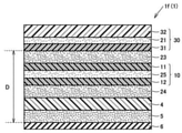
도 1은 본 발명의 광학 적층체의 일례를 모식적으로 도시하는 개략 단면도이다.
도 2는 본 발명의 광학 적층체의 다른 일례를 모식적으로 도시하는 개략 단면도이다.
도 3은 본 발명의 광학 적층체의 또 다른 일례를 모식적으로 도시하는 개략 단면도이다.
도 4는 본 발명의 광학 적층체의 또 다른 일례를 모식적으로 도시하는 개략 단면도이다.
도 5는 본 발명의 광학 적층체의 또 다른 일례를 모식적으로 도시하는 개략 단면도이다.
도 6은 본 발명의 광학 적층체의 또 다른 일례를 모식적으로 도시하는 개략 단면도이다. BRIEF DESCRIPTION OF THE DRAWINGS It is a schematic sectional drawing which shows typically an example of the optical laminated body of this invention.
It is a schematic sectional drawing which shows typically another example of the optical laminated body of this invention.
It is a schematic sectional drawing which shows typically still another example of the optical laminated body of this invention.
It is a schematic sectional drawing which shows typically still another example of the optical laminated body of this invention.
It is a schematic sectional drawing which shows typically still another example of the optical laminated body of this invention.
It is a schematic sectional drawing which shows typically still another example of the optical laminated body of this invention.
이하, 도면을 참조하여 본 발명의 광학 적층체 및 박리 방법의 바람직한 실시형태에 관해 설명한다. 이하의 모든 도면은, 본 발명의 이해를 돕기 위해 도시하는 것이며, 도면에 도시되는 각 구성요소의 사이즈나 형상은, 실제 구성 요소의 사이즈나 형상과 반드시 일치하지는 않는다. EMBODIMENT OF THE INVENTION Hereinafter, with reference to drawings, preferable embodiment of the optical laminated body and peeling method of this invention is described. All the drawings below are shown to help the understanding of the present invention, and the size or shape of each component shown in the drawing does not necessarily match the size or shape of the actual component.
(광학 적층체)(optical laminate)
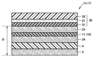
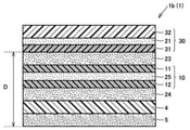
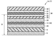
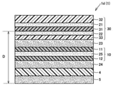
도 1∼도 6은, 본 실시형태의 광학 적층체의 일례를 모식적으로 도시하는 개략 단면도이다. 본 실시형태의 광학 적층체(1a∼1f)(이하, 이들을 통합하여 「광학 적층체(1)」라고 하는 경우가 있다.)는, 직선 편광층(31), 위상차층(10), 배리어층(4) 및 점착제층(5)을 이 순으로 구비한다. 직선 편광층(31)은, 요오드가 흡착 배향되어 있는 폴리비닐알콜계 수지 필름(이하, 「PVA계 필름」이라고 하는 경우가 있다.)이다. 위상차층(10)은, 중합성 액정 화합물이 중합 경화한 경화물층(후술하는 제1 경화물층(11), 제2 경화물층(12) 등)을 적어도 1층 포함한다. 배리어층(4)은 점착제층(5)에 직접 접하여 형성되어 있다. 배리어층(4)의 온도 40℃, 상대 습도 90% RH에서의 투습도는 1 g/㎡/24 hr 이상 2000 g/㎡/24 hr 이하이다. 광학 적층체(1)는, 직선 편광층(31)의 위상차층(10)측의 표면으로부터, 점착제층(5)의 배리어층(4)측과는 반대측의 표면까지의 거리 D가 55 μm 이하이다. 1-6 is a schematic sectional drawing which shows typically an example of the optical laminated body of this embodiment. The
광학 적층체(1)는, 도 5 및 도 6에 도시하는 광학 적층체(1e, 1f)와 같이, 점착제층(5)의 배리어층(4)측과는 반대측에 금속층(6)을 더 포함하고 있어도 좋다. 금속층(6)은, 점착제층(5)에 직접 접하여 형성되어 있는 것이 바람직하다. The
상기 층구조를 갖는 광학 적층체(1)에서는, 점착제층(5)을 통해 광학 적층체(1a∼1d)를 금속층(6)에 적층한 경우나, 광학 적층체(1e, 1f)에 있어서, 금속층(6)에 발생하는 부식, 특히 금속층(6)에 발생하는 공식(孔食)을 억제할 수 있다. 광학 적층체(1)에 의해 금속층(6)의 부식을 억제할 수 있는 이유는 다음과 같이 추측된다. 직선 편광층으로서 요오드가 흡착 배향되어 있는 PVA계 필름은, 고온 고습 환경하에서 PVA계 필름으로부터 미량의 요오드가 배어 나오는 경우가 있다. 직선 편광층 및 금속층을 포함하는 적층체에서는, 직선 편광층으로부터 배어 나온 요오드가 금속층에 도달하면, 금속층을 부식시킨다고 생각된다. 따라서, 광학 적층체(1)에서는, 금속층(6)에 접합하기 위한 점착제층(5)에 접하도록, 투습도가 상기 범위에 있는 배리어층(4)을 형성하고 있다. 이것에 의해, 거리 D가 55 μm 이하라는 박형의 광학 적층체(1)라 하더라도, 직선 편광층(31)으로부터 배어 나온 요오드가 금속층(6)에 도달하는 것을 억제할 수 있고, 금속층(6)의 부식을 억제할 수 있다고 생각된다. In the
광학 적층체(1)는, 도 1∼도 6에 도시하는 바와 같이, 직선 편광층(31)의 한면 또는 양면에 보호층(32, 33)(이하, 각각을 「제1 보호층(32)」 및 「제2 보호층(33)」이라고 하는 경우가 있다.)을 갖는 편광판(30)을 포함하고 있어도 좋다. 광학 적층체(1)의 박형화의 관점에서는, 편광판(30)은, 직선 편광층(31)의 한면에만 제1 보호층(32) 또는 제2 보호층(33)을 갖는 것이 바람직하다. 직선 편광층(31)의 한면에만 보호층을 갖는 경우, 직선 편광층(31)의 보호의 관점에서, 도 1 및 도 2에 도시하는 바와 같이 직선 편광층(31)의 위상차층(10)측과는 반대측의 제1 보호층(32)을 갖는 것이 바람직하다. 광학 적층체(1)는 배리어층(4)을 갖고 있기 때문에, 제1 보호층(32)이 형성되고 제2 보호층(33)이 형성되지 않은 경우라도 금속층(6)의 부식을 효과적으로 억제할 수 있다. 제1 보호층(32) 및/또는 제2 보호층(33)은, 예컨대 도 1∼도 6에 도시하는 바와 같이, 제1 접합층(21) 및/또는 제2 접합층(22)을 통해 직선 편광층(31) 상에 형성해도 좋다. 제1 접합층(21) 및 제2 접합층(22)은 접착제층 또는 점착제층이다. As shown in FIGS. 1-6, the optical laminated
광학 적층체(1)는, 직선 편광층(31) 또는 편광판(30)과 위상차층(10)을 접합하기 위한 접합층(Y)(23)을 더 포함하고 있어도 좋다. 이 경우, 위상차층(10)은, 예컨대 도 1∼도 6에 도시하는 바와 같이, 접합층(Y)(23)을 통해 직선 편광층(31) 또는 편광판(30) 상에 형성된다. 접합층(Y)(23)은 접착제층 또는 점착제층이다. 혹은, 위상차층(10)은, 직선 편광층(31) 또는 편광판(30)에 직접 접하도록 형성해도 좋다. The
광학 적층체(1)는, 위상차층(10)과 배리어층(4)을 접합하기 위한 접합층(Z)(24)을 더 포함하고 있어도 좋다. 이 경우, 배리어층(4)은, 예컨대 도 1∼도 6에 도시하는 바와 같이, 접합층(Z)(24)을 통해 위상차층(10) 상에 형성된다. 접합층(Z)(24)은 접착제층 또는 점착제층이다. 혹은, 배리어층(4)은 위상차층(10)에 직접 접하도록 형성해도 좋다. 광학 적층체(1)가 접합층(Z)(24)을 포함하는 경우, 접합층(Z)(24)은 접착제층인 것이 바람직하다. 이것에 의해, 예컨대 광학 적층체(1)를 절단날에 의해 재단한 경우에, 재단면에서 위상차층(10)이 변형되는 것을 억제할 수 있다. The
광학 적층체(1)에 있어서, 상기 거리 D는 55 μm 이하이며, 48 μm 이하이어도 좋고, 45 μm 이하이어도 좋고, 40 μm 이하이어도 좋고, 35 μm 이하이어도 좋고, 30 μm 이하이어도 좋고, 25 μm 이하이어도 좋다. 거리 D는, 통상 10 μm 이상이며, 15 μm 이상이어도 좋고, 20 μm 이상이어도 좋다. In the
광학 적층체(1)를 온도 85℃, 상대 습도 85% RH의 조건하에 240시간 보관한 후의 상기 점착제층에서의 요오드량은 250 ppm 이하인 것이 바람직하고, 200 ppm 이하인 것이 보다 바람직하고, 150 ppm 이하인 것이 더욱 바람직하고, 100 ppm 이하인 것이 보다 더 바람직하고, 50 ppm 이하이어도 좋고, 30 ppm 이하이어도 좋고, 10 ppm 이하이어도 좋다. 상기 요오드량이 상기 범위 내인 것에 의해, 광학 적층체(1)를 고온 고습 환경하에 노출시킨 경우의 금속층(6)의 부식이 억제되기 쉽다. 상기 요오드량은, 예컨대 배리어층(4)의 상기 투습도를 조정, 직선 편광층(31)에 제1 보호층(32) 및/또는 제2 보호층(33)을 형성, 제1 보호층(32) 및/또는 제2 보호층(33)의 종류나 두께를 조정하는 등에 의해 조정할 수 있다. 상기 요오드량은, 후술하는 실시예에 기재된 방법에 의해 측정할 수 있다. The amount of iodine in the pressure-sensitive adhesive layer after storing the
도 1∼도 4에 도시하는 광학 적층체(1a∼1d)는, 점착제층(5)의 위상차층(10)측과는 반대측에 박리 필름을 갖고 있어도 좋다. 박리 필름은, 점착제층(5)을 피복 보호하거나 또는, 점착제층(5)을 지지하는 것이며, 점착제층(5)에 대하여 박리 가능한 세퍼레이터로서의 기능을 갖는다. 박리 필름으로는, 기재 필름의 점착제층측의 표면에 실리콘 처리 등의 이형 처리된 필름을 들 수 있다. 기재 필름을 이루는 수지 재료로는, 후술하는 보호층을 이루는 수지 재료를 들 수 있다. 수지 필름은 1층 구조이어도 좋고, 2층 이상의 다층 구조의 다층 수지 필름이어도 좋다. The optical
도 1∼도 4에 도시하는 광학 적층체(1a∼1d)는, 원편광판을 구성할 수 있고, 유기 EL(일렉트로 루미너센스) 표시 장치 등에서의 반사 방지 필름으로서 이용할 수 있다. 광학 적층체(1a∼1d)가 원편광판인 경우, 위상차층(10)에 포함되는 경화물층의 적어도 1층은, λ/4 파장 위상차 특성을 갖는 층인 것이 바람직하다. 도 2, 도 4 및 도 6에 도시하는 바와 같이, 위상차층(10)이 제1 경화물층(11) 및 제2 경화물층(12)을 포함하는 경우, 제1 경화물층(11) 및 제2 경화물층(12)은 각각, [i] 1/2 파장 위상차층 및 1/4 파장 위상차층, [ii] 1/4 파장 위상차층 및 포지티브 C 플레이트, 또는, [iii] 포지티브 C 플레이트 및 1/4 파장 위상차층이어도 좋다. λ/4 파장 위상차층은 역파장 분산성을 갖는 것이어도 좋다. The
광학 적층체(1)는, 스마트폰이나 태블릿 등의 표시 장치에 이용할 수 있고, 특히 터치 패널 방식의 표시 장치에 적합하게 이용할 수 있다. 표시 장치로는, 유기 EL 표시 장치, 액정 표시 장치 등을 들 수 있다. 표시 장치는 플렉시블 디스플레이이어도 좋다. The
이하, 광학 적층체(1)에서 이용한 각 부재의 상세에 관해 설명한다. Hereinafter, the detail of each member used by the optical
(직선 편광층)(linear polarization layer)
직선 편광층은, 무편광의 광을 입사시켰을 때, 흡수축에 직교하는 진동면을 갖는 직선 편광을 투과시키는 성질을 갖는다. 직선 편광층은, 요오드가 흡착 배향되어 있는 PVA계 필름이다. The linearly polarized light layer has a property of transmitting linearly polarized light having an oscillation plane orthogonal to the absorption axis when unpolarized light is incident thereon. The linearly polarizing layer is a PVA-based film in which iodine is oriented by adsorption.
직선 편광층은, 예컨대, 폴리비닐알콜 필름, 부분 포르말화 폴리비닐알콜 필름, 에틸렌·아세트산비닐 공중합체계 부분 비누화 필름 등의 PVA계 필름에, 요오드에 의한 염색 처리 및 연신 처리된 것 등을 들 수 있다. 필요에 따라서, 염색 처리에 의해 요오드가 흡착 배향된 PVA계 필름을 붕산 수용액으로 처리하고, 그 후에, 붕산 수용액을 씻어내는 세정 공정을 행해도 좋다. 각 공정에는 공지의 방법을 채용할 수 있다. The linear polarizing layer includes, for example, a polyvinyl alcohol film, a partially formalized polyvinyl alcohol film, and a PVA-based film such as an ethylene/vinyl acetate copolymer-based partially saponified film, dyed with iodine and stretched. there is. If necessary, the PVA-based film in which the iodine is adsorbed or oriented by the dyeing treatment may be treated with an aqueous boric acid solution, and then a washing step of rinsing the boric acid aqueous solution may be performed. A well-known method can be employ|adopted for each process.
폴리비닐알콜계 수지(이하, 「PVA계 수지」라고 하는 경우가 있다.)는, 폴리아세트산비닐계 수지를 비누화하는 것에 의해 제조할 수 있다. 폴리아세트산비닐계 수지는, 아세트산비닐의 단독 중합체인 폴리아세트산비닐 외에, 아세트산비닐과 아세트산비닐에 공중합 가능한 다른 단량체와의 공중합체일 수도 있다. 아세트산비닐에 공중합 가능한 다른 단량체로는, 예컨대, 불포화 카르복실산류, 올레핀류, 비닐에테르류, 불포화 술폰산류, 암모늄기를 갖는 아크릴아미드류 등을 들 수 있다. The polyvinyl alcohol-based resin (hereinafter, sometimes referred to as “PVA-based resin”) can be produced by saponifying polyvinyl acetate-based resin. Polyvinyl acetate-type resin may be a copolymer of vinyl acetate and other monomer copolymerizable with vinyl acetate other than polyvinyl acetate which is a homopolymer of vinyl acetate. Examples of the other monomer copolymerizable with vinyl acetate include unsaturated carboxylic acids, olefins, vinyl ethers, unsaturated sulfonic acids, and acrylamides having an ammonium group.
PVA계 수지의 비누화도는, 통상 85∼100 몰% 정도이며, 바람직하게는 98 몰% 이상이다. PVA계 수지는 변성되어 있어도 좋고, 예컨대, 알데히드류로 변성된 폴리비닐포르말이나 폴리비닐아세탈 등도 사용 가능하다. PVA계 수지의 평균 중합도는, 통상 1,000∼10,000 정도이며, 바람직하게는 1,500∼5,000 정도이다. PVA계 수지의 평균 중합도는, JIS K 6726(1994)에 준거하여 구할 수 있다. 평균 중합도가 1000 미만이면 바람직한 편광 성능을 얻기 어렵고, 10000 초과이면 필름 가공성이 떨어지는 경우가 있다. The saponification degree of PVA-type resin is about 85-100 mol% normally, Preferably it is 98 mol% or more. The PVA-based resin may be modified, for example, polyvinyl formal or polyvinyl acetal modified with aldehydes may be used. The average degree of polymerization of PVA-type resin is about 1,000-10,000 normally, Preferably it is about 1,500-5,000. The average degree of polymerization of PVA-type resin can be calculated|required based on JISK6726 (1994). If the average degree of polymerization is less than 1000, it is difficult to obtain desirable polarization performance, and if it exceeds 10000, the film workability may be poor.
PVA계 필름을 포함하는 직선 편광층의 제조 방법은, 기재 필름을 준비하고, 기재 필름 상에 PVA계 수지 등의 수지의 용액을 도포하고, 용매를 제거하는 건조 등을 행하여 기재 필름 상에 수지층을 형성하는 공정을 포함하는 것이어도 좋다. 또, 기재 필름의 수지층이 형성되는 면에는, 미리 프라이머층을 형성할 수 있다. 기재 필름으로는, PET 등의 수지 필름이나, 후술하는 보호층에 이용할 수 있는 열가소성 수지를 이용한 필름을 사용할 수 있다. 프라이머층의 재료로는, 직선 편광층에 이용되는 친수성 수지를 가교한 수지 등을 들 수 있다. The manufacturing method of the linear polarizing layer containing a PVA-type film prepares a base film, apply|coats a solution of resin, such as a PVA-type resin, on a base film, and performs drying etc. which remove a solvent, and a resin layer on a base film. It may include a step of forming Moreover, a primer layer can be previously formed in the surface in which the resin layer of a base film is formed. As a base film, resin films, such as PET, and the film using the thermoplastic resin which can be used for the protective layer mentioned later can be used. As a material of a primer layer, resin etc. which bridge|crosslinked the hydrophilic resin used for a linearly polarizing layer are mentioned.
이어서, 필요에 따라서 수지층의 수분 등의 용매량을 조정하고, 그 후, 기재 필름 및 수지층을 일축 연신하고, 계속해서, 수지층을 요오드로 염색하여 요오드를 수지층에 흡착 배향시킨다. 다음으로, 필요에 따라서 요오드가 흡착 배향된 수지층을 붕산 수용액으로 처리하고, 그 후에, 붕산 수용액을 씻어내는 세정 공정을 행한다. 이것에 의해, 요오드가 흡착 배향된 수지층, 즉, 직선 편광층의 필름이 제조된다. 각 공정에는 공지의 방법을 채용할 수 있다. Next, the amount of solvents, such as water|moisture content, of a resin layer is adjusted as needed, a base film and a resin layer are uniaxially stretched after that, Then, the resin layer is dyed with iodine, and an iodine is adsorbed and orientated to a resin layer. Next, if necessary, the resin layer in which the iodine is adsorbed orientated is treated with an aqueous boric acid solution, and then a washing step of rinsing the boric acid aqueous solution is performed. Thereby, the film of the resin layer by which the iodine adsorption|suction orientation was carried out, ie, a linear polarizing layer, is manufactured. A well-known method can be employ|adopted for each process.
요오드가 흡착 배향된 PVA계 필름 또는 수지층을 처리하는 붕산 함유 수용액에서의 붕산의 양은, 통상, 물 100 중량부당 2∼15 중량부 정도이며, 5∼12 중량부가 바람직하다. 2색성 색소로서 요오드를 이용하는 경우에는, 이 붕산 함유 수용액은 요오드화칼륨을 함유하는 것이 바람직하다. 붕산 함유 수용액에서의 요오드화칼륨의 양은, 통상, 물 100 중량부당 0.1∼15 중량부 정도이며, 5∼12 중량부 정도가 바람직하다. 붕산 함유 수용액에 대한 침지 시간은, 통상 60∼1,200초 정도이며, 150∼600초 정도가 바람직하고, 200∼400초 정도가 보다 바람직하다. 붕산 함유 수용액의 온도는 통상 50℃ 이상이며, 50∼85℃가 바람직하고, 60∼80℃가 보다 바람직하다. The amount of boric acid in the boric acid-containing aqueous solution for treating the PVA-based film or resin layer in which iodine is adsorbed and oriented is usually about 2 to 15 parts by weight, preferably 5 to 12 parts by weight, per 100 parts by weight of water. When using an iodine as a dichroic dye, it is preferable that this boric-acid containing aqueous solution contains potassium iodide. The quantity of potassium iodide in boric-acid containing aqueous solution is about 0.1-15 weight part per 100 weight part of water normally, and about 5-12 weight part is preferable. The immersion time with respect to boric-acid containing aqueous solution is about 60 to 1,200 second normally, about 150 to 600 second is preferable, and its about 200 to 400 second is more preferable. The temperature of boric acid containing aqueous solution is 50 degreeC or more normally, 50-85 degreeC is preferable and 60-80 degreeC is more preferable.
PVA계 필름, 및, 기재 필름 및 수지층의 일축 연신은, 염색전에 행해도 좋고, 염색중에 행해도 좋고, 염색후의 붕산 처리중에 행해도 좋고, 이들 복수의 단계에서 각각 일축 연신을 행해도 좋다. PVA계 필름, 및, 기재 필름 및 수지층은, MD 방향(필름 반송 방향)으로 일축 연신해도 좋고, 이 경우, 주속이 상이한 롤 사이에서 일축 연신해도 좋고, 열 롤을 이용하여 일축 연신해도 좋다. 또한, PVA계 필름, 및, 기재 필름 및 수지층은, TD 방향(필름 반송 방향에 수직인 방향)으로 일축 연신해도 좋고, 이 경우, 소위 텐터법을 사용할 수 있다. 또한, 상기 연신은, 대기중에서 연신을 행하는 건식 연신이어도 좋고, 용제로 PVA계 필름 또는 수지층을 팽윤시킨 상태로 연신을 행하는 습식 연신이어도 좋다. 직선 편광층의 성능을 발현하기 위해서는 연신 배율은 4배 이상이며, 5배 이상인 것이 바람직하고, 특히 5.5배 이상이 바람직하다. 연신 배율의 상한은 특별히 없지만, 파단 등을 억제하는 관점에서 8배 이하가 바람직하다. The uniaxial stretching of the PVA-based film and the base film and the resin layer may be performed before dyeing, during dyeing, during boric acid treatment after dyeing, or may be uniaxially stretched in each of these plural steps. The PVA-based film and the base film and the resin layer may be uniaxially stretched in the MD direction (film conveyance direction), and in this case, may be uniaxially stretched between rolls having different peripheral speeds, or may be uniaxially stretched using a hot roll. In addition, you may uniaxially stretch a PVA-type film, and a base film, and a resin layer in TD direction (direction perpendicular|vertical to a film conveyance direction), In this case, a so-called tenter method can be used. Further, the stretching may be dry stretching in which stretching is performed in the air, or wet stretching in which the PVA-based film or resin layer is swollen with a solvent. In order to express the performance of a linearly polarizing layer, a draw ratio is 4 times or more, It is preferable that it is 5 times or more, and 5.5 times or more are especially preferable. Although there is no upper limit in particular of a draw ratio, 8 times or less is preferable from a viewpoint of suppressing a fracture|rupture etc.
기재 필름을 이용하는 제조 방법으로 제작한 직선 편광층은, 후술하는 보호층을 적층한 후에 기재 필름을 박리함으로써 얻을 수 있다. 이 방법에 의하면, 직선 편광층을 한층 더 박막화하는 것이 가능해진다. The linearly polarizing layer produced by the manufacturing method using a base film can be obtained by peeling a base film, after laminating|stacking the protective layer mentioned later. According to this method, it becomes possible to further thin the linearly polarizing layer.
직선 편광층의 두께는, 1 μm 이상인 것이 바람직하고, 2 μm 이상이어도 좋고, 5 μm 이상이어도 좋고, 또한, 30 μm 이하인 것이 바람직하고, 15 μm 이하인 것이 보다 바람직하고, 10 μm 이하인 것이 더욱 바람직하고, 8 μm 이하이어도 좋다. 직선 편광층의 두께가 작을수록 고온 고습 환경하에서의 요오드가 배어나오기 쉽다. 그 때문에, 직선 편광층의 두께가 작은 경우, 본 실시형태의 광학 적층체(1)과 같이 하는 것에 의해, 금속층(6)에 발생하는 부식을 효과적으로 억제할 수 있다. The thickness of the linearly polarizing layer is preferably 1 µm or more, may be 2 µm or more, may be 5 µm or more, and is preferably 30 µm or less, more preferably 15 µm or less, still more preferably 10 µm or less, , may be 8 µm or less. The smaller the thickness of the linear polarization layer, the easier it is for iodine to permeate in a high-temperature, high-humidity environment. Therefore, when the thickness of a linearly polarizing layer is small, by setting it as the optical
요오드가 흡착 배향된 PVA계 필름 또는 수지층을 붕산 수용액으로 처리하고, 그 후에 붕산 수용액을 씻어내는 세정 공정에서, 붕산 수용액 중의 붕산 농도가 낮을수록, 고온 고습 환경하에서의 요오드가 배어나오기 쉽다. 그 때문에, 직선 편광층의 제조 공정에서 이용한 상기 붕산 수용액 중의 붕산 농도가 낮은 경우, 본 실시형태의 광학 적층체(1)와 같이 하는 것에 의해, 금속층(6)에 발생하는 부식을 효과적으로 억제할 수 있다. In the washing process of treating the PVA-based film or resin layer in which iodine is adsorbed and oriented with an aqueous boric acid solution and then washing off the aqueous boric acid solution, the lower the boric acid concentration in the boric acid aqueous solution, the easier it is to seep out iodine in a high-temperature, high-humidity environment. Therefore, when the concentration of boric acid in the aqueous boric acid solution used in the production process of the linearly polarized light layer is low, the corrosion generated in the
(편광판)(Polarizer)
직선 편광층(31)은, 도 1∼도 6에 도시하는 바와 같이, 그 한면 또는 양면에 보호층(제1 보호층(32) 및/또는 제2 보호층(33))을 적층하여 편광판(30)으로 할 수 있다. 이 편광판(30)은 소위 직선 편광판이다. 직선 편광층(31)의 한면 또는 양면에 적층할 수 있는 제1 보호층(32) 및/또는 제2 보호층(33)으로는, 예컨대, 투명성, 기계적 강도, 열안정성, 수분 차단성, 등방성, 연신성 등이 우수한 열가소성 수지로 형성된 필름이 이용된다. 열가소성 수지의 구체예로는, 트리아세틸셀룰로오스 등의 셀룰로오스 수지; 폴리에틸렌테레프탈레이트, 폴리에틸렌나프탈레이트 등의 폴리에스테르 수지; 폴리에테르술폰 수지; 폴리술폰 수지; 폴리카보네이트 수지; 나일론이나 방향족 폴리아미드 등의 폴리아미드 수지; 폴리이미드 수지; 폴리에틸렌, 폴리프로필렌, 에틸렌·프로필렌 공중합체 등의 폴리올레핀 수지; 시클로계 및 노르보넨 구조를 갖는 고리형 폴리올레핀 수지(노르보넨계 수지라고도 함); (메트)아크릴 수지; 폴리아릴레이트 수지; 폴리스티렌 수지; 폴리비닐알콜 수지, 및 이들의 혼합물을 들 수 있다. 제1 보호층(32) 및 제2 보호층(33)의 수지 조성은 동일해도 좋고 상이해도 좋다. 또, 본 명세서에서 「(메트)아크릴」이란, 아크릴 또는 메타크릴의 어느 것이어도 좋은 것을 의미한다. (메트)아크릴레이트 등의 「(메트)」도 동일한 의미이다. As shown in Figs. 1 to 6, the linearly polarizing
제1 보호층(32) 및 제2 보호층(33)의 온도 40℃, 상대 습도 90% RH에서의 투습도는 특별히 한정되지 않는다. 본 실시형태의 광학 적층체(1)에서는, 제1 보호층(32)의 상기 투습도가 300 g/㎡/24 hr 이하인 경우에 효과적으로, 또한, 제1 보호층(32)의 상기 투습도가 100 g/㎡/24 hr 이하인 경우에 의해 한층 더 효과적으로, 금속층의 부식을 억제할 수 있다. 제1 보호층(32)의 상기 투습도가 작아지면, 광학 적층체(1)에 있어서 직선 편광층(31) 중의 요오드가 제1 보호층(32)측으로 이동하기 어려워지고, 점착제층(5)측으로 이동하기 쉬워진다. 광학 적층체(1)에서는 배리어층(4)을 갖기 때문에, 상기와 같이 점착제층(5)측으로 요오드가 이동하기 쉬워지더라도, 점착제층(5)의 배리어층(4)측과는 반대측에 형성된 금속층(6)이 부식되는 것을 억제할 수 있다. 제1 보호층(32) 및 제2 보호층(33)의 상기 투습도는, 투습도 시험법(컵법, JIS Z 0208)에 의해 측정할 수 있다. The moisture permeability of the first
제1 보호층(32) 및 제2 보호층(33)은, 위상차 특성을 갖는 것이어도 좋고, 하드코트층이나 반사 방지층 등의 기능 특성을 갖는 광학 기능층이어도 좋다. 제1 보호층(32) 및 제2 보호층(33)의 두께는 각각 독립적으로, 3 μm 이상인 것이 바람직하고, 5 μm 이상인 것이 보다 바람직하고, 또한, 50 μm 이하인 것이 바람직하고, 30 μm 이하인 것이 보다 바람직하다. The first
제1 보호층(32) 및 제2 보호층(33)과 직선 편광층은, 각각 제1 접합층(21) 및 제2 접합층(22)에 의해 접합되어 있는 것이 바람직하다(도 1∼도 6). 제1 접합층(21) 및 제2 접합층(22)은 접착제층 또는 점착제층이다. 접착제층 및 점착제층으로는, 후술하는 것을 이용할 수 있다. 제1 접합층(21) 및 제2 접합층(22)으로는, 후술하는 수계 접착제를 이용하여 형성된 접착제층인 것이 바람직하다. It is preferable that the 1st
(위상차층)(retardation layer)
위상차층(10)은 위상차 특성을 갖는 층을 포함한다. 위상차 특성을 갖는 층으로는, 중합성 액정 화합물이 중합 경화한 경화물층을 들 수 있다. 위상차층(10)은, 적어도 1층의 경화물층을 포함하고, 2층 이상의 경화물층을 포함하고 있어도 좋다. 2층 이상의 경화물층을 포함하는 경우, 위상차층(10)은, 경화물층을 서로 접합하기 위한 접합층(예컨대, 도 2, 도 4 및 도 6에 도시하는 접합층(X)(25))을 포함하고 있어도 좋다. 경화물층은, 1/2 파장 위상차층, 1/4 파장 위상차층 또는 포지티브 C 플레이트일 수 있다. 1/4 파장 위상차층은 역파장 분산성이어도 좋다. 위상차층이 2 이상의 경화물층을 포함하는 경우, 경화물층은 서로 동일한 위상차 특성을 갖고 있어도 좋고, 서로 다른 위상차 특성을 갖고 있어도 좋다. The
중합성 액정 화합물로는, 막대형의 중합성 액정 화합물 및 원반형의 중합성 액정 화합물을 들 수 있고, 이들 중의 한쪽을 이용해도 좋고, 이들 양쪽을 포함하는 혼합물을 이용해도 좋다. 막대형의 중합성 액정 화합물이 기재층에 대하여 수평 배향 또는 수직 배향된 경우는, 상기 중합성 액정 화합물의 광축은 상기 중합성 액정 화합물의 장축 방향과 일치한다. 원반형의 중합성 액정 화합물이 배향된 경우는, 상기 중합성 액정 화합물의 광축은, 상기 중합성 액정 화합물의 원반면에 대하여 직교하는 방향으로 존재한다. 막대형의 중합성 액정 화합물로는, 예컨대, 일본 특허 공표 11-513019호 공보(청구항 1 등)에 기재된 것을 적합하게 이용할 수 있다. 원반형의 중합성 액정 화합물로는, 일본 특허 공개 제2007-108732호 공보(단락 [0020]∼[0067] 등), 일본 특허 공개 제2010-244038호 공보(단락 [0013]∼[0108] 등)에 기재된 것을 적합하게 이용할 수 있다. Examples of the polymerizable liquid crystal compound include a rod-shaped polymerizable liquid crystal compound and a disk-shaped polymerizable liquid crystal compound, and either one of these may be used, or a mixture containing both of them may be used. When the rod-shaped polymerizable liquid crystal compound is horizontally aligned or vertically aligned with respect to the base layer, the optical axis of the polymerizable liquid crystal compound coincides with the long axis direction of the polymerizable liquid crystal compound. When the disk-shaped polymerizable liquid crystal compound is oriented, the optical axis of the polymerizable liquid crystal compound exists in a direction orthogonal to the disk surface of the polymerizable liquid crystal compound. As the rod-shaped polymerizable liquid crystal compound, for example, those described in Japanese Patent Application Laid-Open No. 11-513019 (
중합성 액정 화합물을 중합함으로써 형성되는 경화물층이 면내 위상차를 발현하기 위해서는, 중합성 액정 화합물을 적합한 방향으로 배향시키면 된다. 중합성 액정 화합물이 막대형인 경우는, 상기 중합성 액정 화합물의 광축을 기재층 평면에 대하여 수평으로 배향시킴으로써 면내 위상차가 발현하고, 이 경우, 광축 방향과 지상축 방향은 일치한다. 중합성 액정 화합물이 원반형인 경우는, 상기 중합성 액정 화합물의 광축을 기재층 평면에 대하여 수평으로 배향시킴으로써 면내 위상차가 발현하고, 이 경우, 광축과 지상축은 직교한다. 중합성 액정 화합물의 배향 상태는, 배향층과 중합성 액정 화합물의 조합에 의해 조정할 수 있다. In order for the hardened|cured material layer formed by superposing|polymerizing a polymeric liquid crystal compound to express in-plane retardation, what is necessary is just to orientate a polymeric liquid crystal compound in a suitable direction. When the polymerizable liquid crystal compound is rod-shaped, the in-plane retardation is expressed by aligning the optical axis of the polymerizable liquid crystal compound horizontally with respect to the plane of the substrate layer, and in this case, the optical axis direction and the slow axis direction coincide. When the polymerizable liquid crystal compound is discoid, the in-plane retardation is expressed by aligning the optical axis of the polymerizable liquid crystal compound horizontally with respect to the plane of the base layer, and in this case, the optical axis and the slow axis are orthogonal to each other. The orientation state of a polymeric liquid crystal compound can be adjusted by the combination of an orientation layer and a polymeric liquid crystal compound.
중합성 액정 화합물은, 적어도 하나의 중합성기를 가지며 액정성을 갖는 화합물이다. 중합성 액정 화합물을 2종류 이상을 병용하는 경우, 적어도 1종류가 분자 내에 2 이상의 중합성기를 갖는 것이 바람직하다. 중합성기란, 중합 반응에 관여하는 기를 의미하며, 광중합성기인 것이 바람직하다. 여기서, 광중합성기란, 후술하는 광중합 개시제로부터 발생한 활성 라디칼이나 산 등에 의해 중합 반응에 관여할 수 있는 기를 말한다. 중합성기로는, 비닐기, 비닐옥시기, 1-클로로비닐기, 이소프로페닐기, 4-비닐페닐기, 아크릴로일옥시기, 메타크릴로일옥시기, 옥시라닐기, 옥세타닐기, 스티릴기, 알릴기 등을 들 수 있다. 그 중에서도, 아크릴로일옥시기, 메타크릴로일옥시기, 비닐옥시기, 옥시라닐기 및 옥세타닐기가 바람직하고, 아크릴로일옥시기가 보다 바람직하다. 중합성 액정 화합물이 갖는 액정성은 서모트로픽성 액정이어도 좋고 리오트로픽 액정이어도 좋으며, 서모트로픽 액정을 질서도로 분류하면, 네마틱 액정이어도 좋고 스멕틱 액정이어도 좋다. A polymerizable liquid crystal compound is a compound which has at least 1 polymerizable group and has liquid crystallinity. When using two or more types of polymerizable liquid crystal compounds together, it is preferable that at least 1 type has two or more polymeric groups in a molecule|numerator. A polymerizable group means group which participates in a polymerization reaction, and it is preferable that it is a photopolymerizable group. Here, the photopolymerizable group refers to a group capable of participating in a polymerization reaction by an active radical or an acid generated from a photopolymerization initiator described later. Examples of the polymerizable group include vinyl group, vinyloxy group, 1-chlorovinyl group, isopropenyl group, 4-vinylphenyl group, acryloyloxy group, methacryloyloxy group, oxiranyl group, oxetanyl group, styryl group, allyl group and the like. Among them, an acryloyloxy group, a methacryloyloxy group, a vinyloxy group, an oxiranyl group, and an oxetanyl group are preferable, and an acryloyloxy group is more preferable. The liquid crystal property of the polymerizable liquid crystal compound may be either a thermotropic liquid crystal or a lyotropic liquid crystal. If the thermotropic liquid crystal is classified by order, it may be either a nematic liquid crystal or a smectic liquid crystal.
위상차층(10)이 중합성 액정 화합물의 경화물층을 포함하는 경우, 위상차층(10)은 배향층을 포함하고 있어도 좋다. 배향층은, 중합성 액정 화합물을 원하는 방향으로 배향시키는 배향 규제력을 갖는다. 배향층은, 중합성 액정 화합물의 분자축을 기재층에 대하여 수직 배향시킨 수직 배향층이어도 좋고, 중합성 액정 화합물의 분자축을 기재층에 대하여 수평 배향시킨 수평 배향층이어도 좋고, 중합성 액정 화합물의 분자축을 기재층에 대하여 경사 배향시키는 경사 배향층이어도 좋다. 위상차층이 2 이상의 배향층을 포함하는 경우, 배향층은 서로 동일해도 좋고 서로 달라도 좋다.When the
배향층으로는, 중합성 액정 화합물을 포함하는 액정층 형성용 조성물의 도공 등에 의해 용해되지 않는 용매 내성을 가지며, 용매의 제거나 중합성 액정 화합물의 배향을 위한 가열 처리에 대한 내열성을 갖는 것이 바람직하다. 배향층으로는, 배향성 폴리머로 형성된 배향성 폴리머층, 광배향 폴리머로 형성된 광배향성 폴리머층, 층표면에 요철 패턴이나 복수의 그루브(홈)를 갖는 그루브 배향층을 들 수 있다. The alignment layer preferably has solvent resistance that does not dissolve by coating of a composition for forming a liquid crystal layer containing a polymerizable liquid crystal compound, etc., and has heat resistance to heat treatment for removal of the solvent or alignment of the polymerizable liquid crystal compound. Do. Examples of the alignment layer include an alignment polymer layer formed of an alignment polymer, a photo alignment polymer layer formed of a photo alignment polymer, and a groove alignment layer having an uneven pattern or a plurality of grooves on the surface of the layer.
경화물층의 두께는, 0.1 μm 이상이어도 좋고, 0.5 μm 이상이어도 좋고, 1 μm 이상이어도 좋고, 2 μm 이상이어도 좋고, 또한, 10 μm 이하인 것이 바람직하고, 8 μm 이하이어도 좋고, 5 μm 이하이어도 좋다. The thickness of the cured product layer may be 0.1 µm or more, 0.5 µm or more, 1 µm or more, 2 µm or more, and preferably 10 µm or less, 8 µm or less, or 5 µm or less good night.
중합성 액정 화합물의 경화물층은, 기재층 상에, 중합성 액정 화합물을 포함하는 액정층 형성용 조성물을 도포, 건조하고, 중합성 액정 화합물을 중합시키는 것에 의해 형성할 수 있다. 액정층 형성용 조성물은, 기재층 상에 형성된 배향층 상에 도포해도 좋다. The hardened|cured material layer of a polymeric liquid crystal compound can be formed by apply|coating and drying the composition for liquid crystal layer formation containing a polymerizable liquid crystal compound on a base material layer, and polymerizing a polymeric liquid crystal compound. You may apply|coat the composition for liquid crystal layer formation on the orientation layer formed on the base material layer.
기재층으로는, 수지 재료로 형성된 필름을 이용할 수 있고, 예컨대 상기 보호층을 형성하기 위해 이용하는 열가소성 수지로서 설명한 수지 재료를 이용한 필름을 들 수 있다. 기재층의 두께는 특별히 한정되지 않지만, 일반적으로는 강도나 취급성 등의 작업성의 점에서 1∼300 μm 이하인 것이 바람직하고, 20∼200 μm인 것이 보다 바람직하고, 30∼120 μm인 것이 더욱 바람직하다. 기재층은, 중합성 액정 화합물의 경화물층과 함께 광학 적층체에 삽입되어 있어도 좋고, 기재층을 박리하여, 중합성 액정 화합물의 경화물층만, 또는, 상기 경화물층 및 배향층이 광학 적층체에 삽입되어 있어도 좋다. 기재층이 중합성 액정 화합물의 경화물층과 함께 광학 적층체(1)에 삽입되어 있는 경우, 기재층의 두께는 30 μm 미만이어도 좋고, 예컨대 25 μm 이하이어도 좋다. As the base layer, a film made of a resin material can be used, and for example, a film using the resin material described as a thermoplastic resin used for forming the protective layer can be exemplified. Although the thickness of the base layer is not particularly limited, in general, from the viewpoint of workability such as strength and handleability, it is preferably 1 to 300 µm, more preferably 20 to 200 µm, still more preferably 30 to 120 µm. Do. The substrate layer may be inserted into the optical laminate together with the cured product layer of the polymerizable liquid crystal compound, and the substrate layer is peeled off to obtain only the cured product layer of the polymerizable liquid crystal compound, or the cured product layer and the alignment layer are optical You may be inserted in the laminated body. When the base layer is inserted into the
위상차층(10)은, 도 1, 도 3, 및 도 5에 도시하는 바와 같이 제1 경화물층(11)이어도 좋고, 도 2, 도 4, 및 도 6에 도시하는 바와 같이, 제1 경화물층(11) 및 제2 경화물층(12)을 포함하는 것이어도 좋고, 제1 경화물층(11) 및 제2 경화물층(12)에 더해, 이들을 접합하기 위한 접합층(X)(25)을 포함하는 것이어도 좋다. The
접합층(X)(25)과 같이 2층 이상의 경화물층을 접합하기 위한 접합층은, 점착제층 또는 접착제층이다. 접합층은 접착제층인 것이 바람직하고, 활성 에너지선 경화형 접착제를 경화한 접착제층인 것이 보다 바람직하고, 자외선 경화형 접착제를 경화한 접착제층인 것이 더욱 바람직하다. 접합층(X)(25)을 접착제층으로 하는 것에 의해, 광학 적층체(1)를 접어서 구부리거나, 접어서 포개거나, 말아서 감거나 했을 때에 경화물층에 주름이 발생하는 것을 억제할 수 있기 때문에 바람직하다. The bonding layer for bonding two or more hardened|cured material layers like the bonding layer (X)25 is an adhesive layer or an adhesive bond layer. It is preferable that a bonding layer is an adhesive bond layer, It is more preferable that it is the adhesive bond layer which hardened|cured active energy ray hardening-type adhesive agent, It is more preferable that it is an adhesive bond layer which hardened|cured ultraviolet curing adhesive agent. By using the bonding layer (X) 25 as an adhesive layer, it is possible to suppress the occurrence of wrinkles in the cured product layer when the
접합층의 두께는 특별히 한정되지 않는다. 접합층이 점착제층인 경우의 두께는, 3 μm 이상인 것이 바람직하고, 10 μm 이상이어도 좋고, 15 μm 이상이어도 좋고, 또한, 30 μm 이하인 것이 바람직하고, 25 μm 이하이어도 좋고, 20 μm 이하이어도 좋다. 접합층이 접착제층인 경우의 두께는, 0.1 μm 이상인 것이 바람직하고, 0.5 μm 이상이어도 좋고, 또한 10 μm 이하인 것이 바람직하고, 5 μm 이하이어도 좋다. The thickness of the bonding layer is not particularly limited. The thickness when the bonding layer is an adhesive layer is preferably 3 µm or more, may be 10 µm or more, may be 15 µm or more, and is preferably 30 µm or less, may be 25 µm or less, and may be 20 µm or less. . It is preferable that 0.1 micrometer or more may be sufficient as thickness in case a bonding layer is an adhesive bond layer, 0.5 micrometer or more may be sufficient, Furthermore, it is preferable that it is 10 micrometers or less, and 5 micrometers or less may be sufficient as it.
위상차층(10)의 두께는, 위상차층(10)에 포함되는 경화물층의 총수에 따라 달라지지만, 통상 0.5 μm 이상이며, 1 μm 이상이어도 좋고, 2 μm 이상이어도 좋고, 5 μm 이상이어도 좋고, 또한, 50 μm 이하인 것이 바람직하고, 30 μm 이하이어도 좋고, 15 μm 이하이어도 좋고, 10 μm 이하이어도 좋다. The thickness of the
(배리어층)(barrier layer)
배리어층(4)은, 광학 적층체(1)에 있어서 직선 편광층(31) 중의 요오드가 점착제층(5)으로 이동하는 것을 억제하기 위해 형성할 수 있다. 배리어층(4)의 온도 40℃, 상대 습도 90% RH에서의 투습도는 1 g/㎡/24 hr 이상이며, 30 g/㎡/24 hr 이상이어도 좋고, 100 g/㎡/24 hr 이상이어도 좋고, 200 g/㎡/24 hr 이상이어도 좋고, 500 g/㎡/24 hr 이상이어도 좋다. 배리어층의 상기 투습도는, 2000 g/㎡/24 hr 이하이고, 1500 g/㎡/24 hr 이하이어도 좋고, 1200 g/㎡/24 hr 이하이어도 좋고, 1000 g/㎡/24 hr 이하이어도 좋다. 배리어층(4)의 상기 투습도가 1 g/㎡/24 hr 미만이 되면, 고온 고습 환경하에서 직선 편광층(31)의 광학 열화가 현저해지기 쉬운 경향이 있고, 2000 g/㎡/24 hr를 초과하면, 금속층(6)의 부식이 억제되기 어려워지는 경향이 있다. 상기 투습도는, 후술하는 실시예에 기재된 바와 같이, 투습도 시험법(컵법, JIS Z 0208)에 의해 측정할 수 있다. The
배리어층(4)은, 상기 투습도를 갖는 것이라면 특별히 한정되지 않는다. 배리어층(4)은, 수지 필름이어도 좋고, 무기층이어도 좋고, 활성 에너지선 경화성 수지가 경화한 수지 경화층이어도 좋다. The
배리어층(4)이 수지 필름인 경우, 수지 필름은 단층 구조이어도 좋고 다층 구조이어도 좋다. 수지 필름으로는, 예컨대 상기 보호층을 형성하기 위해 이용하는 열가소성 수지로서 설명한 수지 재료를 이용한 필름을 들 수 있다. 수지 필름은, 트리아세틸셀룰로오스 등의 셀룰로오스 수지 필름; 시클로계 및 노르보넨 구조를 갖는 고리형 폴리올레핀 수지(노르보넨계 수지라고도 함) 필름; (메트)아크릴 수지 필름이 바람직하다. When the
수지 필름은, λ/4 위상차 특성 등의 위상차 특성을 갖고 있어도 좋지만, 위상차 특성을 갖지 않는(제로 위상차 특성인) 것이 바람직하다. 수지 필름이 위상차 특성을 갖지 않는 것에 의해, 광학 적층체(1)의 광학 특성에 영향을 미치는 것을 억제할 수 있다. Although the resin film may have retardation characteristics, such as (lambda)/4 retardation characteristic, it is preferable that it does not have retardation characteristic (it is a zero retardation characteristic). When a resin film does not have retardation characteristic, it can suppress that it affects the optical characteristic of the optical
수지 필름의 두께는, 수지 필름을 구성하는 수지 재료의 종류에 따라 선정하면 된다. 수지 필름의 두께는, 예컨대 1 μm 이상인 것이 바람직하고, 4 μm 이상인 것이 보다 바람직하고, 8 μm 이상이어도 좋고, 또한, 25 μm 이하인 것이 바람직하고, 15 μm 이하인 것이 보다 바람직하다. 수지 필름의 두께가 지나치게 커지면, 광학 적층체(1)를 접어서 구부렸을 때 광학 특성이 저하되는 등의 영향이 생길 우려가 있다. What is necessary is just to select the thickness of a resin film according to the kind of resin material which comprises a resin film. The thickness of the resin film is, for example, preferably 1 µm or more, more preferably 4 µm or more, may be 8 µm or more, and is preferably 25 µm or less, and more preferably 15 µm or less. When the thickness of a resin film becomes large too much, when the optical
배리어층(4)이 수지 필름인 경우, 위상차층(10)과 배리어층(4)은 접합층(Z)(24)에 의해 접합되는 것이 바람직하다. 상기한 바와 같이 접합층(Z)(24)은 접착제층 또는 점착제층이다. 접합층(Z)(24)이 접착제층이면, 접합층(Z)(24)을 점착제층으로 하는 경우에 비교하여, 두께가 작아도 충분한 접착력으로 위상차층(10)과 배리어층(4)을 접합할 수 있고, 거리 D를 작게 할 수 있기 때문에 바람직하다. When the
배리어층(4)이 무기층인 경우, 무기층은 단층 구조이어도 좋고 다층 구조이어도 좋다. 무기층을 구성하는 무기 재료로는, 예컨대, 금속산화물, 금속질화물, 금속산질화물, 및, 이들 중의 2종 이상을 포함하는 혼합물을 들 수 있다. 무기 재료에 포함되는 금속 원자로는, 규소(Si), 알루미늄(Al), 마그네슘(Mg), 칼슘(Ca), 칼륨(K), 나트륨(Na), 붕소(B), 납(Pb), 지르코늄(Zr), 이트륨(Y) 및 이들 원자 중의 2종 이상을 들 수 있다. 무기 재료는, 수소 원자(H), 인원자(P), 황원자(S), 불소 원자(F), 염소 원자(Cl) 및 이들 원자 중의 2종 이상을 더 포함하고 있어도 좋다. When the
무기층은, 공지의 화학 기상 성장법(CVD법) 또는 물리 기상 성장법(PVD법) 등에 의해 형성할 수 있다. 화학 기상 성장법으로는, 글로우 방전 플라즈마 등을 이용한 플라즈마 화학 기상 성장법, 열화학 기상 성장법, 광화학 기상 성장법 등을 들 수 있다. 물리 기상 성장법으로는, 진공 증착법, 스퍼터링법, 이온 플레이팅법, 또는 이온 클러스터빔법 등을 들 수 있다. The inorganic layer can be formed by a known chemical vapor deposition method (CVD method), physical vapor deposition method (PVD method), or the like. As a chemical vapor deposition method, the plasma chemical vapor deposition method using glow discharge plasma etc., the thermochemical vapor deposition method, the photochemical vapor deposition method, etc. are mentioned. Examples of the physical vapor deposition method include a vacuum deposition method, a sputtering method, an ion plating method, or an ion cluster beam method.
무기층에 두께는 특별히 한정되지 않고, 예컨대 1 nm 이상이어도 좋고, 10 nm 이상이어도 좋고, 30 nm 이상이어도 좋고, 또한, 1000 nm 이하이어도 좋고, 300 nm 이하이어도 좋고, 200 nm 이하이어도 좋다. The thickness of the inorganic layer is not particularly limited, and for example, may be 1 nm or more, 10 nm or more, 30 nm or more, and may be 1000 nm or less, 300 nm or less, or 200 nm or less.
광학 적층체(1)에 있어서, 무기층은 위상차층(10)의 표면에 직접 형성되어 있어도 좋고, 기재 필름 상에 무기층을 형성하고, 이것을 위상차층(10)에 접합해도 좋다. 기재 필름은, 상기 보호층에 이용할 수 있는 열가소성 수지를 이용한 필름을 사용할 수 있다. In the
배리어층(4)이 수지 경화층인 경우, 수지 경화층은, 활성 에너지선 경화성 수지를 경화함으로써 형성할 수 있다. 수지 경화층은, 위상차층(10)의 표면에, 활성 에너지선 경화성 수지를 도포하여 경화한 오버코트층이어도 좋다. 활성 에너지선 경화성 수지로는, 공지의 활성 에너지선 경화성 수지라면 특별히 한정되지 않고, 예컨대, 후술하는 접착제층을 형성하기 위해 이용하는 활성 에너지선 경화형 접착제를 들 수 있다. When the
수지 경화층의 두께는 특별히 한정되지 않고, 예컨대 0.5 μm 이상이어도 좋고, 1 μm 이상이어도 좋고, 또한, 10 μm 이하이어도 좋고, 5 μm 이하이어도 좋고, 3 μm 이하이어도 좋다. The thickness of the cured resin layer is not particularly limited, and for example, may be 0.5 µm or more, 1 µm or more, and may be 10 µm or less, 5 µm or less, or 3 µm or less.
배리어층(4)은 수지 필름인 것이 바람직하다. 수지 필름은, 무기층에 비교하면, 광학 적층체(1)를 원하는 사이즈로 재단하거나, 광학 적층체(1)의 단부면 가공을 하거나 하는 등의 가공시에, 크랙이 생기는 것을 억제할 수 있다고 생각된다. 또한, 수지 경화층에서는, 상기 투습도를 실현하기 위해 활성 에너지선 경화성 수지를 두껍게 도포할 필요가 생기는 경우가 있지만, 이 경우, 활성 에너지선 경화성 수지의 경화에 의해 발생하는 경화열에 의해 광학 적층체(1)에 주름이 발생하거나, 광학 적층체(1)에 휘어짐이 발생하는 것이 우려된다. 이것에 대하여, 수지 필름은, 수지 경화층에 비교하면, 상기 주름 및 휘어짐의 발생을 억제할 수 있다고 생각된다. It is preferable that the
(점착제층)(Adhesive layer)
점착제층(5)은 점착제를 이용하여 형성된 층이다. 점착제는, 그 자체를 금속층 등의 피착체에 피복함으로써 접착성을 발현하는 것이며, 소위 감압형 접착제로 칭해지는 것이다. 또한, 후술하는 활성 에너지선 경화형 점착제는, 에너지선을 조사하는 것에 의해 가교도나 접착력을 조정할 수 있다. The pressure-
점착제층(5)의 두께는, 금속층(6) 등의 피착체에 접합하는 관점에서, 바람직하게는 5 μm 이상 30 μm 이하이며, 보다 바람직하게는 10 μm 이상 20 μm 이하이다. 금속층(6)에 가까운 위치에 배치되는 점착제층(5)의 두께가 작은 경우, 배리어층(4)을 구비하지 않은 적층체에 비교하면, 점착제층(5)의 요오드 농도가 커지기 쉽다. 그 때문에, 본 실시형태의 광학 적층체(1)와 같이 함으로써, 금속층(6)에 발생하는 부식을 효과적으로 억제할 수 있다. The thickness of the pressure-
점착제로는, 종래 공지의 광학적인 투명성이 우수한 점착제를 특별히 제한없이 이용할 수 있고, 예컨대, 아크릴계, 우레탄계, 실리콘계, 폴리비닐에테르계 등의 베이스 폴리머를 갖는 점착제를 이용할 수 있다. 또한, 활성 에너지선 경화형 점착제, 열경화형 점착제 등이어도 좋다. 이들 중에서도, 투명성, 점착력, 재박리성(이하, 리워크성이라고도 함), 내후성, 내열성 등이 우수한 아크릴계 수지를 베이스 폴리머로 한 점착제가 적합하다. 점착제층은, (메트)아크릴계 수지, 가교제, 실란 화합물을 포함하는 점착제의 반응 생성물로 구성되는 것이 바람직하고, 그 밖의 성분을 포함하고 있어도 좋다. As the pressure-sensitive adhesive, a conventionally known pressure-sensitive adhesive having excellent optical transparency can be used without any particular limitation, and for example, an adhesive having a base polymer such as acrylic, urethane, silicone, or polyvinyl ether-based pressure-sensitive adhesive can be used. Moreover, an active energy ray-curable adhesive, a thermosetting adhesive, etc. may be sufficient. Among these, the adhesive which made the base polymer of the acrylic resin excellent in transparency, adhesive force, re-peelability (hereinafter also referred to as rework property), weather resistance, heat resistance, etc. as a base polymer is suitable. It is preferable that an adhesive layer is comprised from the reaction product of the adhesive containing (meth)acrylic-type resin, a crosslinking agent, and a silane compound, and may contain other components.
점착제층(5)은, 활성 에너지선 경화형 점착제를 이용하여 형성해도 좋다. 활성 에너지선 경화형 점착제는, 상기 점착제에, 다작용성 아크릴레이트 등의 자외선 경화성 화합물을 배합하고, 점착제층을 형성한 후에 자외선을 조사하여 경화시키는 것에 의해, 보다 딱딱한 점착제층을 형성할 수 있다. 활성 에너지선 경화형 점착제는, 자외선이나 전자선 등의 에너지선의 조사를 받아 경화하는 성질을 갖고 있다. 활성 에너지선 경화형 점착제는, 에너지선 조사전에도 점착성을 갖고 있기 때문에, 금속층 등의 피착체에 밀착되고, 에너지선의 조사에 의해 경화하여 밀착력을 조정할 수 있는 성질을 갖는 점착제이다. You may form the
활성 에너지선 경화형 점착제는, 일반적으로는 아크릴계 점착제와, 에너지선 중합성 화합물을 주성분으로서 포함한다. 통상은 가교제가 더 배합되어 있고, 또한 필요에 따라서, 광중합 개시제나 광증감제 등을 배합할 수도 있다. The active energy ray-curable pressure-sensitive adhesive generally contains an acrylic pressure-sensitive adhesive and an energy-beam polymerizable compound as main components. Usually, a crosslinking agent is further mix|blended, and a photoinitiator, a photosensitizer, etc. can also be mix|blended as needed.
점착제층(5)의 저장 탄성률은, 예컨대 50,000 Pa 이하로 할 수 있고, 49,000 Pa 이하이어도 좋고, 40,000 Pa 이하이어도 좋고, 10,000 Pa 이상인 것이 바람직하다. 점착제층(5)의 저장 탄성률이 상기 범위에 있으면, 예컨대 금속층(6)과의 밀착력을 향상시킬 수 있다. 점착제층(5)의 저장 탄성률이 50,000 Pa 이하이면, 고온 건조하 또는 고온 고습하에 금속층(6)과의 사이에 부유가 발생하는 것을 억제할 수 있다. 본 명세서에서 「점착제층의 저장 탄성률」은, JIS K 7244-6에 준거하여 온도 25℃에서 측정한 값이며, 시판하는 점탄성 측정 장치에 의해 측정할 수 있다. 점탄성 측정 장치로는, 예컨대 후술하는 실시예에 나타낸 바와 같이, Physica사 제조, MCR300을 이용할 수 있다. The storage elastic modulus of the pressure-
(금속층)(metal layer)
금속층(6)은, 터치 패널의 터치 센서를 구성하기 위한 도전층으로서 이용할 수 있다. 금속층(6)은 1종 이상의 금속에 의해 형성된 층이다. 금속층(6)은, 그 표면에 부동태 피막(산화 피막)이 형성되어 있어도 좋은 것으로 한다. 금속층(6)은 단층 구조이어도 좋고 다층 구조이어도 좋다. 또, 부동태 피막은 하나의 층으로서는 세지 않는 것으로 한다. The
금속층(6)을 구성하는 금속으로는, 알루미늄(Al), 구리(Cu), 금(Au), 은(Ag), 티탄(Ti), 팔라듐(Pd), 크롬(Cr), 니켈(Ni), 텅스텐(W), 백금(Pt), 철(Fe), 인듐(In), 주석(Sn), 이리듐(Ir), 로듐(Rh), 네오디뮴(Nd), 몰리브덴(Mo), 또는 이들 금속을 2종 이상 포함하는 합금을 들 수 있다. 이들 중, 금속층(6)은, 주성분이 알루미늄 또는 구리인 것이 바람직하고, 첨가제로서 티탄을 포함하고 있어도 좋다. 여기서, 주성분이란, 금속층(6)을 구성하는 금속 중 50 질량% 이상을 차지하는 금속을 말한다. As a metal constituting the
금속층(6)은, 예컨대 투광성 기재에 형성할 수 있고, 투광성 기재의 표면 전면에 걸쳐 형성된 연속막이어도 좋고, 투광성 기재의 표면에 형성된 금속 배선층이어도 좋다. 금속 배선층은 메탈 메쉬이어도 좋다. 투광성 기재는, 투광성을 갖는 것이면 되며, 예컨대 상기 보호층을 형성하기 위해 이용하는 열가소성 수지로서 설명한 수지 재료를 이용한 필름, 유리 필름, 유리 기판 등을 들 수 있다. The
금속층(6)의 형성 방법은 특별히 한정되지 않고, 투광성 기재의 표면에, 예컨대, 상기 화학 기상 성장법, 물리 기상 성장법, 잉크젯 인쇄법, 그라비아 인쇄법, 전해 도금, 무전해 도금 등에 의해 형성하면 된다. 금속층(6)은, 스퍼터링법에 의해 형성되는 것이 바람직하다. The method of forming the
금속층(6)의 두께는, 통상 0.01 μm 이상이며, 0.05 μm 이상이어도 좋고, 또한, 박형화의 관점에서, 3 μm 이하인 것이 바람직하고, 1 μm 이하인 것이 보다 바람직하고, 0.8 μm 이하인 것이 더욱 바람직하다. The thickness of the
금속층(6)이 금속 배선층인 경우, 그 선폭은, 통상 10 μm 이하이며, 5 μm 이하이어도 좋고, 3 μm 이하이어도 좋고, 통상 0.5 μm 이상이다. When the
(제1 접합층, 제2 접합층, 접합층(X), 접합층(Y), 접합층(Z), 접합층)(1st bonding layer, 2nd bonding layer, bonding layer (X), bonding layer (Y), bonding layer (Z), bonding layer)
제1 및 제2 접합층, 접합층(X)∼(Z) 및 접합층으로는, 점착제층 또는 접착제층을 들 수 있다. An adhesive layer or an adhesive bond layer is mentioned as a 1st and 2nd bonding layer, bonding layers (X)-(Z), and a bonding layer.
상기 각 접합층이 점착제층인 경우, 상기 점착제층에서 설명한 점착제를 이용하여 형성할 수 있다. 각 접합층이 점착제층인 경우, 상기 점착제층의 저장 탄성률은 50,000 Pa 이상인 것이 바람직하고, 100,000 Pa 이상인 것이 보다 바람직하고, 150,000 Pa 이상인 것이 더욱 바람직하다. 접합했을 때의 기포의 발생을 억제하는 관점에서, 상기 점착제층의 저장 탄성률은 200,000 Pa 이하인 것이 바람직하다. 점착제층의 저장 탄성률이 상기 범위 내인 것에 의해, 광학 적층체(1)의 접어서 구부리거나, 접어서 포개거나, 말아서 감거나 했을 때에 경화물층에 주름이 발생하는 것을 억제할 수 있기 때문에 바람직하다. 저장 탄성률의 측정 방법에 관해서는 상기와 같다. 각 접합층이 점착제층인 경우, 점착제층의 두께는, 바람직하게는 2 μm 이상 20 μm 이하이며, 보다 바람직하게는 4 μm 이상 17 μm 이하이다. When each bonding layer is a pressure-sensitive adhesive layer, it may be formed using the pressure-sensitive adhesive described in the pressure-sensitive adhesive layer. When each bonding layer is an adhesive layer, it is preferable that the storage elastic modulus of the said adhesive layer is 50,000 Pa or more, It is more preferable that it is 100,000 Pa or more, It is still more preferable that it is 150,000 Pa or more. It is preferable that the storage elastic modulus of the said adhesive layer is 200,000 Pa or less from a viewpoint of suppressing generation|occurrence|production of the bubble at the time of bonding. When the storage elastic modulus of the pressure-sensitive adhesive layer is within the above range, it is preferable because it can suppress the occurrence of wrinkles in the cured product layer when the
상기 각 접합층이 접착제층인 경우, 이들이 점착제층인 경우에 비교하면, 금속층(6)의 부식을 억제하기 쉽다고 생각된다. 상기 각 접합층이 접착제층인 경우, 접착제층은 접착제 중의 경화성 성분을 경화시키는 것에 의해 형성할 수 있다. 접착제층을 형성하기 위한 접착제로는, 감압형 접착제(점착제) 이외의 접착제이며, 예컨대, 수계 접착제, 활성 에너지선 경화형 접착제를 들 수 있다. When each said bonding layer is an adhesive bond layer, it is thought that it is easy to suppress corrosion of the
수계 접착제로는, 예컨대, 폴리비닐알콜계 수지를 물에 용해 또는 분산시킨 접착제를 들 수 있다. 수계 접착제를 이용한 경우의 건조 방법에 관해서는 특별히 한정되는 것이 아니지만, 예컨대, 열풍 건조기나 적외선 건조기를 이용하여 건조시키는 방법을 채용할 수 있다. Examples of the water-based adhesive include an adhesive obtained by dissolving or dispersing a polyvinyl alcohol-based resin in water. Although it does not specifically limit about the drying method in the case of using a water-based adhesive agent, For example, the method of drying using a hot air dryer or an infrared dryer is employable.
활성 에너지선 경화형 접착제로는, 예컨대, 자외선, 가시광, 전자선, X선과 같은 활성 에너지선의 조사에 의해 경화하는 경화성 화합물을 포함하는 무용제형의 활성 에너지선 경화형 접착제를 들 수 있다. 무용제형의 활성 에너지선 경화형 접착제를 이용하는 것에 의해 층간 밀착성을 향상시킬 수 있다. As an active energy ray hardening-type adhesive agent, the non-solvent type active energy ray hardening-type adhesive agent containing a sclerosing|hardenable compound hardened|cured by irradiation of active energy rays, such as an ultraviolet-ray, a visible light, an electron beam, and X-ray, for example is mentioned. By using a solvent-free type active energy ray hardening-type adhesive agent, interlayer adhesiveness can be improved.
활성 에너지선 경화형 접착제로는, 양호한 접착성을 나타내는 점에서, 양이온 중합성의 경화성 화합물, 라디칼 중합성의 경화성 화합물의 어느 한쪽 또는 양쪽을 포함하는 것이 바람직하다. 활성 에너지선 경화형 접착제는, 상기 경화성 화합물의 경화 반응을 개시시키기 위한 광양이온 중합 개시제 등의 양이온 중합 개시제, 또는 라디칼 중합 개시제를 더 포함할 수 있다. It is preferable that either or both of a cationically polymerizable sclerosing|hardenable compound and radically polymerizable sclerosing|hardenable compound are included at the point which shows favorable adhesiveness as an active energy ray hardening-type adhesive agent. The active energy ray-curable adhesive may further include a cationic polymerization initiator such as a photocationic polymerization initiator for initiating a curing reaction of the curable compound, or a radical polymerization initiator.
양이온 중합성의 경화성 화합물로는, 예컨대, 지환식 고리에 결합한 에폭시기를 갖는 지환식 에폭시 화합물, 2개 이상의 에폭시기를 가지며 방향 고리를 갖지 않는 다작용 지방족 에폭시 화합물, 에폭시기를 하나 갖는 단작용 에폭시기(단, 지환식 에폭시 화합물에 포함되는 것을 제외함), 2개 이상의 에폭시기를 가지며 방향 고리를 갖는 다작용 방향족 에폭시 화합물 등의 에폭시계 화합물; 분자 내에 1개 또는 2개 이상의 옥세탄 고리를 갖는 옥세탄 화합물; 이들의 조합을 들 수 있다. Examples of the cationically polymerizable curable compound include an alicyclic epoxy compound having an epoxy group bonded to an alicyclic ring, a polyfunctional aliphatic epoxy compound having two or more epoxy groups and no aromatic ring, and a monofunctional epoxy group having one epoxy group (provided that Epoxy compounds such as polyfunctional aromatic epoxy compounds having two or more epoxy groups and having an aromatic ring; an oxetane compound having one or two or more oxetane rings in the molecule; Combinations of these can be mentioned.
라디칼 중합성의 경화성 화합물로는, 예컨대, (메트)아크릴계 화합물(분자 내에 1개 또는 2개 이상의 (메트)아크릴로일옥시기를 갖는 화합물), 라디칼 중합성의 이중 결합을 갖는 그 밖의 비닐계 화합물, 또는 이들의 조합을 들 수 있다. Examples of the radical polymerizable curable compound include a (meth)acrylic compound (a compound having one or two or more (meth)acryloyloxy groups in the molecule), other vinyl compounds having a radical polymerizable double bond, or Combinations of these can be mentioned.
활성 에너지선 경화형 접착제는, 필요에 따라서 광증감 조제 등의 증감제를 함유할 수 있다. 증감제를 사용하는 것에 의해, 반응성이 향상되고, 접착제층의 기계 강도나 접착 강도를 더욱 향상시킬 수 있다. 증감제로는, 공지의 것을 적절하게 적용할 수 있다. 증감제를 배합하는 경우, 그 배합량은, 활성 에너지선 경화형 접착제의 총량 100 질량부에 대하여, 0.1∼20 질량부의 범위로 하는 것이 바람직하다. An active energy ray hardening-type adhesive agent can contain sensitizers, such as a photosensitizer, as needed. By using a sensitizer, reactivity improves and the mechanical strength and adhesive strength of an adhesive bond layer can further be improved. As a sensitizer, a well-known thing can be applied suitably. When mix|blending a sensitizer, it is preferable that the compounding quantity sets it as the range of 0.1-20 mass parts with respect to 100 mass parts of total amounts of an active energy ray hardening-type adhesive agent.
활성 에너지선 경화형 접착제는, 필요에 따라서, 이온 트랩제, 산화 방지제, 연쇄 이동제, 점착 부여제, 열가소성 수지, 충전제, 유동 조정제, 가소제, 소포제, 대전 방지제, 레벨링제, 용매 등의 첨가제를 함유할 수 있다. The active energy ray-curable adhesive may contain additives such as ion trapping agents, antioxidants, chain transfer agents, tackifiers, thermoplastic resins, fillers, flow regulators, plasticizers, defoamers, antistatic agents, leveling agents, and solvents as necessary. can
활성 에너지선 경화형 접착제를 이용한 경우는, 자외선, 가시광, 전자선, X선과 같은 활성 에너지선을 조사하고, 접착제의 도포층을 경화시켜 접착제층을 형성할 수 있다. 활성 에너지선으로는, 자외선이 바람직하고, 이 경우의 광원으로는, 저압 수은등, 중압 수은등, 고압 수은등, 초고압 수은등, 케미컬 램프, 블랙라이트 램프, 마이크로웨이브 여기 수은등, 메탈할라이드 램프 등을 이용할 수 있다. When an active energy ray-curable adhesive is used, an adhesive layer can be formed by irradiating an active energy ray such as ultraviolet rays, visible light, electron beams, or X-rays to cure the application layer of the adhesive. As the active energy ray, ultraviolet light is preferable, and as the light source in this case, a low pressure mercury lamp, a medium pressure mercury lamp, a high pressure mercury lamp, an ultra high pressure mercury lamp, a chemical lamp, a black light lamp, a microwave excited mercury lamp, a metal halide lamp, etc. can be used. .
실시예Example
이하, 실시예 및 비교예를 나타내어 본 발명을 더욱 구체적으로 설명하지만, 본 발명은 이들 예에 의해 한정되는 것이 아니다. 이하, 배합량 또는 함유량을 나타내는 부 및 %는, 특별히 언급하지 않는 한 질량 기준이다. Hereinafter, although an Example and a comparative example are shown and this invention is demonstrated more concretely, this invention is not limited by these examples. Hereinafter, parts and % which show a compounding quantity or content are based on mass unless otherwise indicated.
(1) 측정 방법 및 평가 방법(1) Measurement method and evaluation method
[투습도의 측정][Measurement of moisture permeability]
실시예 및 비교예에서 이용한 보호층 및 배리어층에 관해, 항온 항습조를 이용하고, 온도 40℃, 상대 습도 90% RH, 측정 시간 24시간의 측정 조건으로, 투습도 시험 방법(컵법, JIS Z 0208에 준함)에 의해 수증기 투과율을 측정하여, 이것을 투습도로 했다. Regarding the protective layer and barrier layer used in Examples and Comparative Examples, a moisture permeability test method (cup method, JIS Z 0208) using a constant temperature and humidity chamber under the measurement conditions of a temperature of 40°C, a relative humidity of 90% RH, and a measurement time of 24 hours. according to), the water vapor transmission rate was measured, and this was set as the water vapor transmission rate.
[점착제층에서의 요오드량의 측정][Measurement of the amount of iodine in the pressure-sensitive adhesive layer]
실시예 및 비교예에서 얻은 광학 적층체를 25 mm×50 mm의 크기로 재단하고, 보호층(HC 부착 COP 필름) 상에 점착제를 이용하여 무알칼리 유리를 접합하고, 점착제층(a) 상에 박리 필름을 접합한 시험편(1)을 제작했다. 시험편(1)을, 온도 85℃, 상대 습도 85% RH의 오븐 내에서 240시간 보관한 후 박리 필름을 박리하고, 점착제층(a)의 점착제를 긁어냈다. 하기 조건으로 행한 산화 연소 이온 크로마토그래프법에 의해, 긁어낸 점착제에 포함되는 요오드량[ppm]을 측정했다. The optical laminate obtained in Examples and Comparative Examples was cut to a size of 25 mm × 50 mm, and alkali-free glass was bonded to the protective layer (COP film with HC) using an adhesive, and on the adhesive layer (a) A test piece (1) to which the release film was bonded was produced. After storing the
<시료 연소><Sample combustion>
·장치 : 주식회사 미쓰비시 화학 어낼리텍 제조 AQF-2100H・Device: AQF-2100H manufactured by Mitsubishi Chemical Analytech Co., Ltd.
·연소 조건 : 연소 온도를 1100℃로 하고, 가스 유량은, 아르곤 유량을 200 mL/분, 산소 유량을 400 mL/분, 가습 공기 유량을 100 mL/분으로 했다. - Combustion conditions: Combustion temperature was 1100 degreeC, and gas flow rate made argon flow rate 200 mL/min, oxygen flow rate 400 mL/min, and humidified air flow rate 100 mL/min.
<이온 크로마토그래프><Ion Chromatograph>
·장치 : 서모 피셔 사이언티픽사 제조 IntegrionDevice: Integrion manufactured by Thermo Fisher Scientific
·컬럼 : 서모 피셔 사이언티픽사 제조 IonPac AS19·Column: IonPac AS19 manufactured by Thermo Fisher Scientific
·측정 조건 : 용리액을 KOH 수용액 그래디언트, 유속을 1.0 mL/분, 주입량을 100 μL, 측정 모드를 서프레서식, 검출기를 전기 전도도 검출기로 했다. Measurement conditions: KOH aqueous solution gradient as the eluent, the flow rate as 1.0 mL/min, the injection amount as 100 μL, the measurement mode as a suppressor type, and the detector as an electrical conductivity detector.
[점착제층의 저장 탄성률의 측정][Measurement of storage modulus of adhesive layer]
실시예 및 비교예에서 이용한 점착제층의 저장 탄성률은, 다음 방법에 의해 측정했다. 점착제층의 두께가 0.2 mm이 되도록 복수매 적층했다. 적층한 점착제층을, 직경 8 mm의 원기둥체가 되도록 펀칭하고, 이것을 저장 탄성률의 측정용 샘플로 했다. 측정용 샘플에 관해, JIS K 7244-6에 준거하여, 점탄성 측정 장치(Physica사 제조, MCR300)를 이용하여 비틀림 전단법에 의해, 이하의 조건으로 저장 탄성률[Pa]을 측정했다. The storage elastic modulus of the adhesive layer used by the Example and the comparative example was measured by the following method. Multiple sheets were laminated|stacked so that the thickness of an adhesive layer might be set to 0.2 mm. The laminated adhesive layer was punched out so that it might become a cylindrical body with a diameter of 8 mm, and this was made into the measurement sample of storage elastic modulus. About the sample for a measurement, based on JISK7244-6, the storage elastic modulus [Pa] was measured by the torsional shearing method using the viscoelasticity measuring apparatus (The Physica company make, MCR300) under the following conditions.
<측정 조건><Measurement conditions>
·노멀 포스 FN : 1 N・Normal Force FN: 1 N
·왜곡 γ : 1%Distortion γ: 1%
·주파수 : 1 HzFrequency: 1 Hz
·온도 : 25℃·Temperature: 25℃
[금속층의 부식성의 평가][Evaluation of corrosiveness of metal layer]
무알칼리 유리 표면에 스퍼터링에 의해 두께 약 500 nm의 금속알루미늄층을 형성한 금속층 부착 유리 기판(지오매틱사 제조)을 준비했다. 다음으로, 실시예 및 비교예에서 얻은 광학 적층체를 50 mm×60 mm의 크기로 재단하고, 점착제층(a) 상에 금속층 부착 유리 기판의 금속알루미늄층측을 접착하고, 보호층(HC 부착 COP 필름) 상에 점착제를 이용하여 무알칼리 유리를 접합한 시험편(2)을 제작했다. 시험편(2)을, 온도 85℃, 상대 습도 85% RH의 오븐 내에서 240시간 보관한 후, 시험편(2)의 금속층의 상태(광학 적층체의 재단 조각이 접착된 부분)를, 금속층 부착 유리 기판의 배면으로부터 빛을 비춰, 보호층측의 무알칼리 유리의 표면으로부터 확대경을 통해 관찰했다. 관찰한 금속층에 있어서, 공식(직경 0.1 mm 이상이며, 광을 투과하는 것이 가능한 구멍)의 수를 세어 이하의 기준으로 평가했다. A glass substrate with a metal layer (manufactured by Geomatics) in which a metal aluminum layer having a thickness of about 500 nm was formed on the surface of an alkali-free glass by sputtering was prepared. Next, the optical laminates obtained in Examples and Comparative Examples are cut to a size of 50 mm x 60 mm, and the metal aluminum layer side of the glass substrate with a metal layer is adhered on the pressure-sensitive adhesive layer (a), and a protective layer (COP with HC) The test piece (2) which bonded alkali-free glass on film) using the adhesive was produced. After storing the test piece 2 in an oven at a temperature of 85° C. and a relative humidity of 85% RH for 240 hours, the state of the metal layer of the test piece 2 (the part to which the cut pieces of the optical laminate are adhered) was determined as the glass with a metal layer. Light was shined from the back surface of the board|substrate, and it observed through the magnifying glass from the surface of the alkali free glass on the side of a protective layer. In the observed metal layer, the number of pits (holes having a diameter of 0.1 mm or more and capable of transmitting light) were counted and evaluated according to the following criteria.
A : 공식의 수가 4개 이하이다, A: The number of formulas is 4 or less,
B : 공식의 수가 5개 이상 20개 이하이다, B: The number of formulas is 5 or more and 20 or less,
C : 20개 초과의 공식이 발생했다. C: More than 20 formulas occurred.
(2) 광학 적층체를 구성하는 각 층의 준비(2) Preparation of each layer constituting the optical laminate
[활성 에너지선 경화형 접착제의 조제][Preparation of active energy ray-curable adhesive]
하기 성분을 배합하여 혼합한 후 탈포하여 활성 에너지선 경화형 접착제를 조제했다. After mixing and mixing the following components, it defoamed and prepared the active energy ray hardening-type adhesive agent.
<양이온 중합성 화합물><Cation polymerizable compound>
·네오펜틸글리콜디글리시딜에테르(상품명 : EX-211L, 나가세 켐텍스(주) 제조) 30부·Neopentyl glycol diglycidyl ether (trade name: EX-211L, manufactured by Nagase Chemtex Co., Ltd.) 30 parts
·3-에틸-3{[(3-에틸옥세탄-3-일)메톡시]메틸}옥세탄(상품명 : OXT-221, 도아고세이(주) 제조) 13부13 parts of 3-ethyl-3 {[(3-ethyloxetan-3-yl) methoxy] methyl} oxetane (trade name: OXT-221, manufactured by Toagosei Co., Ltd.)
·비스페놀 A형 에폭시 수지(상품명 : EP-4100E, (주)ADEKA, 점도 13 Pa·s(온도 25℃)) 12부12 parts of bisphenol A epoxy resin (trade name: EP-4100E, ADEKA Co., Ltd., viscosity 13 Pa·s (
·방향족 함유 옥세탄 화합물(상품명 : TCM-104, TRONLY 제조) 45부·Aromatic-containing oxetane compound (trade name: TCM-104, manufactured by TRONLY) 45 parts
<광양이온 중합 개시제><Photocationic polymerization initiator>
·CPI-100P, 산아프로(주) 제조, 50% 프로필렌카보네이트 용액 2.25부(고형분량)·CPI-100P, manufactured by San Apro Co., Ltd., 50% propylene carbonate solution 2.25 parts (solid content)
<광증감 조제><Photosensitizer preparation>
·1,4-디에톡시나프탈렌 1부1 part of 1,4-diethoxynaphthalene
[편광판의 제작][Production of Polarizer]
두께 20 μm, 중합도 2,400, 비누화도 99.9% 이상의 폴리비닐알콜 필름을, 125℃로 가열한 롤 상에서 연신 배율 4.5배로 일축 연신하고, 긴장 상태를 유지한 채로 28℃의 물에 30초간 침지한 후, 물 100부당 요오드 0.05부 및 요오드화칼륨 5부를 함유하는 28℃의 염색욕에 30초간 침지했다. 이어서, 물 100부당 붕산 5.5부 및 요오드화칼륨 15부를 함유하는 64℃의 붕산 수용액에 110초간 침지했다. 계속해서, 물 100부당 붕산 2.35부 및 요오드화칼륨 15부를 함유하는 67℃의 붕산 수용액에 30초간 침지했다. 그 후, 10℃의 순수를 이용하여 수세하고 80℃로 건조시켜 직선 편광층을 얻었다. 얻어진 직선 편광층의 두께는 8 μm였다. 또한, 얻어진 직선 편광층의 한면에 수계 접착제를 통해 보호층을 접합하고 90℃에서 건조시켜, 직선 편광층의 한면에 보호층을 갖는 편광판을 얻었다. 보호층으로는, 두께 27 μm의 하드코트층 부착 시클로올레핀 필름(이하, 「HC 부착 COP 필름」라고 하는 경우가 있음)을 이용하여, HC 부착 COP 필름의 시클로올레핀 필름측을 직선 편광층에 접합했다. 얻어진 편광판은, HC 부착 COP 필름(보호층), 접착제층(제1 접합층) 및 직선 편광층이 이 순으로 적층된 것이었다. HC 부착 COP 필름의 투습도는 8 g/㎡/24 hr였다. A polyvinyl alcohol film with a thickness of 20 μm, a polymerization degree of 2,400, and a saponification degree of 99.9% or more was uniaxially stretched at a draw ratio of 4.5 times on a roll heated to 125 ° C. It was immersed for 30 second in the 28 degreeC dyeing bath containing 0.05 part of iodine and 5 parts of potassium iodide per 100 parts of water. Then, it was immersed for 110 second in the 64 degreeC boric-acid aqueous solution containing 5.5 parts of boric acid and 15 parts of potassium iodide per 100 parts of water. Then, it immersed for 30 second in the 67 degreeC boric-acid aqueous solution containing 2.35 parts of boric acid and 15 parts of potassium iodide per 100 parts of water. Then, it washed with water using 10 degreeC pure water, and it dried at 80 degreeC, and obtained the linearly polarizing layer. The thickness of the obtained linearly polarizing layer was 8 micrometers. Further, a protective layer was bonded to one side of the obtained linear polarizing layer through a water-based adhesive and dried at 90° C. to obtain a polarizing plate having a protective layer on one side of the linear polarizing layer. As a protective layer, the cycloolefin film side of the COP film with HC is bonded to the linearly polarizing layer using a 27 micrometer-thick cycloolefin film with a hard-coat layer (Hereinafter, it may be called "COP film with HC"). did. As for the obtained polarizing plate, the COP film with HC (protective layer), the adhesive bond layer (1st bonding layer), and the linearly polarizing layer were laminated|stacked in this order. The moisture permeability of the COP film with HC was 8 g/m 2 /24 hr.
[위상차층의 제작][Production of retardation layer]
(1/2 파장 위상차층의 제작)(Preparation of 1/2 wavelength retardation layer)
투명 수지로 형성된 기재층 상에, 배향층 형성용 조성물을 도포하고 건조시키는 것에 의해, λ/2 배향 처리를 했다. 이어서, 배향층 상에, 디스코틱 중합성 액정 화합물을 포함하는 액정층 형성용 조성물을 도포하고, 가열 및 UV 조사를 하여 중합성 액정 화합물의 배향을 고정화하는 것에 의해, 기재층의 배향층 상에, 두께 2 μm의 경화물층으로서의 1/2 파장 위상차층을 형성했다. On the base material layer formed of the transparent resin, λ/2 orientation treatment was performed by apply|coating the composition for orientation layer formation and drying. Next, on the alignment layer, a composition for forming a liquid crystal layer containing a discotic polymerizable liquid crystal compound is applied, and by heating and UV irradiation to fix the alignment of the polymerizable liquid crystal compound, on the alignment layer of the base layer , a 1/2 wavelength retardation layer as a cured product layer having a thickness of 2 μm was formed.
(λ/4 파장 위상차층의 제작)(Production of λ/4 wavelength retardation layer)
투명 수지로 형성된 기재층 상의 러빙 처리된 배향층에, 막대형의 네마틱 중합성 액정 화합물(액정 모노머)을 포함하는 액정층 형성용 조성물을 도포하고, 굴절율 이방성을 유지한 상태로 고화하는 것에 의해, 기재층의 배향층 상에, 두께 1 μm의 경화물층으로서의 1/4 파장 위상차층을 형성했다. A composition for forming a liquid crystal layer containing a rod-shaped nematic polymerizable liquid crystal compound (liquid crystal monomer) is applied to the rubbing-treated alignment layer on the base layer formed of a transparent resin and solidified while maintaining refractive index anisotropy , on the alignment layer of the base layer, a 1/4 wavelength retardation layer as a cured product layer having a thickness of 1 μm was formed.
(기재층 부착 위상차층의 제작)(Preparation of retardation layer with base material layer)
기재층 상의 1/2 파장 위상차층의 표면, 및, 기재층 상의 1/4 파장 위상차층의 표면의 각각에 코로나 처리를 했다. 이들 2개의 위상차층의 지상축이 이루는 각도가 60°가 되도록, 각각의 코로나 처리면끼리를, 상기에서 조제한 활성 에너지선 경화형 접착제를 이용하여 접합했다. 그 후, 1/4 파장 위상차층측으로부터, 자외선 조사 장치〔퓨전 UV 시스템즈(주) 제조〕를 이용하여, 적산광량 400 mJ/㎠(UV-B)로 자외선 조사를 하여 활성 에너지선 경화형 접착제를 경화시켜, 접합층(접합층(X))으로서의 접착제층을 형성했다. 접합은 라미네이터를 이용하여 행하고, 활성 에너지선 경화형 접착제는, 경화후의 접착제층의 두께가 3 μm이 되도록 도포했다. 이것에 의해, 기재층, 배향층, 1/2 파장 위상차층(제1 경화물층), 접착제층(접합층, 접합층(X)), 1/4 파장 위상차층(제2 경화물층), 배향층 및 기재층이 이 순으로 적층된 기재층 부착 위상차층을 얻었다. 또, 기재층 부착 위상차층 중, 1/2 파장 위상차층(제1 경화물층), 접착제층(접합층, 접합층(X)) 및 1/4 파장 위상차층(제2 경화물층)이, 실시예 및 비교예의 광학 적층체에서의 위상차층을 구성하고, 이 위상차층의 두께는 6 μm였다. The corona treatment was performed on each of the surface of the 1/2 wavelength retardation layer on the base material layer, and the surface of the quarter wavelength retardation layer on the base material layer. Each corona-treated surface was joined using the active energy ray hardening-type adhesive agent prepared above so that the angle which the slow axis of these two retardation layers makes|formed might be set to 60 degrees. Then, from the side of the 1/4 wavelength retardation layer, using an ultraviolet irradiation device (manufactured by Fusion UV Systems, Ltd.), ultraviolet irradiation is performed at an accumulated light amount of 400 mJ/cm 2 (UV-B) to cure the active energy ray-curable adhesive and an adhesive layer as a bonding layer (bonding layer (X)) was formed. Bonding was performed using a laminator, and the active energy ray hardening-type adhesive agent was apply|coated so that the thickness of the adhesive bond layer after hardening might be set to 3 micrometers. Thereby, the base material layer, the orientation layer, the 1/2 wavelength retardation layer (1st hardened|cured material layer), the adhesive bond layer (bonding layer, bonding layer (X)), 1/4 wavelength retardation layer (2nd hardened|cured material layer) , A retardation layer with a base layer in which an alignment layer and a base layer were laminated in this order was obtained. Moreover, among the retardation layers with a base material layer, a 1/2 wavelength retardation layer (1st hardened|cured material layer), an adhesive bond layer (bonding layer, bonding layer (X)), and a 1/4 wavelength retardation layer (2nd hardened|cured material layer) , constituting the retardation layer in the optical laminates of Examples and Comparative Examples, and the thickness of the retardation layer was 6 µm.
(3) 광학 적층체의 제작(3) Production of an optical laminate
〔실시예 1〕[Example 1]
상기에서 제작한 기재층 부착 위상차층의 1/2 파장 위상차층측의 기재층 및 배향층을 박리하여 노출한 1/2 파장 위상차층과, 상기에서 제작한 편광판의 직선 편광층측을, 두께 5 μm의 아크릴계 점착제층(저장 탄성률 : 125,000 Pa)을 이용하여 접합했다. 1/2 파장 위상차층과 편광판의 접합은, 1/2 파장 위상차층의 지상축과 직선 편광층의 투과축이 이루는 각도가 15°가 되도록 행했다. 이어서, 1/4 파장 위상차층측의 배향층 및 기재층을 박리하여 노출한 1/4 파장 위상차층에, 두께 5 μm의 아크릴계 점착제층(저장 탄성률 : 125,000 Pa)을 통해, 아크릴계 점착제층과 접하는 면에 코로나 처리를 한 배리어층으로서의 두께 13 μm의 시클로올레핀 필름(1)(이하, 「COP 필름(1)」이라고 하는 경우가 있음)을 접합하고, COP 필름의 표면에 두께 15 μm의 점착제층(저장 탄성률 : 25,500 Pa)(이하, 「점착제층(a)」라고 하는 경우가 있음)을 형성하여 광학 적층체(1)를 얻었다. The half-wave retardation layer exposed by peeling and exposing the base layer and the orientation layer on the half-wave retardation layer side of the retardation layer with the base material layer prepared above, and the linear polarization layer side of the polarizing plate prepared above, having a thickness of 5 µm It was joined using the acrylic adhesive layer (storage elastic modulus: 125,000 Pa). Bonding of the half-wave retardation layer and the polarizing plate was performed so that the angle between the slow axis of the half-wave retardation layer and the transmission axis of the linearly polarizing layer was 15°. Next, the surface in contact with the acrylic pressure-sensitive adhesive layer through the acrylic pressure-sensitive adhesive layer (storage elastic modulus: 125,000 Pa) having a thickness of 5 μm on the quarter-wave retardation layer exposed by peeling the alignment layer and the base layer on the side of the quarter-wave retardation layer A cycloolefin film (1) having a thickness of 13 µm (hereinafter, sometimes referred to as “COP film (1)”) as a barrier layer subjected to corona treatment is bonded to the surface of the COP film, and a pressure-sensitive adhesive layer having a thickness of 15 µm ( Storage elastic modulus: 25,500 Pa) (hereinafter, sometimes referred to as "adhesive layer (a)") was formed, and the optical laminated body (1) was obtained.
광학 적층체(1)는, HC 부착 COP 필름(보호층, 제1 보호층), 접착제층(제1 접합층), 직선 편광층, 점착제층(접합층(Y)), 1/2 파장 위상차층(제1 경화물층), 접착제층(접합층, 접합층(X)), 1/4 파장 위상차층(제2 경화물층), 점착제층(접합층(Z)), COP 필름(1)(배리어층) 및 점착제층(a)이 이 순으로 적층된 것이었다. 직선 편광층의 1/2 파장 위상차층측의 표면으로부터, 점착제층(a)의 COP 필름측과는 반대측의 표면까지의 거리 D(점착제층(접합층(Y))∼점착제층(a)의 두께)는 44 μm였다.
광학 적층체(1)에 이용한 COP 필름(1)의 투습도의 측정, 광학 적층체(1)에서의 점착제층(a)의 요오드량의 측정, 및, 금속층의 부식성의 평가를 행했다. 결과를 표 1에 나타낸다. The measurement of the water vapor transmission rate of the
〔실시예 2〕[Example 2]
배리어층으로서, COP 필름(1) 대신에, 두께 23 μm의 시클로올레핀 필름(2)(이하, 「COP 필름(2)」라고 하는 경우가 있음)을 이용한 것 외에는, 실시예 1과 동일하게 하여 광학 적층체(2)를 얻었다. In the same manner as in Example 1, except that a cycloolefin film 2 having a thickness of 23 μm (hereinafter, sometimes referred to as “COP film 2”) was used as the barrier layer instead of the
광학 적층체(2)는, HC 부착 COP 필름(보호층, 제1 보호층), 접착제층(제1 접합층), 직선 편광층, 점착제층(접합층(Y)), 1/2 파장 위상차층(제1 경화물층), 접착제층(접합층, 접합층(X)), 1/4 파장 위상차층(제2 경화물층), 점착제층(접합층(Z)), COP 필름(2)(배리어층) 및 점착제층(a)이 이 순으로 적층된 것이었다. 직선 편광층의 1/2 파장 위상차층측의 표면으로부터, 점착제층(a)의 COP 필름측과는 반대측의 표면까지의 거리 D(점착제층(접합층(Y))∼점착제층(a)의 두께)는 54 μm였다. The optical laminated body 2 is a COP film with HC (protective layer, 1st protective layer), an adhesive bond layer (1st bonding layer), a linearly polarizing layer, an adhesive layer (bonding layer (Y)), 1/2 wavelength retardation Layer (first cured material layer), adhesive layer (bonding layer, bonding layer (X)), 1/4 wavelength retardation layer (second cured material layer), pressure-sensitive adhesive layer (bonding layer (Z)), COP film (2) ) (barrier layer) and the pressure-sensitive adhesive layer (a) were laminated in this order. Distance D from the surface on the side of the 1/2 wavelength retardation layer of the linear polarizing layer to the surface on the opposite side to the COP film side of the pressure-sensitive adhesive layer (a) (the thickness of the pressure-sensitive adhesive layer (bonding layer (Y)) to the pressure-sensitive adhesive layer (a) ) was 54 μm.
광학 적층체(2)에 이용한 COP 필름(2)의 투습도의 측정, 광학 적층체(2)에서의 점착제층(a)의 요오드량의 측정, 및, 금속층의 부식성의 평가를 행했다. 결과를 표 1에 나타낸다. The measurement of the water vapor transmission rate of the COP film 2 used for the optical laminated body 2, the measurement of the amount of iodine of the adhesive layer (a) in the optical laminated body 2, and the corrosiveness of a metal layer were evaluated. A result is shown in Table 1.
〔실시예 3〕[Example 3]
배리어층으로서, COP 필름(1) 대신에, 두께 20 μm의 아크릴 필름(이하, 「PMMA 필름」이라고 하는 경우가 있음)을 이용한 것 외에는, 실시예 1과 동일하게 하여 광학 적층체(3)를 얻었다. As the barrier layer, the optical laminate 3 was prepared in the same manner as in Example 1 except that an acrylic film having a thickness of 20 μm (hereinafter, sometimes referred to as “PMMA film”) was used instead of the
광학 적층체(3)는, HC 부착 COP 필름(보호층, 제1 보호층), 접착제층(제1 접합층), 직선 편광층, 점착제층(접합층(Y)), 1/2 파장 위상차층(제1 경화물층), 접착제층(접합층, 접합층(X)), 1/4 파장 위상차층(제2 경화물층), 점착제층(접합층(Z)), PMMA 필름(배리어층) 및 점착제층(a)이 이 순으로 적층된 것이었다. 직선 편광층의 1/2 파장 위상차층측의 표면으로부터, 점착제층(a)의 COP 필름측과는 반대측의 표면까지의 거리 D(점착제층(접합층(Y))∼점착제층(a)의 두께)는 51 μm였다. Optical laminate 3 is a COP film with HC (protective layer, 1st protective layer), adhesive bond layer (1st bonding layer), linearly polarizing layer, adhesive layer (bonding layer (Y)), 1/2 wavelength retardation Layer (first cured material layer), adhesive layer (bonding layer, bonding layer (X)), 1/4 wavelength retardation layer (second cured material layer), pressure-sensitive adhesive layer (bonding layer (Z)), PMMA film (barrier) layer) and the pressure-sensitive adhesive layer (a) were laminated in this order. Distance D from the surface on the side of the 1/2 wavelength retardation layer of the linear polarization layer to the surface on the opposite side to the COP film side of the pressure-sensitive adhesive layer (a) (the thickness of the pressure-sensitive adhesive layer (bonding layer (Y)) to the pressure-sensitive adhesive layer (a) ) was 51 μm.
광학 적층체(3)에 이용한 PMMA 필름의 투습도의 측정, 광학 적층체(3)에서의 점착제층(a)의 요오드량의 측정, 및, 금속층의 부식성의 평가를 행했다. 결과를 표 1에 나타낸다. The measurement of the water vapor transmission rate of the PMMA film used for the optical laminated body 3, the measurement of the amount of iodine of the adhesive layer (a) in the optical laminated body 3, and the corrosiveness of a metal layer were evaluated. A result is shown in Table 1.
〔실시예 4〕[Example 4]
1/4 파장 위상차층측의 배향층 및 기재층을 박리하여 노출한 1/4 파장 위상차층에, 상기에서 조제한 활성 에너지선 경화형 접착제를 이용하여 배리어층으로서의 COP 필름(1)을 접합하고, 활성 에너지선 경화형 접착제를 경화시켜 두께 2 μm의 접착제층을 형성한 것 외에는, 실시예 1과 동일하게 하여 광학 적층체(4)를 얻었다. The COP film (1) as a barrier layer is bonded to the quarter-wave retardation layer exposed by peeling and exposing the orientation layer and the base layer on the quarter-wave retardation layer side using the active energy ray-curable adhesive prepared above, and the active energy An optical laminate (4) was obtained in the same manner as in Example 1 except that the precurable adhesive was cured to form an adhesive layer having a thickness of 2 µm.
광학 적층체(4)는, HC 부착 COP 필름(보호층, 제1 보호층), 접착제층(제1 접합층), 직선 편광층, 점착제층(접합층(Y)), 1/2 파장 위상차층(제1 경화물층), 접착제층(접합층, 접합층(X)), 1/4 파장 위상차층(제2 경화물층), 접착제층(접합층(Z)), COP 필름(1)(배리어층) 및 점착제층(a)이 이 순으로 적층된 것이었다. 직선 편광층의 1/2 파장 위상차층측의 표면으로부터, 점착제층(a)의 COP 필름측과는 반대측의 표면까지의 거리 D(점착제층(접합층(Y))∼점착제층(a)의 두께)는 41 μm였다. Optical
광학 적층체(4)에서의 점착제층(a)의 요오드량의 측정, 및, 금속층의 부식성의 평가를 행했다. 결과를 표 1에 나타낸다. The measurement of the amount of iodine of the adhesive layer (a) in the optical
〔비교예 1〕[Comparative Example 1]
1/4 파장 위상차층측의 배향층 및 기재층을 박리하여 노출한 1/4 파장 위상차층에, 아크릴계 점착제층 및 배리어층을 형성하지 않고, 점착제층(a)을 직접 형성한 것 외에는, 실시예 1과 동일하게 하여 광학 적층체(5)를 얻었다. Examples except that the acrylic pressure-sensitive adhesive layer and the barrier layer were not formed on the quarter-wave retardation layer exposed by peeling the alignment layer and the base layer on the quarter-wave retardation layer side, and the pressure-sensitive adhesive layer (a) was directly formed. It carried out similarly to 1, and obtained the optical laminated body (5).
광학 적층체(5)는, HC 부착 COP 필름(보호층, 제1 보호층), 접착제층(제1 접합층), 직선 편광층, 점착제층(접합층(Y)), 1/2 파장 위상차층(제1 경화물층), 접착제층(접합층, 접합층(X)), 1/4 파장 위상차층(제2 경화물층) 및 점착제층(a)이 이 순으로 적층된 것이었다. 직선 편광층의 1/2 파장 위상차층측의 표면으로부터, 점착제층(a)의 COP 필름측과는 반대측의 표면까지의 거리 D(점착제층(접합층(Y))∼점착제층(a)의 두께)는 26 μm였다. Optical
광학 적층체(5)에서의 점착제층(a)의 요오드량의 측정, 및, 금속층의 부식성의 평가를 행했다. 결과를 표 1에 나타낸다. The measurement of the amount of iodine of the adhesive layer (a) in the optical
〔실시예 5〕[Example 5]
1/2 파장 위상차층측의 기재층 및 배향층을 박리하여 노출한 1/2 파장 위상차층과, 편광판의 직선 편광층측을, 상기에서 조제한 활성 에너지선 경화형 접착제를 이용하여 접합하고, 활성 에너지선 경화형 접착제를 경화시켜 두께 2 μm의 접착제층을 형성한 것 외에는, 실시예 1과 동일하게 하여 광학 적층체(6)를 얻었다. The half-wave retardation layer exposed by peeling the base layer and the orientation layer on the half-wave retardation layer side, and the linear polarization layer side of the polarizing plate are bonded using the active energy ray-curable adhesive prepared above, and the active energy ray-curable type An optical laminate (6) was obtained in the same manner as in Example 1 except that the adhesive was cured to form an adhesive layer having a thickness of 2 µm.
광학 적층체(6)는, HC 부착 COP 필름(보호층, 제1 보호층), 접착제층(제1 접합층), 직선 편광층, 접착제층(접합층(Y)), 1/2 파장 위상차층(제1 경화물층), 접착제층(접합층, 접합층(X)), 1/4 파장 위상차층(제2 경화물층), 점착제층(접합층(Z)), COP 필름(1)(배리어층) 및 점착제층(a)이 이 순으로 적층된 것이었다. 직선 편광층의 1/2 파장 위상차층측의 표면으로부터, 점착제층(a)의 COP 필름측과는 반대측의 표면까지의 거리 D(접착제층(접합층(Y))∼점착제층(a)의 두께)는 41 μm였다. The
광학 적층체(6)에서의 점착제층(a)의 요오드량의 측정, 및, 금속층의 부식성의 평가를 행했다. 결과를 표 1에 나타낸다. The measurement of the amount of iodine of the adhesive layer (a) in the optical
〔실시예 6〕[Example 6]
1/4 파장 위상차층측의 배향층 및 기재층을 박리하여 노출한 1/4 파장 위상차층에, 상기에서 조제한 활성 에너지선 경화형 접착제를 이용하여 배리어층으로서의 COP 필름(1)을 접합하고, 활성 에너지선 경화형 접착제를 경화시켜 두께 2 μm의 접착제층을 형성한 것 외에는, 실시예 5와 동일하게 하여 광학 적층체(7)를 얻었다. The COP film (1) as a barrier layer is bonded to the quarter-wave retardation layer exposed by peeling and exposing the orientation layer and the base layer on the quarter-wave retardation layer side using the active energy ray-curable adhesive prepared above, and the active energy An optical laminate (7) was obtained in the same manner as in Example 5 except that the precurable adhesive was cured to form an adhesive layer having a thickness of 2 µm.
광학 적층체(7)는, HC 부착 COP 필름(보호층, 제1 보호층), 접착제층(제1 접합층), 직선 편광층, 접착제층(접합층(Y)), 1/2 파장 위상차층(제1 경화물층), 접착제층(접합층, 접합층(X)), 1/4 파장 위상차층(제2 경화물층), 접착제층(접합층(Z)), COP 필름(1)(배리어층) 및 점착제층(a)이 이 순으로 적층된 것이었다. 직선 편광층의 1/2 파장 위상차층측의 표면으로부터, 점착제층(a)의 COP 필름측과는 반대측의 표면까지의 거리 D(접착제층(접합층(Y))∼점착제층(a)의 두께)는 38 μm였다. The
광학 적층체(7)에서의 점착제층(a)의 요오드량의 측정, 및, 금속층의 부식성의 평가를 행했다. 결과를 표 1에 나타낸다. The measurement of the amount of iodine of the adhesive layer (a) in the optical
〔실시예 7〕[Example 7]
배리어층으로서, 두께 20 μm의 트리아세틸셀룰로오스 필름(이하, 「TAC 필름」이라고 하는 경우가 있음)을 이용한 것 외에는, 실시예 6과 동일하게 하여 광학 적층체(8)를 얻었다. As a barrier layer, the optical laminated body 8 was obtained like Example 6 except having used the 20-micrometer-thick triacetyl cellulose film (henceforth "TAC film").
광학 적층체(8)는, HC 부착 COP 필름(보호층, 제1 보호층), 접착제층(제1 접합층), 직선 편광층, 접착제층(접합층(Y)), 1/2 파장 위상차층(제1 경화물층), 접착제층(접합층, 접합층(X)), 1/4 파장 위상차층(제2 경화물층), 접착제층(접합층(Z)), TAC 필름(배리어층) 및 점착제층(a)이 이 순으로 적층된 것이었다. 직선 편광층의 1/2 파장 위상차층측의 표면으로부터, 점착제층(a)의 COP 필름측과는 반대측의 표면까지의 거리 D(접착제층(접합층(Y))∼점착제층(a)의 두께)는 45 μm였다. The optical laminated body 8 is a COP film with HC (protective layer, 1st protective layer), an adhesive bond layer (1st bonding layer), a linearly polarizing layer, an adhesive bond layer (bonding layer (Y)), 1/2 wavelength retardation Layer (first cured material layer), adhesive layer (bonding layer, bonding layer (X)), 1/4 wavelength retardation layer (second cured material layer), adhesive layer (bonding layer (Z)), TAC film (barrier) layer) and the pressure-sensitive adhesive layer (a) were laminated in this order. Distance D from the surface on the side of the 1/2 wavelength retardation layer of the linear polarizing layer to the surface on the opposite side to the COP film side of the pressure-sensitive adhesive layer (a) (adhesive layer (bonding layer (Y)) to the thickness of the pressure-sensitive adhesive layer (a)) ) was 45 μm.
광학 적층체(8)에 이용한 TAC 필름의 투습도의 측정, 광학 적층체(8)에서의 점착제층(a)의 요오드량의 측정, 및, 금속층의 부식성의 평가를 행했다. 결과를 표 1에 나타낸다. The measurement of the water vapor transmission rate of the TAC film used for the optical laminated body 8, the measurement of the amount of iodine of the adhesive layer (a) in the optical laminated body 8, and the corrosiveness of a metal layer were evaluated. A result is shown in Table 1.
〔비교예 2〕[Comparative Example 2]
1/4 파장 위상차층측의 배향층 및 기재층을 박리하여 노출한 1/4 파장 위상차층에, 아크릴계 점착제층 및 배리어층을 형성하지 않고, 점착제층(a)을 직접 형성한 것 외에는, 실시예 5와 동일하게 하여 광학 적층체(9)를 얻었다. Examples except that the acrylic pressure-sensitive adhesive layer and the barrier layer were not formed on the quarter-wave retardation layer exposed by peeling the alignment layer and the base layer on the quarter-wave retardation layer side, and the pressure-sensitive adhesive layer (a) was directly formed. It carried out similarly to 5, and obtained the optical laminated body (9).
광학 적층체(9)는, HC 부착 COP 필름(보호층, 제1 보호층), 접착제층(제1 접합층), 직선 편광층, 접착제층(접합층(Y)), 1/2 파장 위상차층(제1 경화물층), 접착제층(접합층, 접합층(X)), 1/4 파장 위상차층(제2 경화물층) 및 점착제층(a)이 이 순으로 적층된 것이었다. 직선 편광층의 1/2 파장 위상차층측의 표면으로부터, 점착제층(a)의 COP 필름측과는 반대측의 표면까지의 거리 D(접착제층(접합층(Y))∼점착제층(a)의 두께)는 23 μm였다. The optical laminate 9 is a COP film with HC (protective layer, 1st protective layer), adhesive bond layer (1st bonding layer), linearly polarizing layer, adhesive bond layer (bonding layer (Y)), 1/2 wavelength retardation A layer (first cured material layer), an adhesive layer (bonding layer, bonding layer (X)), a quarter-wave retardation layer (second cured material layer), and an adhesive layer (a) were laminated in this order. Distance D (adhesive layer (bonding layer (Y)) - thickness of adhesive layer (a) from the surface on the side of the 1/2 wavelength retardation layer of the linear polarizing layer to the surface on the opposite side to the COP film side of the adhesive layer (a)) ) was 23 μm.
광학 적층체(9)에서의 점착제층(a)의 요오드량의 측정, 및, 금속층의 부식성의 평가를 행했다. 결과를 표 1에 나타낸다. The measurement of the amount of iodine of the adhesive layer (a) in the optical laminated body 9, and evaluation of the corrosiveness of a metal layer were performed. A result is shown in Table 1.

1, 1a, 1b, 1c, 1d, 1e, 1f : 광학 적층체, 4 : 배리어층, 5 : 점착제층, 6 : 금속층, 10 : 위상차층, 11 : 제1 경화물층(경화물층), 12 : 제2 경화물층(경화물층), 21 : 제1 접합층, 22 : 제2 접합층, 23 : 접합층(Y), 24 : 접합층(Z), 25 : 접합층(X), 30 : 편광판, 31 : 직선 편광층, 32 : 제1 보호층(보호층), 33 : 제2 보호층(보호층). 1, 1a, 1b, 1c, 1d, 1e, 1f: optical laminate, 4: barrier layer, 5: adhesive layer, 6: metal layer, 10: retardation layer, 11: first cured material layer (cured material layer); 12: 2nd cured material layer (hardened|cured material layer), 21: 1st bonding layer, 22: 2nd bonding layer, 23: bonding layer (Y), 24: bonding layer (Z), 25: bonding layer (X) , 30: polarizing plate, 31: linearly polarizing layer, 32: first protective layer (protective layer), 33: second protective layer (protective layer).
Claims (10)
상기 직선 편광층은, 요오드가 흡착 배향되어 있는 폴리비닐알콜계 수지 필름이고,
상기 위상차층은, 중합성 액정 화합물이 중합 경화한 경화물층을 적어도 1층 포함하고,
상기 배리어층은, 상기 점착제층에 직접 접하여 형성되어 있고,
상기 배리어층의 온도 40℃, 상대 습도 90% RH에서의 투습도는 1 g/㎡/24 hr 이상 2000 g/㎡/24 hr 이하이고,
상기 직선 편광층의 상기 위상차층측의 표면으로부터, 상기 점착제층의 상기 배리어층측과는 반대측의 표면까지의 거리는 55 μm 이하인 광학 적층체. An optical laminate comprising a linearly polarizing layer, a retardation layer, a barrier layer, and an adhesive layer in this order,
The linearly polarizing layer is a polyvinyl alcohol-based resin film in which iodine is adsorbed and oriented,
The retardation layer includes at least one layer of a cured product layer in which a polymerizable liquid crystal compound is polymerized and cured,
The barrier layer is formed in direct contact with the pressure-sensitive adhesive layer,
The barrier layer has a moisture permeability at a temperature of 40° C. and a relative humidity of 90% RH of 1 g/m 2 /24 hr or more and 2000 g/m 2 /24 hr or less,
The optical laminated body whose distance from the surface on the side of the said phase difference layer of the said linear polarization layer to the surface on the opposite side to the said barrier layer side of the said adhesive layer is 55 micrometers or less.
상기 광학 적층체를 온도 85℃, 상대 습도 85% RH의 조건하에 240시간 보관한 후의 상기 점착제층에서의 요오드량은 250 ppm 이하인 광학 적층체. The method of claim 1,
The amount of iodine in the pressure-sensitive adhesive layer after storing the optical layered product at a temperature of 85° C. and a relative humidity of 85% RH for 240 hours is 250 ppm or less.
상기 배리어층은 수지 필름인 광학 적층체. 3. The method of claim 1 or 2,
The said barrier layer is a resin film optical laminated body.
상기 위상차층은,
상기 경화물층을 2층 포함하고,
상기 2층의 경화물층을 서로 접합하기 위한 접합층(X)을 더 포함하는 광학 적층체. 4. The method according to any one of claims 1 to 3,
The retardation layer is
Including two layers of the cured material layer,
The optical laminate further comprising a bonding layer (X) for bonding the two cured material layers to each other.
상기 접합층(X)은 접착제층인 광학 적층체. 5. The method of claim 4,
The bonding layer (X) is an optical laminate which is an adhesive layer.
상기 직선 편광층을 포함하는 편광판, 및, 상기 편광판과 상기 위상차층을 접합하기 위한 접합층(Y)을 더 포함하고,
상기 편광판은, 상기 직선 편광층의 한면 또는 양면에 보호층이 형성되어 있는 광학 적층체. 6. The method according to any one of claims 1 to 5,
A polarizing plate including the linearly polarizing layer, and a bonding layer (Y) for bonding the polarizing plate and the retardation layer further comprising:
The said polarizing plate is an optical laminated body in which the protective layer is formed on one side or both surfaces of the said linear polarizing layer.
상기 위상차층과 상기 배리어층을 접합하기 위한 접합층(Z)을 더 포함하는 광학 적층체. 7. The method according to any one of claims 1 to 6,
The optical laminate further comprising a bonding layer (Z) for bonding the retardation layer and the barrier layer.
상기 접합층(Z)은 접착제층인 광학 적층체. 8. The method of claim 7,
The bonding layer (Z) is an optical laminate which is an adhesive layer.
상기 점착제층의 상기 배리어층측과는 반대측에 금속층을 더 포함하는 광학 적층체. 9. The method according to any one of claims 1 to 8,
The optical laminate further comprising a metal layer on the side opposite to the barrier layer side of the pressure-sensitive adhesive layer.
상기 금속층은 상기 점착제층에 직접 접하여 형성되어 있는 광학 적층체. 10. The method of claim 9,
The metal layer is an optical laminate formed in direct contact with the pressure-sensitive adhesive layer.
Applications Claiming Priority (2)
| Application Number | Priority Date | Filing Date | Title |
|---|---|---|---|
| JP2020151854A JP2022046029A (en) | 2020-09-10 | 2020-09-10 | Optical laminate |
| JPJP-P-2020-151854 | 2020-09-10 |
Publications (1)
| Publication Number | Publication Date |
|---|---|
| KR20220033996A true KR20220033996A (en) | 2022-03-17 |
Family
ID=80476650
Family Applications (1)
| Application Number | Title | Priority Date | Filing Date |
|---|---|---|---|
| KR1020210118302A KR20220033996A (en) | 2020-09-10 | 2021-09-06 | Optical laminate |
Country Status (4)
| Country | Link |
|---|---|
| JP (2) | JP2022046029A (en) |
| KR (1) | KR20220033996A (en) |
| CN (1) | CN114167538A (en) |
| TW (1) | TW202222573A (en) |
Citations (3)
| Publication number | Priority date | Publication date | Assignee | Title |
|---|---|---|---|---|
| JP2015052765A (en) | 2013-09-09 | 2015-03-19 | 日東電工株式会社 | Polarizing film with adhesive layer for transparent conductive films, laminate, and image display device |
| JP2015172740A (en) | 2014-02-18 | 2015-10-01 | 日東電工株式会社 | Laminate and image display device |
| WO2020111232A1 (en) | 2018-11-29 | 2020-06-04 | 日東電工株式会社 | Polarizing film with adhesive layer, and image display device |
Family Cites Families (9)
| Publication number | Priority date | Publication date | Assignee | Title |
|---|---|---|---|---|
| JP4474094B2 (en) * | 2002-09-19 | 2010-06-02 | 富士フイルム株式会社 | Image display device |
| JP4465205B2 (en) * | 2004-02-16 | 2010-05-19 | 日東電工株式会社 | Reflective polarizing plate, manufacturing method thereof, and image display device |
| JP6071459B2 (en) * | 2012-11-19 | 2017-02-01 | 日東電工株式会社 | Polarizing plate, image display device, and manufacturing method thereof |
| JPWO2016013260A1 (en) * | 2014-07-25 | 2017-06-01 | コニカミノルタ株式会社 | Polarizing plate, manufacturing method of polarizing plate, and liquid crystal display device |
| JP6738139B2 (en) * | 2014-11-20 | 2020-08-12 | 日東電工株式会社 | Circularly polarizing plate for organic EL display device and organic EL display device |
| JP6784481B2 (en) * | 2015-07-13 | 2020-11-11 | 日東電工株式会社 | Circular polarizing plate for organic EL display device and organic EL display device |
| JP2017102443A (en) * | 2015-11-20 | 2017-06-08 | 日東電工株式会社 | Optical laminated body and organic electroluminescence display device using same |
| WO2017094485A1 (en) * | 2015-11-30 | 2017-06-08 | 日本ゼオン株式会社 | Multilayer film, manufacturing method, circular-polarizing plate, antireflective film, and organic electroluminescence display device |
| JP6589033B2 (en) * | 2017-11-10 | 2019-10-09 | 住友化学株式会社 | Display device |
-
2020
- 2020-09-10 JP JP2020151854A patent/JP2022046029A/en active Pending
-
2021
- 2021-06-22 TW TW110122767A patent/TW202222573A/en unknown
- 2021-09-06 KR KR1020210118302A patent/KR20220033996A/en unknown
- 2021-09-08 CN CN202111050507.4A patent/CN114167538A/en active Pending
-
2022
- 2022-08-09 JP JP2022127113A patent/JP2022174753A/en active Pending
Patent Citations (3)
| Publication number | Priority date | Publication date | Assignee | Title |
|---|---|---|---|---|
| JP2015052765A (en) | 2013-09-09 | 2015-03-19 | 日東電工株式会社 | Polarizing film with adhesive layer for transparent conductive films, laminate, and image display device |
| JP2015172740A (en) | 2014-02-18 | 2015-10-01 | 日東電工株式会社 | Laminate and image display device |
| WO2020111232A1 (en) | 2018-11-29 | 2020-06-04 | 日東電工株式会社 | Polarizing film with adhesive layer, and image display device |
Also Published As
| Publication number | Publication date |
|---|---|
| TW202222573A (en) | 2022-06-16 |
| CN114167538A (en) | 2022-03-11 |
| JP2022046029A (en) | 2022-03-23 |
| JP2022174753A (en) | 2022-11-24 |
Similar Documents
| Publication | Publication Date | Title |
|---|---|---|
| CN108602311B (en) | Optical laminate, method for producing same, front plate, and image display device | |
| KR102513209B1 (en) | Optical laminate and liquid crystal display device | |
| CN105739003B (en) | Polarizing plate | |
| CN105739002B (en) | Polarizing plate | |
| JP2008183812A (en) | Manufacturing process of liquid crystal film and lamination film for optical device | |
| KR20200066222A (en) | Photocurable adhesive, polarizing plate, and laminated optical member | |
| WO2021132236A1 (en) | Optical laminate | |
| JP2006284735A (en) | Liquid crystal film and laminated film for optical element | |
| KR20220033996A (en) | Optical laminate | |
| CN106990471B (en) | Polarizing plate and liquid crystal panel | |
| JP7240938B2 (en) | Optical laminate and image display device | |
| KR20170107941A (en) | Polarizing plate set and liquid crystal panel | |
| WO2022239508A1 (en) | Optical laminate | |
| JP2005114995A (en) | Polarizing plate | |
| WO2022250025A1 (en) | Optical laminate | |
| JP2020180237A (en) | Curable composition, cured product layer, optical laminate, and image display device | |
| WO2023013275A1 (en) | Retardation layer-equipped polarizing plate and image display device using same | |
| CN116266001A (en) | Laminate body | |
| JP2022183013A (en) | optical laminate | |
| CN117242376A (en) | Optical laminate | |
| KR20170038680A (en) | Polarizing plate set and liquid crystal panel | |
| JP2023090645A (en) | laminate | |
| JP2023090644A (en) | laminate | |
| CN116266002A (en) | Laminate body | |
| TW202344872A (en) | Circular polarizing plate |