KR20200065238A - An Underground crop harvester equipped with gathering device - Google Patents
An Underground crop harvester equipped with gathering device Download PDFInfo
- Publication number
- KR20200065238A KR20200065238A KR1020180151516A KR20180151516A KR20200065238A KR 20200065238 A KR20200065238 A KR 20200065238A KR 1020180151516 A KR1020180151516 A KR 1020180151516A KR 20180151516 A KR20180151516 A KR 20180151516A KR 20200065238 A KR20200065238 A KR 20200065238A
- Authority
- KR
- South Korea
- Prior art keywords
- crop
- collection device
- frame
- crops
- crop harvester
- Prior art date
Links
Images


Classifications
-
- A—HUMAN NECESSITIES
- A01—AGRICULTURE; FORESTRY; ANIMAL HUSBANDRY; HUNTING; TRAPPING; FISHING
- A01D—HARVESTING; MOWING
- A01D17/00—Digging machines with sieving and conveying mechanisms
- A01D17/10—Digging machines with sieving and conveying mechanisms with smooth conveyor belts, lath bands or rake bands
-
- A—HUMAN NECESSITIES
- A01—AGRICULTURE; FORESTRY; ANIMAL HUSBANDRY; HUNTING; TRAPPING; FISHING
- A01B—SOIL WORKING IN AGRICULTURE OR FORESTRY; PARTS, DETAILS, OR ACCESSORIES OF AGRICULTURAL MACHINES OR IMPLEMENTS, IN GENERAL
- A01B59/00—Devices specially adapted for connection between animals or tractors and agricultural machines or implements
- A01B59/04—Devices specially adapted for connection between animals or tractors and agricultural machines or implements for machines pulled or pushed by a tractor
- A01B59/042—Devices specially adapted for connection between animals or tractors and agricultural machines or implements for machines pulled or pushed by a tractor having pulling means arranged on the rear part of the tractor
-
- A—HUMAN NECESSITIES
- A01—AGRICULTURE; FORESTRY; ANIMAL HUSBANDRY; HUNTING; TRAPPING; FISHING
- A01D—HARVESTING; MOWING
- A01D13/00—Diggers, e.g. potato ploughs
Landscapes
- Life Sciences & Earth Sciences (AREA)
- Environmental Sciences (AREA)
- Zoology (AREA)
- Engineering & Computer Science (AREA)
- Mechanical Engineering (AREA)
- Soil Sciences (AREA)
- Harvesting Machines For Root Crops (AREA)
Abstract
Description
본 발명은 굴취부에서 굴취된 작물이 이송부를 따라 후방으로 이송되면서 흙과 분리되어 지면에 낙하될 때, 낙하 위치를 필요에 따라 두둑의 중앙으로 모으거나 좌우의 어느 한 쪽으로 몰아줄 수 있도록 하기 위한 모음장치를 구비함으로써 인접하는 두둑의 연속적인 굴취작업시 트랙터 바퀴에 의해 굴취된 작물이 짓밟히거나 다시 뭍히게 되는 것을 방지함과 아울러 굴취된 작물의 수거작업도 효율적으로 할 수 있도록 한 것이다.The present invention is for the crops excavated from the excavation part to be moved backwards along the transport part and separated from the soil to fall to the ground, so as to collect the fall position to the center of the dug as needed or to drive it to either side. By providing a collection device, it is possible to prevent the crops excavated by the tractor wheels from being trampled or crushed again during the continuous excavation of adjacent banks, and to efficiently collect the crops.
일반적으로 땅속작물 수확기(구근 수확기)는 땅 속에 재배된 고구마, 감자, 마늘, 인삼, 더덕, 도라지 등과 같은 각종 뿌리작물을 거둬들이는데 사용되는 농기계로, 이는 자체의 동력에 의해 주행하면서 수확하는 자주식 수확기와 트랙터나 경운기 등에 견인되어 주행하면서 수확하는 견인식 수확기로 대별된다.In general, a crop harvester (a bulb harvester) is an agricultural machine used to harvest various root crops such as sweet potatoes, potatoes, garlic, ginseng, deodeok, bellflower, etc., which are grown in the ground. It is classified as a harvester, a tractor or a cultivator, and is a towed harvester harvested while driving.
본 발명과 관련된 견인식 땅속작물 수확기에 대한 종래기술로는 특허문헌 1 내지 4를 들 수 있는데, 특허문헌 1에는 땅속에서 돌출된 구근이 이송컨베이어를 타고 후방으로 이송되되 이송컨베이어가 단속적으로 구동되어 구근에 붙어있는 흙이 관성에 의해 제거되도록 구성되어 있으며, 후방에 선별컨베이어와 좌석이 구비되어 작업보조자가 좌석에 앉아서 선별컨베이어에서 작물을 선별하도록 구성된 구근수확기가 개시되어 있다.Prior art for the towing-type crop harvester related to the present invention may include
특허문헌 2에도 수확기의 후방에 수거용기를 싣고 굴취된 작물이 선별유닛을 통과할 때 크기별로 분류하여 상기 수거용기에 적재되도록 구성된 구근작물 수확기가 개시되어 있다.Patent Document 2 also discloses a harvester of bulbous crops configured to load a collection container at the rear of the harvester and classify the excavated crops by size when they pass through the sorting unit to be loaded into the collection container.
특허문헌 3에는 수확기의 후방에 선별컨베이어 및 탑승자 좌석을 구비하여 수확된 작물을 선별하여 수거하도록 된 접이식 구근 수확기가 개시되어 있다.Patent Document 3 discloses a folding bulb harvester that is provided with a sorting conveyor and a passenger seat at the rear of the harvester to sort and collect the harvested crops.
특허문헌 4에도 선별 작업자 탑승형 땅속작물 수확기가 개시되어 있다.Patent document 4 also discloses a harvester-boarding harvester.
한편, 상술한 종래기술에 의한 견인식 땅속작물 수확기(구근 수확기)는 수확기의 후방에 선별 컨베이어와 선별작업자가 탑승하여야 하므로 장비의 크기가 너무 커지게 되어 대규모의 밭에서나 작업이 가능하다는 문제점이 있었고, 지역마다 작물이 재배되는 두둑의 폭과 두둑의 형태가 각기 상이할 경우 이러한 장비를 투입하여 수확하는 작업이 실제로는 불가능하다는 문제점이 있었다.On the other hand, the above-described prior art traction-type crop harvester (bulb harvester) had a problem that the size of the equipment was too large and the operation was possible in a large field because the sorting conveyor and the sorting worker had to board the rear of the harvester. There was a problem in that it was impossible to harvest by inputting such equipment when the width and shape of the weirs where crops were grown for each region were different.
또, 상술한 바와 같이 지역마다 작물을 재배하는 관행이 상이하고, 작물의 종류에 따라서도 두둑의 폭과 두둑의 형태가 각기 상이한바, 별도의 선별컨베이어가 부착되지 않은 일반적인 땅속작물 수확기를 트랙터로 견인하여 굴취작업을 할 경우에는 두둑 위에 작물이 넓은 폭으로 낙하하게 되므로 옆의 두둑을 굴취할 경우 트랙터의 바퀴가 이미 굴취된 두둑 위에 떨어져 있는 작물을 짓밟아 상품성을 떨어뜨리거나 굴취된 작물이 다시 흙 속에 뭍히게 되는 문제가 발생하고 있다.In addition, as described above, the practice of cultivating crops varies from region to region, and the width and width of the weir are different depending on the type of crop, so a general underground crop harvester without a separate sorting conveyor is used as a tractor. When towing and excavating, the crop falls over a wide area on the bank, so when excavating the next bank, the tractor's wheels trample crops that are already on the excavated site, degrading the marketability, or excavating the crop again. There is a problem that is getting caught in the inside.
본 발명은 상기한 문제점을 해결하기 위하여 안출된 것으로, 본 발명의 목적은 굴취부에서 굴취된 작물이 이송부를 따라 후방으로 이송되어 지면에 낙하될 때, 낙하 위치를 필요에 따라 중앙으로 모으거나 좌우의 어느 한 쪽으로 몰아줄 수 있도록 함으로써 다른 두둑의 연속적인 굴취작업시 트랙터에 의해 굴취된 작물이 손상되는 것을 방지함과 아울러 굴취된 작물이 한 줄로 모이도록 함으로써 이의 수거작업을 용이하게 할 수 있는 개선된 구조의 땅속작물 수확기를 제공하는 데 있다.The present invention has been devised to solve the above-mentioned problems, and the object of the present invention is to collect the dropping position to the center or to the left or right as necessary when the crops excavated from the excavation section are transported backward along the transport section and dropped on the ground. Improved to facilitate the collection work by preventing the crops excavated by the tractor from being damaged during continuous excavation work of the other banks by allowing them to be driven to one side of the It is to provide a harvester with an old structure.
상기한 목적을 달성하기 위하여 본 발명은 트랙터로 견인되는 프레임의 전방 하부에 굴취부가 형성되고 상기 굴취부에서 굴취된 흙과 작물이 이송부에 의해 후방 상부로 이송되면서 흙과 작물이 분리된 후 지면으로 작물이 낙하되도록 된 땅속작물 수확기에 있어서; 상기 프레임의 후방에는 이송부에서 이송된 작물을 가운데로 모으거나 좌우의 어느 한 쪽으로 모아서 낙하시키기 위한 작물 모음장치가 구비된 땅속작물 수확기를 제공한다.In order to achieve the above object, the present invention is formed on the front lower portion of the frame towed by the tractor, and the soil and crops excavated from the excavation portion are transferred to the rear upper part by the transfer portion, and then the soil and crops are separated to the ground. In an undercrop harvester where crops are to fall; At the rear of the frame, a crop harvester provided with a crop collection device for collecting crops transferred from the transport section to the center or collecting them on either side of the left and right sides is provided.
본 발명의 일 실시 예에서, 상기 모음장치는 프레임의 좌,우측에 각각 유압실린더에 의해 좌우로 회동하는 안내판의 선단이 힌지결합되어 상기 안내판의 좌,우 회동조절에 의해 작물의 낙하 위치를 가운데로 모이도록 하거나 좌,우의 어느 한 쪽으로 모이도록 한다.In one embodiment of the present invention, the collection device is hinged on the left and right sides of the frame by the hydraulic cylinders, respectively, and the front end of the guide plate is rotated left and right by a hydraulic cylinder to center the falling position of the crop by adjusting the left and right rotation of the guide plate. Or to either side, left or right.
본 발명의 다른 실시 예에서, 상기 모음장치는 프레임의 좌,우측에 각각 유압실린더에 의해 상하로 회동하는 안내판의 선단이 힌지결합되어 상기 안내판의 상,하 회동조절에 의해 작물의 낙하위치를 가운데로 모이도록 하거나 좌,우의 어느 한 쪽으로 모이도록 한다.In another embodiment of the present invention, the collection device is hingedly coupled to the front and rear ends of the guide plate that rotates up and down by hydraulic cylinders, respectively, on the left and right sides of the frame to center the falling position of the crop by adjusting the up and down rotation of the guide plate. Or to either side, left or right.
본 발명의 실시 예에 의하면 굴취부에서 굴취되어 이송부를 따라 후방 상부로 이송되면서 흙과 분리된 작물이 지면으로 낙하되기 전에 트랙터의 크기나 두둑의 폭 상태에 따라서 인접하는 두둑의 연속적인 수확작업시 트랙터의 바퀴에 의해 수확된 작물이 짓밟히는 등의 문제가 발생할 우려가 있을 경우 작물을 간섭이 발생하지 않는 위치로 낙하시킬 수 있게 되므로 연속적인 수확작업이 용이하며, 수확된 작물의 손상 및 유실을 효과적으로 방지할 수 있고, 작물을 두둑의 중앙이나 좌우 어느 한 쪽으로 몰아서 낙하시킴으로써 굴취된 작물의 수거효율 또한 향상시킬 수 있는 등의 이점이 있다.According to an embodiment of the present invention, during the continuous harvesting operation of adjacent duds depending on the size of the tractor or the width of the dud before the crop separated from the soil falls to the ground as it is excavated from the excavation portion and transferred to the rear upper portion along the transportation portion. When there is a possibility of problems such as trampling of crops harvested by the wheels of the tractor, the crops can be dropped to a position where interference does not occur, which facilitates continuous harvesting and effectively damages and loses crops. It has the advantage of being able to prevent, and also to improve the collection efficiency of the harvested crops by driving the crops to either the center or left and right sides of the weir.
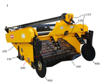
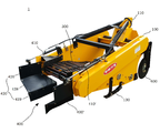
도 1은 본 발명의 제1실시 예에 의한 땅속작물 수확기의 전면부 사시 사진
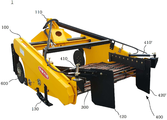
도 2는 본 발명의 제1실시 예에 의한 땅속작물 수확기의 배면부 사시 사진
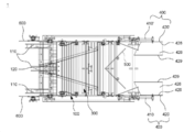
도 3은 본 발명의 제1실시 예에 의한 땅속작물 수확기의 배면부 사진
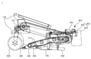
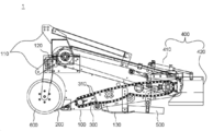
도 4는 본 발명의 제1실시 예에 의한 땅속작물 수확기의 측면도
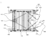
도 5는 본 발명의 제1실시 예에 의한 땅속작물 수확기의 평면도
도 6은 도 5에서 모음장치의 동작상태를 보인 것으로, (a)는 가운데로 모을 경우, (b)는 우측으로 모을 경우, (c)는 좌측으로 모을 경우
도 7은 본 발명의 제2실시 예에 의한 땅속작물 수확기의 배면부 사시 사진
도 8은 본 발명의 제2실시 예에 의한 땅속작물 수확기의 측면도
도 9는 본 발명의 제2실시 예에 의한 땅속작물 수확기의 평면도
도 10은 도 8에서 일측의 안내판이 들린 상태를 도시한 측면도
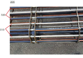
도 11은 이송부의 체인 봉에 연질호스가 끼워진 상태의 실물 사진이다.1 is a perspective view of the front part of the crop harvester under the ground according to the first embodiment of the present invention
Figure 2 is a perspective view of the rear portion of the crop harvester under the ground according to the first embodiment of the present invention
Figure 3 is a photograph of the rear part of the crop harvester under the ground according to the first embodiment of the present invention
Figure 4 is a side view of the crop harvester under the ground according to the first embodiment of the present invention
5 is a plan view of a crop harvester under the ground according to a first embodiment of the present invention
Figure 6 shows the operating state of the vowel device in Figure 5, (a) if it is collected in the middle, (b) when it is collected to the right, and (c) when it is collected to the left.
Figure 7 is a perspective view of the rear portion of the crop harvester under the ground according to a second embodiment of the present invention
Figure 8 is a side view of the crop harvester under the ground according to a second embodiment of the present invention
9 is a plan view of a crop harvester under the ground according to a second embodiment of the present invention
10 is a side view showing a state in which the guide plate on one side is lifted in FIG. 8;
11 is a real picture of a state where the soft hose is fitted to the chain rod of the transfer part.
이하, 본 발명을 한정하지 않는 바람직한 실시 예를 첨부된 도면에 의하여 상세히 설명하기로 한다.Hereinafter, preferred embodiments that do not limit the present invention will be described in detail with reference to the accompanying drawings.
도 1 내지 도 6에는 본 발명의 제1실시 예에 의한 땅속작물 수확기가 도시되어 있는데, 본 실시 예에서는 트랙터로 견인되는 프레임(100)의 전방 하부에 굴취부(200)가 형성되고 상기 굴취부(200)에서 굴취된 흙과 작물이 이송부(300)에 의해 후방 상부로 이송되면서 흙과 작물이 분리된 후 지면으로 작물이 낙하되도록 된 땅속작물 수확기에 있어서; 상기 프레임(100)의 후방에는 이송부(300)에서 이송된 작물을 가운데로 모으거나 좌,우의 어느 한 쪽으로 모아서 낙하시키기 위한 모음장치(400)가 구비된 것으로, 상기 모음장치(400)는 프레임(100)의 좌,우측에 각각 유압실린더(410,410')에 의해 좌우로 회동하는 안내판(420,420')의 선단이 힌지결합되어 상기 안내판(420,420')의 좌,우 회동조절에 의해 작물의 낙하 위치를 선정하도록 되어 있다.1 to 6, there is shown a crop harvester under the ground according to the first embodiment of the present invention. In this embodiment, the
본 실시 예에서, 상기 안내판(420,420')은 이송부(200) 상측의 중간위치에서 선단이 프레임(100)의 내측에 힌지결합되는 1차 안내부(422)와, 상기 1차 안내부(422)의 후방에서 이송부(200)의 후방 하부로 연장된 2차 안내부(424)로 구성되며, 상기 1차 안내부(422)의 내면은 작물과의 접촉시 표면 손상을 방지할 수 있도록 연질 소재로 이루어지고, 상기 2차 안내부(424)는 전체가 연질 소재로 이루어져 있다.In this embodiment, the
또, 상기 유압실린더(410,410')는 일단이 프레임(100)의 후단부에 힌지결합되고, 타단이 상기 안내판(420,420')의 1차 안내부(422) 중간부분에 힌지결합되어 유압실린더(410,410')의 신축동작에 의해 안내판(420,420')이 선단의 힌지결합부를 축으로 마치 물고기의 꼬리 지느러미 또는 선박의 키(러더)가 좌우로 움직일 수 있게 된다.In addition, one end of the
상기 프레임(100)의 전방에는 트랙터와 연결하기 위한 3점식 견인부(110)가 구비되어 있고, 중앙에는 트랙터의 동력을 전달받기 위한 축(120)이 구비되어 있으며, 이 축(120)에서 동력을 전달받아 이송부(300)가 구동되도록 되어 있는데, 이와 같은 땅속작물 수확기에서 동력전달계통의 구성은 기존의 땅속작물 수확기와 동일하므로 이에 대한 구체적인 설명은 생략하기로 한다.The front of the
또, 부호 130은 프레임(100)의 하부에 설치되는 스키로 프레임(100)이 안정적으로 주행할 수 있도록 보조하는 역할을 하게 된다.In addition,
상기 굴취부(200) 및 이송부(300)의 구성 또한 기존의 땅속작물 수확기와 동일하므로 이에 대한 설명도 생략하기로 하며, 다만 상기 이송부(300)는 도 11의 실물사진에서 알 수 있는 바와 같이, 체인 컨베이어 방식으로 이루어져 있고, 이 체인 컨베이어의 체인 봉(310)에는 연질의 연질호스(320)가 끼워져 작물의 표면손상을 방지함과 더불어 체인 봉(310) 사이의 간격을 좁혀 작은 작물도 체인 봉(310) 사이로 빠지지 않고 이송되도록 되어 있다.The configuration of the
상기 연질호스(320)는 인접하는 체인 봉(310) 모두에 설치할 수도 있으나, 도 1d의 실물사진에서와 같이 인접하는 체인 봉(310)을 하나씩 건너뛰어 설치함으로써 연질호스(320)가 끼워진 체인 봉과 연질호스가 끼워지지 않은 체인 봉 사이에 높낮이 차가 형성되어 후방 상부로 경사진 체인 컨베이어 위에 둥근 작물이 이송될 때 전방으로 굴러떨어지는 것을 방지하는 역할을 겸하도록 하는 것이 바람직하다.The
본 실시 예에서, 상기 모음장치(400)의 유압실린더(410,410')는 트랙터의 유압공급장치에 유압호스로 연결되어 작동되는데, 상기 유압실린더(410,410')는 복동식으로 이루어져 있고, 트랙터의 운전석에서 신축동작을 제어할 수 있도록 되어 있다.In this embodiment, the
또, 본 실시 예에서, 상기 이송부(200)의 하부에는 굴취된 작물이 떨어지는 지면에 홈을 파기 위한 골 형성날(500)이 높이조절 가능하게 부착되어 있는데, 이는 선단이 전방을 향하여 뾰죽하고 후방 외측을 향하여 벌어진 형태로 이루어져 있으며, 굴취부(200)에서 굴취된 두둑은 원래의 두둑 형태 즉, 중앙부가 높고 좌우측은 낮은 형태로 좌우로 경사지게 흙이 쌓이게 되는바, 굴취된 두둑 위에 작물이 떨어지게 되면 경사면을 따라 작물이 고랑으로 흘러내려갈 수 있으므로 상기 골 형성날(500)이 두둑의 가운데 부분을 상대적으로 낮게 골을 형성하게 됨으로써 지면으로 낙하되는 작물이 골에 떨어지게 되어 고랑으로 흘러내려가는 것을 효과적으로 방지할 수 있다.In addition, in this embodiment, the lower portion of the
또한, 본 실시 예에서, 상기 프레임(100)의 전방 양측에는 원판 날(600)이 프레임(100)의 선단에서 이격된 상태로 배치되어 있는데, 이 원판 날(600)은 두둑의 좌우 양측을 가르게 되면서 고랑 쪽으로 뻗은 줄기나 가지 및 잡초 등을 절단함과 동시에 두둑의 흙을 가르게 되므로 수확기의 프레임(100) 내측으로 진입하는 흙의 양을 제어하여 트랙터의 견인부하를 감소시킬 수 있도록 되어 있다.In addition, in the present embodiment, the front edge of the
한편, 상기 프레임(100)의 후방 내측 즉, 좌,우측 안내판(420,420')의 내측에는 이송부(300)의 후방 구동축 쪽으로 흙이 유입되는 것을 차단하기 위한 가드(140)가 경사지게 후방 내측을 향하여 경사지게 부착되어 있다.On the other hand, the rear inside of the
이와 같이 구성된 본 실시 예의 땅속작물 수확기는 도 6에 도시된 바와 같이 모음장치(400)를 다양하게 조작할 수 있는바, 도 6의 (a)에서와 같이 양측의 유압실린더(410,410')를 적정하게 신장시키면 안내판(420,420')이 후방 내측으로 모여지게 되어 이송부(300)를 따라 이송되어 오던 작물이 중앙으로 몰려서 낙하되게 되며, 도 6의 (b)에 도시된 바와 같이 좌측의 유압실린더(410')는 수축시키고, 우측의 유압실린더(410)를 신장시키면 좌측의 안내판(420')은 후방을 향하게 되고 우측의 안내판(420)은 내측을 향하게 되므로 이송부(300)로 이송되어 오던 작물이 좌측으로 몰리게 되면서 낙하게 되게 된다.The crop harvester of the present embodiment configured as described above can operate the
한편, 작물을 도 6의 (b)와는 반대로 즉, 우측으로 몰리도록 하고자 할 경우에는 도 6의 (c)와 같이 우측의 유압실린더(410)는 수축시키고, 좌측의 유압실린더(410')를 신장시키면 우측의 안내판(420)은 후방을 향하게 되고 좌측의 안내판(420')은 내측을 향하게 되므로 이송부(300)로 이송되어 오던 작물이 우측으로 몰리게 되면서 낙하게 되게 된다.On the other hand, as opposed to (b) of FIG. 6 (b), that is, in order to be driven to the right side, the
따라서, 본 실시 예의 땅속작물 수확기는 이송부(300)를 따라 이송되면서 흙과 분리된 작물이 두둑의 중앙으로 모여서 낙하되도록 하거나 좌측 또는 우측으로 몰려서 낙하되도록 할 수 있으므로 두둑의 폭이나 수확작업 방향에 따라서 모음장치의 방향을 선정하게 되면 트랙터의 바퀴가 수확된 작물을 짓밟게 되는 현상을 해소할 수 있으므로 연속적인 수확작업을 하는데 지장이 없게 되는 것은 물론, 작물이 좁은 간격으로 집중되어 낙하되므로 이의 수거작업 또한 효율적으로 할 수 있게 되는 것이다.Therefore, the crop harvester of the present embodiment may be transported along the conveying
도 7 내지 도 10에는 본 발명의 제2실시 예에 의한 땅속작물 수확기가 도시되어 있는데, 본 실시 예에서도 기본적인 구성 즉, 프레임의 후방에 모음장치(400)가 설치된 점에서는 상술한 제1실시 예와 동일하며, 다만 모음장치(400)를 구성하는 1쌍의 안내판(420,420')이 좌우로 회동동작하는 대신 상하로 회동하여 승강하도록 된 점에 차이가 있는바, 상기 모음장치(400)는 프레임(100)의 좌,우측에 각각 유압실린더(410,410')에 의해 상하로 회동하는 안내판(420,420')의 선단이 힌지결합되어 상기 안내판(420,420')의 상,하 회동조절에 의해 작물의 낙하위치를 선정하도록 되어 있다.7 to 10, the crop harvester is shown according to the second embodiment of the present invention. In this embodiment, the basic configuration, that is, the
본 실시 예에서, 상기 안내판(420,420')은 이송부(200)의 후단위치에서 선단이 프레임(100)의 내측에 힌지결합되는 1차 수직 안내부(426)와, 상기 1차 수직 안내부(426)의 하부에서 내측 하방으로 굴곡된 2차 경사 안내부(428)로 구성되며, 상기 1,2차 안내부(426,428)의 내면은 작물과의 접촉시 표면 손상을 방지할 수 있도록 연질 소재로 이루어져 있다.In the present embodiment, the
또, 상기 유압실린더(410,410')는 일단이 프레임(100)의 후단부에 힌지결합되고, 타단이 상기 안내판(420,420')의 1차 수직 안내부(426) 상측에 힌지결합되어 유압실린더(410,410')의 신축동작에 의해 안내판(420,420')이 선단의 힌지결합부를 축으로 상방향으로 들려서 이송부(300)의 후방과 간섭이 없는 상태를 유지하거나 하부로 내려져 이송부(300)에서 이송되어 하방으로 낙하하는 작물의 낙하방향을 변경시킬 수 있게 된다.In addition, one end of the
도면 중 부호 429는 상기 2차 경사 안내부(428)의 말단에서 하방으로 연장된 연장부로 낙하되는 작물이 지정된 하강위치 외곽으로 떨어지는 것을 방지함과 동시에 지면에 낙하될 때의 충격을 완화시키는 역할을 하게 된다.
이와 같이 구성된 본 실시 예의 땅속작물 수확기는 좌,우측의 안내판(420)을 모두 하방으로 내린 상태(도 8 및 도 9 참조)에서 굴취를 하게 되면 이송부(300)를 따라 후방으로 이송되면서 흙과 분리된 작물이 두둑의 중앙으로 모이게 되며, 도 10에 도시된 바와 같이 좌,우측의 안내판(420,420') 중의 어느 하나를 들어올리게 되면(도면상에서는 양측의 안내판을 모두 들어올린 상태로 도시됨) 들어올린 방향으로 수확물이 집중적으로 낙하되게 되는바, 후방 하부로로 내려져 있는 안내판(420 또는 420')에 의해 후방으로 이송된 작물이 지면으로 낙하되다가 2차 경사 안내부(428)에서 충돌된 후 지면으로 떨어지게 되므로 안내판(420,420')이 들려진 위치로 작물이 몰리면서 떨어지게 되는 것이다.Underground crop harvester of the present embodiment configured as described above is separated from the soil while being transported rearward along the
한편, 본 실시 예에서는 좌,우측의 안내판(420,420')을 모두 들어올린 상태를 유지할 수 있으므로 두둑의 전 면적에 걸쳐 작물을 낙하시킬 필요가 있을 경우에는 이와 같은 상태로 수확작업을 실시하면 되며, 이동시에도 수확기의 전장(길이)를 줄일 수 있도록 좌,우측의 안내판(420,420')을 모두 들어 올린 상태가 되도록 할 수 있다.On the other hand, in this embodiment, since the left and
이상 설명한 바와 같이 본 발명에 의하면 프레임 전방의 굴취부에서 굴취된 작물이 이송부를 따라 후방 상부로로 이송되면서 흙과 분리된 후 지면에 낙하될 때, 좌우측의 안내판 방향을 조절하는 것에 의해 작물의 낙하 위치를 두둑의 중앙으로 모으거나 좌우의 어느 한 쪽으로 몰아줄 수 있으므로 인접하는 두둑의 연속적인 굴취작업시 트랙터 바퀴에 의해 굴취된 작물이 짓밟히거나 손상되는 것을 방지할 수 있음과 아울러 굴취된 작물의 수거작업효율 또한 향상시킬 수 있고, 이송부의 하부에 높낮이 조절 가능하게 설치된 골 형성날에 의해 낙하되는 작물이 고랑으로 흘러내려가는 것을 방지할 수 있으며, 이송부의 체인 봉에 끼워진 연질 호스에 의해 작물의 표면이 보호받게 됨은 물론 후방 상부로 이송 중에 전방으로 굴러내려오는 것을 방지할 수 있으며, 프레임 전방에 프레임과 이격되도록 설치된 원판 날에 의해 골의 양측 흙을 가르고 작물의 줄기나 뿌리를 절단해내게 되므로 트랙터의 견인부하 또한 감소시킴으로써 땅속작물의 수확작업을 효율적으로 할 수 있는 이점이 있다.As described above, according to the present invention, when the crop excavated from the excavation part in front of the frame is transferred to the rear upper part along the transport part and is separated from the soil and then falls to the ground, the crop of the left and right sides is adjusted by adjusting the direction of the guide plate. Since the location can be gathered to the center of the ridge or driven to either side of the left and right sides, it is possible to prevent the crop crushed by the tractor wheel from being trampled or damaged during the continuous crushing operation of the adjacent ridge. The collection efficiency can also be improved, and crops falling by the bone-forming blades, which can be height-adjusted in the lower part of the conveying part, can be prevented from flowing down into the furrow, and the surface of the crop is made by the soft hose inserted into the chain rod of the conveying part. As well as being protected, it can be prevented from rolling forward while transporting to the rear upper part, and a tractor blade is used to cut the soil on both sides of the bone and cut the stem or root of the crop by the disc blade installed to be separated from the frame in front of the frame. It also has the advantage of efficiently harvesting the crops under the ground by reducing the traction load of the plant.
1 : 땅속작물 수확기
100 : 프레임
110 : 견인부
120 : 동력전달축
130 : 스키
140 : 가드
200 : 굴취부
300 : 이송부
310 : 체인 봉
320 : 연질호스
400 : 모음장치
410,410' : 유압실린더
420,420' : 안내판
422 : 1차 안내부
424 : 2차 안내부
426 : 1차 수직 안내부
428 : 2차 경사 안내부
429 : 연장부
500 : 골 형성날
600 : 원판 날1: Underground crop harvester
100: frame
110: towing unit
120: power transmission shaft
130: ski
140: guard
200: excavation part
300: transfer unit
310: chain rod
320: soft hose
400: vowel device
410,410': Hydraulic cylinder
420,420': Information board
422: 1st guide
424: 2nd information guide
426: 1st vertical guide
428: Second slope guide
429: Extension
500: bone formation day
600: original blade
Claims (11)
상기 프레임(100)의 후방에는 이송부(300)에서 이송된 작물을 가운데로 모으거나 좌우의 어느 한 쪽으로 모아서 낙하시키기 위한 모음장치(400)가 구비된 것을 특징으로 하는 땅속작물 수확기.
The excavation part 200 is formed at the front lower portion of the frame 100 to be pulled by the tractor, and the soil and the crop excavated from the excavation part 200 are transferred to the rear upper part by the transport part 300 so that the soil and the crop are separated. In the crop harvester that the crops fall to the ground afterwards,
In the rear of the frame 100, the crop harvester 400 is provided with a collection device 400 for collecting the crops transferred from the transfer part 300 to the center or collecting them to either side of the left and right sides.
상기 모음장치(400)는 프레임(100)의 좌우측에 각각 유압실린더(410,410')에 의해 좌우로 회동하는 안내판(420,420')의 선단이 힌지결합되어 상기 안내판(420,420')의 좌우 회동조절에 의해 작물의 낙하 위치를 선정하도록 된 것을 특징으로 하는 작물 모음장치가 구비된 땅속작물 수확기.
The method according to claim 1,
The collection device 400 is hingedly coupled to the front and rear ends of the guide plates 420 and 420', which are rotated left and right by hydraulic cylinders 410 and 410', respectively, on the left and right sides of the frame 100, thereby controlling the left and right rotation of the guide plates 420 and 420'. Crop harvester equipped with a crop collection device, characterized in that to select the location of the crop fall.
상기 모음장치(400)는 프레임(100)의 좌우측에 각각 유압실린더(410,410')에 의해 상하로 회동하는 안내판(420,420')의 선단이 힌지결합되어 상기 안내판(420,420')의 상하 회동조절에 의해 작물의 낙하위치를 선정하도록 된 것을 특징으로 하는 작물 모음장치가 구비된 땅속작물 수확기.
The method according to claim 1,
The collection device 400 is hingedly coupled to the front and rear ends of the guide plates 420 and 420', which are rotated up and down by hydraulic cylinders 410 and 410', respectively, on the left and right sides of the frame 100, thereby controlling the up and down rotation of the guide plates 420 and 420'. Crop harvester equipped with a crop collection device, characterized in that to select the location of the crop fall.
상기 안내판(420,420')은 이송부(200) 상측의 중간위치에서 선단이 프레임(100)의 내측에 힌지결합되는 1차 안내부(422)와, 상기 1차 안내부(422)의 후방에서 이송부(200)의 후방 하부로 연장된 2차 안내부(424)로 구성되며, 상기 1차 안내부(422)의 내면은 작물과의 접촉시 표면 손상을 방지할 수 있도록 연질 소재로 이루어지고, 상기 2차 안내부(424)는 전체가 연질 소재로 이루어진 것을 특징으로 하는 작물 모음장치가 구비된 땅속작물 수확기.
The method according to claim 2,
The guide plates 420 and 420' include a primary guide portion 422 whose tip is hinged to the inner side of the frame 100 at an intermediate position above the transfer portion 200, and a transfer portion at the rear of the primary guide portion 422 ( It consists of a secondary guide portion 424 extending to the rear lower portion of the 200), the inner surface of the primary guide portion 422 is made of a soft material to prevent surface damage upon contact with the crop, the 2 The car guide unit 424 is an underground crop harvester equipped with a crop collection device, characterized in that the whole is made of soft material.
상기 안내판(420,420')은 이송부(200)의 후단위치에서 선단이 프레임(100)의 내측에 힌지결합되는 1차 수직 안내부(426)와, 상기 1차 수직 안내부(426)의 하부에서 내측 하방으로 굴곡된 2차 경사 안내부(428)로 구성되며, 상기 1,2차 안내부(426,428)의 내면은 작물과의 접촉시 표면 손상을 방지할 수 있도록 연질 소재로 이루어진 것을 특징으로 하는 작물 모음장치가 구비된 땅속작물 수확기.
The method according to claim 3,
The guide plates 420 and 420' have a primary vertical guide portion 426 whose tip is hinged to the inner side of the frame 100 at a rear unit value of the transfer portion 200, and an inner side from the lower portion of the primary vertical guide portion 426. It is composed of a second inclined guide portion 428 curved downward, and the inner surface of the first and second guide portions 426,428 is made of a soft material so as to prevent surface damage upon contact with the crop. Underground crop harvester with collection device.
상기 이송부(200)의 하부에는 굴취된 작물이 떨어지는 지면에 홈을 파기 위한 홈파기 날(500)이 부착된 것을 특징으로 하는 작물 모음장치가 구비된 땅속작물 수확기.
The method according to any one of claims 1 to 5,
A bottom crop harvester equipped with a crop collection device, characterized in that a groove digging blade (500) for digging a groove on the ground where the excavated crop falls is attached to the lower portion of the transfer part (200).
상기 홈파기 날(500)은 선단이 전방을 향하여 뾰죽하고 후방 외측을 향하여 벌어진 형태로 이루어진 것을 특징으로 하는 작물 모음장치가 구비된 땅속작물 수확기.
The method according to claim 6,
The grooving blade 500 is a crop harvester equipped with a crop collection device, characterized in that the tip is pointed toward the front and flared toward the rear outside.
상기 홈파기 날(500)은 높낮이 조절이 이루어지는 것을 특징으로 하는 작물 모음장치가 구비된 땅속작물 수확기.
The method according to claim 6,
The digging blade 500 is a crop harvester equipped with a crop collection device characterized in that the height is adjusted.
상기 프레임(100)의 전방 양측에는 원판 날(600)이 프레임(100)의 선단에서 이격된 상태로 배치된 것을 특징으로 하는 작물 모음장치가 구비된 땅속작물 수확기.
The method according to any one of claims 1 to 5,
Underground crop harvester equipped with a crop collection device, characterized in that the disk blades (600) are arranged at a distance from the front end of the frame (100) on both front sides of the frame (100).
상기 이송부(300)는 체인 컨베이어 방식으로 이루어지고, 체인봉에 연질의 연질호스가 끼워진 것을 특징으로 하는 작물 모음장치가 구비된 땅속작물 수확기.
The method according to any one of claims 1 to 5,
The transfer unit 300 is made of a chain conveyor method, the crop harvester is equipped with a crop collection device, characterized in that a soft flexible hose is fitted to the chain rod.
상기 연질호스(320)는 인접하는 체인봉(310)을 하나씩 건너뛰어 설치하는 것을 특징으로 하는 작물 모음장치가 구비된 땅속작물 수확기.The method according to claim 10,
The soft hose 320 is a crop harvester equipped with a crop collection device characterized in that the adjacent chain rods 310 are skipped one by one.
Priority Applications (1)
| Application Number | Priority Date | Filing Date | Title |
|---|---|---|---|
| KR1020180151516A KR20200065238A (en) | 2018-11-30 | 2018-11-30 | An Underground crop harvester equipped with gathering device |
Applications Claiming Priority (1)
| Application Number | Priority Date | Filing Date | Title |
|---|---|---|---|
| KR1020180151516A KR20200065238A (en) | 2018-11-30 | 2018-11-30 | An Underground crop harvester equipped with gathering device |
Publications (1)
| Publication Number | Publication Date |
|---|---|
| KR20200065238A true KR20200065238A (en) | 2020-06-09 |
Family
ID=71082249
Family Applications (1)
| Application Number | Title | Priority Date | Filing Date |
|---|---|---|---|
| KR1020180151516A KR20200065238A (en) | 2018-11-30 | 2018-11-30 | An Underground crop harvester equipped with gathering device |
Country Status (1)
| Country | Link |
|---|---|
| KR (1) | KR20200065238A (en) |
Cited By (3)
| Publication number | Priority date | Publication date | Assignee | Title |
|---|---|---|---|---|
| KR102267958B1 (en) * | 2021-01-25 | 2021-06-22 | 주식회사 불스 | Harvest apparatus for garlic |
| CN113853920A (en) * | 2021-11-12 | 2021-12-31 | 山东思代尔农业装备有限公司 | Light and simple crawler self-propelled potato harvester |
| KR20220054991A (en) * | 2020-10-26 | 2022-05-03 | 대한민국(농촌진흥청장) | Bulbous plant harvesting machine |
Citations (4)
| Publication number | Priority date | Publication date | Assignee | Title |
|---|---|---|---|---|
| KR200479214Y1 (en) | 2014-12-23 | 2016-01-04 | 노술해 | Foldable harvester for bulbs |
| KR20160035844A (en) | 2014-09-24 | 2016-04-01 | 김재동 | Worker boarding type root crop harvester |
| KR101771239B1 (en) | 2017-04-06 | 2017-08-25 | 주식회사 죽암기계 | Bulbous plant harvesting machine |
| KR101824221B1 (en) | 2015-10-16 | 2018-03-14 | 노술해 | Bulbs harvesters equipped with a dirt removing conveyor |
-
2018
- 2018-11-30 KR KR1020180151516A patent/KR20200065238A/en not_active Application Discontinuation
Patent Citations (4)
| Publication number | Priority date | Publication date | Assignee | Title |
|---|---|---|---|---|
| KR20160035844A (en) | 2014-09-24 | 2016-04-01 | 김재동 | Worker boarding type root crop harvester |
| KR200479214Y1 (en) | 2014-12-23 | 2016-01-04 | 노술해 | Foldable harvester for bulbs |
| KR101824221B1 (en) | 2015-10-16 | 2018-03-14 | 노술해 | Bulbs harvesters equipped with a dirt removing conveyor |
| KR101771239B1 (en) | 2017-04-06 | 2017-08-25 | 주식회사 죽암기계 | Bulbous plant harvesting machine |
Cited By (3)
| Publication number | Priority date | Publication date | Assignee | Title |
|---|---|---|---|---|
| KR20220054991A (en) * | 2020-10-26 | 2022-05-03 | 대한민국(농촌진흥청장) | Bulbous plant harvesting machine |
| KR102267958B1 (en) * | 2021-01-25 | 2021-06-22 | 주식회사 불스 | Harvest apparatus for garlic |
| CN113853920A (en) * | 2021-11-12 | 2021-12-31 | 山东思代尔农业装备有限公司 | Light and simple crawler self-propelled potato harvester |
Similar Documents
| Publication | Publication Date | Title |
|---|---|---|
| US6539697B2 (en) | Apparatus and method for knocking down and crushing farm crop residue | |
| US4482019A (en) | Earth surface cleaning machine | |
| CN202603209U (en) | Pull-type twin-row potato harvester | |
| US5024052A (en) | Apparatus for harvesting berries on low plants | |
| KR20200065238A (en) | An Underground crop harvester equipped with gathering device | |
| US4261163A (en) | Method and apparatus for harvesting produce on plastic mulch beds | |
| KR102136607B1 (en) | Underground crop harvester | |
| KR101741125B1 (en) | furrow growing root crops harvesters | |
| US5379577A (en) | Cane harvester and method | |
| KR102361293B1 (en) | Stem cutting device for harvesting dry crops | |
| US4015667A (en) | Cotton stalk and root shredder with re-bedder | |
| US10455762B1 (en) | Sugar beet harvest apparatus | |
| KR102556707B1 (en) | Stem cutting device for harvesting dry crops | |
| KR102201118B1 (en) | Flattening device for harvester | |
| US3986463A (en) | Agricultural implement | |
| US10470353B2 (en) | Rock collection and rock rowing device | |
| US3880099A (en) | Agricultural implement | |
| KR100194999B1 (en) | Tuber crop harvester | |
| US9204589B2 (en) | Device and method for separating plant material from a bed of plants | |
| KR102471983B1 (en) | A collection type bulb crop extractor for tractors | |
| CA2926833C (en) | Rock collection and rock rowing device | |
| RU195156U1 (en) | Potato digger | |
| KR102217750B1 (en) | Self-moving type welsh onion harvester | |
| US4282932A (en) | Rock picker | |
| RU2765501C1 (en) | Potato digger |
Legal Events
| Date | Code | Title | Description |
|---|---|---|---|
| E902 | Notification of reason for refusal | ||
| E902 | Notification of reason for refusal | ||
| E601 | Decision to refuse application |