KR20200032031A - Method and apparatus for manufacturing riblets - Google Patents
Method and apparatus for manufacturing riblets Download PDFInfo
- Publication number
- KR20200032031A KR20200032031A KR1020197033205A KR20197033205A KR20200032031A KR 20200032031 A KR20200032031 A KR 20200032031A KR 1020197033205 A KR1020197033205 A KR 1020197033205A KR 20197033205 A KR20197033205 A KR 20197033205A KR 20200032031 A KR20200032031 A KR 20200032031A
- Authority
- KR
- South Korea
- Prior art keywords
- riblets
- laser
- partial beams
- manufacturing
- deflection
- Prior art date
Links
- 238000000034 method Methods 0.000 title claims abstract description 45
- 238000004519 manufacturing process Methods 0.000 title claims abstract description 41
- 238000000059 patterning Methods 0.000 claims abstract description 8
- 230000002452 interceptive effect Effects 0.000 claims description 76
- 239000011247 coating layer Substances 0.000 claims description 71
- 230000005855 radiation Effects 0.000 claims description 65
- 238000012545 processing Methods 0.000 claims description 58
- 238000000576 coating method Methods 0.000 claims description 50
- 239000011248 coating agent Substances 0.000 claims description 45
- 230000003287 optical effect Effects 0.000 claims description 44
- 238000003754 machining Methods 0.000 claims description 40
- 230000008859 change Effects 0.000 claims description 32
- 230000000737 periodic effect Effects 0.000 claims description 17
- 238000010521 absorption reaction Methods 0.000 claims description 12
- NIXOWILDQLNWCW-UHFFFAOYSA-N acrylic acid group Chemical group C(C=C)(=O)O NIXOWILDQLNWCW-UHFFFAOYSA-N 0.000 claims description 5
- 239000010410 layer Substances 0.000 description 30
- 239000000463 material Substances 0.000 description 25
- 230000000875 corresponding effect Effects 0.000 description 17
- 239000004814 polyurethane Substances 0.000 description 17
- 229920002635 polyurethane Polymers 0.000 description 17
- 238000009826 distribution Methods 0.000 description 16
- 230000015572 biosynthetic process Effects 0.000 description 15
- 230000008569 process Effects 0.000 description 9
- 230000007423 decrease Effects 0.000 description 8
- 230000009471 action Effects 0.000 description 6
- 238000010586 diagram Methods 0.000 description 6
- 230000000295 complement effect Effects 0.000 description 5
- 230000001419 dependent effect Effects 0.000 description 5
- 239000000975 dye Substances 0.000 description 5
- 238000000608 laser ablation Methods 0.000 description 5
- 239000002313 adhesive film Substances 0.000 description 4
- 230000008901 benefit Effects 0.000 description 4
- 238000011161 development Methods 0.000 description 4
- 238000009434 installation Methods 0.000 description 4
- 239000004071 soot Substances 0.000 description 4
- 238000002835 absorbance Methods 0.000 description 3
- 238000006243 chemical reaction Methods 0.000 description 3
- 238000010276 construction Methods 0.000 description 3
- 238000009792 diffusion process Methods 0.000 description 3
- 230000000694 effects Effects 0.000 description 3
- 239000003973 paint Substances 0.000 description 3
- 238000010422 painting Methods 0.000 description 3
- 230000009467 reduction Effects 0.000 description 3
- 239000004593 Epoxy Substances 0.000 description 2
- 229910010413 TiO 2 Inorganic materials 0.000 description 2
- GWEVSGVZZGPLCZ-UHFFFAOYSA-N Titan oxide Chemical compound O=[Ti]=O GWEVSGVZZGPLCZ-UHFFFAOYSA-N 0.000 description 2
- 238000013459 approach Methods 0.000 description 2
- 238000004364 calculation method Methods 0.000 description 2
- 230000001427 coherent effect Effects 0.000 description 2
- 239000003822 epoxy resin Substances 0.000 description 2
- 230000005284 excitation Effects 0.000 description 2
- 238000002474 experimental method Methods 0.000 description 2
- 239000012530 fluid Substances 0.000 description 2
- 239000000446 fuel Substances 0.000 description 2
- 238000005259 measurement Methods 0.000 description 2
- 238000002844 melting Methods 0.000 description 2
- 230000008018 melting Effects 0.000 description 2
- 229910052751 metal Inorganic materials 0.000 description 2
- 239000002184 metal Substances 0.000 description 2
- 238000005498 polishing Methods 0.000 description 2
- 229920000647 polyepoxide Polymers 0.000 description 2
- 230000008092 positive effect Effects 0.000 description 2
- 229920006268 silicone film Polymers 0.000 description 2
- 230000002123 temporal effect Effects 0.000 description 2
- 241000282472 Canis lupus familiaris Species 0.000 description 1
- 241000251730 Chondrichthyes Species 0.000 description 1
- RYGMFSIKBFXOCR-UHFFFAOYSA-N Copper Chemical compound [Cu] RYGMFSIKBFXOCR-UHFFFAOYSA-N 0.000 description 1
- XUIMIQQOPSSXEZ-UHFFFAOYSA-N Silicon Chemical compound [Si] XUIMIQQOPSSXEZ-UHFFFAOYSA-N 0.000 description 1
- 229910000831 Steel Inorganic materials 0.000 description 1
- 238000005299 abrasion Methods 0.000 description 1
- 238000000862 absorption spectrum Methods 0.000 description 1
- 239000002318 adhesion promoter Substances 0.000 description 1
- 230000002411 adverse Effects 0.000 description 1
- 230000004888 barrier function Effects 0.000 description 1
- 230000005540 biological transmission Effects 0.000 description 1
- 229910052802 copper Inorganic materials 0.000 description 1
- 239000010949 copper Substances 0.000 description 1
- 238000005260 corrosion Methods 0.000 description 1
- 238000000354 decomposition reaction Methods 0.000 description 1
- 230000001066 destructive effect Effects 0.000 description 1
- 239000006185 dispersion Substances 0.000 description 1
- 230000009977 dual effect Effects 0.000 description 1
- 239000000428 dust Substances 0.000 description 1
- 238000005516 engineering process Methods 0.000 description 1
- 238000009533 lab test Methods 0.000 description 1
- 210000004185 liver Anatomy 0.000 description 1
- 238000012423 maintenance Methods 0.000 description 1
- 150000002739 metals Chemical class 0.000 description 1
- 239000002245 particle Substances 0.000 description 1
- 230000021715 photosynthesis, light harvesting Effects 0.000 description 1
- 229920003023 plastic Polymers 0.000 description 1
- 239000004033 plastic Substances 0.000 description 1
- 230000010287 polarization Effects 0.000 description 1
- 229920000642 polymer Polymers 0.000 description 1
- 229920001296 polysiloxane Polymers 0.000 description 1
- 239000011527 polyurethane coating Substances 0.000 description 1
- 238000003825 pressing Methods 0.000 description 1
- 230000002787 reinforcement Effects 0.000 description 1
- 230000008439 repair process Effects 0.000 description 1
- 229920005989 resin Polymers 0.000 description 1
- 239000011347 resin Substances 0.000 description 1
- 238000000926 separation method Methods 0.000 description 1
- 229910052710 silicon Inorganic materials 0.000 description 1
- 239000010703 silicon Substances 0.000 description 1
- 230000003595 spectral effect Effects 0.000 description 1
- 239000010959 steel Substances 0.000 description 1
- 239000000126 substance Substances 0.000 description 1
- 230000009182 swimming Effects 0.000 description 1
- 239000004408 titanium dioxide Substances 0.000 description 1
- 238000013519 translation Methods 0.000 description 1
Images


Classifications
-
- B—PERFORMING OPERATIONS; TRANSPORTING
- B23—MACHINE TOOLS; METAL-WORKING NOT OTHERWISE PROVIDED FOR
- B23K—SOLDERING OR UNSOLDERING; WELDING; CLADDING OR PLATING BY SOLDERING OR WELDING; CUTTING BY APPLYING HEAT LOCALLY, e.g. FLAME CUTTING; WORKING BY LASER BEAM
- B23K26/00—Working by laser beam, e.g. welding, cutting or boring
- B23K26/352—Working by laser beam, e.g. welding, cutting or boring for surface treatment
- B23K26/355—Texturing
-
- B—PERFORMING OPERATIONS; TRANSPORTING
- B23—MACHINE TOOLS; METAL-WORKING NOT OTHERWISE PROVIDED FOR
- B23K—SOLDERING OR UNSOLDERING; WELDING; CLADDING OR PLATING BY SOLDERING OR WELDING; CUTTING BY APPLYING HEAT LOCALLY, e.g. FLAME CUTTING; WORKING BY LASER BEAM
- B23K26/00—Working by laser beam, e.g. welding, cutting or boring
- B23K26/02—Positioning or observing the workpiece, e.g. with respect to the point of impact; Aligning, aiming or focusing the laser beam
- B23K26/06—Shaping the laser beam, e.g. by masks or multi-focusing
- B23K26/067—Dividing the beam into multiple beams, e.g. multifocusing
- B23K26/0676—Dividing the beam into multiple beams, e.g. multifocusing into dependently operating sub-beams, e.g. an array of spots with fixed spatial relationship or for performing simultaneously identical operations
-
- B—PERFORMING OPERATIONS; TRANSPORTING
- B23—MACHINE TOOLS; METAL-WORKING NOT OTHERWISE PROVIDED FOR
- B23K—SOLDERING OR UNSOLDERING; WELDING; CLADDING OR PLATING BY SOLDERING OR WELDING; CUTTING BY APPLYING HEAT LOCALLY, e.g. FLAME CUTTING; WORKING BY LASER BEAM
- B23K26/00—Working by laser beam, e.g. welding, cutting or boring
- B23K26/08—Devices involving relative movement between laser beam and workpiece
-
- B—PERFORMING OPERATIONS; TRANSPORTING
- B23—MACHINE TOOLS; METAL-WORKING NOT OTHERWISE PROVIDED FOR
- B23K—SOLDERING OR UNSOLDERING; WELDING; CLADDING OR PLATING BY SOLDERING OR WELDING; CUTTING BY APPLYING HEAT LOCALLY, e.g. FLAME CUTTING; WORKING BY LASER BEAM
- B23K26/00—Working by laser beam, e.g. welding, cutting or boring
- B23K26/352—Working by laser beam, e.g. welding, cutting or boring for surface treatment
- B23K26/3568—Modifying rugosity
- B23K26/3584—Increasing rugosity, e.g. roughening
-
- B—PERFORMING OPERATIONS; TRANSPORTING
- B23—MACHINE TOOLS; METAL-WORKING NOT OTHERWISE PROVIDED FOR
- B23K—SOLDERING OR UNSOLDERING; WELDING; CLADDING OR PLATING BY SOLDERING OR WELDING; CUTTING BY APPLYING HEAT LOCALLY, e.g. FLAME CUTTING; WORKING BY LASER BEAM
- B23K26/00—Working by laser beam, e.g. welding, cutting or boring
- B23K26/36—Removing material
-
- B—PERFORMING OPERATIONS; TRANSPORTING
- B64—AIRCRAFT; AVIATION; COSMONAUTICS
- B64C—AEROPLANES; HELICOPTERS
- B64C21/00—Influencing air flow over aircraft surfaces by affecting boundary layer flow
- B64C21/10—Influencing air flow over aircraft surfaces by affecting boundary layer flow using other surface properties, e.g. roughness
-
- B—PERFORMING OPERATIONS; TRANSPORTING
- B64—AIRCRAFT; AVIATION; COSMONAUTICS
- B64C—AEROPLANES; HELICOPTERS
- B64C2230/00—Boundary layer controls
- B64C2230/26—Boundary layer controls by using rib lets or hydrophobic surfaces
-
- Y—GENERAL TAGGING OF NEW TECHNOLOGICAL DEVELOPMENTS; GENERAL TAGGING OF CROSS-SECTIONAL TECHNOLOGIES SPANNING OVER SEVERAL SECTIONS OF THE IPC; TECHNICAL SUBJECTS COVERED BY FORMER USPC CROSS-REFERENCE ART COLLECTIONS [XRACs] AND DIGESTS
- Y02—TECHNOLOGIES OR APPLICATIONS FOR MITIGATION OR ADAPTATION AGAINST CLIMATE CHANGE
- Y02E—REDUCTION OF GREENHOUSE GAS [GHG] EMISSIONS, RELATED TO ENERGY GENERATION, TRANSMISSION OR DISTRIBUTION
- Y02E10/00—Energy generation through renewable energy sources
- Y02E10/70—Wind energy
- Y02E10/72—Wind turbines with rotation axis in wind direction
Abstract
본 발명은 리블렛들(1)의 제조 방법 및 장치에 관한 것으로, 리블렛들(1)은 레이저 간섭 구조화 또는 DLIP -Direct Laser Interference Patterning(직접 레이저 간섭 패터닝) - 를 이용하여 특히 이미 도장 및 경화된 표면에 도입된다. 또한, 본 발명은 이러한 방식으로 제조된 리블렛들을 포함하는 부품에 관한 것이다. 이러한 방식으로 항공기, 선박 및 풍력 발전 설비가 보다 낮은 유동 저항으로 구동될 수 있다.The present invention relates to a method and apparatus for manufacturing the riblets (1), the riblets (1) are already already painted and cured using a laser interference structuring or DLIP-Direct Laser Interference Patterning (direct laser interference patterning)- Is introduced to the surface. The invention also relates to a part comprising riblets manufactured in this way. In this way, aircraft, ships and wind power plants can be driven with lower flow resistance.
Description
본 발명은 리블렛의 제조 방법 및 장치 및 이에 상응하여 제조될 수 있는 리블렛을 포함하는 부품에 관한 것이다.The present invention relates to a method and apparatus for manufacturing a riblet and a component comprising a riblet which can be produced correspondingly.
난류 유동에서 표면의 마찰을 리블렛을 통해 줄일 수 있다는 것은 약 30년전부터 공지되어 있다. "작은 리브" 또는 "미세 리브"를 나타내는 영단어에서 개념성을 차용한 것으로 유체 역학의 분야에서 통상적 전문 개념으로 구축된 리블렛은 특히 빠르게 헤엄칠 때의 상어에서 주로 매우 미세한 고랑, 또는 끝단이 매우 날카로운 리브를 갖는 비늘의 표면 형상을 연구하다가 발견된 것이다. 매끄러운 표면에 비해, 리블렛을 이용하면 유동 저항을 주로 최대 10% 만큼 감소시킬 수 있는데, 이에 대해 기본적으로 적용되는 것은, 리블렛의 크기가 매질 및 유동 속도에 맞게 조정되고, 또한, 리블렛의 리브들이 첨예하게 형성될수록, 유동 저항의 가능한 감소량도 증가한다는 것이다.It has been known about 30 years ago that the friction of a surface in turbulent flow can be reduced through riblets. The concept of borrowing conceptuality from English words representing "small ribs" or "fine ribs," and the riblets, which are established as a common professional concept in the field of fluid mechanics, have very fine furrows, or very large tails, especially in sharks when swimming rapidly. It was discovered while studying the surface shape of scales with sharp ribs. Compared to smooth surfaces, the use of riblets can mainly reduce the flow resistance by up to 10%, the basic application of which is that the size of the riblets is adapted to the medium and flow rate, and also, The sharper the ribs are formed, the more the reduction in flow resistance is possible.
장거리용 항공기는 대부분 거의 일정한 상대 속도로 비행하고, 풍력 발전 설비는 좁은 회전수 범위에서 구동되며, 무역용 선박은 일정한 항해 속도로 긴 항로를 운행한다. 따라서 이러한 경우들에서 적합한 리블렛에 의한 긍정적 효과를 기대할 수 있다. 유체 역학적 계산 및 연구실 실험을 통하여, 이 모든 경우에 매우 상이한 적용 방식에도 불구하고 리블렛의 크기는 40 ㎛- 200 ㎛의 범위에 있는 것이 적합하다는 점이 획기적으로 확인되었다. 그러나 최적값은 기본적으로 특정한 사용 조건에 맞게 조정되어야 할 것이다. 편차가 커지면 긍정적 효과는 감소할 수 있고, 더욱이 상황에 따라 역효과가 날 수 있다.Most long-haul aircraft fly at almost constant relative speeds, wind power plants operate in a narrow range of revolutions, and trade vessels operate long routes at constant voyages. Therefore, in these cases, a positive effect by a suitable riblet can be expected. Through hydrodynamic calculations and laboratory experiments, it has been found that, in all these cases, it is suitable that the size of the riblets is suitable in the range of 40 μm-200 μm, despite very different application methods. However, the optimum value should basically be adjusted to the specific conditions of use. As the deviation increases, the positive effect may decrease, and further adversely, depending on the situation.
항공기, 선박, 및 풍력 터빈의 로터 블레이드와 같이 구동 시 유동에 노출되도록 구성된 다른 부품에서도 리블렛의 유체 공학적 이점을 활용할 수 있도록, 미세한 리블렛 구조물을 경제적으로 허용 가능한 가공 시간 내에 대면적으로 적용할 수 있는 것이 바람직하다.Fine riblet structures can be applied in a large area within economically acceptable machining times to take advantage of the fluid engineering advantages of the riblets in other components configured to be exposed to flow during operation, such as rotor blades of aircraft, ships, and wind turbines. It is desirable to be able to.
현재 공지된 방법으로서, 각인된 리블렛 구조를 포함하는 접착 필름을 항공기 표면에 접착하는 것이 있다. 그러나 이러한 방법에서는 리블렛의 리브들이 제한적으로만 첨예하게 제공될 수 있어서, 리블렛에 의한 유동 저항의 잠재적 감소 성능이 일반적으로 비교적 낮은 수준으로만 사용될 수 있다. 또한, 일반 도장에 비해 각인형 접착 필름은 상대적으로 두껍고 무겁기 때문에 접착된 부품의 중량이 증가하게 된다. 그 밖에도, 접착 필름은 수리 작업 또는 재도장 시 수작업으로 제거해야 해서 비용이 든다.As a currently known method, there is a method of adhering an adhesive film containing an imprinted riblet structure to an aircraft surface. However, in this method, the riblets of the riblets can only be provided with limited sharpness, so that the potential reduction performance of the flow resistance by the riblets can generally only be used at relatively low levels. In addition, compared to the general coating, the imprinted adhesive film is relatively thick and heavy, so the weight of the bonded component increases. In addition, the adhesive film is expensive because it has to be removed manually during repair or repainting.
항공기 표면에 리블렛을 제조하기 위한 또 다른 공지된 방법은 항공기 표면을 위한 특정한 도장계, 아직 경화되지 않은 도장물에 리블렛 구조를 각인하기 위한 원주형 실리콘 스트립 및 이러한 방식으로 각인된 표면을 이후에 UV광으로 경화하는 것에 기반한다. 리블렛 구조는 음각 상으로서 실리콘 필름 내에 각인된다. 실리콘 필름은 항공기 표면에 점착되고, 새로 도포되어 아직 연성인 도장 층에 구조를 전사한다. 추가적으로, 완전히 가교 결합되어 운항 중에 필요한 인성(toughness) 및 내마모도를 달성하기 위해, 이와 같이 리블렛을 포함하여 형성되는 항공기 표면은 일반적으로 수 시간 동안 실온에서 더 경화되어야 한다. 그러나 이러한 방법은 매우 비용이 들고 오류에 취약한데, 일반적으로 좁게 한정되는 가압력에 의해 실리콘 필름은 부분적으로 자유형으로 형성되는 항공기 표면에 걸쳐 바람직하게는 정확히 평행한 경로에서 안내되어야 하기 때문이다. 분당 약 1 평방미터의 가공 속도는 천 평방미터 이상의 항공기 표면을 고려할 때 비교적 느리고 대부분 비경제적이다.Another known method for making riblets on an aircraft surface is a specific coating system for an aircraft surface, a columnar silicone strip for imprinting the riblet structure on an uncured coating, and a surface imprinted in this way. It is based on curing with UV light. The riblet structure is engraved into the silicone film as an intaglio phase. The silicone film adheres to the aircraft surface and transfers the structure to a newly applied yet soft coating layer. Additionally, in order to fully crosslink and achieve the required toughness and abrasion resistance during operation, the aircraft surface thus formed including the riblets must be further cured at room temperature for several hours. However, this method is very costly and vulnerable to error, because the silicon film should be guided in an exactly parallel path, preferably over an aircraft surface, which is partially freeformed by a narrowly limited pressing force. The processing speed of about 1 square meter per minute is relatively slow and mostly uneconomical considering the surface of the aircraft over 1,000 square meters.
실험실 기준으로, 또 다른 방법에서 레이저 제거법을 이용하여 터보 압축기를 위한 터빈 블레이드 내에 리블렛 구조를 도입하였다. 이때 집속되는 레이저 빔은 스캐너를 이용하여 리블렛 고랑부들을 따라 안내되었다. 이 예시에서 달성된 가공 속도는 30 ㎟/min 이었다. 이 경우 고인성 강이 가공되었다는 점을 고려하더라도, 항공기 표면을 위해 이 방법을 경제적으로 전용하는 것은 거의 고려할 수 없다. 집속된 레이저빔의 주사에 의해 항공기의 도장 표면에 리블렛이 생성되어야 하는 경우, 이를 통해 달성 가능한 가공 속도는 제한적이고, 특정한 적용예들에서는 경제적 사용을 위해 너무 낮은 수준일 수 있다. 100 ㎛ 폭의 등거리 고랑부들을 갖는 1 ㎡ 리블렛 면적은 104 m = 10 km 의 고랑부 길이를 가진다. 이러한 고랑부 길이를 생성하고 이를 통해 예컨대 1 ㎡/min 의 면적율을 구현하기 위해, 개별 레이저빔이 사용된다면, 이를 위해 평균 주사 속도로 167 m/s가 필요할 것이며, 이는 구현을 위한 높은 기술적 비용과 결부될 것이다. 왜냐하면 현재 통상적인 주사 속도는 일반적으로 초당 수 미터의 범위에 있기 때문이다. 언급한 면적율은 이론적으로 다수의 평행한 부분 빔들에 의해 달성되어야 할 것이고, 예컨대 10개 또는 20개의 부분 빔을 이용하여 달성되어야 할 것이다. 그러나 초기 레이저빔을 이에 상응하여 정확하게 분할하고 각각의 개별 부분 빔을 개별적으로 집속시키는 것은 많은 기술 비용, 및 여타의 경우 상호 방해가 되는 다수의 부품들로 인한 조정 비용이 크게 드는 가급적 복잡한 설비와 결부된다.On a laboratory basis, a laser removal method was used in another method to introduce a riblet structure into a turbine blade for a turbo compressor. At this time, the focused laser beam was guided along the riblet furrows using a scanner. The processing speed achieved in this example was 30 kPa / min. In this case, even considering the fact that the high toughness steel was machined, it is hardly possible to economically divert this method for the surface of the aircraft. If riblets must be created on the painted surface of the aircraft by scanning the focused laser beam, the achievable processing speed is limited, and in certain applications may be too low for economic use. A 1
본 발명의 과제는 더 개발된 방법 및 장치 및 부품을 제공하는 것이다.An object of the present invention is to provide further developed methods and devices and components.
과제를 해결하기 위해, 주 청구항에 따르는 리블렛의 제조 방법 및 부 독립항들에 따르는 장치 및 부품이 제공된다. 유리한 실시 형태들은 종속항들로부터 도출된다.In order to solve the problem, there is provided a method for manufacturing a riblet according to the main claim and an apparatus and a part according to the sub-independent claims. Advantageous embodiments are derived from the dependent claims.
과제를 해결하기 위해 리블렛의 제조 방법이 제공되고, 리블렛은 레이저 간섭 구조화 또는 DLIP - Direct Laser Interference Patterning(직접 레이저 간섭 패터닝) - 를 이용하여 표면 내에 도입되고, 특히 이미 도장 및 경화된 표면 내에 도입된다.To solve the problem, a method of manufacturing the riblet is provided, and the riblet is introduced into the surface using laser interference structuring or DLIP-Direct Laser Interference Patterning-especially in an already painted and cured surface. Is introduced.
리블렛은 주지하다시피 표면의 기하학적 형상을 지칭하고, 리블렛 구조물이라고도 하며, 매우 날카로운 리브 끝단들을 포함하는 미세한 리브들을 포함한다.The riblet, as is well known, refers to the geometric shape of the surface, also called the riblet structure, and includes fine ribs with very sharp rib ends.
리블렛("작은 리브" 또는 "미세 리브"로 자유롭게 번역됨)은 일반적으로 종 방향으로 연장된다. 특히, 부품을 따르는 종 방향은, 예정된 유동 방향에 대해 평행하게 배향되어 있다.The riblets (freely translated as "small ribs" or "fine ribs") generally extend in the longitudinal direction. In particular, the longitudinal direction along the part is oriented parallel to the intended flow direction.
2개의 인접한 리브들은 양쪽의 인접한 리브들 사이의 고랑부를 한정한다. 기본적으로, 이 고랑부는 양쪽의 인접한 리브들의 서로 대향하는 측부의 간격에 상응하는 고랑부 폭을 가진다. 기본적으로, 고랑부의 내폭은, 즉 예컨대 제1 리브의 우측 측부와 제1 리브의 우측에 배치되는 제2 리브의 좌측 측부에 대해 가지는 간격을 의미한다. 리브는 양 측에서 각각 하나의 측부를 가진다.The two adjacent ribs define the furrow between both adjacent ribs. Basically, this furrow has a furrow width corresponding to the spacing of the sides of each adjacent rib on opposite sides. Basically, the inner width of the furrow means, for example, a distance between the right side of the first rib and the left side of the second rib disposed on the right side of the first rib. The ribs each have one side on each side.
기본적으로, 고랑부는 리브 높이에 상응하는 고랑부 깊이를 가진다. 기본적으로, 2개의 인접한 리브들은 종 방향에서 평행하거나 실질적으로 서로 평행하게 배향되는데, 즉 특히 5°보다 작은 각도 편차를 가지고 배향된다.Basically, the furrow has a furrow depth corresponding to the rib height. Basically, two adjacent ribs are oriented in parallel in the longitudinal direction or substantially parallel to each other, ie with an angular deviation of less than 5 ° in particular.
2개의 인접한 고랑부들은 고랑부 간격을 가지고, 이러한 고랑부 간격은 일반적으로 2개의 인접한 고랑부들의 고랑부 중심에서 고랑부 중심으로 측정된다. 기본적으로, 리블렛은 30% 보다 작은 편차로 고랑부 간격의 절반에 거의 상응하는 고랑부 깊이를 가진다.The two adjacent furrows have a furrow spacing, and this furrow spacing is generally measured from the furrow center of the two adjacent furrows to the furrow center. Basically, riblets have a furrow depth that is roughly equal to half the furrow gap with a deviation of less than 30%.
리블렛들은 특히 언급한 사용 방식을 위해 40 ㎛와 200 ㎛ 사이의 통상적 고랑부 간격을 각각 가진다. 장거리용 항공기의 경우에(즉 통상적으로 약 10,000 m의 고도에서 약 850 km/h의 상대 속도) 예컨대 고랑부들의 간격은 유리하게는 100 ㎛이어야 할 것이다.The riblets have typical furrow spacings of between 40 μm and 200 μm, respectively, especially for the mentioned mode of use. In the case of long-distance aircraft (ie, relative speed of about 850 km / h, typically at an altitude of about 10,000 m), the spacing of the furrows should advantageously be 100 μm.
이러한 형성예 또는 유리한 실시 형태에서, 고랑부 간격은 약 100 ㎛이다. 특히, 고랑부들은 이상적으로 50 ㎛ 깊이를 가지고 직사각형 횡단면을 포함해야 할 것이다. 고랑부들 사이의 리지부들(ridges)은 가급적 좁아야 할 것이다. 이러한 공기 역학적 요건과 기계적 안정성 사이에서 대부분의 절충안은, 리지부들의 횡단면 형상이 수직으로 세워진 삼각형이 되도록 하는 것인데, 이러한 삼각형은 상부 끝단에서 특히 30°의 플랭크 각도를 가진다. 그러한 리블렛은 전술한 바와 같이 장거리용 항공기에서, 즉 약 10,000 m의 고도에서 약 850 km/h이라는 통상적으로 고려되는 속도를 갖는 항공기에서, 유동 저항을 줄이기 위해 매우 효과적으로 사용될 수 있다.In this forming example or advantageous embodiment, the furrow spacing is about 100 μm. In particular, the furrows should ideally have a depth of 50 μm and include a rectangular cross section. The ridges between furrows should be as narrow as possible. The most compromise between this aerodynamic requirement and mechanical stability is to make the cross-sectional shape of the ridges a vertically erected triangle, which has a flank angle of 30 °, especially at the upper end. Such riblets can be used very effectively to reduce flow resistance in long-distance aircraft as described above, i.e. in aircraft with a commonly considered speed of about 850 km / h at an altitude of about 10,000 m.
레이저 간섭 구조화에 의해 리블렛을 제조함으로써, 매우 높은 공정 속도로 리블렛 구조물을 대면적으로 적용할 수 있고, 따라서 항공기, 선박 및 풍력 발전 설비에서 리블렛을 매우 경제적이면서 간단하고 유연한 적용이 가능한 방식으로 제조할 수 있다. 예컨대 연마와 같은 추가적인 기계적 가공 공정은 생략된다.By manufacturing the riblet by laser interference structuring, the riblet structure can be applied in a large area at a very high process speed, and thus, the economical, simple and flexible application of the riblet in aircraft, ships, and wind power plants Can be produced. Additional mechanical processing processes, such as polishing, are omitted.
DLIP는 Direct Laser Interference Patterning(직접 레이저 간섭 패터닝)(독문 번역으로는 "Direktes Laser Interferenz Musterung")을 위한 약어이고, 표면의 미세 구조화를 위해 목적에 맞게 간섭이 사용되는 공지된 다중 빔-레이저 간섭-기술이다. 실험들을 통해, 이중 빔-레이저 간섭 구조화가 리블렛 구조의 생성을 위해 매우 적합하다는 것이 확인되었다. DLIP를 위해 기본적으로 결맞음 레이저 광이 충분히 사용됨으로써, 서로 간섭할 수 있는 2개의 동일한 부분 빔으로 분할될 수 있다다. 이러한 부분 빔들은 이후 소정의 각도 하에서 도장 표면 위에 중첩된다. 부분 빔들의 파 구조가 동일하므로, 중첩 영역 내에는 보강 및 상쇄 간섭을 포함하는 규칙적 구간들, 즉 최대 및 최소 광 세기를 갖는 규칙적 구간들이 형성된다. 이에 상응하여, 도장 표면에는 세기 종속적 레이저 제거에 의해 평행한 고랑부들이 형성되고, 이러한 고랑부들의 간격(a)은 레이저 광의 파장(λ) 및 2개의 부분 빔들 간의 병합 각도(2α)에 따라 좌우되며, L은 고랑부 간격(a)에 대응하는 2개의 인접한 세기 최대값 사이의 거리이다: L = λ/2 sinα(도 3 내지 도 6 참조).DLIP is an abbreviation for Direct Laser Interference Patterning ("Direktes Laser Interferenz Musterung" in German translation), a known multi-beam-laser interference in which interference is used for purpose for fine structuring of a surface. Technology. Through experiments, it has been confirmed that double beam-laser interference structuring is very suitable for the generation of a riblet structure. By default, coherent laser light is sufficiently used for DLIP, so that it can be divided into two identical partial beams that can interfere with each other. These partial beams are then superimposed on the painted surface under a certain angle. Since the wave structures of the partial beams are the same, regular sections including reinforcement and destructive interference are formed in the overlapping region, that is, regular sections with maximum and minimum light intensity. Correspondingly, parallel furrows are formed on the painted surface by intensity-dependent laser removal, and the spacing a of these furrows depends on the wavelength (λ) of the laser light and the merging angle (2α) between the two partial beams. And L is the distance between two adjacent intensity maxima corresponding to the furrow spacing a: L = λ / 2 sinα (see FIGS. 3-6).
주어진 파장(λ)에서 각도(α)의 변경에 의해 거리(L) 및 이로 인하여 고랑부 간격(a)을 갖는 리블렛 구조는 유리하게는 서로 다른 적용 분야에 맞게 조정될 수 있다. 또한, 구조의 미세도는 이에 상응하는 레이저 빔 집속 세기에 의해 얻어지는 것이 아니라, 간섭 자체에 의해 생성되는 것이 유리하다. 이를 통해, 구조의 미세도는 가급적 가공 헤드 또는 광학계 헤드의 작업 거리(working distance)와 무관하다.The riblet structure with the distance L and thereby the furrow spacing a by changing the angle α at a given wavelength λ can advantageously be adjusted for different applications. Further, the fineness of the structure is advantageously generated by the interference itself, not by the corresponding laser beam focusing intensity. Through this, the fineness of the structure is preferably independent of the working distance of the processing head or the optical system head.
유리하게는, 빔들의 다발화를 위해 원통형 렌즈들이 사용되면서, 부분 빔들의 중첩 영역은 장형 직사각형(예 100:1)으로 형성된다. 이와 같이 횡 방향으로 초당 미터 범위의 속도로 처리되는 리블렛 구조를 갖는 비교적 넓은 스트립이 얻어진다. 따라서 매우 높은 공정 속도로 리블렛이 대면적으로 적용될 수 있다. 이때 방법은 매우 간단하고 유연하게 적용 가능함으로써, 항공기, 선박 및 풍력 발전 설비에서 리블렛을 경제적으로 적용할 수 있다.Advantageously, while cylindrical lenses are used for the bunching of beams, the overlapping area of the partial beams is formed into a long rectangle (eg 100: 1). Thus, a relatively wide strip with a riblet structure that is processed at a rate in the range of meters per second in the transverse direction is obtained. Therefore, the riblet can be applied in a large area at a very high process speed. At this time, the method can be applied very simply and flexibly, so that riblets can be economically applied to aircraft, ships, and wind power plants.
매우 효과적인 레이저 구조화를 위해, 레이저 광은 도장물에 의해 충분히 많이 흡수되는 것이 유리하다. 즉, 레이저의 파장은 도장물의 스펙트럼형 흡수 대역과 중첩된다. 일 형성예에서, 레이저 제거의 깊이는 방사 세기 및 방사 작용 시간을 통해 설정될 수 있다.For very effective laser structuring, it is advantageous that the laser light is sufficiently absorbed by the coating. That is, the wavelength of the laser overlaps the spectral absorption band of the coating. In one embodiment, the depth of laser ablation can be set through the intensity of the radiation and the duration of the radiation action.
일 실시 형태에서, 작용 시간은, 레이저 제거가 열 전도에 의한 에너지 소산보다 더 신속하게 이루어지도록 선택될 수 있다. 이로써, 미세 구조물이 "번지는" 것이 방지될 수 있다. 일반적으로, 예컨대 a = L = 100 ㎛인 리블렛 구조는, 열 전도를 위해 중요한 재료 종속적 열 확산 길이가 10 ㎛ 미만일 때 실질적으로 방해 받지 않는다. 이는, 통상적인 도장계에서, 레이저 방사의 작용 시간이 일 실시 형태에서 1 msec 미만일 때 유리하게도 보장될 수 있다(금속인 경우 이 값은 예컨대 1 μsec 미만임).In one embodiment, the duration of action may be selected such that laser ablation occurs more quickly than energy dissipation by thermal conduction. Thereby, "smearing" of the microstructure can be prevented. In general, a riblet structure with a = L = 100 μm, for example, is substantially undisturbed when the material dependent heat diffusion length important for heat conduction is less than 10 μm. This can advantageously be ensured in conventional coating systems when the action time of the laser radiation is less than 1 msec in one embodiment (for metals this value is less than 1 μsec, for example).
항공기 및 풍력 발전 설비에서의 커버 도장뿐만 아니라 선박에서의 선저 도장도 주로 폴리우레탄(PUR) 계열이다. 그러나 에폭시- 및 아크릴 계열도 사용된다. 이 모든 계열 또는 통상적 도장계를 위해, 흡수 스펙트럼들은 CO2 레이저의 방출 영역과 다소간 뚜렷하게 중첩된 부분을 나타낸다. 이러한 레이저는 9 ㎛와 11 ㎛ 사이의 범위를 갖는 선택적 파장으로 구동될 수 있다. 따라서 40 ㎛ - 200 ㎛의 리블렛 구조물은 앞의 식에 따르는 일 실시 형태에서 25°와 3°사이의 범위를 갖는 병합각(2α)을 포함하여 생성될 수 있다. 그러므로 CO2 레이저는 언급한 도장계를 구조화하기에 매우 적합한 수단이다. 일 형성예에서, 레이저 방사의 작용 시간은 1 msec 미만이다. 바람직하게는, 공정은, 이 시간 이내에 도장물에 의해 흡수되는 에너지가 원하는 깊이로 물질이 제거되게 하기에 충분하도록 구성된다.In addition to cover coating in aircraft and wind power plants, ship bottom coating is mainly a polyurethane (PUR) series. However, epoxy- and acrylic series are also used. For all of these series or conventional paint systems, the absorption spectra show a somewhat distinct overlap with the emission region of the CO 2 laser. Such lasers can be driven with selective wavelengths ranging between 9 μm and 11 μm. Thus, a 40 μm-200 μm riblet structure can be produced including a merge angle 2α having a range between 25 ° and 3 ° in one embodiment according to the previous equation. Therefore, the CO 2 laser is a very suitable means for structuring the coating system mentioned. In one embodiment, the action time of the laser radiation is less than 1 msec. Preferably, the process is configured such that the energy absorbed by the coating within this time is sufficient to cause the material to be removed to the desired depth.
CO2 레이저에서 펄싱된 전기적 여기에 의해 펄스 지속시간은 1 msec 미만으로 달성될 수 있다. 대안적으로, 연속적으로 방출하는 레이저에서 가공 필드의 크기 및 주사 속도는 서로 맞춰짐으로써, 작용 시간은 1 msec 미만으로 나타날 수 있다.Pulse duration can be achieved to less than 1 msec by pulsed electrical excitation in a CO 2 laser. Alternatively, in a continuously emitting laser, the processing field size and scanning speed are matched to each other, so that the operating time may be less than 1 msec.
도장물의 특정한 두께 내에서 흡수되는 에너지는 기본적으로 파장 특정 흡수 계수 및 레이저광의 세기에 따라 좌우된다. CO2 레이저는 통상적으로 10.6 ㎛와 9.6 ㎛에서 매우 집약적인 2개의 방출 라인을 포함한다. PUR 계열에서, 흡수 계수는 10.6 ㎛일 때보다 9.6 ㎛일 때 5배 더 크다. 즉, 소정의 층 두께에서 동일한 에너지를 조사하기 위해, λ = 9.6 ㎛일 때보다 λ = 10.6 ㎛일 때 5배 더 강한 레이저 세기가 사용되어야 한다. 9.6 ㎛의 레이저 라인을 이용하여 PUR 표면에 리블렛 구조를 생성하기 위해, 에너지 밀도는 바람직하게는 약 1 J/㎠ 이고, 이 값은 원하는 제거 깊이에 상응하게 조정될 수 있다. 예컨대 1 J/㎠에서 1 kW 레이저 및 1 ms의 작용 시간을 전제하면, 이로부터 부분 빔들의 중첩 영역의 면적은 1 ㎠으로 얻어진다. 이러한 면적이 장형 직사각형(100:1)으로 형성되면, 이로부터 간섭 상으로서 10 cm 폭 및 1 mm 높이의 스트립이 얻어지고, 이러한 스트립은 1 m/s의 속도로 표면에 걸쳐 안내된다. 이는 0.6 ㎡/min이라는 면적 출력 또는 가공 속도에 상응한다.The energy absorbed within a specific thickness of the coating basically depends on the wavelength-specific absorption coefficient and the intensity of the laser light. CO 2 lasers typically include two very intensive emission lines at 10.6 μm and 9.6 μm. In the PUR series, the absorption coefficient is 5 times larger at 9.6 μm than at 10.6 μm. That is, in order to irradiate the same energy at a predetermined layer thickness, a
바람직하게는, 표면 가공을 위한 전체 구조물은 도장 표면을 따르는 콤팩트한 모놀리식 블록으로서 안내된다. 이때, 방법은 비접촉식으로 마모 없이 수행되는 것이 유리하다. 특히 부분 빔들이 도장 표면에서 충분한 정도로 중첩된다면, 작업 거리는 중요하지 않다. 자유형 표면이라도 하더라도 극히 복잡한 경로 제어 없이 가공될 수 있다.Preferably, the entire structure for surface processing is guided as a compact monolithic block along the painted surface. At this time, the method is advantageously performed in a non-contact manner without wear. The working distance is not critical, especially if the partial beams overlap to a sufficient extent on the painted surface. Even a free-form surface can be machined without extremely complicated path control.
CO2 레이저의 밀리초 펄스 또는 더욱이 연속파 CO2 레이저를 이용하여 도장물의 미세 구조화가 가능한 것은 당 업계에서 획기적인 일이다. 당 업계에서는, 폴리머계(예: PUR) 도장 시 비교적 느린 에너지 입력에서 관찰 방향과 반대 방향으로 그을음 형성 및 다른 원하지 않는 분해- 및 용융 효과가 발생한다는 의견이 지배적이다. 미세 구조화 시 항상 레이저 삭마에서 문제가 일어난다는 가정이 있는 것은 분명하다; 나노 초 펄스를 이용하여 그을음 형성 없이 물질의 제거를 야기하는 급격한 온도 증가가 국소적으로 발생하는 공정.It is a breakthrough in the art that microstructured coatings can be made using millisecond pulses of CO 2 lasers or even continuous wave CO 2 lasers. In the art, the opinion that the application of polymer-based (e.g. PUR) coatings at relatively slow energy inputs produces soot formation and other undesirable decomposition- and melting effects in the opposite direction from the observation direction. It is clear that there is always an assumption that laser ablation will always cause problems in microstructuring; A process in which a rapid increase in temperature causes removal of a substance without forming soot using a nanosecond pulse.
마이크로미터 범위의 구조를 얻기 위해 레이저를 이용하여 도장된 표면을 구조화 또는 텍스쳐링하기 위해, 레이저 방사의 작용 시간은 특히 1 ms 미만이어서, 구조화는 열 확산의 결과로 "번지지" 않는다. 이에 상응하는 작용 시간은, 주사 속도 및 가공 영역의 기하학적 형상을 적합하게 선택하거나 레이저의 전기적 여기를 측정함으로써 달성될 수 있다.To structure or texturize a painted surface using a laser to obtain a structure in the micrometer range, the action time of the laser radiation is particularly less than 1 ms, so that the structuring does not “smear” as a result of thermal diffusion. Corresponding action times can be achieved by suitably selecting the scanning speed and the geometry of the processing area or measuring the electrical excitation of the laser.
일 실시 형태에서, 리블렛은 구동 시 유동에 노출되기에 적합한 이미 도장된 표면 내에, 차후 레이저 간섭 구조화를 이용하여 도입된다. 이미 도장된 표면이란, 도장물이 이미 경화되고, 표면이 기본적으로 추후 구동을 위해 사용 준비가 된 것을 의미한다. 리블렛이 차후에 도입됨으로써 유동 저항만이 감소한다.In one embodiment, the riblets are introduced into a pre-painted surface suitable for exposure to flow when driven, then using laser interference structuring. An already painted surface means that the coating is already cured, and the surface is basically ready for use for later driving. The flow resistance only decreases as riblets are introduced later.
일 실시 형태에서, 레이저는 CO2 레이저이다. 매우 높은 흡수도는 통상적 도장에서, 특히 PUR계의 도장에서 달성될 수 있다.In one embodiment, the laser is a CO 2 laser. Very high absorbency can be achieved in conventional coatings, especially PUR-based coatings.
일 실시 형태에서, 레이저는 연속파 CO2 레이저이다. 해당 집속- 및 결맞음 특성을 갖는 그러한 레이저는 수 킬로와트에 이르는 출력 범위에서 재료 가공을 위해 산업적으로 사용된다.In one embodiment, the laser is a continuous wave CO 2 laser. Such lasers with corresponding focus- and coherence properties are used industrially for material processing in power ranges up to several kilowatts.
일 실시 형태에서, 레이저, 특히 CO2 레이저는 9.3 ㎛, 9.6 ㎛ 또는 10.6 ㎛의 파장을 갖는 레이저 빔의 방출을 위해 구성되고, 리블렛은 폴리우레탄 또는 아크릴 또는 에폭시계의 도장물, 바람직하게는 투명 도장물 내에 도입된다. 따라서 매우 정확한 고랑부들 및 리브들을 포함하는 매우 높은 품질의 리블렛이 제조될 수 있다. 특히, 파장(λ)이 9.6 ㎛일 때 001 - 020 대역에서 구동되는 CO2 레이저의 사용 시 리블렛은 폴리우레탄 계열 방식의 표면 도장물에 매우 높은 공정 속도 및 품질로 도입될 수 있다.In one embodiment, a laser, in particular a CO 2 laser, is configured for the emission of a laser beam having a wavelength of 9.3 μm, 9.6 μm or 10.6 μm, and the riblet is a polyurethane or acrylic or epoxy based coating, preferably It is introduced into the transparent coating. Thus, very high quality riblets can be produced which include very accurate furrows and ribs. In particular, when using a CO 2 laser driven in the 001-020 band when the wavelength (λ) is 9.6 μm, the riblet can be introduced to the surface coating of the polyurethane-based method at a very high process speed and quality.
간섭 레이저 방사는 바람직하게는 2개의 빔 다발을 포함하고, 이러한 빔 다발은 양쪽의 빔 다발이 서로 간섭하도록 표면을 향해 있다. 2개의 빔 다발 및 이로 인하여 간섭 레이저 방사는 특히 출력 레이저 빔의 빔 분할에 의해 수득될 수 있어서, 간섭 레이저 방사는 이에 상응하여 분할된 에너지를 표면으로 도입시킨다. 간섭 레이저 방사는 상호간 거리(L)를 두어 주기적으로 나란히 배치되는 세기 최대값들을 가지며 표면 위에 사인형(sinusoidal) 간섭 구조를 생성한다. 종 방향으로 2개의 빔 다발이 동시에 이동할 때 나란히 배치되는 복수의 고랑부들이 생성된다.The interfering laser radiation preferably comprises two beam bundles, which are directed towards the surface so that both beam bundles interfere with each other. The two beam bundles and thereby the interfering laser radiation can be obtained in particular by beam splitting of the output laser beam, so that the interfering laser radiation introduces correspondingly divided energy into the surface. Interfering laser radiation has an intensity maximum that is periodically arranged side by side at a distance L between each other to create a sinusoidal interference structure on the surface. When two beam bundles simultaneously move in the longitudinal direction, a plurality of furrows are arranged side by side.
세기에 따른 물질 제거를 전제하면, 사인형 세기 프로파일은 도장 표면에서 마찬가지로 사인형인 높이 프로파일을 생성한다.Assuming material removal with intensity, the sinusoidal intensity profile produces a sinusoidal height profile as well on the painted surface.
이상적으로, 일 실시 형태에 따른 리블렛의 고랑부들에서는 폭 대 깊이의 비율이 2 대 1 이어야 할 것이고, 리지부들은 특히 가급적 얇아야 할 것이다. 폭 대 깊이가 2:1인 사인형 높이 프로파일에서, 정점부와 바닥부는 극히 평평하다. 즉, 뚜렷한 리지부가 없는 것이 일반적이다. 따라서 그러한 리블렛은 조건적으로만 효력을 가질 수 있다. 날카로운 끝단을 갖는 사인형 프로파일을 원하는 경우, 특히 파의 진폭은 그 주기의 크기만큼 설정되어야 한다. 그러나 예컨대 고랑부 폭 및 이로 인하여 주기가 100 ㎛로 정해지므로, 이로부터 고랑부 깊이를 위해 500 ㎛ 미만의 이론적 값이 얻어질 것이며, 이는 다시 리블렛의 기능성에 상반되는 것이다.Ideally, in the furrows of the riblet according to one embodiment, the ratio of width to depth should be 2 to 1, and the ridges should be particularly thin as possible. In a sinusoidal height profile with a width to depth of 2: 1, the apex and bottom are extremely flat. That is, it is common that there is no distinct ridge. Therefore, such riblets can only be effective conditionally. If a sinusoidal profile with a sharp end is desired, especially the amplitude of the wave should be set to the size of the period. However, for example, since the width of the furrow and thereby the period is set to 100 µm, from this, a theoretical value of less than 500 µm for the furrow depth will be obtained, which again contradicts the functionality of the riblet.
종래의 항공기 도장은 특히 100 - 150 ㎛의 두께로, 즉 앞의 이론적 제거 깊이보다 현저히 더 얇다. 이는 실질적으로 프라이머, 컬러 염료를 포함한 베이스 도장 및 투명 도장 커버층으로 구성되는 다층 시스템이다. 다양한 층들의 투과 특성은 레이저광에 대해 매우 상이하다. 따라서 예컨대 파장(λ)이 9.6 ㎛인 IR 방사는 PUR 투명 도장층에서 이에 상응하는 PUR 흡수 대역으로 인하여 현저한 부분이 흡수되고, 이 위치에서 이에 상응하는 세기일 때 비교적 첨예한 리지부들을 사이에 포함하는 고랑부들이 생성될 수 있다. 그 아래에 위치하는 에폭시 베이스 도장 내에서 9.6 ㎛의 방사의 흡수는 실질적으로 더 낮아서, 처음부터 물질이 덜 제거될 것이다. 더욱이, 베이스 도장은 미세하게 현탁된 이산화티타늄 염료를 포함하고, 이러한 염료는 분산 특성이 강하여 광 세기의 균일화 및 이로 인하여 간섭 구조물의 흐려짐을 야기할 수 있다. 따라서 베이스 도장층에서 실질적인 물질 제거는 일어나지 않는다. 그러므로 이 층은 장벽을 형성하고, 고랑부들 내에서 추가적 깊이 제거를 제한한다. 일 실시 형태에서 리블렛 고랑부들의 깊이는 투명 도장층의 두께에 의하여 결정된다.Conventional aircraft coatings are particularly 100-150 μm thick, ie significantly thinner than the previous theoretical removal depth. It is a multi-layer system consisting essentially of a base coat containing primers, color dyes and a transparent coat cover layer. The transmission properties of the various layers are very different for laser light. Therefore, for example, IR radiation having a wavelength (λ) of 9.6 μm is absorbed by a significant portion due to the corresponding PUR absorption band in the PUR transparent coating layer, and includes relatively sharp ridges between the corresponding intensity at this position. Furrows can be created. Absorption of radiation of 9.6 μm in the epoxy base coating located beneath it is substantially lower, so less material will be removed from the beginning. Moreover, the base coating includes a finely suspended titanium dioxide dye, and these dyes have strong dispersive properties, which may result in uniformity of light intensity and blurring of interference structures. Therefore, no substantial material removal occurs from the base coating layer. Therefore, this layer forms a barrier and limits additional depth removal within the furrows. In one embodiment, the depth of the riblet furrows is determined by the thickness of the transparent coating layer.
일 실시 형태에서, 리블렛은 레이저빔 및 추가 레이저빔에 의해 제조되고, 레이저 빔 및 추가 레이저 빔은 피드 방향에 대해 횡 방향으로 또는 리블렛의 종 방향에 대해 횡 방향으로 오프셋(ΔL) 만큼 위치적으로 오프셋되어 리블렛의 제조를 위한 표면으로 도달한다. 리블렛의 종 방향은 리블렛의 리브들 및/또는 고랑부들의 종 방향을 의미한다. 피드 방향은 표면에 대한 레이저 빔 및/또는 추가 레이저 빔의 상대 이동 방향을 의미한다. 매우 급경사의 측부들, 즉 벽들 및 매우 슬림한 리브들, 즉 리지부들을 포함하는 리블렛은 이러한 방식으로 제조될 수 있다.In one embodiment, the riblets are produced by a laser beam and an additional laser beam, the laser beam and the additional laser beam being positioned by an offset (ΔL) transverse to the feed direction or transverse to the longitudinal direction of the riblet Is offset to reach the surface for the manufacture of the riblet. The longitudinal direction of the riblet means the longitudinal direction of the ribs and / or furrows of the riblet. The feed direction means the direction of movement of the laser beam and / or the additional laser beam relative to the surface. A riblet comprising very steep sides, ie walls and very slim ribs, ie ridges, can be produced in this way.
일 실시 형태에서, 추가 레이저 빔은 추가 레이저로부터 방출되거나 추가 레이저 빔이 레이저 빔의 분할에 의해 또는 레이저 빔의 분리 또는 분기에 의해 생성된다. 다른 실시 형태에서 추가 레이저 빔은 전술한 레이저 빔에 상응하나, 예컨대 동일한 표면 영역에 걸쳐 추후의 가공 경로에서 시간적으로 오프셋된다. 이러한 3개의 실시 형태들 모두에서, 하나 이상의 레이저를 이용하여 레이저 빔, 추가 레이저 빔 및/또는 부분 빔들의 피드 방향에 대해 횡 방향인 거리(L) 내에서 적어도 2개의 세기 최대값이 발생할 수 있고, 더욱이 동시에 또는 시간적으로 오프셋되어 발생할 수 있다. 이러한 세기 최대값들은 피드 방향으로의 상대 이동 시 표면 위에서 고랑부들로서 결상된다. 그러한 2개의 고랑부들 사이에서 매우 좁은 리브들은 이러한 방식으로 생성될 수 있다. 또한, 피드 방향에 대해 횡 방향으로 중첩되는 고랑부들이 생성될 수 있고, 이러한 중첩되는 2개의 고랑부들 사이에서 리브의 양 측부들은 각각 시간적으로 오프셋되거나 상이한 레이저 빔들 또는 부분 빔에 의해 생성된다.In one embodiment, the additional laser beam is emitted from the additional laser or the additional laser beam is generated by division of the laser beam or by separation or branching of the laser beam. In other embodiments the additional laser beam corresponds to the laser beam described above, but is offset temporally in a later processing path, for example, over the same surface area. In all of these three embodiments, at least two intensity maximums may occur within a distance L transverse to the feed direction of the laser beam, the additional laser beam and / or the partial beams using one or more lasers, , Moreover, it can occur simultaneously or in time offset. These intensity maxima form as furrows on the surface during relative movement in the feed direction. Very narrow ribs between those two furrows can be created in this way. Further, furrows overlapping in the transverse direction with respect to the feed direction may be generated, and both sides of the rib between these overlapping furrows are respectively offset in time or generated by different laser beams or partial beams.
일 실시 형태에서, 레이저를 이용하여 리블렛은 외부 커버 도장층 내에 도입되고, 및/또는 커버 도장층 아래에 배치되는 베이스 도장층은 커버 도장층에 비해 레이저의 파장에 대해 낮은 흡수도를 포함하고 즉 레이저에 의해 방출되는 레이저 빔 또는 간섭 레이저 방사의 파장에 대해 낮은 흡수도를 포함한다.In one embodiment, the riblets are introduced into the outer cover coating layer using a laser, and / or the base coating layer disposed below the cover coating layer comprises a lower absorbance for the wavelength of the laser than the cover coating layer. That is, it contains a low absorbance for the wavelength of the laser beam or interfering laser radiation emitted by the laser.
바람직하게는, 커버 도장층은 투명 도장층이고, 특히 폴리우레탄계 투명 도장층이다. 베이스 도장층은 바람직하게는 플라스틱 및/또는 수지이고, 더욱 바람직하게는 에폭시 수지이다.Preferably, the cover coating layer is a transparent coating layer, particularly a polyurethane-based transparent coating layer. The base coating layer is preferably plastic and / or resin, and more preferably an epoxy resin.
일 실시 형태에서, 커버 도장층 아래에 배치되는 베이스 도장층은 레이저를 이용하여 부분적으로 노출된다. 다른 실시 형태에서, 물질층 아래에 배치되는 하부층은 레이저를 이용하여 부분적으로 노출되는데, 물질층은 커버 도장층일 수 있고 및/또는 하부층은 베이스 도장층일 수 있다. 부분적으로 노출된다는 것은, 하나 이상의 부분들에서 하부층이 물질층에 의해 덮이지 않거나 베이스 도장층이 커버 도장층에 의해 덮이지 않는 것을 의미한다. 표면은 하부층 또는 베이스 도장층의 이러한 부분 또는 부분들에서 형성될 수 있다. 하부층 또는 베이스 도장층이 일부 노출됨으로써 리블렛의 고랑부의 매우 평평한 바닥면 또는 편평한 바닥이 형성될 수 있다. 유동 저항은 매우 효과적으로 감소할 수 있다.In one embodiment, the base coating layer disposed under the cover coating layer is partially exposed using a laser. In another embodiment, the underlying layer disposed below the layer of material is partially exposed using a laser, the layer of material can be a cover coating layer and / or the underlying layer can be a base coating layer. By partially exposed, it is meant that in one or more portions the lower layer is not covered by the material layer or the base coating layer is not covered by the cover coating layer. The surface may be formed in these parts or portions of the underlying layer or base coating layer. By partially exposing the lower layer or base coating layer, a very flat bottom surface or flat bottom of the furrow of the riblet can be formed. The flow resistance can be reduced very effectively.
일 개발예에서, 베이스 도장층의 흡수도는, 물질 제거를 위해 제공되는 가공 임계 또는 레이저빔이나 간섭 레이저 방사의 임계 세기가 커버 도장층에서는 도달 또는 초과되나, 베이스 도장층에서는 도달 또는 초과되지 않는 방식으로, 커버 도장층의 흡수도보다 낮다.In one development example, the absorbency of the base coating layer is such that the processing threshold provided for material removal or the critical intensity of laser beam or interfering laser radiation is reached or exceeded in the cover coating layer, but is not reached or exceeded in the base coating layer. In this way, the absorbency of the cover coating layer is lower.
일 개발예에서, 예컨대 9.6 ㎛의 CO2-레이저의 파장(λ)에 대해 커버 도장층에 비해 덜 흡수하고 및/또는 물질 제거를 위한 임계 세기 또는 가공 임계에 도달하는 것을 방지하기 위해, 베이스 도장층은 TiO2-입자를 포함한다.In one development, the base coating is applied, for example, for the wavelength (λ) of a CO 2 -laser of 9.6 μm, to absorb less than the cover coating layer and / or to reach a critical strength or processing threshold for material removal. The layer contains TiO 2 -particles.
레이저에 의해 커버 도장층 또는 물질층 내에 도입되는 에너지는, 레이저빔의 세기 분포 또는 이를 위해 적어도 거의 대응하는 형상의 리세스 또는 고랑부를 갖는 간섭 구조물이 커버 도장층 또는 물질층 내에 결상되는 방식으로, 물질 제거를 위해 역할한다.The energy introduced by the laser into the cover coating layer or material layer is such that an intensity distribution of the laser beam or an interference structure having recesses or furrows of at least almost corresponding shape for this purpose is imaged in the cover coating layer or material layer, Serves for material removal.
특히 베이스 도장층 내에서는 물질 제거를 위한 임계 세기 또는 가공 임계 미만으로 낮게 흡수됨으로써, 베이스 도장층에서는 세기 분포가 결상되지 않는다. 따라서, 특히, 커버 도장층에 이웃하고 레이저에 의해 적어도 부분적으로 노출되는 베이스 도장층의 편평한 상측은 유지될 수 있다.In particular, the base coating layer is absorbed at a lower level than the critical strength for material removal or the processing threshold, so that the intensity distribution is not formed in the base coating layer. Thus, in particular, the flat upper side of the base coating layer neighboring the cover coating layer and at least partially exposed by the laser can be maintained.
이는 특히 이하에 설명되는 이유들로 인하여 유리하다.This is particularly advantageous for the reasons explained below.
기본적으로, 횡단면이 더 직사각형일수록, 유동 저항은 더 감소한다.Basically, the more rectangular the cross section, the more the flow resistance decreases.
또한, 기본적으로, 특히 리지 형상의 리브들 또는 리지부들이 고랑부들 사이에서 첨예하게 형성될수록, 유동 저항은 더 감소한다.Also, basically, the more the ridge-shaped ribs or ridges are sharply formed between the furrows, the more the flow resistance decreases.
일 실시 형태에서, 리블렛들은 항공기, 선박 또는 풍력발전 설비의 로터 블레이드의 표면 내에 도입된다. 이를 통해 유동 저항은 매우 효과적으로 감소할 수 있다.In one embodiment, the riblets are introduced into the surface of a rotor blade of an aircraft, ship or wind power installation. This allows the flow resistance to be reduced very effectively.
본 발명의 다른 양태는 리블렛의 제조를 위해 구성되는 레이저 또는 연속파 레이저, 특히 CO2 레이저를 이용하여 리블렛을 제조하기 위한 전술한 방법을 수행하기 위한 장치에 관한 것이다. 이 장치의 실시 형태들은 이미 방법에 관한 설명으로부터 알 수 있다. 특히, 장치는 적어도 하나의 레이저, 및 적어도 하나의 빔 분할 장치 및 적어도 하나의 집속 장치를 구비한 광학계 헤드를 포함한다.Another aspect of the invention relates to an apparatus for performing the above-described method for manufacturing a riblet using a laser or continuous wave laser, especially a CO 2 laser, which is configured for the production of the riblet. Embodiments of this device can already be seen from the description of the method. In particular, the device comprises an optical system head with at least one laser, and at least one beam splitting device and at least one focusing device.
연속파 레이저에 의해 제조된 리블렛들은 연속적으로 생성되는 고랑부를 나타내고, 개별적으로 용융 자국 및/또는 분해 효과가 관찰될 수 있다.The riblets produced by the continuous-wave laser indicate furrows continuously produced, and melting marks and / or decomposition effects can be observed individually.
특히, 레이저를 이용하여, 리브 끝단 폭(bT)이 특히 도 5에 도시된 바와 같이 종 방향에 대해 가로지르는 방향으로 최대 1 ㎛ 또는 2 ㎛로 측정되고 및/또는 리브 끝단의 최고점 아래에서 정확히 1 ㎛로 측정되는 매우 첨예한 리브들을 갖는 리블렛들이 제조될 수 있다.In particular, using a laser, the rib end width (b T ) is measured up to 1 μm or 2 μm in a direction transverse to the longitudinal direction, particularly as shown in FIG. 5, and / or exactly below the highest point of the rib end. Ribblets with very sharp ribs measuring 1 μm can be made.
특히, 레이저를 이용하여, 리브의 폭이 고랑부 간격의 최대 30% 또는 40%인 매우 첨예한 리브들을 갖는 리블렛들이 제조될 수 있는데, 리브들의 폭은 종 방향에 대해 가로지르는 방향의 연장 부분을 의미하고, 더욱이 리브 끝단의 최고점 아래에서 특히 리브 높이 또는 고랑부 깊이의 1/3 지점으로부터의 거리 내에서 측정된다.In particular, by using a laser, riblets with very sharp ribs whose rib width is up to 30% or 40% of the furrow spacing can be produced, the width of the ribs being an extended portion transverse to the longitudinal direction And furthermore, measured below the peak of the rib tip, especially within the distance from the rib height or 1/3 of the furrow depth.
특히, 리블렛들은 고랑부들 사이에서 리브들의 측부들을 포함하고, 이러한 고랑부들은 레이저빔의 세기 분포 또는 간섭 구조물의 세기 분포가 결상된 것으로, 즉 피드 방향에 대해 횡 방향으로 표면 위에서 축(x)에 대한 세기(I)의 해당 측정 곡선의 부분이 결상된 것이다.In particular, the riblets include the sides of the ribs between the furrows, and these furrows are formed by the intensity distribution of the laser beam or the intensity distribution of the interference structure, i.e., the axis (x) on the surface transverse to the feed direction The part of the corresponding measurement curve of the intensity (I) for is formed.
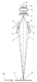
도 1은 이미 도장된 항공기 표면 위에 추후 레이저를 이용하여 리블렛들이 제조되는 것을 도시한 개략도이다.
도 2는 표면 위에 간섭 구조물을 생성하기 위한 빔 분할- 및 집속 장치를 도시한 개략도이다.
도 3은 물질층에서 간섭 구조물이 결상된 것을 도시한 개략도이다.
도 4는 커버 도장층 및 그 아래에 위치한 베이스 도장층에 간섭 구조물이 결상된 것을 도시한 개략도이다.
도 5는 물질층 내에 레이저 방사를 위치적으로 오프셋하여 도입함으로써 리블렛들이 제조되는 것을 도시한 개략도이다.
도 6은 커버 도장층 및 베이스 도장층을 갖는 표면에 레이저 방사를 위치적으로 오프셋하여 도입함으로써 리블렛들이 제조되는 것을 도시한 개략도이다.
도 7은 표면 위로 부분 빔들을 편향시키기 위한 2 개의 틸팅 가능 편향 거울을 포함하는 광학적 구성을 도시한 개략도이다.
도 8은 표면 위로 부분 빔들을 편향시키기 위한 4 개의 틸팅 가능 편향 거울을 포함하는 광학적 구성을 도시한 개략도이다.
도 9는 2 개의 틸팅 가능 편향 거울 및 광학적 편향 몸체를 포함하는 광학적 구성을 도시한 개략적 전면도이다.
도 10은 장형의 레이저 스폿을 도시한 평면도이다.
도 11은 2 개의 틸팅 가능 편향 거울 및 광학적 편향 몸체를 포함하는 광학적 구성을 도시한 개략적 입체 측면도이다.1 is a schematic view showing that the riblets are subsequently manufactured using a laser on an already painted aircraft surface.
2 is a schematic diagram showing a beam splitting- and focusing device for generating an interference structure on a surface.
3 is a schematic diagram showing that an interference structure is formed in a material layer.
4 is a schematic diagram showing that an interference structure is formed on a cover coating layer and a base coating layer located under the cover layer.
FIG. 5 is a schematic diagram showing that riblets are manufactured by introducing a laser radiation into a material layer with a positional offset.
FIG. 6 is a schematic view showing that riblets are manufactured by introducing laser radiation at a position offset to a surface having a cover coating layer and a base coating layer.
FIG. 7 is a schematic diagram showing an optical configuration including two tiltable deflection mirrors for deflecting partial beams over a surface.
8 is a schematic diagram showing an optical configuration including four tiltable deflecting mirrors for deflecting partial beams over a surface.
9 is a schematic front view showing an optical configuration including two tiltable deflection mirrors and an optical deflection body.
10 is a plan view showing a long laser spot.
11 is a schematic three-dimensional side view showing an optical configuration including two tiltable deflecting mirrors and an optical deflecting body.
이하에서는 도면들에서 개략적으로 도시된 실시예들을 참조로 본 발명이 더 상세히 설명되고, 도면들과 관련하여 실시 형태들 및 추가적인 유리한 형성예들이 더 상세히 기술된다.Hereinafter, the present invention will be described in more detail with reference to the embodiments schematically illustrated in the drawings, and embodiments and additional advantageous forming examples will be described in more detail with reference to the drawings.
도 1은 예컨대 신규 도장 또는 재도장 이후 또는 유지관리 시, 항공기(10)의 이미 도장된 표면(3)에 리블렛들(1)을 제조하기 위한 예시적 장치를 도시하고, 리블렛들(1)은 연속파 레이저(2), 특히 CO2 레이저를 이용하여 제조된다. 즉, 표면(3)은 레이저 가공의 시작 시 이미 건조 및 경화되어 있다. 예컨대 연마와 같은 추가적 물질 제거 수단이 사용되지 않는다.FIG. 1 shows an exemplary apparatus for manufacturing the
이동 유닛은 5축 로봇(14)의 방식으로 제공되고, 5축 로봇은 레이저빔(15), 간섭 레이저 방사(16), 추가 레이저빔(17) 및/또는 추가 간섭 레이저 방사(18)가 표면(3)에 대해 상대적으로 이동될 수 있고, 바람직하게는 구동부에 의해 모터 작동식으로 및/또는 구동부를 위한 제어부를 이용하여 자동으로 이동될 수 있도록 구성된다. 따라서 매우 큰 면적율을 갖는 대면적 레이저 구조화 또는 DLIP가 구현될 수 있다. 이동 유닛(14)은 집속 장치(20) 및/또는 빔 분할 장치(21)를 바람직하게는 콤팩트형 부품 유닛으로서 포함하여, 표면(3) 위에서 소정의 스폿 직경이 설정될 수 있고, 이러한 스폿 직경은 특히 상대 이동 중에도 일정하게 유지된다. 연속파 레이저(2)는 이동식 빔 가이드 장치를 통해 집속 장치(20) 및/또는 빔 분할 장치(21)와 연결되어, 이동 유닛(14)이 고정적 연속파 레이저(2)와 무관하게 이동할 수 있다. 가공은 도 1에 도시된 바와 같이 피드 방향(9)으로 수행된다.The mobile unit is provided in the manner of a 5-
일반적으로, 항공기 도장은 다층 시스템이다. 실질적으로, 그러한 항공기 도장용 다층 시스템은 부식 방지 및 부착 증진제로서 프라이머, 특히 컬러 염료를 포함한 베이스 도장층(5)의 베이스 도장 및/또는 커버 도장층(4)의 투명 도장으로 구성된다. 베이스 도장은 일반적으로 다성분 에폭시 수지 코팅이다. 반면 투명 도장은 바람직하게는 폴리우레탄계(PUR)에 기반한다. 항공기 표면의 외관을 손상시키지 않기 위해서는, 리블렛 구조물이 특히 투명한 커버 도장층(4) 내에 도입되는 것이 유리하다. 커버 도장층이 폴리우레탄계로 형성되면, 커버 도장층은 CO2 레이저의 방출 영역 내에서 IR 흡수 구조물을 포함한다. 특히, 특징적 PUR 흡수 대역은 CO2 레이저의 매우 강한 방출 파장(λ = 9.6 ㎛)과 중첩된다. 리블렛 구조물, 즉 리블렛들(1)이 100 ㎛의 고랑부 간격(a)으로 제조되어야 하면, 파장(λ)이 9.6 ㎛일 때 두 부분 빔(6, 7) 사이의 각도(θ)에 대하여 식 2θ = 5°30′이 적용된다.Generally, aircraft painting is a multi-layer system. In practice, such a multi-layer system for aircraft coating consists of a base coating of a
도 2는 레이저빔(15)을 간섭 레이저 방사(16)로 변환하기 위한 빔 분할 장치(21) 및 집속 장치(20)의 예시적 광학적 구성을 도시한다. 다음의 실시 형태는 추가 간섭 레이저 방사(18)로 변환되는 추가 레이저빔(17)에 대해서도 유사하게 적용된다.2 shows an exemplary optical configuration of a
도 2에 도시된 바와 같이, 입사되는 레이저빔(15)은 바람직하게는 비편광 빔 스플리터에서, 바람직하게는 부분 투과성의 거울(22)에서 제1 부분 빔(6) 및 제2 부분 빔(7)으로 분할된다.As shown in FIG. 2, the
이와 유사하게, 대안적 또는 보완적 형성예에서, 입사되는 레이저 빔(15)은, 각각 하나의 세기 최대값(Imax)만을 갖는 2개의 서로 다른 레이저빔이 표면(3)에 고랑부(13)를 형성시키도록 분할될 수 있다.Similarly, in an alternative or complementary forming example, the
도 2의 예시적 광학적 구성에서, 부분 빔들(6, 7)은 광학 거울들(23)을 이용하여 표면(3)으로 조향되어, 이러한 부분 빔들이 소정의 각도(α) 하에 표면에 접촉한다. 거리(L)는 기본적으로 레이저광의 파장(λ) 및 두 부분 빔들(6, 7) 사이의 병합각(2α)에 따라 좌우되고, 특히 식(L = λ/2sinα)에 따른다. 바람직하게는, 식 θ = 2α이 적용되고, 특히 두 빔(6, 7)은 동일한 각도(α) 하에 표면(3)으로 도달한다.In the exemplary optical configuration of FIG. 2, the
특히, 빔 분할 장치(21) 및/또는 집속 장치(20)를 포함하는 전체 광학적 구조물은 콤팩트한 모놀리식 블록으로 형성된다. 이러한 모놀리식 블록은 항공기(10) 또는 항공기 부품의 표면(3)을 따라 매우 간단하게 안내될 수 있다. 이때, 제거 공정은 - 롤러부를 제외하고 - 비접촉식으로 마모 없이 수행되는 것이 유리하다. 일 개발예에서, 이동 유닛은 비접촉식으로 표면 위에서 이동한다. 이로써, 롤러부에 의한 표면 접촉 자체는 방지된다. 간섭 방사를 적용함으로써, 작업 거리, 즉 표면(3)에 대해 상대적인 초점 위치와 관련하여 매우 큰 공차 범위가 가능해질 수 있다.In particular, the entire optical structure including the
바람직하게는, 표면(3)에 대해 수직인 영역 위에서 작업 거리는, 부분 빔들(6, 7)이 표면(3) 위에서 계획에 부합하는 제거를 위해 충분한 정도로 중첩되는, 즉 예컨대 세기 최대값(Imax)이 원하는 임계 세기에 여전히 도달되는 공차 범위 내에 있다. 따라서 자유형 표면도, 일반적으로 집속 장치에 의한 초점 위치를 표면의 높이차에 맞게 조정하기 위해 결정되는 극히 복잡한 경로 제어 없이 가공될 수 있다.Preferably, the working distance over the area perpendicular to the
레이저를 이용하여 원하는 리블렛 구조물 또는 리블렛들(1)을 제조하기 위해, 여러 접근법이 선택될 수 있고, 이러한 접근법들은 이하에서 대안적 또는 보완적 실시 형태들을 참조하여 설명된다. 일 실시 형태에서 자유롭게 연속적으로 설정 가능한 각도(α)에 의해 세기 최대값들(Imax)의 거리(L)는 표면(3)에서 리블렛의 종 방향(8) 또는 피드 방향(9)에 대해 수직인 횡 축(x) 위에서 레이저 세기(I(x))의 특히 주기적 분포에 상응하여 설정될 수 있다. 일 형성예에서, 특히 주기적 세기 분포는 유사 사인 함수, 사인 방식 또는 사인형일 수 있다.To produce the desired riblet structure or
도 3은 횡 축(x)의 위치에서 세기(I(x))가 어떻게 제거 깊이와 상관관계를 가질 수 있고 이로 인하여 이러한 세기 분포가 표면(3)의 높이 프로파일로 전용될 수 있는지를 도시한다.FIG. 3 shows how the intensity I (x) at the position of the transverse axis x can correlate with the removal depth, whereby this intensity distribution can be diverted to the height profile of the
일 형성예에서, 특히 PUR계의 투명 도장으로 구성된 커버 도장층(4)의 두께는 리블렛들(1)의 원하는 고랑부 깊이(d), 즉 리브들(12)의 높이와 같거나 더 크다.In one forming example, the thickness of the
도 4는 물질층 또는 커버 도장층(4)의 아래에 하부층 또는 베이스 도장층(5)이 배치되는 표면(3)을 도시하고, 세기 최대값(Imax)에서의 레이저 방사의 세기(I(x))는 물질층 또는 커버 도장층(4)이 일부 완전히 제거되고, 이로 인하여 하부층 또는 베이스 도장층(5)도 일부 완전히 노출되는 정도이다. 본원에서 일부라는 것은 레이저의 에너지가 세기 최대값(Imax)으로 도입되는 표면(3)의 위치를 의미한다.FIG. 4 shows the
도 3 및/또는 도 4 에서, 레이저 방사는, 특히, 바람직하게는 레이저빔(15)의 변환에 의해 수득되었던 간섭 레이저 방사(16)이다. 대안적 또는 보완적으로, 또한, 도 3 및 도 4에 도시된 고랑부들이 시간 및/또는 위치적으로 오프셋된 비간섭 레이저빔들에 의해 생성되는 것도 기본적으로 가능하고, 이러한 레이저 빔들이 모여 도시된 세기 분포를 생성한다.3 and / or 4, the laser radiation is, inter alia, the interfering
레이저로부터 방출된 레이저광의 파장은 일 형성예에서 커버 도장층(4)에서는 흡수되나 베이스 도장층(5)에서는 TiO2 염료에서의 강한 분산으로 인하여 거의 침투되지 않도록 선택되므로, 레이저를 이용하여 야기되는 제거 공정은 베이스 도장층(5)에서 스스로 중단된다(도 4 참조).The wavelength of the laser light emitted from the laser is absorbed by the
고랑 깊이(d)는 커버 도장층(4)의 두께에 상응하는 반면, 고랑 간격(a)은 세기 최대값들(Imax)의 거리(L)에 상응한다. 하부층 또는 베이스 도장층(5)에서 스스로 중단되는 제거 공정을 이용하여, 매우 고른 밑바닥, 즉 편평한 고랑부 바닥, 및 리브들(12)의 급경사 측부들(11)을 포함하는 고랑부(13)가 얻어질 수 있다.The furrow depth (d) corresponds to the thickness of the cover coating layer (4), while the furrow spacing (a) corresponds to the distance (L) of the intensity maxima (I max ). Using a self-interrupting removal process in the lower layer or
도 5는 제1 가공 단계에서 레이저 방사(16), 그리고 제2 가공 단계에서 추가적 레이저 방사가 위치적으로 오프셋되어 도입됨으로써 리블렛들(1)이 2단계로 제조되는 것을 개략적으로 도시한다.FIG. 5 schematically shows that the
도 5에서는 도면의 명료함을 위해, 제2 가공 단계를 수행하기 전에 제1 가공 단계에 의한 중간 결과가 도시되었다. 그러나 제1 가공 단계 및 제2 가공 단계는 동시에 수행될 수도 있다. 2단계 가공 공정을 통해, 매우 급경사인 측부들(11) 및 첨예한 리브들(12)을 포함하는 리블렛들이 제조될 수 있다.In FIG. 5, for clarity of the drawing, the intermediate result by the first processing step is shown before performing the second processing step. However, the first processing step and the second processing step may be performed simultaneously. Through a two-step processing process, riblets can be produced comprising very
고랑부 폭, 고랑부 깊이, 고랑부 간격 및/또는 고랑부 깊이 대 고랑부 간격의 비율은 바람직하게는 부품의 표면(3)에서 에너지를 흡수하는 난류의 크기에 맞게 조정될 수 있고, 이러한 난류는 통상적인 유동 속도에서 부품의 구동 시 매끄러운 표면에 형성될 것이다. 이상적으로는 예컨대 장거리용 항공기에서 고랑부들(13) 사이에는 2 ㎛ 폭을 가지며 바람직하게는 직사각형 또는 직사각형 방식의 리브들(12)이 구비되어야 한다.The furrow width, furrow depth, furrow spacing and / or ratio of furrow depth to furrow spacing can preferably be adjusted to the size of the turbulence absorbing energy at the
그러나 이러한 리블렛 구조물은 현재 거의 경제적으로 제조될 수 없고, 기계적 안정성은 실무 적용 시 대부분 충분하지 않을 것이다. 따라서 리블렛에서는 이상적 구조물과 유사한 접근법을 사용하여 공기 역학과 기계적 안정성 사이에서 절충안을 얻는 것이 바람직하다. 기본적으로, 에너지를 흡수하는 난류는 유동 속도, 유동 매질의 점도 및 밀도에 따라 좌우된다.However, these riblet structures can hardly be produced economically at present, and mechanical stability will not be sufficient for most practical applications. Therefore, it is desirable to achieve a compromise between aerodynamics and mechanical stability using a similar approach to ideal structures in riblets. Basically, the turbulence that absorbs energy depends on the flow rate, the viscosity and density of the flow medium.
100 ㎛, 바람직하게는 약 100 ㎛의 고랑부 간격, 및/또는 거의 50 ㎛의 고랑부 깊이를 갖는 리블렛들(1)을 포함하는 표면(3)을 구비한 부품에 의해, 장거리용 항공기에서 어느 정도 일정한 비행 속도의 단계에서 전체 유동 저항은 최대 3% 만큼 줄어들 수 있으며, 이러한 전체 유동 저항은 표면 마찰에 의해서만 야기되는 것은 아니다. 이에 상응하여 또한 연료 소모도 감소할 수 있다.In a long-distance aircraft, by a component having a
풍력 발전 설비(WKA)에서, 이상적인 비마찰 유동 시 풍력 에너지의 60%까지 로터의 기계적 에너지로 변환될 수 있다. 이러한 제한은, 로터의 동압이 차단되지 않도록 로터 후방에서는 풍속이 감소하나, 공기는 더 배출되어야 하는 조건으로 인한 것이다.In a wind power plant (WKA), up to 60% of the wind energy in an ideal non-friction flow can be converted into the mechanical energy of the rotor. This limitation is due to the condition that the wind speed decreases at the rear of the rotor so that the dynamic pressure of the rotor is not blocked, but the air must be discharged more.
WKA에서, 로터 블레이드에서 난류 형성 및 벽면 마찰과 같은 공기 역학적 손실은 실제로 사용 가능한 기계적 에너지를 약 50%로 줄인다. 로터 끝단의 원주 속도는 항공기 속도의 약 1/3에 불과하나, 지상에서 공기 밀도는 10,000 m 고도에서보다 3배 크다. 레이놀즈 수는 리블렛(1)의 바람직한 크기에 영향을 미치고, 레이놀즈 수는 밀도와 속도의 곱을 포함하므로, 리블렛의 크기는 기본적으로 100 ㎛ - 200 ㎛의 범위에 있게 된다. 정확한 크기는 특히 WKA의 계획된 회전수에 따라 좌우되고, 로터 블레이드에서 회전축과의 거리에 따라 변경된다. 이를 통해, 벽면 마찰은 최대 10% 만큼 감소할 수 있어서, WKA의 효율은 1% 내지 2% 만큼 개선될 수 있다.In WKA, aerodynamic losses, such as turbulence formation and wall friction in the rotor blades, actually reduce the usable mechanical energy to about 50%. The circumferential speed at the rotor end is only about one third of the speed of the aircraft, but the air density on the ground is three times greater than at an altitude of 10,000 m. The Reynolds number affects the preferred size of the
일 실시 형태에서, 리블렛들(1)은 특히 두 부분 빔들(6, 7)의 중첩 각도(α)의 지속적 또는 단계적 증가 또는 감소에 의해 제조됨으로써, 리블렛들은 특히 종축(8)에 대해 횡 방향으로 작아지거나 커지는 고랑부 폭(L)을 가진다. 로터 블레이드(미도시) 위에서의 리블렛들(1)은 허브와의 거리가 멀어지면서 증가하는 원주 속도에 맞게 매우 간단하고 효과적으로 조정될 수 있다.In one embodiment, the
다른 형성예에서, 무역용 선박에서 선저 표면은 리블렛들(1)을 구비할 수 있다. 10 내지 20 노트라는 이러한 선박의 통상적 항해 속도에 따라, 80 ㎛와 200 ㎛ 사이의 고랑부 폭을 갖는 리블렛들이 형성된다. 그러한 리블렛들(1)은 DLIP를 이용하여 선저 도장물에 도입될 수 있다.In another forming example, the bottom surface of the ship for trade may be provided with
언급한 실시 형태들 및 예시적 적용예들은, 방법, 장치 및 이를 통해 제조될 수 있는 부품 또는 표면이 광범위하게 사용될 수 있음을 시사한다.The above-mentioned embodiments and exemplary applications suggest that the method, apparatus, and parts or surfaces that can be produced therefrom can be widely used.
이때 매우 유리하게는,At this time, very advantageously,
- 리블렛들(1)의 크기는 부분 빔들(6, 7)에서 각도(α)의 단순 변경에 의해 변경될 수 있고,-The size of the
- 리블렛들(1)의 고랑부 깊이(d)는 세기 및 피드 속도에 의해 설정될 수 있고,-The depth (d) of the furrow of the
- 매우 급경사의 측부들(11), 슬림하고 첨예한 리브들(12)을 포함하는 리블렛들(1)이 생성될 수 있고, 특히 실질적으로 동일한 간섭 구조물들, 바람직하게는 오프셋된 광학계 헤드들에 의해 생성되는 간섭 구조물들이 약간 오프셋되어 중첩됨으로써 매우 간단하게 생성될 수 있고,-
- 가공은 특히 비접촉식으로 및/또는 마모 없이 이루어지고, 즉 긴 유효 수명을 얻을 수 있고,-Processing is particularly non-contact and / or without wear, i.e. long lifespan can be obtained,
- 기본적으로 정량적으로 감지될 수 있는 분진 및/또는 증기가 매우 적게 발생하고,-Basically, very little dust and / or vapor can be detected quantitatively,
- 가공은 전자동으로 및/또는 원격 제어 방식으로 수행될 수 있고,-Machining can be carried out automatically and / or remotely,
- CO2 연속파 레이저를 사용함으로써 확장성(scalability)은 분당 수 평방미터의 면적 출력에 이르기까지 가능하고, 및/또는-By using a CO 2 continuous wave laser, scalability is possible up to an area output of several square meters per minute, and / or
- 일반적으로, 9.6 ㎛의 파장에서 CO2 연속파 레이저의 구동 시 특히 내구성 및 내후성을 갖춘 폴리우레탄 도장이 매우 신속하고 높은 품질로 가공될 수 있다.-In general, when driving a CO 2 continuous wave laser at a wavelength of 9.6 μm, a polyurethane coating having particularly durability and weather resistance can be processed very quickly and with high quality.
유리한 형성예에서, 리블렛들은 추후 표준에 맞는 경화된 도장물에 도입된다. 이로써 매우 유연한 리블렛 도입이 가능해진다.In an advantageous formation, the riblets are subsequently introduced into a cured coating that meets the standards. This makes it possible to introduce highly flexible riblets.
유리한 형성예에서, 리블렛 구조물들은 간섭 레이저 방사 또는 간섭 패터닝에 의해 생성된다. 이를 통해 리블렛들은 매우 높은 가공 속도로 도입될 수 있다.In an advantageous formation, riblet structures are produced by interfering laser radiation or interfering patterning. This allows riblets to be introduced at very high processing speeds.
유리한 형성예에서, 간섭 레이저 방사 또는 간섭 패터닝의 간섭 구조물들은 특히 약간 이동되어 형성된다. 매우 첨예하고 날카로운 리블렛 끝단부들은 특히 약간 이동된 간섭 구조물들의 중첩에 의해 생성될 수 있다.In an advantageous formation, the interfering structures of the interfering laser radiation or interfering patterning are formed in particular slightly shifted. Very sharp and sharp riblet ends can be created, in particular, by overlapping slightly shifted interference structures.
유리한 형성예에서, CO2 레이저가 사용된다. 통상적인 도장계 및 매우 유리한 리블렛 크기는 매우 정확하고 효과적으로 생성될 수 있다.In an advantageous formation example, a CO 2 laser is used. Conventional paint systems and very advantageous riblet sizes can be produced very accurately and effectively.
유리한 형성예에서, 9.6 ㎛의 파장을 갖는 레이저가 사용된다. 따라서 PUR 도장에서 매우 높은 흡수가 가능해질 수 있다.In an advantageous formation, a laser with a wavelength of 9.6 μm is used. Therefore, very high absorption may be possible in PUR coating.
이미 앞에서 설명한 바와 같이, 부품의 상이한 위치들에서 도입되는 리블렛들(1)이 구동 시 이 위치에서 지배적인 유동 조건들, 즉 유동 속도 및/또는 기압에 맞게 조정되면서, 부품에서 구동 시 유동 저항은 전체적으로 보다 양호하게 감소할 수 있다. 허브와의 거리가 멀어지면서 로터 블레이드에서 유동 속도가 증가하는 풍력 발전 설비에서, 전술한 실시 형태들 중 하나에서와 같이 연속적으로 자유롭게 설정 가능한 각도(α)에 의하여, 세기 최대값들(Imax)의 거리(L)는 표면(3) 위에서 리블렛들의 종 방향(8) 또는 피드 방향(9)에 대해 수직인 횡 축(x) 위에서 레이저 세기(I(x))의 특히 주기적인 분포에 상응하여 설정될 수 있다.As already described above, the flow resistances when driven on a part, while the
유동의 벽면 마찰은 이러한 방식으로 특정한 정도로 종합적으로 감소할 수 있다. 항공기에서 예컨대 연료 소모가 감소할 수 있거나 풍력 발전 설비에서 이러한 설비의 효율이 증가할 수 있다. 따라서, - 예컨대 리블렛의 크기, 거리(L)에 대해 상관 관계를 가지는 고랑부 폭 또는 고랑부 간격(a)과 같이 - 리블렛들(1)의 적어도 하나의 기하학적 매개변수가 부품의 구동 시 국소적 유동 조건에 맞게 조정되는 것은 매우 유리하다.The wall friction of the flow can be collectively reduced to a certain degree in this way. In aircraft, for example, fuel consumption may be reduced, or in wind power plants, the efficiency of such plants may increase. Thus, at least one geometrical parameter of the
그러므로 항공기에서 구동 시 국소적으로 서로 다른 유동 조건들로 인하여, 리블렛들(1)의 하나 이상의 기하학적 매개변수를 항공기를 따르는 통상적인 국소적 유동 흐름, 동체의 상측 및 하측에서 및/또는 날개 또는 꼬리 날개를 따르는 통상적인 국소적 유동 흐름에 맞게 조정하는 것이 유리하다. 풍력 발전 설비 또는 WKA의 구동 시, 기압 및 로터 회전수는 거의 일정하고, 접선 유동 속도는 로터 블레이드를 통해 로터 허브와의 거리에 따라 선형으로 증가한다. 본원에서 리블렛들(1)의 도입 시, 허브로부터 끝단에 이르기까지 생성되는 리블렛들(1)이 예컨대 점점 더 세밀하게 되는 것이 매우 유리하다. 또한, 로터의 전면측 및 후면측을 위한 최적의 리블렛 구조물들은 서로 상이하다.Therefore, due to locally different flow conditions when operating in an aircraft, one or more geometrical parameters of the
따라서, 유동 저항의 감소와 관련하여 리블렛들의 잠재 성능을 보다 양호하게 활용할 수 있기 위해, 유리한 실시 형태에서, 부품을 위해 구동 시 지배적인 국소적 유동 조건에 맞게 조정된 리블렛 구조물을 생성하는 것이 고려된다. 이는 사전 각인된 접착 필름 또는 스탬프를 이용하는 경우에 가능하지 않거나 비경제적 비용을 들여서만 가능한 것이다.Thus, in order to be able to better utilize the potential performance of the riblets in connection with a decrease in flow resistance, in an advantageous embodiment, it is desirable to create a riblet structure adapted to dominant local flow conditions when driven for the part. Is considered. This is not possible in the case of using a pre-stamped adhesive film or stamp, or only at an uneconomical cost.
바람직한 실시 형태에서, 리블렛 제조 중에, 특히 표면(3) 내에 리블렛들(1)의 도입 중에, 2개의 간섭 부분 빔들(6, 7) 간의 병합 각도(θ)는 목적에 맞게 변경되는 것이 고려된다.In a preferred embodiment, it is contemplated that the merging angle θ between the two interfering
병합 각도(θ)는 부분 빔들의 재병합 시 또는 바꾸어 말하면 부분 빔들의 교차 또는 맞닿음 시, 2개의 간섭 부분 빔들(6, 7)에 의해 에워싸이는 각도를 나타낸다. 이하에서는 부분 빔들의 재병합, 교차 또는 맞닿음의 지점을 "교점"으로 명명한다. 이하에서, "가공 거리"는 가공 헤드 또는 고정된 편향 거울(24)의 틸팅 축(27)으로부터 적어도 2개의 부분 빔들의 교점의 거리를 지칭한다.The merging angle θ represents the angle enclosed by the two interfering
특히, 교점은 표면(3) 위에 위치한다. 2개의 간섭 부분 빔들(6, 7) 사이의 병합 각도(θ)는 표면(3)에 접촉할 때 측정될 수 있다. 중앙 축(26) 둘레에서 두 간섭 부분 빔들(6, 7)이 대칭으로 접촉할 때 θ= 2α이고, 이때 α는 중앙 축(26) 및 제1 또는 제2 부분 빔(6, 7)에 의해 에워싸이는 각도이다. 병합 각도(θ)는 간섭 각도일 수 있거나 그러한 간섭 각도로서 지칭될 수 있다.In particular, the intersection point is located on the
병합 각도(θ)를 목적에 맞게 변경한다는 것은, 원하는 병합 각도(θ)를 얻기 위해 계획에 맞게 변경하는 것을 의미한다. 목적에 맞는 변경은 제어부를 이용하여 전자동으로 또는 특히 사용자의 개입을 통해 반자동으로 수행된다. 전술한 바와 같이, 2개의 간섭 부분 빔들(6, 7)은 결맞음 레이저빔(15)이 분할됨으로써 수득되었다. 간섭 부분 빔들(6, 7)은 간섭 레이저 방사(16)를 형성하고 및/또는 이에 상응하여 배분된 에너지를 표면(3)으로 도입시켜, 물질 제거를 통해 리블렛들(1)이 제조된다.Changing the merging angle θ to suit the purpose means changing it according to the plan to obtain the desired merging angle θ. The change according to the purpose is performed automatically using a control unit or semi-automatically, especially through user intervention. As described above, two interfering
병합 각도(θ)를 목적에 맞게 변경함으로써, 목적에 맞게 변경된 이 병합 각도(θ)로 표면(3) 내에 도입되는 리블렛들(1)의 적어도 하나의 기하학적 매개변수가 목적에 맞게 조정될 수 있다. 특히, 병합 각도(θ)를 목적에 맞게 변경함으로써 목적에 맞게 조정될 수 있는 리블렛들(1)의 기하학적 매개변수들에는 특히 고랑부 간격(a), 고랑부 폭 및 고랑부 깊이(d) 대 고랑부 간격(a)의 비율이 속한다.By changing the merging angle θ to suit the purpose, at least one geometrical parameter of the
일 실시 형태에서, 병합 각도(θ)를 목적에 맞게 변경함으로써 리블렛들(1)의 고랑부 간격(a), 고랑부 폭 및/또는 고랑부 깊이(d) 대 고랑부 간격(a)의 비율이 목적에 맞게 변경될 수 있다.In one embodiment, the furrow spacing (a), furrow width and / or furrow depth (d) vs. furrow spacing (a) of the riblets (1) by changing the merging angle (θ) as desired The ratio can be changed to suit the purpose.
일 실시 형태에서, 병합 각도(θ)를 목적에 맞게 변경함으로써 리블렛들(1)의 고랑부 간격(a), 고랑부 폭 및/또는 고랑부 깊이(d) 대 고랑부 간격(a)의 비율은 표면(3)의 가공할 영역에서 구동 시 통상적으로 지배적인 유동 조건들에 따라 적합하게 조정될 수 있다. 가공할 영역은 표면(3)의 국소적으로 제한된 영역을 의미한다. 이미 병합 각도(θ)를 목적에 맞게 변경하는 동안 또는 가공 헤드가 피드 방향(9)으로 이동하거나 가공 헤드의 피드 동작을 계속하면, 이러한 가공할 영역 내에 리블렛들(1)이 도입된다. 유동 조건들을 위해 유동 속도 및/또는 기압이 원용될 수 있다. 구동 시 통상적으로 지배적인 유동 조건들은 측정, 계산 및/또는 추정에 의해 산출될 수 있다. 바람직하게는, 통상적으로 지배적인 유동 조건들을 위해 평균값 또는 가중된 평균값이 사용된다.In one embodiment, the furrow spacing (a), furrow width and / or furrow depth (d) vs. furrow spacing (a) of the riblets (1) by changing the merging angle (θ) as desired The ratio can be suitably adjusted according to the flow conditions that are typically dominant when driven in the area to be machined of the
일 형성예에서 제어부가 구비되고, 이러한 제어부에는 표면(3)의 영역 위치 또는 가공 지점(29)의 위치에 따라 병합 각도(θ)가 저장됨으로써, 표면(3) 위에서 가공 헤드의 이동 시 제어부를 이용하여 자동으로 병합 각도(θ)가 설정되고, 이러한 병합 각도는 현재 가공되는 표면(3)의 영역 또는 현재의 가공 지점(29)을 위해 고려되는 것이다. 특히, 경로 센서가 구비됨으로써, 제어부는 표면(3)에 대해 상대적인 가공 지점(29) 또는 가공 헤드의 현재 위치에 관한 정보를 수득한다. 특히, 병합 각도(θ)의 설정 또는 변경을 위해, 제어부는 틸팅 가능한 편향 거울(24)의 모터 작동식 틸팅을 위한 구동부를 제어할 수 있다.In one forming example, a control unit is provided, and the control angle is stored in the control head when the processing head is moved on the
일 형성예에서, 표면(3)의 가공할 한 영역에 대하여, 이 영역에서 구동 시 예상되는 큰 유동 속도로 인하여 이 영역에서 제조될 리블렛들(1)을 위한 고랑 간격(a)이 계획에 따라 더 짧게 구비되어야 할 때, 병합 각도(θ)는 확대된다.In one forming example, for one area to be machined of the
일 형성예에서, 표면(3)의 가공할 한 영역에 대하여, 이 영역에서 구동 시 예상되는 낮은 유동 속도로 인하여 이 영역에서 제조될 리블렛들(1)을 위한 고랑 간격(a)이 계획에 따라 더 길게 구비되어야 할 때, 병합 각도(θ)는 축소된다.In one forming example, for one area to be machined of the
예컨대 항공기 날개 또는 로터 블레이드와 같은 부품의 각 위치에서 리블렛들(1)이 이러한 매우 효율적이며 경제적인 방식으로 이 위치에서 구동 시 지배적인 유동 조건들에 맞춰질 수 있어서, 저항 감소가 극대화된다.The
일 실시 형태에서, 가공 헤드는, 레이저로부터 가공 헤드로 입사되는 레이저빔(15)이 복수의 부분 빔들(6, 7)로 분할된 후, 간섭 방사(16)를 형성하도록 원하는 간섭 구조물과 함께 다시 결합되도록 구성된다. 유사한 방식으로, 이는 추가적 레이저빔(17)에 대해서도 적용될 수 있다. 리블렛들은 매우 용이하게 취급 가능한 모놀리식 가공 헤드를 이용하여 제조될 수 있다. 레이저빔(15) 또는 추가 레이저빔(17)을 부분 빔들(6, 7)로 분할하기 위해, 빔 분할 장치 또는 빔 스플리터가 사용될 수 있다. 부분 빔들(6, 7)의 결합을 위해, 편향 거울들(23), 틸팅 가능한 편향 거울들(24) 및/또는 광학적 편향 몸체(30)가 사용될 수 있다.In one embodiment, the machining head is again divided with a desired interference structure to form an
일 실시 형태에서, 빔 스플리터는 회절 광학 소자(DOE)이거나 또는 빔 분할 장치가 DOE를 포함한다. 이를 통해 레이저빔(15) 또는 추가 레이저빔(17)은 거의 에너지 손실 없이 2개 이상의 부분 빔들(6, 7)로 분할될 수 있고, 바람직하게는 정확히 2개 또는 정확히 4개의 부분 빔들(6, 7)로 분할될 수 있다. DOE 내에서 간섭 효과로 인하여, 입사되는 레이저빔은 2개, 3개, 4개 또는 그 이상의 부분 빔들(6, 7)로 나눠진다. 2개, 3개, 4개 또는 그 이상의 부분 빔들(6, 7)은 특정한 각도 하에 편향된다. 일 형성예에서, DOE는 투과성 DOE이다. 그러면 부분 빔들(6, 7)은 DOE를 통하여 투과된다. 대안적으로, DOE는 반사성 DOE이다. 그러면 부분 빔들(6, 7)은 DOE를 통해 반사된다.In one embodiment, the beam splitter is a diffractive optical element (DOE) or the beam splitting device comprises a DOE. Through this, the
바람직하게는, DOE는 반사성 또는 투과성의 위상 격자(25)이다. 이를 통해 가공 헤드는 매우 콤팩트한 구성으로 구현될 수 있다. 반사성 위상 격자(25)는 매우 견고하고, 비교적 높은 손상 임계를 포함한다. 투명한 위상 격자(25)는 매우 슬림한 가공 헤드 구성을 가능하게 한다. 위상 격자(25)를 이용하여 단색 레이저빔(15)은 서로 다른 부분 빔들(6, 7)로 분할될 수 있고, 이때 격자 상수는 위상 격자(25) 바로 뒤에서 부분 빔들(6, 7)의 편향 각도를 결정하는 반면, 부분 빔들의(6, 7)의 세기는 적절하게 설정된 레이저의 출력에 의해 리블렛의 개수 및 기하학적 형상에 맞춰질 수 있다. 반사성 또는 투명한 위상 격자는 일 형성예에서, 특히 격자 매개변수의 적절한 선택에 의해, 입사되는 레이저빔(15)이 2개, 3개, 4개 또는 그 이상의 동일한 부분 빔들(6, 7)로 분할될 수 있도록 구성될 수 있다. 특히, 동일한 부분 빔들(6, 7)은 레이저빔(15)의 초기 빔 방향에 대해 대칭으로 편향된다. 바람직하게는, 레이저빔(15)이 반사성 또는 투명한 위상 격자로 입사되는, 레이저빔(15)의 초기 빔 방향은 중앙 축(26)을 따라 진행한다. 이와 유사한 방식으로, 일 실시 형태에서, 반사성 또는 투명한 위상 격자는 추가 레이저빔(17)을 위해 사용된다.Preferably, the DOE is a reflective or transmissive phase grating 25. Through this, the processing head can be realized in a very compact configuration. The reflective phase grating 25 is very robust and includes a relatively high damage threshold. The transparent phase grating 25 enables very slim processing head construction. Using the phase grating 25, the
대안적 또는 보완적 실시 형태에서, 빔 스플리터는 부분 반사성 거울이거나 또는 빔 분할 장치가 부분 반사성 거울을 포함한다. 그러면 입사되는 레이저빔(15)이 일부는 투과되고, 일부는 반사된다.In alternative or complementary embodiments, the beam splitter is a partially reflective mirror or the beam splitting device comprises a partially reflective mirror. Then, the
일 실시 형태에서, 병합 각도(θ)를 목적에 맞게 변경하기 위해, 부분 빔(6, 7)의 편향을 위한 적어도 하나의 틸팅 가능한 편향 거울(24)이 틸팅된다. 따라서 병합 각도(θ)는 매우 간단하고 신뢰할만한 방식으로 목적에 맞게 변경될 수 있다.In one embodiment, at least one
일 실시 형태에서, 병합 각도(θ)를 목적에 맞게 변경하기 위해, 부분 빔(6, 7)의 편향을 위한 2개 또는 4개의 틸팅 가능 편향 거울(24)이 틸팅된다. 특히, 정확히 하나의 부분 빔(6, 7)을 위해 각각 하나의 틸팅 가능 편향 거울(24)만이 구비된다. 대안적 또는 보완적으로, 틸팅 가능 편향 거울(24)은, 2개의 부분 빔들(6, 7)이 계획에 맞게 편향될 수 있도록 형성되거나 구성될 수 있다. 대안적 또는 보완적 실시 형태에서, 모든 틸팅 가능 편향 거울(24)은 동시적으로만 틸팅 가능하다. 특히, 동시적으로만 틸팅 가능한 2개 또는 4개의 편향 거울(24)은 병합 각도(θ)의 목적에 맞는 변경을 위해 제공된다. 틸팅 시, 편향 거울(24)의 틸팅 각도는 틸팅 각도 변경(δ) 만큼 변경된다.In one embodiment, two or four tiltable deflection mirrors 24 for the deflection of the
2개의 인접한 세기 최대값들(Imax) 사이에서 리블렛들(1)의 주기적 거리(L)는 부분 빔들(6, 7)의 병합 각도(θ)에 의해 결정된다. 틸팅 가능한 편향 거울(24)의 틸팅 각도가 틸팅 각도 변경(δ) 만큼 특히 동시에 변경됨으로써, 각도(θ) 및 이로 인하여 거리(L)는 목적에 맞게 변경될 수 있다. 특히, 편향 거울(24)은 틸팅 축(27) 둘레에서 틸팅된다. 바람직하게는, 틸팅 축(27)은 중앙 축(26)에 대해 수직으로 배향된다.The periodic distance L of the
바람직하게는, 2개 또는 4개의 틸팅 가능 편향 거울(24)은 중앙 축(26) 둘레에서 대칭으로 배치된다. 대칭으로 배치되는 2개의 틸팅 가능한 편향 거울(24)로 각각 구성되는 1개의 거울쌍 또는 2개의 거울쌍이 수득된다. 동시적으로만 틸팅 가능하다는 것은, 동시적으로만 틸팅 가능한 편향 거울들(24)의 틸팅 동작이 상호 고정 비율을 가지거나 동일한 틸팅 각도 변경을 포함하는 것을 의미한다. 기하학적 형상이 변경된 리블렛들을 도입하기 위해, 동시에 틸팅 가능한 편향 거울(24)이 이에 상응하여 동시에 틸팅되고, 바람직하게는 모든 2개 또는 4개의 틸팅 가능한 편향 거울(24)이 틸팅 각도 변경(δ)의 동일한 값만큼 동시에 틸팅된다. 병합 각도(θ)를 목적에 맞게 변경하기 위해, 정확히 2개의 틸팅 가능한 편향 거울(24)이 구비되면, 2개의 틸팅 가능한 편향 거울(24)은 바람직하게는 동일한 틸팅 각도만큼 틸팅된다. 병합 각도(θ)를 목적에 맞게 변경하기 위해, 정확히 2개의 거울쌍이 구비되면, 각 거울 쌍의 2개의 틸팅 가능한 편향 거울(24)은 바람직하게는 항상 동일한 틸팅 각도만큼 틸팅된다. 기본적으로, 한 거울 쌍의 틸팅 가능한 편향 거울들(24)의 틸팅은 중앙축(26)에 대해 거울 대칭으로 수행된다.Preferably, two or four tiltable deflection mirrors 24 are arranged symmetrically around the
일 실시 형태에서, 2개의 틸팅 가능한 편향 거울(24)은 짐벌(gimbal) 방식의 틸팅 가능한 편향 거울(24)이다. 짐벌 방식의 틸팅 가능한 편향 거울은 입사되는 빔, 예컨대 레이저빔 또는 부분 빔이 거울 표면과 만나는 접촉 지점 둘레에서 틸팅될 수 있으므로, 빔의 회전점은 항상 동일하게 유지될 수 있다.In one embodiment, the two tiltable deflection mirrors 24 are gimbal tiltable deflection mirrors 24. The gimbal tiltable deflecting mirror can be tilted around the point of contact where the incident beam, for example a laser beam or a partial beam, meets the mirror surface, so that the rotational point of the beam can always remain the same.
일 실시 형태에서, 2개의 틸팅 가능한 편향 거울(24)의 모터 작동식 틸팅을 위해 구동부가 구비되는데, 특히 서로 다르게 배향된 하나 이상의 틸팅 축에서의 틸팅을 위해 구동부가 구비된다. 따라서 높은 자동화도가 달성될 수 있다.In one embodiment, a drive is provided for motor-driven tilting of the two tiltable deflecting mirrors 24, especially for tilting in one or more differently oriented tilting axes. Therefore, a high degree of automation can be achieved.
일 형성예에서, 적어도 2개의 부분 빔(6, 7), 특히 정확히 2개 또는 정확히 4개의 부분 빔(6, 7)은 각각 하나의 틸팅 가능한 편향 거울(24)에 의해 직접적으로 리블렛(1)의 도입을 위한 표면(3)으로 또는 광학적 편향 몸체(30)로 조향될 수 있다. 따라서 매우 간단한 구성의 가공 헤드가 구현될 수 있다.In one embodiment, at least two
일 실시 형태에서, 이러한 적어도 하나의 틸팅 가능한 편향 거울(24)은 표면(3)으로 부분 빔(6, 7)을 지향시킨다. 특히, 이러한 부분 빔(6, 7)이 직접적으로 틸팅 가능한 편향 거울(24)에 의해 표면으로 지향되고, 즉 편향된다. 따라서 매우 간단한 구성의 가공 헤드가 구현될 수 있다.In one embodiment, this at least one
일 형성예에서, 가공 헤드 또는 광학 부재들의 배치는, 틸팅 가능한 편향 거울(24)의 틸팅에 의해 가공 거리가 변경되도록 구성된다. 병합 각도(θ) 하에서 맞닿는 2개의 간섭 부분 빔들(6, 7)의 교점으로부터 고정식 편향 거울(24)의 틸팅 축(27) 또는 가공 헤드의 거리는 틸팅 가능한 편향 거울(24)의 틸팅 시 변경된다.In one embodiment, the placement of the processing head or optical members is configured such that the processing distance is changed by tilting the
특히, 병합 각도(θ)를 목적에 맞게 변경함에 따르는 가공 거리의 변경을 보상하기 위해, 가공 헤드의 추적이 고려된다. 따라서, 부분 빔들(6, 7)의 교점이 대략적으로 표면(3)의 높이에 및/또는 원하는 가공 지점(29)에 있는 것이 보장된다. 바람직하게는, 집속 장치는, 부분 빔들(6, 7)의 초점 위치가 대략적으로 표면(3)의 높이에 및/또는 원하는 가공 지점(29)에 있도록 설정 및/또는 추적된다. 초점 위치는 빔 확산 방향과 관련하여 가공할 표면(3) 위의 가공 지점(29)에 대해 빔 경로 내에서 가장 좁은 스폿 직경의 위치를 나타낸다. 가공 거리 및/또는 초점 위치의 변경을 통해 가공할 표면(3) 위에서 스폿 직경 또는 레이저 스폿(36)(도 10 참조)이 영향받는다. 이를 통해 다시 가공 지점(29)에 작용하는 간섭 레이저 방사(16)의 세기가 변경되고, 이는 기본적으로 예컨대 고랑부 깊이(d) 또는 갭 폭에 영향을 미칠 수 있다.In particular, tracking of the machining head is considered to compensate for the change in the machining distance resulting from changing the merging angle θ to suit the purpose. It is thus ensured that the intersection of the
틸팅 가능한 편향 거울들(24)의 틸팅에 의해 가공 거리가 변경되는 대안적 형성예에서, 이러한 방식으로 변경되는 가공 거리로 인하여 고랑부 깊이(d) 및/또는 리블렛(1)의 갭 폭을 목적에 맞게 변경하기 위해, 가공 헤드의 추적은 고려되지 않는다.In an alternative formation in which the working distance is changed by tilting the tiltable deflecting mirrors 24, the gap width of the furrow depth d and / or the
일 실시 형태에서, 틸팅 가능한 편향 거울들(24)은 표면(3)으로의 편향을 위한 광학적 편향 몸체(30) 쪽으로 부분 빔(6, 7)을 각각 지향시킨다. 틸팅 가능한 편향 거울들(24)과 가공할 표면(3) 사이의 빔 경로 내에서 광학 편향 몸체(30)를 사용함으로써, 매우 콤팩트한 구성의 가공 헤드가 얻어지고, 광학 소자들의 개수도 감소할 수 있다. 특히, 광학적 편향 몸체(30)에 의해, 병합 각도(θ)의 목적에 맞는 변경 중에 가공 거리가 특히 틸팅 가능한 편향 거울(24)의 틸팅에 의해 동일하게 유지되도록 할 수 있다.In one embodiment, the tiltable deflection mirrors 24 direct the
일 실시 형태에서, 광학 편향 몸체(30)는 부분 빔(6, 7)의 편향을 위해 2차원으로 만곡되거나 3차원으로 만곡된 편향면(31)을 포함한다. 일 형성예에서, 2차원 또는 3차원으로 만곡된 표면은 타원형으로 만곡된다. 따라서, 병합 각도(θ)의 목적에 맞는 변경 중에 가공 거리가 특히 틸팅 가능한 편향 거울(24)의 틸팅에 의해 동일하게 유지되는 것이 달성될 수 있다.In one embodiment, the
일 형성예에서, 광학 편향 몸체(30) 및/또는 편향면(31)은 부분 빔(6, 7)에 대해 반사성이고, 즉 투명하지 않다. 바람직하게는, 광학 편향 몸체(30) 및/또는 편향면(30)은 금속으로, 바람직하게는 구리로 구성된다.In one forming example, the optical deflecting
일 실시 형태에서, 부분 빔(6, 7)의 편향을 위한 광학 편향 몸체(30)는 틸팅 가능한 편향 거울(24)의 틸팅 각도 변경(δ)에 따라 병합 각도(θ)를 목적에 맞게 변경시키기 위해 2차원으로 만곡된 편향면(31)을 포함한다. 특히, 가공 거리는 틸팅 각도 변경(δ)과 무관하다.In one embodiment, the
이와 같이 2차원으로 만곡된 편향면(31)이 구비됨으로써, 병합 각도(θ)를 목적에 맞게 변경시키기 위해 틸팅 각도 변경(δ) 만큼 틸팅 가능한 편향 거울(24)이 틸팅되는 중에도 동일하게 유지되는 가공 거리가 수득될 수 있다. 따라서 가공 헤드의 추적은 생략될 수 있다. 가공 헤드가 예컨대 롤러부를 이용하여 표면(3)에 대해 일정한 거리로 피드 방향으로 이동하면, 병합 각도(θ)는 거리 조정 없이 목적에 맞게 연속적이고 신속하며 신뢰할만하게 변경될 수 있다.By providing the
일 형성예에서, 2차원으로 만곡된 편향면(31)은 틸팅 가능한 편향 거울들(24)의 틸팅 평면에서 연장되고, 즉 틸팅 축(27)에 대해 수직으로 연장된다.In one embodiment, the two-dimensionally
일 형성예에서, 2차원으로 만곡된 편향면(31)은 타원형 윤곽부를 포함하고, 타원형 윤곽부는 타원체(32)의 일 부분에 상응한다. 일 형성예에서, 이러한 타원체(32)는 틸팅 가능한 편향 거울(24)의 틸팅 축(27)에서 제1 초점을 가진다. 일 형성예에서, 이러한 타원체(32)는 부분 빔들의 교점 및/또는 가공할 표면(3) 위의 가공 지점(29)에서 제2 초점을 가진다. 병합 각도(θ)가 변경될 시, 매우 신뢰할만하게 동일하게 유지되는 가공 거리가 가능해진다.In one forming example, the two-dimensionally
바람직하게는, 빔 스플리터 또는 빔 분할 장치 앞의 빔 경로 내에 집속을 위한 렌즈(33)가 구비됨으로써, 광학 편향 몸체(30)를 통해서는 집속 없이 오로지 편향만이 수행된다.Preferably, the
일 실시 형태에서, 부분 빔(6, 7)의 편향을 위한 광학 편향 몸체(30)는 표면(3)으로 부분 빔(6, 7)을 집속시키기 위해 및/또는 틸팅 가능한 편향 거울(24)의 틸팅 각도 변경(δ)에 따라 병합 각도(θ)를 목적에 맞게 변경시키기 위해 3차원으로 만곡된 편향면(31)을 포함한다. 특히, 가공 거리는 틸팅 각도 변경(δ)과 무관하다. 특히, 3차원으로 만곡된 편향면(31)은 타원체형, 바람직하게는 포물선형 또는 구형의 만곡부를 포함한다.In one embodiment, the optical deflecting
일 형성예에서, 3차원으로 만곡된 편향면(31)은 서로 중첩되는 2개의 2차원 만곡부에 상응하고, 이때 2개의 2차원 만곡부의 평면들은 서로 수직으로 배향된다.In one forming example, the three-dimensionally
특히, 첫 번째 2차원 만곡부는 틸팅 축(27)에 대해 수직인 평면에서 연장되고 및/또는 틸팅 가능한 편향 거울(24)의 틸팅 각도 변경(δ)에 따라 병합 각도(θ)를 목적에 맞게 변경시키기 위한 전술한 2차원 만곡부들에 상응한다. 바람직하게는, 첫 번째 2차원 만곡부는 타원체(32)의 전술한 제1 초점 및/또는 제2 초점을 포함한다.In particular, the first two-dimensional curved portion extends in a plane perpendicular to the tilting
특히, 두 번째 2차원 만곡부는 중앙 축(26)에 대해 수직인 평면에서 연장되고 및/또는 다른 부분 빔과의 교점에서 및/또는 가공할 표면(3) 위의 가공 지점(29)에 입사되는 부분 빔을 집속하기 위해 바람직하게는 포물선형 또는 원형 세그먼트 형상의 윤곽부를 포함한다.In particular, the second two-dimensional curve extends in a plane perpendicular to the
일 형성예에서, 3차원으로 만곡된 편향면(31)은 틸팅 가능한 편향 거울(24)의 틸팅 축(27)에 대해 수직인 제1 평면에서 타원체 형상의 만곡부 및 이에 대해 수직으로 포물선형 또는 구형 만곡부를 포함한다. 특정하게 이 경우에서 "~에 대해 수직"이란 표현은, 제1 평면에 대해 수직이며 각 지점에서 표면 법선을 따르는 것을 의미한다. 3차원으로 만곡된 편향면(31)의 포물선형 또는 구형의 만곡부는 표면(3)으로 부분 빔(6, 7)으로 집속시키는 역할을 한다. 타원체형 만곡부는 특히 전술한 첫 번째 2차원 만곡부에 상응한다.In one forming example, the three-dimensionally
포물선형 만곡부는, 이러한 만곡부가 단일 축 둘레에서 부분 빔(6, 7)을 집속시킬 수 있다는 이점이 있다. 가공 헤드에 의해 포괄되며 빔 경로 내에서 광학적 편향 몸체(30) 앞에 배치되는, 레이저 빔(15)의 집속을 위한 집속 렌즈(33) 또는 예비 집속은 생략되고, 광학 소자들의 개수도 감소할 수 있다. 또한, 표면에 대해 더 근접함으로써 보다 양호하게 집속될 수 있다. 구 형상의 만곡부는 특히 정확한 집속이 매우 간단하고 신뢰할만하게 수행될 수 있다는 이점이 있다.The parabolic curve has the advantage that the curve can focus the
이를 통해, 틸팅 가능한 편향 거울(24)에 의해 편향면(31)으로 지향되는 부분 빔(6, 7)은 목적에 맞게 설정 및 변경이 가능한 병합 각도(θ)로 표면(3)에 집속될 수 있고, 이때 병합 각도(θ)는 틸팅 가능한 편향 거울(24)의 틸팅 각도에 따라 좌우된다.Through this, the
특히, 3차원으로 만곡된 편향면(31)을 포함하는 광학 편향 몸체(30)는 집속 장치(20)에 속하거나, 일 형성예에서 집속 장치(20)이다.In particular, the optical deflecting
일 실시 형태에서, 집속 장치(20) 및/또는 광학 편향 몸체(30)는, 실질적으로 원 형상의 빔 횡단면(34)을 갖는 레이저 빔(15)이 집속되어 간섭 레이저 방사(16)가 장형의 방사 횡단면(35)을 가지도록 구성된다. 따라서 가공할 표면(3) 위의 가공 지점(29)에서 리블렛들(1)의 도입을 위해 장형의 방사 횡단면(35)을 갖는 간섭 레이저 방사(16)가 작용한다. 바꾸어 말하면, 장형의 표면 부분이 간섭 레이저 방사(16)에 의해 동시에 조사된다. 소위 장형의 레이저 스폿(36)이 생성된다. 즉, 레이저 스폿(36)은 이러한 장형 연장부분의 방향으로 긴 측면 및 긴 측면에 대해 수직으로 연장되는 짧은 측면을 포함한다. 긴 측면에서의 레이저 스폿(36)의 길이 - 이하에서 "스폿 길이"로도 언급됨 - 및 짧은 측면에서의 레이저 스폿(36)의 폭 - 이하에서 "스폿 폭"으로도 언급됨 - 이 측정될 수 있다. 레이저 스폿(36)의 폭, 즉 레이저 스폿의 짧은 측면은 종 방향(8)으로 연장된다.In one embodiment, the focusing
특히, 장형의 방사 횡단면(35)은 타원형이거나 실질적으로 직사각형으로 형성된다.In particular, the elongated
일 형성예에서, 초점 위치에서 장형의 방사 횡단면(35)은 길이 대 폭의 종횡비가 적어도 5 대 1, 바람직하게는 20 대 1 및/또는 최대 500 대 1, 바람직하게는 200 대 1, 더욱 바람직하게는 약 50 대 1이다. 예컨대 초점 위치(5)에서 표면(3) 위의 레이저 스폿(36)은 5 cm 길이 및 1 mm 폭을 가진다.In one embodiment, the elongated
일 형성예에서, 방사 횡단면(35)의 장형의 연장 부분은 리블렛들(1) 또는 고랑부들(13)의 종 방향(8)에 대해 횡 방향으로 배향된다.In one embodiment, the elongated elongated portion of the
바람직하게는, 피드 장치(9)는 방사 횡단면(35)의 장형의 연장 부분의 방향에 대해 횡 방향으로 지향된다. 이러한 방식으로, 고랑부들(13)의 종 방향(9)에 상응하는 피드 방향(9)으로 표면(3) 위에서 가공 헤드의 이동으로 인하여 복수의 고랑부들(13)이 나란히 도입될 수 있고, 이로 인하여 다수의 평행한 리블렛들(1)이 연속적으로 표면(3) 내에 도입될 수 있다. Preferably, the
이와 같이 제조될 수 있는 부품의 표면(3)은 고랑부 간격(a)을 갖는 리블렛들(1)을 포함하고, 고랑부 간격은 종 방향(8)으로 지속적으로 변경되고, 더욱이 각 위치에서 구동 시 통상적으로 지배적인 유동 조건들에 따라 변경된다.The
일 형성예에서, 적어도 10개, 바람직하게는 50개, 더욱 바람직하게는 100개, 및/또는 최대 5천개, 바람직하게는 최대 천개, 더욱 바람직하게는 최대 500개의 평행한 고랑부들(13) 또는 리블렛들(1)이 가공할 표면(3)으로 집속되는 간섭 구조물에 의해 동시에 도입된다. 이러한 형성예의 개발예에서, 가공할 표면(3)으로 집속되는 간섭 구조물에 의해 동시에 도입되는 평행한 고랑부들(13) 또는 리블렛들(1)의 개수는 레이저 스폿(36)의 크기에 맞게, 특히 레이저 스폿의 길이에 맞게 조정된다. 전술한 바와 같이, 레이저 스폿(36)의 길이는 가공 헤드가 표면(3) 위에서 이동하는 종 방향(8)에 대해 수직으로 측정된다. 특히 스폿 길이(mm) 마다 적어도 5개의 고랑부들(13) 및/또는 최대 20개의 고랑부들(13)이 제공된다. 스폿 폭이 1 mm로 좁고, 종횡비가 1:10 내지 1:200의 예시적 범위에 있을 시, 이는 10 ㎜ 내지 200 ㎜의 스폿 길이에 상응할 수 있고, 따라서 표면(3) 내에 동시에 도입되는 50개 내지 4000개의 고랑부들(13)에 상응할 수 있다.In one embodiment, at least 10, preferably 50, more preferably 100, and / or up to 5,000, preferably up to 1,000, more preferably up to 500
일 형성예에서, 집속은 단일 축 둘레에서 수행됨으로써, 방사 횡단면(34)의 길이가 대략적으로 폭에 상응하는 레이저빔(15)은 장형의 방사 횡단면(35)으로 변환된다.In one embodiment, focusing is performed around a single axis, such that the
특히, 빔 분할 이전 또는 이후 집속 장치의 하나 이상의 렌즈에 의해 또는 광학 편향 몸체(30)에 의해 단일 축 둘레에서 집속이 수행된다.In particular, focusing is performed around a single axis by one or more lenses of the focusing device before or after beam splitting, or by the optical deflecting
일 실시 형태에서, 만곡된 편향면(31)은, 실질적으로 원형의 방사 횡단면(34)을 포함하여 만곡된 편향면(31)에 도달하는 부분 빔(6, 7)이 장형의 방사 횡단면(35)을 포함하여 가공할 표면(3)으로 편향 및/또는 집속되도록 형성된다. 특히, 레이저 스폿(36)의 긴 축은 가공할 표면(3)에 입사되는 부분 빔(6, 7)의 평면을 따라 연장된다.In one embodiment, the
이러한 방식으로, 병합 각도(θ)의 변경 시 일정한 가공 거리는 가공 헤드의 추적 없이도 광학 편향 몸체(30)에 의해 가능해질 수 있다. 또한, 3차원으로 만곡된 편향면(31)을 갖는 편향 몸체(30)에 의해 초점 거리는 더 짧게 될 수 있고, 이로 인하여 초점 위치에서 더 좁은 스폿 직경을 가지며 집속이 더 강하게 될 수 있다. 더 짧은 초점 거리는, 광학 편향 몸체(30)가 틸팅 가능한 편향 거울들(24) 앞에 위치한 집속을 위한 렌즈(33)에 비해서 표면(3)에 더 근접하여 배치될 수 있으므로 가능한 것이다. 즉, 여타의 경우에, 유사하게 짧은 초점 거리를 갖는 집속용 렌즈(33)에서는, 빔 스플리터와 표면(3) 사이에는 광학 편향 몸체(30)를 부속시키기 위한 공간이 없거나 거의 없을 것이다.In this way, a constant machining distance when changing the merging angle θ can be made possible by the optical deflecting
일 실시 형태에서, 광학 편향 몸체(30)는 대칭으로 형성 및/또는 구성되고, 특히 중앙 축(26) 및/또는 틸팅 축(27)에 대해 대칭으로 형성 및/또는 구성된다. 바람직하게는, 중앙 축(26) 및 틸팅 축(27)에 의해 펼쳐지는 평면은 광학 편향 몸체(30)를 위한 대칭 평면으로 역할한다. 바람직하게는, 서로 대향하여 만곡된 2개의 편향면들(31)이 제공되고 및/또는 대칭 평면과 관련하여 거울 대칭으로 제공된다.In one embodiment, the optically deflecting
일 실시 형태에서, 광학 편향 몸체(30)는 회동 가능하게 지지되고, 특히 회동 축(28) 둘레에서 회동 가능하게 지지된다. 부분 빔들(6, 7)은 이러한 방식으로 피드 방향(9)의 방향으로 또는 피드 방향(9)에 반대되는 방향으로 편향될 수 있다. 이를 통해, 부품의 표면(3) 위의 가공 지점(29)은 가공 헤드에 대해 상대적으로 이동될 수 있다. 이는 예컨대 피드 이동의 부정확도를 보상하는데 도움이 될 수 있다. 특히, 회동 축(28)은 중앙 축(26)에 대해 수직으로 및/또는 틸팅 축(27)에 대해 수직으로 연장된다. 바람직하게는, 2개의 틸팅 가능한 편향 거울(24)은 회동 축(28)의 방향으로 광학 편향 몸체(30)로부터 동일한 거리를 가진다.In one embodiment, the
본 발명의 다른 양태는 리블렛들(1)의 제조 방법에 관한 것으로, 리블렛들(1)은 레이저 간섭 구조화 또는 DLIP - Direct Laser Interference Patterning(직접 레이저 간섭 패터닝) - 를 이용하여 표면(3) 내에 도입되고, 특히 도장 및 경화된 표면(3) 내에 도입되고, 2개의 간섭 부분 빔들(6, 7)을 이용하여 특히 도장 및 경화된 표면(3)에서 세기 최대값(Imax)을 갖는 간섭 구조물이 주기적 거리(L)로 생성되고, 리블렛 제조 중에, 특히 표면(3) 내에 리블렛들(1)의 도입 중에 2개의 간섭 부분 빔들(6, 7) 사이의 병합 각도(θ)가 목적에 맞게 변경된다. 리블렛들(1)은 구동 시 지배적인 유동 조건들에 맞게 조정되고, 매우 효율적으로 제조될 수 있다. 앞의 설명은 본 발명의 이러한 양태에도 관련된다.Another aspect of the invention relates to a method of manufacturing the
본 발명의 또 다른 양태는 레이저 간섭 구조화 또는 DLIP - Direct Laser Interference Patterning(직접 레이저 간섭 패터닝) - 를 이용하여 부품의 표면(3)으로, 특히 도장 및 경화된 표면(3)으로 리블렛들(1)을 도입하기 위한 장치로서, 레이저, 빔 분할 장치(21), 집속 장치(20) 및 이동 유닛(14)을 갖는 가공 헤드를 포함하는 장치에 관한 것으로, 이동 유닛(14)은 가공 헤드가 - 특히 제어부에 의해 제어되고 및/또는 구동부에 의해 구동되어 - 가공할 표면(3) 위에서 이동될 수 있도록 구성되고, 가공 헤드는 2개의 간섭 부분 빔들(6, 7)을 이용하여 특히 도장 및 경화된 표면(3) 위에 세기 최대값(Imax)을 갖는 간섭 구조물이 주기적 거리(L)로 생성될 수 있도록 구성되고, 상기 장치는, 리블렛 제조 중에, 특히 표면(3)으로 리블렛들(1)이 도입되는 중에 2개의 간섭 부분 빔들(6, 7) 사이의 병합 각도(θ)가 목적에 맞게 변경될 수 있도록 구성된다. 이러한 장치에 의하여, 리블렛들(1)은 매우 경제적으로 대면적으로 생성되는데, 리블렛들(1)의 기하학적 형상이 구동 시 국소적으로 서로 다른 유동 조건들에 맞게 조정될 수 있는 방식으로 생성될 수 있다.Another aspect of the invention is the use of laser interference structuring or DLIP-Direct Laser Interference Patterning-to the
본 발명의 또 다른 양태는, 특히 전술한 방식으로 제조된 부품에 관한 것으로, 부품의 표면(3)은 리블렛들(1)을 포함하고, 리블렛들(1) 및 리블렛들(1) 간의 고랑부들(13)은 지속적으로, 즉 중단 없이, 종 방향(8)으로 연장되고, 직접적으로 이웃하는 2개의 고랑부들(13) 사이의 고랑부 간격(a)은 종 방향(8)으로 변경되고, 특히 지속적으로 변경된다. 지속적으로 종 방향(8)으로 연장되는 리블렛 구조물의 고랑부 간격의 지속적 변경 시, 리블렛들(1)은 연속적으로 및/또는 부분적으로 곡면으로 연장되나, 중단 없이 또는 복수의 사전 제조된 부분들이 연접되면서 연장된다. 그러므로 구동 시 지배적인 유동으로 인한 마찰 저항이 매우 효과적으로 감소될 수 있다. 앞의 설명은 본 발명의 이러한 양태에 대해서도 관련된다.Another aspect of the invention relates, in particular, to parts manufactured in the above-mentioned manner, wherein the
도 7은 부분 빔들(6, 7)이 틸팅 가능한 편향 거울(24)에 각각 도달하는 대칭적 구성을 도시한다. 이러한 틸팅 가능한 편향 거울들(24)은 표면(3) 위에서 부분 빔들(6, 7)을 중첩시킨다. 이를 통해, 이 위치에서 간섭 구조물이 형성되는데, 이러한 간섭 구조물은 레이저 제거에 의해 특히 표면(3)의 도장물에서 리블렛 구조물 및 이로 인하여 리블렛들(1)을 생성한다. 풍력 발전 설비(WKA)의 일 예시를 들어 장치의 구성 및 기능이 예시적으로 설명된다.FIG. 7 shows a symmetrical configuration in which the
풍력 발전 설비에서, 로터 끝단부들의 원주 속도는 100 m/s의 범위 내에 있다. 풍동 실험을 통해, 유동 저항을 매우 효과적으로 감소시키기 위해, 이러한 속도에서 리블렛들(1)이 바람직하게는 대략적으로 60 ㎛의 간격(a)을 가지는 것으로 나타났다. WKA의 생산량의 약 75%는 로터 반경의 외측 반부에 의해 포괄되는 면적에 의해 제공된다. 이 영역 내에서, 원주 속도는 로터 끝단부에 비해 절반까지 감소한다. 이에 상응하여 바람직하게는, 주기적 거리(L)를 2배로 하는 것이 고려된다. 즉, 생산량을 위해 중요한 영역에서 리블렛 크기는 60 ㎛ 내지 120 ㎛에서 가급적 연속적으로 증가해야 할 것이다. 로터의 허브 근접 부분을 위해 더 큰 리블렛 구조물들이 선택되어야 한다. 이러한 리블렛들(1)은 기본적으로 전술한 방법에 따라 생성될 수 있다.In wind power plants, the circumferential speed of the rotor ends is in the range of 100 m / s. Through wind tunnel experiments, it has been shown that in order to very effectively reduce the flow resistance, the
도 8은 도 7에 도시된 구성의 확장예를 도시한다. 이러한 구성에 의해, 주기적 거리(L, L/2)를 갖는 간섭 구조물들이 위상에 맞게 중첩될 수 있다. 도 7의 구성과 마찬가지로 투명한 위상 격자(33)가 사용되나, 도 7에서처럼 2개의 대칭 부분 빔(6, 7)이 발생하지 않고, 각각 2개의 부분 빔들(6, 7)의 2개의 대칭 쌍이 발생하는데, 즉 4개의 부분 빔이 발생한다. 이제, 틸팅 가능 편향 거울(24)의 틸팅 각도는, 한 쌍에 대해서는 주기적 거리(L)를 위한 병합 각도(θ)가 나타나고, 다른 쌍에 대해서는 주기적 거리(L/2)를 위한 병합 각도(θ)가 나타나도록 설정된다.8 shows an expanded example of the configuration shown in FIG. 7. With this configuration, interference structures having periodic distances L and L / 2 can be superimposed in phase. As in the configuration of FIG. 7, a transparent phase grating 33 is used, but as shown in FIG. 7, two symmetrical
식 L = λ/2 sinα 및 레이저의 파장 λ = 9.4 ㎛로부터, 관련 로터 범위를 다루기 위해, 절반의 병합 각도는 α60 = 4.4° 내지 α120 = 2.2°의 범위에서 변경되어야 한다. 이를 위해 2개의 대칭 편향 거울(도 7 참조)은 바람직하게는 각각 차(Δα = (4.4°- 2.2°) = 2.2°)의 절반 만큼 조정되고, 즉 1.1°만큼 조정된다. 이와 동시에, 바람직하게는, 표면(3)에 대해 상대적인 가공 헤드가 이에 상응하여 추적되고, 즉 이동된다. 일 실시 형태에서, 이러한 미세 조정은 온라인으로 전기 기계식 액추에이터를 이용하여 또는 압전식 액추에이터에 의해 구현된다. 따라서 WKA 로터 또는 항공기 부품에서 해당 고랑부 간격(a)을 갖는 리블렛 구조물들이 적합한 주기적 거리(L)로 국소적으로 생성될 수 있다.From the equation L = λ / 2 sinα and the wavelength of the laser λ = 9.4 μm, to cover the relevant rotor range, the half merge angle should be changed in the range from α 60 = 4.4 ° to α 120 = 2.2 °. For this, the two symmetrical deflecting mirrors (see Fig. 7) are preferably adjusted by half of the difference (Δα = (4.4 ° -2.2 °) = 2.2 °), ie by 1.1 °. At the same time, preferably, the machining head relative to the
도 9는 부분 빔들(6, 7)이 틸팅 가능한 편향 거울(24)에 의해 각 하나의 만곡된 편향면(31)으로 각각 지향되고, 이 위치로부터 표면(3)으로 편향되는 광학적 구성을 도시한다. 특히, 도 9의 구성에 따른 만곡된 편향면(31)은 2차원으로 만곡되어 있다. 렌즈(33)는 표면(3)으로 레이저 방사를 집속시키기 위해 제공된다. 렌즈(33)에 의한 집속은 단일 축 둘레에서 수행됨으로써, 가공 지점(29)에서 장형으로 형성되는 방사 횡단면이 생성되고, 이러한 방사 횡단면은 도 10에 도시된 바와 같은 레이저 스폿(36)을 야기할 수 있다.Fig. 9 shows the optical configuration in which the
도 11은 광학적 편향 몸체(30)를 입체 측면도로 도시한다. 만곡된 편향면(31)은 전면에서 도 9에 도시된 바와 동일한 만곡을 포함한다. 그러나 도 11의 편향면(31)은 적어도 하나의 추가적 평면에서 구 형상으로 또는 포물선형으로 만곡되고, 이는 도 11에 암시된 바와 같다. 이를 통해, 광학적 편향 몸체(30)를 이용하여 동시에 집속이 이루어질 수 있다. 이와 같이 3차원으로 형성된 편향면(31)을 갖는 광학 편향 몸체(30)는 이중 기능을 가진다. 따라서 집속을 위한 렌즈(33)가 생략될 수 있다.11 shows the optical deflecting
도 7, 도 8, 도 9 및 도 11에 도시된 구성에서, 병합 각도(θ)는 틸팅 가능한 편향 거울(24)의 동시적 틸팅 각도 변경(δ)에 따라 목적에 맞게 변경될 수 있고, 이로써 리블렛 크기, 특히 고랑부 간격(a)은 사전에 산출된 목표값에 맞게 가공 공정 중에 연속적으로 조정될 수 있다.In the configuration shown in FIGS. 7, 8, 9 and 11, the merge angle θ can be changed according to the purpose according to the simultaneous tilting angle change δ of the
도 10은 간섭 레이저 방사의 세기 분포가 결상된 장형의 레이저 스폿을 도시한다. 레이저 스폿은 예컨대 표면(3)의 높이에서 하부층의 버닝에 의해, 또는 레이저 방사 또는 간섭 레이저 방사의 세기 분포를 위치 해상 감지하기 위한 장치에 의해 산출될 수 있다. 2개의 세기 최대값(Imax) 사이의 거리를 산출함으로써, 이로부터 또한 거리(L)가 산출될 수 있다. 일 형성예에서, 표면 위의 레이저 스폿(36)은 적어도 0.3 mm 및/또는 최대 3 mm, 바람직하게는 약 1 mm의 스폿 폭을 가진다. 도 7, 도 8, 도 9 및 도 11에 도시된 구성에서, 바람직하게는, 가공 지점(29)에서 장형으로 형성된 방사 횡단면(35)을 수득하기 위해 초기의 원형 방사 횡단면(34)의 집속이 고려되고, 이러한 원형 방사 횡단면은 특히 도 10에 예시적으로 도시된 바와 같은 레이저 스폿(36)을 야기할 수 있다. 복수의 리블렛(1)이 나란히 이러한 방식으로 피드 방향(9)으로 표면(3) 위에서 간섭 레이저 방사의 이동에 의해 생성될 수 있다.10 shows a long laser spot formed with an intensity distribution of interfering laser radiation. The laser spot can be calculated, for example, by burning the underlying layer at the height of the
리블렛 제조는 전체 제조 공정에 관련된다. 가공 헤드는 우선, 리블렛들이 원하는 기하학적 형상으로 생성될 수 있도록 설정된다. 리블렛 기하학적 형상을 변경하기 위해, 리블렛의 제조 범위 내에서 리블렛의 도입 중에 연속적으로 가공 헤드가 조정된다. 기본적으로, 가공 헤드는 이 조정을 위해 정지하고 이 시점에 레이저를 디커플링할 수 있다. 그러나 이를 통해 가공 시간이 손실되므로, 바람직하게는, 원하는 리블렛 기하학적 형상에 맞게 설정사항을 연속적으로 조정하는 것이 고려된다.Livlet manufacturing involves the entire manufacturing process. The machining head is first set so that the riblets can be created in a desired geometric shape. In order to change the riblet geometry, the machining head is continuously adjusted during the introduction of the riblet within the scope of manufacture of the riblet. Basically, the machining head can stop for this adjustment and decouple the laser at this point. However, this results in lost processing time, so it is desirable to continuously adjust the settings to the desired riblet geometry.
서두에 기술한 본 발명의 양태에 따르는 방법에서, 리블렛들은 표면 내에, 특히 도장 및 경화된 표면 내에 레이저 간섭 구조화 또는 DLIP를 이용하여 도입된다. 특히, 리블렛들은 표면 위에 도포 및 경화된 도장층(4, 5) 내에 도입된다. 일반적으로, 이 표면은 부품의 표면을 나타낸다. 표면이 도장되었다면, 이 표면은 도장계로 구성된 적어도 하나의 도장층(4, 5)을 포함한다. 도장계는 복수의 재료 또는 성분을 포함하는 도장물을 가리킬 수 있다. 바람직하게는, 표면의 복수의 도장층(4, 5)을 위해, 예컨대 커버 도장층(4) 및 베이스 도장층(5)을 위해 서로 다른 도장계가 고려된다. 도장 및 경화된 표면(3)은 부품의 도장된 표면이고, 이 표면의 도장계(들)는 경화되어 있다. 즉, 리블렛들은 도장물 또는 도장계의 경화 후 비로소 도입된다.In the method according to the aspect of the invention described at the outset, the riblets are introduced using laser interference structuring or DLIP into the surface, in particular into the painted and cured surface. In particular, the riblets are introduced into the coating layers 4 and 5 applied and cured on the surface. Generally, this surface represents the surface of the part. If the surface is painted, the surface includes at least one coating layer (4, 5) composed of a coating system. The coating system may refer to a coating material including a plurality of materials or components. Preferably, different coating systems are contemplated for the plurality of
일 실시 형태에서, 표면(3)의 도장계는 폴리우레탄-, 에폭시- 및/또는 아크릴 성분들에 기반하고 및/또는 부품의 표면은 폴리우레탄-, 에폭시- 및/또는 아크릴 성분들에 기반한 도장계를 이용하여 도장되었다. 특히, 이 실시 형태의 도장계는 커버 도장층(4)을 형성하기 위해 역할한다. 이 실시 형태의 도장계는 도장 및 경화된 표면에 관련되고, 즉 표면의 도장 및 이후의 경화를 위해 사용될 수 있다.In one embodiment, the coating system of the
일 실시 형태에서, 레이저는 시, 공간적으로 충분한 결맞음성을 가짐으로써, 이러한 레이저의 빔은 동일한 부분 빔들(6, 7)로 분할될 수 있고, 부분 빔들은 추후의 중첩 시 규칙적인 간섭 구조물들을 생성한다. 충분한 시, 공간적 결맞음성을 갖는 레이저는 충분한 시, 공간적 결맞음성을 갖는 빔을 생성할 수 있는 레이저 빔원을 지칭한다. 본원에서 이 빔은 레이저빔(15) 및또는 추가적 레이저빔(17)을 의미한다. 간섭 구조물들은 간섭 레이저 방사(16) 및/또는 추가적 간섭 레이저 방사(18)에 상응한다.In one embodiment, the laser has sufficient coherence in time and space, such that the beam of this laser can be split into the same
일 실시 형태에서, 레이저는 연속적으로 여기되고 및/또는 연속파로 또는 1 ms 미만의 펄스 지속시간으로 펄싱되어 구동된다. 따라서 그을음 형성이 방지될 수 있는데, 특히 CO2 레이저의 사용 시 및/또는 도장층 내에 리블렛의 도입 시 그을음 형성이 방지될 수 있다. 일 실시 형태에서, 펄스 지속시간은 0.1 ㎲ 초과, 바람직하게는 1 ㎲ 초과이다. 그러므로 물질의 기포 형성은 감소하고, 억제되며 및/또는 완전히 방지될 수 있고, 특히 CO2 레이저의 사용 시 및/또는 도장층 내에 리블렛의 도입 시 감소하고 억제되며 및/또는 완전히 방지될 수 있다. 연속파로 구동하는 레이저는 일반적으로 연속파 레이저(2), 즉 연속적으로 여기된 레이저로, 이러한 레이저는 펄스 레이저와 달리 중단 없이 레이저빔을 방출한다. 기본적으로 연속파 레이저(2)는 펄싱된 레이저빔이 방출되도록 구성될 수 있다.In one embodiment, the laser is continuously excited and / or pulsed and driven with a continuous wave or pulse duration of less than 1 ms. Thus, soot formation can be prevented, especially soot formation when using a CO 2 laser and / or introducing riblets into the coating layer. In one embodiment, the pulse duration is greater than 0.1 ms, preferably greater than 1 ms. Therefore, the bubble formation of the material can be reduced, suppressed and / or completely prevented, especially when using a CO 2 laser and / or when introducing riblets into the coating layer, and can be reduced and / or completely prevented. . Lasers driven by continuous waves are generally
일 실시 형태에서, 레이저는 CO2 레이저이고, 이 레이저의 방출은 특히 도장계에 따라 9.3 ㎛, 9.4 ㎛, 9.6 ㎛ 또는 10.6 ㎛의 파장으로 조정된다. 이 방출은 레이저빔(15) 및/또는 추가적 레이저빔(17)을 의미한다. 도장계에 따라 레이저를 조정하거나 방출하는 것은 도장계의 해당 흡수 특성에 따라 이루어지는데, 방출을 위한 복수의 가능한 파장들 중에 도장계의 파장 종속적 흡수 특성에 따라 비교적 큰 흡수를 포함하는 파장 영역 또는 피크 파장에 가장 근접하는 바로 그러한 파장이 조정을 위해 선택되도록 수행된다. In one embodiment, the laser is a CO 2 laser, and the emission of the laser is adjusted to a wavelength of 9.3 μm, 9.4 μm, 9.6 μm or 10.6 μm, depending on the coating system in particular. This emission means
일 실시 형태에서, 리블렛들(1)은 간섭 레이저 방사(16, 18)를 이용하여 제조되고, 즉 간섭 레이저 방사(16) 및/또는 추가적 간섭 레이저 방사(18)를 이용하여 제조된다.In one embodiment, the
일 실시 형태에서, 2개의 간섭 부분 빔(6, 7)을 이용하여 도장 표면에는 간섭 구조물이 세기 최대값들(Imax)을 가지며 주기적 거리(L)로 생성된다. 간섭 구조물은 간섭 레이저 방사(16) 및/또는 추가적 간섭 레이저 방사(18)에 상응한다.In one embodiment, the interference structure is created on the painted surface using two interfering
일 실시 형태에서, 레이저 제거와 동시에 간섭 구조물의 횡적 이동에 의해 도장 표면 위에 평행한 고랑부들(13)이 생성되고, 따라서 리블렛들(1)이 유동 방향으로 생성된다. 이와 같이 수득되는 고랑부들(13)은 고랑부 시스템을 형성한다. 일반적으로, 2개의 인접한 고랑부들은 고랑부 간격(a)을 포함하고, 이러한 고랑부 간격은 일반적으로 특히 종 방향(8)에 대해 횡 방향으로 2개의 인접한 고랑부들의 고랑부 중심으로부터 고랑부 중심까지 측정된다. 횡적 이동은 피드 이동을 의미하고, 특히 고랑부들(13)의 피드 방향(9) 및/또는 종 방향(8)으로의 피드 이동을 의미한다. 유동 방향은 기본적으로 고랑부들(13)의 종 방향(8)에 대해 평행하게 배향된다. 도장 표면은 이미 도장 및 경화된 표면(3)을 의미한다.In one embodiment, parallel removal of the
일 실시 형태에서, 리블렛들(1)은 외부 커버 도장층(4) 내에 도입되고, 커버 도장층(4) 아래에 배치되는 베이스 도장층(5)은 해당 레이저 파장에 대해 비교적 낮은 흡수를 포함한다. 바람직하게는, 레이저빔(15) 또는 추가적 레이저빔(17)의 파장에 대해 베이스 도장층(5)의 흡수도는 커버 도장층(4)의 흡수도보다 낮다.In one embodiment, the
일 실시 형태에서, 커버 도장층(4) 아래에 배치되는 베이스 도장층(5)은 간섭 레이저 방사(16, 18)를 이용하여 부분적으로 노출된다.In one embodiment, the
일 실시 형태에서, 리블렛 구조물들에서 급경사의 측부들(11), 즉 리블렛들(1)의 측부들(11)을 생성하기 위해, 초기 레이저빔(15)은 적어도 3개 또는 4개의 부분 빔들(6, 7), 바람직하게는 동일한 부분 빔들(6, 7)로 분할되고, 이러한 부분 빔들(6, 7), 바람직하게는 동일한 부분 빔들(6, 7)은 다시 도장 표면 위에서 제1 간섭 구조물 및 제2 간섭 구조물과 같은 간섭 구조물들을 생성하기 위해 중첩된다. 일 형성예에서, 초기의 레이저빔이 부분 빔들로 분할되기 위해 위상 격자(25)가 제공된다. 일 형성예에서, 제1 간섭 구조물 및 제2 간섭 구조물은 분리된다. 바람직하게는, 2개의 간섭 구조물들은, 2개의 간섭 구조물들의 간섭을 야기하지 않도록 분리된다. 예컨대, 이러한 2개의 간섭 구조물들은 위치적으로 오프셋되어 가공할 표면(3)으로 지향된다.In one embodiment, the
일 실시 형태에서, 4개의 부분 빔들 중 각각 2개의 부분 빔은 2개의 별도 광학 유닛들에서 간섭 구조물을 생성하고 및/또는 이와 같이 생성되는 분리된 고랑부 시스템들은 상호 이동될 수 있거나 상호 이동되어 있을 수 있다. 특히, 간섭 구조물은 2개의 간섭 부분 빔(6, 7)을 이용하여 도장 표면 위에서 세기 최대값(Imax)을 가지며 주기적 거리(L)로 생성된다. 바람직하게는, 레이저 제거와 동시에 간섭 구조물의 횡적 이동으로 인하여 도장 표면 위에 평행한 고랑부들이 생성되고, 이로 인하여 유동 방향으로 리블렛들이 생성되면서 고랑부 시스템이 생성된다.In one embodiment, two of the four partial beams, each of which generates an interference structure in two separate optical units, and / or the separate furrow systems thus generated may or may not be mutually mobile. You can. In particular, the interfering structure has a maximum intensity (I max ) on the painted surface using two interfering partial beams (6, 7) and is generated at a periodic distance (L). Preferably, parallel removal of the furrow is created on the painted surface due to the lateral movement of the interference structure at the same time as laser removal, thereby creating a furrow system with riblets in the flow direction.
일반적으로, 2개의 세기 최대값(Imax) 사이의 거리(L)는 방사 세기를 측정하기 위한 장치를 이용하여 산출될 수 있다.In general, the distance L between the two intensity maximum values I max can be calculated using a device for measuring the radiation intensity.
일 실시 형태에서, 간격 주기, 즉 2개의 고랑부 시스템들의 간격(a)은 각각 2 L이고, 2개의 고랑부 시스템은 고랑부(13)에 대해 횡방향으로, 즉 종 방향(8)에 대해 횡으로, 쌍방간에 구간(L) 만큼 이동됨으로써, 이로부터 간섭 구조물들의 중첩으로 인하여 주기(L) 및/또는 이중 빔 간섭의 경우보다 현저히 급경사인 측부들을 포함하는 리블렛 구조물이 얻어진다. 주기(L) 및 구간(L)은, 서로 거리를 두어 이웃하는 2개의 세기 최대값(Imax) 사이의 거리(L)의 값만큼의 이동을 의미한다.In one embodiment, the interval period, i.e., the spacing a of the two furrow systems is 2 L each, and the two furrow systems are transverse to the
일 실시 형태에서, 리블렛들(1)은 항공기(10), 선박 또는 풍력 발전 설비의 로터 블레이드의 표면(3) 내에 도입된다.In one embodiment, the
본 발명의 또 다른 양태는 서두에 제시된 과제를 해결하기 위한 장치에 관한 것이다. 장치는 특히 리블렛들(1)을 제조하기 위한 전술한 방법을 수행하기 위해 구성된다. 장치는 리블렛들(1)의 제조를 위해 구성되는 CO2 레이저를 포함한다. 장치는 광학계 헤드로도 지칭될 수 있는 모놀리식 가공 헤드를 더 포함한다. 가공 헤드 내에 특히 빔 분할 장치(21)의 1개 또는 2개의 빔 스플리터가 통합된다. 가공 헤드 내에 집속 장치(20)의 미세 조정 가능한 굴절성 및/또는 반사성의 하나 이상의 광학 소자들이 더 통합된다. 가공 헤드는 반자동 또는 전자동 매니퓰레이터(manipulator)를 더 포함한다. 특히, 매니퓰레이터는 레이저빔(15), 간섭 레이저 방사(16), 추가적 레이저빔(17) 및/또는 추가적 간섭 레이저 방사(18)가 표면(3)에 대해 상대적으로 이동될 수 있도록 구성되는 이동 유닛이다. 바람직하게는, 이동 유닛은 복수의 이동 축을 갖는 다축 로봇(14)이다.Another aspect of the invention relates to an apparatus for solving the problems presented at the outset. The apparatus is particularly configured for carrying out the above-described method for manufacturing the
편평한 고랑부들(13), 비교적 급경사의 측부들 및 가급적 첨예한 리지부들을 포함하는 리블렛들(1)을 제조할 때, 이러한 구조가 기계적 구동 부하를 견뎌야 하는 점에 유의해야 한다. 2중 빔 간섭 시, 세기 프로파일은 사인형이고, 즉 최대값으로부터 최소값으로 넘어가는 부분이 비교적 완만하다. 우선, 이러한 비교적 완만한 프로파일은 리블렛들(1)에 대해서도 예상될 것이다. 그러나 부품의 표면(3)의 도장 위에서 제거 상은 더 명확한데, 레이저 삭마로 인한 제거가 수행되기 때문이다. 레이저 삭마는 특정한 세기 임계부터 비로소 시작되며 특히 층 구성을 갖는 도장계에서 비선형으로 일어난다. 고랑부들(13)의 깊이 및 측부들의 경사도는 특정한 범위에서 레이저 방사의 세기 및 레이저 방사의 작용 시간에 의해 제어될 수 있다.When manufacturing the
또한, 주기(L)를 갖는 2중 빔 간섭 상에 주기(L/2)를 갖는 제2 간섭 상이 추가적으로 위상에 맞게 중첩될 때, 리블렛 형상들이 보다 양호하게 생성될 수 있는 것이 확인되었다. L/2 주기의 세기가 L 주기의 세기의 절반이면, 거리(L) 내에서의 최대값들은 더 급경사이고, 그 사이에 위치한 최소값들은 더 편평하다. 이와 같이 생성되는 리블렛들(1)은 공기 역학적 이득과 기계적 내하중성 사이에서 양호한 절충안을 나타낸다.In addition, it has been confirmed that when the second interference phase with the period L / 2 is additionally superimposed in phase with the double beam interference with the period L, the riblet shapes can be produced better. If the intensity of the L / 2 period is half the intensity of the L period, the maximum values within the distance L are steeper, and the minimum values located between them are flatter. The resulting
도 5 및 도 6에는, 간섭 레이저 방사(16)의 제1 세기 분포(l1(x)) 및 이와 분리된 추가적 간섭 레이저 방사(18)의 제2 세기 분포(l2(x))가 어떻게 위치적 오프셋(ΔL) 만큼 이동되고, 특히 고랑부들(13)의 종 방향(8)에 대해 횡 방향으로 및/또는 피드 방향(9)에 대해 횡 방향으로 이동되는지가 도시되어 있다. 간섭 레이저 방사(16)는 제1 간섭 구조물로도 지칭될 수 있다. 추가적 간섭 레이저 방사(18)는 제2 간섭 구조물로도 지칭될 수 있다.5 and 6, how the first intensity distribution (l 1 (x)) of the interfering
일 실시 형태에서, 제1 간섭 구조물은 제2 간섭 구조물에 비해 L/2 만큼 이동된다. 즉, 위치적 오프셋(ΔL)은 절반의 주기적 거리(L)에 상응한다. 특히, 제1 간섭 구조물 및 제2 간섭 구조물은 각각의 세기 최대값(Imax)의 동일한 주기적 거리(L)를 포함한다. 이를 통해, 가공되지 않은 매끄러운 표면 영역들은 특히 제1 가공 단계의 고랑부들, 즉 제1 세기 분포(l1(x))에 의한 고랑부들 사이에서 센터링되어 제2 가공 단계의 고랑부들, 즉 제2 세기 분포(l2(x))에 의한 고랑부들을 구비할 수 있다. In one embodiment, the first interference structure is shifted by L / 2 compared to the second interference structure. That is, the positional offset ΔL corresponds to half the periodic distance L. In particular, the first interference structure and the second interference structure include the same periodic distance (L) of each intensity maximum value (I max ). Through this, the unprocessed smooth surface areas are centered especially between the furrows of the first processing step, that is, the furrows by the first intensity distribution l 1 (x), so that the furrows of the second processing step, that is, the second Furrows by intensity distribution (l 2 (x)) may be provided.
고랑부 간격(a)의 절반에 거의 상응하는 고랑부 깊이(d)를 갖는 리블렛들은 이러한 방식으로 매우 간단하고 정확하게 제조될 수 있다.The riblets having a furrow depth d almost corresponding to half of the furrow gap a can be manufactured very simply and accurately in this way.
도 6은 물질층 및 하부층 또는 커버 도장층(4) 및 베이스 도장층(5)이 제공될 때 2단계 제조 공정을 도시하고, 세기 분포(l1(x), l2(x))는 하부층 또는 베이스 도장층(5)이 부분적으로 노출되도록 설정된다.6 shows a two-step manufacturing process when the material layer and the lower layer or the
일 형성예에서, 2단계 제조 공정은, 서로 직접 연결되나 오프셋(ΔL) 만큼 오프셋되는 2개의 가공 헤드들에 의해 구현될 수 있고, 이러한 가공 헤드들은 적어도 하나의 집속 장치(20)를 각각 포함한다. 대안적 또는 보완적 형성예에서, 2단계 제조 공정은 1개 또는 2개의 빔 분할 장치(21) 및 적어도 2개의 집속 장치(20)를 포함하는 가공 헤드에 의해 구현될 수 있다. 기본적으로, 오로지 진입되는 레이저빔(15)으로부터 빔 분할 또는 빔 분할들에 의해 간섭 레이저 방사(16) 및 오프셋(ΔL) 만큼 오프셋된 추가적 간섭 레이저 방사(18)가 수득될 수 있다.In one forming example, the two-step manufacturing process may be implemented by two processing heads that are directly connected to each other but offset by an offset ΔL, each of which includes at least one focusing
도 5 및/또는 도 6에서 제1 가공 단계의 레이저 방사는 특히 간섭 레이저 방사(16)이거나, 바람직하게는 레이저빔(15)의 변환에 의해 수득된 제1 간섭 구조물이다. 도 5 및/또는 도 6에서, 제2 가공 단계의 추가적 레이저 방사는 특히 추가적 간섭 레이저 방사(18)이거나, 바람직하게는 레이저빔(17)의 변환에 의해 수득된 제2 간섭 구조물이다.The laser radiation of the first processing step in FIGS. 5 and / or 6 is in particular interfering
Claims (15)
상기 리블렛들(1)은 레이저 간섭 구조화 또는 DLIP - Direct Laser Interference Patterning(직접 레이저 간섭 패터닝) - 를 이용하여 특히 도장 및 경화된 표면 내에 도입되는 것을 특징으로 하는 리블렛들(1)의 제조 방법.In the manufacturing method of the riblets (1),
The riblets (1) is a laser interference structured or DLIP-Direct Laser Interference Patterning (direct laser interference patterning)-In particular, the method of manufacturing the riblets (1) characterized in that introduced into the painted and cured surface .
상기 표면의 도장계는 폴리우레탄-, 에폭시- 및/또는 아크릴 성분들에 기반하고 및/또는 레이저, 특히 CO2 레이저는 연속적으로 여기되고 연속파로 구동되거나 1 ms 미만의 펄스 지속시간으로 펄싱되어 구동되는 것을 특징으로 하는 리블렛들(1)의 제조 방법.According to claim 1,
The coating system of the surface is based on polyurethane-, epoxy- and / or acrylic components and / or the laser, in particular the CO 2 laser, is continuously excited and driven by a continuous wave or pulsed with a pulse duration of less than 1 ms. Method of manufacturing the riblets (1), characterized in that.
2개의 간섭 부분 빔들을 이용하여 주기적 거리(L)로 세기 최대값을 갖는 간섭 구조물이 도장 표면 위에 생성되는 것을 특징으로 하는 리블렛들(1)의 제조 방법.The method of claim 1 or 2,
Method for manufacturing riblets (1) characterized in that an interference structure having a maximum intensity value at a periodic distance (L) is generated on a painted surface using two interfering partial beams.
레이저 제거와 동시에 상기 간섭 구조물의 횡적 이동에 의해 평행한 고랑부들이 상기 도장 표면 위에 생성되고, 따라서 리블렛들이 유동 방향으로 생성되는 것을 특징으로 하는 리블렛들(1)의 제조 방법.The method according to any one of claims 1 to 3,
A method of manufacturing riblets (1), characterized in that parallel furrows are created on the painted surface by the lateral movement of the interference structure at the same time as the laser removal, and thus riblets are created in the flow direction.
상기 리블렛들(1)은 외부 커버 도장층(4) 내에 도입되고, 상기 커버 도장층 아래에 배치되는 베이스 도장층(5)은 해당 레이저 파장에 대해 비교적 낮은 흡수를 포함하고 및/또는 간섭 레이저 방사를 이용하여 부분적으로 노출되는 것을 특징으로 하는 리블렛들(1)의 제조 방법.The method according to any one of claims 1 to 4,
The riblets 1 are introduced into the outer cover coating layer 4, and the base coating layer 5 disposed under the cover coating layer contains a relatively low absorption for the corresponding laser wavelength and / or an interfering laser. Method of manufacturing riblets (1), characterized in that it is partially exposed using radiation.
리블렛 구조물들에서 급경사의 측부들을 생성하기 위해 초기의 레이저빔은 적어도 3개 또는 4개의 특히 동일한 부분 빔들로 분할되고, 이 부분 빔들은 다시 상기 도장 표면 위에 간섭 구조물들을 생성하기 위해 중첩되는 것을 특징으로 하는 리블렛들(1)의 제조 방법.The method according to any one of claims 1 to 5,
The initial laser beam is split into at least three or four particularly identical partial beams to create steep slopes in the riblet structures, which are again superimposed to create interfering structures on the painted surface. Method of manufacturing riblets (1).
제1 간섭 구조물은 제2 간섭 구조물에 비해 L/2 만큼 이동되는 것을 특징으로 하는 리블렛들(1)의 제조 방법.The method according to any one of claims 1 to 6,
The method of manufacturing the riblets (1), characterized in that the first interference structure is moved by L / 2 compared to the second interference structure.
리블렛 제조 중에 2개의 간섭 부분 빔들(6, 7) 간의 병합 각도(θ)는 목적에 맞게 변경되는 것을 특징으로 하는 리블렛들(1)의 제조 방법.The method according to any one of claims 1 to 7,
The manufacturing method of the riblets (1), characterized in that the merging angle (θ) between the two interference partial beams (6, 7) during the manufacturing of the riblet is changed to suit the purpose.
상기 병합 각도(θ)가 목적에 맞게 변경됨으로써 상기 리블렛들(1)의 고랑부 간격(a)은 목적에 맞게 변경될 수 있고 및/또는 상기 표면(3)의 가공할 영역에서 구동 시 통상적으로 지배적인 유동 조건들에 따라 목적에 맞게 조정될 수 있는 것을 특징으로 하는 리블렛들(1)의 제조 방법.The method of claim 8,
By changing the merging angle θ to suit the purpose, the furrow spacing a of the riblets 1 can be changed to suit the purpose and / or when driving in the area to be machined of the surface 3 The method of manufacturing the riblets (1), characterized in that can be adjusted to suit the purpose according to the prevailing flow conditions.
상기 병합 각도(θ)를 목적에 맞게 변경하기 위해, 적어도 하나의 틸팅 가능한 편향 거울(24)이 부분 빔(6, 7)의 편향을 위해 틸팅되는 것을 특징으로 하는 리블렛들(1)의 제조 방법.The method of claim 8 or 9,
To change the merging angle θ to suit the purpose, the manufacture of the riblets 1, characterized in that at least one tiltable deflection mirror 24 is tilted for deflection of the partial beams 6, 7 Way.
상기 틸팅 가능한 편향 거울(24)은 부분 빔(6, 7)을 상기 표면(3)으로 지향시키거나, 상기 표면(3)으로의 편향을 위한 광학 편향 몸체(30)로 지향시키는 것을 특징으로 하는 리블렛들(1)의 제조 방법.The method of claim 10,
The tiltable deflection mirror 24 directs the partial beams 6, 7 to the surface 3 or to the optical deflection body 30 for deflection to the surface 3 Method of manufacturing riblets 1.
부분 빔(6, 7)의 편향을 위한 상기 광학 편향 몸체(30)는 상기 틸팅 가능한 편향 거울(24)의 틸팅 각도 변경(δ)에 따라 상기 병합 각도(θ)를 목적에 맞게 변경하기 위해 2차원으로 만곡된 편향면(31)을 포함하고, 이때 특히 가공 거리는 틸팅 각도 변경(δ)과 무관한 것을 특징으로 하는 리블렛들(1)의 제조 방법.The method of claim 11,
The optical deflection body 30 for the deflection of the partial beams 6, 7 is 2 for changing the merging angle θ according to the purpose according to the tilting angle change δ of the tiltable deflection mirror 24. A method of manufacturing riblets (1) characterized in that it comprises a deflecting surface (31) curved in dimension, in which the machining distance in particular is independent of the tilting angle change (δ).
부분 빔(6, 7)의 편향을 위한 상기 광학 편향 몸체(30)는 상기 표면(3)으로 상기 부분 빔(6, 7)을 집속시키기 위해 및/또는 상기 틸팅 가능한 편향 거울(24)의 틸팅 각도 변경(δ)에 따라 상기 병합 각도(θ)를 목적에 맞게 변경하기 위해 3차원으로 만곡된 편향면(31)을 포함하고, 이때 특히 가공 거리는 틸팅 각도 변경(δ)과 무관한 것을 특징으로 하는 리블렛들(1)의 제조 방법.The method of claim 11 or 12,
The optical deflection body 30 for deflection of the partial beams 6, 7 is for tilting the partial beams 6, 7 onto the surface 3 and / or tilting of the tiltable deflection mirror 24 It includes a deflection surface 31 curved in three dimensions to change the merging angle θ according to the angle change (δ) to suit the purpose, and in particular, the machining distance is characterized by being independent of the tilting angle change (δ). The manufacturing method of the said riblets (1).
Applications Claiming Priority (3)
| Application Number | Priority Date | Filing Date | Title |
|---|---|---|---|
| DE102017206968.6A DE102017206968B4 (en) | 2017-04-26 | 2017-04-26 | Method and device for producing riblets |
| DE102017206968.6 | 2017-04-26 | ||
| PCT/EP2018/060583 WO2018197555A1 (en) | 2017-04-26 | 2018-04-25 | Method and device for producing riblets |
Publications (2)
| Publication Number | Publication Date |
|---|---|
| KR20200032031A true KR20200032031A (en) | 2020-03-25 |
| KR102626040B1 KR102626040B1 (en) | 2024-01-16 |
Family
ID=62063063
Family Applications (1)
| Application Number | Title | Priority Date | Filing Date |
|---|---|---|---|
| KR1020197033205A KR102626040B1 (en) | 2017-04-26 | 2018-04-25 | Ribblet manufacturing method and device |
Country Status (10)
| Country | Link |
|---|---|
| US (1) | US20200139488A1 (en) |
| EP (1) | EP3615258A1 (en) |
| JP (1) | JP7346786B2 (en) |
| KR (1) | KR102626040B1 (en) |
| CN (1) | CN111093883B (en) |
| AU (1) | AU2018260194B2 (en) |
| BR (1) | BR112019022431B1 (en) |
| CA (1) | CA3061498A1 (en) |
| DE (1) | DE102017206968B4 (en) |
| WO (1) | WO2018197555A1 (en) |
Families Citing this family (23)
| Publication number | Priority date | Publication date | Assignee | Title |
|---|---|---|---|---|
| BR112020007941B1 (en) * | 2017-10-25 | 2022-10-18 | Nikon Corporation | PROCESSING EQUIPMENT |
| US11279468B2 (en) * | 2019-01-22 | 2022-03-22 | The Boeing Company | Systems and methods for aircraft structure surface covers |
| DE202019101652U1 (en) | 2019-03-22 | 2019-05-16 | 4Jet Microtech Gmbh | Laser processing apparatus for producing a plurality of furrows |
| DE202019102016U1 (en) | 2019-04-08 | 2019-05-21 | 4Jet Microtech Gmbh | Structuring of surfaces |
| JP7298681B2 (en) * | 2019-04-12 | 2023-06-27 | 株式会社ニコン | Machining system, machining method, robot system, connection device and end effector device |
| JP7363894B2 (en) | 2019-04-24 | 2023-10-18 | 株式会社ニコン | Processing system and inspection system |
| JP7355103B2 (en) * | 2019-04-24 | 2023-10-03 | 株式会社ニコン | Processing equipment, processing methods and processing systems |
| DE102019119790A1 (en) * | 2019-07-22 | 2021-01-28 | 4Jet Microtech Gmbh | Laser processing device |
| US20210231142A1 (en) * | 2019-08-21 | 2021-07-29 | Lockheed Martin Corporation | Submerged periodic riblets |
| WO2021105633A1 (en) * | 2019-11-26 | 2021-06-03 | Structurys Biotech | Method for producing a substrate having at least one non-stick surface |
| FR3103397A1 (en) * | 2019-11-26 | 2021-05-28 | Centre National De La Recherche Scientifique | NON-STICK SURFACE AND USE IN ANTI-BIOFILM APPLICATIONS |
| FR3103492A1 (en) * | 2019-11-26 | 2021-05-28 | Centre National De La Recherche Scientifique | PROCESS FOR MANUFACTURING A SUBTRATE OF WHICH AT LEAST ONE SURFACE IS NON-ADHESIVE |
| CN115485452A (en) * | 2020-04-22 | 2022-12-16 | 株式会社尼康 | Blade, machining system and machining method |
| CN113798680B (en) * | 2020-06-15 | 2023-06-23 | 大族激光科技产业集团股份有限公司 | Laser drawing method and laser drawing device |
| WO2022128800A1 (en) * | 2020-12-18 | 2022-06-23 | Airbus Operations Gmbh | Method for treating a surface with ir laser light |
| DE102021201655A1 (en) | 2021-02-22 | 2022-08-25 | Fraunhofer-Gesellschaft zur Förderung der angewandten Forschung eingetragener Verein | Component with a surface on which a gas flow containing particles flows or flows around and with which the adhesion of particles is prevented or reduced, and a manufacturing method |
| WO2023095198A1 (en) * | 2021-11-24 | 2023-06-01 | 株式会社ニコン | Processing device and processing method |
| DE102022100274A1 (en) | 2022-01-07 | 2023-07-13 | 4Jet Microtech Gmbh | Device for laser interference structuring with an adapted structure |
| DE102022100262A1 (en) | 2022-01-07 | 2023-07-13 | Gebr. Heller Maschinenfabrik Gmbh | Coating process and coated component |
| DE102022100271A1 (en) | 2022-01-07 | 2023-07-13 | 4Jet Microtech Gmbh | Device for interference structuring of a workpiece and method |
| WO2023170876A1 (en) * | 2022-03-10 | 2023-09-14 | 株式会社ニコン | Processing apparatus |
| WO2023218579A1 (en) * | 2022-05-11 | 2023-11-16 | 株式会社ニコン | Machining optical system, machining apparatus, method for forming interference pattern, and machining method |
| WO2023218580A1 (en) * | 2022-05-11 | 2023-11-16 | 株式会社ニコン | Processing optical system, processing device, and processing method |
Citations (9)
| Publication number | Priority date | Publication date | Assignee | Title |
|---|---|---|---|---|
| JPH0577068A (en) * | 1991-09-18 | 1993-03-30 | Zexel Corp | Method for forming graphic pattern of article |
| JPH07148583A (en) * | 1994-09-02 | 1995-06-13 | Osaka Prefecture | Laser beam processing method of metallic surface |
| JPH10139900A (en) * | 1996-11-06 | 1998-05-26 | Kishimoto Akira | Processing of resin surface |
| KR20110071081A (en) * | 2008-10-22 | 2011-06-28 | 도요 세이칸 가부시키가이샤 | Multilayer structure having fine periodic structure |
| US20130153553A1 (en) * | 2011-11-24 | 2013-06-20 | Fraunhofer-Gesellschaft Zur Foerderung Der Angewandten Forschung E.V. | Apparatus and method for the interference patterning of planar samples |
| US20160243586A1 (en) * | 2014-08-01 | 2016-08-25 | The Boeing Company | Drag reduction riblets integrated in a paint layer |
| WO2016199054A2 (en) * | 2015-06-10 | 2016-12-15 | Sabic Global Technologies B.V. | Plastic surfaces having surface structures and methods of making the same |
| US20170090289A1 (en) * | 2015-09-24 | 2017-03-30 | Ushio Denki Kabushiki Kaisha | Method of manufacturing a structure on a substrate |
| WO2017063040A1 (en) * | 2015-10-13 | 2017-04-20 | Bilinsky Henry Claudius | Microstructure patterns |
Family Cites Families (60)
| Publication number | Priority date | Publication date | Assignee | Title |
|---|---|---|---|---|
| US4706910A (en) * | 1984-12-27 | 1987-11-17 | The United States Of America As Represented By The Administrator Of The National Aeronautics And Space Administration | Combined riblet and lebu drag reduction system |
| US5133516A (en) * | 1985-05-31 | 1992-07-28 | Minnesota Mining And Manufacturing Co. | Drag reduction article |
| GB2226970B (en) * | 1989-01-11 | 1992-10-21 | British Aerospace | Methods of manufacture and surface treatment using laser radiation |
| GB9206999D0 (en) * | 1992-03-31 | 1992-05-13 | Rolls Royce Plc | Control of fluid flow |
| EP0656082B1 (en) * | 1992-08-20 | 1996-10-23 | E.I. Du Pont De Nemours And Company | Process for microstructuring surfaces of oriented polymeric substrates using laser radiation |
| US6549309B1 (en) * | 1998-02-10 | 2003-04-15 | Illinois Tool Works Inc. | Holography apparatus, method and product |
| US6882477B1 (en) * | 1999-11-10 | 2005-04-19 | Massachusetts Institute Of Technology | Method and system for interference lithography utilizing phase-locked scanning beams |
| JP3683851B2 (en) * | 2001-11-29 | 2005-08-17 | 哲也 牧村 | Optical processing apparatus and optical processing method for processing inorganic transparent material by optical patterning |
| JP2003181658A (en) * | 2001-12-17 | 2003-07-02 | Horiba Ltd | Laser marking method and material for use in the same |
| JP2003334683A (en) * | 2002-05-17 | 2003-11-25 | Sangaku Renkei Kiko Kyushu:Kk | Apparatus and method for laser processing |
| DE10338900B4 (en) * | 2003-08-23 | 2007-04-26 | Bos Gmbh & Co. Kg | Curved window blind for motor vehicles |
| US20060002656A1 (en) * | 2004-05-25 | 2006-01-05 | Cowan James J | Surface relief structure |
| JP4389791B2 (en) * | 2004-08-25 | 2009-12-24 | セイコーエプソン株式会社 | Fine structure manufacturing method and exposure apparatus |
| WO2006116673A1 (en) * | 2005-04-28 | 2006-11-02 | The Board Of Trustees Of The University Of Illinois | Mutliplex near-field microscopy with diffractive elements |
| US8685628B2 (en) * | 2006-04-24 | 2014-04-01 | Stc.Unm | Large area patterning using interferometric lithography |
| GB2439962B (en) * | 2006-06-14 | 2008-09-24 | Exitech Ltd | Process and apparatus for laser scribing |
| US10611468B2 (en) * | 2006-09-08 | 2020-04-07 | Steven Sullivan | Method and apparatus for mitigating trailing vortex wakes of lifting or thrust generating bodies |
| FI119007B (en) * | 2006-12-29 | 2008-06-13 | Picodeon Ltd Oy | Optical scanner and its applications |
| WO2008101808A1 (en) * | 2007-02-13 | 2008-08-28 | Lasag Ag | Method for cutting parts to be machined using a pulsed laser |
| TWI413868B (en) * | 2007-06-12 | 2013-11-01 | Ind Tech Res Inst | Method and apparatus for generating periodic patterns by step-and-align interference lithography |
| JP4970190B2 (en) * | 2007-08-16 | 2012-07-04 | 富士フイルム株式会社 | Interference fringe forming method, interference fringe forming apparatus, and interference fringe forming medium manufacturing method |
| KR101443216B1 (en) * | 2007-09-05 | 2014-09-24 | 삼성전자주식회사 | Organic light emitting device using photo responsive material and fabrication method thereof |
| US20130062004A1 (en) * | 2007-12-12 | 2013-03-14 | The Boeing Company | Aerodynamic surfaces having drag-reducing riblets and method of fabricating the same |
| TWI395071B (en) * | 2008-06-26 | 2013-05-01 | Ind Tech Res Inst | Method and system for step-and-align interference lithography |
| US9352533B2 (en) * | 2009-01-29 | 2016-05-31 | The Boeing Company | Elastomeric riblets |
| US8684310B2 (en) * | 2009-01-29 | 2014-04-01 | The Boeing Company | Rigid tipped riblets |
| JP5363199B2 (en) * | 2009-06-04 | 2013-12-11 | 日本分光株式会社 | Microscopic total reflection measuring device |
| US8413928B2 (en) * | 2009-09-25 | 2013-04-09 | The Boeing Company | Structurally designed aerodynamic riblets |
| DE102009060924B4 (en) * | 2009-12-18 | 2017-01-26 | Fraunhofer-Gesellschaft zur Förderung der angewandten Forschung e.V. | Production Method for a Solid Lubricant Structure A solid lubricant structure produced by the production method, and uses |
| DE102010029321B4 (en) * | 2010-04-16 | 2012-05-31 | Laser-Laboratorium Göttingen e.V. | Method and device for spatially periodic modification of a substrate surface |
| DE102010031227A1 (en) * | 2010-07-12 | 2012-01-12 | Fraunhofer-Gesellschaft zur Förderung der angewandten Forschung e.V. | Device for testing microstructuring quality |
| CN101916042A (en) * | 2010-07-23 | 2010-12-15 | 长春理工大学 | Multi-beam semiconductor laser interference nanoimprinting technology and system |
| JP2012037389A (en) * | 2010-08-06 | 2012-02-23 | Fujikura Ltd | Method of manufacturing microfluid chip, microfluid chip and generator of surface plasmon resonance light |
| WO2012052985A1 (en) * | 2010-10-22 | 2012-04-26 | Highcon Ltd | Method and apparatus for laser cutting |
| DE102011011734B4 (en) | 2011-02-10 | 2014-12-24 | Fraunhofer-Gesellschaft zur Förderung der angewandten Forschung e.V. | Apparatus, arrangement and method for interference structuring of flat samples |
| CN102236267B (en) * | 2011-06-29 | 2014-05-28 | 苏州大学 | Laser interference lithographic system |
| DE102011106763A1 (en) * | 2011-07-05 | 2013-01-10 | Eads Deutschland Gmbh | A method of manufacturing a surface of a reduced airflow resistance component and a reduced airflow resistance component |
| US8681315B2 (en) * | 2011-07-13 | 2014-03-25 | The Trustees Of The Stevens Institute Of Technology | Tunable two-mirror interference lithography system |
| CN102955365B (en) * | 2011-08-22 | 2014-12-17 | 上海微电子装备有限公司 | Interference exposure device and method thereof |
| DE102012219169A1 (en) * | 2011-11-14 | 2013-05-16 | Carl Zeiss Smt Gmbh | Beam control device for an illumination beam and metrology system with an optical system containing such a beam control device |
| US20130146217A1 (en) * | 2011-12-09 | 2013-06-13 | Nicholas Joseph Kray | Method of Applying Surface Riblets to an Aerodynamic Surface |
| DE102012011343B4 (en) * | 2012-06-11 | 2017-05-18 | Fraunhofer-Gesellschaft zur Förderung der angewandten Forschung e.V. | Device for interference structuring of samples |
| US9365792B2 (en) * | 2012-11-16 | 2016-06-14 | Hitachi Automotive Systems, Ltd. | Coating film formation method |
| CN103848392B (en) * | 2012-11-30 | 2016-10-19 | 长春理工大学 | The manufacture method of the black silicon of large area that a kind of micro structure cycle is controlled |
| EP2987776A1 (en) * | 2014-08-21 | 2016-02-24 | 4JET Technologies GmbH | Heat treatment of a silicate layer with pulsed carbon dioxide laser |
| TWI632188B (en) * | 2014-08-27 | 2018-08-11 | 日商富士軟片股份有限公司 | Underlayer film forming resin composition, laminated body, pattern forming method, imprint forming kit and element manufacturing method |
| DE102015221041A1 (en) | 2015-01-14 | 2016-07-14 | Schaeffler Technologies AG & Co. KG | Method for producing a sliding surface on a machine element |
| CN107533958B (en) * | 2015-05-13 | 2021-08-27 | 凸版印刷株式会社 | Method for manufacturing uneven pattern formed body, manufacturing device therefor, and sticker |
| US9764824B2 (en) * | 2015-09-18 | 2017-09-19 | The Boeing Company | Thermal actuation of riblets |
| JP2017068444A (en) * | 2015-09-29 | 2017-04-06 | パナソニックIpマネジメント株式会社 | Input device |
| US10766185B2 (en) * | 2015-10-13 | 2020-09-08 | The Boeing Company | Methods and apparatus for forming microscopic features on a film layer |
| US10569365B2 (en) | 2015-11-23 | 2020-02-25 | The Boeing Company | Method for preparing a fluid flow surface |
| US20170297144A1 (en) * | 2016-04-14 | 2017-10-19 | Murata Machinery, Ltd. | Laser beam machine and laser beam machining method |
| FR3052097B1 (en) * | 2016-06-03 | 2019-07-12 | Safran | PROCESS FOR FORMING A RIBLET ON A PIECE AND A RIBLET MOLD |
| DE102016215160A1 (en) * | 2016-06-08 | 2017-12-14 | Fraunhofer-Gesellschaft zur Förderung der angewandten Forschung e.V. | Label element for products |
| US10105877B2 (en) * | 2016-07-08 | 2018-10-23 | The Boeing Company | Multilayer riblet applique and methods of producing the same |
| US9741823B1 (en) * | 2016-10-28 | 2017-08-22 | Internation Business Machines Corporation | Fin cut during replacement gate formation |
| CN108436253B (en) * | 2018-02-26 | 2020-07-17 | 北京航空航天大学 | Preparation method of SERS-fluorescence dual-mode metal enhanced substrate |
| CN111347614A (en) * | 2018-12-21 | 2020-06-30 | 大陆-特韦斯贸易合伙股份公司及两合公司 | Laser activation |
| US20210341756A1 (en) * | 2020-04-29 | 2021-11-04 | TruIris LLC | Interference pattern ablation systems and methods |
-
2017
- 2017-04-26 DE DE102017206968.6A patent/DE102017206968B4/en active Active
-
2018
- 2018-04-25 AU AU2018260194A patent/AU2018260194B2/en active Active
- 2018-04-25 EP EP18720234.6A patent/EP3615258A1/en active Pending
- 2018-04-25 CA CA3061498A patent/CA3061498A1/en active Pending
- 2018-04-25 BR BR112019022431-9A patent/BR112019022431B1/en active IP Right Grant
- 2018-04-25 JP JP2019559079A patent/JP7346786B2/en active Active
- 2018-04-25 KR KR1020197033205A patent/KR102626040B1/en active IP Right Grant
- 2018-04-25 CN CN201880042812.9A patent/CN111093883B/en active Active
- 2018-04-25 US US16/608,160 patent/US20200139488A1/en active Pending
- 2018-04-25 WO PCT/EP2018/060583 patent/WO2018197555A1/en unknown
Patent Citations (9)
| Publication number | Priority date | Publication date | Assignee | Title |
|---|---|---|---|---|
| JPH0577068A (en) * | 1991-09-18 | 1993-03-30 | Zexel Corp | Method for forming graphic pattern of article |
| JPH07148583A (en) * | 1994-09-02 | 1995-06-13 | Osaka Prefecture | Laser beam processing method of metallic surface |
| JPH10139900A (en) * | 1996-11-06 | 1998-05-26 | Kishimoto Akira | Processing of resin surface |
| KR20110071081A (en) * | 2008-10-22 | 2011-06-28 | 도요 세이칸 가부시키가이샤 | Multilayer structure having fine periodic structure |
| US20130153553A1 (en) * | 2011-11-24 | 2013-06-20 | Fraunhofer-Gesellschaft Zur Foerderung Der Angewandten Forschung E.V. | Apparatus and method for the interference patterning of planar samples |
| US20160243586A1 (en) * | 2014-08-01 | 2016-08-25 | The Boeing Company | Drag reduction riblets integrated in a paint layer |
| WO2016199054A2 (en) * | 2015-06-10 | 2016-12-15 | Sabic Global Technologies B.V. | Plastic surfaces having surface structures and methods of making the same |
| US20170090289A1 (en) * | 2015-09-24 | 2017-03-30 | Ushio Denki Kabushiki Kaisha | Method of manufacturing a structure on a substrate |
| WO2017063040A1 (en) * | 2015-10-13 | 2017-04-20 | Bilinsky Henry Claudius | Microstructure patterns |
Also Published As
| Publication number | Publication date |
|---|---|
| BR112019022431B1 (en) | 2023-03-21 |
| CA3061498A1 (en) | 2019-10-25 |
| DE102017206968A1 (en) | 2018-10-31 |
| CN111093883B (en) | 2022-08-30 |
| CN111093883A (en) | 2020-05-01 |
| AU2018260194B2 (en) | 2024-01-11 |
| WO2018197555A1 (en) | 2018-11-01 |
| JP7346786B2 (en) | 2023-09-20 |
| US20200139488A1 (en) | 2020-05-07 |
| EP3615258A1 (en) | 2020-03-04 |
| AU2018260194A1 (en) | 2019-11-21 |
| BR112019022431A2 (en) | 2020-05-19 |
| JP2020518458A (en) | 2020-06-25 |
| KR102626040B1 (en) | 2024-01-16 |
| DE102017206968B4 (en) | 2019-10-10 |
Similar Documents
| Publication | Publication Date | Title |
|---|---|---|
| KR102626040B1 (en) | Ribblet manufacturing method and device | |
| AU2017204564B2 (en) | A method of laser processing of a metallic material with high dynamic control of the movement axes of the laser beam along a predetermined processing path, as well as a machine and a computer program for the implementation of said method | |
| TWI504463B (en) | Method and apparatus for controlling the size of a laser beam focal spot | |
| US11548097B2 (en) | Machining device, machining unit, and machining method | |
| CN101784364B (en) | Method for material removal and device for carrying out said method | |
| CN102713269A (en) | Wind turbine blade provided with optical wind velocity measurement system | |
| JP2009151211A (en) | Device for measuring mounting attitude | |
| CA3026005A1 (en) | Device for process monitoring during laser machining | |
| CN105301768A (en) | Galvanometer laser scanning system | |
| JP2000005892A (en) | Laser processing | |
| US20100314364A1 (en) | Optical scanner and its applications | |
| US11311971B2 (en) | Optical device for laser treatment of the internal surfaces of a covering part | |
| JP2022524953A (en) | Equipment and methods for generating multiple grooves | |
| CN106735887A (en) | A kind of single galvanometer total-reflection type displacement focusing 3D scanning optics | |
| KR102570759B1 (en) | Laser processing apparatus and method thereof | |
| CN114505602B (en) | Using method of multi-axis rotary cutting scanning system | |
| WO2018099851A1 (en) | Laser beam shaping element | |
| KR20240031352A (en) | Apparatus and method for laser interference structuring of substrates with periodic dot structures for anti-reflection properties | |
| CN204771135U (en) | Little appearance processingequipment of ultrashort pulsed laser | |
| WO2023218579A1 (en) | Machining optical system, machining apparatus, method for forming interference pattern, and machining method | |
| JP6497894B2 (en) | Method and apparatus for forming fine periodic structure | |
| CN114393301B (en) | Real-time deflection laser welding method based on double MEMS (micro-electromechanical systems) manufacturing and measuring instrument | |
| Hua et al. | New method of circle and arc cutting | |
| NL2030028B1 (en) | Laser marking system | |
| JP7315463B2 (en) | Processing device and method for manufacturing moving body |
Legal Events
| Date | Code | Title | Description |
|---|---|---|---|
| A201 | Request for examination | ||
| E902 | Notification of reason for refusal | ||
| AMND | Amendment | ||
| E90F | Notification of reason for final refusal | ||
| AMND | Amendment | ||
| E601 | Decision to refuse application | ||
| E801 | Decision on dismissal of amendment | ||
| X091 | Application refused [patent] | ||
| AMND | Amendment | ||
| X701 | Decision to grant (after re-examination) | ||
| GRNT | Written decision to grant |