KR20200031116A - Fresnel condensing unit and condensing solar system - Google Patents
Fresnel condensing unit and condensing solar system Download PDFInfo
- Publication number
- KR20200031116A KR20200031116A KR1020207002818A KR20207002818A KR20200031116A KR 20200031116 A KR20200031116 A KR 20200031116A KR 1020207002818 A KR1020207002818 A KR 1020207002818A KR 20207002818 A KR20207002818 A KR 20207002818A KR 20200031116 A KR20200031116 A KR 20200031116A
- Authority
- KR
- South Korea
- Prior art keywords
- fresnel lens
- light guide
- fresnel
- layer
- condensing
- Prior art date
Links
- 230000003287 optical effect Effects 0.000 claims description 33
- 238000006243 chemical reaction Methods 0.000 claims description 16
- 238000000149 argon plasma sintering Methods 0.000 claims description 12
- 238000000034 method Methods 0.000 claims description 11
- 239000002131 composite material Substances 0.000 claims description 6
- 239000002826 coolant Substances 0.000 claims description 2
- 239000003921 oil Substances 0.000 claims description 2
- XLYOFNOQVPJJNP-UHFFFAOYSA-N water Substances O XLYOFNOQVPJJNP-UHFFFAOYSA-N 0.000 claims description 2
- 230000006978 adaptation Effects 0.000 abstract description 2
- 238000010586 diagram Methods 0.000 description 5
- 238000004519 manufacturing process Methods 0.000 description 3
- 239000000463 material Substances 0.000 description 3
- 230000002093 peripheral effect Effects 0.000 description 3
- 230000003044 adaptive effect Effects 0.000 description 2
- 230000000875 corresponding effect Effects 0.000 description 2
- 239000012530 fluid Substances 0.000 description 2
- 230000010354 integration Effects 0.000 description 2
- 239000003795 chemical substances by application Substances 0.000 description 1
- 238000004140 cleaning Methods 0.000 description 1
- 238000009826 distribution Methods 0.000 description 1
- 238000005516 engineering process Methods 0.000 description 1
- 230000007613 environmental effect Effects 0.000 description 1
- 230000017525 heat dissipation Effects 0.000 description 1
- 239000007788 liquid Substances 0.000 description 1
- 238000013088 quantum-dot photovoltaic Methods 0.000 description 1
- 239000004065 semiconductor Substances 0.000 description 1
- 239000007787 solid Substances 0.000 description 1
- 230000005676 thermoelectric effect Effects 0.000 description 1
- 239000010409 thin film Substances 0.000 description 1
- 239000012780 transparent material Substances 0.000 description 1
Images
Classifications
-
- H—ELECTRICITY
- H02—GENERATION; CONVERSION OR DISTRIBUTION OF ELECTRIC POWER
- H02S—GENERATION OF ELECTRIC POWER BY CONVERSION OF INFRARED RADIATION, VISIBLE LIGHT OR ULTRAVIOLET LIGHT, e.g. USING PHOTOVOLTAIC [PV] MODULES
- H02S40/00—Components or accessories in combination with PV modules, not provided for in groups H02S10/00 - H02S30/00
- H02S40/20—Optical components
- H02S40/22—Light-reflecting or light-concentrating means
-
- G—PHYSICS
- G02—OPTICS
- G02B—OPTICAL ELEMENTS, SYSTEMS OR APPARATUS
- G02B19/00—Condensers, e.g. light collectors or similar non-imaging optics
- G02B19/0004—Condensers, e.g. light collectors or similar non-imaging optics characterised by the optical means employed
- G02B19/0009—Condensers, e.g. light collectors or similar non-imaging optics characterised by the optical means employed having refractive surfaces only
-
- G—PHYSICS
- G02—OPTICS
- G02B—OPTICAL ELEMENTS, SYSTEMS OR APPARATUS
- G02B19/00—Condensers, e.g. light collectors or similar non-imaging optics
- G02B19/0033—Condensers, e.g. light collectors or similar non-imaging optics characterised by the use
- G02B19/0038—Condensers, e.g. light collectors or similar non-imaging optics characterised by the use for use with ambient light
- G02B19/0042—Condensers, e.g. light collectors or similar non-imaging optics characterised by the use for use with ambient light for use with direct solar radiation
-
- G—PHYSICS
- G02—OPTICS
- G02B—OPTICAL ELEMENTS, SYSTEMS OR APPARATUS
- G02B3/00—Simple or compound lenses
- G02B3/02—Simple or compound lenses with non-spherical faces
- G02B3/08—Simple or compound lenses with non-spherical faces with discontinuous faces, e.g. Fresnel lens
-
- H—ELECTRICITY
- H01—ELECTRIC ELEMENTS
- H01L—SEMICONDUCTOR DEVICES NOT COVERED BY CLASS H10
- H01L31/00—Semiconductor devices sensitive to infrared radiation, light, electromagnetic radiation of shorter wavelength or corpuscular radiation and specially adapted either for the conversion of the energy of such radiation into electrical energy or for the control of electrical energy by such radiation; Processes or apparatus specially adapted for the manufacture or treatment thereof or of parts thereof; Details thereof
- H01L31/04—Semiconductor devices sensitive to infrared radiation, light, electromagnetic radiation of shorter wavelength or corpuscular radiation and specially adapted either for the conversion of the energy of such radiation into electrical energy or for the control of electrical energy by such radiation; Processes or apparatus specially adapted for the manufacture or treatment thereof or of parts thereof; Details thereof adapted as photovoltaic [PV] conversion devices
- H01L31/054—Optical elements directly associated or integrated with the PV cell, e.g. light-reflecting means or light-concentrating means
- H01L31/0543—Optical elements directly associated or integrated with the PV cell, e.g. light-reflecting means or light-concentrating means comprising light concentrating means of the refractive type, e.g. lenses
-
- H—ELECTRICITY
- H01—ELECTRIC ELEMENTS
- H01L—SEMICONDUCTOR DEVICES NOT COVERED BY CLASS H10
- H01L31/00—Semiconductor devices sensitive to infrared radiation, light, electromagnetic radiation of shorter wavelength or corpuscular radiation and specially adapted either for the conversion of the energy of such radiation into electrical energy or for the control of electrical energy by such radiation; Processes or apparatus specially adapted for the manufacture or treatment thereof or of parts thereof; Details thereof
- H01L31/04—Semiconductor devices sensitive to infrared radiation, light, electromagnetic radiation of shorter wavelength or corpuscular radiation and specially adapted either for the conversion of the energy of such radiation into electrical energy or for the control of electrical energy by such radiation; Processes or apparatus specially adapted for the manufacture or treatment thereof or of parts thereof; Details thereof adapted as photovoltaic [PV] conversion devices
- H01L31/054—Optical elements directly associated or integrated with the PV cell, e.g. light-reflecting means or light-concentrating means
- H01L31/0547—Optical elements directly associated or integrated with the PV cell, e.g. light-reflecting means or light-concentrating means comprising light concentrating means of the reflecting type, e.g. parabolic mirrors, concentrators using total internal reflection
-
- H—ELECTRICITY
- H02—GENERATION; CONVERSION OR DISTRIBUTION OF ELECTRIC POWER
- H02S—GENERATION OF ELECTRIC POWER BY CONVERSION OF INFRARED RADIATION, VISIBLE LIGHT OR ULTRAVIOLET LIGHT, e.g. USING PHOTOVOLTAIC [PV] MODULES
- H02S40/00—Components or accessories in combination with PV modules, not provided for in groups H02S10/00 - H02S30/00
- H02S40/10—Cleaning arrangements
- H02S40/12—Means for removing snow
-
- H—ELECTRICITY
- H02—GENERATION; CONVERSION OR DISTRIBUTION OF ELECTRIC POWER
- H02S—GENERATION OF ELECTRIC POWER BY CONVERSION OF INFRARED RADIATION, VISIBLE LIGHT OR ULTRAVIOLET LIGHT, e.g. USING PHOTOVOLTAIC [PV] MODULES
- H02S40/00—Components or accessories in combination with PV modules, not provided for in groups H02S10/00 - H02S30/00
- H02S40/40—Thermal components
- H02S40/42—Cooling means
- H02S40/425—Cooling means using a gaseous or a liquid coolant, e.g. air flow ventilation, water circulation
-
- H—ELECTRICITY
- H02—GENERATION; CONVERSION OR DISTRIBUTION OF ELECTRIC POWER
- H02S—GENERATION OF ELECTRIC POWER BY CONVERSION OF INFRARED RADIATION, VISIBLE LIGHT OR ULTRAVIOLET LIGHT, e.g. USING PHOTOVOLTAIC [PV] MODULES
- H02S40/00—Components or accessories in combination with PV modules, not provided for in groups H02S10/00 - H02S30/00
- H02S40/40—Thermal components
- H02S40/44—Means to utilise heat energy, e.g. hybrid systems producing warm water and electricity at the same time
-
- H—ELECTRICITY
- H10—SEMICONDUCTOR DEVICES; ELECTRIC SOLID-STATE DEVICES NOT OTHERWISE PROVIDED FOR
- H10N—ELECTRIC SOLID-STATE DEVICES NOT OTHERWISE PROVIDED FOR
- H10N10/00—Thermoelectric devices comprising a junction of dissimilar materials, i.e. devices exhibiting Seebeck or Peltier effects
- H10N10/10—Thermoelectric devices comprising a junction of dissimilar materials, i.e. devices exhibiting Seebeck or Peltier effects operating with only the Peltier or Seebeck effects
- H10N10/17—Thermoelectric devices comprising a junction of dissimilar materials, i.e. devices exhibiting Seebeck or Peltier effects operating with only the Peltier or Seebeck effects characterised by the structure or configuration of the cell or thermocouple forming the device
-
- Y—GENERAL TAGGING OF NEW TECHNOLOGICAL DEVELOPMENTS; GENERAL TAGGING OF CROSS-SECTIONAL TECHNOLOGIES SPANNING OVER SEVERAL SECTIONS OF THE IPC; TECHNICAL SUBJECTS COVERED BY FORMER USPC CROSS-REFERENCE ART COLLECTIONS [XRACs] AND DIGESTS
- Y02—TECHNOLOGIES OR APPLICATIONS FOR MITIGATION OR ADAPTATION AGAINST CLIMATE CHANGE
- Y02E—REDUCTION OF GREENHOUSE GAS [GHG] EMISSIONS, RELATED TO ENERGY GENERATION, TRANSMISSION OR DISTRIBUTION
- Y02E10/00—Energy generation through renewable energy sources
- Y02E10/50—Photovoltaic [PV] energy
- Y02E10/52—PV systems with concentrators
-
- Y—GENERAL TAGGING OF NEW TECHNOLOGICAL DEVELOPMENTS; GENERAL TAGGING OF CROSS-SECTIONAL TECHNOLOGIES SPANNING OVER SEVERAL SECTIONS OF THE IPC; TECHNICAL SUBJECTS COVERED BY FORMER USPC CROSS-REFERENCE ART COLLECTIONS [XRACs] AND DIGESTS
- Y02—TECHNOLOGIES OR APPLICATIONS FOR MITIGATION OR ADAPTATION AGAINST CLIMATE CHANGE
- Y02E—REDUCTION OF GREENHOUSE GAS [GHG] EMISSIONS, RELATED TO ENERGY GENERATION, TRANSMISSION OR DISTRIBUTION
- Y02E10/00—Energy generation through renewable energy sources
- Y02E10/60—Thermal-PV hybrids
Abstract
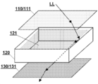
프레넬 집광 장치 및 집광식 태양에너지 시스템에 있어서, 집광 장치는 각각 적어도 하나의 집광형 프레넬 렌즈(111, 131)를 포함하는 제1 프레넬 렌즈 레이어(110) 및 제2 프레넬 렌즈 레이어(130); 및 제1 프레넬 렌즈 레이어 및 제2 프레넬 렌즈 레이어가 양단에 각각 설치되며, 제1 프레넬 렌즈 레이어로부터의 광선(LL)을 아래로 제2 프레넬 렌즈 레이어로 가이드하는 스트레이트 박스형 도광 레이어(120)를 포함한다. 2개의 프레넬 렌즈 레이어를 사용하여 각각 광선을 집광시키며, 중간에 스트레이트 박스형 도광 레이어의 협조에 의해 광선을 상부 레이어로부터 하부 레이어로 가이드하여, 집광 장치가 넓은 입사각도 적응 범위를 가질 수 있을 뿐만 아니라, 비교적 낮은 높이에서 비교적 큰 집광비를 얻을 수 있도록 함으로써 태양 추적 시스템에 대한 의존을 방지한다.In a Fresnel condensing device and a condensing solar energy system, the condensing device includes a first Fresnel lens layer 110 and a second Fresnel lens layer (including at least one condensing Fresnel lens 111, 131), respectively. 130); And a first Fresnel lens layer and a second Fresnel lens layer respectively installed at both ends, and a straight box type light guiding layer guiding the light ray LL from the first Fresnel lens layer down to the second Fresnel lens layer ( 120). Each of the two Fresnel lens layers is used to condense light, and in the middle, the light is guided from the upper layer to the lower layer in cooperation with a straight box type light guide layer, so that the condensing device can have a wide angle of incidence adaptation range. In addition, it is possible to obtain a relatively large light collection ratio at a relatively low height, thereby avoiding reliance on a solar tracking system.
Description
본 발명은 광학 소자 기술 분야 및 청정에너지원 기술 분야에 관한 것으로, 구체적으로 프레넬 렌즈를 포함한 프레넬 집광 장치 및 집광식 태양에너지 시스템에서 이의 응용에 관한 것이다.The present invention relates to the field of optical element technology and the field of clean energy sources, and specifically to a Fresnel condensing device including a Fresnel lens and its application in a condensing solar energy system.
환경 보호에 대해 나날이 중요시함에 따라, 태양에너지 시스템은 점점 더 광범위하게 응용되고 있다. 여기서 집광식 태양에너지 시스템은 태양에너지의 이용 효율을 향상시킬 수 있으므로, 점점 더 많은 관심을 받고 있다.As the importance of environmental protection is increasing day by day, solar energy systems are increasingly being applied. Here, the concentrating solar energy system is receiving more and more attention because it can improve the efficiency of using solar energy.
기존의 집광식 태양에너지 시스템에 있어서, 흔히 프레넬 렌즈를 집광 광학 소자로 사용하였으나, 프레넬 렌즈를 사용하여 광에너지 이용 장치에 직접 집광되는 광학 설계는 집광 장치의 태양광의 입사각에 대한 적응 범위를 작게 한다. 이는 기존의 태양에너지 시스템의 집광 장치가 두 방면의 제한을 받도록 하는데, 한 면으로, 이는 태양 추적 시스템과 연합하여 사용되어야만 상응하는 효과에 달성할 수 있고, 다른 한 면으로, 이의 집광비가 제한을 받는 것이다.In a conventional condensing type solar energy system, a Fresnel lens is often used as a condensing optical element, but an optical design that is directly condensed to a device using light energy using a Fresnel lens has an adaptive range for the incident angle of sunlight in the condensing device. Make it small. This allows the condensing device of the existing solar energy system to be limited in two ways, on one side, it must be used in conjunction with the solar tracking system to achieve the corresponding effect, and on the other hand, its condensing ratio is limited. To receive.
이밖에, 기존의 태양에너지 시스템의 집광 장치는 또한 높이에 관한 문제를 초래하므로, 따라서 집광 장치의 높이는 일반적으로 이의 집광비의 증가에 따라 증가된다.In addition, the condensing device of the existing solar energy system also poses a problem with respect to height, and therefore the height of the condensing device generally increases with an increase in its condensing ratio.
따라서, 보다 양호한 입사각 적응 능력을 가지고, 집광비를 증가시킬 수 있거나 시스템 높이를 감소시키는 프레넬 집광 장치를 연구할 필요가 있다.Accordingly, there is a need to study Fresnel condensing devices that have a better incidence angle adaptation ability, which can increase the condensing ratio or reduce the system height.
본 발명의 일 양태에 따르면, 각각 적어도 하나의 집광형 프레넬 렌즈를 포함하는 제1 프레넬 렌즈 레이어 및 제2 프레넬 렌즈 레이어; 및 외형이 스트레이트 박스형이고, 제1 프레넬 렌즈 레이어 및 제2 프레넬 렌즈 레이어가 스트레이트 박스형의 양단에 각각 설치되며, 제1 프레넬 렌즈 레이어로부터의 광선을 아래로 제2 프레넬 렌즈 레이어로 가이드하는 스트레이트 박스형 도광 레이어를 포함하는 프레넬 집광 장치를 제공한다.According to an aspect of the present invention, each of the first Fresnel lens layer and the second Fresnel lens layer including at least one condensed Fresnel lens; And the outer shape is a straight box type, the first Fresnel lens layer and the second Fresnel lens layer are respectively installed at both ends of the straight box type, and guide light rays from the first Fresnel lens layer down to the second Fresnel lens layer. It provides a Fresnel condensing device comprising a straight box-shaped light guide layer.
본 발명의 다른 일 양태에 따르면, 본 발명에 따른 프레넬 집광 장치 및 수광면이 프레넬 집광 장치 이후의 광행로에 설치되는 적어도 하나의 광에너지 이용 장치를 포함하는 집광식 태양에너지 시스템을 제공한다.According to another aspect of the present invention, there is provided a condensed solar energy system comprising a Fresnel condensing device and a light receiving surface according to the present invention, the at least one optical energy utilizing device being installed in an optical path after the Fresnel condensing device. .
본 발명에 따른 프레넬 집광 장치는 2개의 프레넬 렌즈 레이어를 사용하여 각각 광선을 집광시키며, 중간에 스트레이트 박스형 도광 레이어의 협조에 의해 광선을 상부 레이어로부터 하부 레이어로 가이드하여, 집광 장치가 넓은 입사각도 적응 범위를 가질 수 있을 뿐만 아니라, 비교적 낮은 높이에서 비교적 큰 집광비를 얻을 수 있도록 함으로써 태양 추적 시스템에 대한 의존을 방지한다.The Fresnel condensing device according to the present invention uses two Fresnel lens layers to condense light beams respectively, and guides the light beams from the upper layer to the lower layer in cooperation with a straight box type light guide layer in the middle, so that the condensing device has a wide incident angle. Not only can it have an adaptive range, it also prevents dependence on the solar tracking system by allowing a relatively large collection ratio at a relatively low height.
이하, 도면을 결부하여 본 발명의 구체적인 예시에 대해 상세하게 설명한다. 본문에 사용된 위치를 나타내는 “상”, “하”, “상부”, “하부” 등과 같은 용어는 단지 대향되는 위치 관계를 나타내고, 절대적 함의를 포함하지 않는다. 본문에 사용된 “제1”, “제2” 등과 같은 번호 또는 순번은 단지 식별 작용을 하며, 임의의 제한적 함의를 포함하지 않는다.Hereinafter, specific examples of the present invention will be described in detail with reference to the accompanying drawings. Terms such as “upper”, “lower”, “upper”, and “lower” indicating the position used in the text only refer to the opposing positional relationship and do not include absolute implications. Numbers or sequence numbers such as “first”, “second”, etc. used in the text merely serve as an identification function and do not include any limiting implications.
도 1은 실시예1의 프레넬 집광 장치의 모식도이다.
도 2는 실시예2의 프레넬 집광 장치의 모식도이다.
도 3은 실시예3의 집광식 태양에너지 시스템의 모식도이다.
도 4는 실시예4의 집광식 태양에너지 시스템의 모식도이다.1 is a schematic view of a Fresnel condensing device of Example 1.
2 is a schematic view of the Fresnel condensing device of Example 2.
3 is a schematic diagram of a condensed solar energy system of Example 3.
4 is a schematic view of a condensed solar energy system of Example 4.
실시예1Example 1
본 발명의 프레넬 집광 장치의 일 실시형태는 도 1을 참조할 수 있다. 도 1은 상기 장치가 종방향을 따라 분해된 후의 구조 모식도를 나타내며, 제1 프레넬 렌즈 레이어(110), 스트레이트 박스형 도광 레이어(120) 및 제2 프레넬 렌즈 레이어(130)를 포함한다.One embodiment of the Fresnel condensing device of the present invention may refer to FIG. 1. 1 shows a schematic diagram of a structure after the device is disassembled along the longitudinal direction, and includes a first Fresnel lens layer 110, a straight box type
본 발명에서의 프레넬 렌즈 레이어는 프레넬(Fresnel) 렌즈를 광학 소자로 사용하며, 각각의 렌즈 레이어는 적어도 하나의 집광형 프레넬 렌즈를 포함한다. 프레넬 렌즈는 얇은 렌즈이며, 이러한 유형의 렌즈는 경박하고 대량으로 제조하기에 편리한 이점을 갖고 있다. 본문에서 지칭된 “집광형”(또는 “광산란형”) 프레넬 렌즈는 기능적으로 광선을 렌즈의 광학중심으로 집광(또는 광학중심으로부터 확산)시키는 프레넬 렌즈를 가리키며, 이의 이뿌리면(Tooth Flank)은 일반적으로 볼록 렌즈면(도는 오목 렌즈면)에서 비롯된다. 지칭된 “선형” 프레넬 렌즈는, 선형 광산란형 프레넬 렌즈 및 선형 집광형 프레넬 렌즈를 포함하며, 렌즈의 집광 중심이 일직선이지 하나의 점에 집중되는 것이 아님을 가리킨다. 예를 들면, 선형 프레넬 렌즈의 이뿌리면은 오목형(또는 볼록형) 원기둥면, 또는 오목형(또는 볼록형) 다항식 기둥면에서 비롯될 수 있다. 프레넬 렌즈는 한 면이 이뿌리면이고, 한 면이 평면인 단일면 프레넬 렌즈일 수 있고, 양면이 모두 이뿌리면인 양면 프레넬 렌즈일 수도 있다. 각각의 프레넬 렌즈의 각각의 이뿌리면은 단지 하나의 프레넬 유닛을 포함한 간단한 렌즈면일 수 있을 뿐만 아니라, 복수의 프레넬 유닛으로 이루어진 복합 렌즈면일 수도 있으며, 이로써 복합 프레넬 렌즈로 형성된다.The Fresnel lens layer in the present invention uses a Fresnel lens as an optical element, and each lens layer includes at least one condensing Fresnel lens. Fresnel lenses are thin lenses, and this type of lens has the advantage of being lightweight and convenient for mass production. The “concentrated” (or “scattered”) Fresnel lens referred to in the text refers to a Fresnel lens that functionally condenses (or diffuses light from) the optical center of the lens, and its tooth flank (Tooth Flank). Is generally derived from a convex lens surface (or concave lens surface). The “linear” Fresnel lens referred to includes a linear light scattering Fresnel lens and a linear condensing Fresnel lens, indicating that the focusing center of the lens is straight and not concentrated at one point. For example, the toothed surface of a linear Fresnel lens may originate from a concave (or convex) cylindrical surface, or a concave (or convex) polynomial columnar surface. The Fresnel lens may be a single-sided Fresnel lens with one side being a sprinkled surface, and a single-sided plane having a flat surface, or a double-sided Fresnel lens with both sides being a sprinkled surface. Each toothed surface of each Fresnel lens may not only be a simple lens surface including only one Fresnel unit, but may also be a composite lens surface composed of a plurality of Fresnel units, thereby forming a composite Fresnel lens.
간단한 경우로서, 본 실시예에서의 제1 프레넬 렌즈 레이어 및 제2 프레넬 렌즈 레이어는 각각 하나의 집광형 간단 프레넬 렌즈(111, 131)로 형성된다. 다른 실시형태에서, 제1 프레넬 렌즈 레이어 및 제2 프레넬 렌즈 레이어는 보다 복잡한 구조를 사용할 수도 있으며, 예를 들어, 복수의 프레넬 렌즈를 포함할 수 있거나, 양면 프레넬 렌즈를 사용하거나, 복합 프레넬 렌즈를 사용한다. 바람직하게, 적어도 하나의 렌즈 레이어에서 다초점 거리 프레넬 렌즈를 사용할 수 있다. 다초점 거리 프레넬 렌즈는 이의 중심 광축과의 거리에 따라 상이한 영역으로 나뉘고, 여기서, 중심 광축과의 거리가 더 먼 영역은 더 짧은 초점 거리를 가지고, 중심 광축과의 거리가 더 가까운 영역은 더 긴 초점 거리를 가진다. 더 긴 초점 거리는 초점 거리가 무한대인 경우를 포함하며, 이 경우, 대응되는 영역은 예를 들어, 투각 영역이거나, 평면 투명 재료로 형성된다.As a simple case, the first Fresnel lens layer and the second Fresnel lens layer in this embodiment are each formed of one condensing type simple Fresnel lens 111 and 131. In another embodiment, the first Fresnel lens layer and the second Fresnel lens layer may use a more complex structure, for example, may include a plurality of Fresnel lenses, use a double-sided Fresnel lens, Use a composite Fresnel lens. Preferably, a multifocal distance Fresnel lens can be used in at least one lens layer. The multifocal distance Fresnel lens is divided into different areas according to its distance from the central optical axis, where an area farther from the central optical axis has a shorter focal length, and an area closer to the central optical axis is more It has a long focal length. Longer focal lengths include cases where the focal length is infinite, in which case the corresponding area is, for example, an open area, or is formed of a flat transparent material.
선택 가능한 실시형태로서, 제1 프레넬 렌즈 레이어 또는 제2 프레넬 렌즈 레이어의 적어도 하나의 집광형 프레넬 렌즈는 선형 집광형 프레넬 렌즈를 사용할 수 있으며, 여기서 각각의 선형 렌즈의 집광 중심선은 기본적으로 전체 집광 장치의 광축(또는 중심축, 즉 태양광이 수직으로 입사되는 방향)에 수직된다. 바람직하게, 상이한 레이어의 선형 집광형 프레넬 렌즈의 집광 중심선은 서로 수직되며, 따라서 2개의 선형의 프레넬 렌즈 레이어로 하나의 2차원(즉 단일한 중심 광축 및 초점을 가지는 것) 프레넬 렌즈를 구현한다. 이러한 구조는 초평면에서 균일한 광도 분포를 얻거나, 처리하기 쉬운 렌즈 조합을 통해 복잡한 광학 설계를 구현하는데 도움이 된다.As a selectable embodiment, at least one condensed Fresnel lens of the first Fresnel lens layer or the second Fresnel lens layer may use a linear condensed Fresnel lens, wherein the condensed centerline of each linear lens is basically Therefore, it is perpendicular to the optical axis (or the central axis, that is, the direction in which sunlight enters vertically) of the entire condensing device. Preferably, the condensing centerlines of the linear condensing Fresnel lenses of different layers are perpendicular to each other, so that one two-dimensional (i.e., having a single central optical axis and focus) Fresnel lens with two linear Fresnel lens layers. Implement it. This structure helps to achieve a uniform optical distribution in the hyperplane, or to implement a complex optical design through easy-to-handle lens combinations.
스트레이트 박스형 도광 레이어(120)의 외형은 스트레이트 박스형이고, 제1 프레넬 렌즈 레이어 및 제2 프레넬 렌즈 레이어는 각각 상기 스트레이트 박스형의 양단에 설치되며, 상기 스트레이트 박스형 도광 레이어는 제1 프레넬 렌즈 레이어로부터의 광선을 아래로 제2 프레넬 렌즈 레이어로 가이드한다. 스트레이트 박스형 도광 레이어의 튜브벽은 2개의 렌즈 레이어(즉 전체 집광 장치의 광축 방향과 기본적으로 일치함)에 수직되며, 이는 투명할 수 있고, 적어도 일부 내벽에 반사경면을 설치할 수도 있다.The outer shape of the straight box type
다양한 광학 설계를 이용하여 스트레이트 박스형 도광 레이어의 도광 기능을 구현할 수 있으며, 예를 들어, 내벽의 반사경면을 이용하여 도광할 수 있거나, 스트레이트 박스형 도광 레이어의 튜브벽과 제1 프레넬 렌즈 레이어 및 제2 프레넬 렌즈 레이어는 함께 둘러싸여 폐쇄된 제1 공간을 형성하며, 제1 공간에는 고압 가스 또는 광학 가스로 충전되고, 따라서 입사 광선을 아래로 편향시키는데 도움을 주며, 지칭된 광학 가스는 하나의 표준 대기압에서 굴절율이 1보다 큰 가스를 가리키거나, 스트레이트 박스형 도광 레이어의 내부 공간에 광선의 편향을 돕는 다른 광학 소자를 가리킨다.A light guiding function of a straight box type light guiding layer may be implemented using various optical designs, for example, light guiding using a reflection mirror of an inner wall, or a tube wall of the straight box type light guiding layer and a first Fresnel lens layer and agent The two Fresnel lens layers are enclosed together to form a closed first space, the first space being filled with high pressure gas or optical gas, thus helping to deflect incident light downward, and the optical gas referred to is one standard Points to a gas with a refractive index greater than 1 at atmospheric pressure, or other optical element that assists the deflection of light rays in the inner space of a straight box-shaped light guide layer.
본 실시예에서, 튜브 내벽이 반사경면인 구조를 사용하며, 폐쇄된 제1 공간에는 광학 가스(121)로 충전되고, 입사광선(LL)은 상부 렌즈 레이어의 집광 및 스트레이트 박스형 도광 레이어의 편향에 의해 하부의 렌즈 레이어로 가이드된다.In this embodiment, a structure in which the inner wall of the tube is a reflective mirror surface is filled with the
본 실시예에서, 스트레이트 박스형 도광 레이어의 횡단면은 사각형이며, 다른 실시형태에서, 상이한 횡단면 형상을 사용할 수도 있다. 복수의 집광 장치의 긴밀한 배열 또는 통합을 편리하게 하기 위해, 스트레이트 박스형의 횡단면 형상은 바람직하게, 다양한 규칙적이고 제조하기에 편리한 형상으로부터 선택될 수 있고, 예를 들어, 사각형, 육각형, 원형 등으로부터 선택될 수 있다.In this embodiment, the cross-section of the straight box-shaped light guide layer is square, and in other embodiments, different cross-sectional shapes may be used. In order to facilitate the close arrangement or integration of a plurality of condensing devices, the straight box-shaped cross-sectional shape may preferably be selected from various regular and convenient manufacturing shapes, for example, selected from square, hexagon, circular, and the like. Can be.
본 실시예의 프레넬 집광 장치는 비교적 높은 집광비를 구현할 수 있는데 비해 높이가 비교적 낮으며, 이는 임의의 광에너지 또는 전자기 에너지 수신 소자와 결합할 수 있고, 집광식 광에너지 또는 전자기 에너지 수신 시스템으로 형성되며, 예를 들어, 집광식 태양에너지 시스템에 응용된다.The Fresnel condensing device of the present embodiment can achieve a relatively high condensing ratio, but its height is relatively low, which can be combined with any optical energy or electromagnetic energy receiving element, and is formed of a condensing optical energy or electromagnetic energy receiving system. And, for example, it is applied to a condensed solar energy system.
실시예2Example 2
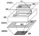
본 발명의 프레넬 집광 장치의 다른 일 실시형태는 도 2를 참조할 수 있다. 도 2는 상기 장치가 종방향을 따라 분해된 후의 구조 모식도를 나타내며, 제1 프레넬 렌즈 레이어(210), 스트레이트 박스형 도광 레이어(220), 제2 프레넬 렌즈 레이어(230) 및 원추형 도광 레이어(240)를 포함한다.Another embodiment of the Fresnel condensing device of the present invention may refer to FIG. 2. Figure 2 shows a schematic structural diagram of the device after being disassembled along the longitudinal direction, the first Fresnel lens layer 210, the straight box type
본 실시예에서, 2개의 렌즈 레이어와 스트레이트 박스형 도광 레이어의 기본 구조 관계는 실시예1과 유사하며, 주요 구별되는 점은 하기와 같다.In this embodiment, the basic structural relationship between the two lens layers and the straight box-type light guide layer is similar to that of Example 1, and the main differences are as follows.
1.제1 프레넬 렌즈 레이어(210)는 바람직하게 다초점 거리 프레넬 렌즈(211)를 사용하며, 이 표면은 2개의 형상이 유사한 동심인 영역으로 나뉘고, 여기서, 중심 광축과의 거리가 더 먼 영역(주변 영역(A01))은 더 짧은 초점 거리를 가지며, 중심축과의 거리가 더 가까운 영역(중심 영역(A02))은 더 긴 초점 거리를 갖는다.1. The first Fresnel lens layer 210 preferably uses a multifocal distance Fresnel lens 211, the surface of which is divided into two concentric regions of similar shape, where the distance from the central optical axis is more The far area (the peripheral area A01) has a shorter focal length, and the area closer to the center axis (the center area A02) has a longer focal length.
2.제2 프레넬 렌즈 레이어(230)는 바람직하게 다초점 거리 프레넬 렌즈(231)를 사용하며, 이는 단지 주변 영역(B01)이 프레넬 렌즈면을 가지고, 중심 영역(B02)은 투각된다.2. The second Fresnel lens layer 230 preferably uses a multifocal distance Fresnel lens 231, which only has the peripheral area B01 having a Fresnel lens surface, and the central area B02 is hollowed out. .
3.스트레이트 박스형 도광 레이어(220)에 튜브벽이 선형 광산란형 프레넬 렌즈로 형성된 광산란 튜브(222)가 더 포함되며, 상기 광산란 튜브의 길이 연장 방향은 스트레이트 박스형 도광 레이어와 일치하고, 스트레이트 박스형 도광 레이어의 내부 공간에 설치되며, 각각의 선형 광산란형 프레넬 렌즈의 집광 중심선은 광산란 튜브의 길이 연장 방향과 수직된다.3. The straight box type
광산란 튜브(222)는 입사광을 스트레이트 박스의 하단으로 산란시킬 수 있으며, 스트레이트 박스형 도광 레이어가 광축을 빗나가는 입사 광선의 편이 기능을 강화시키고, 이후의 광학 소자가 광선(LL)을 광에너지 이용 장치로 최종 가이드하는데 유리하다. 광산란 튜브의 횡단면 형상은 이 외부를 둘러싼 스트레이트 박스형 도광 레이어의 튜브벽의 횡단면 형상과 동일하거나 상이할 수 있으며, 본 실시예에서는 사각형을 사용한다.The
원추형 도광 레이어(240)는 제2 프레넬 렌즈 레이어(230) 하부에 설치되고, 적어도 하나의 반사식의 원추형 도광 튜브(241)를 포함하며, 이의 내벽의 전부 또는 적어도 일부는 반사경면이고, 상부 개구는 크고 하부 개구는 작으며, 제2 프레넬 렌즈 레이어로 집광된 광선을 따라 원추형 도광 튜브의 상부로부터 입사되어 하부로 가이드된다. 원추형 도광 튜브의 횡단일면 형상은 사각형, 육각형, 원형 등일 수 있다.The conical light guide layer 240 is installed under the second Fresnel lens layer 230, and includes at least one reflective conical light guide tube 241, all or at least part of its inner wall is a reflective mirror, and the upper part The opening is large and the bottom opening is small, and is incident from the top of the conical light guide tube along the light beam condensed into the second Fresnel lens layer and guided to the bottom. The cross-sectional shape of the conical light guide tube may be square, hexagonal, circular, or the like.
원추형 도광 튜브(241)의 하부는 이에 광에너지 이용 장치를 설치하여 집광식 태양에너지 시스템으로 형성하는데 편리하도록 폐쇄될 수 있거나, 광에너지 이용 장치로 원추형 도광 튜브의 하부를 폐쇄할 수도 있다. 원추형 도광 튜브의 하부가 폐쇄된 후, 이의 튜브벽과 제2 프레넬 렌즈 레이어는 함께 둘러싸여 폐쇄된 제2 공간을 형성하며, 여기서 고압 가스 또는 광학 가스를 보다 더 충전하여 집광비를 증가시킬 수 있다.The lower portion of the conical light guide tube 241 may be conveniently closed to form a condensed solar energy system by installing a light energy using device thereon, or the lower portion of the conical light guide tube with the light energy using device. After the lower portion of the conical light guide tube is closed, its tube wall and the second Fresnel lens layer are surrounded together to form a closed second space, in which high pressure gas or optical gas is further filled to increase the light collection ratio. .
집광식 태양에너지 시스템을 구현하는 간단한 경우로서, 단일면이 수광되는 광에너지 이용 장치, 예를 들어, 단일면이 수광되는 광전지 패널(250)을 원추형 도광 튜브의 하부에 설치할 수 있고, 이의 수광면은 원추형 도광 튜브의 상부를 향한다. 본 발명에서 지칭된 “광전지 패널”은 일반적으로 다양한 재료로 이루어진 광전지 패널, 광전지 박막, 양자점 광전지 재료 등과 같은 다양한 유형의 광전 변환 소자를 가리킨다. As a simple case of implementing a condensing solar energy system, a device for using light energy that receives a single surface, for example, a
실시예3Example 3
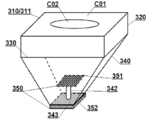
본 발명의 집광식 태양에너지 시스템의 일 실시형태는 도 3을 참조할 수 있다. 도 3은 상기 시스템이 조립된 후의 구조 모식도를 나타내며, 제1 프레넬 렌즈 레이어(310), 스트레이트 박스형 도광 레이어(320), 제2 프레넬 렌즈 레이어(330), 원추형 도광 레이어(340) 및 광에너지 이용 장치(350)를 포함한다.One embodiment of the condensed solar energy system of the present invention may refer to FIG. 3. 3 shows a schematic diagram of the structure after the system is assembled, the first Fresnel lens layer 310, the straight box type
본 실시예에서, 2개의 렌즈 레이어와 2개의 도광 레이어의 기본 구조 관계는 실시예2와 유사하며, 주요 구별되는 점은 하기와 같다.In this embodiment, the basic structural relationship between the two lens layers and the two light guide layers is similar to that of the second embodiment, and the main differences are as follows.
제1 프레넬 렌즈 레이어(310)에 사용된 다초점 거리 프레넬 렌즈(311)의 표면이 분할된 2개의 영역의 형상은 상이하며, 중심 영역(C02)은 원형이고, 주변 영역(C01)은 사각형이다. 이는 본 발명의 구조에 따른 광행로 설계 및 외형 설계에서의 원활성을 구현한다.The shapes of the two regions where the surfaces of the multifocal distance Fresnel lens 311 used in the first Fresnel lens layer 310 are divided are different, the central region C02 is circular, and the peripheral region C01 is It is square. This realizes smoothness in optical path design and external design according to the structure of the present invention.
이밖에, 본 실시예에서의 광에너지 이용 장치(350)는 복합형이며, 즉 광전지 패널(351)을 제외한 이외 열전기 변환 소자(352)를 더 포함한다. 열전기 변환 소자는 광전지 패널에 의해 방열되는 과정에서 열에너지를 전기에너지로 추가로 변환시키도록 광전지 패널의 외부로 방열되는 열전도 경로에 설치될 수 있다. 열전기 변환 소자는 예를 들어 열전기 효과를 갖는 반도체 소자를 사용할 수 있다.In addition, the light
본 실시예에서, 광전지 패널(351) 및 열전기 변환 소자(352)는 분리되게 설치되며, 여기서 광전지 패널(351)은 원추형 도광 튜브 내에 설치되고, 열전도에 의한 지지부재(342)는 원추형 도광 튜브에 고정되며, 이 경우, 원추형 도광 튜브의 하부는 반사경면(343)에 의해 폐쇄될 수 있다. 열전기 변환 소자(352)는 원추형 도광 튜브의 하부의 배면에 열전도되도록 부착된다. 이 경우, 광전지 패널(351)은 바람직하게 양면이 수광되는 광전지 패널을 사용하여 광에너지 이용 효율을 향상시킬 수 있다.In this embodiment, the
다른 실시형태에서, 예를 들어 도 2에 도시된 바와 같이, 단일면이 수광되는 광전지 패널(250)을 원추형 도광 튜브의 하부에 설치할 경우, 열전기 변환 소자는 또한 단일면이 수광되는 광전지 패널의 배면에 열전도되도록 부착될 수 있어 복합형의 광에너지 이용 장치가 하나의 전체로 형성되도록 한다.In another embodiment, for example, as shown in FIG. 2, when a single-sided
실시예4Example 4
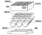
본 발명의 집광식 태양에너지 시스템의 다른 일 실시형태는 도 4를 참조할 수 있다. 도 4는 상기 시스템이 종방향을 따라 분해된 후의 구조 모식도를 나타내며, 제1 프레넬 렌즈 레이어(410), 스트레이트 박스형 도광 레이어(420), 제2 프레넬 렌즈 레이어(430), 원추형 도광 레이어(440), 광에너지 이용 장치(450) 및 보텀 트레이(460)를 포함한다.Another embodiment of the condensed solar energy system of the present invention may refer to FIG. 4. 4 is a schematic structural diagram of the system after being disassembled along the longitudinal direction, the first Fresnel lens layer 410, the straight box type
본 실시예는 제조하기 쉽고 원가를 감소시키도록 본 발명의 시스템의 통합화의 구현 방식을 나타낸다. 본 발명에 따른 프레넬 집광 장치는 개별적으로 제조된 후 다시 복수로 통합될 수 있으며, 각각의 레이어는 복수의 유닛으로 이루어질 수 있고, 각각의 레이어는 개별적으로 통합된 후 다시 전체적으로 조합되거나, 일부 레이어는 통합된 다중 유닛 구조를 사용하고, 일부 레이어는 전체가 단일 요소로 형성되는 구조를 사용한다.This embodiment represents an implementation manner of the integration of the system of the present invention to be easy to manufacture and reduce cost. The Fresnel condensing device according to the present invention may be individually manufactured and then integrated into a plurality, and each layer may be composed of a plurality of units, and each layer may be individually combined and then combined again, or some layers Uses an integrated multi-unit structure, and some layers use a structure in which the whole is formed of a single element.
예시로서, 본 실시예는 혼합 경우를 나타내며, 여기서, As an example, this example shows a mixing case, where:
제1 프레넬 렌즈 레이어(410)는 어레이로 배열된 복수의 집광형 프레넬 렌즈(411)를 포함하며, 각각의 집광형 프레넬 렌즈(411)는 간단한 프레넬 렌즈일 수 있고, 복합 프레넬 렌즈일 수도 있으며, 전체 렌즈 레이어(410)는 복수의 유닛으로 구성되어 형성될 수 있고, 하나의 전체일 수도 있으며, 각각의 렌즈(411)는 이의 이뿌리면의 패턴에 의해 분할된다.The first Fresnel lens layer 410 includes a plurality of condensed Fresnel lenses 411 arranged in an array, and each condensed Fresnel lens 411 may be a simple Fresnel lens, and a composite Fresnel. It may be a lens, or the entire lens layer 410 may be formed of a plurality of units, or may be one whole, and each lens 411 is divided by a pattern of its root surface.
제2 프레넬 렌즈 레이어(430)는 어레이로 배열된 복수의 집광형 프레넬 렌즈(431)를 포함하며, 각각은 중심 영역이 투각되는 다초점 거리 프레넬 렌즈이다.The second Fresnel lens layer 430 includes a plurality of condensed Fresnel lenses 431 arranged in an array, each of which is a multifocal distance Fresnel lens in which a central region is open.
스트레이트 박스형 도광 레이어(420)는 어레이로 배열된 복수의 스트레이트 박스형 도광 튜브(미도시)로 형성될 수 있고, 각각의 스트레이트 박스형 도광 튜브는 한 쌍의 렌즈(411) 및 렌즈(431)에 대응되며, 전체가 하나의 큰 도광 스트레이트 박스일 수도 있다.The straight box type
원추형 도광 레이어(440)는 어레이로 배열된 복수의 원추형 도광 튜브(441)를 포함하며, 따라서 대응되게, 광에너지 이용 장치(450)는 각각 원추형 도광 튜브(441)의 하부에 설치된 복수의 광전지 패널(451)을 포함한다.The conical light guide layer 440 includes a plurality of conical light guide tubes 441 arranged in an array, so correspondingly, the light energy utilizing device 450 is provided with a plurality of photovoltaic panels, respectively, installed underneath the conical light guide tube 441. 451.
광에너지 이용 장치의 방열 속도를 향상시킴과 동시에 확산되는 열량을 이용하기 위해, 더 바람직하게, 본 실시예는 원추형 도광 레이어(440) 하부에 설치되며, 원추형 도광 레이어와 함께 둘러싸여 폐쇄된 제3 공간을 형성하는 보텀 트레이(460)를 포함하며, 제3 공간에 작업 매질이 수용될 수 있고, 이러한 작업 매질은 광전지 패널(451)과 열전도 연결된다. 바람직하게, 작업 매질은 비교적 큰 열용량을 갖는 물질일 수 있으며, 고체거나 유체일 수 있고, 작업 매질에 의해 흡수되는 열량은 추가 열전도 또는 작업 매질의 순환에 의해 외부에 사용되도록 제공된다. 사용된 유체 작업 매질은 물, 오일, 냉각제, 압축 가스 등으로부터 선택될 수 있다. 이 경우, 보텀 트레이에 작업 매질을 유입하고 유출하도록 제공되는 입구와 출구가 더 설치될 수 있다. 액체 작업 매질의 순환 시스템은 개방식일 수 있고 폐쇄식일 수도 있으며, 작업 매질의 유형과 예기하는 열에너지 이용 형태에 따라 결정될 수 있다. 바람직하게, 광전 변환 소자와 작업 매질 사이의 열전도 경로에 열전기 변환 소자(미도시)가 더 설치될 수 있으며, 예를 들어, 열전기 변환 소자를 원추형 도광 튜브(441) 하부의 배면에 설치하여 작업 매질 중에 침포될 수 있도록 한다.In order to improve the heat dissipation rate of the light energy-using device and to utilize the amount of heat that is diffused at the same time, more preferably, this embodiment is installed under the conical light guide layer 440 and is enclosed with a conical light guide layer to close the third space. It includes a
일 바람직한 실시형태로서, 본 실시예는 압전 진동편(471) 및 이의 구동 회로(도면에 도시되지 않음)를 포함하는 압전 진동기(470)를 더 포함한다. 압전 진동편(471)은 제1 프레넬 렌즈 레이어(410)와 기계적으로 연결(예를 들어, 스트레이트 박스형 도광 레이어(420)의 외측에 고정됨)되어 제1 프레넬 렌즈 레이어(410)를 진동하도록 구동한다. 진동기는 예를 들어 집광 장치의 수광면의 자동 세척, 도는 제설, 디아이싱(deicing) 등에 사용될 수 있다. 다른 실시형태에서, 압전 진동편은 다른 위치에 고정될 수도 있으며, 본 발명은 이에 한정되지 않는다.In one preferred embodiment, the present embodiment further includes a piezoelectric vibrator 470 including a piezoelectric vibrating piece 471 and its driving circuit (not shown in the figure). The piezoelectric vibrating piece 471 is mechanically connected to the first Fresnel lens layer 410 (for example, fixed to the outside of the straight box type light guide layer 420) to vibrate the first Fresnel lens layer 410 Drive. The vibrator can be used, for example, for automatic cleaning, turning snow removal, deicing, etc. of the light-receiving surface of the condensing device. In other embodiments, the piezoelectric vibrating element may be fixed in other positions, and the present invention is not limited thereto.
이상, 구체적인 예를 응용하여 본 발명의 원리 및 실시형태에 대해 설명하며, 이상 실시형태는 단지 본 발명을 이해하는데 도움을 줄 뿐, 본 발명을 한정하려는 것으로 이해해서는 안됨을 이해해야 할 것이다. 본 기술분야의 통상의 기술자는 본 발명의 사상에 따라 상기 구체적인 실시형태에 대해 변경을 진행할 수 있다.Above, the principles and embodiments of the present invention will be described by applying specific examples, and it should be understood that the above embodiments merely help to understand the present invention and should not be understood as limiting the present invention. Those skilled in the art can make changes to the above specific embodiments according to the spirit of the present invention.
Claims (13)
각각 적어도 하나의 집광형 프레넬 렌즈를 포함하는 제1 프레넬 렌즈 레이어 및 제2 프레넬 렌즈 레이어; 및
외형이 스트레이트 박스형이고, 제1 프레넬 렌즈 레이어 및 제2 프레넬 렌즈 레이어가 상기 스트레이트 박스형의 양단에 각각 설치되며, 제1 프레넬 렌즈 레이어로부터의 광선을 아래로 제2 프레넬 렌즈 레이어로 가이드하는 스트레이트 박스형 도광 레이어를 포함하는 것을 특징으로 하는 프레넬 집광 장치.Fresnel condensing device,
A first Fresnel lens layer and a second Fresnel lens layer each including at least one condensing Fresnel lens; And
The outer shape is a straight box type, and a first Fresnel lens layer and a second Fresnel lens layer are respectively installed at both ends of the straight box type, and guide light rays from the first Fresnel lens layer down to the second Fresnel lens layer. Fresnel condensing device comprising a straight box-shaped light guide layer.
상기 스트레이트 박스형 도광 레이어의 내벽은 반사경면이거나;
상기 스트레이트 박스형 도광 레이어의 튜브벽과 제1 프레넬 렌즈 레이어 및 제2 프레넬 렌즈 레이어는 함께 둘러싸여 폐쇄된 제1 공간을 형성하고, 제1 공간에는 고압 가스 또는 광학 가스로 충전되거나;
상기 스트레이트 박스형 도광 레이어는 튜브벽이 선형 광산란형 프레넬 렌즈로 형성된 광산란 튜브를 더 포함하며, 상기 광산란 튜브의 길이 연장 방향은 상기 스트레이트 박스형 도광 레이어와 일치하고, 상기 스트레이트 박스형 도광 레이어의 내부 공간에 설치되며, 상기 선형 광산란형 프레넬 렌즈의 집광 중심선은 상기 길이 연장 방향과 수직되는 것을 특징으로 하는 프레넬 집광 장치.According to claim 1,
The inner wall of the straight box type light guide layer is a reflective mirror surface;
The tube wall of the straight box type light guide layer and the first Fresnel lens layer and the second Fresnel lens layer are surrounded together to form a closed first space, and the first space is filled with high pressure gas or optical gas;
The straight box type light guide layer further includes a light scattering tube having a tube wall formed of a linear light scattering type Fresnel lens, and a length extension direction of the light scattering tube coincides with the straight box type light guide layer, and is provided in an inner space of the straight box type light guide layer. Fresnel condensing device, characterized in that the center line of the light condensing of the linear light scattering type Fresnel lens is perpendicular to the longitudinal direction.
제1 프레넬 렌즈 레이어 또는 제2 프레넬 렌즈 레이어의 적어도 하나의 집광형 프레넬 렌즈는 다초점 거리 프레넬 렌즈이거나 양면 프레넬 렌즈이거나 복합 프레넬 렌즈이며,
상기 다초점 거리 프레넬 렌즈는 이의 중심 광축과의 거리에 따라 상이한 영역으로 나뉘고, 중심 광축과의 거리가 더 먼 영역은 더 짧은 초점 거리를 가지며, 중심 광축과의 거리가 더 가까운 영역은 더 긴 초점 거리를 가지고, 상기 더 긴 초점 거리는 초점 거리가 무한대인 경우를 포함하는 것을 특징으로 하는 프레넬 집광 장치.The method according to claim 1 or 2,
At least one condensed Fresnel lens of the first Fresnel lens layer or the second Fresnel lens layer is a multifocal distance Fresnel lens, a double-sided Fresnel lens, or a composite Fresnel lens,
The multifocal distance Fresnel lens is divided into different regions according to its distance from the central optical axis, an area farther from the central optical axis has a shorter focal length, and an area closer to the central optical axis is longer. A fresnel condensing device having a focal length, wherein the longer focal length includes a case where the focal length is infinite.
제1 프레넬 렌즈 레이어 또는 제2 프레넬 렌즈 레이어의 적어도 하나의 집광형 프레넬 렌즈는 선형 집광형 프레넬 렌즈이며, 상이한 레이어의 선형 집광형 프레넬 렌즈의 집광 중심선은 서로 수직되는 것을 특징으로 하는 프레넬 집광 장치.The method according to any one of claims 1 to 3,
At least one condensing Fresnel lens of the first Fresnel lens layer or the second Fresnel lens layer is a linear condensing Fresnel lens, and the condensing centerlines of the linear condensing Fresnel lenses of different layers are perpendicular to each other. Fresnel condensing device.
제1 프레넬 렌즈 레이어는 어레이로 배열된 복수의 집광형 프레넬 렌즈를 포함하고;
제2 프레넬 렌즈 레이어는 어레이로 배열된 복수의 집광형 프레넬 렌즈를 포함하며;
상기 스트레이트 박스형 도광 레이어는 어레이로 배열된 복수의 스트레이트 박스형 도광 튜브를 포함하고, 상기 스트레이트 박스형 도광 튜브의 횡단면 형상은 사각형, 육각형, 원형으로부터 선택되는 특징 중 적어도 하나를 구비하는 것을 특징으로 하는 프레넬 집광 장치.The method according to any one of claims 1 to 4,
The first Fresnel lens layer includes a plurality of condensed Fresnel lenses arranged in an array;
The second Fresnel lens layer includes a plurality of condensed Fresnel lenses arranged in an array;
The straight box type light guide layer includes a plurality of straight box type light guide tubes arranged in an array, and the cross-sectional shape of the straight box type light guide tube has at least one of features selected from square, hexagon, and circle. condenser.
제2 프레넬 렌즈 레이어 하부에 설치되는 원추형 도광 레이어를 더 포함하며, 상기 원추형 도광 레이어는 적어도 하나의 반사식의 원추형 도광 튜브를 포함하고, 이의 내벽의 적어도 일부는 반사경면이며, 상부 개구는 크고 하부 개구는 작으며, 제2 프레넬 렌즈 레이어에 의해 집광된 광선은 상기 원추형 도광 튜브의 상부로부터 입사되는 것을 특징으로 하는 프레넬 집광 장치.The method according to any one of claims 1 to 5,
Further comprising a conical light guide layer installed under the second Fresnel lens layer, the conical light guide layer comprises at least one reflective conical light guide tube, at least a portion of its inner wall is a reflective mirror, and the upper opening is large The lower opening is small, and the light collected by the second Fresnel lens layer is incident on the Fresnel light collecting device, characterized in that it is incident from the upper portion of the conical light guide tube.
상기 원추형 도광 튜브의 하부는 폐쇄되고 이의 튜브벽과 제2 프레넬 렌즈 레이어는 함께 둘러싸여 폐쇄된 제2 공간을 형성하는 것을 특징으로 하는 프레넬 집광 장치.The method of claim 6,
The lower portion of the conical light guide tube is closed and its tube wall and the second Fresnel lens layer are surrounded together to form a closed second space Fresnel condensing device.
압전 진동편 및 이의 구동 회로를 포함하는 압전 진동기를 더 포함하며, 상기 압전 진동편은 제1 프레넬 렌즈 레이어와 기계적으로 연결되어 제1 프레넬 렌즈 레이어를 진동하도록 구동하는 것을 특징으로 하는 프레넬 집광 장치.The method according to any one of claims 1 to 7,
Further comprising a piezoelectric vibrating element and a piezoelectric vibrator including a driving circuit thereof, the piezoelectric vibrating element is mechanically connected to the first Fresnel lens layer Fresnel characterized in that to drive the first Fresnel lens layer to vibrate condenser.
제1항 내지 제8항 중 어느 한 항에 따른 프레넬 집광 장치; 및
수광면이 상기 프레넬 집광 장치 이후의 광행로에 설치되는 적어도 하나의 광에너지 이용 장치를 포함하는 것을 특징으로 하는 집광식 태양에너지 시스템.Condensed solar energy system,
The Fresnel condensing device according to any one of claims 1 to 8; And
A condensing solar energy system, characterized in that the light-receiving surface comprises at least one optical energy utilization device installed in an optical path after the Fresnel condensing device.
제6항 내지 제8항 중 어느 한 항에 따른 프레넬 집광 장치를 포함하고,
상기 광에너지 이용 장치는 상기 원추형 도광 튜브의 하부에 설치되거나, 상기 원추형 도광 튜브 내에 설치되며, 상기 광에너지 이용 장치는 광전 변환 소자를 포함하는 것을 특징으로 하는 집광식 태양에너지 시스템.The method of claim 9,
Claims 6 to 8 comprises a Fresnel condensing device according to any one of the preceding,
The light energy utilization device is installed under the conical light guide tube, or is installed in the conical light guide tube, wherein the light energy utilization device comprises a photoelectric conversion element.
상기 광전 변환 소자는 단일면이 수광되는 광전지 패널이고, 상기 원추형 도광 튜브의 하부에 설치되며, 수광면은 상기 원추형 도광 튜브의 상부를 향하거나,
상기 광전 변환 소자는 양면이 수광되는 광전지 패널이며, 상기 원추형 도광 튜브 내에 설치되고, 열전도 지지부재에 의해 원추형 도광 튜브에 고정되며, 상기 원추형 도광 튜브의 하부는 반사경면에 의해 폐쇄되는 것을 특징으로 하는 집광식 태양에너지 시스템.The method of claim 10,
The photoelectric conversion element is a photovoltaic panel on which a single surface is received, and is installed under the conical light guide tube, and the light receiving surface is directed toward an upper portion of the conical light guide tube,
The photoelectric conversion element is a photovoltaic panel that receives both sides, is installed in the conical light guide tube, is fixed to the conical light guide tube by a heat conduction support member, characterized in that the lower portion of the conical light guide tube is closed by a reflective mirror Condensed solar energy system.
상기 원추형 도광 레이어의 하부에 설치되며, 상기 원추형 도광 레이어와 함께 둘러싸여 폐쇄된 제3 공간을 형성하는 보텀 트레이를 더 포함하며, 제3 공간에 작업 매질이 수용되고, 상기 작업 매질은 상기 광전 변화 소자와 열전도 연결되며, 상기 작업 매질은 물, 오일, 냉각제, 압축 가스로부터 선택되는 것을 특징으로 하는 집광식 태양에너지 시스템.The method of claim 10 or 11,
It is installed under the conical light guide layer, and further includes a bottom tray surrounded by the conical light guide layer to form a closed third space, a working medium is accommodated in a third space, and the working medium is the photoelectric conversion element. And a heat conduction connection, wherein the working medium is selected from water, oil, coolant, and compressed gas.
상기 광에너지 이용 장치는 상기 광전 변환 소자에 의해 방열되는 열전도 경로에 설치되는 열전기 변환 소자를 더 포함하는 것을 특징으로 하는 집광식 태양에너지 시스템.The method according to any one of claims 10 to 12,
The light energy utilizing device further comprises a thermoelectric conversion element installed in a heat conduction path radiated by the photoelectric conversion element.
Applications Claiming Priority (1)
| Application Number | Priority Date | Filing Date | Title |
|---|---|---|---|
| PCT/CN2017/091414 WO2019006579A1 (en) | 2017-07-03 | 2017-07-03 | Fresnel condenser device and condenser-type solar energy system |
Publications (1)
| Publication Number | Publication Date |
|---|---|
| KR20200031116A true KR20200031116A (en) | 2020-03-23 |
Family
ID=64950532
Family Applications (1)
| Application Number | Title | Priority Date | Filing Date |
|---|---|---|---|
| KR1020207002818A KR20200031116A (en) | 2017-07-03 | 2017-07-03 | Fresnel condensing unit and condensing solar system |
Country Status (10)
| Country | Link |
|---|---|
| US (1) | US20210336581A1 (en) |
| EP (1) | EP3648179A4 (en) |
| JP (1) | JP6916315B2 (en) |
| KR (1) | KR20200031116A (en) |
| CN (1) | CN110741481A (en) |
| AU (1) | AU2017422421B2 (en) |
| BR (1) | BR112019027997A2 (en) |
| CA (1) | CA3068080A1 (en) |
| MY (1) | MY194521A (en) |
| WO (1) | WO2019006579A1 (en) |
Family Cites Families (22)
| Publication number | Priority date | Publication date | Assignee | Title |
|---|---|---|---|---|
| US4284839A (en) * | 1978-12-18 | 1981-08-18 | Johnson Steven A | Internal refractor focusing solar energy collector apparatus and method |
| JPS59110176A (en) * | 1982-12-15 | 1984-06-26 | Sumitomo Electric Ind Ltd | Focusing type solar ray power generator |
| JPS61145861A (en) * | 1984-12-19 | 1986-07-03 | Mitsubishi Electric Corp | Solid-state image pickup element |
| US5886821A (en) * | 1997-10-02 | 1999-03-23 | Fresnel Technologies, Inc. | Lens assembly for miniature motion sensor |
| JP2000091612A (en) * | 1998-09-08 | 2000-03-31 | Honda Motor Co Ltd | Condensing and tracking power generator |
| JP2005105789A (en) * | 2003-09-30 | 2005-04-21 | Seratekku:Kk | Snow remover using piezoelectric vibration plate |
| JP2006332113A (en) * | 2005-05-23 | 2006-12-07 | Sharp Corp | Concentrating solar power generation module and solar power generator |
| US20100012171A1 (en) * | 2008-03-05 | 2010-01-21 | Ammar Danny F | High efficiency concentrating photovoltaic module with reflective optics |
| CN101355114A (en) * | 2008-09-24 | 2009-01-28 | 江苏白兔科创新能源股份有限公司 | Condensation photovoltaic electrification CPV die set |
| JP2010166010A (en) * | 2009-01-13 | 2010-07-29 | Tsutomu Watanabe | Converging closed space three-dimensional solar cell |
| TWI494633B (en) * | 2010-07-23 | 2015-08-01 | Hon Hai Prec Ind Co Ltd | Light focus device |
| CN102338929B (en) * | 2010-07-27 | 2016-05-11 | 鸿富锦精密工业(深圳)有限公司 | Beam condensing unit |
| TW201214732A (en) * | 2010-09-24 | 2012-04-01 | Foxsemicon Integrated Tech Inc | Light concentrator and solar cell apparatus |
| JP2012252228A (en) * | 2011-06-03 | 2012-12-20 | Dainippon Printing Co Ltd | Method for manufacturing reflective screen and reflective screen |
| CN102620232A (en) * | 2012-03-28 | 2012-08-01 | 陕西科技大学 | Transmission-type sunlight tunnel direct enhanced illumination device |
| JP2014035803A (en) * | 2012-08-07 | 2014-02-24 | Konica Minolta Inc | Optical system for solar light collection, and solar light collection system |
| US9415428B2 (en) * | 2013-08-15 | 2016-08-16 | California Institute Of Technology | Methods and systems for self-cleaning of photovoltaic panels |
| CN104456980B (en) * | 2014-12-09 | 2017-07-28 | 中国科学院工程热物理研究所 | A kind of secondary condensation reflection and transmission type parabolic trough type solar thermal collector |
| KR20170092674A (en) * | 2014-12-10 | 2017-08-11 | 볼리미디어 홀딩즈 컴퍼니 리미티드 | Electromagnetic radiation sensing system |
| JP2016138911A (en) * | 2015-01-26 | 2016-08-04 | 株式会社クラレ | Fresnel lens, light-condensing type solar power generation module and light-condensing type solar power generation device |
| CN106533328B (en) * | 2015-09-11 | 2018-05-25 | 博立码杰通讯(深圳)有限公司 | Integrated solar utilizes apparatus and system |
| CN206099878U (en) * | 2016-10-20 | 2017-04-12 | 博立码杰通讯(深圳)有限公司 | Light collecting light energy receiving arrangement |
-
2017
- 2017-07-03 JP JP2019571545A patent/JP6916315B2/en active Active
- 2017-07-03 MY MYPI2019007567A patent/MY194521A/en unknown
- 2017-07-03 US US16/624,931 patent/US20210336581A1/en not_active Abandoned
- 2017-07-03 EP EP17916539.4A patent/EP3648179A4/en not_active Withdrawn
- 2017-07-03 BR BR112019027997-0A patent/BR112019027997A2/en not_active Application Discontinuation
- 2017-07-03 KR KR1020207002818A patent/KR20200031116A/en not_active Application Discontinuation
- 2017-07-03 CN CN201780091632.5A patent/CN110741481A/en active Pending
- 2017-07-03 CA CA3068080A patent/CA3068080A1/en not_active Abandoned
- 2017-07-03 WO PCT/CN2017/091414 patent/WO2019006579A1/en unknown
- 2017-07-03 AU AU2017422421A patent/AU2017422421B2/en not_active Ceased
Also Published As
| Publication number | Publication date |
|---|---|
| EP3648179A1 (en) | 2020-05-06 |
| BR112019027997A2 (en) | 2020-07-07 |
| US20210336581A1 (en) | 2021-10-28 |
| JP2020525833A (en) | 2020-08-27 |
| CN110741481A (en) | 2020-01-31 |
| WO2019006579A1 (en) | 2019-01-10 |
| JP6916315B2 (en) | 2021-08-11 |
| EP3648179A4 (en) | 2021-02-24 |
| MY194521A (en) | 2022-11-30 |
| CA3068080A1 (en) | 2019-01-10 |
| AU2017422421A1 (en) | 2020-02-13 |
| AU2017422421B2 (en) | 2020-08-20 |
Similar Documents
| Publication | Publication Date | Title |
|---|---|---|
| US9086227B2 (en) | Method and system for light collection and light energy converting apparatus | |
| KR101487896B1 (en) | Light-guide solar panel and method of fabrication thereof | |
| US8791355B2 (en) | Homogenizing light-pipe for solar concentrators | |
| RU2611693C1 (en) | Solar concentrator module | |
| EP2519978A1 (en) | Photovoltaic concentrator with optical stepped lens and optical stepped lens | |
| WO2013010496A1 (en) | Light concentration system | |
| JP4287896B1 (en) | Fresnel lens and solar system | |
| JP5248305B2 (en) | Solar system | |
| KR101207852B1 (en) | Planar type high concentration photovoltaic power generator module and sun tracker using this module | |
| KR20190096370A (en) | Solar energy condenser | |
| CN110521111A (en) | Light collecting multifuctional solar system | |
| US8684545B2 (en) | Light concentration apparatus, systems and methods | |
| US20210341651A1 (en) | Angled solar refracting surface | |
| KR20200031116A (en) | Fresnel condensing unit and condensing solar system | |
| WO2012026572A1 (en) | Light-condensing device, light power generation device, and photothermal conversion device | |
| JP2011210890A (en) | Photovoltaic power generator | |
| KR20090030443A (en) | Wide lens | |
| TWI630789B (en) | Side-concentration solar tracking device and wave guiding and seperation panel | |
| KR101059760B1 (en) | Lens integrated prism light guide and method for using that | |
| KR101059761B1 (en) | Prism Solar Concentrator | |
| JP2020525833A5 (en) | ||
| KR20190096263A (en) | A Photovoltaic Generating Module Using Light Concentrating Apparatus | |
| JP2018105929A (en) | Condensing plate and solar cell module using the same | |
| CN102928991A (en) | Light beam collimator |
Legal Events
| Date | Code | Title | Description |
|---|---|---|---|
| A201 | Request for examination | ||
| E902 | Notification of reason for refusal | ||
| E601 | Decision to refuse application |