CN110741481A - Fresnel condensing device and condensing solar system - Google Patents
Fresnel condensing device and condensing solar system Download PDFInfo
- Publication number
- CN110741481A CN110741481A CN201780091632.5A CN201780091632A CN110741481A CN 110741481 A CN110741481 A CN 110741481A CN 201780091632 A CN201780091632 A CN 201780091632A CN 110741481 A CN110741481 A CN 110741481A
- Authority
- CN
- China
- Prior art keywords
- light
- layer
- fresnel
- fresnel lens
- light guide
- Prior art date
- Legal status (The legal status is an assumption and is not a legal conclusion. Google has not performed a legal analysis and makes no representation as to the accuracy of the status listed.)
- Pending
Links
- 230000003287 optical effect Effects 0.000 claims description 25
- 238000006243 chemical reaction Methods 0.000 claims description 11
- 238000000149 argon plasma sintering Methods 0.000 claims description 8
- 230000017525 heat dissipation Effects 0.000 claims description 3
- 150000001875 compounds Chemical class 0.000 claims description 2
- 235000017166 Bambusa arundinacea Nutrition 0.000 claims 2
- 235000017491 Bambusa tulda Nutrition 0.000 claims 2
- 241001330002 Bambuseae Species 0.000 claims 2
- 235000015334 Phyllostachys viridis Nutrition 0.000 claims 2
- 239000011425 bamboo Substances 0.000 claims 2
- 239000003921 oil Substances 0.000 claims 1
- 239000003507 refrigerant Substances 0.000 claims 1
- XLYOFNOQVPJJNP-UHFFFAOYSA-N water Substances O XLYOFNOQVPJJNP-UHFFFAOYSA-N 0.000 claims 1
- 230000006978 adaptation Effects 0.000 abstract 1
- 238000009792 diffusion process Methods 0.000 description 5
- 238000004519 manufacturing process Methods 0.000 description 4
- 230000002093 peripheral effect Effects 0.000 description 3
- 235000014676 Phragmites communis Nutrition 0.000 description 2
- 239000002131 composite material Substances 0.000 description 2
- 230000000694 effects Effects 0.000 description 2
- 230000003044 adaptive effect Effects 0.000 description 1
- 230000009286 beneficial effect Effects 0.000 description 1
- 239000012141 concentrate Substances 0.000 description 1
- 238000010586 diagram Methods 0.000 description 1
- 230000007613 environmental effect Effects 0.000 description 1
- 230000010354 integration Effects 0.000 description 1
- 238000000034 method Methods 0.000 description 1
Images

Classifications
-
- H—ELECTRICITY
- H02—GENERATION; CONVERSION OR DISTRIBUTION OF ELECTRIC POWER
- H02S—GENERATION OF ELECTRIC POWER BY CONVERSION OF INFRARED RADIATION, VISIBLE LIGHT OR ULTRAVIOLET LIGHT, e.g. USING PHOTOVOLTAIC [PV] MODULES
- H02S40/00—Components or accessories in combination with PV modules, not provided for in groups H02S10/00 - H02S30/00
- H02S40/20—Optical components
- H02S40/22—Light-reflecting or light-concentrating means
-
- G—PHYSICS
- G02—OPTICS
- G02B—OPTICAL ELEMENTS, SYSTEMS OR APPARATUS
- G02B19/00—Condensers, e.g. light collectors or similar non-imaging optics
- G02B19/0004—Condensers, e.g. light collectors or similar non-imaging optics characterised by the optical means employed
- G02B19/0009—Condensers, e.g. light collectors or similar non-imaging optics characterised by the optical means employed having refractive surfaces only
-
- G—PHYSICS
- G02—OPTICS
- G02B—OPTICAL ELEMENTS, SYSTEMS OR APPARATUS
- G02B19/00—Condensers, e.g. light collectors or similar non-imaging optics
- G02B19/0033—Condensers, e.g. light collectors or similar non-imaging optics characterised by the use
- G02B19/0038—Condensers, e.g. light collectors or similar non-imaging optics characterised by the use for use with ambient light
- G02B19/0042—Condensers, e.g. light collectors or similar non-imaging optics characterised by the use for use with ambient light for use with direct solar radiation
-
- G—PHYSICS
- G02—OPTICS
- G02B—OPTICAL ELEMENTS, SYSTEMS OR APPARATUS
- G02B3/00—Simple or compound lenses
- G02B3/02—Simple or compound lenses with non-spherical faces
- G02B3/08—Simple or compound lenses with non-spherical faces with discontinuous faces, e.g. Fresnel lens
-
- H—ELECTRICITY
- H01—ELECTRIC ELEMENTS
- H01L—SEMICONDUCTOR DEVICES NOT COVERED BY CLASS H10
- H01L31/00—Semiconductor devices sensitive to infrared radiation, light, electromagnetic radiation of shorter wavelength or corpuscular radiation and specially adapted either for the conversion of the energy of such radiation into electrical energy or for the control of electrical energy by such radiation; Processes or apparatus specially adapted for the manufacture or treatment thereof or of parts thereof; Details thereof
- H01L31/04—Semiconductor devices sensitive to infrared radiation, light, electromagnetic radiation of shorter wavelength or corpuscular radiation and specially adapted either for the conversion of the energy of such radiation into electrical energy or for the control of electrical energy by such radiation; Processes or apparatus specially adapted for the manufacture or treatment thereof or of parts thereof; Details thereof adapted as photovoltaic [PV] conversion devices
- H01L31/054—Optical elements directly associated or integrated with the PV cell, e.g. light-reflecting means or light-concentrating means
- H01L31/0543—Optical elements directly associated or integrated with the PV cell, e.g. light-reflecting means or light-concentrating means comprising light concentrating means of the refractive type, e.g. lenses
-
- H—ELECTRICITY
- H01—ELECTRIC ELEMENTS
- H01L—SEMICONDUCTOR DEVICES NOT COVERED BY CLASS H10
- H01L31/00—Semiconductor devices sensitive to infrared radiation, light, electromagnetic radiation of shorter wavelength or corpuscular radiation and specially adapted either for the conversion of the energy of such radiation into electrical energy or for the control of electrical energy by such radiation; Processes or apparatus specially adapted for the manufacture or treatment thereof or of parts thereof; Details thereof
- H01L31/04—Semiconductor devices sensitive to infrared radiation, light, electromagnetic radiation of shorter wavelength or corpuscular radiation and specially adapted either for the conversion of the energy of such radiation into electrical energy or for the control of electrical energy by such radiation; Processes or apparatus specially adapted for the manufacture or treatment thereof or of parts thereof; Details thereof adapted as photovoltaic [PV] conversion devices
- H01L31/054—Optical elements directly associated or integrated with the PV cell, e.g. light-reflecting means or light-concentrating means
- H01L31/0547—Optical elements directly associated or integrated with the PV cell, e.g. light-reflecting means or light-concentrating means comprising light concentrating means of the reflecting type, e.g. parabolic mirrors, concentrators using total internal reflection
-
- H—ELECTRICITY
- H02—GENERATION; CONVERSION OR DISTRIBUTION OF ELECTRIC POWER
- H02S—GENERATION OF ELECTRIC POWER BY CONVERSION OF INFRARED RADIATION, VISIBLE LIGHT OR ULTRAVIOLET LIGHT, e.g. USING PHOTOVOLTAIC [PV] MODULES
- H02S40/00—Components or accessories in combination with PV modules, not provided for in groups H02S10/00 - H02S30/00
- H02S40/10—Cleaning arrangements
- H02S40/12—Means for removing snow
-
- H—ELECTRICITY
- H02—GENERATION; CONVERSION OR DISTRIBUTION OF ELECTRIC POWER
- H02S—GENERATION OF ELECTRIC POWER BY CONVERSION OF INFRARED RADIATION, VISIBLE LIGHT OR ULTRAVIOLET LIGHT, e.g. USING PHOTOVOLTAIC [PV] MODULES
- H02S40/00—Components or accessories in combination with PV modules, not provided for in groups H02S10/00 - H02S30/00
- H02S40/40—Thermal components
- H02S40/42—Cooling means
- H02S40/425—Cooling means using a gaseous or a liquid coolant, e.g. air flow ventilation, water circulation
-
- H—ELECTRICITY
- H02—GENERATION; CONVERSION OR DISTRIBUTION OF ELECTRIC POWER
- H02S—GENERATION OF ELECTRIC POWER BY CONVERSION OF INFRARED RADIATION, VISIBLE LIGHT OR ULTRAVIOLET LIGHT, e.g. USING PHOTOVOLTAIC [PV] MODULES
- H02S40/00—Components or accessories in combination with PV modules, not provided for in groups H02S10/00 - H02S30/00
- H02S40/40—Thermal components
- H02S40/44—Means to utilise heat energy, e.g. hybrid systems producing warm water and electricity at the same time
-
- H—ELECTRICITY
- H10—SEMICONDUCTOR DEVICES; ELECTRIC SOLID-STATE DEVICES NOT OTHERWISE PROVIDED FOR
- H10N—ELECTRIC SOLID-STATE DEVICES NOT OTHERWISE PROVIDED FOR
- H10N10/00—Thermoelectric devices comprising a junction of dissimilar materials, i.e. devices exhibiting Seebeck or Peltier effects
- H10N10/10—Thermoelectric devices comprising a junction of dissimilar materials, i.e. devices exhibiting Seebeck or Peltier effects operating with only the Peltier or Seebeck effects
- H10N10/17—Thermoelectric devices comprising a junction of dissimilar materials, i.e. devices exhibiting Seebeck or Peltier effects operating with only the Peltier or Seebeck effects characterised by the structure or configuration of the cell or thermocouple forming the device
-
- Y—GENERAL TAGGING OF NEW TECHNOLOGICAL DEVELOPMENTS; GENERAL TAGGING OF CROSS-SECTIONAL TECHNOLOGIES SPANNING OVER SEVERAL SECTIONS OF THE IPC; TECHNICAL SUBJECTS COVERED BY FORMER USPC CROSS-REFERENCE ART COLLECTIONS [XRACs] AND DIGESTS
- Y02—TECHNOLOGIES OR APPLICATIONS FOR MITIGATION OR ADAPTATION AGAINST CLIMATE CHANGE
- Y02E—REDUCTION OF GREENHOUSE GAS [GHG] EMISSIONS, RELATED TO ENERGY GENERATION, TRANSMISSION OR DISTRIBUTION
- Y02E10/00—Energy generation through renewable energy sources
- Y02E10/50—Photovoltaic [PV] energy
- Y02E10/52—PV systems with concentrators
-
- Y—GENERAL TAGGING OF NEW TECHNOLOGICAL DEVELOPMENTS; GENERAL TAGGING OF CROSS-SECTIONAL TECHNOLOGIES SPANNING OVER SEVERAL SECTIONS OF THE IPC; TECHNICAL SUBJECTS COVERED BY FORMER USPC CROSS-REFERENCE ART COLLECTIONS [XRACs] AND DIGESTS
- Y02—TECHNOLOGIES OR APPLICATIONS FOR MITIGATION OR ADAPTATION AGAINST CLIMATE CHANGE
- Y02E—REDUCTION OF GREENHOUSE GAS [GHG] EMISSIONS, RELATED TO ENERGY GENERATION, TRANSMISSION OR DISTRIBUTION
- Y02E10/00—Energy generation through renewable energy sources
- Y02E10/60—Thermal-PV hybrids
Abstract
Fresnel light-gathering device and light-gathering solar system, wherein the light-gathering device comprises a th Fresnel lens layer and a second Fresnel lens layer (110,130), each lens layer comprises at least light-gathering Fresnel lenses (111,131), and a straight cylindrical light-guiding layer (120), the th Fresnel lens layer and the second Fresnel lens layer (110,130) are respectively arranged at two ends of the light-gathering layer, the straight cylindrical light-guiding layer (120) is used for guiding light (LL) from the Fresnel lens layer (110) downwards to the second Fresnel lens layer (130), the light gathering is respectively carried out by adopting the two Fresnel lens layers (110,130), the straight cylindrical light-guiding layer (120) is used in the middle to assist in guiding the light from the upper layer to the lower layer, so that the light-gathering device not only has a wide incident angle adaptation range, but also can obtain a larger light-gathering ratio at a lower height, and the dependence on a solar system is avoided.
Description
The invention name is as follows: fresnel condensing device and condensing solar system technical field
[0001] The invention relates to the technical field of optical elements and clean energy, in particular to a Fresnel condensing device with a Fresnel lens and application of the Fresnel condensing device in a condensing solar system.
Background
[0002] With increasing importance on environmental protection, solar energy systems are increasingly used in , and concentrated solar energy systems are increasingly gaining importance because they can improve the utilization efficiency of solar energy.
[0003] The conventional concentrating solar system usually adopts a Fresnel lens as a concentrating optical element, but the optical design of directly focusing the Fresnel lens on a light energy utilization device enables the concentrating device to have a small application range to the incident angle of sunlight, so that the conventional concentrating device of the solar system is limited in two aspects, namely aspect, which needs to be used together with a sun-tracking system to achieve the required effect, and aspect, which limits the concentrating ratio.
[0004] The concentration devices of the known solar systems also have problems with their height, since the height of the concentration devices generally increases with increasing concentration ratio.
[0005] Therefore, it is necessary to develop a fresnel condensing device having a better incident angle adaptability and capable of increasing a condensing ratio or reducing a system height.
Technical problem
Solution to the problem
Technical solution
[0006] According to aspects of the invention, Fresnel light condensing devices are provided, which comprise th Fresnel lens layers and second Fresnel lens layers, wherein each lens layer comprises at least condensing Fresnel lenses, and straight cylindrical light guide layers, the shapes of which are straight cylindrical, the th Fresnel lens layers and the second Fresnel lens layers are respectively arranged at two ends of the straight cylindrical light guide layers, and the straight cylindrical light guide layers are used for guiding the light rays from the Fresnel lens layers downwards to the second Fresnel lens layers.
[0007] According to another aspect of the invention, concentrating solar energy systems are provided, comprising a Fresnel concentrating device according to the invention and at least light energy utilizing devices having a light receiving surface disposed in the light path behind the Fresnel concentrating device
Advantageous effects
[0008] According to the Fresnel light condensing device, the two Fresnel lens layers are adopted to respectively condense light, the straight cylindrical light guide layer is used in the middle to guide the light from the upper layer to the lower layer, so that the light condensing device not only has an incident angle adaptive range with the width of , but also can obtain a larger light condensing ratio at a lower height, and the dependence on a sun tracking system is avoided.
[0009] As used herein, positional terms, such as "upper," "lower," "top," "bottom," and the like, merely indicate relative positional relationships and do not have absolute meanings, and numbers or serial numbers, such as "," "second," and the like, as used herein, are used by way of identification only and are not intended to have any limiting meaning.
Brief description of the drawings
Drawings
[0010] Fig. 1 is a schematic view of a fresnel condensing device of embodiment 1;
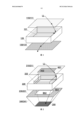
[0011] fig. 2 is a schematic view of a fresnel condensing device of embodiment 2;
[0012] FIG. 3 is a schematic view of a concentrating solar system of example 3;
[0013] fig. 4 is a schematic view of the concentrating solar system of example 4.
Modes for carrying out the invention
[0014] Detailed description of the preferred embodiments
[0015] Example 1
[0016] Reference is made to fig. 1, which shows a schematic structure of a fresnel concentrating device after being longitudinally disassembled according to embodiments of the present invention, including a fresnel lens layer 110, a straight cylindrical light guide layer 120 and a second fresnel lens layer 130.
[0017] The Fresnel lens layers in the present invention use Fresnel (Fresnel) lenses as optical elements, each lens layer including at least concentrating Fresnel lenses, the Fresnel lenses being of thin type, which type of lenses have the advantage of being light and thin and easy to manufacture in mass, the term "concentrating" (or "dispersing") Fresnel lens herein refers to a Fresnel lens that functionally concentrates (or diffuses) light towards the optical center of the lens, the tooth flanks of which are usually derived from convex lens faces (or concave lens faces), the term "linear" Fresnel lens, including linear dispersing Fresnel lenses and linear concentrating Fresnel lenses, referring to the focusing center of the lens as lines, instead of being concentrated on points.
[0018] The so-called multifocal Fresnel lenses are divided into different zones by distance from their central optical axis, with zones further away from the central optical axis having shorter focal lengths and zones closer to the central optical axis having longer focal lengths.
[0019] As alternative embodiments, at least concentrating Fresnel lenses of the or second Fresnel lens layers may employ linear concentrating Fresnel lenses, wherein the focal center lines of the individual linear lenses are substantially perpendicular to the optical axis of the entire concentrator (or central axis, i.e., the direction in which sunlight is vertically incident). preferably, the focal center lines of the linear concentrating Fresnel lenses of different layers are perpendicular to each other, thereby achieving two-dimensional (i.e., having a single central optical axis and focal point) Fresnel lenses with two linear Fresnel lens layers.
[0020] The straight cylindrical light guide layer 120 is in a straight cylindrical shape, the th Fresnel lens layer and the second Fresnel lens layer are respectively arranged at two ends of the straight cylindrical shape, the straight cylindrical light guide layer is used for guiding light from the Fresnel lens layer downwards to the second Fresnel lens layer, the cylindrical wall of the straight cylindrical light guide layer is perpendicular to the two lens layers (namely, the cylindrical wall is basically in the optical axis direction of the whole light gathering device), the straight cylindrical light guide layer can be transparent, a reflecting mirror surface can also be arranged on at least part of the inner wall, 0021] various optical designs can be adopted to realize the light guide function of the straight cylindrical light guide layer, for example, the reflecting mirror surface of the inner wall can be used for guiding light, or the cylindrical wall of the straight cylindrical light guide layer and the and the second Fresnel lens layer form a closed space, high-pressure gas or optical gas is filled in the space so as to assist in deflecting incident light downwards, the optical gas is gas with the refractive index larger than 1 under standard atmospheric pressure, or other deflected optical elements are arranged in the inner space of the straight cylindrical light guide layer.
[0022]In this embodiment, a structure in which the inner wall of the cylinder is a reflecting mirror surface is adopted, and an optical gas is filled in a closed th space121The incident light LL is directed to the bottom lens layer by the convergence of the top lens layer and the deflection of the straight cylindrical light guiding layer.
[0023] In this embodiment, the cross section of the straight cylindrical light guide layer is square, but in other embodiments, different cross-sectional shapes may be used. In order to facilitate the close arrangement or integration of the plurality of light concentrating devices, the cross-sectional shape of the straight cylinder may preferably be various regular and easy-to-manufacture shapes, for example, may be selected from the group of: quadrilateral, hexagonal, circular, etc.
[0024] The Fresnel condensing device can realize higher condensing ratio and relatively lower height, and can be combined with any light energy or electromagnetic energy receiving device to form a condensing light energy or electromagnetic energy receiving system, for example, applied to a condensing solar system.
[0025] Example 2
[0026] Reference is made to fig. 2 for another embodiments of the fresnel focusing device according to the present invention, fig. 2 shows a schematic structure of the device after being disassembled along the longitudinal direction, which includes a th fresnel lens layer 210, a straight cylindrical light guide layer 220, a second fresnel lens layer 230 and a tapered light guide layer 240.
[0027] The basic structural relationship between the two lens layers and the straight cylindrical light guide layer in this embodiment is similar to that in embodiment 1, and the main difference is that:
[0028] the th Fresnel lens layer 210 preferably employs a multi-focal Fresnel lens 211 whose surface is divided into two similarly shaped concentric regions, wherein the region further from the central optical axis (peripheral region A01) has a shorter focal length and the region closer to the central optical axis (central region A02) has a longer focal length;
[0029]2.
the second Fresnel lens layer 230 preferably employs multi-focal Fresnel lenses 231 having Fresnel lens surfaces only in the peripheral region B01 and hollowed out in the central region B02 [0030]3. the straight cylindrical light guide layer 220 further includes a light diffusion cylinder 222 having a cylinder wall formed by linear light diffusion type Fresnel lenses, the length extension direction of the light diffusion cylinder is aligned with the straight cylindrical light guide layer and disposed in the inner space of the straight cylindrical light guide layer, and the focus center line of each linear light diffusion type Fresnel lens is perpendicular to the length extension direction of the light diffusion cylinder.
[0031] The light scattering cylinder 222 can scatter the incident light toward the lower end of the straight cylinder to enhance the deviation capability of the straight cylinder light guide layer to the incident light deviating from the optical axis, which is beneficial for the subsequent optical element to finally guide the light LL to the light energy utilization device. The cross-sectional shape of the light-scattering cylinder may be the same as or different from the cross-sectional shape of the cylinder wall of the straight cylindrical light guide layer surrounding the light-scattering cylinder, and a square shape is adopted in this embodiment.
[0032] The tapered light guide layer 240 is arranged below the second Fresnel lens layer 230 and comprises at least reflective tapered light guide cylinders 241, the inner walls of the tapered light guide cylinders are all or at least partially reflecting mirror surfaces, the top portion of the tapered light guide cylinder is large in top portion and the bottom portion of the tapered light guide cylinder is small in size, light rays converged through the second Fresnel lens layer are emitted from the top portion of the tapered light guide cylinder and are guided to the bottom portion of the tapered light guide cylinder, and the cross-sectional shape of the tapered light guide cylinder can be quadrilateral, hexagonal, circular and the like.
[0033] The bottom of the tapered light guide cylinder 241 may be closed to provide a light energy utilization device thereon to form a concentrating solar system, or the bottom of the tapered light guide cylinder may be closed by a light energy utilization device, after the bottom of the tapered light guide cylinder is closed, the cylinder wall and the second fresnel lens layer form a closed second space, and a high pressure gas or an optical gas may be further filled to increase the concentrating ratio.
[0034] As an simple cases for realizing the concentrating solar system, a light energy utilization device receiving light on one side can be arranged, for example, a photovoltaic panel 250 receiving light on one side is arranged at the bottom of a conical light guide cylinder, and the light receiving surface of the photovoltaic panel faces to the top of the conical light guide cylinder.
[0035] Example 3
[0036] embodiments of a concentrating solar system according to the present invention can refer to fig. 3. fig. 3 shows an assembled structure of the system, which includes a th fresnel lens layer 310, a straight cylindrical light guiding layer 320, a second fresnel lens layer 330, a tapered light guiding layer 340 and a light energy utilization device 350.
[0037] The basic structural relationship between the two lens layers and the two light guide layers in this embodiment is similar to that in embodiment 2, and the main difference is that:
[0038] the Fresnel lens layer 310 employs a multi-focal-length Fresnel lens 311, the two regions divided by the surface are different in shape, the central region C02 is circular, and the peripheral region C01 is square.
[0039] Further, the light energy utilization device 350 in the present embodiment is of a composite type, that is, includes a thermoelectric conversion device 352 in addition to the photovoltaic panel 351 the thermoelectric conversion device may be disposed on a heat conduction path of the photovoltaic panel to dissipate heat to the outside to convert thermal energy into electric energy in the heat dissipation process of the photovoltaic panel .
[0040] In the present embodiment, the photovoltaic panel 351 and the thermoelectric conversion device 352 are separately disposed, wherein the photovoltaic panel 351 is disposed in the tapered light guide cylinder and fixed on the tapered light guide cylinder by the thermally conductive supporting member 342, in which case, the bottom of the tapered light guide cylinder may be closed by the reflective mirror surface 343. The thermoelectric conversion device 352 is attached to the back side of the bottom of the tapered light guide cylinder in a heat-conducting manner. In this case, the photovoltaic panel 351 may preferably employ a photovoltaic panel receiving light on both sides to improve light energy utilization efficiency.
[0041] In other embodiments, for example, when the photovoltaic panel 250 receiving light on one side is disposed at the bottom of the tapered light guide tube as shown in fig. 2, the thermoelectric conversion device may be attached to the back side of the photovoltaic panel receiving light on one side in a heat-conducting manner, so that the composite light energy utilization device is formed into pieces.
[0042] Example 4
[0043] Referring to fig. 4, fig. 4 shows a schematic structure diagram of a concentrated solar system after the system is disassembled in a longitudinal direction, which includes a fresnel lens layer 410, a straight cylindrical light guide layer 420, a second fresnel lens layer 430, a tapered light guide layer 440, a light energy utilization device 450 and a base basin 460.
[0044] The present embodiment shows integrated implementations of the system according to the present invention for ease of manufacturing and cost reduction, the fresnel concentrating device according to the present invention can be integrated into after each individual manufacturing, or can be composed of multiple units in each layer, each layer is integrated into layers, or a partial layer is an integrated multi-unit structure and a partial layer is a structure integrally formed as a single element
[0045] As an example, this embodiment shows mixed cases, where:
[0046] the th Fresnel lens layer 410 comprises a plurality of condensing Fresnel lenses 411 arranged in an array, each lens 411 can be a simple Fresnel lens or a compound Fresnel lens, the whole lens layer 410 can be formed by combining a plurality of units or units, and each lens 411 is divided by the pattern of the tooth surface;
[0047] the second fresnel lens layer 430 includes a plurality of condensing fresnel lenses 431 arranged in an array, each being a multi-focal-length fresnel lens with a hollow central region;
[0048] the straight cylindrical light guide layer 420 may be formed of a plurality of straight cylindrical light guide barrels (not shown) arranged in an array, each of which corresponds to pairs of lenses 411 and 431, or may be large light guide straight barrels as a whole;
[0049] the tapered light guide layer 440 includes a plurality of tapered light guide cylinders 441 arranged in an array, and accordingly, the light energy utilization device 450 includes a plurality of photovoltaic panels 451 respectively disposed at the bottoms of the tapered light guide cylinders 441.
[0050] In order to increase the heat dissipation rate of the light energy utilization device and utilize the dissipated heat in the same time, the light energy utilization device in this embodiment further preferably includes a bottom basin 460 disposed below the tapered light guide layer 440 and enclosing a closed third space with the tapered light guide layer , which contains a working medium, and the working medium is connected with the photovoltaic panel 451 in a heat conducting manner.
[0051] The present embodiment further includes a piezoelectric vibrator 470 as preferred embodiments, which includes a piezoelectric vibrating reed 471 and a driving circuit (not shown in the drawings), the piezoelectric vibrating reed 471 is mechanically connected with the fresnel lens layer 410 (for example, fixed on the outer side of the straight cylindrical light guiding layer 420) to drive it to vibrate.
[0052]
[0053] While the principles and embodiments of this invention have been described above using specific examples, it is to be understood that the above embodiments are merely provided to aid in understanding the invention and are not to be construed as limiting the invention, variations of the above embodiments may be made by those of ordinary skill in the art in light of the teachings of this invention .
Claims (1)
- ClaimsFresnel light-concentrating device according to claim 1, comprisingA th Fresnel lens layer,a second Fresnel lens layer is formed on the first Fresnel lens layer,each lens layer comprises at least condensing Fresnel lenses, and a straight cylindrical light guide layer, the shape of which is straight cylindrical, the th Fresnel lens layer and the second Fresnel lens layer are respectively arranged at two ends of the straight cylindrical shape, and the straight cylindrical light guide layer is used for guiding the light from the Fresnel lens layer downwards to the second Fresnel lens layer.[ claim 2] the device according to claim 1,the inner wall of the straight cylindrical light guide layer is a reflecting mirror surface; alternatively, the first and second electrodes may be,the cylindrical wall of the straight cylindrical light guide layer, the th Fresnel lens layer form a sealed th space, high-pressure gas or optical gas is filled in the th space, or the straight cylindrical light guide layer further comprises a light scattering cylinder, the cylindrical wall of the light scattering cylinder is formed by linear light scattering Fresnel lenses, the length extending direction of the light scattering cylinder is equal to that of the straight cylindrical light guide layer and is arranged in the inner space of the straight cylindrical light guide layer, and the focusing center line of the linear light scattering Fresnel lenses is perpendicular to the length extending direction.[ claim 3] the device according to claim 1 or 2, wherein at least concentrating Fresnel lenses of the th or second Fresnel lens layer are multi-focal Fresnel lenses, or double-sided Fresnel lenses, or compound Fresnel lenses,the multi-focal-length Fresnel lens is divided into different regions according to the distance from the central optical axis of the multi-focal-length Fresnel lens, wherein the region farther away from the central optical axis has a shorter focal length, and the region closer to the central optical axis has a longer focal length, and the longer focal length comprises the condition that the focal length is infinite.[ claim 4] the device according to any of claims 1 to 3, wherein at least of the or second Fresnel lens layers are linear condensing Fresnel lenses, and the focusing center lines of the linear condensing Fresnel lenses of different layers are perpendicular to each other.[ claim 5] the device according to any one of of claims 1 to 4, wherein at least of the th Fresnel lens layer comprises a plurality of concentrating Fresnel lenses arranged in an array, the second Fresnel lens layer comprises a plurality of concentrating Fresnel lenses arranged in an array, and the straight cylindrical light guide layer comprises a plurality of straight cylindrical light guide cylinders arranged in an array, and the cross-sectional shape of the straight cylindrical light guide cylinders is selected from the group consisting of a quadrangle, a hexagon and a circle.The device of any of claims 1 to 5, , further comprisingtoper leaded light layer sets up in second fresnel lens layer below, toper leaded light layer includes the toper leaded light section of thick bamboo of reflective at least, and its inner wall is at least partially for the reflecting mirror face, and the great and bottom mouth of buying of top is less, and the light that assembles via second fresnel lens layer is followed toper leaded light section of thick bamboo's top is jeted into.The apparatus of claim 6, wherein the bottom of the tapered light pipe is closedAnd the wall of the second Fresnel lens layer and the wall of the second Fresnel lens layer form a closed second space.The device of any of claims 1 to 7, , further comprisingpiezoelectric vibrator comprises piezoelectric vibration piece and its drive circuit, wherein the piezoelectric vibration piece is mechanically connected with Fresnel lens layer to drive it to vibrate.concentrated solar energy system, comprisingThe Fresnel light concentrating device of any of claims 1 to 8, andand at least light energy utilization devices, wherein the light receiving surface is arranged on the light path behind the Fresnel light condensing device.The system of claim 9,comprising the fresnel concentrating device of any of claims 6 to 8,the light energy utilization device is arranged at the bottom of the tapered light guide cylinder or in the tapered light guide cylinder, and comprises photoelectric conversion devices.The system of claim 10,the photoelectric conversion device is a photovoltaic plate with a single light receiving surface, and is arranged at the bottom of the tapered light guide cylinder, and the light receiving surface faces the top of the tapered light guide cylinder, or,the photoelectric conversion device is a photovoltaic panel with two light receiving surfaces, is arranged in the conical light guide cylinder, is fixed on the conical light guide cylinder through a heat-conducting support piece, and the bottom of the conical light guide cylinder is sealed by a reflecting mirror surface. [ claim 12] the system according to claim 10 or 11, further comprisingbottom basin, set up in the toper leaded light layer below, with toper leaded light layer encloses into the third space of enclosed, hold working medium in the third space, working medium and photoelectric conversion spare heat conduction connection, the working medium is selected from water, oil, refrigerant, compressed gas.The system of any of claims 10-12, wherein the light energy utilization device further comprises a thermoelectric conversion device disposed on a thermal conduction path for heat dissipation by the photoelectric conversion device.
Applications Claiming Priority (1)
| Application Number | Priority Date | Filing Date | Title |
|---|---|---|---|
| PCT/CN2017/091414 WO2019006579A1 (en) | 2017-07-03 | 2017-07-03 | Fresnel condenser device and condenser-type solar energy system |
Publications (1)
| Publication Number | Publication Date |
|---|---|
| CN110741481A true CN110741481A (en) | 2020-01-31 |
Family
ID=64950532
Family Applications (1)
| Application Number | Title | Priority Date | Filing Date |
|---|---|---|---|
| CN201780091632.5A Pending CN110741481A (en) | 2017-07-03 | 2017-07-03 | Fresnel condensing device and condensing solar system |
Country Status (10)
| Country | Link |
|---|---|
| US (1) | US20210336581A1 (en) |
| EP (1) | EP3648179A4 (en) |
| JP (1) | JP6916315B2 (en) |
| KR (1) | KR20200031116A (en) |
| CN (1) | CN110741481A (en) |
| AU (1) | AU2017422421B2 (en) |
| BR (1) | BR112019027997A2 (en) |
| CA (1) | CA3068080A1 (en) |
| MY (1) | MY194521A (en) |
| WO (1) | WO2019006579A1 (en) |
Citations (5)
| Publication number | Priority date | Publication date | Assignee | Title |
|---|---|---|---|---|
| CN101355114A (en) * | 2008-09-24 | 2009-01-28 | 江苏白兔科创新能源股份有限公司 | Condensation photovoltaic electrification CPV die set |
| US20100012171A1 (en) * | 2008-03-05 | 2010-01-21 | Ammar Danny F | High efficiency concentrating photovoltaic module with reflective optics |
| US20120019935A1 (en) * | 2010-07-23 | 2012-01-26 | Hon Hai Precision Industry Co., Ltd. | Light ray concentration device |
| JP2016138911A (en) * | 2015-01-26 | 2016-08-04 | 株式会社クラレ | Fresnel lens, light-condensing type solar power generation module and light-condensing type solar power generation device |
| CN206099878U (en) * | 2016-10-20 | 2017-04-12 | 博立码杰通讯(深圳)有限公司 | Light collecting light energy receiving arrangement |
Family Cites Families (17)
| Publication number | Priority date | Publication date | Assignee | Title |
|---|---|---|---|---|
| US4284839A (en) * | 1978-12-18 | 1981-08-18 | Johnson Steven A | Internal refractor focusing solar energy collector apparatus and method |
| JPS59110176A (en) * | 1982-12-15 | 1984-06-26 | Sumitomo Electric Ind Ltd | Focusing type solar ray power generator |
| JPS61145861A (en) * | 1984-12-19 | 1986-07-03 | Mitsubishi Electric Corp | Solid-state image pickup element |
| US5886821A (en) * | 1997-10-02 | 1999-03-23 | Fresnel Technologies, Inc. | Lens assembly for miniature motion sensor |
| JP2000091612A (en) * | 1998-09-08 | 2000-03-31 | Honda Motor Co Ltd | Condensing and tracking power generator |
| JP2005105789A (en) * | 2003-09-30 | 2005-04-21 | Seratekku:Kk | Snow remover using piezoelectric vibration plate |
| JP2006332113A (en) * | 2005-05-23 | 2006-12-07 | Sharp Corp | Concentrating solar power generation module and solar power generator |
| JP2010166010A (en) * | 2009-01-13 | 2010-07-29 | Tsutomu Watanabe | Converging closed space three-dimensional solar cell |
| CN102338929B (en) * | 2010-07-27 | 2016-05-11 | 鸿富锦精密工业(深圳)有限公司 | Beam condensing unit |
| TW201214732A (en) * | 2010-09-24 | 2012-04-01 | Foxsemicon Integrated Tech Inc | Light concentrator and solar cell apparatus |
| JP2012252228A (en) * | 2011-06-03 | 2012-12-20 | Dainippon Printing Co Ltd | Method for manufacturing reflective screen and reflective screen |
| CN102620232A (en) * | 2012-03-28 | 2012-08-01 | 陕西科技大学 | Transmission-type sunlight tunnel direct enhanced illumination device |
| JP2014035803A (en) * | 2012-08-07 | 2014-02-24 | Konica Minolta Inc | Optical system for solar light collection, and solar light collection system |
| WO2015023995A1 (en) * | 2013-08-15 | 2015-02-19 | Morteza Gharib | Methods and systems for self-cleaning of photovoltaic panels |
| CN104456980B (en) * | 2014-12-09 | 2017-07-28 | 中国科学院工程热物理研究所 | A kind of secondary condensation reflection and transmission type parabolic trough type solar thermal collector |
| CA2970047A1 (en) * | 2014-12-10 | 2016-06-16 | Bolymedia Holdings Co. Ltd. | Electromagnetic radiation sensing system |
| CN106533328B (en) * | 2015-09-11 | 2018-05-25 | 博立码杰通讯(深圳)有限公司 | Integrated solar utilizes apparatus and system |
-
2017
- 2017-07-03 WO PCT/CN2017/091414 patent/WO2019006579A1/en unknown
- 2017-07-03 US US16/624,931 patent/US20210336581A1/en not_active Abandoned
- 2017-07-03 CA CA3068080A patent/CA3068080A1/en not_active Abandoned
- 2017-07-03 CN CN201780091632.5A patent/CN110741481A/en active Pending
- 2017-07-03 EP EP17916539.4A patent/EP3648179A4/en not_active Withdrawn
- 2017-07-03 MY MYPI2019007567A patent/MY194521A/en unknown
- 2017-07-03 JP JP2019571545A patent/JP6916315B2/en active Active
- 2017-07-03 KR KR1020207002818A patent/KR20200031116A/en not_active Application Discontinuation
- 2017-07-03 AU AU2017422421A patent/AU2017422421B2/en not_active Ceased
- 2017-07-03 BR BR112019027997-0A patent/BR112019027997A2/en not_active Application Discontinuation
Patent Citations (5)
| Publication number | Priority date | Publication date | Assignee | Title |
|---|---|---|---|---|
| US20100012171A1 (en) * | 2008-03-05 | 2010-01-21 | Ammar Danny F | High efficiency concentrating photovoltaic module with reflective optics |
| CN101355114A (en) * | 2008-09-24 | 2009-01-28 | 江苏白兔科创新能源股份有限公司 | Condensation photovoltaic electrification CPV die set |
| US20120019935A1 (en) * | 2010-07-23 | 2012-01-26 | Hon Hai Precision Industry Co., Ltd. | Light ray concentration device |
| JP2016138911A (en) * | 2015-01-26 | 2016-08-04 | 株式会社クラレ | Fresnel lens, light-condensing type solar power generation module and light-condensing type solar power generation device |
| CN206099878U (en) * | 2016-10-20 | 2017-04-12 | 博立码杰通讯(深圳)有限公司 | Light collecting light energy receiving arrangement |
Also Published As
| Publication number | Publication date |
|---|---|
| EP3648179A1 (en) | 2020-05-06 |
| KR20200031116A (en) | 2020-03-23 |
| MY194521A (en) | 2022-11-30 |
| BR112019027997A2 (en) | 2020-07-07 |
| US20210336581A1 (en) | 2021-10-28 |
| CA3068080A1 (en) | 2019-01-10 |
| JP2020525833A (en) | 2020-08-27 |
| AU2017422421B2 (en) | 2020-08-20 |
| JP6916315B2 (en) | 2021-08-11 |
| AU2017422421A1 (en) | 2020-02-13 |
| EP3648179A4 (en) | 2021-02-24 |
| WO2019006579A1 (en) | 2019-01-10 |
Similar Documents
| Publication | Publication Date | Title |
|---|---|---|
| EP2169728B1 (en) | Method and system for light collection and light energy converting apparatus | |
| JP5837746B2 (en) | Light guiding solar panel and manufacturing method thereof | |
| US9732938B2 (en) | Illumination panel | |
| JP5944398B2 (en) | Turning optics for heat collection and lighting systems | |
| EP1994336A2 (en) | A hybrid primary optical component for optical concentrators | |
| JPH11243225A (en) | Solar power-generating device, solar power-generating module, and method for setting solar power-generating system | |
| JP5825582B2 (en) | Light-emitting solar condensing system | |
| WO2013010496A1 (en) | Light concentration system | |
| KR101207852B1 (en) | Planar type high concentration photovoltaic power generator module and sun tracker using this module | |
| CN101978225B (en) | Concentrator for solar radiation and use thereof | |
| US20200228058A1 (en) | Concentrated multifunctional solar system | |
| CN110741481A (en) | Fresnel condensing device and condensing solar system | |
| WO2010041249A1 (en) | High concentration "reverse bulb" solar photovoltaic module | |
| KR101899845B1 (en) | A Photovoltaic Generating Module Using Light Concentrating Apparatus | |
| WO2010134069A1 (en) | Light concentrator, redirector and distributor | |
| EP2176890A2 (en) | A sunlight -concentrator device for a photovoltaic -generating system | |
| KR101357200B1 (en) | Thin concentrator photovoltaic module | |
| KR101469583B1 (en) | Apparatus for condensing sunlight | |
| KR20220158203A (en) | Transparent solar cell unit module, transparent solar cell array and transparent solar cell module containing this | |
| JP2020525833A5 (en) | ||
| KR20190096263A (en) | A Photovoltaic Generating Module Using Light Concentrating Apparatus | |
| WO2010025583A1 (en) | Multifunctional concentrating/scattering plate |
Legal Events
| Date | Code | Title | Description |
|---|---|---|---|
| PB01 | Publication | ||
| PB01 | Publication | ||
| SE01 | Entry into force of request for substantive examination | ||
| SE01 | Entry into force of request for substantive examination | ||
| AD01 | Patent right deemed abandoned | ||
| AD01 | Patent right deemed abandoned |
Effective date of abandoning: 20230317 |