KR20190096263A - A Photovoltaic Generating Module Using Light Concentrating Apparatus - Google Patents
A Photovoltaic Generating Module Using Light Concentrating Apparatus Download PDFInfo
- Publication number
- KR20190096263A KR20190096263A KR1020180069796A KR20180069796A KR20190096263A KR 20190096263 A KR20190096263 A KR 20190096263A KR 1020180069796 A KR1020180069796 A KR 1020180069796A KR 20180069796 A KR20180069796 A KR 20180069796A KR 20190096263 A KR20190096263 A KR 20190096263A
- Authority
- KR
- South Korea
- Prior art keywords
- reflecting surface
- solar cell
- solar
- reflecting
- reflection
- Prior art date
- Legal status (The legal status is an assumption and is not a legal conclusion. Google has not performed a legal analysis and makes no representation as to the accuracy of the status listed.)
- Withdrawn
Links
- 230000003287 optical effect Effects 0.000 claims description 31
- 239000012530 fluid Substances 0.000 claims description 16
- 238000000034 method Methods 0.000 claims description 11
- XAGFODPZIPBFFR-UHFFFAOYSA-N aluminium Chemical compound [Al] XAGFODPZIPBFFR-UHFFFAOYSA-N 0.000 claims description 6
- 229910052782 aluminium Inorganic materials 0.000 claims description 6
- 229920005989 resin Polymers 0.000 claims description 4
- 239000011347 resin Substances 0.000 claims description 4
- 238000009833 condensation Methods 0.000 abstract description 3
- 230000005494 condensation Effects 0.000 abstract description 3
- 238000010248 power generation Methods 0.000 description 13
- 230000000694 effects Effects 0.000 description 6
- 238000004519 manufacturing process Methods 0.000 description 6
- 229920003002 synthetic resin Polymers 0.000 description 6
- 239000000057 synthetic resin Substances 0.000 description 6
- 239000000853 adhesive Substances 0.000 description 4
- 230000001070 adhesive effect Effects 0.000 description 4
- 239000000463 material Substances 0.000 description 4
- 239000000758 substrate Substances 0.000 description 4
- 239000004820 Pressure-sensitive adhesive Substances 0.000 description 3
- 238000000465 moulding Methods 0.000 description 3
- 238000006243 chemical reaction Methods 0.000 description 2
- 238000000151 deposition Methods 0.000 description 2
- 238000001746 injection moulding Methods 0.000 description 2
- 238000012986 modification Methods 0.000 description 2
- 230000004048 modification Effects 0.000 description 2
- 238000002834 transmittance Methods 0.000 description 2
- NIXOWILDQLNWCW-UHFFFAOYSA-N acrylic acid group Chemical group C(C=C)(=O)O NIXOWILDQLNWCW-UHFFFAOYSA-N 0.000 description 1
- 238000001816 cooling Methods 0.000 description 1
- 238000010586 diagram Methods 0.000 description 1
- 230000008034 disappearance Effects 0.000 description 1
- 230000005611 electricity Effects 0.000 description 1
- 238000001125 extrusion Methods 0.000 description 1
- 238000009434 installation Methods 0.000 description 1
- 230000001678 irradiating effect Effects 0.000 description 1
- 238000011084 recovery Methods 0.000 description 1
- 238000001028 reflection method Methods 0.000 description 1
Images





Classifications
-
- H—ELECTRICITY
- H02—GENERATION; CONVERSION OR DISTRIBUTION OF ELECTRIC POWER
- H02S—GENERATION OF ELECTRIC POWER BY CONVERSION OF INFRARED RADIATION, VISIBLE LIGHT OR ULTRAVIOLET LIGHT, e.g. USING PHOTOVOLTAIC [PV] MODULES
- H02S40/00—Components or accessories in combination with PV modules, not provided for in groups H02S10/00 - H02S30/00
- H02S40/20—Optical components
- H02S40/22—Light-reflecting or light-concentrating means
-
- G—PHYSICS
- G02—OPTICS
- G02B—OPTICAL ELEMENTS, SYSTEMS OR APPARATUS
- G02B5/00—Optical elements other than lenses
- G02B5/08—Mirrors
- G02B5/09—Multifaceted or polygonal mirrors, e.g. polygonal scanning mirrors; Fresnel mirrors
-
- H01L31/042—
-
- H—ELECTRICITY
- H02—GENERATION; CONVERSION OR DISTRIBUTION OF ELECTRIC POWER
- H02S—GENERATION OF ELECTRIC POWER BY CONVERSION OF INFRARED RADIATION, VISIBLE LIGHT OR ULTRAVIOLET LIGHT, e.g. USING PHOTOVOLTAIC [PV] MODULES
- H02S30/00—Structural details of PV modules other than those related to light conversion
-
- H—ELECTRICITY
- H10—SEMICONDUCTOR DEVICES; ELECTRIC SOLID-STATE DEVICES NOT OTHERWISE PROVIDED FOR
- H10F—INORGANIC SEMICONDUCTOR DEVICES SENSITIVE TO INFRARED RADIATION, LIGHT, ELECTROMAGNETIC RADIATION OF SHORTER WAVELENGTH OR CORPUSCULAR RADIATION
- H10F19/00—Integrated devices, or assemblies of multiple devices, comprising at least one photovoltaic cell covered by group H10F10/00, e.g. photovoltaic modules
-
- Y—GENERAL TAGGING OF NEW TECHNOLOGICAL DEVELOPMENTS; GENERAL TAGGING OF CROSS-SECTIONAL TECHNOLOGIES SPANNING OVER SEVERAL SECTIONS OF THE IPC; TECHNICAL SUBJECTS COVERED BY FORMER USPC CROSS-REFERENCE ART COLLECTIONS [XRACs] AND DIGESTS
- Y02—TECHNOLOGIES OR APPLICATIONS FOR MITIGATION OR ADAPTATION AGAINST CLIMATE CHANGE
- Y02E—REDUCTION OF GREENHOUSE GAS [GHG] EMISSIONS, RELATED TO ENERGY GENERATION, TRANSMISSION OR DISTRIBUTION
- Y02E10/00—Energy generation through renewable energy sources
- Y02E10/50—Photovoltaic [PV] energy
- Y02E10/52—PV systems with concentrators
Landscapes
- Physics & Mathematics (AREA)
- General Physics & Mathematics (AREA)
- Optics & Photonics (AREA)
- Photovoltaic Devices (AREA)
Abstract
태양광의 입사 방향에 대해 거의 수직을 이루지만 약간의 각도(a)로 기울어진 반사 플레이트(20)를 설치하고, 상기 반사 플레이트(20)의 측면에서 상기 태양광의 입사 방향에 대해서는 거의 평행하면서 상기 반사 플레이트(20)의 표면을 바라보는 방향으로 태양광 조사 표면을 정렬하여 솔라셀(10)을 설치함으로써, 태양광의 집광 전 조사 면적(A1) 대비 태양광의 집광 후 입사 면적(A2)를 크게 줄일 수 있고, 솔라셀(10)의 면적을 태양광 조사 면적 대비 tan a 만큼 줄이며, 전체적인 태양광 발전 모듈의 크기(L * w)도 크게 줄일 수 있는 태양광 발전 모듈을 제공한다.
반사 플레이트(20)는 태양광의 입사 방향으로 배치되는 제1반사면(21)과, 솔라셀(10)의 조사 표면을 바라보는 제2반사면(22)이 이웃하는 반사면 유닛(23)들이 나란히 배열된 형태를 가지므로, 매우 좁은 공간 내에서도 태양광을 일측 방향으로 수평 광 형태로 집광하는 것이 가능하다.The reflection plate 20 which is substantially perpendicular to the direction of incidence of sunlight but is inclined at a slight angle a is provided, and the reflection is substantially parallel to the direction of incidence of the sunlight on the side of the reflection plate 20. By arranging the solar cells 10 by aligning the solar irradiation surface in a direction facing the surface of the plate 20, the incident area A2 can be greatly reduced after condensing sunlight with respect to the irradiation area A1 before the condensation of sunlight. In addition, it reduces the area of the solar cell 10 by tan a compared to the solar irradiation area, and provides a photovoltaic module that can greatly reduce the size (L * w) of the overall photovoltaic module.
The reflecting plate 20 includes reflecting surface units 23 adjacent to the first reflecting surface 21 disposed in the direction of incidence of sunlight and the second reflecting surface 22 facing the irradiation surface of the solar cell 10. Since the shape is arranged side by side, it is possible to focus the sunlight in a horizontal light form in one direction even in a very narrow space.
Description
본 발명은 솔라셀의 면적을 최소화할 수 있고, 동시에 집광 모듈 역시 최소화할 수 있어, 전체적인 크기를 줄인 컴팩트형 집광식 태양광 발전 모듈에 관한 것이다.The present invention can minimize the area of the solar cell, and at the same time can also minimize the light concentrating module, and relates to a compact condensed photovoltaic module with reduced overall size.
에너지의 효율적인 사용에 대한 수요가 높아지면서, 태양광을 이용한 발전 설비에 대한 연구가 활발히 진행되고 있다. 처음에는 태양광을 전기로 변환시키는 솔라셀의 효율에 관한 연구가 활발히 진행되어 왔다.As the demand for efficient use of energy increases, research on power generation facilities using solar energy is being actively conducted. At first, research into the efficiency of solar cells that convert sunlight into electricity has been actively conducted.
그러나 솔라셀의 전기에너지 변환 효율이 높아진다 하더라도 태양광 자체가 약하면 솔라셀의 변환 효율이 높다는 의미가 퇴색된다. 아울러 솔라셀의 가격은 그 면적과 비례하는바, 보다 좁은 면적의 솔라셀을 사용하여 보다 많은 전기에너지를 생산하는 것이 더욱 효율적이다.However, even if solar cell's electrical energy conversion efficiency is increased, the weak solar light itself means that the conversion efficiency of the solar cell is high. In addition, the price of the solar cell is proportional to its area, so it is more efficient to produce more electric energy using a narrower cell.
이에 태양광을 집광하여 솔라셀에 조사함으로써 솔라셀의 면적 자체를 줄인 다양한 태양광 발전 모듈이 개발되고 있다. 가령 광학 렌즈를 통한 굴절 방식이나, 반사접시를 통한 반사 방식이 그것이다.Therefore, various solar power modules that reduce solar cell area by concentrating solar light and irradiating the solar cell have been developed. For example, it is a refractive method through an optical lens or a reflection method through a reflecting plate.
그러나 이러한 설비들은 모두, 빛의 반사나 굴절을 일으키는 집광설비와, 집광된 빛이 조사되는 솔라셀 간에 일정한 거리가 요구되고, 이는 전체적인 태양광 발전 모듈의 크기를 크게 증가시키는 원인이 된다. 따라서 태양광 발전 모듈을 설치할 수 있는 공간 자체의 제약으로 인해, 이를 사용할 수 있는 환경은 매우 제한적이다.However, all of these facilities require a certain distance between the light collecting facility causing the reflection or refraction of light and the solar cell to which the collected light is irradiated, which causes a large increase in the size of the entire photovoltaic module. Therefore, due to the limitations of the space in which the photovoltaic module can be installed, the environment in which it can be used is very limited.
아울러, 종래의 설비들은 집광 포인트가 복수 개 구비되므로, 작은 솔라셀을 복수 개 띄엄띄엄 별도로 설치해야 하는 번거로움이 있고, 이들 복수 개의 솔라셀을 각각 냉각해야 하는 번거로움이 있으며, 집광 각도가 조금만 틀어지더라도 집광된 태양광이 솔라셀의 조사 표면을 벗어나버린다는 문제가 있었다.In addition, since the conventional facilities are provided with a plurality of condensing points, there is a hassle to install a plurality of small solar cells separately, there is a hassle to cool each of the plurality of solar cells, and the light collecting angle is only a little There was a problem that the concentrated solar light would deviate from the solar cell's irradiation surface even if it was turned off.
태양광 발전 모듈은 넓은 면적을 가지고 있어 바람에 휘청거리는 현상이 발생하는데, 이는 종래의 태양광 집광 장치의 초점을 흔드는 원인이 되는바, 종래의 태양광 발전 모듈의 효율은 바람에 매우 민감하다는 문제가 있다.The solar power module has a large area, causing wind sway, which causes the focus of the conventional solar light collecting device. The efficiency of the conventional solar power module is very sensitive to the wind. There is.
본 발명은 상술한 문제점을 해결하기 위해 안출된 것으로, 솔라셀의 면적을 최소화하고, 아울러 집광장치와 솔라셀이 결합된 태양광 발전 모듈의 전체적인 크기가 컴팩트한 집광형 태양광 발전 모듈을 제공하는 것을 목적으로 한다.The present invention has been made to solve the above-described problems, to minimize the area of the solar cell, and to provide a light-converging solar power generation module of a compact solar cell module combined with the light collecting device and the solar cell in the overall size. For the purpose of
또한 본 발명은 제조가 간편하고 저렴하게 제작할 수 있는 집광형 태양광 발전 모듈을 제공하는 것을 목적으로 한다.In addition, an object of the present invention is to provide a light collecting solar power module that can be manufactured easily and inexpensively.
상술한 과제를 해결하기 위해 본 발명은, 태양광의 입사 방향에 대해 거의 수직을 이루지만 약간의 각도(a)로 기울어진 반사 플레이트(20)를 설치하고, 상기 반사 플레이트(20)의 측면에서 상기 태양광의 입사 방향에 대해서는 거의 평행하면서 상기 반사 플레이트(20)의 표면을 바라보는 방향으로 태양광 조사 표면을 정렬하여 솔라셀(10)을 설치함으로써, 태양광의 집광 전 조사 면적(A1) 대비 태양광의 집광 후 입사 면적(A2)를 크게 줄일 수 있고, 솔라셀(10)의 면적을 태양광 조사 면적 대비 tan a 만큼 줄이며, 전체적인 태양광 발전 모듈의 크기(L * w)도 크게 줄일 수 있는 태양광 발전 모듈을 제공한다.In order to solve the above-described problems, the present invention is provided with a
여기서, 상기 반사 플레이트(20)는, 제1반사면(21)은 상기 태양광의 입사 방향으로 배치되고, 상기 제1반사면과 이웃하는 제2반사면(22)은 상기 솔라셀(10)의 조사 표면을 바라보도록 배치되는 반사면 유닛(23)을 포함할 수 있다.Here, the
상기 반사면 유닛(23)은 단위 패턴을 이루고, 상기 반사 플레이트(20)는, 상기 단위 패턴을 포함하는 단위 형상물을 복수 개 배열하여 설치한 형태일 수 있다.The
이와 달리 반사 표면에 알루미늄을 증착한 UV 경화수지 필름 형태로 반사면 유닛(23)들이 일체화된 필름을 제작하여 반사 플레이트(20)를 구성하는 것도 가능하다.Alternatively, the
또한 상기 반사 플레이트(20)의 전면에 광학부재 또는 유체 매질을 설치하여, 반사 플레이트(20)에서 반사되어 상기 솔라셀(10)에 입사되는 집광 태양광 중 솔라셀(10)의 태양광 조사 표면에서 벗어나는 태양광이 전반사되도록 함으로써, 집광 효율을 더욱 높일 수 있다.In addition, by installing an optical member or a fluid medium on the front surface of the reflecting
상기 반사 플레이트(20)는 태양광의 입사 방향으로 배치되는 제1반사면(21)과, 솔라셀(10)의 조사 표면을 바라보는 제2반사면(22)이 이웃하는 반사면 유닛(23)들이 나란히 배열된 형태를 가지므로, 매우 좁은 공간 내에서도 태양광을 일측 방향으로 수평 광 형태로 집광하는 것이 가능하다.The reflecting
구체적으로 본 발명은, 태양광의 입사 방향에 대해, 태양광 조사 표면이 측면을 바라보도록 설치된 솔라셀(10); 및 제1반사면(21)은 상기 태양광의 입사 방향으로 배치되고, 상기 제1반사면과 이웃하는 제2반사면(22)은 상기 솔라셀(10)의 조사 표면을 바라보도록 배치되는 반사면 유닛(23)들이 복수 개 나란히 배열된 반사 플레이트(20);를 포함하고, 상기 반사면 유닛(23)의 제1반사면(21)은 입사된 태양광을, 상기 솔라셀로부터 멀어지는 방향으로, 그와 이웃하는 제2반사면(22)으로 반사시키고, 상기 제2반사면(22)은 상기 제1반사면(21)으로부터 반사된 태양광을 상기 솔라셀(10)의 태양광 조사 표면으로 반사시키는 것을 특징으로 하는 태양광 발전 모듈을 제공한다.Specifically, the present invention, the
상기 반사 플레이트(20)는, 서로 이웃하는 적어도 하나의 제1반사면(21)과 제2반사면(22)을 포함하는 단위패턴(25)을 포함할 수 있다.The
그리고, 상기 단위패턴(25)이 포함하는 제1반사면(21)과 제2반사면(22)은 각각 서로 이웃하는 두 반사면 유닛(23)의 제1반사면과 제2반사면일 수 있다.The first reflecting
상기 반사 플레이트(20)는 반사면 유닛(23)들이 표면에 성형된 필름일 수 있다.The
상기 필름은 UV 경화수지로 제작되고, 상기 반사면 유닛(23)의 표면에는 알루미늄이 증착될 수 있다. The film may be made of UV curable resin, and aluminum may be deposited on the surface of the
상기 태양광의 입사 방향에서 상기 반사 플레이트(20)를 바라보았을 때, 상기 제1반사면(21)이 노출되고, 상기 솔라셀(10)의 태양광 조사 표면에서 상기 반사 플레이트(20)를 바라보았을 때, 상기 제2반사면(22)이 노출될 수 있다.When looking at the reflecting
상기 반사 플레이트(20)는, 상기 솔라셀(10)의 태양광 조사 표면의 법선에 대해 소정 각도(a)만큼 기울어진 형태로 배치되고, 상기 소정 각도(a)는 45도 이하일 수 있다.The
상기 반사 플레이트(20)는, 상기 반사면 유닛(23)을 평행한 직선 형태로 복수 개 배열한 구조를 포함할 수 있다.The
상기 반사 플레이트(20)는, 상기 반사면 유닛(23)을 서로 다른 직경의 동심원 형태로 복수 개 배열한 구조를 포함할 수 있다.The
상기 솔라셀(10)의 폭(w)보다, 상기 솔라셀(10)의 태양광 조사 표면으로부터 상기 반사 플레이트(20)가 연장된 거리(L)가 더 길 수 있다.The distance L of the
상기 제1반사면(21)은 오목한 반사면의 프로파일을 가질 수 있다.The first
상기 제2반사면(22)은 볼록한 프로파일을 가질 수 있다.The second reflecting
상기 제2반사면(22)은 오목한 반사면의 프로파일을 가질 수 있다.The second reflecting
상기 태양광이 상기 제1반사면(21)에서 반사되는 제1반사광의 반사 각도(r1)와, 상기 제2반사면(22)에서 상기 제1반사면(21)의 제1반사광이 반사되는 제2반사광의 반사 각도(r2)의 합은 90도 또는 90도에 근접할 수 있다.The reflection angle r1 of the first reflection light reflected from the
상기 솔라셀(10)의 태양광 조사 표면과 상기 반사 플레이트(20)의 표면 사이의 공간에는 광학부재(30) 또는 유체 매질(26)이 채워지며 설치되고, 상기 광학부재(30) 또는 유체 매질(26)의 태양광 입사 표면은 상기 태양광의 입사 방향에 실질적으로 수직하게 배치될 수 있다.The space between the solar irradiation surface of the
상기 솔라셀(10)과 반사 플레이트(20)는 하우징(80)에 설치될 수 있다.The
상기 반사 플레이트(20)의 이면에 위치하는 하우징(80)에는 태양광 발전 모듈을 제어하는 기판(40)이 설치되는 수용부(84)가 마련될 수 있다.The
본 발명의 집광식 태양광 발전 모듈에 따르면, 넓은 면적으로 입사되는 평행한 태양광을, 반사 플레이트(20)를 통해 좁은 면적으로 반사 집광하므로, 솔라셀(10)의 태양광 조사 표면의 면적을 크게 줄일 수 있고, 반사 집광 태양광 역시 평행광이거나 평행광에 가까우므로, 태양광 발전 모듈의 넓은 면적으로 입사되는 태양광을, 좁은 면적을 가지는 하나의 솔라셀(10)에 집광할 수 있음은 물론, 솔라셀(10)을 반사 플레이트(20)에 매우 가깝게 배치할 수 있어, 종래의 반사 집광형 또는 굴절 집광형 태양광 발전 모듈과 대비하여 전체적으로 발전 모듈을 더욱 컴팩트하게 제작하는 것이 가능하다.According to the condensed photovoltaic module of the present invention, since parallel solar light incident on a large area is reflected and collected by a narrow area through the reflecting
또한 집광된 태양광이 조사되는 솔라셀(10)을 하나의 솔라셀(10)로 구성하면, 종래에 복수 개의 집광 포인트에 솔라셀을 분산 배치하던 구조에 비해, 집광된 태양광이 조사되는 각도가 다소 틀어지더라도 태양에너지의 손실이 거의 없고, 하나의 솔라셀을 냉각하면 되므로, 냉각 구조도 훨씬 간단하게 구현할 수 있고 열 회수에도 유리하다. In addition, when the
특히 본 발명과 같이 태양광 발전 모듈의 발전 효율이 태양광의 조사 각도에 둔감하면, 바람에 관계 없이 태양광 발전 모듈의 발전 효율을 더 높일 수 있다.In particular, when the power generation efficiency of the photovoltaic module is insensitive to the irradiation angle of sunlight, as in the present invention, it is possible to further increase the power generation efficiency of the photovoltaic module regardless of wind.
아울러 상기 반사 플레이트(20)의 제1반사면(21)과 제2반사면(22)의 프로파일은, 평행광으로 입사된 태양광을 집광하면서도 평행광으로 반사해낼 수 있기 때문에, 컴팩트함은 물론 구조가 매우 단순한 태양광 발전 모듈을 제작하는 것이 가능하게 해준다.In addition, since the profile of the first reflecting
또한 상기 반사 플레이트(20)를 필름 형태로 제작할 수 있으므로, 반사 플레이트(20)의 전체적인 프로파일을 다양하게 구현하는 것이 가능하다.In addition, since the
상술한 효과와 더불어 본 발명의 구체적인 효과는 이하 발명을 실시하기 위한 구체적인 사항을 설명하면서 함께 기술한다.In addition to the effects described above, the specific effects of the present invention will be described together with the following description of specifics for carrying out the invention.
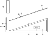
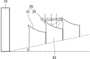
도 1은 본 발명에 따른 태양광 발전 모듈의 제1실시예의 분해 단면도이다.
도 2는 도 1의 태양광 발전 모듈의 단면도이다.
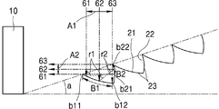
도 3은 도 2의 태양광 발전 모듈의 일 부분을 확대하여 나타낸 모식도이다.
도 4는 본 발명에 따른 태양광 발전 모듈의 제2실시예의 분해 단면도이다.
도 5는 도 4의 태양광 발전 모듈의 단면도이다.
도 6은 도 5의 태양광 발전 모듈의 일 부분을 확대하여 나타낸 모식도이다.
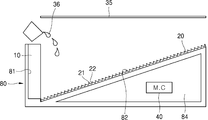
도 7은 본 발명에 따른 태양광 발전 모듈의 제3실시예의 분해 단면도이다.
도 8은 도 7의 태양광 발전 모듈의 단면도이다.
도 9는 본 발명에 따른 태양광 발전 모듈의 제4실시예를 부분적으로 확대하여 나타낸 모식도이다.도 10은 본 발명에 따른 태양광 발전 모듈의 제5실시예의 평면도이다.
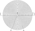
도 11은 본 발명에 따른 태양광 발전 모듈의 제6실시예의 평면도이다.
도 12는 본 발명에 따른 태양광 발전 모듈의 제7실시예의 단면도이다.1 is an exploded cross-sectional view of a first embodiment of a photovoltaic module according to the present invention.
FIG. 2 is a cross-sectional view of the solar power module of FIG. 1.
3 is an enlarged schematic view of a portion of the solar power module of FIG. 2.
4 is an exploded cross-sectional view of a second embodiment of a photovoltaic module according to the present invention.
5 is a cross-sectional view of the solar cell module of FIG. 4.
6 is an enlarged schematic view of a portion of the solar cell module of FIG. 5.
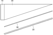
7 is an exploded cross-sectional view of a third embodiment of a photovoltaic module according to the present invention.
8 is a cross-sectional view of the solar cell module of FIG. 7.
9 is a schematic diagram showing a partially enlarged view of the fourth embodiment of the solar cell module according to the present invention. FIG. 10 is a plan view of a fifth embodiment of the solar cell module according to the present invention.
11 is a plan view of a sixth embodiment of a photovoltaic module according to the present invention.
12 is a cross-sectional view of a seventh embodiment of a photovoltaic module according to the present invention.
이하, 본 발명의 바람직한 실시예를 첨부한 도면을 참조로 하여 상세히 설명한다. Hereinafter, with reference to the accompanying drawings, preferred embodiments of the present invention will be described in detail.
본 발명은 이하에서 개시되는 실시예에 한정되는 것이 아니라 서로 다른 다양한 형태로 구현될 수 있으며, 단지 본 실시예는 본 발명의 개시가 완전하도록 하며 통상의 지식을 가진 자에게 발명의 범주를 완전하게 알려주기 위하여 제공되는 것이다.The present invention is not limited to the embodiments disclosed below, but can be implemented in various different forms, only this embodiment to make the disclosure of the present invention complete and to those skilled in the art to fully understand the scope of the invention It is provided to inform you.
[제1실시예][First Embodiment]
이하 도 1 내지 도 3을 참조하여 본 발명에 따른 태양광 발전 모듈의 제1실시예를 설명한다.Hereinafter, a first embodiment of a photovoltaic module according to the present invention will be described with reference to FIGS. 1 to 3.
태양광 발전 모듈은, 태양광을 전기에너지로 변환하는 솔라셀(10)과, 태양광을 집광하여 상기 솔라셀(10)에 반사하는 반사 플레이트(20)를 포함한다. 상기 솔라셀(10)과 반사 플레이트(20)는 하우징(80)에 설치되어 상호 상대적인 위치가 고정되며 조립될 수 있다.The photovoltaic module includes a
솔라셀(10)은 태양광을 흡수하는 조사 표면을 가진다. 본 발명에 따르면 태양광의 입사 방향에 대해, 상기 솔라셀(10)의 조사 표면이 나란히 배열되도록 설치된다. 즉 솔라셀(10)의 조사 표면은 입사되는 태양광을 직접 바라보지 않는다. 대신 상기 솔라셀(10)은, 그 조사 표면이, 입사되는 태양광을 집광 반사하는 반사 플레이트(20)의 표면을 바라보도록 설치된다.The
반사 플레이트(20)는 그 반사 표면이, 태양광의 입사 방향을 바라보고, 동시에 상기 솔라셀(10)의 조사 표면도 바라보도록 설치된다. 즉 반사 플레이트(20)의 반사 표면은, 상기 태양광의 입사 방향에 대해서도 비스듬히 배치되고, 상기 솔라셀(10)의 조사 표면에 대해서도 비스듬히 배치되는 경사면의 형태로 배치된다. The
상기 하우징(80)은 상기 솔라셀(10)이 설치되는 솔라셀 설치부(81)와, 상기 반사 플레이트(20)가 설치되는 반사플레이트 설치면(82)을 포함한다. 그리고 상기 반사플레이트 설치면(82)의 이면에 마련되는 대략 직각삼각형 형태의 단면을 가지는 공간은, 상기 솔라셀(10)과 후술할 방향전환 모듈(50) 등을 제어하는 기판(40)이 설치되는 수용부(84)가 될 수 있다.The
상기 하우징(80)은 대략 L의 너비와 w의 깊이를 가지는 직육면체 공간을 규정할 수 있다.The
하나의 평평한 반사면은 입사광에 대해 반사각만큼 광의 입사 각도를 틀어줄 뿐 집광의 효과가 없다. 또한 오목 거울과 같은 반사면은 입사광을 소정의 초점 위치로 모아주는 반면, 이는 평행광 형태가 아니다. 따라서 종래의 집광 접시는 전체적인 오목 거울의 프로파일이 공간 내에서 차지하는 부피, 그리고 오목 거울의 표면과 집광 초점 간의 거리가 차지하는 부피로 인해, 집광식 태양광 발전 모듈의 크기가 매우 크게 된다는 단점이 있었다.One flat reflective surface turns the angle of incidence of the light by the angle of reflection with respect to the incident light, but has no effect of condensing. Also, reflective surfaces, such as concave mirrors, collect incident light at a predetermined focal position, while this is not in the form of parallel light. Therefore, the conventional light collecting plate has a disadvantage in that the size of the condensed photovoltaic module becomes very large due to the volume occupied by the profile of the concave mirror in the space and the distance between the surface of the concave mirror and the focusing point.
반면 광학부재를 이용한 굴절식 집광은 평행광인 태양광을 다시 평행광 형태로 집광하는 것이 가능하다. 그러나 이러한 광학부재는 밀한 매질과 소한 매질 사이를 빛이 투과하면서 많은 부분이 반사되거나 소실되어 집광을 하나 마나 한 결과를 가져올 수 있다. 아울러, 굴절식 집광은 태양광의 입사각이 의도된 각도와 정확히 일치하지 아니하면 집광된 태양광이 솔라셀에 집광되지 않고 벗어난 위치에 집광되므로, 태양광 발전 모듈이 태양광을 바라보는 방향을 쫓는 트래커가 매우 정밀하게 제작되어야 하는 단점이 있었다.On the other hand, in the refractive type focusing using the optical member, it is possible to condense the sunlight which is parallel light again in the form of parallel light. However, such an optical member may result in a single light condensation due to reflection or disappearance of many parts while light is transmitted between a dense medium and a small medium. In addition, refractive focusing is a tracker that the solar power module tracks the direction of sunlight because the collected solar light is focused at the position away from the solar cell if the incident angle of sunlight does not exactly match the intended angle. The disadvantage was that it must be made very precisely.
본 발명은, 반사식으로 집광을 하면서도, 좁은 공간을 차지하고 평행광 형태로 집광이 가능한 반사면 프로파일을 제공한다. The present invention provides a reflecting surface profile that allows for condensing in a condensed manner while occupying a narrow space and condensing in parallel light form.
상기 반사 플레이트(20)의 표면에는, 서로 이웃하여 배치되는 제1반사면(21)과 제2반사면(22)을 구비하는 반사면 유닛(23)들이 복수 개 나란히 배열되어 있다. 상기 반사면 유닛(23)은 상기 솔라셀(10)로부터 멀어지는 방향으로 반복 배열된다.On the surface of the reflecting
먼저, 상기 반사 플레이트(20)는 상기 솔라셀(10)의 태양광 조사 표면의 법선에 대해 소정 각도(a)만큼 기울어진 형태로 배치된다. First, the reflecting
그리고, 태양광의 입사 방향(도 3에서 상하 방향)에서 상기 태양광이 평행광이고, 솔라셀(10)의 조사 표면을 향하는 반사광의 입사 방향(도 3에서 좌우 방향)에서도 상기 반사 집광이 평행광이 되도록 하기 위해, 상기 태양광의 입사 방향에서 상기 반사 플레이트(20)를 바라보았을 때에는 상기 제1반사면(21)만이 노출되어 보여지고, 상기 솔라셀(10)의 태양광 조사 표면에서 상기 반사 플레이트(20)를 바라보았을 때에는 상기 제2반사면(22)만이 노출되어 보여지도록, 제1반사면(21)과 제2반사면(22)이 구성된다.In addition, the sunlight is parallel light in the incident direction of the solar light (up and down direction in FIG. 3), and the reflected condensing light is parallel light even in the incident direction (right and left direction in FIG. 3) of the reflected light toward the irradiation surface of the
제1반사면(21)은, 태양으로부터 입사된 태양광을, 그와 이웃하는 제2반사면(22)으로 반사하도록 배치된다. 그리고 상기 제2반사면(22)은, 상기 제1반사면(21)으로부터 반사된 태양광을 상기 솔라셀(10)의 태양광 조사 표면으로 반사시키도록 배치된다.The first reflecting
이 때 태양광이 입사되는 상기 제1반사면(21) 영역(B1)에서 상기 제2반사면(22)으로 반사되는 제1반사광이 제2반사면(22)에 도달되는 영역(B2)은, 앞서 설명한 것처럼, 상기 솔라셀(10)의 태양광 조사 표면에서 상기 제2반사면(22)을 바라보았을 때 노출되는 영역이 되도록 한다.At this time, the area B2 where the first reflection light reflected from the
그리고 상기 태양광이 상기 제1반사면(21)에서 반사되는 제1반사광의 반사 각도(r1)와, 상기 제2반사면(22)에서 상기 제1반사면(21)의 제1반사광이 반사되는 제2반사광의 반사 각도(r2)의 합은 90도 또는 90도에 근접하도록 설정된다. 가령 제1반사광의 반사 각도(r1)가 89도라면 이에 대응하는 제2반사광의 반사 각도(r2)는 1도이고(도 3의 61 참조), 제1반사광의 반사 각도(r1)가 45도라면 이에 대응하는 제2반사광의 반사 각도(r2)는 45도이며(도 3의 62 참조), 제1반사광의 반사 각도(r1)가 1도라면 이에 대응하는 제2반사광의 반사 각도(r2)는 89도 가 된다(도 3의 63 참조).The reflection angle r1 of the first reflection light reflected from the
가령 이러한 규칙을 만족하기 위해서는, 태양광이 입사되는 상기 제1반사면(21) 영역(B1)의 제1점(b11)의 기울기가 -45도이고, 제2점(b12)의 기울기가 0도가 되도록 하는 프로파일을 가지고, L 대비 w의 길이가 매우 짧도록 하기 위해, 제1반사면이 오목 프로파일을 가지도록 하는 것이 바람직하다.For example, in order to satisfy this rule, the inclination of the first point b11 of the area B1 of the first reflecting
그리고 제1반사광이 입사되는 제2반사면 영역(B2)의 제1점(b21)의 기울기는 90도이고, 제2점(b22)의 기울기는 -45도가 되도록 하는 프로파일을 가지고, L 대비 w의 길이가 매우 짧도록 하기 위해, 제2반사면도 오목 프로파일을 가지도록 하는 것이 바람직하다.The inclination of the first point b21 of the second reflection surface area B2 to which the first reflection light is incident is 90 degrees, and the inclination of the second point b22 has a profile of −45 degrees, w compared to L In order for the length of to be very short, it is preferable that the second reflecting surface also has a concave profile.
이러한 반사각도를 가지도록 하며 상기 제1반사면(21)과 제2반사면(22)의 프로파일을 설정하면, 반사식으로 집광을 하면서도, 좁은 공간을 차지하고 평행광 형태로 집광이 가능하다. 이러한 조건을 만족하도록 하며, 솔라셀(10)의 태양광 조사 표면의 폭(w)보다, 솔라셀(10)의 태양광 조사 표면으로부터 상기 반사 플레이트(20)가 연장된 거리(L)가 더 길도록 상기 반사 플레이트(20)의 경사 각(a)을 작게 형성하면, 태양광 발전 모듈을 슬림하게 제작할 수 있고, tan a의 비율로 집광하는 것이 가능하며, 위와 같이 태양광 발전 모듈을 간단하게 구성하여도 집광 태양광 발전이 가능하다.By having such a reflection angle and setting the profile of the first reflecting
즉, tan a = A1/A2 = w/L 의 관계를 만족하게 된다.That is, the relationship of tan a = A1 / A2 = w / L is satisfied.
이와 같은 본 발명에 따르면, 태양광의 집광율이 tan a 가 되고, 솔라셀의 면적을 태양광의 조사 면적 대비 tan a 의 비율로 줄일 수 있으며, 태양광 발전 모듈이 차지하는 부피도, 그 두께가 L * tan a 만큼만 차지하게 되는 것이다.According to the present invention, the concentration of solar light is tan a, the area of the solar cell can be reduced by the ratio of tan a to the irradiation area of sunlight, the volume occupied by the photovoltaic module, the thickness is L * occupy only tan a.
또한 상기 두께의 반에 해당하는 공간은 하우징(80)의 수용부(84)로 활용 가능하고, 이 부분에 기판(40) 등의 각종 전장품을 설치하는 것이 가능하므로, 전체적으로 컴팩트하고 슬림한 집광식 태양광 발전 모듈의 설계가 가능하다.In addition, the space corresponding to half of the thickness can be utilized as the
상기 a의 각도는 45도 이하이면 집광의 효과가 나타나기 시작하며, 10도 이내로 하더라도 집광이 가능하다.When the angle of a is 45 degrees or less, the light collecting effect starts to appear, and the light may be collected even if it is within 10 degrees.
상기 반사 플레이트(20)는 필름 형태로 제작될 수 있다. 상기 필름은, 상기 제1반사면과 제2반사면이 형성된 반사면 유닛들이 반복되는 패턴의 표면 프로파일을 가지도록 합성수지 필름을 성형하고, 그 표면에 알루미늄을 증착하여 제작할 수 있다. 상기 필름의 재질은 UV 경화수지일 수 있다.The
반사 플레이트(20)를 필름 형태로 제작하면, 상기 하우징(80)의 반사플레이트 설치면(82)에 상기 필름을 부착하는 것으로 반사면 제작이 완료되므로, 제조 원가를 크게 절감할 수 있다.When the
[제2실시예]Second Embodiment
이하 도 4 내지 도 6을 참조하여 본 발명에 따른 태양광 발전 모듈의 제2실시예를 설명한다. 제2실시예를 설명함에 있어서, 제1실시예와 중복되는 사항에 대해서는 설명을 생략한다.Hereinafter, a second embodiment of the solar cell module according to the present invention will be described with reference to FIGS. 4 to 6. In the description of the second embodiment, a description of duplicated matters with the first embodiment will be omitted.
제2실시예에서는, 상기 반사 플레이트(20)와 솔라셀(10)이 마주하는 공간에 광학부재(30)가 더 설치되는 점에 차이가 있다. 상기 광학부재(30)는 아크릴과 같이 광투과율이 좋은 재질일 수 있으며, 태양광 조사 표면과 상기 반사 플레이트(20)의 표면 사이의 공간에 채워지는 형태로 설치된다. 그리고 반사 플레이트(20)에 입사될 것으로 상정되는 태양광의 입사 각도에 대해, 상기 광학부재(30)의 입사 표면은 수직을 이루는 평면 표면을 가지도록 하여, 전체적으로 길다란 직각삼각형의 단면을 가지는 구조로 제작할 수 있다.In the second embodiment, there is a difference in that the
광학부재(30)와 반사 플레이트(20)의 접합 부위는 광학부재와 비슷한 밀도를 가지며 투과성이 좋은 광학 점착제(90)를 개재하여 접합할 수 있다.The bonding portion of the
아울러 제1실시예에서는, 상기 반사 플레이트(20)의 태양광 반사면이, 반사 플레이트(20)의 표면이 아니라 반사 플레이트(20)의 이면에서 일어남에 차이가 있다. 앞서 제1실시예에서 설명한 바와 같이, 반사 플레이트(20)는 필름 형태로 제작될 수 있다. 제2실시예에서 반사 플레이트(20)에 사용되는 필름은, 제1반사면과 제2반사면이 형성된 반사면 유닛들이 반복되는 패턴의 표면 프로파일을 가지도록 P.E. 등의 투명한 합성수지 필름을 성형하고, 그 표면에 알루미늄을 증착하여 제작할 수 있다.In addition, in the first embodiment, there is a difference in that the solar reflection surface of the
이와 같이 제2실시예의 반사 플레이트(20)를 구성하는 필름에서, 반사면은 필름의 이면이 된다. 즉 태양광은 광학부재(30), 광학 점착제(90) 및 반사 플레이트의 필름 부재를 통과하여 상기 반사 플레이트의 제1반사면(21)의 이면에 도달한다. Thus, in the film which comprises the reflecting
반사 플레이트는 표면에 반사면 프로파일이 성형된 합성수지 필름 표면에 알루미늄을 증착하므로, 필름의 외부에서 직접 반사면 프로파일에 광이 조사될 경우는 물론, 필름의 이면 쪽에서 필름의 합성수지 부분을 통과하여 반사면 프로파일의 이면에 광이 조사되더라도 반사가 일어날 수 있다는 점에 주목해야 할 것이다.The reflective plate deposits aluminum on the surface of the synthetic film in which the reflective surface profile is formed on the surface, so that the light is irradiated to the reflective surface profile directly from the outside of the film, as well as through the synthetic resin portion of the film on the back side of the film. It should be noted that reflection may occur even if light is irradiated on the backside of the profile.
제1반사면(21)의 이면에 도달한 태양광은 반사되어 상기 필름의 합성수지 부분을 통하여 상기 제2반사면(22)의 이면에 입사된다. 그리고 상기 제2반사면(22)의 이면에서 반사된 태양광은 실질적으로 평행한 광으로 반사되며, 상기 필름의 합성수지 부분, 광학 점착제(90) 및 광학부재(30)를 통과하여 상기 솔라셀(10)에 조사된다.The sunlight reaching the rear surface of the first
필름의 합성수지 부분과 광학 점착제의 경계, 그리고 광학 점착제와 광학부재의 경계 사이에서 반사와 굴절이 발생하는 것을 최소화하기 위해, 상기 필름과 광학 점착제와 광학부재의 밀도는 서로 비슷하게 설정되는 것이 바람직하다. 즉 서로 비슷한 밀도를 가지도록 각 매질의 재질을 채택할 수 있다.In order to minimize reflection and refraction between the synthetic resin portion of the film and the boundary between the optical pressure sensitive adhesive and the optical pressure sensitive adhesive and the optical member, the density of the film, the optical pressure sensitive adhesive and the optical member is preferably set to be similar to each other. In other words, the material of each medium may be adopted to have a similar density.
제2실시예에 의하면, 상기 광학부재(30)에 의해, 상기 솔라셀(10)과 상기 반사 플레이트(20)가 고정될 수 있으므로, 제1실시예에서 예시한 구성인 하우징(80)의 구성을 생략하거나, 이와 다른 형태로 제작하는 것이 가능하다.According to the second embodiment, since the
제2실시예에서와 같이 광학부재(30)를 더 설치할 경우, 태양광 발전 모듈의 반사 플레이트(20) 표면이 오염되는 현상을 방지할 수 있다. 아울러 도 6에 도시된 바와 같이, 제2반사면(22)에서 약간 오차를 가지고 반사된 제2반사광도, 광학부재(30)의 입사 표면에서 다시 전반사되어 상기 솔라셀(10)의 조사 표면으로 입사되도록 하는 이점을 가진다.When the
[제3실시예]Third Embodiment
이하 도 7과 도 8을 참조하여, 본 발명에 따른 태양광 발전 모듈의 제3실시예를 설명한다. 제3실시예를 설명함에 있어서, 제1실시예와 중복되는 사항에 대해서는 설명을 생략한다.Hereinafter, a third embodiment of the solar cell module according to the present invention will be described with reference to FIGS. 7 and 8. In the description of the third embodiment, a description of duplicated matters of the first embodiment will be omitted.
제3실시예는 제1실시예와 유사하지만, 반사 플레이트(20) 전면에 제2실시예의 광학부재(30)와 유사한 광학적 구조를 유체 매질(36)과 커버(35)로 구현하였다는 점에 차이가 있다.Although the third embodiment is similar to the first embodiment, the optical structure similar to the
제3실시예에 따르면, 하우징(80)에 반사 플레이트(20)와 솔라셀(81)을 설치한 후, 반사 플레이트(20)의 전방 공간에 유체 매질(36)을 채워 넣고, 상기 유체 매질(36)이 누설되지 않도록 커버(35)로 밀봉하게 된다. 그러면 유체 매질(36)은 상기 제1반사면(21)과 제2반사면(22)의 패턴 사이의 공간으로 침투하여 채워지게 된다.According to the third embodiment, after the
제3실시예에 따르면, 태양광은 커버(35)와 유체 매질(36)을 통과하여 상기 반사 플레이트(20)의 제1반사면(21)의 표면에 도달한다.According to the third embodiment, sunlight passes through the
제1반사면(21)의 표면에 도달한 태양광은 반사되어 상기 유체 매질(36)을 통하여 상기 제2반사면(22)의 이면에 입사된다. 그리고 상기 제2반사면(22)의 이면에서 반사된 태양광은 실질적으로 평행한 광으로 반사되며, 상기 유체 매질(36)을 통과하여 상기 솔라셀(10)에 조사된다.The sunlight reaching the surface of the first reflecting
이와 같은 구조에 따르면, 제2실시예와 같이 태양광 발전 모듈의 반사 플레이트(20) 표면이 오염되는 현상을 방지할 수 있다. 아울러 제2반사면(22)에서 약간 오차를 가지고 반사된 제2반사광도, 유체 매질(36) 또는 커버(35)의 입사 표면에서 다시 전반사되어 상기 솔라셀(10)의 조사 표면으로 입사되도록 하는 이점을 가진다According to this structure, the phenomenon that the surface of the
상기 커버(35)와 유체 매질(36)의 경계에서 반사와 굴절이 발생하는 것을 최소화하기 위해, 상기 커버와 유체 매질의 밀도는 서로 비슷하게 설정되는 것이 바람직하다. 즉 서로 비슷한 밀도를 가지도록 각 매질의 재질을 채택할 수 있다.In order to minimize reflection and refraction at the boundary between the
[제4실시예]Fourth Embodiment
이하 도 9를 참조하여, 본 발명에 따른 태양광 발전 모듈의 제4실시예를 설명한다. 제4실시예를 설명함에 있어서, 제1실시예와 중복되는 사항에 대해서는 설명을 생략한다.Hereinafter, a fourth embodiment of the solar cell module according to the present invention will be described with reference to FIG. 9. In the description of the fourth embodiment, a description of duplicated matters with the first embodiment will be omitted.
먼저 제4실시예는, 제1실시예와 대비하여, 반사 플레이트(20)를 필름 구조가 아닌 성형물 구조로 제작하고, 제1반사면(21)과 제2반사면(22)의 프로파일이 다르다는 점에 차이가 있다.First, in contrast to the first embodiment, the fourth embodiment manufactures the
제4실시예에서 제2반사면(22)은 볼록한 프로파일로 구성된다. 발명자가 연구한 결과 제1실시예에서와 같이 제2반사면을 오목하게 형성한 것에 비해 제4실시예에서와 같이 제2반사면을 볼록하게 형성하면, 제2반사면을 더 컴팩트하게 구성하는 것이 가능하다. 아울러 제2반사면이 볼록한 프로파일을 가지면, 제1실시예에서와 같이 제2반사면을 오목하게 형성한 것에 비해, 직사광선의 조사 방향에 대해 트랙킹(tracking)을 정밀하게 하지 않더라도, 제2반사면에서 반사된 빛이 솔라셀(10)에 더 많이 도달할 수 있음을 확인하였다.In the fourth embodiment the second reflecting
제4실시예도 제1실시예에서와 마찬가지로, 제1반사면(21)이, 태양으로부터 입사된 태양광을, 그와 이웃하는 제2반사면(22)으로 반사하도록 배치되고, 상기 제2반사면(22)이, 상기 제1반사면(21)으로부터 반사된 태양광을 상기 솔라셀(10)의 태양광 조사 표면으로 반사시키도록 배치되며, 입사각과 반사각의 각도 관계 등은 제1실시예와 동일하므로, 그에 대한 중복되는 설명은 생략한다.Similarly to the first embodiment, the fourth embodiment is arranged such that the first reflecting
다음으로, 제4실시예에서는, 제1실시예와 달리, 반사 플레이트(20)를 복수 개의 동일한 단위패턴(25)으로 각각 제작하여 조립 설치한 구조를 적용하였다. 하나의 단위패턴(25)에는 적어도 하나의 제1반사면(21)과 제2반사면(22)을 포함하도록 할 수 있다. 본 발명의 제4실시예에서는 하나의 제1반사면(21)과 제2반사면이 하나의 단위패턴(25)을 이루는 구조를 예시하였으나, 하나의 단위패턴(25)이 가지는 제1반사면(21)과 제2반사면(22)은 2개 이상일 수도 있다.Next, in the fourth embodiment, unlike the first embodiment, a structure in which the
앞서 설명한 바와 같이 동일한 태양광이 반사되는 제1반사면(21)과 제2반사면(22)이 하나의 반사면 유닛(23)을 구성하는데, 상기 단위패턴(25)은, 어느 한 반사면 유닛(23)의 제1반사면(21)과, 상기 어느 한 반사면 유닛에 이웃하는 다른 한 반사면 유닛(23)의 제2반사면(22)을 구비할 수 있다.As described above, the first reflecting
그러면, 도 9에 도시된 바와 같이 단위패턴(25)의 형상을 단순하게 할 수 있고, 단위패턴(25)을 보다 다양한 방식으로 제작하는 것이 가능하다. 도 9에 도시된 단순한 형태의 단위 패턴(25)은 사출성형, 압출성형 등 다양한 성형 가공법을 적용할 수 있고, 사출성형을 할 때에도 코어 금형이 필요 없다는 이점이 있다.Then, as illustrated in FIG. 9, the shape of the
제1반사면과 제2반사면은, 상기 단위패턴을 성형한 후 부착 또는 증착될 수 있다.The first reflecting surface and the second reflecting surface may be attached or deposited after molding the unit pattern.
[제5실시예][Example 5]
이하 도 10을 참조하여 본 발명에 따른 태양광 발전 모듈의 제5실시예를 설명한다.Hereinafter, a fifth embodiment of the solar cell module according to the present invention will be described with reference to FIG. 10.
도 10에 도시된 바와 같이, 복수 개의 반사면 유닛(23)은 평행한 직선 형태로 배치될 수 있고, 반사 플레이트(20)는 그 측면에 평면 형태로 배치될 수 있다.As shown in FIG. 10, the plurality of
이러한 구조에 따르면, 집광형 태양광 발전 모듈을 직사각형 형태로 제작하는 것이 가능하므로, 복수 개의 발전 모듈을 집약적으로 시공하는 것이 가능하다.According to such a structure, since it is possible to manufacture a condensing type solar power module in a rectangular form, it is possible to construct a plurality of power generation modules intensively.
도 10에서 A-A 단면은, 도 2의 제1실시예 구조이거나, 도 5의 제2실시예 구조이거나, 도 8의 제3실시예 구조이거나, 도 9의 제4실시예 구조일 수 있다.In FIG. 10, the cross section A-A may be the first embodiment structure of FIG. 2, the second embodiment structure of FIG. 5, the third embodiment structure of FIG. 8, or the fourth embodiment structure of FIG. 9.
[제6실시예][Sixth Embodiment]
이하 도 11을 참조하여 본 발명에 따른 태양광 발전 모듈의 제6실시예를 설명한다.Hereinafter, a sixth embodiment of the solar cell module according to the present invention will be described with reference to FIG. 11.
도 11에 도시된 바와 같이, 복수 개의 반사면 유닛(23)은 점진적으로 직경이 증가하는 동심원 형태로 배치될 수 있고, 반사 플레이트(20)는 그 중심에 원통형의 형태로 배치될 수 있다.As shown in FIG. 11, the plurality of reflecting
도시하지는 아니하였으나, 중심에 콘 형태의 경면을 두어 집광된 빛을 다시 반사하고, 콘 형태의 경면의 꼭지점 쪽에 원형 평판 형태의 솔라셀(10)을 설치하여 평판형 솔라셀(10)을 사용하는 것도 가능하다.Although not shown, a cone-shaped mirror is placed at the center to reflect the collected light again, and a flat-shaped
이러한 구조에 따르면, 집광형 태양광 발전 모듈의 집광율이 제5실시예와 대비하여 제곱 배로 증가할 수 있어 집광 효율을 극대화할 수 있다.According to this structure, the light collecting rate of the light collecting type solar power generation module can be increased by a square factor as compared with the fifth embodiment, thereby maximizing the light collecting efficiency.
도 11에서 B-B 단면은, 도 2의 제1실시예 구조이거나, 도 5의 제2실시예 구조이거나, 도 8의 제3실시예 구조이거나, 도 9의 제4실시예 구조일 수 있다.In FIG. 11, the cross section B-B may be the first embodiment structure of FIG. 2, the second embodiment structure of FIG. 5, the third embodiment structure of FIG. 8, or the fourth embodiment structure of FIG. 9.
[제7실시예][Example 7]
이하 도 12를 참조하여 본 발명에 따른 태양광 발전 모듈의 제7실시예를 설명한다. 제7실시예를 설명함에 있어서, 제1실시예 내지 제6실시예와 중복되는 사항에 대해서는 설명을 생략한다.Hereinafter, a seventh embodiment of a photovoltaic module according to the present invention will be described with reference to FIG. 12. In the description of the seventh embodiment, the descriptions overlapping with the first to sixth embodiments will be omitted.
제7실시예에서는 제5실시예로 개시한 태양광 발전 모듈을 단위 모듈로 하여, 이들을 2 이상 배열하여 더 큰 하나의 발전 모듈로 제작한 실시예를 예시한다.The seventh embodiment exemplifies an embodiment in which the photovoltaic module disclosed in the fifth embodiment is used as a unit module, and two or more of them are arranged to produce one larger power generation module.
도 12에 도시된 바와 같이, 도 10에 개시된 2개의 단위 발전 모듈이 서로 대칭이 되도록 하여 설치되고, 그 하부에 방향전환 모듈(50)을 함께 설치하여, 일조 시간대 별로 태양광을 수직으로 바라볼 수 있도록 할 수 있다.As shown in FIG. 12, two unit power generation modules disclosed in FIG. 10 are installed to be symmetrical with each other, and a
이와 달리, 제6실시예의 큰 하나의 태양광 발전 모듈을 제7실시예와 같이 구성하는 것도 가능하다. 즉 도 11의 C-C 단면이 도 12에 도시된 태양광 발전 모듈 부분이라고 하고, 그 하부에 방향전환 모듈(50)을 함께 설치하여, 일조 시간대 별로 태양광을 수직으로 바라볼 수 있도록 할 수 있다.Alternatively, it is also possible to configure one large photovoltaic module of the sixth embodiment as in the seventh embodiment. That is, the C-C cross section of FIG. 11 is referred to as the photovoltaic module portion shown in FIG. 12, and the
도 12에 도시된 단위 발전 모듈의 연결 형태는 예시에 불과하며, 이 외에도 다양한 규칙으로 단위 발전 모듈이 상호 통합될 수 있다.The connection form of the unit power generation module shown in FIG. 12 is merely an example, and in addition, the unit power generation modules may be integrated with each other by various rules.
앞서 설명하였듯이, 본 발명의 집광식 태양광 발전 모듈은 정밀한 트랙커(tracker)가 아니라 하더라도 집광이 제대로 이루어지고 집광된 태양광이 솔라셀(10)에 조사될 수 있다. 따라서 상기 방향전환 모듈(50)과 트랙커가 저정밀 트랙커라 하더라도, 집광 발전에 문제가 없다.As described above, the condensed photovoltaic module of the present invention can be condensed properly and the concentrated solar light can be irradiated to the
이상과 같이 본 발명에 대해서 예시한 도면을 참조로 하여 설명하였으나, 본 명세서에 개시된 실시예와 도면에 의해 본 발명이 한정되는 것은 아니며, 본 발명의 기술사상의 범위 내에서 통상의 기술자에 의해 다양한 변형이 이루어질 수 있음은 자명하다. 가령, 상기 솔라셀(10)의 조사표면 전방에 렌즈 등의 집광장치를 추가하여, 제2반사면에서 반사된 반사광을 한번 더 집광할 수도 있다. 아울러 앞서 본 발명의 실시예를 설명하면서 본 발명의 구성에 따른 작용 효과를 명시적으로 기재하여 설명하지 않았을 지라도, 해당 구성에 의해 예측 가능한 효과 또한 인정되어야 함은 당연하다.As described above, the present invention has been described with reference to the drawings, but the present invention is not limited to the embodiments and drawings disclosed herein, and various modifications may be made by those skilled in the art within the scope of the technical idea of the present invention. It is obvious that modifications can be made. For example, a light collecting device such as a lens may be added in front of the irradiation surface of the
10: 솔라셀
20: 반사 플레이트
21: 제1반사면
22: 제2반사면
23: 반사면 유닛
25: 단위패턴
30: 광학부재
35: 커버
36: 유체 매질
40: 기판
50: 방향전환 모듈
80: 하우징
81: 솔라셀 설치부
82: 반사플레이트 설치면
84: 수용부
90: 광학 점착제10: solar cell
20: reflective plate
21: first reflecting surface
22: second reflecting surface
23: reflective surface unit
25: unit pattern
30: optical member
35: cover
36: fluid medium
40: substrate
50: redirection module
80: housing
81: solar cell installation
82: reflective plate mounting surface
84: receiver
90: optical adhesive
Claims (10)
제1반사면(21)은 상기 태양광의 입사 방향으로 배치되고, 상기 제1반사면과 이웃하는 제2반사면(22)은 상기 솔라셀(10)의 조사 표면을 바라보도록 배치되는 반사면 유닛(23)들이 복수 개 나란히 배열된 반사 플레이트(20);를 포함하고,
상기 반사면 유닛(23)의 제1반사면(21)은 입사된 태양광을, 상기 솔라셀로부터 멀어지는 방향으로, 그와 이웃하는 제2반사면(22)으로 반사시키고,
상기 제2반사면(22)은 상기 제1반사면(21)으로부터 반사된 태양광을 상기 솔라셀(10)의 태양광 조사 표면으로 반사시키는 것을 특징으로 하는 태양광 발전 모듈.
A solar cell 10 installed such that the solar irradiation surface faces the side with respect to the incident direction of sunlight; And
The first reflecting surface 21 is disposed in the direction of incidence of sunlight, and the second reflecting surface 22 adjacent to the first reflecting surface is disposed to face the irradiation surface of the solar cell 10. It includes a; reflecting plate 20 is arranged a plurality of side by side (23),
The first reflecting surface 21 of the reflecting surface unit 23 reflects the incident sunlight to the second reflecting surface 22 adjacent thereto in a direction away from the solar cell,
And the second reflecting surface (22) reflects the sunlight reflected from the first reflecting surface (21) to the solar irradiation surface of the solar cell (10).
상기 반사 플레이트(20)는, 서로 이웃하는 적어도 하나의 제1반사면(21)과 제2반사면(22)을 포함하는 단위패턴(25)을 포함하고,
상기 단위패턴(25)이 포함하는 제1반사면(21)과 제2반사면(22)은 각각 서로 이웃하는 두 반사면 유닛(23)의 제1반사면과 제2반사면인 것을 특징으로 하는 태양광 발전 모듈.
The method according to claim 1,
The reflective plate 20 includes a unit pattern 25 including at least one first reflecting surface 21 and a second reflecting surface 22 adjacent to each other.
The first reflecting surface 21 and the second reflecting surface 22 included in the unit pattern 25 are respectively the first reflecting surface and the second reflecting surface of the two reflecting surface units 23 adjacent to each other. Solar power module.
상기 반사 플레이트(20)는 반사면 유닛(23)들이 표면에 성형된 필름으로서,
상기 필름은 UV 경화수지로 제작되고,
상기 반사면 유닛(23)의 표면에는 알루미늄이 증착된 것을 특징으로 하는 태양광 발전 모듈.
The method according to claim 1,
The reflective plate 20 is a film in which the reflective surface units 23 are formed on a surface thereof.
The film is made of UV curable resin,
The solar cell module, characterized in that aluminum is deposited on the surface of the reflecting surface unit (23).
상기 태양광의 입사 방향에서 상기 반사 플레이트(20)를 바라보았을 때, 상기 제1반사면(21)이 노출되고,
상기 솔라셀(10)의 태양광 조사 표면에서 상기 반사 플레이트(20)를 바라보았을 때, 상기 제2반사면(22)이 노출되는 것을 특징으로 하는 태양광 발전 모듈.
The method according to claim 1,
When the reflection plate 20 is viewed from the incident direction of the sunlight, the first reflection surface 21 is exposed,
The second reflecting surface (22) is exposed when the reflection plate (20) is viewed from the solar irradiation surface of the solar cell (10).
상기 반사 플레이트(20)는, 상기 솔라셀(10)의 태양광 조사 표면의 법선에 대해 소정 각도(a)만큼 기울어진 형태로 배치되고, 상기 소정 각도(a)는 45도 이하이며,
상기 반사 플레이트(20)는, 상기 반사면 유닛(23)을 평행한 직선 형태로 복수 개 배열하거나 서로 다른 직경의 동심원 형태로 복수 개 배열한 구조를 포함하는 것을 특징으로 하는 태양광 발전 모듈.
The method according to claim 1,
The reflective plate 20 is disposed in a form inclined by a predetermined angle (a) with respect to the normal of the solar irradiation surface of the solar cell 10, the predetermined angle (a) is 45 degrees or less,
The reflective plate 20 is a photovoltaic module comprising a structure in which a plurality of the reflecting surface unit 23 is arranged in a parallel straight form or a plurality of concentric circles of different diameters.
상기 솔라셀(10)의 폭(w)보다, 상기 솔라셀(10)의 태양광 조사 표면으로부터 상기 반사 플레이트(20)가 연장된 거리(L)가 더 긴 것을 특징으로 하는 태양광 발전 모듈.
The method according to claim 1,
And a distance (L) from which the reflecting plate (20) extends from the solar irradiation surface of the solar cell (10) is longer than the width (w) of the solar cell (10).
상기 제1반사면(21)은 오목한 반사면의 프로파일을 가지는 태양광 발전 모듈.
The method according to claim 1,
The first reflecting surface 21 is a photovoltaic module having a concave reflecting profile.
상기 제2반사면(22)은 볼록한 프로파일을 가지거나 오목한 반사면의 프로파일을 가지는 것을 특징으로 하는 태양광 발전 모듈.
The method according to claim 7,
The second reflecting surface 22 has a convex profile or a profile of a concave reflective surface.
상기 태양광이 상기 제1반사면(21)에서 반사되는 제1반사광의 반사 각도(r1)와, 상기 제2반사면(22)에서 상기 제1반사면(21)의 제1반사광이 반사되는 제2반사광의 반사 각도(r2)의 합은 90도인 것을 특징으로 하는 태양광 발전 모듈.
The method according to claim 1,
The reflection angle r1 of the first reflection light reflected from the first reflection surface 21 and the first reflection light of the first reflection surface 21 are reflected from the second reflection surface 22. The sum of the reflection angles r2 of the second reflected light is 90 degrees, the solar cell module.
상기 솔라셀(10)의 태양광 조사 표면과 상기 반사 플레이트(20)의 표면 사이의 공간에는 광학부재(30) 또는 유체 매질(26)이 채워지며 설치되고, 상기 광학부재(30) 또는 유체 매질(26)의 태양광 입사 표면은 상기 태양광의 입사 방향에 수직하게 배치되는 태양광 발전 모듈.
The method according to claim 1,
The space between the solar irradiation surface of the solar cell 10 and the surface of the reflective plate 20 is filled with the optical member 30 or the fluid medium 26, and the optical member 30 or the fluid medium is installed. The solar light incident surface of (26) is disposed perpendicular to the incident direction of the sunlight.
Priority Applications (1)
| Application Number | Priority Date | Filing Date | Title |
|---|---|---|---|
| KR1020180069796A KR20190096263A (en) | 2018-06-18 | 2018-06-18 | A Photovoltaic Generating Module Using Light Concentrating Apparatus |
Applications Claiming Priority (1)
| Application Number | Priority Date | Filing Date | Title |
|---|---|---|---|
| KR1020180069796A KR20190096263A (en) | 2018-06-18 | 2018-06-18 | A Photovoltaic Generating Module Using Light Concentrating Apparatus |
Related Parent Applications (1)
| Application Number | Title | Priority Date | Filing Date |
|---|---|---|---|
| KR1020180015562A Division KR101899845B1 (en) | 2018-02-08 | 2018-02-08 | A Photovoltaic Generating Module Using Light Concentrating Apparatus |
Publications (1)
| Publication Number | Publication Date |
|---|---|
| KR20190096263A true KR20190096263A (en) | 2019-08-19 |
Family
ID=67806950
Family Applications (1)
| Application Number | Title | Priority Date | Filing Date |
|---|---|---|---|
| KR1020180069796A Withdrawn KR20190096263A (en) | 2018-06-18 | 2018-06-18 | A Photovoltaic Generating Module Using Light Concentrating Apparatus |
Country Status (1)
| Country | Link |
|---|---|
| KR (1) | KR20190096263A (en) |
Cited By (1)
| Publication number | Priority date | Publication date | Assignee | Title |
|---|---|---|---|---|
| JP2023546974A (en) * | 2020-11-04 | 2023-11-08 | ボリーメディア ホールディングス カンパニー リミテッド | solar energy utilization equipment |
Citations (4)
| Publication number | Priority date | Publication date | Assignee | Title |
|---|---|---|---|---|
| KR101492203B1 (en) | 2013-05-15 | 2015-02-25 | 김보균 | Dish sunlight-concentration type solar generation apparatus |
| KR101629603B1 (en) | 2015-03-16 | 2016-06-10 | 경남과학기술대학교 산학협력단 | Power Generation Apparatus using Solar Energy |
| KR101765932B1 (en) | 2011-05-31 | 2017-08-07 | 엘지이노텍 주식회사 | Solar cell apparatus |
| KR101770164B1 (en) | 2015-09-18 | 2017-08-30 | 전일철 | Reflective element for condensing sun light with high efficiency |
-
2018
- 2018-06-18 KR KR1020180069796A patent/KR20190096263A/en not_active Withdrawn
Patent Citations (4)
| Publication number | Priority date | Publication date | Assignee | Title |
|---|---|---|---|---|
| KR101765932B1 (en) | 2011-05-31 | 2017-08-07 | 엘지이노텍 주식회사 | Solar cell apparatus |
| KR101492203B1 (en) | 2013-05-15 | 2015-02-25 | 김보균 | Dish sunlight-concentration type solar generation apparatus |
| KR101629603B1 (en) | 2015-03-16 | 2016-06-10 | 경남과학기술대학교 산학협력단 | Power Generation Apparatus using Solar Energy |
| KR101770164B1 (en) | 2015-09-18 | 2017-08-30 | 전일철 | Reflective element for condensing sun light with high efficiency |
Cited By (1)
| Publication number | Priority date | Publication date | Assignee | Title |
|---|---|---|---|---|
| JP2023546974A (en) * | 2020-11-04 | 2023-11-08 | ボリーメディア ホールディングス カンパニー リミテッド | solar energy utilization equipment |
Similar Documents
| Publication | Publication Date | Title |
|---|---|---|
| JP5346008B2 (en) | Thin flat concentrator | |
| JP3259692B2 (en) | Concentrating photovoltaic module, method of manufacturing the same, and concentrating photovoltaic system | |
| JP3174549B2 (en) | Photovoltaic power generation device, photovoltaic power generation module, and method of installing photovoltaic power generation system | |
| JP5837746B2 (en) | Light guiding solar panel and manufacturing method thereof | |
| US6958868B1 (en) | Motion-free tracking solar concentrator | |
| CN102216695B (en) | System and method for solar energy capture and related method of manufacturing | |
| JP6416333B2 (en) | Solar cell module | |
| CN102122061A (en) | Non-tracked low concentration solar concentrator, solar concentrator array and waveguide concentrator | |
| US20160043259A1 (en) | Non-Imaging Light Concentrator | |
| NL1040088C2 (en) | Concentrating solar panel with diffuse light conversion. | |
| RU2611693C1 (en) | Solar concentrator module | |
| CA2738647A1 (en) | Solar collector panel | |
| US20120312349A1 (en) | Stationary concentrated solar power module | |
| KR101207852B1 (en) | Planar type high concentration photovoltaic power generator module and sun tracker using this module | |
| RU2436192C1 (en) | Photovoltaic module with nanostructure photocell | |
| KR101007649B1 (en) | Optical guide device with multiple channels | |
| JP2006332113A (en) | Concentrating solar power generation module and concentrating solar power generation device | |
| KR101899845B1 (en) | A Photovoltaic Generating Module Using Light Concentrating Apparatus | |
| BR112019017450A2 (en) | optical shield for photovoltaic cell | |
| EP2487728A2 (en) | Light-collecting device and light-collecting method thereof | |
| US20120180847A1 (en) | Method for improving solar energy condensation efficiency in solar energy condensation electric power facility | |
| KR20130024690A (en) | A light condensing lens | |
| KR101130765B1 (en) | Side solar concentrator | |
| JP2007073774A (en) | Solar cell | |
| US20210364149A1 (en) | Light-reflective-type profile surface for light diffusion and concentration, and surface-emitting lighting and light concentration apparatus using same |
Legal Events
| Date | Code | Title | Description |
|---|---|---|---|
| A107 | Divisional application of patent | ||
| PA0107 | Divisional application |
Comment text: Divisional Application of Patent Patent event date: 20180618 Patent event code: PA01071R01D Filing date: 20180208 Application number text: 1020180015562 |
|
| PG1501 | Laying open of application | ||
| PC1203 | Withdrawal of no request for examination |