KR20190131029A - Manufacturing method of cylindrical sputtering target, and cylindrical sputtering target - Google Patents
Manufacturing method of cylindrical sputtering target, and cylindrical sputtering target Download PDFInfo
- Publication number
- KR20190131029A KR20190131029A KR1020197027149A KR20197027149A KR20190131029A KR 20190131029 A KR20190131029 A KR 20190131029A KR 1020197027149 A KR1020197027149 A KR 1020197027149A KR 20197027149 A KR20197027149 A KR 20197027149A KR 20190131029 A KR20190131029 A KR 20190131029A
- Authority
- KR
- South Korea
- Prior art keywords
- sputtering target
- target material
- backing tube
- solder
- bonding
- Prior art date
Links
Images


Classifications
-
- C—CHEMISTRY; METALLURGY
- C23—COATING METALLIC MATERIAL; COATING MATERIAL WITH METALLIC MATERIAL; CHEMICAL SURFACE TREATMENT; DIFFUSION TREATMENT OF METALLIC MATERIAL; COATING BY VACUUM EVAPORATION, BY SPUTTERING, BY ION IMPLANTATION OR BY CHEMICAL VAPOUR DEPOSITION, IN GENERAL; INHIBITING CORROSION OF METALLIC MATERIAL OR INCRUSTATION IN GENERAL
- C23C—COATING METALLIC MATERIAL; COATING MATERIAL WITH METALLIC MATERIAL; SURFACE TREATMENT OF METALLIC MATERIAL BY DIFFUSION INTO THE SURFACE, BY CHEMICAL CONVERSION OR SUBSTITUTION; COATING BY VACUUM EVAPORATION, BY SPUTTERING, BY ION IMPLANTATION OR BY CHEMICAL VAPOUR DEPOSITION, IN GENERAL
- C23C14/00—Coating by vacuum evaporation, by sputtering or by ion implantation of the coating forming material
- C23C14/22—Coating by vacuum evaporation, by sputtering or by ion implantation of the coating forming material characterised by the process of coating
- C23C14/34—Sputtering
- C23C14/3407—Cathode assembly for sputtering apparatus, e.g. Target
-
- B—PERFORMING OPERATIONS; TRANSPORTING
- B23—MACHINE TOOLS; METAL-WORKING NOT OTHERWISE PROVIDED FOR
- B23K—SOLDERING OR UNSOLDERING; WELDING; CLADDING OR PLATING BY SOLDERING OR WELDING; CUTTING BY APPLYING HEAT LOCALLY, e.g. FLAME CUTTING; WORKING BY LASER BEAM
- B23K1/00—Soldering, e.g. brazing, or unsoldering
- B23K1/20—Preliminary treatment of work or areas to be soldered, e.g. in respect of a galvanic coating
-
- C—CHEMISTRY; METALLURGY
- C23—COATING METALLIC MATERIAL; COATING MATERIAL WITH METALLIC MATERIAL; CHEMICAL SURFACE TREATMENT; DIFFUSION TREATMENT OF METALLIC MATERIAL; COATING BY VACUUM EVAPORATION, BY SPUTTERING, BY ION IMPLANTATION OR BY CHEMICAL VAPOUR DEPOSITION, IN GENERAL; INHIBITING CORROSION OF METALLIC MATERIAL OR INCRUSTATION IN GENERAL
- C23C—COATING METALLIC MATERIAL; COATING MATERIAL WITH METALLIC MATERIAL; SURFACE TREATMENT OF METALLIC MATERIAL BY DIFFUSION INTO THE SURFACE, BY CHEMICAL CONVERSION OR SUBSTITUTION; COATING BY VACUUM EVAPORATION, BY SPUTTERING, BY ION IMPLANTATION OR BY CHEMICAL VAPOUR DEPOSITION, IN GENERAL
- C23C14/00—Coating by vacuum evaporation, by sputtering or by ion implantation of the coating forming material
- C23C14/22—Coating by vacuum evaporation, by sputtering or by ion implantation of the coating forming material characterised by the process of coating
- C23C14/34—Sputtering
- C23C14/3407—Cathode assembly for sputtering apparatus, e.g. Target
- C23C14/3414—Metallurgical or chemical aspects of target preparation, e.g. casting, powder metallurgy
-
- H—ELECTRICITY
- H01—ELECTRIC ELEMENTS
- H01J—ELECTRIC DISCHARGE TUBES OR DISCHARGE LAMPS
- H01J37/00—Discharge tubes with provision for introducing objects or material to be exposed to the discharge, e.g. for the purpose of examination or processing thereof
- H01J37/32—Gas-filled discharge tubes
- H01J37/34—Gas-filled discharge tubes operating with cathodic sputtering
- H01J37/3411—Constructional aspects of the reactor
- H01J37/3414—Targets
- H01J37/3426—Material
-
- H—ELECTRICITY
- H01—ELECTRIC ELEMENTS
- H01J—ELECTRIC DISCHARGE TUBES OR DISCHARGE LAMPS
- H01J37/00—Discharge tubes with provision for introducing objects or material to be exposed to the discharge, e.g. for the purpose of examination or processing thereof
- H01J37/32—Gas-filled discharge tubes
- H01J37/34—Gas-filled discharge tubes operating with cathodic sputtering
- H01J37/3488—Constructional details of particle beam apparatus not otherwise provided for, e.g. arrangement, mounting, housing, environment; special provisions for cleaning or maintenance of the apparatus
- H01J37/3491—Manufacturing of targets
Abstract
본 발명의 원통형 스퍼터링 타깃의 제조 방법은, 스퍼터링 타깃재의 내주면 및 백킹 튜브의 외주면에 솔더 하지층을 형성하는 솔더재 도포 공정과, 솔더재 도포 공정 후에 스퍼터링 타깃재 및 백킹 튜브를 냉각시키는 냉각 공정과, 솔더 하지층의 표면에 생성된 산화물을 제거하는 산화물 제거 공정과, 스퍼터링 타깃재와 백킹 튜브를 솔더 접합하는 솔더 접합 공정을 구비하고 있다.The method for producing a cylindrical sputtering target of the present invention includes a solder material coating step of forming a solder underlayer on the inner circumferential surface of the sputtering target material and the outer circumferential surface of the backing tube, and a cooling step of cooling the sputtering target material and the backing tube after the solder material coating step; And an oxide removal step of removing oxides formed on the surface of the solder underlayer, and a solder bonding step of solder bonding the sputtering target material and the backing tube.
Description
본 발명은, 원통 형상을 이루는 스퍼터링 타깃재와, 이 스퍼터링 타깃재의 내주측에, In 또는 In 합금으로 이루어지는 접합층을 개재하여 접합된 백킹 튜브를 구비한 원통형 스퍼터링 타깃의 제조 방법, 및, 원통형 스퍼터링 타깃에 관한 것이다.This invention is a manufacturing method of the cylindrical sputtering target provided with the sputtering target material which comprises a cylindrical shape, and the backing tube joined to the inner peripheral side of this sputtering target material via the bonding layer which consists of In or In alloy, and cylindrical sputtering It's about the target.
본원은, 2017년 3월 29일에 일본에 출원된 일본 특허출원 2017-066107호에 대해 우선권을 주장하고, 그 내용을 여기에 원용한다.This application claims priority about Japanese Patent Application No. 2017-066107 for which it applied to Japan on March 29, 2017, and uses the content here.
금속막이나 산화물막 등의 박막을 성막하는 수단으로서, 스퍼터링 타깃을 사용한 스퍼터법이 널리 사용되고 있다.As a means for forming a thin film such as a metal film or an oxide film, a sputtering method using a sputtering target is widely used.
상기 서술한 스퍼터링 타깃으로는, 예를 들어, 스퍼터면이 원형 또는 사각형상을 이루는 평판형 스퍼터링 타깃, 및, 스퍼터면이 원통면인 원통형 스퍼터링 타깃이 제안되어 있다.As the sputtering target described above, for example, a flat sputtering target in which the sputter surface forms a circular or quadrangular shape, and a cylindrical sputtering target in which the sputter surface is a cylindrical surface is proposed.
상기 서술한 평판형 스퍼터링 타깃에 있어서는, 타깃재의 사용 효율이 20 ∼ 30 % 정도로 낮아, 효율적으로 성막을 할 수 없었다.In the flat plate type sputtering target mentioned above, the use efficiency of a target material was low about 20 to 30%, and film-forming could not be performed efficiently.
이에 반해, 원통형 스퍼터링 타깃은, 그 외주면 (원통면) 이 스퍼터면으로 되어 있고, 타깃을 회전하면서 스퍼터를 실시하는 점에서, 타깃 표면의 일부에 형성되는 축선 방향을 따른 피스퍼터 영역은, 둘레 방향으로 이동한다. 그 결과, 이로전부는 둘레 방향으로 넓어진다. 따라서, 평판형 스퍼터링 타깃을 사용한 경우에 비해 원통 형상의 스퍼터링 타깃재의 사용 효율이 60 ∼ 80 % 로 높아진다는 이점을 갖고 있다.On the other hand, in the cylindrical sputtering target, the outer peripheral surface (cylindrical surface) is a sputter surface, and since the sputtering is performed while rotating the target, the piece sputtering region along the axial direction formed on a part of the target surface is circumferentially Go to. As a result, the whole tooth part widens in the circumferential direction. Therefore, it has the advantage that the use efficiency of a cylindrical sputtering target material becomes 60 to 80% compared with the case where a flat plate sputtering target is used.
또한, 원통형 스퍼터링 타깃에 있어서는, 백킹 튜브의 내주측으로부터 냉각되는 구성으로 되어 있고, 또, 원통 형상의 스퍼터링 타깃재는 회전하면서 스퍼터되는 점에서, 상기 피스퍼터 영역의 온도 상승이 억제되고, 스퍼터링시의 파워 밀도를 올릴 수 있기 때문에, 성막의 스루풋을 더욱 향상시키는 것이 가능해진다.Moreover, in the cylindrical sputtering target, the structure is cooled from the inner circumferential side of the backing tube, and since the sputtering target material of the cylindrical shape is sputtered while rotating, the temperature rise of the piece sputtering region is suppressed, and at the time of sputtering Since the power density can be increased, it is possible to further improve the throughput of the film formation.
이 때문에, 최근에는, 원통형 스퍼터링 타깃에 대한 니즈가 증가하는 경향이 있다.For this reason, in recent years, there exists a tendency for the need for a cylindrical sputtering target to increase.
그리고, 상기 서술한 원통형 스퍼터링 타깃에 있어서는, 예를 들어 특허문헌 1 에 기재되어 있는 바와 같이, 성막하는 박막의 조성에 따라 형성된 원통 형상의 스퍼터링 타깃재와, 이 스퍼터링 타깃재의 내주측에 배치되고, 상기 스퍼터링 타깃재를 유지하는 백킹 튜브가, 접합층을 개재하여 접합된 구조로 되어 있다. 또한, 대형 기판에 대한 성막에 대응하기 위해, 원통형 타깃의 타깃재의 축선 방향 길이를, 예를 들어 0.5 m 이상으로 비교적 길게 설정한 것이 제안되어 있다.And in the cylindrical sputtering target mentioned above, as described in patent document 1, it is arrange | positioned at the inner peripheral side of the cylindrical sputtering target material formed according to the composition of the thin film to form into a film, and this sputtering target material, The backing tube which hold | maintains the said sputtering target material is a structure which was joined through the bonding layer. Moreover, in order to respond to film-forming on a large sized board | substrate, what set relatively long the axial direction length of the target material of a cylindrical target, for example to 0.5 m or more is proposed.
여기서, 스퍼터링 타깃재와 백킹 튜브 사이에 개재하는 접합층을 구성하는 접합재로는, 예를 들어 In 및 In 합금 등으로 이루어지는 솔더재를 들 수 있다. 접합시의 작업성이나 변형을 작게 하기 위해, 이들 접합층을 구성하는 접합재의 융점은, 예를 들어 300 ℃ 이하로 비교적 저융점의 재료가 사용되고 있다.Here, as a bonding material which comprises the bonding layer interposed between a sputtering target material and a backing tube, the solder material which consists of In, In alloy, etc. are mentioned, for example. In order to reduce the workability and deformation | transformation at the time of joining, as for the melting | fusing point of the bonding material which comprises these joining layers, the material of comparatively low melting | fusing point is used, for example at 300 degrees C or less.
상기 서술한 원통형 스퍼터링 타깃에 있어서 스퍼터링 타깃재와 백킹 튜브를 접합재를 사용하여 접합할 때에는, 스퍼터링 타깃재나 백킹 튜브의 재질에 따라서는 접합재와의 젖음성이 나빠, 접합층과 스퍼터링 타깃재 및 백킹 튜브의 접합 계면에 있어서의 접합 강도가 불충분해질 우려가 있었다.When the sputtering target material and the backing tube are joined using the bonding material in the above-described cylindrical sputtering target, wettability with the bonding material is poor depending on the material of the sputtering target material or the backing tube, and the bonding layer, the sputtering target material, and the backing tube There exists a possibility that the joining strength in a joining interface may become inadequate.
그래서, 예를 들어 특허문헌 1 에 있어서는, 스퍼터링 타깃재의 내주면과 백킹 튜브의 외주면에 대해, 히터를 탑재한 초음파 인두 등으로 초음파 진동을 가하면서, 용융 상태의 접합재 (솔더재) 를 고르게 도포함으로써, 솔더 하지층을 형성하여, 접합재 (솔더재) 와의 젖음성을 향상시키고 있다.So, for example, in patent document 1, evenly apply | coating the bonding material (solder material) of a molten state to the inner peripheral surface of a sputtering target material, and the outer peripheral surface of a backing tube, applying ultrasonic vibration with the ultrasonic iron with a heater, etc., The solder underlayer is formed and the wettability with a bonding material (solder material) is improved.
또한, 원통형 스퍼터링 타깃에 있어서는, 스퍼터링 타깃재 및 백킹 튜브에 솔더 하지층을 형성한 후에 일단 냉각시키고, 스퍼터링 타깃재와 백킹 튜브를 위치 맞춤하여 조립하고, 스퍼터링 타깃재와 백킹 튜브의 간극에 용융된 솔더재를 흘려 넣음으로써, 스퍼터링 타깃재와 백킹 튜브를 접합한다.In addition, in the cylindrical sputtering target, after forming a solder base layer in a sputtering target material and a backing tube, it cools once, and aligns and assembles a sputtering target material and a backing tube, and melt | dissolved in the clearance gap between a sputtering target material and a backing tube. By sputtering a solder material, a sputtering target material and a backing tube are joined.
그런데, 최근, 액정 패널, 태양 전지 패널 등에 있어서는, 추가적인 원가 저감이 요구되고 있는 점에서, 스퍼터링시의 파워 밀도를 더욱 올려 성막의 스루풋을 더욱 향상시킬 것이 요구되고 있다.By the way, in recent years, in a liquid crystal panel, a solar cell panel, etc., since further cost reduction is calculated | required, it is required to raise the power density at the time of sputtering further, and to further improve the throughput of film-forming.
여기서, 상기 서술한 원통형 스퍼터링 타깃에 있어서, 접합층과 스퍼터링 타깃재 및 백킹 튜브의 접합 계면에 있어서의 접합 강도가 불충분해진 경우에는, 스퍼터링 타깃재의 열을 백킹 튜브측에 효율적으로 전달할 수 없게 된다.Here, in the cylindrical sputtering target described above, when the bonding strength at the bonding interface between the bonding layer, the sputtering target material and the backing tube is insufficient, the heat of the sputtering target material cannot be efficiently transferred to the backing tube side.
이 때문에, 스퍼터링시의 파워 밀도를 더욱 상승시켜 스퍼터링하여 원통 형상의 스퍼터링 타깃재의 표면 온도가 상승한 경우에, 냉각이 불충분해져 In 등의 저융점 금속으로 구성된 접합층이 용출되거나, 스퍼터링 타깃재가 균열되어 버리거나 할 우려가 있었다. 이 때문에, 종래의 원통형 스퍼터링 타깃에 있어서는, 추가적인 파워 밀도의 상승을 실현할 수 없었다.For this reason, when the power density at the time of sputtering is further increased and sputtered and surface temperature of a cylindrical sputtering target material rises, cooling is inadequate, and the bonding layer which consists of low melting metals, such as In, elutes, or a sputtering target material cracks, I might throw it away. For this reason, in the conventional cylindrical sputtering target, further increase in power density could not be realized.
또한, 액정 패널, 태양 전지 패널 등에 있어서의 추가적인 원가 저감을 위해, 성막하는 기판의 대형화에 의해, 원통형 스퍼터링 타깃의 축선 방향 길이가 길어지고 있지만, 그 직경 방향의 사이즈는 크게 변경되고 있지 않다. 이 때문에, 스퍼터링시에 발생한 열을 백킹 튜브의 내주측으로 효율적으로 방산할 수 없어, 원통형 스퍼터링 타깃이 온도 상승하기 쉬워지고, 결국, 접합층이 용출되거나, 스퍼터링 타깃재가 균열되어 버리거나 할 우려가 있었다.Moreover, although the axial length of a cylindrical sputtering target becomes long by the enlargement of the board | substrate formed into a film for further cost reduction in a liquid crystal panel, a solar cell panel, etc., the magnitude | size of the radial direction is not largely changed. For this reason, the heat which generate | occur | produced at the time of sputtering cannot dissipate efficiently to the inner peripheral side of a backing tube, and a cylindrical sputtering target becomes easy to rise in temperature, and eventually there exists a possibility that a joining layer may elute or a sputtering target material may crack.
본 발명은, 전술한 사정을 감안하여 이루어진 것으로서, 스퍼터링 타깃재와 접합층의 접합 계면, 및, 접합층과 백킹 튜브의 접합 계면에 있어서의 접합 강도, 및, 방열 특성이 우수한 원통형 스퍼터링 타깃을 제조 가능한 원통형 스퍼터링 타깃의 제조 방법, 및, 원통형 스퍼터링 타깃을 제공하는 것을 목적으로 한다.This invention is made | formed in view of the above-mentioned situation, and manufactures the cylindrical sputtering target excellent in the bonding interface of a sputtering target material and a bonding layer, and the bonding strength in the bonding interface of a bonding layer and a backing tube, and heat dissipation characteristic. It is an object of the present invention to provide a method for producing a cylindrical sputtering target, and a cylindrical sputtering target.
상기의 과제를 해결하기 위해, 본 발명자들이 예의 검토한 결과, 스퍼터링 타깃재와 접합층의 접합 계면, 및, 접합층과 백킹 튜브의 접합 계면에, 산화물이 두껍게 형성되어 있었던 경우에, 접합 강도가 저하되어, 스퍼터링 타깃재로부터 백킹 튜브로의 열 전달이 저해되고, 방열 특성도 저하되는 것을 알아내었다.In order to solve the above problems, the present inventors have diligently studied, and as a result, when the oxide is thickly formed at the bonding interface between the sputtering target material and the bonding layer and the bonding interface between the bonding layer and the backing tube, the bonding strength is increased. It was found that the lowering, the heat transfer from the sputtering target material to the backing tube was inhibited, and the heat dissipation characteristics also decreased.
그리고, 이 스퍼터링 타깃재와 접합층의 접합 계면, 및, 접합층과 백킹 튜브의 접합 계면에 형성되는 산화물은, 솔더 하지층의 표면에 생성된 산화물이, 접합재 (솔더재) 를 사용하여 접합할 때에, 스퍼터링 타깃재와 접합층의 접합 계면, 및, 접합층과 백킹 튜브의 접합 계면에 응집함으로써 두껍게 성장한다는 지견을 얻었다.And the oxide formed in the bonding interface of this sputtering target material and a bonding layer, and the bonding interface of a bonding layer and a backing tube, the oxide produced on the surface of a solder base layer can bond using a bonding material (solder material). At this time, knowledge was obtained that it grows thickly by aggregating in the bonding interface of a sputtering target material and a bonding layer, and the bonding interface of a bonding layer and a backing tube.
본 발명은, 상기 서술한 지견에 기초하여 이루어진 것으로서, 본 발명의 원통형 스퍼터링 타깃의 제조 방법은, 원통 형상을 이루는 스퍼터링 타깃재와, 이 스퍼터링 타깃재의 내주측에, In 또는 In 합금으로 이루어지는 접합층을 개재하여 접합된 백킹 튜브를 구비한 원통형 스퍼터링 타깃의 제조 방법으로서, 상기 스퍼터링 타깃재 및 상기 백킹 튜브를 가열하여, 상기 스퍼터링 타깃재의 내주면 및 상기 백킹 튜브의 외주면에, 용융된 In 또는 In 합금으로 이루어지는 솔더재를 도포하여 솔더 하지층을 형성하는 솔더재 도포 공정과, 상기 솔더재 도포 공정 후에 상기 스퍼터링 타깃재 및 상기 백킹 튜브를 냉각시키는 냉각 공정과, 상기 냉각 공정 후에, 상기 솔더 하지층의 표면에 생성된 산화물을 제거하는 산화물 제거 공정과, 상기 산화물 제거 공정 후에, 상기 스퍼터링 타깃재와 상기 백킹 튜브를, In 또는 In 합금으로 이루어지는 솔더재를 사용하여 솔더 접합하는 솔더 접합 공정을 구비하고 있는 것을 특징으로 하고 있다.This invention is made | formed based on the knowledge mentioned above, The manufacturing method of the cylindrical sputtering target of this invention is a sputtering target material which forms a cylindrical shape, and the bonding layer which consists of In or In alloy on the inner peripheral side of this sputtering target material. A method of manufacturing a cylindrical sputtering target having a backing tube bonded through a metal, wherein the sputtering target material and the backing tube are heated to an inner circumferential surface of the sputtering target material and an outer circumferential surface of the backing tube with molten In or In alloy. A solder material coating step of applying a solder material formed to form a solder base layer, a cooling step of cooling the sputtering target material and the backing tube after the solder material applying step, and a surface of the solder base layer after the cooling step An oxide removal step of removing the oxides formed in the And a solder joint step of solder-bonding the sputtering target material and the backing tube using a solder material made of In or an In alloy.
이와 같은 구성으로 된 본 발명의 원통형 스퍼터링 타깃의 제조 방법에 의하면, 솔더재 도포 공정에 있어서 스퍼터링 타깃재의 내주면 및 백킹 튜브의 외주면에 솔더 하지층을 형성한 후, 상기 스퍼터링 타깃재 및 상기 백킹 튜브를 냉각시키는 냉각 공정에 있어서, 솔더 하지층의 표면에 산화물이 생성된다.According to the manufacturing method of the cylindrical sputtering target of this invention which consists of such a structure, after forming a solder base layer in the inner peripheral surface of a sputtering target material and the outer peripheral surface of a backing tube in a solder material application process, the said sputtering target material and the said backing tube were made In the cooling process to cool, oxide is produced | generated on the surface of a solder base layer.
그리고, 본 발명에 있어서는, 상기 냉각 공정 후에, 상기 솔더 하지층의 표면에 생성된 산화물을 제거하는 산화물 제거 공정을 구비하고 있으므로, 솔더 하지층의 표면에 생성된 산화물이 스퍼터링 타깃재와 접합층의 접합 계면, 및, 접합층과 백킹 튜브의 접합 계면에 응집하는 것을 억제할 수 있어, 스퍼터링 타깃재와 접합층의 접합 계면, 및, 접합층과 백킹 튜브의 접합 계면의 산화물이 두껍게 형성되는 것을 억제할 수 있다.And in this invention, since the oxide removal process which removes the oxide produced | generated on the surface of the said solder base layer after the said cooling process is provided, the oxide produced | generated on the surface of a solder base layer of a sputtering target material and a bonding layer is carried out. Agglomeration at the bonding interface and the bonding interface between the bonding layer and the backing tube can be suppressed, and formation of thick oxides at the bonding interface between the sputtering target material and the bonding layer and the bonding interface between the bonding layer and the backing tube is suppressed. can do.
이로써, 스퍼터링 타깃재와 접합층, 및, 접합층과 백킹 튜브의 접합 강도가 우수하고, 또한, 방열 특성이 우수한 원통형 스퍼터링 타깃을 제조하는 것이 가능해진다.Thereby, it becomes possible to manufacture the cylindrical sputtering target which is excellent in the bonding strength of a sputtering target material and a bonding layer, and a bonding layer and a backing tube, and excellent in heat dissipation characteristic.
여기서, 본 발명의 원통형 스퍼터링 타깃의 제조 방법에 있어서는, 상기 산화물 제거 공정에서는, 상기 솔더 하지층을 형성한 상기 스퍼터링 타깃재 및 상기 백킹 튜브를, 환원성 분위기하에서 가열 처리함으로써, 상기 솔더 하지층의 표면에 생성된 산화물을 제거하는 구성으로 해도 된다.Here, in the manufacturing method of the cylindrical sputtering target of this invention, in the said oxide removal process, the surface of the said solder base layer is heat-processed in the reducing atmosphere by the said sputtering target material and the said backing tube which provided the said solder base layer. It is good also as a structure which removes the oxide produced | generated at
이 경우, 환원성 분위기하에서 가열 처리함으로써, 상기 솔더 하지층의 표면에 생성된 산화물을 환원하여 제거할 수 있다. 또, 솔더 하지층의 내부, 솔더 하지층의 스퍼터링 타깃재측의 계면, 솔더 하지층의 백킹 튜브측의 계면 등에 존재하는 산화물도 환원 처리에 의해 제거하는 것이 가능해진다.In this case, by heat-processing in a reducing atmosphere, the oxide produced | generated on the surface of the said solder base layer can be reduced and removed. Moreover, the oxide which exists in the inside of a solder base layer, the interface of the sputtering target material side of a solder base layer, the interface of the backing tube side of a solder base layer, etc. can also be removed by a reduction process.
또, 본 발명의 원통형 스퍼터링 타깃의 제조 방법에 있어서는, 상기 산화물 제거 공정에서는, 약액을 사용하여 상기 솔더 하지층의 표면에 생성된 산화물을 제거하는 구성으로 해도 된다.Moreover, in the manufacturing method of the cylindrical sputtering target of this invention, you may make it the structure which removes the oxide produced | generated on the surface of the said solder base layer in the said oxide removal process using a chemical | medical solution.
이 경우, 약액을 사용하여 솔더 하지층의 표면을 에칭 처리함으로써, 상기 솔더 하지층의 표면에 생성된 산화물을 화학적으로 제거할 수 있다.In this case, the oxide produced on the surface of the solder base layer can be chemically removed by etching the surface of the solder base layer using a chemical solution.
또한, 본 발명의 원통형 스퍼터링 타깃의 제조 방법에 있어서는, 상기 산화물 제거 공정에서는, 기계 가공에 의해 상기 솔더 하지층의 표면에 생성된 산화물을 제거하는 구성으로 해도 된다.Moreover, in the manufacturing method of the cylindrical sputtering target of this invention, you may be set as the structure which removes the oxide produced | generated on the surface of the said solder base layer by a machining in the said oxide removal process.
이 경우, 절삭 가공이나 연삭 가공 등의 기계 가공에 의해, 상기 솔더 하지층의 표면에 생성된 산화물을 물리적으로 제거할 수 있다.In this case, the oxide produced on the surface of the solder base layer can be physically removed by machining such as cutting or grinding.
본 발명의 원통형 스퍼터링 타깃은, 원통 형상을 이루는 스퍼터링 타깃재와, 이 스퍼터링 타깃재의 내주측에, In 또는 In 합금으로 이루어지는 접합층을 개재하여 접합된 백킹 튜브를 구비한 원통형 스퍼터링 타깃으로서, 상기 스퍼터링 타깃재와 상기 접합층의 접합 계면, 및, 상기 백킹 튜브와 상기 접합층의 접합 계면에 있어서, 산화물의 최대 두께가 300 ㎚ 이하로 되어 있는 것을 특징으로 하고 있다.The cylindrical sputtering target of the present invention is a cylindrical sputtering target having a sputtering target material having a cylindrical shape and a backing tube bonded to an inner circumferential side of the sputtering target material via a bonding layer made of In or an In alloy. The maximum thickness of an oxide is 300 nm or less in the bonding interface of a target material and the said bonding layer, and the bonding interface of the said backing tube and the said bonding layer.
이와 같은 구성으로 된 본 발명의 원통형 스퍼터링 타깃에 의하면, 상기 스퍼터링 타깃재와 상기 접합층의 접합 계면, 및, 상기 백킹 튜브와 상기 접합층의 접합 계면에 있어서, 산화물의 최대 두께가 300 ㎚ 이하로 억제되어 있으므로, 상기 스퍼터링 타깃재와 상기 접합층, 및, 상기 백킹 튜브와 상기 접합층의 접합 강도를 향상시킬 수 있다.According to the cylindrical sputtering target of this invention which consists of such a structure, the maximum thickness of an oxide is 300 nm or less in the bonding interface of the said sputtering target material and the said bonding layer, and the bonding interface of the said backing tube and the said bonding layer. Since it is suppressed, the bonding strength of the said sputtering target material, the said bonding layer, and the said backing tube and the said bonding layer can be improved.
또, 상기 스퍼터링 타깃재와 상기 접합층, 및, 상기 백킹 튜브와 상기 접합층이 확실하게 접합되어 있으므로, 스퍼터 성막시에 있어서 상기 스퍼터링 타깃재에서 발생한 열을, 백킹 튜브측으로 효율적으로 전달할 수 있어, 방열 특성이 우수하다.Moreover, since the said sputtering target material, the said bonding layer, and the said backing tube and the said bonding layer are reliably bonded, the heat which generate | occur | produced in the said sputtering target material at the time of sputter film formation can be efficiently transmitted to the backing tube side, Excellent heat dissipation characteristics
따라서, 스퍼터 성막시에 있어서, 스퍼터링 타깃재의 균열이나 접합층의 용출의 발생을 억제할 수 있어, 안정적으로 스퍼터 성막을 실시할 수 있다.Therefore, at the time of sputter film formation, generation | occurrence | production of the crack of a sputtering target material and elution of a bonding layer can be suppressed, and sputter film formation can be performed stably.
여기서, 본 발명의 원통형 스퍼터링 타깃에 있어서는, 상기 스퍼터링 타깃재와 상기 접합층의 접합 계면, 및, 상기 백킹 튜브와 상기 접합층의 접합 계면에 있어서, 두께 150 ㎚ 이상의 산화물의 길이가 1000 ㎚ 이하로 되어 있는 것이 바람직하다.Here, in the cylindrical sputtering target of this invention, in the bonding interface of the said sputtering target material and the said bonding layer, and the bonding interface of the said backing tube and the said bonding layer, the length of oxide 150 nm or more in thickness is 1000 nm or less. It is preferable that it is done.
이 경우, 상기 스퍼터링 타깃재와 상기 접합층의 접합 계면, 및, 상기 백킹 튜브와 상기 접합층의 접합 계면에 있어서, 두께 150 ㎚ 이상의 산화물의 길이가 1000 ㎚ 이하로 억제되어 있으므로, 상기 스퍼터링 타깃재와 상기 접합층, 및, 상기 백킹 튜브와 상기 접합층의 접합 강도를 향상시킬 수 있음과 함께, 방열 특성이 우수하다.In this case, since the length of the oxide of 150 nm or more is suppressed to 1000 nm or less in the bonding interface of the said sputtering target material and the said bonding layer, and the bonding interface of the said backing tube and the said bonding layer, the said sputtering target material And the bonding layer, and the bonding strength between the backing tube and the bonding layer can be improved, and the heat dissipation characteristics are excellent.
또한, 본 발명의 원통형 스퍼터링 타깃에 있어서는, 상기 스퍼터링 타깃재와 상기 접합층과 상기 백킹 튜브를 적층 방향으로 인장 시험하였을 때의 강도가 4 ㎫ 이상인 것이 바람직하다.Moreover, in the cylindrical sputtering target of this invention, it is preferable that the intensity | strength at the time of the tensile test of the said sputtering target material, the said bonding layer, and the said backing tube to a lamination direction is 4 Mpa or more.
이 경우, 상기 스퍼터링 타깃재와 상기 접합층, 및, 상기 백킹 튜브와 상기 접합층은 강고하게 접합되어 있어, 방열 특성이 우수하다.In this case, the sputtering target material and the bonding layer, and the backing tube and the bonding layer are firmly bonded, and are excellent in heat dissipation characteristics.
이상과 같이, 본 발명에 의하면, 스퍼터링 타깃재와 접합층의 접합 계면, 및, 접합층과 백킹 튜브의 접합 계면에 있어서의 접합 강도, 및, 방열 특성이 우수한 원통형 스퍼터링 타깃을 제조 가능한 원통형 스퍼터링 타깃의 제조 방법, 및, 원통형 스퍼터링 타깃을 제공하는 것이 가능해진다.As mentioned above, according to this invention, the cylindrical sputtering target which can manufacture the cylindrical sputtering target which is excellent in the bonding interface of a sputtering target material and a bonding layer, and the bonding strength in the bonding interface of a bonding layer and a backing tube, and heat dissipation characteristic. It becomes possible to provide a manufacturing method and a cylindrical sputtering target.
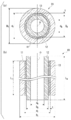
도 1 은, 본 발명의 일 실시형태에 관련된 원통형 스퍼터링 타깃의 개략 설명도이다. (a) 가 축선 (O) 방향에 직교하는 단면도, (b) 가 축선 (O) 을 따른 단면도이다.
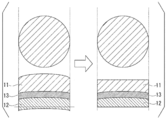
도 2 는, 스퍼터링 타깃재와 접합층의 접합 계면, 및, 백킹 튜브와 접합층의 접합 계면의 확대 설명도이다.
도 3A 는, 스퍼터링 타깃재와 백킹 튜브의 접합 강도를 측정하는 인장 시험편의 채취 방법을 나타내는 설명도이다.
도 3B 는, 스퍼터링 타깃재와 백킹 튜브의 접합 강도를 측정하는 인장 시험편의 채취 방법을 나타내는 설명도이다.
도 4 는, 본 발명의 일 실시형태에 관련된 원통형 스퍼터링 타깃의 제조 방법을 나타내는 플로도이다.
도 5 는, 본 발명의 다른 실시형태에 관련된 원통형 스퍼터링 타깃의 제조 방법을 나타내는 플로도이다.
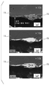
도 6 은, 본 발명예 2 에 있어서의 스퍼터링 타깃재와 접합층의 접합 계면의 관찰 결과를 나타내는 사진이다.
도 7 은, 비교예 1 에 있어서의 스퍼터링 타깃재와 접합층의 접합 계면의 관찰 결과를 나타내는 사진이다.BRIEF DESCRIPTION OF THE DRAWINGS It is a schematic explanatory drawing of the cylindrical sputtering target which concerns on one Embodiment of this invention. (a) is sectional drawing orthogonal to the axis line (O) direction, (b) is sectional drawing along the axis line (O).
2 is an enlarged explanatory view of the bonding interface between the sputtering target material and the bonding layer and the bonding interface between the backing tube and the bonding layer.
It is explanatory drawing which shows the sampling method of the tensile test piece which measures the joint strength of a sputtering target material and a backing tube.
It is explanatory drawing which shows the sampling method of the tensile test piece which measures the joint strength of a sputtering target material and a backing tube.
4 is a flowchart showing a method for producing a cylindrical sputtering target according to an embodiment of the present invention.
5 is a flow diagram showing a method for producing a cylindrical sputtering target according to another embodiment of the present invention.
It is a photograph which shows the observation result of the bonding interface of the sputtering target material and bonding layer in Example 2 of this invention.
7 is a photograph showing a result of observation of a bonding interface between a sputtering target material and a bonding layer in Comparative Example 1. FIG.
이하에, 본 발명의 실시형태인 원통형 스퍼터링 타깃의 제조 방법, 및, 원통형 스퍼터링 타깃에 대해, 첨부된 도면을 참조하여 설명한다.EMBODIMENT OF THE INVENTION Below, the manufacturing method of the cylindrical sputtering target which is embodiment of this invention, and a cylindrical sputtering target are demonstrated with reference to attached drawing.
본 실시형태에 관련된 원통형 스퍼터링 타깃 (10) 은, 도 1 에 나타내는 바와 같이, 축선 (O) 을 따라 연장되는 원통 형상을 이루는 스퍼터링 타깃재 (11) 와, 이 스퍼터링 타깃재 (11) 의 내주측에 삽입된 원통 형상의 백킹 튜브 (12) 를 구비하고 있다.As shown in FIG. 1, the
그리고, 원통 형상의 스퍼터링 타깃재 (11) 와 백킹 튜브 (12) 는, 접합층 (13) 을 개재하여 접합되어 있다.And the cylindrical
스퍼터링 타깃재 (11) 는, 성막하는 박막의 조성에 따른 조성으로 되어, 각종 금속 및 산화물 등으로 구성되어 있으며, 예를 들어 규소 (Si), 티탄 (Ti), 니오브 (Nb) 등으로 구성되어 있다.The
또, 이 원통 형상의 스퍼터링 타깃재 (11) 의 사이즈는, 예를 들어 외경 DT 가 0.15 m ≤ DT ≤ 0.17 m 의 범위 내, 내경 dT 가 0.12 m ≤ dT ≤ 0.14 m 의 범위 내, 축선 (O) 방향 길이 LT 가 0.5 m ≤ LT ≤ 3 m 의 범위 내로 되어 있다.In addition, the size of the cylindrical
백킹 튜브 (12) 는, 원통 형상의 스퍼터링 타깃재 (11) 를 유지하여 기계적 강도를 확보하기 위해 형성된 것이며, 나아가서는 원통 형상의 스퍼터링 타깃재 (11) 에 대한 전력 공급, 및, 원통 형상의 스퍼터링 타깃재 (11) 의 냉각과 같은 기능을 갖는다.The
이 때문에, 백킹 튜브 (12) 로는, 기계적 강도, 전기 전도성 및 열 전도성이 우수할 것이 요구되고 있으며, 예를 들어 SUS304 등의 스테인리스강, 티탄 등으로 구성되어 있다.For this reason, the backing
여기서, 이 백킹 튜브 (12) 의 사이즈는, 예를 들어 외경 DB 가 0.12 m ≤ DB ≤ 0.14 m 의 범위 내, 내경 dB 가 0.11 m ≤ dB ≤ 0.13 m 의 범위 내, 축선 (O) 방향 길이 LB 가 0.5 m ≤ LB ≤ 3 m 의 범위 내로 되어 있다.Here, the size of the
원통 형상의 스퍼터링 타깃재 (11) 와 백킹 튜브 (12) 사이에 개재하는 접합층 (13) 은, 접합재를 사용하여 원통 형상의 스퍼터링 타깃재 (11) 와 백킹 튜브 (12) 를 접합하였을 때에 형성된다.The
접합층 (13) 을 구성하는 접합재는, In 또는 In 합금으로 이루어지는 솔더재로 구성되어 있다. 또한, 접합층 (13) 의 두께 t 는, 0.0005 m ≤ t ≤ 0.004 m 의 범위 내로 되어 있다.The bonding material which comprises the
그리고, 본 실시형태에 관련된 원통형 스퍼터링 타깃 (10) 에 있어서는, 도 2 에 나타내는 바와 같이, 스퍼터링 타깃재 (11) 와 접합층 (13) 의 접합 계면, 및, 백킹 튜브 (12) 와 접합층 (13) 의 접합 계면에 있어서 관찰되는 산화물 (15) 의 최대 두께가 300 ㎚ 이하로 되어 있다.And in the
또한, 본 실시형태에 있어서는, 스퍼터링 타깃재 (11) 와 접합층 (13) 의 접합 계면, 및, 백킹 튜브 (12) 와 접합층 (13) 의 접합 계면에 있어서 관찰되는 두께 150 ㎚ 이상의 산화물 (15) 의 길이 (접합 계면을 따른 길이) 가 1000 ㎚ 이하로 되어 있다.In addition, in this embodiment, the oxide of 150 nm or more observed in the bonding interface of the
또, 본 실시형태인 원통형 스퍼터링 타깃 (10) 에 있어서는, 원통형 스퍼터링 타깃 (10) 의 반경 방향, 즉 적층 방향을 따라 원기둥상으로 잘라낸 인장 시험편을 사용하여, 스퍼터링 타깃재 (11) 와 접합층 (13) 과 백킹 튜브 (12) 를 적층 방향으로 인장 시험하였을 때의 강도가 4 ㎫ 이상으로 되어 있다.In addition, in the
본 실시형태에서는, 도 3A 에 나타내는 바와 같이, 원통형 스퍼터링 타깃 (10) 의 측면으로부터 원기둥상의 샘플을 잘라내었다. 그리고, 도 3B 에 나타내는 바와 같이, 샘플의 단면 (외주면 및 내주면) 을 잘라내어 평탄면으로 함과 함께, 샘플의 외주면을 선반 가공에 의해 절삭하여 측정 시료를 제조하고, 이 측정 시료를 사용하여 인장 강도를 측정한다. 이것을, 스퍼터링 타깃재 (11) 와 접합층 (13), 및, 접합층 (13) 과 백킹 튜브 (12) 의 접합 강도로 한다.In this embodiment, as shown to FIG. 3A, the cylindrical sample was cut out from the side surface of the
이하에, 본 실시형태인 원통형 스퍼터링 타깃 (10) 의 제조 방법에 대해, 도 4 를 사용하여 설명한다.Hereinafter, the manufacturing method of the
(솔더 하지층 형성 공정 S01)(Solder base layer forming step S01)
먼저, 스퍼터링 타깃재 (11) 의 내주면 및 백킹 튜브 (12) 의 외주면에, 용융된 In 또는 In 합금으로 이루어지는 솔더재를 도포하여, 각각 솔더 하지층을 형성한다.First, the solder material which consists of molten In or In alloy is apply | coated to the inner peripheral surface of the
이 솔더 하지층 형성 공정 (솔더재 도포 공정) S01 에 있어서는, 스퍼터링 타깃재 (11) 및 백킹 튜브 (12) 를 가열해 두고, 히터를 탑재한 초음파 인두 등으로 초음파 진동을 가하면서 용융된 In 또는 In 합금으로 이루어지는 솔더재를 도포함으로써, 솔더 하지층을 형성한다. 또한, 이 솔더 하지층 형성 공정 S01 에 있어서의 가열 온도는 170 ℃ 이상 250 ℃ 이하의 범위 내로 되어 있다. 가열 온도는 190 ℃ 이상 230 ℃ 이하의 범위 내가 보다 바람직하다. 여기서, 이 솔더 하지층 형성 공정 S01 에 있어서는, 일본 공개특허공보 2014-037619호에 기재된 방법으로 솔더 하지층을 형성하는 것이 바람직하다.In this solder base layer forming step (solder material applying step) S01, the
(냉각 공정 S02)(Cooling step S02)
다음으로, 솔더 하지층을 형성한 상태에서, 스퍼터링 타깃재 (11) 및 백킹 튜브 (12) 를 조립하기 위해, 일단 실온으로까지 냉각시킨다.Next, in order to assemble the
이 냉각 공정 S02 에 있어서, 스퍼터링 타깃재 (11) 의 내주면 및 백킹 튜브 (12) 의 외주면에 형성된 솔더 하지층의 표면에, In 산화물이 생성된다.In this cooling process S02, In oxide is produced | generated on the surface of the solder base layer formed in the inner peripheral surface of the
(조립 공정 S03)(Assembly process S03)
다음으로, 솔더 하지층을 형성한 스퍼터링 타깃재 (11) 와 백킹 튜브 (12) 를 위치 맞춤하여 조립한다. 이 때, 스페이서 등을 사용하여, 스퍼터링 타깃재 (11) 의 내주면과 백킹 튜브 (12) 의 외주면 사이에 소정의 치수의 간극을 형성해 둔다. 또한, 이 조립 공정 S03 에 있어서는, 일본 공개특허공보 2014-037619호에 기재된 방법으로 스퍼터링 타깃재 (11) 와 백킹 튜브 (12) 를 조립하는 것이 바람직하다.Next, the
(산화물 제거 공정 S04)(Oxide removal step S04)
다음으로, 스퍼터링 타깃재 (11) 의 내주면 및 백킹 튜브 (12) 의 외주면에 형성된 솔더 하지층의 표면에 생성된 산화물을 제거한다.Next, the oxide produced in the surface of the solder base layer formed in the inner peripheral surface of the
본 실시형태에 있어서는, 솔더 하지층을 형성한 스퍼터링 타깃재 (11) 와 백킹 튜브 (12) 를 조립한 상태에서, 환원성 분위기하에서 가열 처리함으로써, 솔더 하지층의 표면에 생성된 산화물을 제거한다.In this embodiment, in the state which assembled the
이 산화물 제거 공정 S04 에 있어서는, 환원성 분위기로서, 예를 들어 수소 가스 분위기, CO 가스 분위기, NH3 분해 가스 분위기, 혹은, 이들의 혼합 가스 분위기 등을 적용할 수 있다. 본 실시형태에서는, 수소 가스 분위기로 한다.In this oxide removal step S04, a reducing atmosphere, for example, can be applied to a hydrogen gas atmosphere, CO gas atmosphere, NH 3 decomposition gas atmosphere, or, a mixed gas atmosphere and the like. In this embodiment, it is set as hydrogen gas atmosphere.
또, 산화물 제거 공정 S04 에 있어서의 가열 조건은, 스퍼터링 타깃재 (11), 백킹 튜브 (12), 및 접합층 (13) 의 재질에 따라 적절히 설정하는 것이 바람직하다. 본 실시형태에서는, 가열 온도가 200 ℃ 이상 350 ℃ 이하의 범위 내로 되어 있고, 이 가열 온도에서의 유지 시간이 60 분 이상 240 분 이하의 범위 내로 되어 있다. 가열 온도는 250 ℃ 이상 300 ℃ 이하의 범위 내로 되는 것이 보다 바람직하고, 유지 시간은 90 분 이상 170 분 이하의 범위 내로 되는 것이 보다 바람직하다.Moreover, it is preferable to set heating conditions in oxide removal process S04 suitably according to the material of the
(솔더 접합 공정 S05)(Solder Bonding Process S05)
다음으로, 산화물 제거 공정 S04 후, 조립한 스퍼터링 타깃재 (11) 의 내주면과 백킹 튜브 (12) 의 외주면의 간극에, 용융된 솔더재를 흘려 넣고, 스퍼터링 타깃재 (11) 와 백킹 튜브 (12) 를 솔더 접합한다.Next, after the oxide removal step S04, a molten solder material is poured into a gap between the inner circumferential surface of the assembled
이 솔더 접합 공정 S05 에 있어서는, 산화물 제거 공정 S04 에 이어서, 환원성 분위기 혹은 N2 가스나 Ar 가스 등의 불활성 가스 분위기에서 실시하는 것이 바람직하다. 또, 이 솔더 접합 공정 S05 에 있어서의 가열 조건은, 접합층 (13) 의 재질에 따라 적절히 설정하는 것이 바람직하다. 본 실시형태에서는, 가열 온도가 170 ℃ 이상 250 ℃ 이하의 범위 내로 되어 있고, 이 가열 온도에서의 유지 시간이 10 분 이상 120 분 이하의 범위 내로 되어 있다. 가열 온도는 190 ℃ 이상 230 ℃ 이하의 범위 내로 되는 것이 보다 바람직하고, 유지 시간은 30 분 이상 90 분 이하의 범위 내로 되는 것이 보다 바람직하다.In this solder bonding process S05, and then the oxide removal step S04, it is preferably performed in an inert gas atmosphere or a reducing atmosphere such as N 2 gas or Ar gas. Moreover, it is preferable to set heating conditions in this solder joint process S05 suitably according to the material of the
또한, 이 솔더 접합 공정 S05 에 있어서는, 일본 공개특허공보 2014-037619호에 기재된 방법으로 스퍼터링 타깃재 (11) 와 백킹 튜브 (12) 의 간극에 솔더재를 흘려 넣는 것이 바람직하다.Moreover, in this solder joint process S05, it is preferable to flow a solder material in the clearance gap between the
이상과 같은 구성으로 된 본 실시형태인 원통형 스퍼터링 타깃 (10) 의 제조 방법에 의하면, 냉각 공정 S02 에 있어서, 솔더 하지층의 표면에 In 산화물이 생성되지만, 냉각 공정 S02 후에, 솔더 하지층의 표면에 생성된 산화물을 제거하는 산화물 제거 공정 S04 를 구비하고 있으므로, 솔더 하지층의 표면에 생성된 산화물이, 스퍼터링 타깃재 (11) 와 접합층 (13) 의 접합 계면, 및, 접합층 (13) 과 백킹 튜브 (12) 의 접합 계면에 응집하는 것을 억제할 수 있어, 스퍼터링 타깃재 (11) 와 접합층 (13) 의 접합 계면, 및, 접합층 (13) 과 백킹 튜브 (12) 의 접합 계면에 형성되는 산화물 (15) 의 두께를 얇게 할 수 있다.According to the manufacturing method of the
따라서, 스퍼터링 타깃재 (11) 와 접합층 (13), 및, 접합층 (13) 과 백킹 튜브 (12) 의 접합 강도가 우수하고, 또한, 방열 특성이 우수한 원통형 스퍼터링 타깃 (10) 을 제조하는 것이 가능해진다.Therefore, the
또, 본 실시형태에 있어서는, 산화물 제거 공정 S04 에서는, 솔더 하지층을 형성한 스퍼터링 타깃재 (11) 및 백킹 튜브 (12) 를, 환원성 분위기하에서 가열 처리함으로써, 솔더 하지층의 표면에 생성된 산화물을 제거하므로, 솔더 하지층의 표면에 생성된 산화물을 환원하여 제거할 수 있다. 또, 솔더 하지층의 내부, 솔더 하지층의 스퍼터링 타깃재 (11) 측의 계면, 솔더 하지층의 백킹 튜브 (12) 측의 계면 등에 존재하는 산화물도 환원 처리에 의해 제거하는 것이 가능해진다.Moreover, in this embodiment, in oxide removal process S04, the oxide produced | generated on the surface of a solder base layer by heat-processing the
또한, 본 실시형태에 있어서는, 산화물 제거 공정 S04 전에, 스퍼터링 타깃재 (11) 와 백킹 튜브 (12) 를 조립하는 조립 공정 S03 을 갖고, 산화물 제거 공정 S04 후에, 계속해서 솔더 접합 공정 S05 를 실시하고 있으므로, 솔더 접합 공정 S05 에 있어서 재가열할 필요가 없어, 효율적으로 원통형 스퍼터링 타깃 (10) 을 제조할 수 있다.In addition, in this embodiment, it has an assembly process S03 which assembles the
본 실시형태인 원통형 스퍼터링 타깃 (10) 에 의하면, 스퍼터링 타깃재 (11) 와 접합층 (13) 의 접합 계면, 및, 백킹 튜브 (12) 와 접합층 (13) 의 접합 계면에 있어서, 산화물 (15) 의 최대 두께가 300 ㎚ 이하로 억제되어 있으므로, 스퍼터링 타깃재 (11) 와 접합층 (13), 및, 백킹 튜브 (12) 와 접합층 (13) 의 접합 강도를 향상시킬 수 있다. 산화물 (15) 의 최대 두께는 250 ㎚ 이하인 것이 보다 바람직하고, 50 ㎚ 이상 220 ㎚ 이하인 것이 더욱 바람직하다.According to the
또, 스퍼터링 타깃재 (11) 와 접합층 (13), 및, 백킹 튜브 (12) 와 접합층 (13) 이 확실하게 접합되어 있으므로, 스퍼터 성막시에 있어서, 스퍼터링 타깃재 (11) 에서 발생한 열을, 백킹 튜브 (12) 측으로 효율적으로 전달할 수 있어, 방열 특성이 우수하다.Moreover, since the
따라서, 스퍼터 성막시에 있어서, 스퍼터링 타깃재 (11) 의 균열이나 접합층 (13) 의 용출의 발생을 억제할 수 있어, 안정적으로 스퍼터 성막을 실시할 수 있다.Therefore, at the time of sputter film formation, generation | occurrence | production of the crack of the
또한, 본 실시형태에 있어서는, 스퍼터링 타깃재 (11) 와 접합층 (13) 의 접합 계면, 및, 백킹 튜브 (12) 와 접합층 (13) 의 접합 계면에 있어서, 두께 150 ㎚ 이상의 산화물 (15) 의 길이가 1000 ㎚ 이하로 억제되어 있으므로, 스퍼터링 타깃재 (11) 와 접합층 (13), 및, 백킹 튜브 (12) 와 접합층 (13) 의 접합 강도를 향상시킬 수 있음과 함께, 방열 특성이 우수하다. 두께 150 ㎚ 이상의 산화물 (15) 의 길이는 710 ㎚ 이하인 것이 보다 바람직하고, 50 ㎚ 이상 460 ㎚ 이하인 것이 더욱 바람직하다.In the present embodiment, the
또, 본 실시형태에 있어서는, 스퍼터링 타깃재 (11) 와 접합층 (13) 과 백킹 튜브 (12) 를 적층 방향으로 인장 시험하였을 때의 강도가 4 ㎫ 이상으로 되어 있으므로, 스퍼터링 타깃재 (11) 와 접합층 (13), 및, 백킹 튜브 (12) 와 접합층 (13) 이 강고하게 접합되어 있어, 방열 특성이 우수하다. 상기 인장 시험하였을 때의 강도는 5 ㎫ 이상인 것이 보다 바람직하고, 6 ㎫ 이상 20 ㎫ 이하인 것이 더욱 바람직하다.Moreover, in this embodiment, since the intensity | strength at the time of the tensile test of the
이상, 본 발명의 실시형태에 대해 설명하였지만, 본 발명은 이것에 한정되지 않고, 그 발명의 기술적 사상을 일탈하지 않는 범위에서 적절히 변경 가능하다.As mentioned above, although embodiment of this invention was described, this invention is not limited to this, It can change suitably in the range which does not deviate from the technical idea of the invention.
본 실시형태에서는, 도 1 에 나타내는 원통형 스퍼터링 타깃을 예로 들어 설명하였지만, 이것에 한정되지 않고, 원통 형상을 이루는 스퍼터링 타깃재와, 이 원통 형상의 스퍼터링 타깃재의 내주측에 접합층을 개재하여 접합된 백킹 튜브를 구비한 원통형 스퍼터링 타깃이면 된다.In this embodiment, although the cylindrical sputtering target shown in FIG. 1 was demonstrated as an example, it is not limited to this, The sputtering target material which forms a cylindrical shape, and it bonded together through the bonding layer on the inner peripheral side of this cylindrical sputtering target material is bonded. What is necessary is just a cylindrical sputtering target provided with a backing tube.
또, 본 실시형태에서는, 도 4 에 나타내는 바와 같이, 조립 공정 S03 후에 산화물 제거 공정 S04 를 실시하는 것으로 하여 설명하였지만, 이것에 한정되지 않고, 도 5 에 나타내는 바와 같이, 냉각 공정 S12 에 이어서 산화물 제거 공정 S13 을 실시하고, 산화물 제거 공정 S13 후에 조립 공정 S14 를 실시해도 된다. 즉, 솔더 하지층을 형성한 스퍼터링 타깃재 (11) 및 백킹 튜브 (12) 를 환원 분위기하에서 가열 처리함으로써, 솔더 하지층의 표면에 생성된 산화물을 제거한 후, 다시 냉각시키고, 조립 공정 S14 에 제공한다. 그리고, 조립 공정 S14 후에 가열 처리하여, 솔더 접합 공정 S15 에서 스퍼터링 타깃재 (11) 와 백킹 튜브 (12) 를 솔더 접합한다. 솔더 접합 공정 S15 에 있어서의 가열 처리의 분위기는, 대기 분위기, 바람직하게는 불활성 가스 분위기, 예를 들어 질소 가스 분위기 또는 아르곤 가스 분위기가 좋다.In addition, in this embodiment, as demonstrated in FIG. 4, it demonstrated as carrying out oxide removal process S04 after granulation process S03. However, it is not limited to this, As shown in FIG. 5, oxide removal follows cooling process S12. Step S13 may be performed and granulation step S14 may be performed after the oxide removal step S13. That is, by heat-processing the
또, 본 실시형태에서는, 산화물 제거 공정을, 환원성 분위기에서 가열 처리함으로써, 솔더 하지층의 표면의 산화물을 환원하여 제거하는 구성으로 하여 설명하였지만, 이것에 한정되지 않는다.In addition, in this embodiment, although the oxide removal process was demonstrated as the structure which reduces and removes the oxide of the surface of a solder base layer by heat-processing in a reducing atmosphere, it is not limited to this.
약액을 사용하여 솔더 하지층의 표면의 산화물을 화학적으로 제거해도 되고, 절삭 가공 등의 기계 가공에 의해 솔더 하지층의 표면의 산화물을 물리적으로 제거해도 된다. 또한, 이러한 구성의 산화물 제거 공정을 실시하는 경우에는, 도 5 에 나타내는 바와 같이, 산화물 제거 공정 S13 후에, 스퍼터링 타깃재와 백킹 튜브를 위치 맞춤하여 조립하는 조립 공정 S14 를 실시하는 것이 바람직하다.An oxide on the surface of the solder underlayer may be chemically removed using a chemical liquid, or an oxide on the surface of the solder underlayer may be physically removed by machining such as cutting. In addition, when performing the oxide removal process of such a structure, as shown in FIG. 5, after oxide removal process S13, it is preferable to perform the granulation process S14 which aligns and assembles a sputtering target material and a backing tube.
실시예Example
이하에, 본 발명에 관련된 원통형 스퍼터링 타깃의 제조 방법, 및, 원통형 스퍼터링 타깃의 작용 효과를 확인하기 위해 실시한 확인 시험의 결과에 대해 설명한다.EMBODIMENT OF THE INVENTION Below, the result of the confirmation method which implemented in order to confirm the effect of the cylindrical sputtering target which concerns on this invention, and the effect of a cylindrical sputtering target is demonstrated.
표 1 에 나타내는 스퍼터링 타깃재, 백킹 튜브, 및, 솔더재를 준비하였다.The sputtering target material, backing tube, and solder material which were shown in Table 1 were prepared.
또한, 스퍼터링 타깃재의 사이즈는, 외경 DT 를 0.162 m, 내경 dT 를 0.135 m, 축선 방향 길이 LT 를 0.60 m 로 하였다.In addition, the size of a sputtering target material is, and the outer diameter D T of 0.162 m, an inner diameter d T of 0.135 m, the axial length L T to 0.60 m.
또, 백킹 튜브의 사이즈는, 외경 DB 를 0.135 m, 내경 dB 를 0.133 m, 축선 방향 길이 LB 를 0.62 m 로 하였다.In addition, the size of the backing tube, and the outer diameter D B of the 0.135 m, 0.133 m internal diameter d B, the axial length L B to 0.62 m.
스퍼터링 타깃재의 내주면 및 백킹 튜브의 외주면에, 초음파 인두를 사용하여 용융된 표 1 에 나타내는 솔더재를 도포하여, 각각 솔더 하지층을 형성하였다. 이 때의 가열 온도는 180 ℃ 로 하였다.The solder material shown in Table 1 melt | dissolved using the ultrasonic iron was applied to the inner peripheral surface of a sputtering target material, and the outer peripheral surface of a backing tube, respectively, and the solder base layer was formed, respectively. The heating temperature at this time was 180 degreeC.
솔더 하지층을 형성한 스퍼터링 타깃재 및 백킹 튜브를 실온까지 냉각시킨 후, 본 발명예에서는, 표 1 에 나타내는 수단에 의해, 솔더 하지층의 표면의 산화물을 제거하는 산화물 제거 공정을 실시하였다. 비교예에서는, 산화물 제거 공정을 실시하지 않았다.After cooling the sputtering target material and backing tube which formed the solder base layer to room temperature, in the example of this invention, the oxide removal process of removing the oxide of the surface of a solder base layer was performed by the means shown in Table 1. In the comparative example, the oxide removal process was not performed.
표 1 의「환원 처리」에 있어서는, H2 분위기하에 있어서 200 ℃ 에서 180 분 유지하는 가열 처리를 실시하고, 산화물을 환원하여 제거하였다.In the "reduction treatment" of Table 1, under a H 2 atmosphere, subjected to a heat treatment for holding at 200 ℃ 180 minutes, which was then removed by reducing the oxide.
표 1 의「약액」에 있어서는, 포름산을 스며들게 한 부직포로 솔더 하지층의 표면을 닦아내고, 그 후, 아세톤으로 세정함으로써, 산화물을 화학적으로 제거하였다.In Table 1, the chemicals were removed chemically by wiping the surface of the solder underlayer with a nonwoven fabric impregnated with formic acid, followed by washing with acetone.
표 1 의「기계 가공」에 있어서는, 솔더 하지층의 표면을 금속제의 스크레이퍼를 사용하여 깎아내어, 산화물을 물리적으로 제거하였다.In "machining" of Table 1, the surface of the solder base layer was scraped off using the metal scraper, and the oxide was physically removed.
그리고, 스퍼터링 타깃재와 백킹 튜브를 위치 맞춤하여 조립하고, 스퍼터링 타깃재와 백킹 튜브의 간극에, 표 1 에 나타내는 솔더재를 흘려 넣고, 일본 공개특허공보 2014-37619에 기재된 방법으로 스퍼터링 타깃재와 백킹 튜브를 솔더 접합하여, 원통형 스퍼터링 타깃을 제조하였다.Then, the sputtering target material and the backing tube are aligned and assembled, and the solder material shown in Table 1 is poured into the gap between the sputtering target material and the backing tube, and the sputtering target material and the sputtering target material by the method described in JP-A-2014-37619. The backing tube was solder bonded to produce a cylindrical sputtering target.
얻어진 원통형 스퍼터링 타깃에 대해, 이하의 항목에 대해 평가하였다.The following items were evaluated about the obtained cylindrical sputtering target.
(산화물)(oxide)
원통형 스퍼터링 타깃의 축선을 통과하는 단면에 있어서, 스퍼터링 타깃재와 접합층의 접합 계면, 및, 접합층과 백킹 튜브의 접합 계면을 관찰하고, EPMA 의 원소 매핑에 의해 산화물을 특정하고, 산화물의 최대 두께, 및, 두께 150 ㎚ 이상의 산화물의 최대 길이를 계측하였다. 평가 결과를 표 1 에 나타낸다. 또, 본 발명예 2 에 있어서의 스퍼터링 타깃재와 접합층의 접합 계면의 관찰 결과를 도 6 에, 비교예 1 에 있어서의 스퍼터링 타깃재와 접합층의 접합 계면의 관찰 결과를 도 7 에 나타낸다.In the cross section passing through the axis of the cylindrical sputtering target, the bonding interface between the sputtering target material and the bonding layer and the bonding interface between the bonding layer and the backing tube are observed, and the oxide is specified by elemental mapping of the EPMA, and the maximum of the oxide is observed. The thickness and the maximum length of the oxide with a thickness of 150 nm or more were measured. The evaluation results are shown in Table 1. Moreover, the observation result of the bonding interface of the sputtering target material and bonding layer in Example 2 of this invention is shown in FIG. 6, and the observation result of the bonding interface of the sputtering target material and bonding layer in Comparative Example 1 is shown in FIG.
(접합 강도)(Bond strength)
도 3A 에 나타내는 바와 같이, 와이어 컷을 사용하여, 얻어진 원통형 스퍼터링 타깃의 측면으로부터 원기둥상의 샘플을 잘라내었다. 이 샘플의 단면 (외주면 및 내주면) 은 도 3B 에 나타내는 바와 같이 잘라내어 평탄면으로 함과 함께, 샘플의 외주면을 기계 가공함으로써 φ 20 ㎜ 의 인장 시험편을 얻었다. 이 인장 시험편을, 인장 시험기 INSTORON5984 (인스트론 재팬사 제조) 에 장착하여 인장 강도를 측정하였다. 또한, 최대 하중 150 kN, 변위 속도를 0.1 ㎜/min 으로 하였다. 측정된 인장 강도를 접합 강도로 하여 표 1 에 나타낸다.As shown to FIG. 3A, the cylindrical sample was cut out from the side surface of the obtained cylindrical sputtering target using the wire cut. The cross section (outer peripheral surface and inner peripheral surface) of this sample was cut out as shown in FIG. 3B, it was made into the flat surface, and the tensile test piece of phi 20 mm was obtained by machining the outer peripheral surface of a sample. This tensile test piece was attached to the tensile tester INSTORON5984 (made by Instron Japan), and the tensile strength was measured. In addition, the maximum load of 150 kN and the displacement speed were set to 0.1 mm / min. Table 1 shows the measured tensile strength as the bonding strength.
(스퍼터 시험)(Sputter test)
표 2 에 나타내는 조건에서 스퍼터 성막을 8 시간 실시하고, 접합층의 용출을 평가하였다.Sputter film formation was performed for 8 hours on the conditions shown in Table 2, and elution of the bonding layer was evaluated.
원통 형상의 스퍼터링 타깃재의 전체 단면에 접하고 있는 접합층의 용출이 없는 것을「A」, 원통 형상의 스퍼터링 타깃재의 전체 단면에 있어서, 축선 방향으로 1 ㎜ 미만의 접합층의 용출이 2 개 지점 이하인 것을「B」, 원통 형상의 스퍼터링 타깃재의 전체 단면에 있어서, 축선 방향으로 1 ㎜ 미만의 접합층의 용출이 3 개 지점 이상 혹은 1 ㎜ 이상의 접합층의 용출이 확인된 것을「C」, 스퍼터링 타깃재의 어긋남이 확인된 것을「D」로 평가하였다. 평가 결과를 표 2 에 나타낸다.No elution of the bonding layer in contact with the entire cross section of the cylindrical sputtering target material, and elution of the bonding layer of less than 1 mm in the axial direction in the entire cross section of the cylindrical sputtering target material, less than two points. "B", in the entire cross section of the cylindrical sputtering target material, the elution of the bonding layer of less than 1 mm in the axial direction of three or more points or the bonding layer of 1 mm or more was confirmed in "C", the sputtering target material What shift was confirmed was evaluated by "D". Table 2 shows the results of the evaluation.


산화물 제거 공정을 실시하지 않은 비교예 1 ∼ 6 에 있어서는, 스퍼터링 타깃재와 접합층의 접합 계면, 및, 접합층과 백킹 튜브의 접합 계면에 있어서의 산화물의 최대 두께가 모두 두껍게 되어 있고, 두께 150 ㎚ 이상의 산화물의 최대 길이도 길어졌다. 또, 도 7 에 나타내는 바와 같이, 비교예 1 에 있어서는, 스퍼터링 타깃재 (11) 와 접합층 (13) 의 접합 계면에 산화물 (15) 이 두껍게 형성되어 있는 것이 확인되었다.In Comparative Examples 1-6 in which the oxide removal process was not performed, the maximum thickness of the oxide in the bonding interface of a sputtering target material and a bonding layer, and the bonding interface of a bonding layer and a backing tube is thick, and is 150 thicknesses. The maximum length of oxides of nm or more also became long. In addition, as shown in FIG. 7, in Comparative Example 1, it was confirmed that the
솔더 접합시에, 솔더 하지층의 표면에 생성된 산화물이, 스퍼터링 타깃재와 접합층의 접합 계면, 및, 접합층과 백킹 튜브의 접합 계면에 응집하여, 산화물이 두껍게 형성된 것으로 추측된다.At the time of solder bonding, the oxide produced on the surface of the solder base layer aggregates at the bonding interface of a sputtering target material and a bonding layer, and the bonding interface of a bonding layer and a backing tube, and it is estimated that thick oxide was formed.
또, 이들 비교예 1 ∼ 6 에 있어서는, 접합 강도가 2 ㎫ 이하로 낮게 되어 있어, 접합 강도가 불충분하였다. 또, 스퍼터 시험 후에 있어서, 접합층의 용출이 발생하였고, 특히 비교예 5 에서는, 스퍼터링 타깃재의 위치 어긋남도 발생하였다. 방열 특성이 불충분하였기 때문인 것으로 추측된다.Moreover, in these comparative examples 1-6, the joining strength was low as 2 Mpa or less, and joining strength was inadequate. Moreover, after the sputtering test, elution of the bonding layer occurred, and in particular, in Comparative Example 5, the positional shift of the sputtering target material also occurred. It is assumed that this is because the heat dissipation characteristic is insufficient.
이에 반해, 솔더 하지층의 표면에 생성된 산화물을 제거한 본 발명예 1 ∼ 18 에 있어서는, 스퍼터링 타깃재와 접합층의 접합 계면, 및, 접합층과 백킹 튜브의 접합 계면에 있어서의 산화물의 최대 두께가 모두 300 ㎚ 이하이고, 두께 150 ㎚ 이상의 산화물의 최대 길이도 1000 ㎚ 이하로 억제되어 있었다. 또, 도 6 에 나타내는 바와 같이, 본 발명예 2 에 있어서는, 스퍼터링 타깃재 (11) 와 접합층 (13) 의 접합 계면에 형성되는 산화물 (15) 이 얇게 되어 있는 것이 확인되었다.In contrast, in Examples 1 to 18 of the present invention in which the oxides formed on the surface of the solder underlayer were removed, the maximum thickness of the oxide at the bonding interface between the sputtering target material and the bonding layer and the bonding interface between the bonding layer and the backing tube. Were all 300 nm or less, and the maximum length of the oxide with a thickness of 150 nm or more was also suppressed to 1000 nm or less. Moreover, as shown in FIG. 6, in Example 2 of this invention, it was confirmed that the
그리고, 이들 본 발명예 1 ∼ 18 에 있어서는, 접합 강도가 모두 4 ㎫ 이상으로 높게 되어 있어, 접합 강도가 높아졌다. 또, 스퍼터 시험 후에 있어서, 접합층의 큰 용출이 없고, 방열 특성이 우수하였다.And in these invention examples 1-18, all the bonding strength became high in 4 Mpa or more, and the bonding strength became high. Moreover, after a sputter test, there was no big elution of a bonding layer, and it was excellent in the heat radiation characteristic.
이상으로부터, 본 발명예에 의하면, 스퍼터링 타깃재와 접합층의 접합 계면, 및, 접합층과 백킹 튜브의 접합 계면에 있어서의 접합 강도, 및, 방열 특성이 우수한 원통형 스퍼터링 타깃을 제조 가능한 원통형 스퍼터링 타깃의 제조 방법, 및, 원통형 스퍼터링 타깃을 제공할 수 있는 것이 확인되었다.As mentioned above, according to the example of this invention, the cylindrical sputtering target which can manufacture the cylindrical sputtering target which is excellent in the bonding interface of a sputtering target material and a bonding layer, and the bonding strength in the bonding interface of a bonding layer and a backing tube, and heat dissipation characteristic. It has been confirmed that the method for producing and the cylindrical sputtering target can be provided.
산업상 이용가능성Industrial availability
본 발명의 제조 방법에 의하면, 스퍼터링 타깃재와 접합층의 접합 계면, 및, 접합층과 백킹 튜브의 접합 계면에 있어서의 접합 강도, 및, 방열 특성이 우수한 원통형 스퍼터링 타깃을 제조할 수 있다.According to the manufacturing method of this invention, the cylindrical sputtering target excellent in the bonding interface of a sputtering target material and a bonding layer, and the bonding interface of a bonding layer and a backing tube, and heat dissipation characteristic can be manufactured.
10 : 원통형 스퍼터링 타깃
11 : 스퍼터링 타깃재
12 : 백킹 튜브
13 : 접합층
15 : 산화물10: Cylindrical Sputtering Target
11: sputtering target material
12: backing tube
13: bonding layer
15: oxide
Claims (7)
상기 스퍼터링 타깃재 및 상기 백킹 튜브를 가열하여, 상기 스퍼터링 타깃재의 내주면 및 상기 백킹 튜브의 외주면에, 용융된 In 또는 In 합금으로 이루어지는 솔더재를 도포하여 솔더 하지층을 형성하는 솔더재 도포 공정과,
상기 솔더재 도포 공정 후에 상기 스퍼터링 타깃재 및 상기 백킹 튜브를 냉각시키는 냉각 공정과,
상기 냉각 공정 후에, 상기 솔더 하지층의 표면에 생성된 산화물을 제거하는 산화물 제거 공정과,
상기 산화물 제거 공정 후에, 상기 스퍼터링 타깃재와 상기 백킹 튜브를, In 또는 In 합금으로 이루어지는 솔더재를 사용하여 솔더 접합하는 솔더 접합 공정을 구비하고 있는 것을 특징으로 하는 원통형 스퍼터링 타깃의 제조 방법.As a manufacturing method of the cylindrical sputtering target provided with the sputtering target material which forms a cylindrical shape, and the backing tube joined to the inner peripheral side of this sputtering target material through the bonding layer which consists of In or In alloy,
A solder material application step of heating the sputtering target material and the backing tube to apply a solder material composed of molten In or In alloy to an inner circumferential surface of the sputtering target material and an outer circumferential surface of the backing tube to form a solder underlayer;
A cooling step of cooling the sputtering target material and the backing tube after the solder material applying step;
An oxide removal step of removing the oxide generated on the surface of the solder underlayer after the cooling step;
And a solder bonding step of solder-bonding the sputtering target material and the backing tube using a solder material made of In or an In alloy after the oxide removal step, wherein the sputtering target material is produced.
상기 산화물 제거 공정에서는, 상기 솔더 하지층을 형성한 상기 스퍼터링 타깃재 및 상기 백킹 튜브를, 환원성 분위기하에서 가열 처리함으로써, 상기 솔더 하지층의 표면에 생성된 산화물을 제거하는 것을 특징으로 하는 원통형 스퍼터링 타깃의 제조 방법.The method of claim 1,
In the said oxide removal process, the sputtering target material and the backing tube which provided the said solder base layer are heat-processed in a reducing atmosphere, and the oxide produced on the surface of the said solder base layer is removed, The cylindrical sputtering target characterized by the above-mentioned. Method of preparation.
상기 산화물 제거 공정에서는, 약액을 사용하여 상기 솔더 하지층의 표면에 생성된 산화물을 제거하는 것을 특징으로 하는 원통형 스퍼터링 타깃의 제조 방법.The method of claim 1,
In the oxide removal step, a method of producing a cylindrical sputtering target, characterized in that the oxide produced on the surface of the solder underlayer is removed using a chemical solution.
상기 산화물 제거 공정에서는, 기계 가공에 의해 상기 솔더 하지층의 표면에 생성된 산화물을 제거하는 것을 특징으로 하는 원통형 스퍼터링 타깃의 제조 방법.The method of claim 1,
In the said oxide removal process, the oxide produced | generated on the surface of the said solder base layer is removed by machining, The manufacturing method of the cylindrical sputtering target characterized by the above-mentioned.
상기 스퍼터링 타깃재와 상기 접합층의 접합 계면, 및, 상기 백킹 튜브와 상기 접합층의 접합 계면에 있어서, 산화물의 최대 두께가 300 ㎚ 이하로 되어 있는 것을 특징으로 하는 원통형 스퍼터링 타깃.As a cylindrical sputtering target provided with the sputtering target material which forms a cylindrical shape, and the backing tube joined to the inner peripheral side of this sputtering target material through the bonding layer which consists of In or In alloy,
A cylindrical sputtering target, wherein the maximum thickness of the oxide is 300 nm or less in the bonding interface between the sputtering target material and the bonding layer and the bonding interface between the backing tube and the bonding layer.
상기 스퍼터링 타깃재와 상기 접합층의 접합 계면, 및, 상기 백킹 튜브와 상기 접합층의 접합 계면에 있어서, 두께 150 ㎚ 이상의 산화물의 길이가 1000 ㎚ 이하로 되어 있는 것을 특징으로 하는 원통형 스퍼터링 타깃.The method of claim 5,
A cylindrical sputtering target, wherein the length of the oxide having a thickness of 150 nm or more is 1000 nm or less in the bonding interface between the sputtering target material and the bonding layer and the bonding interface between the backing tube and the bonding layer.
상기 스퍼터링 타깃재와 상기 접합층과 상기 백킹 튜브를 적층 방향으로 인장 시험하였을 때의 강도가 4 ㎫ 이상인 것을 특징으로 하는 원통형 스퍼터링 타깃.The method according to claim 5 or 6,
A cylindrical sputtering target, wherein the sputtering target material, the bonding layer, and the backing tube have a strength of 4 MPa or more when subjected to a tensile test in a stacking direction.
Applications Claiming Priority (3)
| Application Number | Priority Date | Filing Date | Title |
|---|---|---|---|
| JPJP-P-2017-066107 | 2017-03-29 | ||
| JP2017066107A JP2018168417A (en) | 2017-03-29 | 2017-03-29 | Method for manufacturing cylindrical sputtering target and cylindrical sputtering target |
| PCT/JP2018/010225 WO2018180545A1 (en) | 2017-03-29 | 2018-03-15 | Cylindrical sputtering target production method and cylindrical sputtering target |
Publications (1)
| Publication Number | Publication Date |
|---|---|
| KR20190131029A true KR20190131029A (en) | 2019-11-25 |
Family
ID=63675783
Family Applications (1)
| Application Number | Title | Priority Date | Filing Date |
|---|---|---|---|
| KR1020197027149A KR20190131029A (en) | 2017-03-29 | 2018-03-15 | Manufacturing method of cylindrical sputtering target, and cylindrical sputtering target |
Country Status (6)
| Country | Link |
|---|---|
| EP (1) | EP3604610A4 (en) |
| JP (1) | JP2018168417A (en) |
| KR (1) | KR20190131029A (en) |
| CN (1) | CN110402300A (en) |
| TW (1) | TWI751304B (en) |
| WO (1) | WO2018180545A1 (en) |
Families Citing this family (3)
| Publication number | Priority date | Publication date | Assignee | Title |
|---|---|---|---|---|
| JP7172580B2 (en) * | 2018-12-26 | 2022-11-16 | 三菱マテリアル株式会社 | Manufacturing method of cylindrical sputtering target |
| JP7120111B2 (en) * | 2019-03-25 | 2022-08-17 | 三菱マテリアル株式会社 | Manufacturing method of cylindrical sputtering target |
| CN111304605A (en) * | 2020-03-09 | 2020-06-19 | 东莞市欧莱溅射靶材有限公司 | ITO (indium tin oxide) rotary target binding method |
Citations (1)
| Publication number | Priority date | Publication date | Assignee | Title |
|---|---|---|---|---|
| JP2014037619A (en) | 2012-07-18 | 2014-02-27 | Mitsubishi Materials Corp | Cylindrical sputtering target and method of manufacturing the same |
Family Cites Families (11)
| Publication number | Priority date | Publication date | Assignee | Title |
|---|---|---|---|---|
| JPH01179767A (en) * | 1988-01-06 | 1989-07-17 | Hitachi Ltd | Method for soldering ceramics |
| JP2622716B2 (en) * | 1988-05-14 | 1997-06-18 | 株式会社ジャパンエナジー | Immersion bonding method and apparatus |
| JPH06128735A (en) * | 1992-10-20 | 1994-05-10 | Mitsubishi Kasei Corp | Production of sputtering target |
| JPH1046327A (en) * | 1996-07-31 | 1998-02-17 | Sumitomo Chem Co Ltd | Sputtering target and its production |
| JP3404021B2 (en) * | 2001-01-18 | 2003-05-06 | 富士通株式会社 | Soldering equipment |
| TW570856B (en) * | 2001-01-18 | 2004-01-11 | Fujitsu Ltd | Solder jointing system, solder jointing method, semiconductor device manufacturing method, and semiconductor device manufacturing system |
| TWI274622B (en) * | 2003-04-28 | 2007-03-01 | Air Prod & Chem | Apparatus and method for removal of surface oxides via fluxless technique involving electron attachment and remote ion generation |
| US7079370B2 (en) * | 2003-04-28 | 2006-07-18 | Air Products And Chemicals, Inc. | Apparatus and method for removal of surface oxides via fluxless technique electron attachment and remote ion generation |
| KR101341705B1 (en) * | 2010-11-24 | 2013-12-16 | 플란제 에스이 | Method for bonding rotary target for sputtering |
| JP2017066107A (en) | 2015-09-30 | 2017-04-06 | 株式会社東洋新薬 | Skin external composition and ultraviolet-protecting cosmetic |
| JP6376101B2 (en) * | 2015-10-27 | 2018-08-22 | 住友金属鉱山株式会社 | Cylindrical sputtering target and manufacturing method thereof |
-
2017
- 2017-03-29 JP JP2017066107A patent/JP2018168417A/en active Pending
-
2018
- 2018-03-15 CN CN201880017587.3A patent/CN110402300A/en active Pending
- 2018-03-15 EP EP18774832.2A patent/EP3604610A4/en not_active Withdrawn
- 2018-03-15 WO PCT/JP2018/010225 patent/WO2018180545A1/en unknown
- 2018-03-15 KR KR1020197027149A patent/KR20190131029A/en not_active Application Discontinuation
- 2018-03-21 TW TW107109556A patent/TWI751304B/en active
Patent Citations (1)
| Publication number | Priority date | Publication date | Assignee | Title |
|---|---|---|---|---|
| JP2014037619A (en) | 2012-07-18 | 2014-02-27 | Mitsubishi Materials Corp | Cylindrical sputtering target and method of manufacturing the same |
Also Published As
| Publication number | Publication date |
|---|---|
| EP3604610A1 (en) | 2020-02-05 |
| WO2018180545A1 (en) | 2018-10-04 |
| TW201839156A (en) | 2018-11-01 |
| CN110402300A (en) | 2019-11-01 |
| EP3604610A4 (en) | 2021-01-20 |
| JP2018168417A (en) | 2018-11-01 |
| TWI751304B (en) | 2022-01-01 |
Similar Documents
| Publication | Publication Date | Title |
|---|---|---|
| KR102459745B1 (en) | Copper/ceramic bonded body, insulated circuit board, and copper/ceramic bonded body manufacturing method, insulated circuit board manufacturing method | |
| KR20190131029A (en) | Manufacturing method of cylindrical sputtering target, and cylindrical sputtering target | |
| CN104711457B (en) | High temperature solder and application thereof | |
| JPWO2006016479A1 (en) | Heat sink member and manufacturing method thereof | |
| WO2016152648A1 (en) | Copper alloy sheet for heat dissipating component and heat dissipating component | |
| TWI331550B (en) | A diffusion bonding method for blocks of based bulk metallic glass | |
| JP2008194750A (en) | Method for preventing embrittlement and enhancing bonding force of interface between titanium using silver diffusion-controlled layer and dissimilar metal | |
| JP2016180174A (en) | Copper alloy sheet for heat radiation component | |
| CN108947558A (en) | A kind of metal and Ti3SiC2The connection method of ceramics | |
| KR100701193B1 (en) | Fabrication Method of AuSn ductile soldering strips | |
| KR101039361B1 (en) | Low temperature joining method between Ti/Ti-based alloys having a bonding strength higher than those of base metals | |
| JP6928297B2 (en) | Copper / ceramic joints and insulated circuit boards | |
| WO2021117327A1 (en) | Copper/ceramic assembly and insulated circuit board | |
| WO2019176677A1 (en) | Cylindrical sputtering target, sputtering target material, and method for manufacturing cylindrical sputtering target | |
| KR20110130930A (en) | Method for diffusion bonding of nickel-based alloys | |
| KR20210039329A (en) | Cylindrical sputtering target, In-based solder material, and manufacturing method of cylindrical sputtering target | |
| JP5286507B2 (en) | Method for producing Cr-Cu alloy plate | |
| JP2004232069A (en) | Copper-based alloy, and material for heat radiating plate obtained by using the copper-based alloy | |
| CN113385851B (en) | High-temperature-resistant corrosion-resistant solder for silicon carbide ceramic connection and preparation method and application thereof | |
| KR102357819B1 (en) | Cylindrical Sputtering Target | |
| CN109465570B (en) | Ti-Si high-temperature brazing filler metal | |
| JP2016098165A (en) | Soldering method for jointing solder to ceramic | |
| Koleňák et al. | Joining active metals with Al2O3 by use of solders | |
| JP2019163539A (en) | Cylindrical sputtering target, sputtering target material, and method of manufacturing cylindrical sputtering target | |
| JP6419657B2 (en) | Material for lid of electronic component package and manufacturing method thereof |
Legal Events
| Date | Code | Title | Description |
|---|---|---|---|
| A201 | Request for examination | ||
| E902 | Notification of reason for refusal | ||
| E601 | Decision to refuse application |